Embed Size (px)
Citation preview
Overhauling the
Jonathan Jones
takes time to
dismantle the
ubiquitous Smiths
speedometer, and
finds out what makes
it tick.
ACTION PHOTOGRAPHY : ANGIEJONES
H
ow fast does it go mister? Smallboys are apt to believe the 120mphmarking on a speedometer, even
when it's fitted to a 600cc plodder . But alltoo often, when the motor cycle getsmoving, the speedometer needle doesn't.And one peep inside the Smiths Chrono-metric can be enough to keep ridersguessing their legality in 30 mph limits,and ignoring indicated speeds of 75between the front gate and the garage.
Dismantling the Chronometric isn't thatdaunting . It can be a nice little kitchentable job for a chilly evening, and once youget a grip on the principle, fault findingisn't difficult . The worst that can happen is
that you'll forget where the bits went, butwith our photographs and step-by-stepguide, you should be able to geteverything back in the right order.The Chronometric speedometer is
common to hundreds of machines of thepost-war period ; you'll find exactly thesame movement in the little D shapedinstrument, used by dozens of light-weights. If a trip reset extension is fitted,remove it to make the assembly less un-wieldy, and address problem number 1;getting inside.
The D style is simple, just undo thethree screws around the base, but thechrome bezels on the circular type can put
Mileometer drumremoved to show thestandardChronometricspeedometermechanism . Pullingthe trip reset spindle(left) releases theratchet,simultaneouslyengaging the cog toallow the meterdrums to be zeroed .
The heart of the Chronometricmovement is its escapement,which sets the camshaft speedand ensures accuracy.
6 Motorgycle APRIL 1992
Chronometric
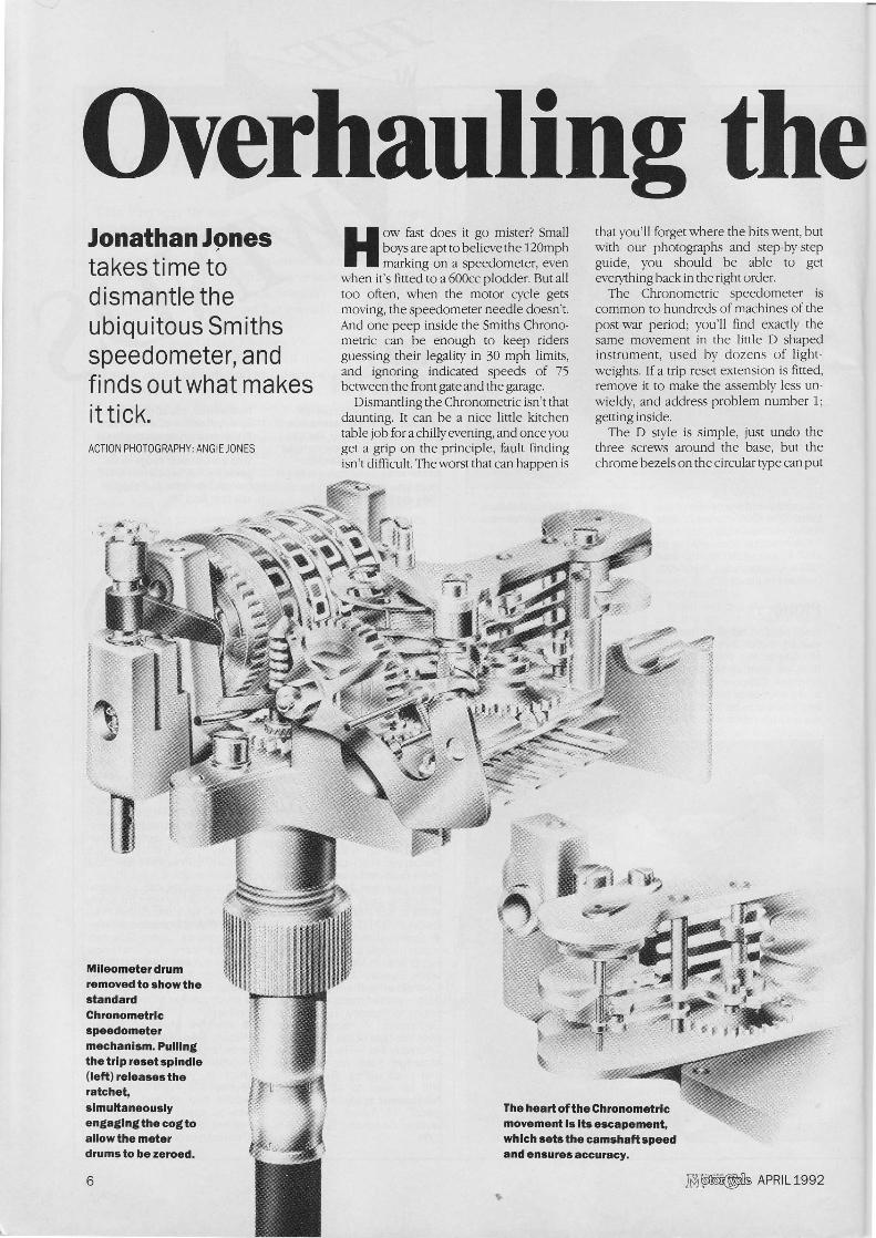
Needle is a pressfit on its shaft ; usegentle leverage beneath the face, toremove it.
Removal of top plate reveals thecomplete mechanism . Support In a viceto make dismantling easier .
the brake on things . Warmth workswonders — a rag soaked in hot water willusually free the fine threads — and with acloth wrapped around the top, it can oftenbe undone by hand . Like you, I've comeacross bezels which have been notched toprovide a purchase point, but it's far betterto apply force evenly . If hand pressuredoesn't do the trick, try an oil-filter strapwrench — the nylon webbing type —applied carefully to the ring . Gentle heatand perseverance is the key . Take off thesealing rubber, glass and supporting ring.It makes putting it back together easier ifyou use a separate container for eachassembly plastic margarine tubs areideal .
Turn the case over, and remove thescrews and starlock washers which holdthe gubbins inside, supporting it by thecable attachment to stop it falling flat on itsface. (The D type screws down frominside.) Take out the mechanism andundo the dial screws . Operators blessedwith only two hands may like to supportthe assembly in a small vice.
Now, using two screwdrivers under theface to prevent damage to the surface,carefully lever off the press fitted needle . Ifyou choose the right size, they can beoperated with a cam action, twisting theshafts until the needle pops off. Removethe top plate, where fitted, and before yougo any further, inspect the works for signsof distress.
Much of the mechanism is brass, socorrosion is not usually a problem, thoughover-lubrication can be . Metal dust is morecommon, and the most likely cause isupward thrust on the drive shaft, caused byinner cables which are over long . If you'relucky it won't be too late, but do look outfor a half-dead instrument at autojumbles;it can make a useful parts store.
Two screws in the base remove theChronometric movement — similar for allinstruments which can be laid asidewhilst the odometer section is serviced.
An eccentric wheel is at the centre of theratchet mechanism which operates themileage recorder, and the trip meterwhere fitted . Undo the outer locknut, andunscrew the 7BA bolt from the inside . Theorder, which can be seen in the photo-graph, is bolt; brass shim ; pawl to tripmeter, with spring ; eccentric wheel andspacing washer ; odometer pawl and
spring ; driving gear and pin ; brassshim ; supporting pillar on base;
outer plate with pin which takes thetwo pawl springs ; and finally the locknut.
Now the way is clear to remove andinspect the drive shaft, with its pinion andworm. Take out the screw, slide the platefrom its slot and lift out the shaft, whichsits on a brass washer on top of a feltlubricating pad.
Take the greatest care with cleaning,since even mild solvents will remove dialand odometer drum figures with remark-able efficiency . I have never found itnecessary to dismantle the drums, prefer-ring to use soapy water and cotton wool—cotton buds, as sold by chemists, areideal . Mileage can be zeroed by springingthe retainers gently back; useful if you areputting together an instrument for a`rebuilt as new' machine.
Two screws attach the Chronometricmovement to the main casting. Oil-retaining pads let into the base keep thespindles well lubricated for thousandsof miles.
APRIL 1992 Motor gele
7
Overhauling the
Chronometric
Wash the Chronometric movement byswilling it in petrol — white spirit is moreacceptable inside the house — using asmall brush to dislodge the muck. Over-oiling of cables ; or tachometer driveswhich pump engine oil'upwards, are themain culprits here . Brass gears are self-lubricating and don't need lashings of axlegrease. Dry carefully and prepare for thereally interesting bit.
I have an aversion to instructions whichsay blithely : RE-ASSEMBLY IS THEREVERSE OF DISMANTLING. Everyoneknows that taking things to bits is the easypart, and that all the problems start whenbolting it back together . So lets assume
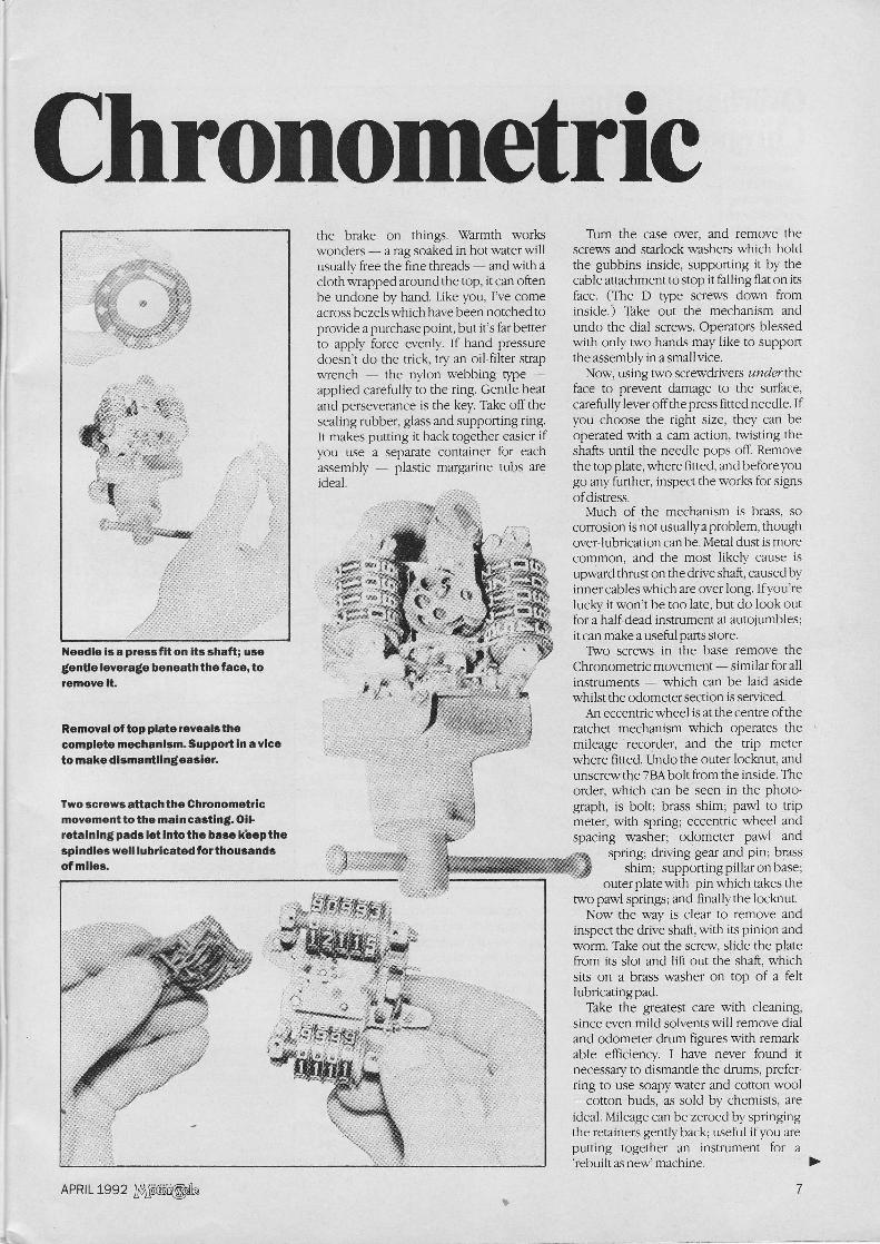
Screw and plate retain the main drive spindle . Note the particlesof metal around this one ; an outward sign of mechanical malaise.
Worm on driveshaft turns gearA,and eccentricdrive to the pawlB,which turnsthe recordingdrum ratchet.
that each piece is scrupulously clean, andtry a different approach, describing how toassemble the mechanism, and advisingthat: DISMANTLING IS THE REVERSE OFRE-ASSEMBLY.
Begin with the camshaft and its brassescape wheel, which is regulated by theescapement anchor and driven through aclutch. Take the shaft, fit the small plasticdisc ; the diabolo spring ; the large plasticdisc ; the pinion with its recess outward.Compressing the spring gently, slip thefibre retaining clip into its groove . Placethe camshaft in the centre hole of base plate.
Next the needle assembly, which fits thecaptive shaft on the base plate . Fit awasher, followed by the fibre gear, boss to
Petrol and a smallbrush will take thegrease from amucky movementbeforedismantling, butkeep all solventsaway from theface andmileometerdrums.
the top, and — meshing with it — thedriving pinion and its rocking mainshaft.Then, onto the captive shaft place anotherwasher; the integrator wheel assemblywith its three-spring clutch, pinion to thetop, and the hairspring fitting in its groovein the post.
Fit the next washer, followed by therecorder wheel, again hooking the springaround the post . Slip on the rockingspindle's top bearing, which is one end ofthe rocker which pivots on the post, whileits forked end locates either side of the topcam. A final washer on the main shaft isfollowed by the stabiliser wheel, its stub tothe top and the small hole accepting therecorder wheel's pin .
How it works
The speedometercable turns a chainof gears which drive a camshaft, itsspeed set by the escapement and itsbalance wheel.
One cam operates a rocker, whichpulls a rocking spindle into mesh withthe integrator wheel, turning this asfar as it will go —dependent uponinput speed — in 3/4 of a second . Theintegrator wheel drives the recorderwheel, and a pin locates with thestabiliser wheel, which carries theneedle.
After 3/4 of a second, the camshaftdisengages the rocking spindle, butthe wheel is held by a sprung fingerengaging in its teeth . The integratorwheel is released, and a hair springreturns it to zero . Soon afterwards thecam releases a third spring on therecorder wheel, which returns to zerowith the needle.
In practice, the rocking spindle willre-engage before the needle returnsto zero, unless the drive has stopped.So the recorder wheel will react to anychange in the number of revolutions itmakes in 3/4 of a second, transferringthis to the needle.
8
Motor gcle APRIL 1992
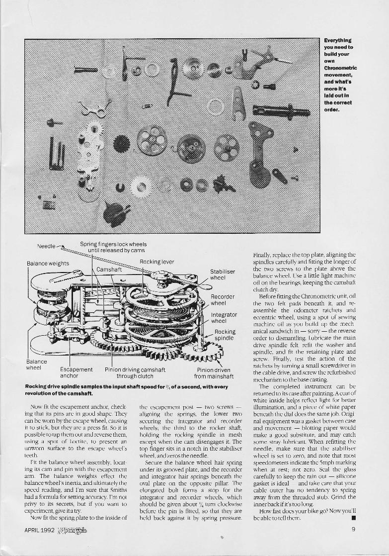
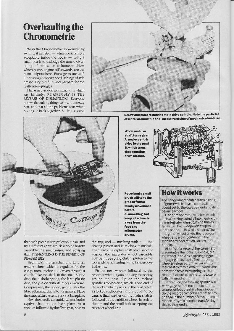
Everythingyou need tobuild yourownChronometricmovement,and what'smore it'slaid out inthe correctorder.
Escapement
Pinion driving camshaftanchor
through clutch
Spring fingers lockwheelsuntil released by cams
Rocking leverCamshaft
-
Rocking drive spindle samples the input shaft speed for 3/4 of a second, with everyrevolution of the camshaft
Now fit the escapement anchor, check-ing that its pins are in good shape . Theycan be worn by the escape wheel, causingit to stick, but they are a press fit. So it ispossible to tap them out and reverse them,using a spot of Loctite, to present anunworn surface to the escape wheel'steeth.
Fit the balance wheel assembly, locat-ing its cam and pin with the escapementarm. The balance weights effect thebalance wheel's inertia, and ultimately thespeed reading, and I'm sure that Smithshad a formula for setting accuracy . I'm notprivy to its secrets, but if you want toexperiment, give it a try.
Now fit the spring plate to the inside of
the escapement post — two screws —aligning the springs, the lower twosecuring the integrator and recorderwheels ; the third to the rocker shaft,holding the rocking spindle in meshexcept when the cam disengages it . Thetop finger sits in a notch in the stabiliserwheel, and zeros the needle.
Secure the balance wheel hair springunder its grooved plate, and the recorderand integrator hair springs beneath theoval plate on the opposite pillar . Theelongated bolt forms a stop for theintegrator and recorder wheels, whichshould be given about turn clockwisebefore the pin is fitted, so that they areheld back against it by spring pressure .
Finally, replace the top plate, aligning thespindles carefully and fitting the longer ofthe two screws to the plate above thebalance wheel. Use a little light machineoil on the bearings, keeping the camshaftclutch dry.
Before fitting the Chronometric unit, oilthe two felt pads beneath it, and re-assemble the odometer ratchets andeccentric wheel, using a spot of sewingmachine oil as you build up the mech-anical sandwich in — sorry the reverseorder to dismantling . Lubricate the maindrive spindle felt, refit the washer andspindle, and fit the retaining plate andscrew. Finally, test the action of theratchets by turning a small screwdriver inthe cable drive, and screw the refurbishedmechanism to the base casting.The completed instrument can be
returned to its case after painting . A coat ofwhite inside helps reflect light for betterillumination, and a piece of white paperbeneath the dial does the same job . Origi-nal equipment was a gasket between caseand movement — blotting paper wouldmake a good substitute, and may catchsome stray lubricant. When refitting theneedle, make sure that the stabiliserwheel is set to zero, and note that mostspeedometers indicate the 5mph markingwhen at rest ; not zero. Seal the glasscarefully to keep the rain out siliconegasket is ideal — and take care that yourcable outer has no tendency to springaway from the threaded stub . Grind theinner back if it's too long.
How fast does your bike go? Now you'llbe able to tell them .
n
Balance weights
Balancewheel Pinion driven
from mainshaft
APRIL 1992 Motor cycle
9