Embed Size (px)
Citation preview
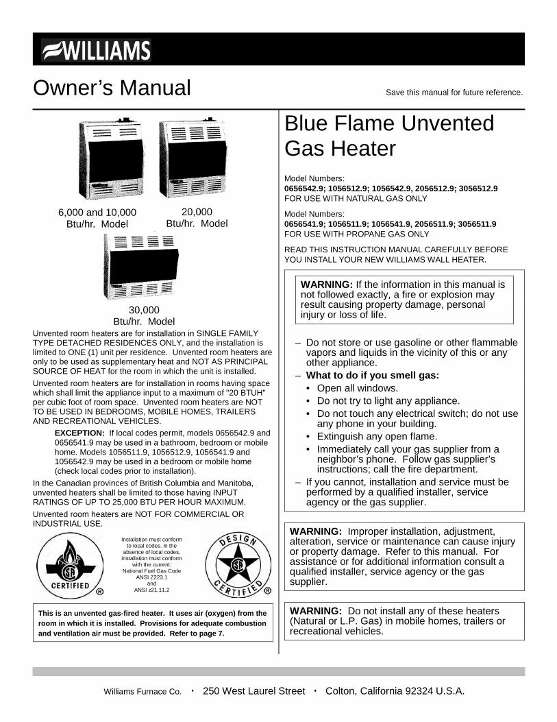
Owner’s Manual Save this manual for future reference.
1
Unvented room heaters are for installation in SINGLE FAMILY TYPE DETACHED RESIDENCES ONLY, and the installation is limited to ONE (1) unit per residence. Unvented room heaters are only to be used as supplementary heat and NOT AS PRINCIPAL SOURCE OF HEAT for the room in which the unit is installed. Unvented room heaters are for installation in rooms having space which shall limit the appliance input to a maximum of "20 BTUH" per cubic foot of room space. Unvented room heaters are NOT TO BE USED IN BEDROOMS, MOBILE HOMES, TRAILERS AND RECREATIONAL VEHICLES.
EXCEPTION: If local codes permit, models 0656542.9 and 0656541.9 may be used in a bathroom, bedroom or mobile home. Models 1056511.9, 1056512.9, 1056541.9 and 1056542.9 may be used in a bedroom or mobile home (check local codes prior to installation).
In the Canadian provinces of British Columbia and Manitoba, unvented heaters shall be limited to those having INPUT RATINGS OF UP TO 25,000 BTU PER HOUR MAXIMUM. Unvented room heaters are NOT FOR COMMERCIAL OR INDUSTRIAL USE.
This is an unvented gas-fired heater. It uses air (oxygen) from the room in which it is installed. Provisions for adequate combustion and ventilation air must be provided. Refer to page 7.
Blue Flame Unvented Gas Heater Model Numbers: 0656542.9; 1056512.9; 1056542.9, 2056512.9; 3056512.9 FOR USE WITH NATURAL GAS ONLY
Model Numbers: 0656541.9; 1056511.9; 1056541.9, 2056511.9; 3056511.9 FOR USE WITH PROPANE GAS ONLY
READ THIS INSTRUCTION MANUAL CAREFULLY BEFORE YOU INSTALL YOUR NEW WILLIAMS WALL HEATER.
– Do not store or use gasoline or other flammable vapors and liquids in the vicinity of this or any other appliance.
– What to do if you smell gas: • Open all windows. • Do not try to light any appliance. • Do not touch any electrical switch; do not use
any phone in your building. • Extinguish any open flame. • Immediately call your gas supplier from a
neighbor’s phone. Follow gas supplier’s instructions; call the fire department.
– If you cannot, installation and service must be performed by a qualified installer, service agency or the gas supplier.
WARNING: Improper installation, adjustment, alteration, service or maintenance can cause injury or property damage. Refer to this manual. For assistance or for additional information consult a qualified installer, service agency or the gas supplier.
WARNING: Do not install any of these heaters (Natural or L.P. Gas) in mobile homes, trailers or recreational vehicles.
30,000 Btu/hr. Model
WARNING: If the information in this manual is not followed exactly, a fire or explosion may result causing property damage, personal injury or loss of life.
6,000 and 10,000 Btu/hr. Model
Williams Furnace Co. 250 West Laurel Street Colton, California 92324 U.S.A.
20,000 Btu/hr. Model
Installation must conform to local codes. ln the
absence of local codes, installation must conform
with the current: National Fuel Gas Code
ANSI Z223.1 and
ANSI z21.11.2
Warranty
2
Warranty & Installation Record – 2
The Manufacturer, Williams Furnace Co., warrants this wall heater or heater to the original purchaser under the following conditions: LIMITED ONE-YEAR WARRANTY 1. Any part thereof which proves to be defective in material or workmanship within one year from date of original purchase for use will be repaired or replaced
at the Manufacturer’s option, FOB, its factory. 2. No liability is assumed by the Manufacturer for removal or installation labor costs, nor for freight or delivery charges. LIMITED EXTENDED WARRANTY 1. In addition to the above limited one-year warranty on the complete unit, any combustion chamber which burns out or rusts under normal installation, use and service
conditions during a period of nine years following expiration of the one-year warranty period will be exchanged for a like or functionally similar part. 2. No liability is assumed by the Manufacturer for removal or installation labor costs, nor for freight or delivery charges. LIMITATIONS 1. THIS LIMITED WARRANTY IS THE ONLY WARRANTY MADE BY THE MANUFACTURER, IMPLIED WARRANTIES OF MERCHANTABILITY OR FITNESS FOR ANY
PARTICULAR PURPOSE ARE LIMITED TO THE SAME ONE YEAR TERM AS THE EXPRESS WARRANTY. UNDER NO CIRCUMSTANCES SHALL THE MANUFACTURER BE LIABLE FOR INCIDENTAL, CONSEQUENTIAL, SPECIAL OR CONTINGENT DAMAGES OR EXPENSES ARISING DIRECTLY OR INDIRECTLY FROM ANY DEFECT IN THE PRODUCT OR ANY COMPONENT OR FROM THE USE THEREOF THE REMEDIES SET FORTH HEREIN ARE THE EXCLUSIVE REMEDIES AVAILABLE TO THE USER AND ARE IN LIEU OF ALL OTHER REMEDIES.
Some states do not allow limitation on how long an implied warranty lasts, and some states do not allow the exclusion or limitation of incidental or consequential damages, so the above limitations or exclusions may not apply to you.
2. This warranty does not include any charge for labor or installation. 3. This warranty does not extend to painted surfaces nor to damage or defects resulting from accident, alteration, misuses or abuse or improper installation. 4. This warranty does not cover claims which do not involve defective workmanship or materials. DUTIES OF THE CONSUMER 1. The heating equipment must be installed by a qualified installer and operated in accordance with the installation and homeowner’s instructions furnished with the
equipment. 2. Any travel, diagnostic costs, service labor, and labor to repair the defective unit will be the responsibility of the owner. 3. A bill of sale, cancelled check, payment record or permit should be kept to verify purchase date to establish the warranty period. 4. Have the installer enter the requested information in the space below. GENERAL 1. The Manufacturer neither assumes nor authorizes any person to assume for it any other obligation or liability in connection with said equipment. 2. Service under this warranty should be obtained by contacting your dealer. Provide the dealer with the model number, serial number, and purchase date verification. 3. If, within a reasonable time after contacting your dealer, satisfactory service has not been received, contact: Customer Service Department, 250 West Laurel Street,
Colton, CA 92324 for assistance. 4. THIS WARRANTY GIVES YOU SPECIFIC LEGAL RIGHTS AND YOU MAY ALSO HAVE OTHER RIGHTS WHICH VARY FROM STATE TO STATE.
Installation Record Original Purchaser ____________________________________________________________________________________________
Model No. ______________________________________________________________ Serial No. ___________________________
Address ____________________________________________________________________________________________________
City and State ___________________________________________________________ Zip ________________________________
Dealer _____________________________________________________________________________________________________
Address ____________________________________________________________________________________________________
City and State ___________________________________________________________ Zip ________________________________
Installation date _______________ Signed by ______________________________________________________________________
(Dealer or authorized representative who certifies that this appliance in accordance with manufacturer’s instructions and local codes.)
Contents
3
Your Williams Warranty ................................................................. 2 Installation Record ......................................................................... 2 Table of Contents .......................................................................... 3 Safety Rules .................................................................................. 4 Introduction ................................................................................ 5-6 Provisions for Adequate Combustion and Ventilation Air .............. 7 Installing Your Heater .............................................................. 8-12 Operating Your Heater .......................................................... 12-13 Caring for Your Heater ................................................................ 14 Troubleshooting Your Heater ................................................ 15-16 Order Replacement Parts ...................................................... 16-23 Installing and Operating Your Blower Accessory ......................... 24 Installing Your Floor Base Accessory …. .................................... 25 Additional References ........................................................... 26-27 Service Hints ............................................................................... 28
Safety Rules
4
WARNING: Read these rules and the instructions carefully. Failure to follow these rules and instructions could cause a malfunction of the heater. This could result in death, serious bodily injury and/or property damage.
INSTALLATION MUST CONFORM TO LOCAL CODES. IN THE ABSENCE OF LOCAL CODES, INSTALLATION MUST CONFORM TO THE NATIONAL FUEL GAS CODE, ANSI Z223.1.
INSTALLATION AND REPAIR SHOULD BE DONE BY A QUALIFIED SERVICE TECHNICIAN. THE APPLIANCE SHOULD BE INSPECTED BEFORE USE AND AT LEAST ANNUALLY BY A PROFESSIONAL SERVICE TECHNICIAN. MORE FREQUENT CLEANING MAY BE REQUIRED DUE TO EXCESSIVE LINT FROM SOME CARPETING, BEDDING MATERIAL, ETC. IT IS IMPERATIVE THAT CONTROL COMPARTMENTS, BURNERS AND CIRCULATING AIR PASSAGEWAYS OF THE APPLIANCE BE KEPT CLEAN.
SEE CARBON MONOXIDE WARNING ON PAGE 12. YOUNG CHILDREN SHOULD BE CAREFULLY SUPERVISED WHEN THEY ARE IN THE SAME ROOM WITH THE APPLIANCE. ANY SAFETY SCREEN, GUARD OR PARTS REMOVED FOR SERVICING AN APPLIANCE MUST BE REPLACED PRIOR TO OPERATING THE APPLIANCE TO AVOID PROPERTY DAMAGE, BODILY INJURY OR DEATH. CHILDREN AND ADULTS SHOULD BE ALERTED TO THE HAZARD OF HIGH SURFACE TEMPERATURE AND SHOULD STAY AWAY TO AVOID BURNS OR CLOTHING IGNITION. DUE TO HIGH TEMPERATURES, THE APPLIANCE SHOULD BE LOCATED OUT OF TRAFFIC AND AWAY FROM FURNITURE AND DRAPERIES.
WARNING: Any change to this heater or its controls could cause injury or death.
1. Use only manufacturer’s replacement parts. Use of any other
parts could cause injury or death.
2. Be sure the heater is for type of gas to be used. Do not change it to use with other gases. Unsafe operation could result and could cause bodily injury and death.
3. It is prohibited to install the heater in a bedroom, trailer or recreational vehicle/mobile home, etc (see exceptions on the front page). If installed in a garage or basement, heater must be a minimum of 24" above the floor.
4. Use joint compound (pipe dope) on threaded joints of gas piping that is resistant to the action of liquefied petroleum gas.
5. Use only ground joint unions in gas piping. 6. Install a manual shutoff valve and union ahead of the controls
so that the controls and heater may be removed for servicing, if necessary.
7. Include a 1/8 NPT plugged tapping accessible for test gauge connection immediately upstream of the gas supply connection to the heater.
8. Never test for gas leaks with an open flame. Use soap suds to check all gas connections. This will avoid the possibility of fire or explosion.
9. Turn off heater and let cool before servicing. Only a qualified service person should service and repair this heater.
10. DO NOT PLACE CLOTHING OR OTHER FLAMMABLE MATERIAL ON OR NEAR THE APPLIANCE.
11. DO NOT modify or alter the heater in any way. 12. Clean the heater and periodically inspect the pilot and burner
flame as described in the maintenance section of this manual. 13. Disconnect the heater during supply line pressure testing. 14. Follow the lighting and operating procedures given in this
manual. 15. Since the vent-free gas heaters may easily increase the
amount of humidity in the room, the larger the burner size the more humidity present. This can cause excessive moisture accumulation on windows and other surfaces.
16. If L.P. gas is required, the L.P. supply tank must be placed outside the house. It must be installed in a well ventilated area away from the house. The distances must be placed as prescribed by the law. Check local and state codes and laws in order to comply with proper safety requirements.
WARNING: Do not use this unvented room heater if any part has been under water. Immediately call a qualified service technician to inspect the unvented room heater and to replace any part of the control system and any gas control which has been under water.
Introduction
5
Introduction – 5
Please read our instructions before you install and use your heater. This will help you obtain the full value from this heater. It could help you avoid needless service costs, if the answer to the problem is found within this instruction manual. If the answer is not found, call our Customer Service Department at (909) 825-0993 before returning the heater to your supplier.
Today's homes are built more energy efficient than ever. New materials, increased insulation and new construction methods help reduce heat loss in homes. Homeowners weather strip and caulk around windows and doors to keep the cold air out and the warm air in. During heating months, homeowners want their homes as airtight as possible. While it is good to make your home energy efficient, your home needs to breathe. Fresh air must enter your home. All fuel-burning appliances need fresh air for proper combustion and ventilation.
Basic Description Unvented heaters are shipped ready to install. No electric power is needed for the heater except when the optional accessory blower is used. Then, a standard three prong receptacle (electrical outlet) is needed near the heater.
Always consult your local heating or plumbing inspector, building department or gas utility company regarding regulations, codes or ordinances which apply to the installation of an unvented heater.
The heater contains a single, multi-slot gas burner.
Combustion air is drawn to the heater from the room in which it is installed. It must receive enough air to enable it to operate properly. See page 7 of this instruction manual for more information.
Convection causes room air to circulate from the floor upward along the front, back and sides of the heater, and then back to the room.
The heater cabinet is built of heavy-gauge steel treated for corrosion resistance and has an enamel paint finish. The heater controls are located on the top of the cabinet. All models are equipped with AGA/CGA listed gas valves and pilots.
Piezo Ignition System
This unit has a piezo igniter. This system requires no matches, batteries, or other sources to light the heater.
Thermostatic Heat Control
Thermostat models have a thermostat sensing bulb and a control valve. This results in the greatest heat comfort. This can also result in lower gas bills.
Safety Device
This unit has a pilot with an Oxygen Depletion Sensor shutoff system (ODS). The ODS/pilot is a required feature for unvented room heaters. The ODS/pilot shuts off the heater if there is not enough fresh air. When the normal oxygen content (approximately 21 %) is reduced to 18%, the pilot and main burner will turn off and cannot be relighted. When the pilot flame is extinguished by wind or interruption of gas supply, it will also turn off. Relighting is possible in this condition.
Basic Materials Needed Pipe and fittings to make connections to heater. Black iron gas pipe and fittings - 1/2". Pipe Joint Compound resistant to L.P. gases.
Electrical supplies only required if accessory blower is being installed. Electrical wiring supplies as needed. Minimum wire size is #14 gauge copper.
Basic Tools Needed Pipe Wrenches Screwdriver 6 ft. folding rule or tape
Level Pipe cutting and threading tools Gloves and safety glasses
Helpful Installation Information The following booklets will help you in making the installation: ANSI/NFPA 70, or current edition “National Electrical Code”. In Canada: CSA C22.1 Canadian Electrical Code. American National Standard Z223.1 or current edition “National Fuel Gas Code”, also known as NFPA 54. In Canada: CAN/CGAB149. Obtain from the American National Standard Institute, Inc., 1430 Broadway, New York NY 10018.
Introduction
6
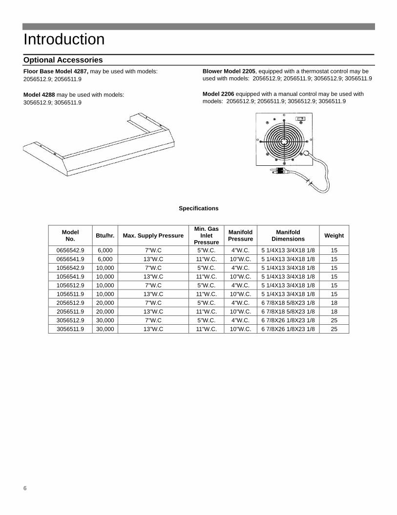
Optional Accessories Floor Base Model 4287, may be used with models: 2056512.9; 2056511.9
Model 4288 may be used with models: 3056512.9; 3056511.9
Blower Model 2205, equipped with a thermostat control may be used with models: 2056512.9; 2056511.9; 3056512.9; 3056511.9
Model 2206 equipped with a manual control may be used with models: 2056512.9; 2056511.9; 3056512.9; 3056511.9
Specifications
Model No. Btu/hr. Max. Supply Pressure
Min. Gas Inlet
Pressure Manifold Pressure
Manifold Dimensions Weight
0656542.9 6,000 7"W.C 5"W.C. 4"W.C. 5 1/4X13 3/4X18 1/8 15 0656541.9 6,000 13"W.C 11"W.C. 10"W.C. 5 1/4X13 3/4X18 1/8 15 1056542.9 10,000 7"W.C 5"W.C. 4"W.C. 5 1/4X13 3/4X18 1/8 15 1056541.9 10,000 13"W.C 11"W.C. 10"W.C. 5 1/4X13 3/4X18 1/8 15 1056512.9 10,000 7"W.C 5"W.C. 4"W.C. 5 1/4X13 3/4X18 1/8 15 1056511.9 10,000 13"W.C 11"W.C. 10"W.C. 5 1/4X13 3/4X18 1/8 15 2056512.9 20,000 7"W.C 5"W.C. 4"W.C. 6 7/8X18 5/8X23 1/8 18 2056511.9 20,000 13"W.C 11"W.C. 10"W.C. 6 7/8X18 5/8X23 1/8 18 3056512.9 30,000 7"W.C 5"W.C. 4"W.C. 6 7/8X26 1/8X23 1/8 25 3056511.9 30,000 13"W.C 11"W.C. 10"W.C. 6 7/8X26 1/8X23 1/8 25
Provisions for Adequate Combustion and Ventilation Air
7
Supplying Adequate Ventilation
The following information will help you provide adequate ventilation. Unusually tight construction is defined as construction where:
a. walls and ceilings exposed to the outside atmosphere have a continuous water vapor retarder with a rating of one perm (6 x 10-11 kg per pa-sec-m2) or less with openings gasketed or sealed and
b. weather stripping has been added on openable windows and doors and
c. caulking or sealants are applied to areas such as joints around window and door frames, between sole plates and floors, between wall-ceiling joints, between wall panels, at penetrations for plumbing, electrical and gas lines and at other openings.
If your home meets all of the three criteria above, you must provide additional fresh air.
WARNING: If the area in which the heater may be operated is of unusually tight construction, provide adequate combustion and ventilation air by one of the methods described in the National Fuel Gas Code, ANSIZ223.1, Section 5.3 or applicable local codes.
Determining If You Need Additional Fresh Air.
Space: Includes the room in which you will install heater plus any adjoining rooms with doorless passageways or ventilation grills between the rooms.
1. Determine the volume of the space (length x width x height). Length x Width x Height=_______cu. ft. (volume of space)
Example: Space size 22 ft. (length) x 18 ft. (width) x 8 ft. (ceiling height) = 3,168 cu. ft. (volume of space) If additional ventilation to adjoining room is supplied with grills or openings, add the volume of these rooms to the total volume of the space.
2. Divide the space volume by 50 cubic feet to determine the maximum Btu/hr the space can support, (volume of space) divided by 50 cu. ft. = (Maximum Btu/hr the space can support.
Example: 3,168 cu. ft. (volume of space) divided by 50 cu. ft. = 63.36 or 63,360 (maximum Btu/hr the space can support)
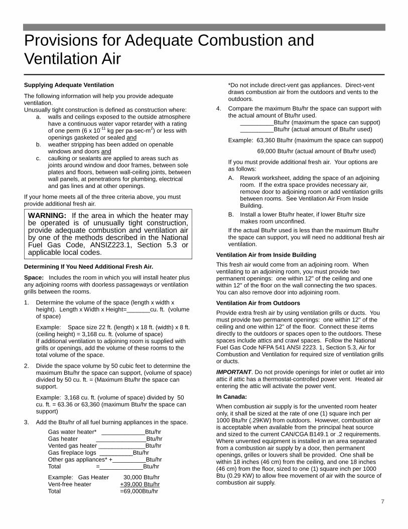
3. Add the Btu/hr of all fuel burning appliances in the space. Gas water heater* _____________Btu/hr Gas heater _______________Btu/hr Vented gas heater ______________Btu/hr Gas fireplace logs __________Btu/hr Other gas appliances* +__________Btu/hr Total =_____________Btu/hr
Example: Gas Heater 30,000 Btu/hr Vent-free heater +39,000 Btu/hr Total =69,000Btu/hr
*Do not include direct-vent gas appliances. Direct-vent draws combustion air from the outdoors and vents to the outdoors.
4. Compare the maximum Btu/hr the space can support with the actual amount of Btu/hr used.
__________Btu/hr (maximum the space can suppot) __________Btu/hr (actual amount of Btu/hr used)
Example: 63,360 Btu/hr (maximum the space can suppot)
69,000 Btu/hr (actual amount of Btu/hr used)
If you must provide additional fresh air. Your options are as follows: A. Rework worksheet, adding the space of an adjoining
room. If the extra space provides necessary air, remove door to adjoining room or add ventilation grills between rooms. See Ventilation Air From Inside Building.
B. Install a lower Btu/hr heater, if lower Btu/hr size makes room unconfined.
If the actual Btu/hr used is less than the maximum Btu/hr the space can support, you will need no additional fresh air ventilation.
Ventilation Air from Inside Building This fresh air would come from an adjoining room. When ventilating to an adjoining room, you must provide two permanent openings: one within 12" of the ceiling and one within 12" of the floor on the wall connecting the two spaces. You can also remove door into adjoining room.
Ventilation Air from Outdoors Provide extra fresh air by using ventilation grills or ducts. You must provide two permanent openings: one within 12" of the ceiling and one within 12" of the floor. Connect these items directly to the outdoors or spaces open to the outdoors. These spaces include attics and crawl spaces. Follow the National Fuel Gas Code NFPA 541 ANSI 2223. 1, Section 5.3, Air for Combustion and Ventilation for required size of ventilation grills or ducts.
IMPORTANT. Do not provide openings for inlet or outlet air into attic if attic has a thermostat-controlled power vent. Heated air entering the attic will activate the power vent.
In Canada: When combustion air supply is for the unvented room heater only, it shall be sized at the rate of one (1) square inch per 1000 Btu/hr (.29KW) from outdoors. However, combustion air is acceptable when available from the principal heat source and sized to the current CAN/CGA B149.1 or .2 requirements. Where unvented equipment is installed in an area separated from a combustion air supply by a door, then permanent openings, grilles or louvers shall be provided. One shall be within 18 inches (46 cm) from the ceiling, and one 18 inches (46 cm) from the floor, sized to one (1) square inch per 1000 Btu (0.29 KW) to allow free movement of air with the source of combustion air supply.
Installing Your Heater
8
Unpack Your Unvented Gas Heater The heater is shipped assembled. The cabinet must be removed for the heater installation.
1. Open carton and carefully lift out heater. 2. Stand heater upright. 3. Hardware included with heater:
(2) metal mounting brackets (4) screws (4) plastic anchors (1) mounting bracket paper template
4. Properly dispose of shipping material.
NOTE
Check the burner rating plate, located inside the cabinet on the bottom, to make sure your heater is equipped to operate on the type of gas available (either Natural or L.P. Gas). DO NOT convert the heater from Natural Gas to L.P. Gas or from L.P. Gas to Natural Gas.
Locating Unvented Gas Heater Consider the following points before attempting to install the heater:
1. This heater is designed to be mounted on a wall. It can also be located on the floor, away from the wall, using an optional floor mounting stand.
2. Select a location for the heater that will provide exposure of the radiant surface to the room, but will not be subjected to accidental contact. Adequate clearance must be available around the air opening.
3. Be sure to read the section "Provisions for Adequate Combustion and Ventilation Air" requirements before
deciding where you install this heater. The heater must have enough fresh air suitable for proper combustion.
4. For proper combustion of the heater, you may need to provide one or more fresh air openings to the room where the heater is located.
5. This heater creates warm air currents that move heat to wall surfaces next to heater. Installing the heater next to vinyl or cloth wall coverings or operating heater where impurities in the air (such as tobacco smoke) exist, may discolor walls.
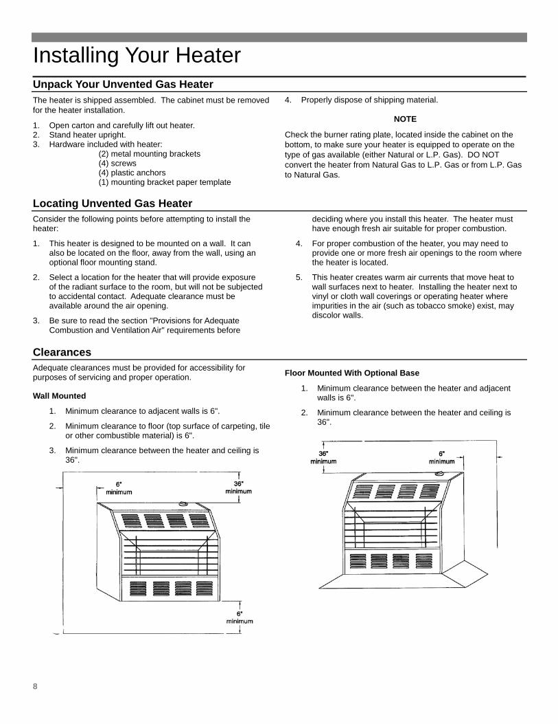
ClearancesAdequate clearances must be provided for accessibility for purposes of servicing and proper operation. Wall Mounted
1. Minimum clearance to adjacent walls is 6".
2. Minimum clearance to floor (top surface of carpeting, tile or other combustible material) is 6".
3. Minimum clearance between the heater and ceiling is 36".
Floor Mounted With Optional Base
1. Minimum clearance between the heater and adjacent walls is 6".
2. Minimum clearance between the heater and ceiling is 36".
Installing Your Heater
9
Installation and repair should be done by a qualified service technician.
An inspection of the heater and attached systems should be performed at least once each year by a qualified service technician. More frequent inspections are advisable if the heater is installed or operated in a manner that might cause the accumulation of dust or dirt in the heater, or the failure of component parts may occur more rapidly than would normally be expected.
In Canada:
Installation must conform with local codes or, in the absence of local codes, with the current standard CAN/CGA - B 149.1 Natural Gas Installation Code or CAN/CGA - B149.2 Propane Installation Code.
If the unvented room heater is installed in a residential garage, the following precautions must be taken.
• The heater pilot and burner must be at least 24-inches above the floor.
• The heater must be located and protected, so as not to be subjected to damage by a moving vehicle.
• All flammable fuels must be removed.
Connect the unvented room heater to the gas supply line as specified by the "Gas Supply and Piping Requirements" section on page 10 of this manual.
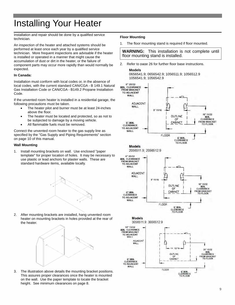
Wall Mounting
1. Install mounting brackets on wall. Use enclosed "paper template" for proper location of holes. It may be necessary to use plastic or lead anchors for plaster walls. These are standard hardware items, available locally.
2. After mounting brackets are installed, hang unvented room
heater on mounting brackets in holes provided at the rear of the heater.
3. The illustration above details the mounting bracket positions.
This assures proper clearances once the heater is mounted on the wall. Use the paper template to locate the bracket height. See minimum clearances on page 8.
Floor Mounting
1. The floor mounting stand is required if floor mounted.
WARNING: This installation is not complete until floor mounting stand is installed.
2. Refer to page 26 for further floor base instructions.
Models 0656541.9; 0656542.9; 1056511.9; 1056512.9 1056541.9; 1056542.9
Installing Your Heater
10
Gas Supply and Piping If you are not sure what type gas is available in your locality, obtain this information from your local gas supply company prior to installing the heater. The pilot and control system of this heater will automatically stop the gas flow to the pilot burner and main burner if the pilot flame is extinguished. This system also generates the electricity required to operate the thermostat system. Since no electrical power is required from any other source, this heater
will continue to operate during a power outage, with the exception of the optional blower kit. If installation is for L.P. Gas, have the L.P. installer use a two-stage regulator and make all connections from storage tank to heater. Use two pipe wrenches when making the connection to the valve to prevent turning or damage to gas valve.
PipingGas pipe must be installed by a qualified installer. The pipe system must comply with local codes and ordinances or with the latest edition of the American National Fuel Gas Code Z223.1.
1. The gas supply line must be of an adequate size to handle the Btu/hr requirements and length of the run for the unit being installed. Determine the minimum pipe size from below table basing the length of the run from the gas meter or source to the unit.
NATURAL GAS PIPE CAPACITY - Btu/hr (INCLUDES FITTINGS)
PIPE SIZE LENGTH OF PIPE-FEET
1/2 INCH
3/4 INCH
1 INCH
20 40 60
92,000 63,000 50,000
190,000 130,000 105,000
350,000 245,000 195,000
L. P. GAS PIPE CAPACITY - Btu/hr (INCLUDES FITTINGS)
PIPE SIZE LENGTH OF PIPE-FEET
1/2 INCH
3/4 INCH
1 INCH
20 40 60
189,000 129,000 103,000
393,000 267,000 217,000
732,000 504,000 409,000
2. Use new, properly reamed pipe free from chips such as steel or black iron pipe and fittings or other approved by local codes.
3. Do not thread pipe too far. Valve distortion or malfunction may result from excess pipe within the control.
4. Use moderate amount of good quality compound to pipe only, leaving 2 end threads bare. If L.P. gas installation, use compound resistant to action of liquefied petroleum gases.
WARNING: All gas piping and connections must be tested for leaks after installation or servicing all leaks must be corrected immediately.
5. Use ground joint unions.
6. Install a drip leg (sediment trap). The drip leg is required to prevent condensate and scale particles from entering the gas valve.
7. Install a manual shut-off valve.
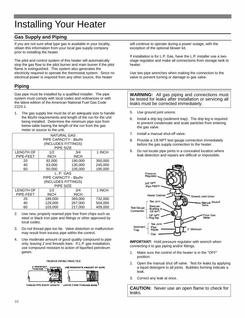
8. Provide a 1/8 NPT test gauge connection immediately before the gas supply connection to the heater.
9. Do not locate pipe joints in a concealed location where leak detection and repairs are difficult or impossible.
IMPORTANT: Hold pressure regulator with wrench when connecting it to gas piping and/or fittings.
1. Make sure the control of the heater is in the "OFF" position.
2. Open the manual shut off valve. Test for leaks by applying a liquid detergent to all joints. Bubbles forming indicate a leak.
3. Correct any leak at once.
CAUTION: Never use an open flame to check for leaks.
Installing Your Heater
11
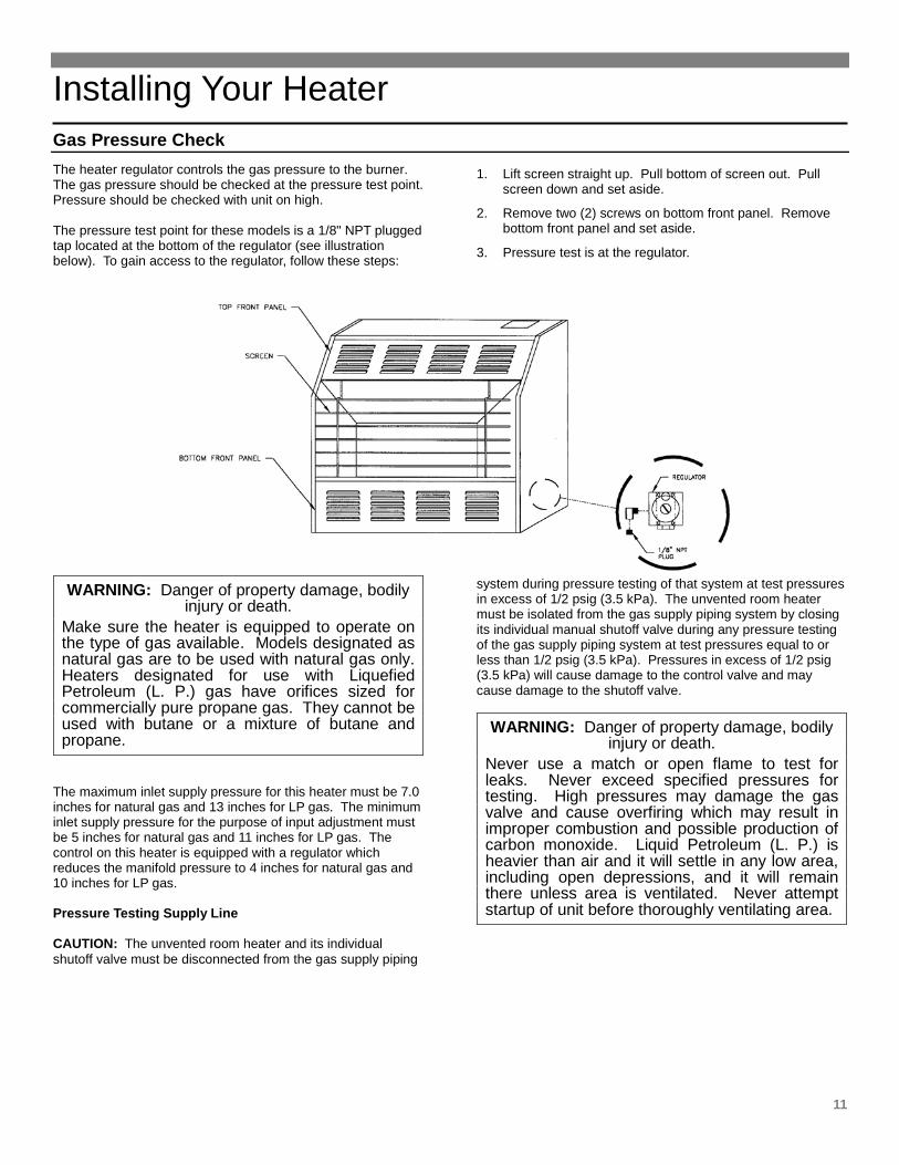
Gas Pressure CheckThe heater regulator controls the gas pressure to the burner. The gas pressure should be checked at the pressure test point. Pressure should be checked with unit on high. The pressure test point for these models is a 1/8" NPT plugged tap located at the bottom of the regulator (see illustration below). To gain access to the regulator, follow these steps:
1. Lift screen straight up. Pull bottom of screen out. Pull screen down and set aside.
2. Remove two (2) screws on bottom front panel. Remove bottom front panel and set aside.
3. Pressure test is at the regulator.
WARNING: Danger of property damage, bodily injury or death.
Make sure the heater is equipped to operate on the type of gas available. Models designated as natural gas are to be used with natural gas only. Heaters designated for use with Liquefied Petroleum (L. P.) gas have orifices sized for commercially pure propane gas. They cannot be used with butane or a mixture of butane and propane.
The maximum inlet supply pressure for this heater must be 7.0 inches for natural gas and 13 inches for LP gas. The minimum inlet supply pressure for the purpose of input adjustment must be 5 inches for natural gas and 11 inches for LP gas. The control on this heater is equipped with a regulator which reduces the manifold pressure to 4 inches for natural gas and 10 inches for LP gas. Pressure Testing Supply Line CAUTION: The unvented room heater and its individual shutoff valve must be disconnected from the gas supply piping
system during pressure testing of that system at test pressures in excess of 1/2 psig (3.5 kPa). The unvented room heater must be isolated from the gas supply piping system by closing its individual manual shutoff valve during any pressure testing of the gas supply piping system at test pressures equal to or less than 1/2 psig (3.5 kPa). Pressures in excess of 1/2 psig (3.5 kPa) will cause damage to the control valve and may cause damage to the shutoff valve.
WARNING: Danger of property damage, bodily injury or death.
Never use a match or open flame to test for leaks. Never exceed specified pressures for testing. High pressures may damage the gas valve and cause overfiring which may result in improper combustion and possible production of carbon monoxide. Liquid Petroleum (L. P.) is heavier than air and it will settle in any low area, including open depressions, and it will remain there unless area is ventilated. Never attempt startup of unit before thoroughly ventilating area.
Installing Your Heater
12
WARNING: Carbon monoxide is a poisonous, combustible gas formed by incomplete combustion. It is colorless, odorless and tasteless. Depending on the length of exposure and the amount inhaled, carbon monoxide can cause – • Dizziness • Headache • Nausea • Bodily injury (brain damage) • Death by asphyxiation If you encounter or suspect that carbon monoxide is present, get fresh air at once and seek medical attention immediately.
WARNING: Improper installation, adjustment, alteration, service or maintenance can cause injury or property damage. Refer to this manual. For assistance or additional information, consult a qualified installer, service agency or the gas supplier.
Operating Your Heater
FOR YOUR SAFETY, READ BEFORE LIGHTING
WARNING: If you do not follow these instructions exactly, a fire or explosion may result causing property damage, personal injury or loss of life.
LIGHTING THE PILOT
A. This appliance is equipped with an ignition device which manually lights the pilot.
B. BEFORE LIGHTING smell all around the appliance area for gas. Be sure to smell next to the floor because some gas is heavier than air and will settle on the floor.
C. WHAT TO DO IF YOU SMELL GAS • Do not try to light any appliance or strike a match. • Do not touch any electric switch; do not use any
phone in your building. • Immediately call your gas supplier from a neighbor's
phone. Follow the gas supplier's instructions
• If you cannot reach your gas supplier, call the fire department.
D. Use only your hand to push in or turn the gas control knob. Never use tools. If the knob will not push in or turn by hand, don't try to repair it, call a qualified service technician. Force or attempted repair may result in a fire or explosion.
E. Do not use this appliance if any part has been under water. Immediately call a qualified service technician to inspect the appliance and to replace any part of the control system and any gas control which has been underwater.
OPERATING INSTRUCTIONS
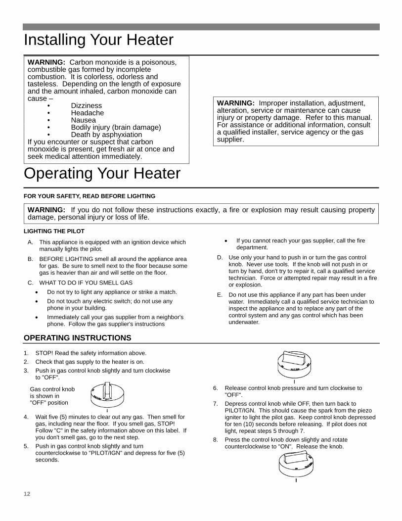
1. STOP! Read the safety information above. 2. Check that gas supply to the heater is on. 3. Push in gas control knob slightly and turn clockwise
to "OFF".
4. Wait five (5) minutes to clear out any gas. Then smell for
gas, including near the floor. If you smell gas, STOP! Follow "C" in the safety information above on this label. If you don't smell gas, go to the next step.
5. Push in gas control knob slightly and turn counterclockwise to "PILOT/IGN" and depress for five (5) seconds.
6. Release control knob pressure and turn clockwise to
"OFF". 7. Depress control knob while OFF, then turn back to
PILOT/IGN. This should cause the spark from the piezo igniter to light the pilot gas. Keep control knob depressed for ten (10) seconds before releasing. If pilot does not light, repeat steps 5 through 7.
8. Press the control knob down slightly and rotate counterclockwise to "ON". Release the knob.
Gas control knob is shown in "OFF" position
Operating Your Heater
13
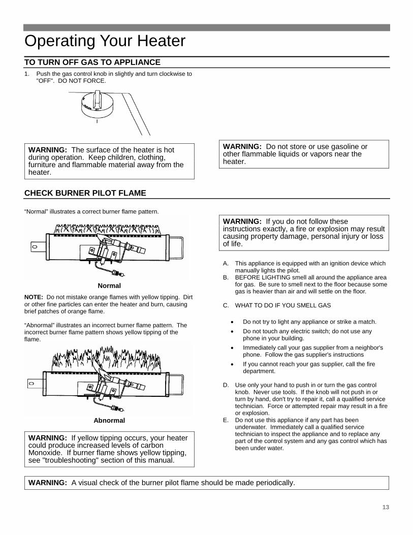
TO TURN OFF GAS TO APPLIANCE 1. Push the gas control knob in slightly and turn clockwise to
"OFF". DO NOT FORCE.
WARNING: The surface of the heater is hot during operation. Keep children, clothing, furniture and flammable material away from the heater.
WARNING: Do not store or use gasoline or other flammable liquids or vapors near the heater.
CHECK BURNER PILOT FLAME “Normal” illustrates a correct burner flame pattern.
Normal
NOTE: Do not mistake orange flames with yellow tipping. Dirt or other fine particles can enter the heater and burn, causing brief patches of orange flame. “Abnormal” illustrates an incorrect burner flame pattern. The incorrect burner flame pattern shows yellow tipping of the flame.
Abnormal
WARNING: If yellow tipping occurs, your heater could produce increased levels of carbon Monoxide. If burner flame shows yellow tipping, see "troubleshooting" section of this manual.
WARNING: If you do not follow these instructions exactly, a fire or explosion may result causing property damage, personal injury or loss of life.
A. This appliance is equipped with an ignition device which
manually lights the pilot. B. BEFORE LIGHTING smell all around the appliance area
for gas. Be sure to smell next to the floor because some gas is heavier than air and will settle on the floor.
C. WHAT TO DO IF YOU SMELL GAS
• Do not try to light any appliance or strike a match. • Do not touch any electric switch; do not use any
phone in your building. • Immediately call your gas supplier from a neighbor's
phone. Follow the gas supplier's instructions • If you cannot reach your gas supplier, call the fire
department.
D. Use only your hand to push in or turn the gas control knob. Never use tools. If the knob will not push in or turn by hand, don't try to repair it, call a qualified service technician. Force or attempted repair may result in a fire or explosion.
E. Do not use this appliance if any part has been underwater. Immediately call a qualified service technician to inspect the appliance and to replace any part of the control system and any gas control which has been under water.
WARNING: A visual check of the burner pilot flame should be made periodically.
Caring for Your Heater
14
WARNING: DANGER OF BODILY INJURY OR DEATH If fan kit accessory is used, turn off electric power supply at disconnect switch, fuse box or service panel before removing any doors or access/service panels from unit.
Annual Upkeep Needed
It is recommended that a qualified service technician inspect the heater annually. Cabinet
Clean cabinet with damp cloth. Never use abrasive cleaners. Cabinets are finished in heat resistant baked enamel. DO NOT refinish with wall paint. ODS Pilot and Burner
Use a vacuum cleaner, pressurized air, or small, soft bristled brush to clean the ODS pilot and burner. Never use a wire, needle or similar object to clean ODS pilot. This could damage the ODS pilot unit.
Service, repair or maintenance of the unvented heating system should only be attempted by a qualified service technician. The burner and control of the heater should be cleaned and
checked at least once each year by a qualified service technician. If there is any indication that the heater is operating improperly, turn it off and have it checked immediately. Lint and dust may be vacuumed from the interior of the heater, when it is cool. The control and main burner can be blown free of dust and lint with a vacuum cleaner or pressurized air. Keep all combustible materials, gasoline and other flammable liquids or vapors away from this heater. Be sure that combustion and ventilation air openings supplying this heater are kept clear at all times. Continued safe and satisfactory performance of this heater requires, but is not limited to, periodic examination of the pilot flame, combustion chamber, liners and gas supply lines, and periodic cleaning of the burner air intake, pilot and control areas.
Inspecting Pilot
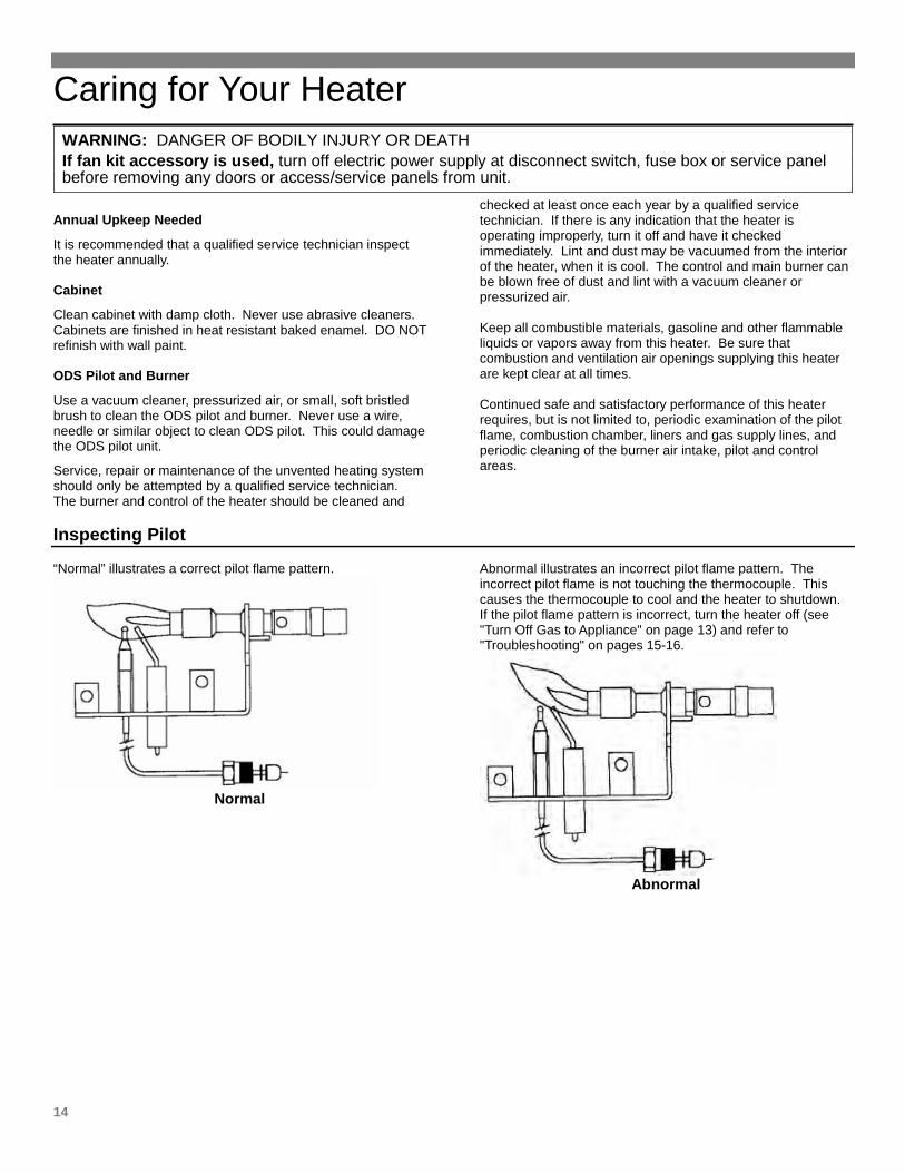
“Normal” illustrates a correct pilot flame pattern.
Normal
Abnormal illustrates an incorrect pilot flame pattern. The incorrect pilot flame is not touching the thermocouple. This causes the thermocouple to cool and the heater to shutdown. If the pilot flame pattern is incorrect, turn the heater off (see "Turn Off Gas to Appliance" on page 13) and refer to "Troubleshooting" on pages 15-16.
Abnormal
Troubleshooting Your Heater
15
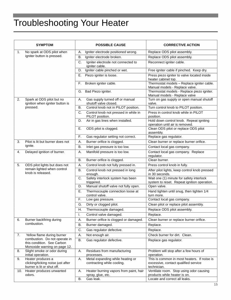
SYMPTOM POSSIBLE CAUSE CORRECTIVE ACTION
1. No spark at ODS pilot when igniter button is pressed.
A. Igniter electrode positioned wrong. Replace ODS pilot assembly. B. Igniter electrode broken. Replace ODS pilot assembly. C. Igniter electrode not connected to
igniter cable. Reconnect igniter cable.
D. Igniter cable pinched or wet. Free igniter cable if pinched. Keep dry. E. Piezo igniter is loose. Press piezo igniter to valve located inside
heater cabinet top. F. Broken igniter cable. Thermostat models – Replace igniter cable.
Manual models - Replace valve. G. Bad Piezo igniter. Thermostat models - Replace piezo igniter.
Manual models - Replace valve 2. Spark at ODS pilot but no
ignition when igniter button is pressed.
A. Gas supply turned off or manual shutoff valve closed.
Turn on gas supply or open manual shutoff valve.
B. Control knob not in PILOT position. Turn control knob to PILOT position. C. Control knob not pressed in while in
PILOT position. Press in control knob while in PILOT position.
D. Air in gas lines when installed. Hold down control knob. Repeat igniting operation until air is removed.
E. ODS pilot is clogged. Clean ODS pilot or replace ODS pilot assembly.
F. Gas regulator setting not correct. Replace gas regulator. 3. Pilot is lit but burner does not
ignite. A. Burner orifice is clogged. Clean burner or replace burner orifice. B. Inlet gas pressure is too low. Contact local gas company.
4. Delayed ignition of burner. A. Manifold pressure is too low. Contact local gas company. Replace regulator.
B. Burner orifice is clogged. Clean burner. 5. ODS pilot lights but does not
remain lighted when control knob is released.
A. Control knob not fully pressed in. Press control knob in fully. B. Control knob not pressed in long
enough. After pilot lights, keep control knob pressed in 30 seconds.
C. Safety interlock system has been triggered.
Wait one (1) minute for safety interlock system to reset. Repeat ignition operation.
D. Manual shutoff valve not fully open. Open valve. E. Thermocouple connection loose at
control valve. Hand tighten until snug, then tighten 1/4 turn more.
F. Low gas pressure. Contact local gas company. G. Dirty or clogged pilot. Clean pilot or replace pilot assembly. H. Thermocouple damaged. Replace ODS pilot assembly. I. Control valve damaged. Replace.
6. Burner backfiring during combustion.
A. Burner orifice is clogged or damaged. Clean burner or replace burner orifice. B. Burner damaged. Replace. C. Gas regulator defective. Replace.
7. Yellow flame during burner combustion. Do not operate in this condition. See Carbon Monoxide warning on page 12.
A. Not enough air. Check burner for dirt. Clean. B. Gas regulator defective. Replace gas regulator.
8. Slight smoke or odor during initial operation.
A. Residues from manufacturing processes.
Problem will stop after a few hours of operation.
9. Heater produces a clicking/ticking noise just after burner is lit or shut off.
A. Metal expanding while heating or contracting while cooling.
This is common in most heaters. If noise is excessive, contact qualified service technician.
10. Heater produces unwanted odors.
A. Heater burning vapors from paint, hair spray, glue, etc.
Ventilate room. Stop using odor causing products while heater is on.
B. Gas leak. Locate and correct all leaks.
Troubleshooting Your Heater
16
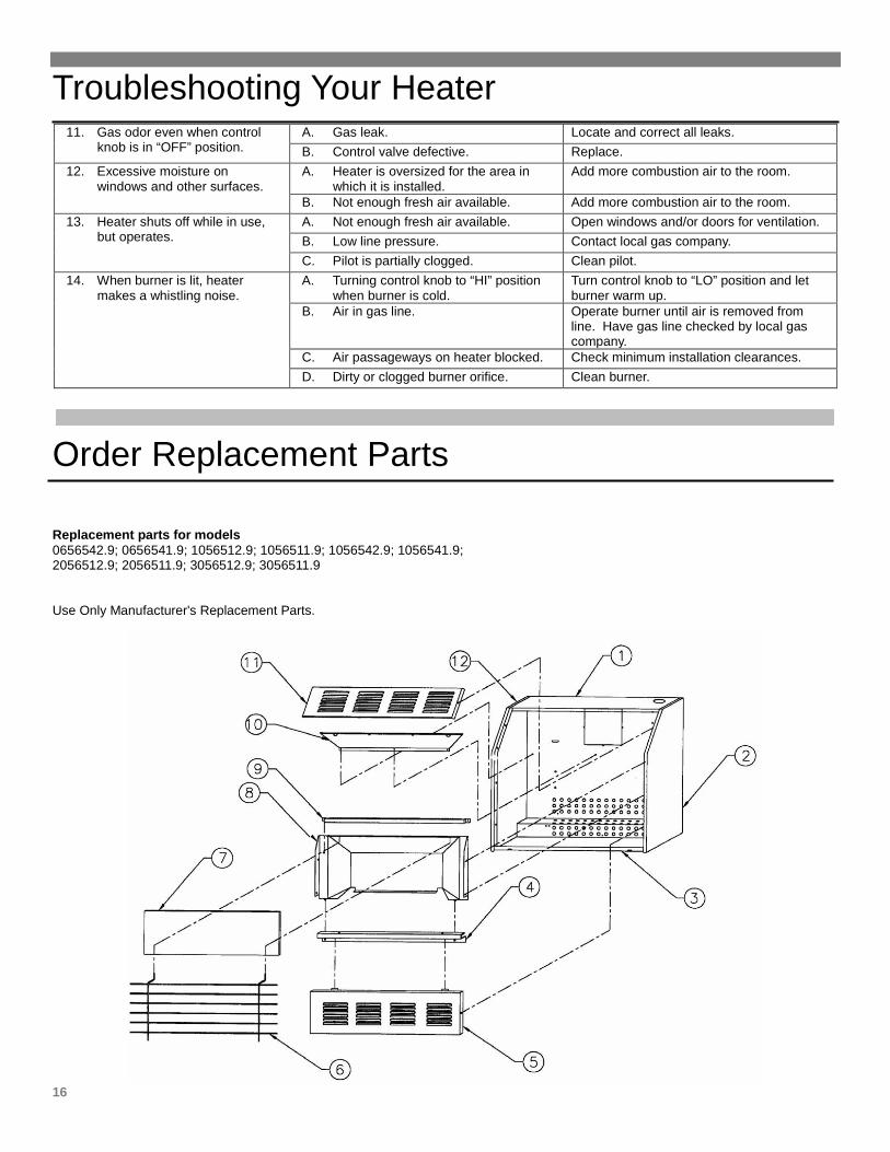
11. Gas odor even when control knob is in “OFF” position.
A. Gas leak. Locate and correct all leaks. B. Control valve defective. Replace.
12. Excessive moisture on windows and other surfaces.
A. Heater is oversized for the area in which it is installed.
Add more combustion air to the room.
B. Not enough fresh air available. Add more combustion air to the room. 13. Heater shuts off while in use,
but operates. A. Not enough fresh air available. Open windows and/or doors for ventilation. B. Low line pressure. Contact local gas company. C. Pilot is partially clogged. Clean pilot.
14. When burner is lit, heater makes a whistling noise.
A. Turning control knob to “HI” position when burner is cold.
Turn control knob to “LO” position and let burner warm up.
B. Air in gas line. Operate burner until air is removed from line. Have gas line checked by local gas company.
C. Air passageways on heater blocked. Check minimum installation clearances. D. Dirty or clogged burner orifice. Clean burner.
Order Replacement Parts Replacement parts for models 0656542.9; 0656541.9; 1056512.9; 1056511.9; 1056542.9; 1056541.9; 2056512.9; 2056511.9; 3056512.9; 3056511.9 Use Only Manufacturer's Replacement Parts.
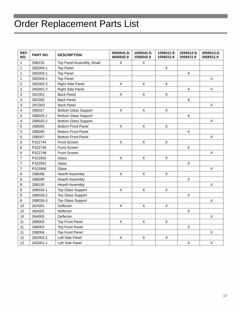
Order Replacement Parts List
17
REF. NO. PART NO. DESCRIPTION 0656541.9;
0656542.9 1056541.9; 1056542.9
1056511.9; 1056512.9
2056512.9; 2056511.9
3056512.9; 3056511.9
1 26B155 Top Panel Assembly, Small X X 1 26D005-1 Top Panel X 1 26D003-1 Top Panel X 1 26D004-1 Top Panel X 2 26D002-2 Right Side Panel X X X 2 26D001-2 Right Side Panel X X 3 26C001 Back Panel X X X 3 26C002 Back Panel X 3 26C003 Back Panel X 4 26B027 Bottom Glass Support X X X 4 26B025-1 Bottom Glass Support X 4 26B025-2 Bottom Glass Support X 5 26B005 Bottom Front Panel X X X 5 26B006 Bottom Front Panel X 5 26B007 Bottom Front Panel X 6 P322744 Front Screen X X X 6 P322746 Front Screen X 6 P322748 Front Screen X 7 P322902 Glass X X X 7 P322901 Glass X 7 P322900 Glass X 8 26B098 Hearth Assembly X X X 8 26B099 Hearth Assembly X 8 26B100 Hearth Assembly X 9 26B026-1 Top Glass Support X X X 9 26B026-2 Top Glass Support X 9 26B026-3 Top Glass Support X 10 26A001 Deflector X X X 10 26A002 Deflector X 10 26A003 Deflector X 11 26B002 Top Front Panel X X X 11 26B003 Top Front Panel X 11 26B004 Top Front Panel X 12 26D002-1 Left Side Panel X X X 12 26D001-1 Left Side Panel X X
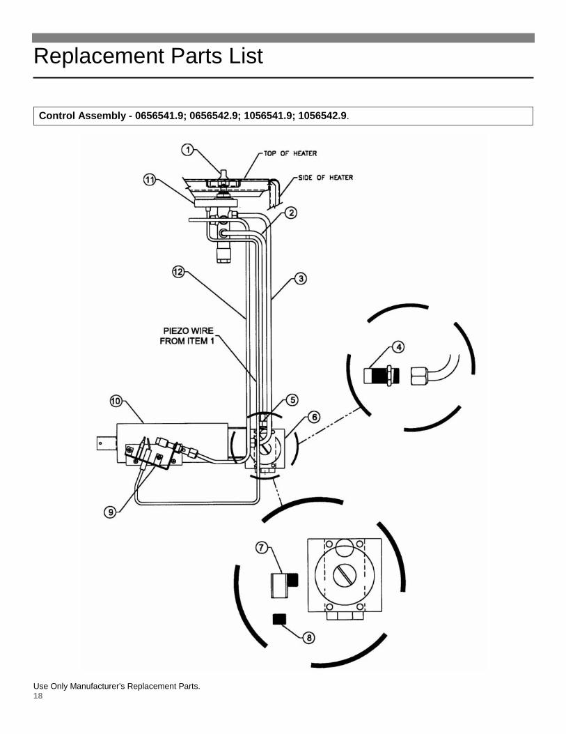
Replacement Parts List
18
Control Assembly - 0656541.9; 0656542.9; 1056541.9; 1056542.9.
Use Only Manufacturer's Replacement Parts.
Order Replacement Parts
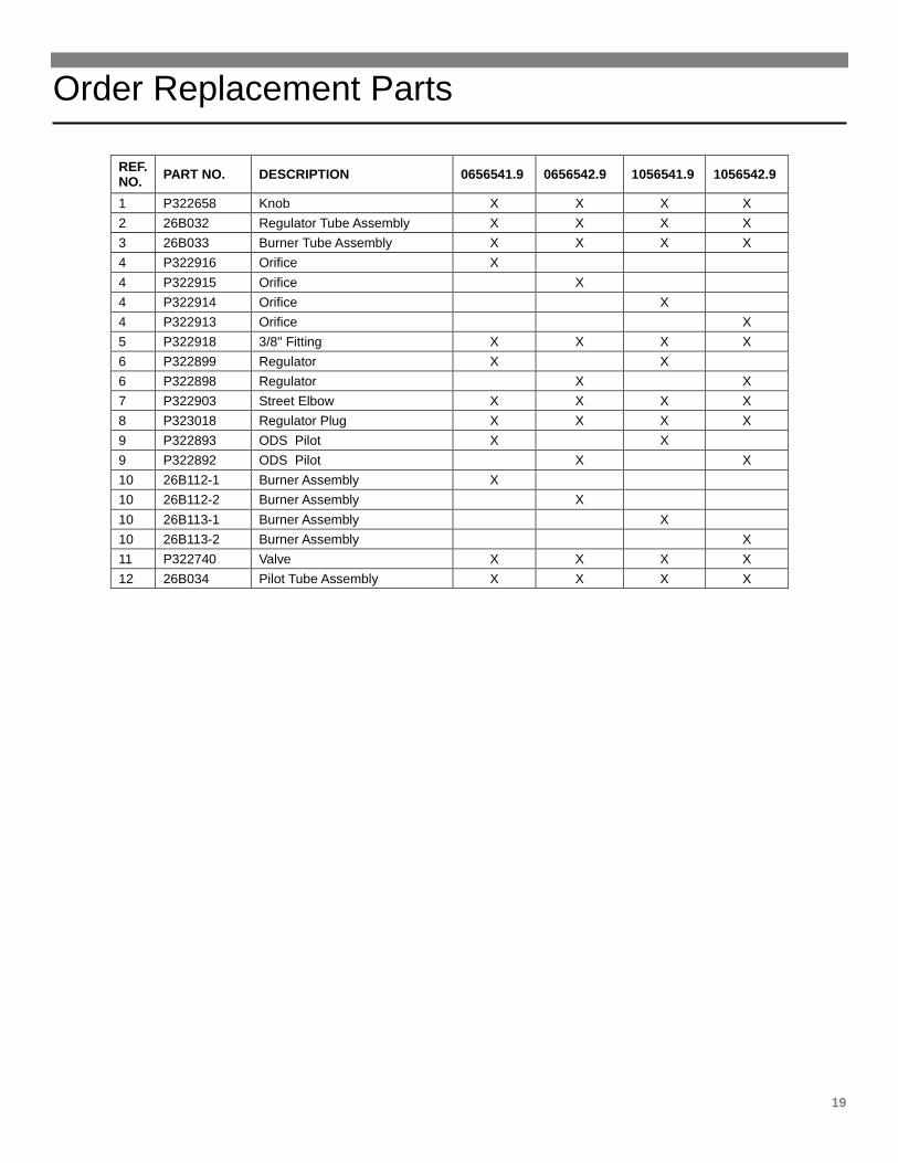
19
Service and Orders – 19
REF. NO. PART NO. DESCRIPTION 0656541.9 0656542.9 1056541.9 1056542.9
1 P322658 Knob X X X X 2 26B032 Regulator Tube Assembly X X X X 3 26B033 Burner Tube Assembly X X X X 4 P322916 Orifice X 4 P322915 Orifice X 4 P322914 Orifice X 4 P322913 Orifice X 5 P322918 3/8" Fitting X X X X 6 P322899 Regulator X X 6 P322898 Regulator X X 7 P322903 Street Elbow X X X X 8 P323018 Regulator Plug X X X X 9 P322893 ODS Pilot X X 9 P322892 ODS Pilot X X 10 26B112-1 Burner Assembly X 10 26B112-2 Burner Assembly X 10 26B113-1 Burner Assembly X 10 26B113-2 Burner Assembly X 11 P322740 Valve X X X X 12 26B034 Pilot Tube Assembly X X X X
Replacement Parts List
20
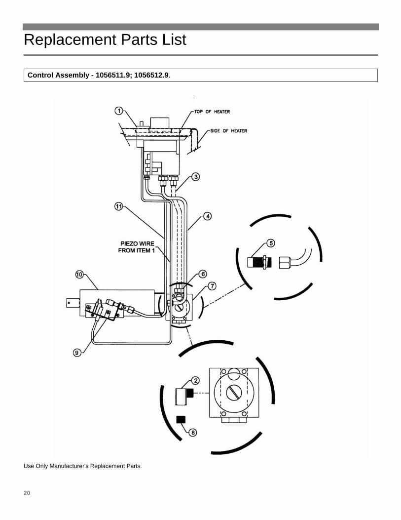
Control Assembly - 1056511.9; 1056512.9.
Use Only Manufacturer's Replacement Parts.
Order Replacement Parts
21
Service and Orders – 21
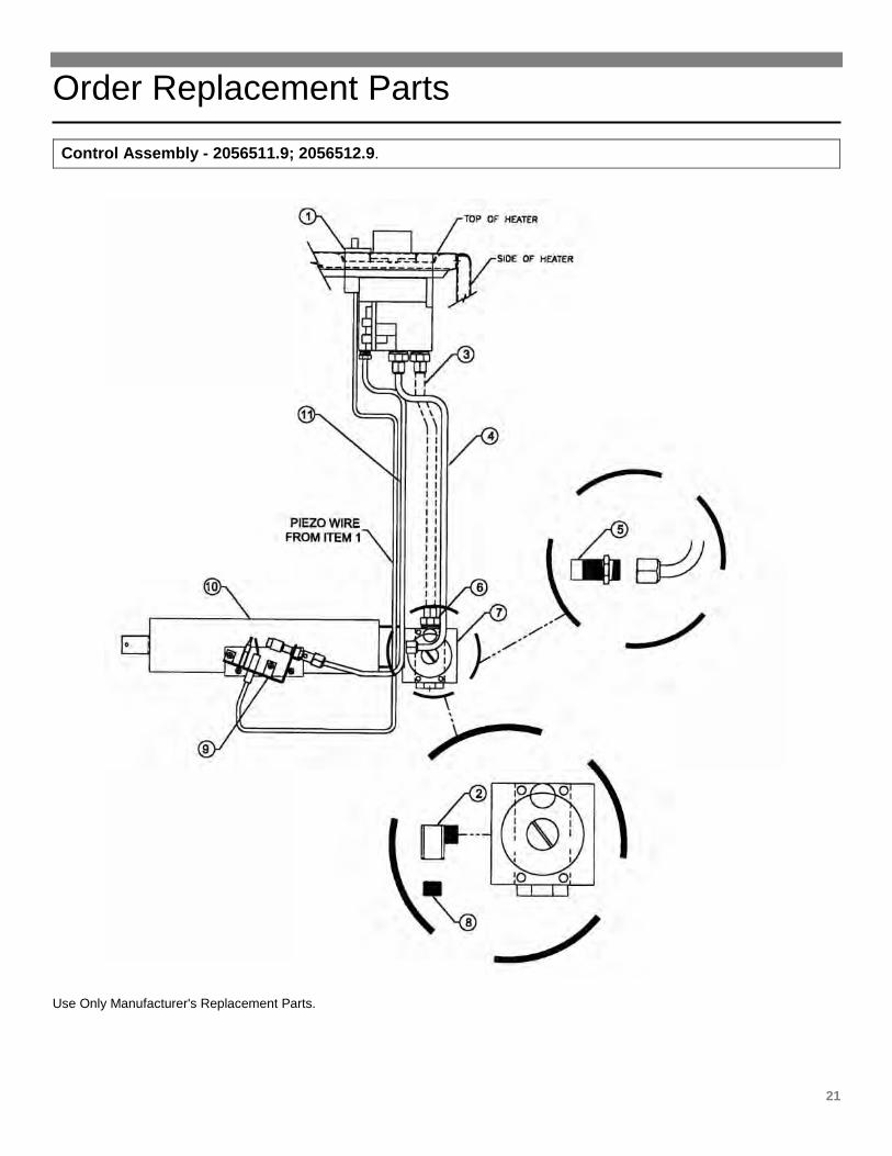
Control Assembly - 2056511.9; 2056512.9.
Use Only Manufacturer's Replacement Parts.
Order Replacement Parts
22
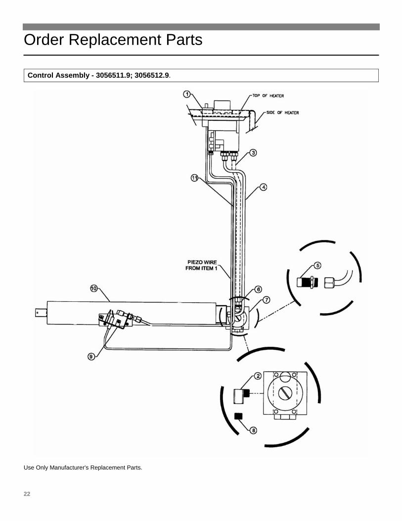
Control Assembly - 3056511.9; 3056512.9.
Use Only Manufacturer's Replacement Parts.
Replacement Parts
23
Service and Orders – 23
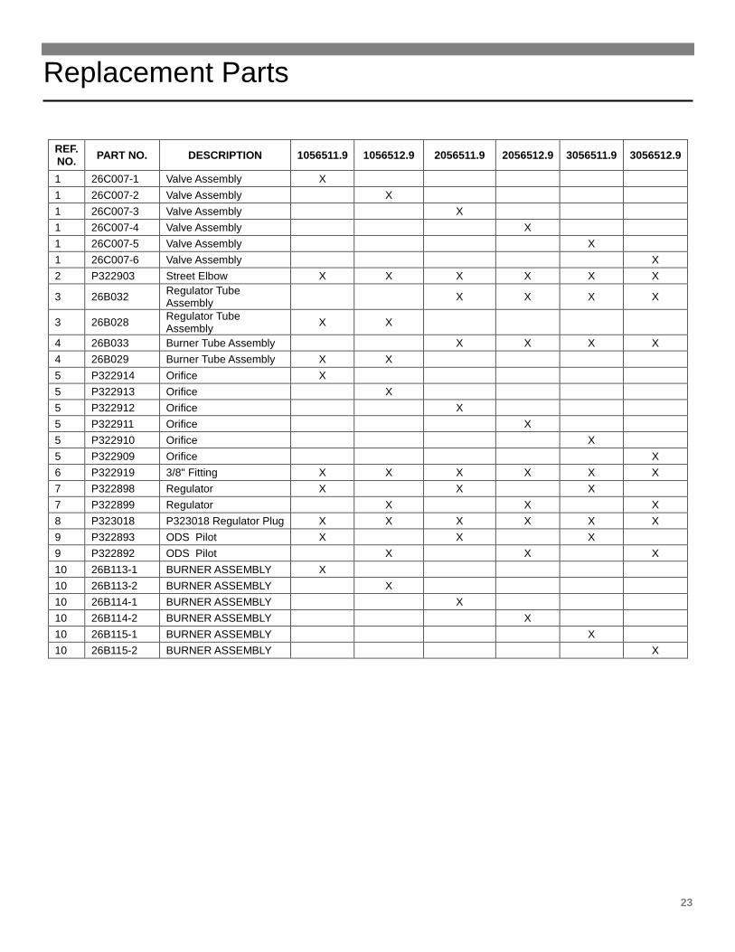
REF. NO. PART NO. DESCRIPTION 1056511.9 1056512.9 2056511.9 2056512.9 3056511.9 3056512.9
1 26C007-1 Valve Assembly X 1 26C007-2 Valve Assembly X 1 26C007-3 Valve Assembly X 1 26C007-4 Valve Assembly X 1 26C007-5 Valve Assembly X 1 26C007-6 Valve Assembly X 2 P322903 Street Elbow X X X X X X
3 26B032 Regulator Tube Assembly X X X X
3 26B028 Regulator Tube Assembly X X
4 26B033 Burner Tube Assembly X X X X 4 26B029 Burner Tube Assembly X X 5 P322914 Orifice X 5 P322913 Orifice X 5 P322912 Orifice X 5 P322911 Orifice X 5 P322910 Orifice X 5 P322909 Orifice X 6 P322919 3/8" Fitting X X X X X X 7 P322898 Regulator X X X 7 P322899 Regulator X X X 8 P323018 P323018 Regulator Plug X X X X X X 9 P322893 ODS Pilot X X X 9 P322892 ODS Pilot X X X 10 26B113-1 BURNER ASSEMBLY X 10 26B113-2 BURNER ASSEMBLY X 10 26B114-1 BURNER ASSEMBLY X 10 26B114-2 BURNER ASSEMBLY X 10 26B115-1 BURNER ASSEMBLY X 10 26B115-2 BURNER ASSEMBLY X
Installing and Operating Your Blower Accessory
24
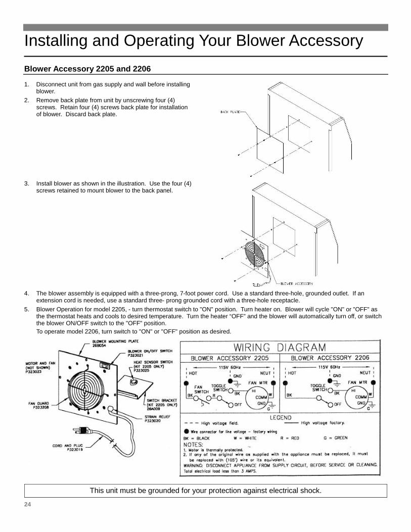
Blower Accessory 2205 and 2206
1. Disconnect unit from gas supply and wall before installing blower.
2. Remove back plate from unit by unscrewing four (4) screws. Retain four (4) screws back plate for installation of blower. Discard back plate.
3. Install blower as shown in the illustration. Use the four (4)
screws retained to mount blower to the back panel.
4. The blower assembly is equipped with a three-prong, 7-foot power cord. Use a standard three-hole, grounded outlet. If an
extension cord is needed, use a standard three- prong grounded cord with a three-hole receptacle. 5. Blower Operation for model 2205, - turn thermostat switch to "ON" position. Turn heater on. Blower will cycle "ON" or "OFF" as
the thermostat heats and cools to desired temperature. Turn the heater “OFF” and the blower will automatically turn off, or switch the blower ON/OFF switch to the "OFF" position. To operate model 2206, turn switch to "ON" or "OFF" position as desired.
This unit must be grounded for your protection against electrical shock.
Installing and Operating Your Blower Accessory
25
Service and Orders – 25
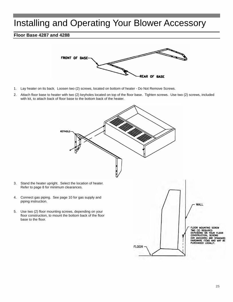
Floor Base 4287 and 4288
1. Lay heater on its back. Loosen two (2) screws, located on bottom of heater - Do Not Remove Screws.
2. Attach floor base to heater with two (2) keyholes located on top of the floor base. Tighten screws. Use two (2) screws, included with kit, to attach back of floor base to the bottom back of the heater.
3. Stand the heater upright. Select the location of heater.
Refer to page 8 for minimum clearances.
4. Connect gas piping. See page 10 for gas supply and piping instruction.
5. Use two (2) floor mounting screws, depending on your floor construction, to mount the bottom back of the floor base to the floor.
26
In addition to the Installation and Operating Instruction Manual packaged with this unvented heater, all installations in the State of Massachusetts must use the following requirements when installing, maintaining or operating unvented propane or natural gas-fired space heaters. 527 CMR 30.00 UNVENTED PROPANE OR NATURAL GAS-FIRED SPACE HEATERS Section 30.01: Purpose 30.02: Scope 30.03: Definitions 30.04: Installation 30.04: Maintenance and Operation 30.01: Purpose
The purpose of 527 CMR 30.00 is to provide requirements for the installation, maintenance, and operation of unvented propane or natural gas fired space heaters.
30.02: Scope
527 CMR 30.00 shall apply to unvented propane natural gas-fired space heaters installed in occupancies used in whole or in part for habitation on or after April 1, 2004. 527 CMR 30.00 shall not apply to unvented propane or natural gas-fired space heaters used in habituated spaces or those installed in accordance with 527 CMR 20.
30.03: Definition
Malfunction, shall mean condition where a space heater fails to operate properly as provided in the manufacturer's instructions.
Oxygen Depletion Safety Shutoff System (ODS): A device utilized to shut off the gas supply to the pilot or main burner when the oxygen in the surrounding atmosphere is depleted to the percent concentration developed by the manufacturer, but under no circumstances shall the concentration be less than 18 percent oxygen concentration.
Primary Heat: A heat source that is permanently installed and used exclusively to provide heat to the entire structure (e.g. forced hot water, forced hot air) by means of a central heater or boiler which has a permanent fuel source (e.g. oil, natural gas or LPG) or electric heat. 527 CMR 30.03. Primary Heat shall not include fireplaces or wood stoves.
Unvented Natural or Propane Gas-Fired Space Heater: A permanently installed stand alone gas-fired unvented room heater or gas-fired unvented decorative room heater for connection to the house fuel supply system which utilizes natural gas or propane. Unvented gas-fired space heaters may be used only for supplemental heat and/or decorative purposes and under no circumstances shall they provide a primary heat source. Unvented gas-fired space heaters shall comply with ANSI Standard Z21.11.2 - 2000 edition, Volume II.
30.04: Installation
1. A permit shall be obtained from the head of the fire department and the local or state gas inspector having jurisdiction for the installation of all unvented propane or natural gas-fired space heaters. Said permits shall be conditioned upon final inspection and approval of installation by the head of the fire department and the local or state gas inspector having jurisdiction. A copy of the manufacturer’s installation/operating literature shall be submitted with each permit application. Before operation, the Head of the Fire Department and the local or state gas inspector shall inspect the installation for compliance with 527 CMR and 248 CMR (Board of State Examiners of Plumbers and Gas Fitters).
2. Unvented propane or natural gas-fired space heaters shall conform to ANSI Z21.11.2, be equipped with an oxygen depletion safety (ODS) shutoff system and be listed and approved in accordance with 248 CMR.
3. Unvented propane or natural gas-fired space heaters shall be installed in accordance with their listings and the manufacturer's instructions. Proper clearances to combustibles shall be maintained. In no case shall the clearances be such as to interfere with combustion air and accessibility.
4. Installations shall be of a permanent type, with a permanently piped fuel supply in accordance with 248 CMR. LPG appliances shall be subject the storage requirements in accordance with 527 CMR 6.00. Portable unvented propane or natural gas-fired space heaters shall be prohibited.
5. Unvented propane or natural gas-fired space heaters shall be prohibited in bedrooms and bathrooms.
6. Space heaters shall be properly sized for the room or space of installation, but shall not exceed a maximum of 40,000 Btu/hr input per room or space.
7. In occupancies with an unvented propane or natural gas-fired space heater; at least one listed carbon monoxide detector shall be installed and maintained in any room or space where said heater has been installed in accordance with the manufacturer’s instructions. Any building wherein said heater is to be installed shall, as a precondition to such installation, have working smoke detectors installed and maintained in accordance with the requirements of 780 CMR
27
Service and Orders – 27
(State Board of Building Regulations and Standards) in effect at the time of construction or if no said requirement was in effect at the time of construction, installed as provided for in M.G.L.c 148, §26E.
8. In rooms and buildings served by an unvented propane or natural gas-fired space heater, a primary source of heat which is operable, shall be permanently installed and maintained in said building in accordance with 105 CMR (Department of Public Health).
9. Seller of unvented propane or natural gas-fired space heaters shall provide to each purchaser a copy of 527 CMR 30.00 upon sale of the unit.
30.05: Maintenance and Operation
1. The maintenance and operation of unvented propane or natural gas-fired space heaters shall be in accordance with the manufacturer’s instructions. The manufacturer’s instructions shall be left with the appliance and made available for any public official.
2. Any malfunction of an unvented space heater shall forthwith be reported by the owner to the-head of the local fire department.
REGULATORY AUTHORITY
527 CMR 30.00 M.G.L.c. 148, §25E
Hints and Information
28
Service Hints If your unvented heater fails to work correctly, you may avoid inconvenience and the cost of a service call by checking the troubleshooting section on pages 15 and 16 before you call for service.
– Do not store or use gasoline or other flammable
vapors and liquids in the vicinity of this or any other appliance.
– This appliance should be inspected before use and at least once a year by a qualified service person. Installation and repairs must be done by a qualified service person.
– What to do if you smell gas • Open all windows • Do not try to light any appliance. • Do not touch any electrical switch; do not use
any phone in your building. • Extinguish any open flame. • Immediately call your gas supplier, call the
fire department. • Installation and service must be performed by
a qualified installer, service agency or the gas supplier.
How to Order Repair Parts When ordering repair parts, always give the following Information:
1. Model number
2. Serial number
3. Part number
4. Part description
All parts listed herein may be ordered from your equipment supplier. The model number of your Williams unvented gas heater will be found on the nameplate near gas valve, inside control compartment.
WARNING: If the information in this manual is not followed exactly, a fire or explosion may result causing property damage, personal injury or loss of life.
Williams Furnace Company • 250 West Laurel Street, Colton, CA 92324 (909) 825-0993 • FAX: (909) 824-8009
Manufactured in the U.S.A. • Established 1916 P923665 October 2014 ALL RIGHTS RESERVED