Embed Size (px)
Citation preview
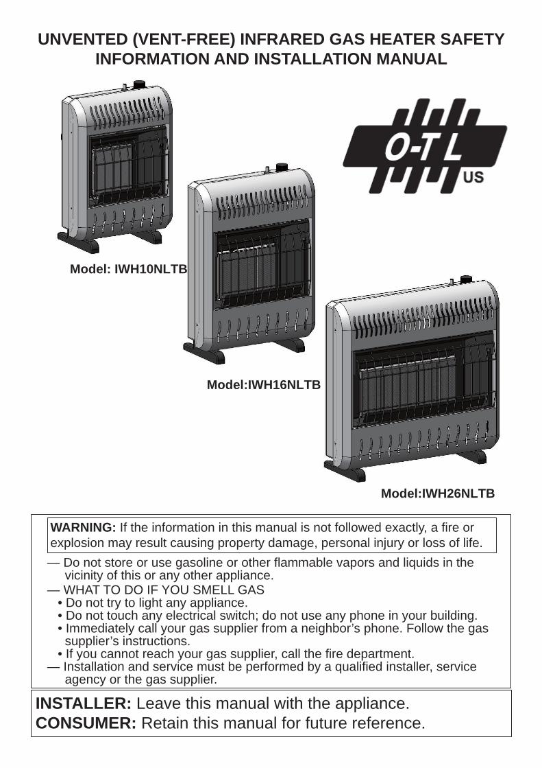
UNVENTED (VENT-FREE) INFRARED GAS HEATER SAFETY INFORMATION AND INSTALLATION MANUAL
INSTALLER: Leave this manual with the appliance.CONSUMER: Retain this manual for future reference.
— Do not store or use gasoline or other fl ammable vapors and liquids in the vicinity of this or any other appliance.— WHAT TO DO IF YOU SMELL GAS • Do not try to light any appliance. • Do not touch any electrical switch; do not use any phone in your building. • Immediately call your gas supplier from a neighbor’s phone. Follow the gas supplier’s instructions. • If you cannot reach your gas supplier, call the fi re department.— Installation and service must be performed by a qualifi ed installer, service agency or the gas supplier.
WARNING: If the information in this manual is not followed exactly, a fi re or explosion may result causing property damage, personal injury or loss of life.
Model: IWH10NLTB
Model:IWH16NLTB
Model:IWH26NLTB
2
TABLE OF CONTENTSSafety Information .................................................2Local Codes........................................................... 4Product Identifi cation ............................................ 4Unpacking.............................................................. 4Product Features................................................... 4Air For Combustion and Ventilation ...................... 5Installation............................................................. 7Operating Heater .................................................17Inspecting Heater ................................................19
Cleaning and Maintenance .................................20Troubleshooting.................................................. 21Specifi cations ..................................................... 24Wiring Diagrams ................................................. 24Service Hints ...................................................... 24Replacement Parts ............................................. 24Technical Service................................................ 28Service Publications ........................................... 28Warranty Information ...........................Back Cover
SAFETY INFORMATION
WARNING: Improper insta-llation, adjustment, alterat-ion, service or maintenan-ce can cause injury or pro-perty damage. Refer to this manual for correct install-ation and operationalprocedures. For assistanceor additional information consult a qualifi ed installerservice agency or the gas supplier.
WARNING: This is an unve-nted gas fi red heater. It uses air (oxygen) from the room in which it is installed. Provisions for adequate combustion and ventilation air must be provided. Refer to Air for Combustion and Ventilation section on page 5 of this manual.
This appliance is only for use withthe type of gas indicated on the rating plate. This appliance is notconvertible for use with other gases.
This appliance may be installed in an aftermarket,*permanently located, manufactured (mobile) home, where not prohibited by local codes.
* Aftermarket: Completion of sale, not for purpose of resale, from the manufacturer
WARNING: This product contains and/or generates chemicals known to the State of California to cause cancer or birth defects or other reproductive harm.
IMPORTANT: Read this owner’smanual carefully and completelybefore trying to assemble, operate or service this heater. Improper use of this heater can cause serious injury or death from burns, fi re, explosion, electrical shock and carbon monoxide poisoning.
3
SAFETY INFORMATIONContinued
Carbon Monoxide Poisoning: Early signsof carbon monoxide poisoning resemble thefl u, with headaches, dizziness or nausea. Ifyou have these signs, the heater may notbe working properly. Get fresh air at once!Have heater serviced. Some people aremore affected by carbon monoxide than oth-ers. These include pregnant women, peoplewith heart or lung disease or anemia, thoseunder the infl uence of alcohol and those athigh altitudes.Natural and Propane/LP Gas: Natural andPropane/LP gases are odorless. An odor-making agent is added to these gases. Theodor helps you detect a gas leak. However,the odor added to the gas can fade. Gas maybe present even though no odor exists.Make certain you read and understand allwarnings. Keep this manual for reference. Itis your guide to safe and proper operation ofthis heater.
Due to high temperatures, the appliance should be located out of traffi c and away from furniture and draperies.
WARNING: Do not use a blower insert, heat exchanger insert or other accessory not approved for use with this heater.
DANGER: Carbon monoxidepoisoning may lead to death!
WARNING: Any change to this heater or its controls can be dangerous.
Do not place clothing or otherfl ammable material on or near the appliance. Never place any objects on the heater.
Surface of heater becomes very hot when running heater. Keep children and adults away from hot surface to avoid burns or clothing ignition. Heater will remain hot for a time after shutdown. Allow surface to cool before touching.
Carefully supervise young children when they are in the same room with heater.Make sure grill guard is in placebefore running heater.
Keep the appliance area clear and free from combustible materials, gasoline and other fl ammable vapors and liquids.
This appliance is only for use with the 1. type of gas indicated on the rating plate. Thisappliance is not convertible for use with other gases.Do not place propane/LP supply tank(s) 2. inside any structure. Locate propane/LP supply tank(s) outdoors.For room heater having an input rating in 3. excess of 6000 BTU/hr (1758W), this heater shall not be installed in a bathroom. For room heater having an input rating in excess of 10,000 BTU/hr (2931W), this heater shall not be installed in a bedroom or bathroom. If you smell gas4. • shut off gas supply• do not try to light any appliance• do not touch any electrical switch; do not use any phone in your building• immediately call your gas supplier from a neighbor’s phone. Follow the gas supplier’s instructions• if you cannot reach your gas supplier, call the fi re departmentThis heater needs fresh, outside air ventila-5. tion to run properly. This heater has an Oxy-gen Depletion Sensing (ODS) safety shutoff system. The ODS shuts down the heater if not enough fresh air is available. See Air for Combustion and Ventilation, page 5.Keep all air openings in front and bottom 6. of heater clear and free of debris. This will ensure enough air for proper combustion.If heater shuts off, do not relight until you 7. provide fresh, outside air. If heater keeps shutting off, have it serviced.
SAFETY INFORMATIONContinued
8. If heater shuts off, do not relight until you provide fresh, outside air. If heater keeps shutting off, have it serviced.9. Do not run heater • where fl ammable liquids or vapors are used or stored • under dusty conditions10. Do not use heater if any part has been under water. Call a qualifi ed service tech- nician immediately to inspect the room heater. If necessary, replace some parts of the control system and some parts of the gas control which has been under water.11. Turn off and unplug heater and let cool before servicing. Only a qualifi ed service person should service and repair heater.12. Operating heater above elevations of 4,500 feet (1,371 m) could cause pilot outage.13. To prevent performance problems, do not use propane/LP fuel tank of less than 100 lbs. (45 kg) capacity.14. Before using furniture polish, wax, carpet cleaner or similar products, turn heater off. If heated, the vapors from these products may create a white powder residue within burner box or on adjacent walls or furniture.15. Provide adequate clearances around air openings.
LOCAL CODESInstall and use heater with care. Follow alllocal codes. In the absence of local codes,use the latest edition of The National FuelGas Code, ANSI Z223.1/NFPA 54*.*Available from:American National Standards Institute, Inc.
1430 Broadway New York, NY 10018
National Fire Protection Association, Inc.Batterymarch ParkQuincy, MA 02269
4
State of Massachusetts: The installationmust be made by a licensed plumber or gasfi tter in the Commonwealth of Massachusetts.Sellers of unvented propane or natural gas-fi red supplemental room heaters shall provide to each purchaser a copy of 527 CMR 30 upon sale of the unit.Vent-free gas products are prohibited for bedroom and bathroom installation in theCommonwealth of Massachusetts.
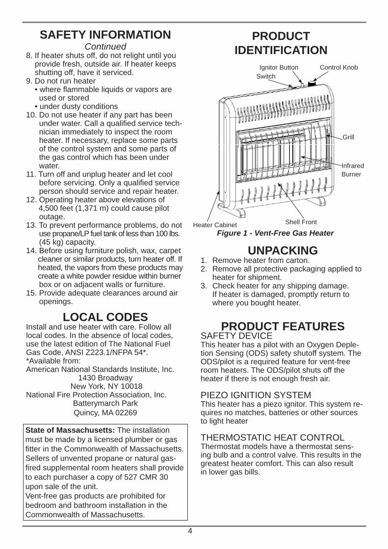
PRODUCTIDENTIFICATION
UNPACKINGRemove heater from carton.1. Remove all protective packaging applied to 2. heater for shipment.Check heater for any shipping damage. 3. If heater is damaged, promptly return to where you bought heater.
PRODUCT FEATURESSAFETY DEVICEThis heater has a pilot with an Oxygen Deple-tion Sensing (ODS) safety shutoff system. TheODS/pilot is a required feature for vent-freeroom heaters. The ODS/pilot shuts off theheater if there is not enough fresh air.
PIEZO IGNITION SYSTEMThis heater has a piezo ignitor. This system re-quires no matches, batteries or other sourcesto light heater
THERMOSTATIC HEAT CONTROLThermostat models have a thermostat sens-ing bulb and a control valve. This results in thegreatest heater comfort. This can also resultin lower gas bills.
Figure 1 - Vent-Free Gas Heater
Control KnobIgnitor Button
Grill
Infrared Burner
Heater Cabinet Shell Front
Switch
5
AIR FOR COMBUSTION AND VENTILATION
Today’s homes are built more energy effi cientthan ever. New materials, increased insulationand new construction methods help reduceheat loss in homes. Home owners weatherstrip and caulk around windows and doorsto keep the cold air out and the warm air in.During heating months, home owners wanttheir homes as airtight as possible.While it is good to make your home energyeffi cient, your home needs to breathe. Freshair must enter your home. All fuel-burning ap-pliances need fresh air for proper combustionand ventilation.Exhaust fans, fi replaces, clothes dryers andfuel burning appliances draw air from the house to operate. You must provide adequate fresh air for these appliances. This will ensure proper venting of vented fuel-burning appliances.
PROVIDING ADEQUATEVENTILATIONThe following are excerpts from National FuelGas Code, ANSI Z223.1/NFPA 54, Section5.3, Air for Combustion and Ventilation.All spaces in homes fall into one of the threefollowing ventilation classifications:1. Unusually Tight Construction2. Unconfined Space3. Confined SpaceThe information on pages 5 through 7 will help you classify your space and provide adequate ventilation.
WARNING: This heater shallnot be installed in a confi ned space or unusually tight construction unless provisions are provided for adequate combustion and ventilation air. Read the following instructions to ensure proper fresh air for this and other fuel-burning appliances in your home.
Unusually Tight ConstructionThe air that leaks around doors and windowsmay provide enough fresh air for combustionand ventilation. However, in buildings of un-usually tight construction, you must provideadditional fresh air.Unusually tight construction is defi ned asconstruction where:a. walls and ceilings exposed to the outside atmosphere have a continuous water vapor retarder with a rating of one perm (6 x 10-11 kg per pa-sec-m ) or less with openings gasketed or sealed andb. weather stripping has been added on openable windows and doors andc. caulking or sealants are applied to areas such as joints around window and door frames, between sole plates and fl oors, between wall-ceiling joints, between wall panels, at penetrations for plumbing, electrical and gas lines and at other openings.If your home meets all of these three criteria,you must provide additional fresh air. SeeVentilation Air From Outdoors, page 7.If your home does not meet all of the threecriteria above, proceed to Determining Fresh-Air Flow For Heater Location, page 6.
Confi ned and Unconfi ned SpaceThe National Fuel Gas Code, ANSI Z223.1/NFPA 54 defi nes a confi ned space as a spacewhose volume is less than 50 cubic feet per1,000 Btu per hour (4.8 m per kw) of the ag-gregate input rating of all appliances installedin that space and an unconfi ned space as aspace whose volume is not less than 50 cubicfeet per 1,000 Btu per hour (4.8 m per kw)of the aggregate input rating of all appliancesinstalled in that space. Rooms communicatingdirectly with the space in which the appliancesare installed*, through openings not furnishedwith doors, are considered a part of the un-confi ned space.* Adjoining rooms are communicating only ifthere are doorless passageways or ventilationgrills between them.
6
DETERMINING FRESH-AIR FLOWFOR HEATER LOCATION
Determining if you Have a Confined orUnconfined SpaceUse this work sheet to determine if you havea confined or unconfined space.Space: Includes the room in which you will install heater plus any adjoining rooms with doorless passageways or ventilation grills between the rooms.
WARNING: If the area in whichthe heater may be operated is smaller than that defi ned as an unconfi ned space or if the building is of unusually tight construction, provide adequatecombustion and ventilation air by one of the methods described in the National Fuel Gas Code, ANSI Z223.1/NFPA 54 Section 5.3 or applicable local codes.
_______ Btu/Hr (maximum can support) _______ Btu/Hr (actual amount)Example: 51,200 Btu/Hr (maximum the space can support) 60,000 Btu/Hr (actual amount of Btu/Hr used)The space in the above example is a confi nedspace because the actual Btu/Hr used is morethan the maximum Btu/Hr the space can sup-port. You must provide additional fresh air. Youroptions are as follows:A. Rework worksheet, adding the space of an adjoining room. If the extra space provides an unconfi ned space, remove door to adjoin- ing room or add ventilation grills between rooms. See Ventilation Air From Inside Building, page 7.B. Vent room directly to the outdoors. See Ventilation Air From Outdoors, page 7.C. Install a lower Btu/Hr heater, if lower Btu/Hr size makes room unconfi ned.If the actual Btu/Hr used is less than the maxi-mum Btu/Hr the space can support, the space isan unconfi ned space. You will need no additionalfresh air ventilation.
AIR FOR COMBUSTION AND VENTILATION
Continued
1. Determine the volume of the space (length x width x height). Length x Width x Height =__________cu. ft. (volume of space) Example: Space size 20 ft. (6.1 m) (length) x 16 ft. (4.88 m) (width) x 8 ft. (2.44 m) (ceiling height) =2560 cu. ft. (72.49 m ) (volume of space) If additional ventilation to adjoining room is supplied with grills or openings, add the volume of these rooms to the total volume of the space.2 . Multiply the space volume by 20 to determine the maximum Btu/Hr the space can support. ________ (volume of space) x 20 = (Maxi- mum Btu/Hr the space can support) Example: 2560 cu. ft. (72.49 m ) (volume of space) x 20 = 51,200 (maximum Btu/Hr the space can support)3 . Add the Btu/Hr of all fuel burning appliances in the space. Vent-free heater ____________Btu/Hr Gas water heater* ____________Btu/Hr Gas furnace ____________Btu/Hr Vented gas heater ____________Btu/Hr Gas fi replace logs ____________Btu/Hr Other gas appliances* + ___________Btu/Hr Total = ___________Btu/Hr * Do not include direct-vent gas appliances. Direct-vent draws combustion air from the outdoors and vents to the outdoors. Example: Gas water heater 40,000 Btu/Hr Vent-free heater + 20,000 Btu/Hr Total = 60,000 Btu/Hr4. Compare the maximum Btu/Hr the space can support with the actual amount of Btu/Hr used.
VENTILATION AIR
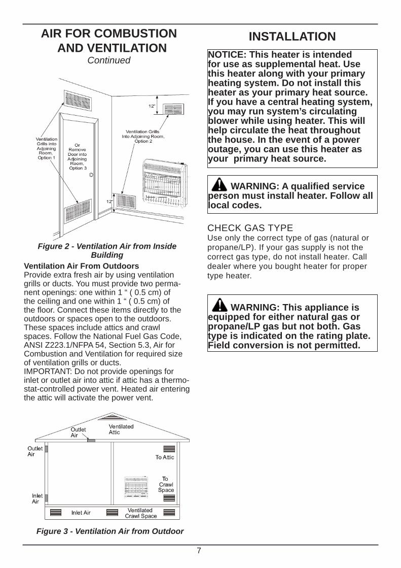
Ventilation Air From Inside BuildingThis fresh air would come from an adjoining unconfi ned space. When ventilating to an adjoining unconfi ned space, you must provide two permanent openings: one within 12” ( 0.5 cm) of the ceiling and one within 12” (30.5 cm) of the fl oor on the wall connecting the two spaces (see options 1 and 2, Figure 2, page 7). You can also remove door into adjoining room (see option 3, Figure 2, page 7). Follow the National Fuel Gas Code, ANSI Z223.1/NFPA 54, Section 5.3, Air for Combustion and Ventilation for required size of ventilation grills or ducts.
7
AIR FOR COMBUSTION AND VENTILATION
Continued
INSTALLATION
Ventilation Air From OutdoorsProvide extra fresh air by using ventilationgrills or ducts. You must provide two perma-nent openings: one within 1 “ ( 0.5 cm) ofthe ceiling and one within 1 “ ( 0.5 cm) ofthe fl oor. Connect these items directly to theoutdoors or spaces open to the outdoors.These spaces include attics and crawlspaces. Follow the National Fuel Gas Code,ANSI Z223.1/NFPA 54, Section 5.3, Air forCombustion and Ventilation for required sizeof ventilation grills or ducts.IMPORTANT: Do not provide openings forinlet or outlet air into attic if attic has a thermo-stat-controlled power vent. Heated air enteringthe attic will activate the power vent.
Figure 2 - Ventilation Air from InsideBuilding
Figure 3 - Ventilation Air from Outdoor
NOTICE: This heater is intended for use as supplemental heat. Use this heater along with your primary heating system. Do not install this heater as your primary heat source. If you have a central heating system, you may run system’s circulating blower while using heater. This will help circulate the heat throughout the house. In the event of a power outage, you can use this heater as your primary heat source.
CHECK GAS TYPEUse only the correct type of gas (natural orpropane/LP). If your gas supply is not thecorrect gas type, do not install heater. Calldealer where you bought heater for propertype heater.
WARNING: This appliance isequipped for either natural gas or propane/LP gas but not both. Gas type is indicated on the rating plate. Field conversion is not permitted.
WARNING: A qualifi ed service person must install heater. Follow all local codes.
8
INSTALLATIONContinued CAUTION: If you install the
heater in a home garage• heater pilot and burner must be at least 18” (45.7 cm) above fl oor• locate heater where moving vehicle will not hit it
CAUTION: This heater creates warm air currents. These currents move heat to wall surfaces next to heater. Installing heater next to vinyl or cloth wall coverings or operating heater where impurities (such as, but not limited to, tobacco smoke, aromatic candles, cleaning fl uids, oil or kerosene lamps, etc.) in the air exist, may discolor walls or cause odors.
IMPORTANT: Vent-free heaters add moisture tothe air. Although this is benefi cial, installing heaterin rooms without enough ventilation air may causemildew to form from too much moisture. See Air for Combustion and Ventilation, page 5. If high humidity is experienced, a dehumidifi er may be used to help lower the water vapor content in the air. For convenience and effi ciency, install heater• where there is easy access for operation, inspection and service• in coldest part of roomTo use fan, locate heater near an electricaloutlet.
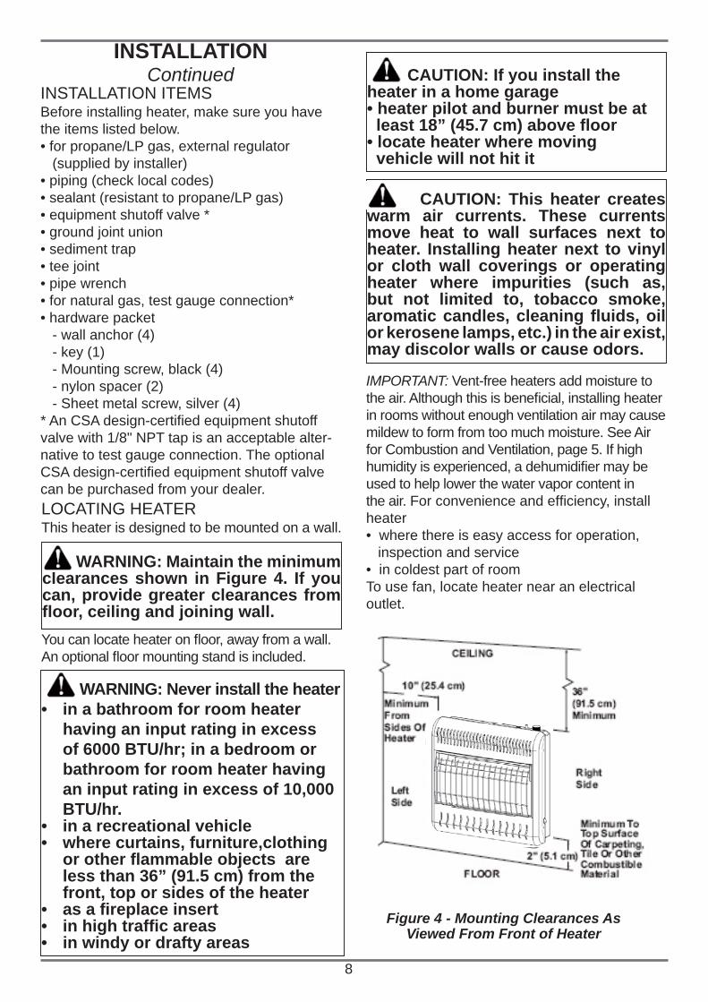
Figure 4 - Mounting Clearances As Viewed From Front of Heater
INSTALLATION ITEMSBefore installing heater, make sure you havethe items listed below.• for propane/LP gas, external regulator (supplied by installer)• piping (check local codes)• sealant (resistant to propane/LP gas)• equipment shutoff valve *• ground joint union• sediment trap• tee joint• pipe wrench• for natural gas, test gauge connection*• hardware packet - wall anchor (4) - key (1) - Mounting screw, black (4) - nylon spacer (2) - Sheet metal screw, silver (4) * An CSA design-certifi ed equipment shutoffvalve with 1/8" NPT tap is an acceptable alter-native to test gauge connection. The optionalCSA design-certifi ed equipment shutoff valvecan be purchased from your dealer.LOCATING HEATERThis heater is designed to be mounted on a wall.
You can locate heater on fl oor, away from a wall. An optional fl oor mounting stand is included.
WARNING: Maintain the minimum clearances shown in Figure 4. If you can, provide greater clearances from fl oor, ceiling and joining wall.
WARNING: Never install the heaterin a bathroom for room heater • having an input rating in excess of 6000 BTU/hr; in a bedroom or bathroom for room heater having an input rating in excess of 10,000 BTU/hr.in a recreational vehicle• where curtains, furniture,clothing • or other fl ammable objects are less than 36” (91.5 cm) from the front, top or sides of the heateras a fi replace insert• in high traffi c areas• in windy or drafty areas•
INSTALLATIONContinued
9
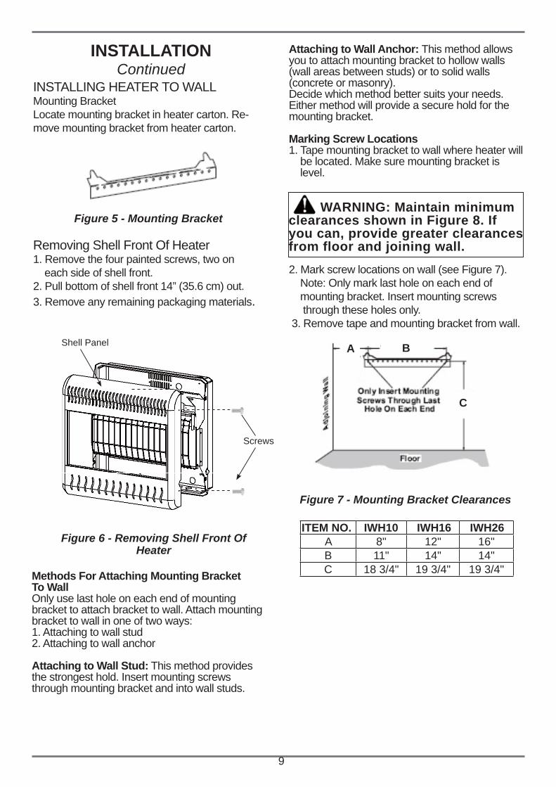
INSTALLING HEATER TO WALLMounting BracketLocate mounting bracket in heater carton. Re-move mounting bracket from heater carton.
Figure 5 - Mounting Bracket
Removing Shell Front Of Heater1. Remove the four painted screws, two on each side of shell front.2. Pull bottom of shell front 14” (35.6 cm) out.3. Remove any remaining packaging materials.
Methods For Attaching Mounting BracketTo WallOnly use last hole on each end of mounting bracket to attach bracket to wall. Attach mounting bracket to wall in one of two ways:1. Attaching to wall stud2. Attaching to wall anchor
Attaching to Wall Stud: This method providesthe strongest hold. Insert mounting screws through mounting bracket and into wall studs.
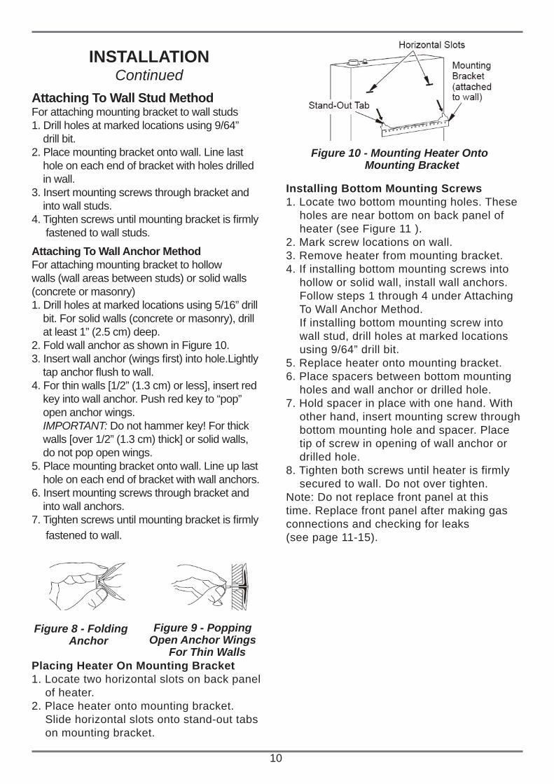
2. Mark screw locations on wall (see Figure 7). Note: Only mark last hole on each end of mounting bracket. Insert mounting screws through these holes only. 3. Remove tape and mounting bracket from wall.
Figure 6 - Removing Shell Front OfHeater
Figure 7 - Mounting Bracket Clearances
WARNING: Maintain minimum clearances shown in Figure 8. If you can, provide greater clearances from floor and joining wall.
Shell Panel
Screws
A B
C
ITEM NO. IWH10 IWH16 IWH26A 8" 12" 16"B 11" 14" 14"C 18 3/4" 19 3/4" 19 3/4"
Attaching to Wall Anchor: This method allows you to attach mounting bracket to hollow walls (wall areas between studs) or to solid walls (concrete or masonry).Decide which method better suits your needs.Either method will provide a secure hold for the mounting bracket.
Marking Screw Locations1. Tape mounting bracket to wall where heater will be located. Make sure mounting bracket is level.
10
Attaching To Wall Stud MethodFor attaching mounting bracket to wall studs1. Drill holes at marked locations using 9/64” drill bit.2. Place mounting bracket onto wall. Line last hole on each end of bracket with holes drilled in wall.3. Insert mounting screws through bracket and into wall studs.4. Tighten screws until mounting bracket is fi rmly fastened to wall studs.
Attaching To Wall Anchor MethodFor attaching mounting bracket to hollow walls (wall areas between studs) or solid walls (concrete or masonry)1. Drill holes at marked locations using 5/16” drill bit. For solid walls (concrete or masonry), drill at least 1” (2.5 cm) deep.2. Fold wall anchor as shown in Figure 10.3. Insert wall anchor (wings fi rst) into hole.Lightly tap anchor fl ush to wall.4. For thin walls [1/2” (1.3 cm) or less], insert red key into wall anchor. Push red key to “pop” open anchor wings. IMPORTANT: Do not hammer key! For thick walls [over 1/2” (1.3 cm) thick] or solid walls, do not pop open wings.5. Place mounting bracket onto wall. Line up last hole on each end of bracket with wall anchors.6. Insert mounting screws through bracket and into wall anchors.7. Tighten screws until mounting bracket is fi rmly fastened to wall.
INSTALLATIONContinued
Placing Heater On Mounting Bracket1. Locate two horizontal slots on back panel of heater.2. Place heater onto mounting bracket. Slide horizontal slots onto stand-out tabs on mounting bracket.
Figure 8 - Folding Anchor
Figure 9 - PoppingOpen Anchor Wings
For Thin Walls
Installing Bottom Mounting Screws1. Locate two bottom mounting holes. These holes are near bottom on back panel of heater (see Figure 11 ).2. Mark screw locations on wall.3. Remove heater from mounting bracket.4. If installing bottom mounting screws into hollow or solid wall, install wall anchors. Follow steps 1 through 4 under Attaching To Wall Anchor Method. If installing bottom mounting screw into wall stud, drill holes at marked locations using 9/64” drill bit.5. Replace heater onto mounting bracket.6. Place spacers between bottom mounting holes and wall anchor or drilled hole.7. Hold spacer in place with one hand. With other hand, insert mounting screw through bottom mounting hole and spacer. Place tip of screw in opening of wall anchor or drilled hole.8. Tighten both screws until heater is firmly secured to wall. Do not over tighten.Note: Do not replace front panel at this time. Replace front panel after making gas connections and checking for leaks(see page 11-15).
Figure 10 - Mounting Heater Onto Mounting Bracket
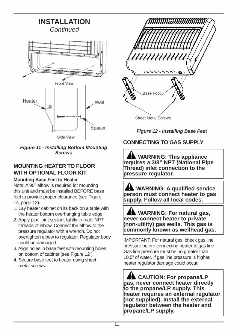
MOUNTING HEATER TO FLOORWITH OPTIONAL FLOOR KITMounting Base Feet to HeaterNote: A 90° elbow is required for mountingthis unit and must be installed BEFORE basefeet to provide proper clearance (see Figure14, page 12).1. Lay heater cabinet on its back on a table with the heater bottom overhanging table edge.2. Apply pipe joint sealant lightly to male NPT threads of elbow. Connect the elbow to the pressure regulator with a wrench. Do not overtighten elbow to regulator. Regulator body could be damaged.3. Align holes in base feet with mounting holes on bottom of cabinet (see Figure 12 ).4. Secure base feet to heater using sheet metal screws.
INSTALLATIONContinued
11
Figure 12 - Installing Base Feet
Figure 11 - Installing Bottom MountingScrews
Base Foot
Sheet Metal Screws
CONNECTING TO GAS SUPPLY
WARNING: This appliancerequires a 3/8” NPT (National Pipe Thread) inlet connection to the pressure regulator.
WARNING: A qualifi ed serviceperson must connect heater to gas supply. Follow all local codes.
WARNING: For natural gas,never connect heater to private(non-utility) gas wells. This gas is commonly known as wellhead gas.
IMPORTANT: For natural gas, check gas linepressure before connecting heater to gas line.Gas line pressure must be no greater than10.5” of water. If gas line pressure is higher,heater regulator damage could occur.
CAUTION: For propane/LPgas, never connect heater directly to the propane/LP supply. This heater requires an external regulator (not supplied). Install the external regulator between the heater and propane/LP supply.
12
Typical Inlet Pipe Diameters -3/8” or greater
Installation must include equipment shutoff valve, union and plugged 1/8” NPT tap. LocateNPT tap within reach for test gauge hook up.NPT tap must be upstream from heater (seeFigure 14).IMPORTANT: Install an equipment shutoff valve in an accessible location. The equipment shutoff valve is for turning on or shutting off the gas to the appliance.Apply pipe joint sealant lightly to male NPT threads. This will prevent excess sealant fromgoing into pipe. Excess sealant in pipe could result in clogged heater valves.
INSTALLATIONContinued
WARNING: Use pipe jointsealant that is resistant to liquidpetroleum (LP) gas.
CAUTION: Use only new, black iron or steel pipe. Internally-tinned copper tubing may be used in certain areas. Check your local codes. Use pipe of large enough diameter to allow proper gas volume to heater. Ifpipe is too small, undue loss ofvolume will occur.
Install sediment trap in supply line as shownin Figure 15. Locate sediment trap where itis within reach for cleaning. Locate sedimenttrap where trapped matter is not likely tofreeze. A sediment trap traps moisture andcontaminants. This keeps them from goinginto heater controls. If sediment trap is notinstalled or is installed wrong, heater maynot run properly.IMPORTANT: Hold the pressure regulatorwith wrench when connecting it to gas pip-ing and/or fittings. Do not over tighten pipeconnection to regulator. The regulator bodycould be damaged.
WARNING: Test all gas pipingand connections, internal andexternal to unit, for leaks afterinstalling or servicing. Correctall leaks at once.
WARNING: Never use an open fl ame to check for a leak. Apply a noncorrosive leak detection fl uid to all joints. Bubbles forming show a leak. Correct all leaks at once.
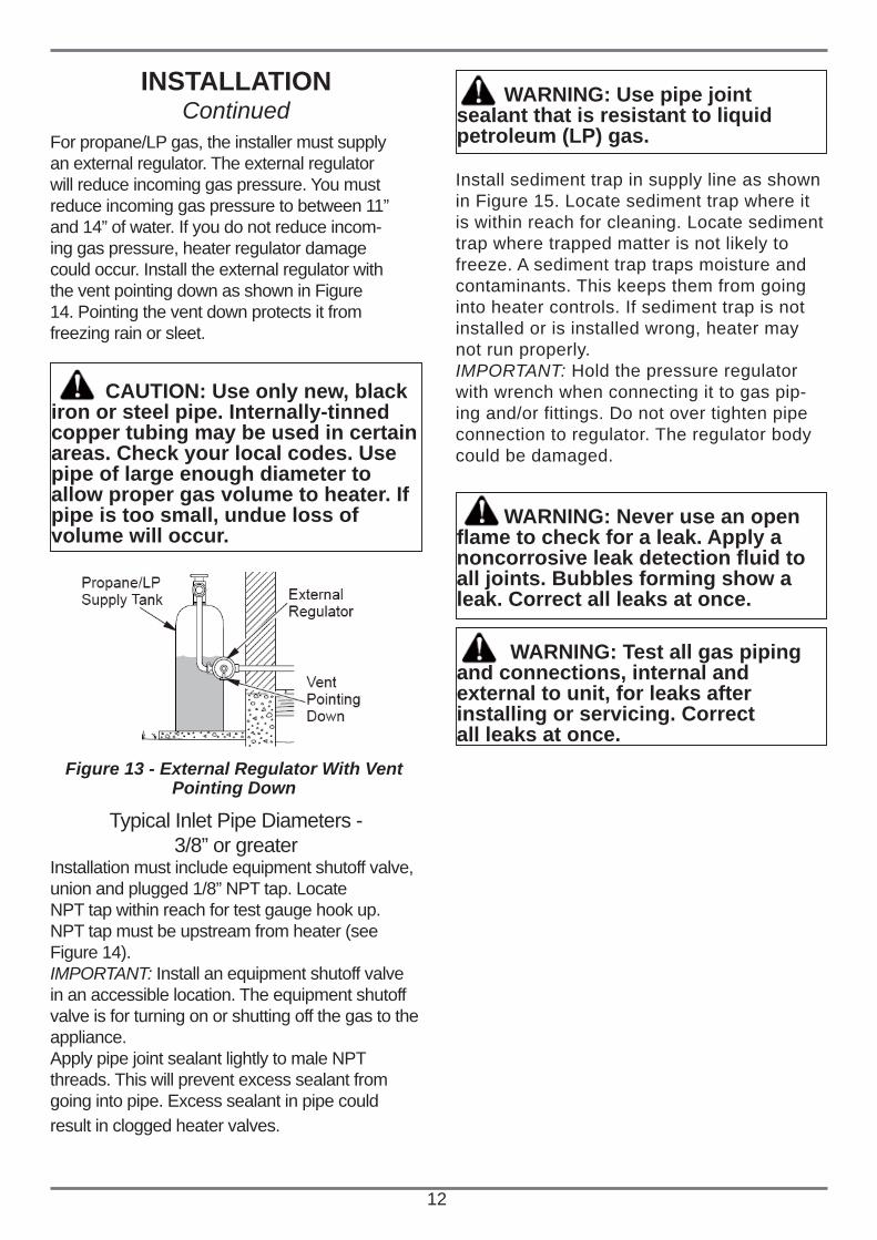
Figure 13 - External Regulator With Vent Pointing Down
For propane/LP gas, the installer must supplyan external regulator. The external regulatorwill reduce incoming gas pressure. You mustreduce incoming gas pressure to between 11”and 14” of water. If you do not reduce incom-ing gas pressure, heater regulator damagecould occur. Install the external regulator withthe vent pointing down as shown in Figure14. Pointing the vent down protects it fromfreezing rain or sleet.
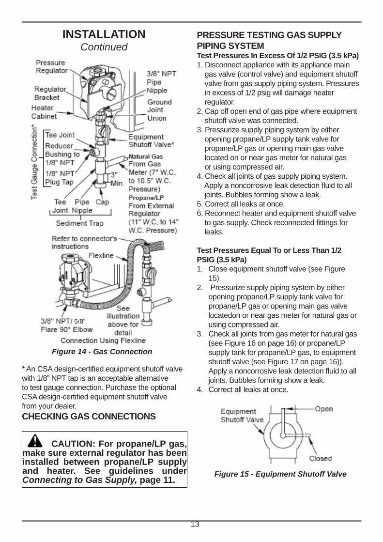
* An CSA design-certifi ed equipment shutoff valvewith 1/8” NPT tap is an acceptable alternativeto test gauge connection. Purchase the optionalCSA design-certifi ed equipment shutoff valvefrom your dealer. CHECKING GAS CONNECTIONS
Figure 14 - Gas Connection
PRESSURE TESTING GAS SUPPLYPIPING SYSTEMTest Pressures In Excess Of 1/2 PSIG (3.5 kPa)1. Disconnect appliance with its appliance main gas valve (control valve) and equipment shutoff valve from gas supply piping system. Pressures in excess of 1/2 psig will damage heater regulator.2. Cap off open end of gas pipe where equipment shutoff valve was connected.3. Pressurize supply piping system by either opening propane/LP supply tank valve for propane/LP gas or opening main gas valve located on or near gas meter for natural gas or using compressed air.4. Check all joints of gas supply piping system. Apply a noncorrosive leak detection fl uid to all joints. Bubbles forming show a leak.5. Correct all leaks at once.6. Reconnect heater and equipment shutoff valve to gas supply. Check reconnected fi ttings for leaks. Test Pressures Equal To or Less Than 1/2 PSIG (3.5 kPa)
Close equipment shutoff valve (see Figure 1. 15). Pressurize supply piping system by either 2. opening propane/LP supply tank valve for propane/LP gas or opening main gas valve locatedon or near gas meter for natural gas or using compressed air.Check all joints from gas meter for natural gas 3. (see Figure 16 on page 16) or propane/LP supply tank for propane/LP gas, to equipment shutoff valve (see Figure 17 on page 16)). Apply a noncorrosive leak detection fl uid to all joints. Bubbles forming show a leak.Correct all leaks at once.4.
INSTALLATIONContinued
13
Figure 15 - Equipment Shutoff Valve
CAUTION: For propane/LP gas, make sure external regulator has been installed between propane/LP supply and heater. See guidelines under Connecting to Gas Supply, page 11.
5/8"
14
CONNECTING TO ELECTRICAL SUPPLY (Only for Model IWH16 and IWH26)
INSTALLATIONContinued
CAUTION: Label all wires prior to disconnection when servicing controls. Wiring errors can cause improper and dangerous operation (see page 21).
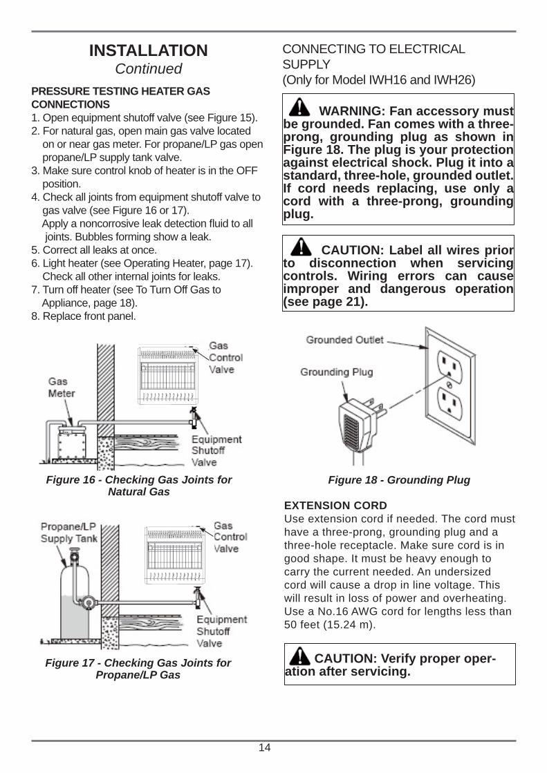
WARNING: Fan accessory must be grounded. Fan comes with a three-prong, grounding plug as shown in Figure 18. The plug is your protection against electrical shock. Plug it into a standard, three-hole, grounded outlet. If cord needs replacing, use only a cord with a three-prong, grounding plug.
EXTENSION CORDUse extension cord if needed. The cord musthave a three-prong, grounding plug and athree-hole receptacle. Make sure cord is ingood shape. It must be heavy enough to carry the current needed. An undersized cord will cause a drop in line voltage. This will result in loss of power and overheating. Use a No.16 AWG cord for lengths less than 50 feet (15.24 m).
CAUTION: Verify proper oper-ation after servicing.
Figure 18 - Grounding Plug
PRESSURE TESTING HEATER GASCONNECTIONS1. Open equipment shutoff valve (see Figure 15).2. For natural gas, open main gas valve located on or near gas meter. For propane/LP gas open propane/LP supply tank valve.3. Make sure control knob of heater is in the OFF position.4. Check all joints from equipment shutoff valve to gas valve (see Figure 16 or 17). Apply a noncorrosive leak detection fl uid to all joints. Bubbles forming show a leak.5. Correct all leaks at once.6. Light heater (see Operating Heater, page 17). Check all other internal joints for leaks.7. Turn off heater (see To Turn Off Gas to Appliance, page 18).8. Replace front panel.
Figure 16 - Checking Gas Joints for Natural Gas
Figure 17 - Checking Gas Joints forPropane/LP Gas
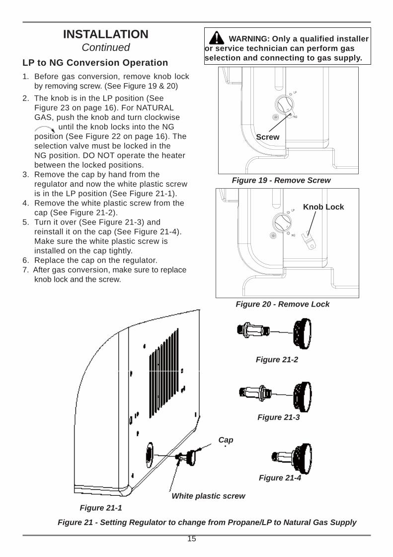
Figure 21 - Setting Regulator to change from Propane/LP to Natural Gas Supply
Figure 21-1
Figure 21-2
Figure 21-3
Figure 21-4
15
Cap
White plastic screw
1. Before gas conversion, remove knob lock by removing screw. (See Figure 19 & 20)
2. The knob is in the LP position (See Figure 23 on page 16). For NATURAL GAS, push the knob and turn clockwise until the knob locks into the NG position (See Figure 22 on page 16). The selection valve must be locked in the NG position. DO NOT operate the heater between the locked positions.
3. Remove the cap by hand from the regulator and now the white plastic screw is in the LP position (See Figure 21-1).
4. Remove the white plastic screw from the cap (See Figure 21-2).
5. Turn it over (See Figure 21-3) and reinstall it on the cap (See Figure 21-4). Make sure the white plastic screw is installed on the cap tightly.
6. Replace the cap on the regulator.7. After gas conversion, make sure to replace
knob lock and the screw.
INSTALLATIONContinued
LP to NG Conversion Operation
WARNING: Only a qualified installer or service technician can perform gas selection and connecting to gas supply.
Figure 19 - Remove Screw
Screw
Figure 20 - Remove Lock
Knob Lock
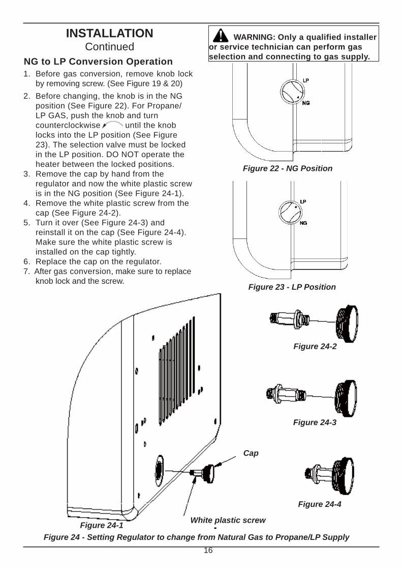
Figure 24-1
Figure 24-2
Figure 24-3
Figure 24-4
16Figure 24 - Setting Regulator to change from Natural Gas to Propane/LP Supply
Cap
White plastic screw
1. Before gas conversion, remove knob lock by removing screw. (See Figure 19 & 20)
2. Before changing, the knob is in the NG position (See Figure 22). For Propane/LP GAS, push the knob and turn counterclockwise until the knob locks into the LP position (See Figure 23). The selection valve must be locked in the LP position. DO NOT operate the heater between the locked positions.
3. Remove the cap by hand from the regulator and now the white plastic screw is in the NG position (See Figure 24-1).
4. Remove the white plastic screw from the cap (See Figure 24-2).
5. Turn it over (See Figure 24-3) and reinstall it on the cap (See Figure 24-4). Make sure the white plastic screw is installed on the cap tightly.
6. Replace the cap on the regulator.7. After gas conversion, make sure to replace
knob lock and the screw.
Figure 22 - NG Position
INSTALLATIONContinued
Figure 23 - LP Position
NG to LP Conversion Operation
WARNING: Only a qualified installer or service technician can perform gas selection and connecting to gas supply.
FOR YOUR SAFETY READ BEFORE LIGHTING
OPERATING HEATER
WARNING: If you do not follow these instructions exactly, a fi re or explosion may result causing property damage, personal injury or loss of life.
A. This appliance has a pilot which must be lit by hand. When lighting the pilot, follow these instructions exactly.B. BEFORE LIGHTING, smell all around the appliance area for gas. Be sure to smell next to the floor because some gas is heavier than air and will settle on the floor. WHAT TO DO IF YOU SMELL GAS • Do not try to light any appliance. • Do not touch any electric switch; do not use any phone in your building. • Immediately call your gas supplier from a neighbor’s phone. Follow the gas supplier’s instructions. • If you cannot reach your gas supplier, call the fire department.C. Use only your hand to push in or turn the gas control knob. Never use tools. If the knob will not push in or turn by hand, don’t try to repair it, call a qualified service technician. Force or attempted repair may result in a fire or explosion.D. Do not use this appliance if any part has been under water. Immediately call a qualified service technician to inspect the appliance and to replace any part of the control system and any gas control which has been under water.
LIGHTINGINSTRUCTIONS
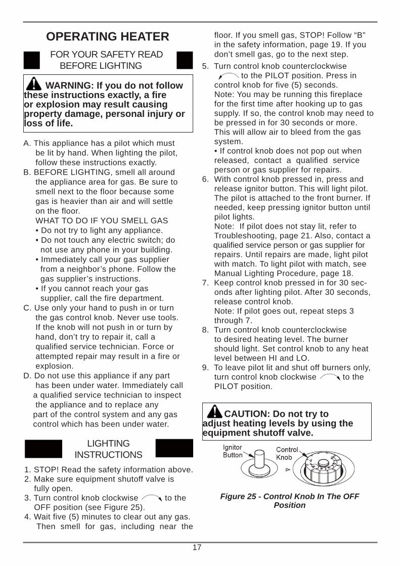
1. STOP! Read the safety information above.2. Make sure equipment shutoff valve is fully open.3. Turn control knob clockwise to the OFF position (see Figure 25).4. Wait five (5) minutes to clear out any gas. Then smell for gas, including near the
CAUTION: Do not try to adjust heating levels by using the equipment shutoff valve.
Figure 25 - Control Knob In The OFFPosition
5. Turn control knob counterclockwise to the PILOT position. Press in control knob for five (5) seconds. Note: You may be running this fireplace for the first time after hooking up to gas supply. If so, the control knob may need to be pressed in for 30 seconds or more. This will allow air to bleed from the gas system. • If control knob does not pop out when released, contact a qualified service person or gas supplier for repairs.6. With control knob pressed in, press and release ignitor button. This will light pilot. The pilot is attached to the front burner. If needed, keep pressing ignitor button until pilot lights. Note: If pilot does not stay lit, refer to Troubleshooting, page 21. Also, contact a qualifi ed service person or gas supplier for repairs. Until repairs are made, light pilot with match. To light pilot with match, see Manual Lighting Procedure, page 18.7. Keep control knob pressed in for 30 sec- onds after lighting pilot. After 30 seconds, release control knob. Note: If pilot goes out, repeat steps 3 through 7.8. Turn control knob counterclockwise to desired heating level. The burner should light. Set control knob to any heat level between HI and LO.9. To leave pilot lit and shut off burners only, turn control knob clockwise to the PILOT position.
floor. If you smell gas, STOP! Follow “B” in the safety information, page 19. If you don’t smell gas, go to the next step.
17
18
TO SELECTHEATING LEVEL
CAUTION: Do not try to adjust heating levels by using the equipment shutoff valve.
WARNING: When running heater, set control knob at locked positions. Never set control knob between locked positions. Poor combustion and higher levels of carbon monoxide may result.
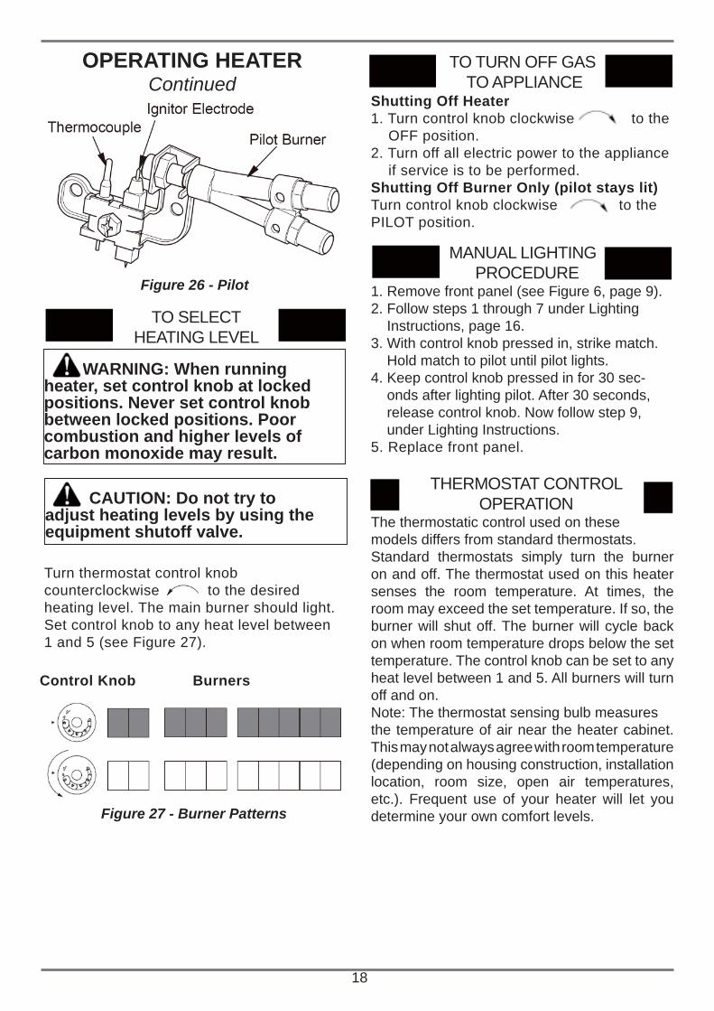
Figure 26 - Pilot
Turn thermostat control knob counterclockwise to the desired heating level. The main burner should light. Set control knob to any heat level between 1 and 5 (see Figure 27).
Control Knob Burners
TO TURN OFF GAS TO APPLIANCE
Shutting Off Heater1. Turn control knob clockwise to the OFF position.2. Turn off all electric power to the appliance if service is to be performed.Shutting Off Burner Only (pilot stays lit)Turn control knob clockwise to thePILOT position.
Figure 27 - Burner Patterns
OPERATING HEATERContinued
The thermostatic control used on thesemodels differs from standard thermostats.Standard thermostats simply turn the burner on and off. The thermostat used on this heater senses the room temperature. At times, the room may exceed the set temperature. If so, the burner will shut off. The burner will cycle back on when room temperature drops below the set temperature. The control knob can be set to any heat level between 1 and 5. All burners will turn off and on.Note: The thermostat sensing bulb measuresthe temperature of air near the heater cabinet. This may not always agree with room temperature (depending on housing construction, installation location, room size, open air temperatures, etc.). Frequent use of your heater will let you determine your own comfort levels.
THERMOSTAT CONTROL OPERATION
1. Remove front panel (see Figure 6, page 9).2. Follow steps 1 through 7 under Lighting Instructions, page 16.3. With control knob pressed in, strike match. Hold match to pilot until pilot lights.4. Keep control knob pressed in for 30 sec- onds after lighting pilot. After 30 seconds, release control knob. Now follow step 9, under Lighting Instructions.5. Replace front panel.
MANUAL LIGHTING PROCEDURE
INSPECTING HEATER
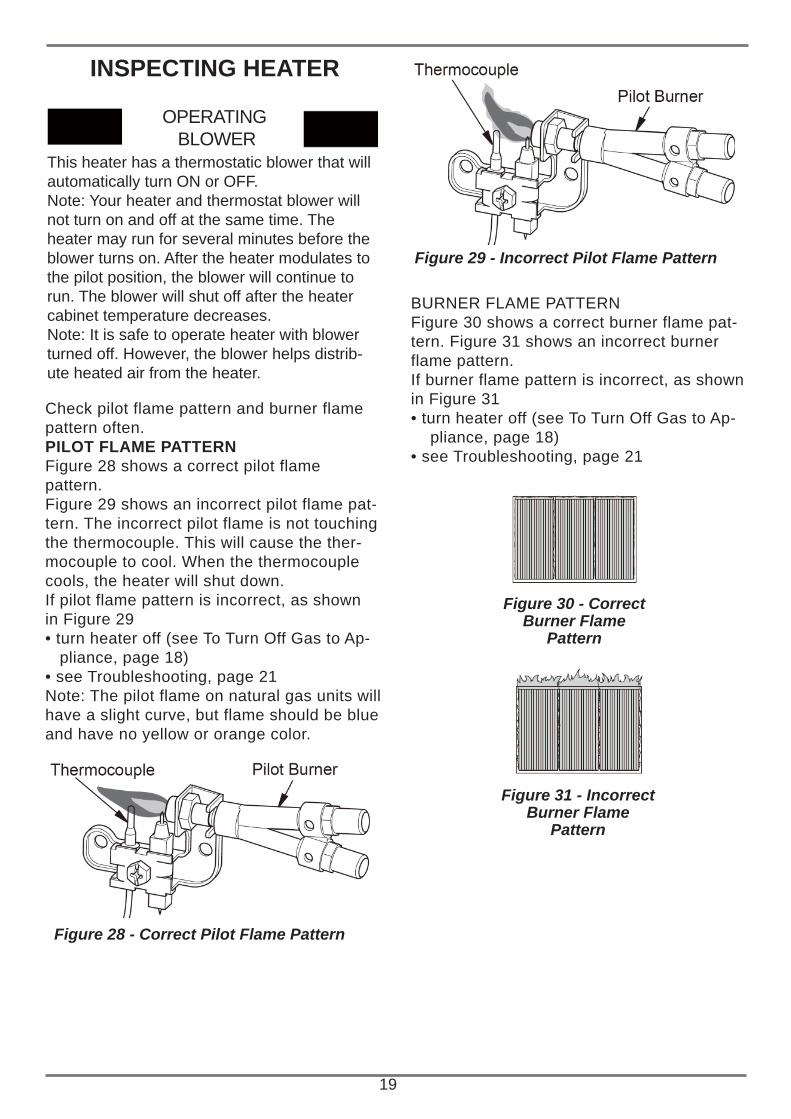
Check pilot flame pattern and burner flamepattern often.PILOT FLAME PATTERNFigure 28 shows a correct pilot flame pattern.Figure 29 shows an incorrect pilot flame pat-tern. The incorrect pilot flame is not touchingthe thermocouple. This will cause the ther-mocouple to cool. When the thermocouple cools, the heater will shut down.If pilot flame pattern is incorrect, as shownin Figure 29• turn heater off (see To Turn Off Gas to Ap- pliance, page 18)• see Troubleshooting, page 21Note: The pilot flame on natural gas units willhave a slight curve, but flame should be blueand have no yellow or orange color.
OPERATING BLOWER
This heater has a thermostatic blower that will automatically turn ON or OFF.Note: Your heater and thermostat blower willnot turn on and off at the same time. Theheater may run for several minutes before the blower turns on. After the heater modulates to the pilot position, the blower will continue to run. The blower will shut off after the heater cabinet temperature decreases.Note: It is safe to operate heater with blowerturned off. However, the blower helps distrib-ute heated air from the heater.
Figure 28 - Correct Pilot Flame Pattern
Figure 29 - Incorrect Pilot Flame Pattern
BURNER FLAME PATTERNFigure 30 shows a correct burner flame pat-tern. Figure 31 shows an incorrect burnerflame pattern.If burner flame pattern is incorrect, as shownin Figure 31• turn heater off (see To Turn Off Gas to Ap- pliance, page 18)• see Troubleshooting, page 21
19
Figure 30 - Correct Burner Flame
Pattern
Figure 31 - Incorrect Burner Flame
Pattern
CLEANING ANDMAINTENANCE
20
ODS/PILOT AND BURNERUse a vacuum cleaner, pressurized air orsmall, soft bristled brush to clean.
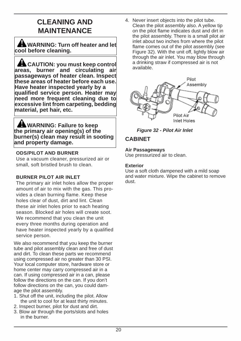
4. Never insert objects into the pilot tube. Clean the pilot assembly also. A yellow tip on the pilot fl ame indicates dust and dirt in the pilot assembly. There is a small pilot air inlet about two inches from where the pilot fl ame comes out of the pilot assembly (see Figure 32). With the unit off, lightly blow air through the air inlet. You may blow through a drinking straw if compressed air is not available.
CABINET
Air PassagewaysUse pressurized air to clean.
ExteriorUse a soft cloth dampened with a mild soapand water mixture. Wipe the cabinet to remove dust.
Figure 32 - Pilot Air Inlet WARNING: Failure to keep the primary air opening(s) of the burner(s) clean may result in sooting and property damage.
WARNING: Turn off heater and let cool before cleaning.
CAUTION: you must keep control areas, burner and circulating air passageways of heater clean. Inspect these areas of heater before each use. Have heater inspected yearly by aqualifi ed service person. Heater may need more frequent cleaning due to excessive lint from carpeting, bedding material, pet hair, etc.
BURNER PILOT AIR INLETThe primary air inlet holes allow the properamount of air to mix with the gas. This pro-vides a clean burning flame. Keep these holes clear of dust, dirt and lint. Clean these air inlet holes prior to each heating season. Blocked air holes will create soot. We recommend that you clean the unit every three months during operation and have heater inspected yearly by a qualified service person.
We also recommend that you keep the burnertube and pilot assembly clean and free of dustand dirt. To clean these parts we recommendusing compressed air no greater than 30 PSI.Your local computer store, hardware store orhome center may carry compressed air in acan. If using compressed air in a can, pleasefollow the directions on the can. If you don’tfollow directions on the can, you could dam-age the pilot assembly.1. Shut off the unit, including the pilot. Allow the unit to cool for at least thirty minutes.2. Inspect burner, pilot for dust and dirt.3. Blow air through the ports/slots and holes in the burner.
21
TROUBLESHOOTING
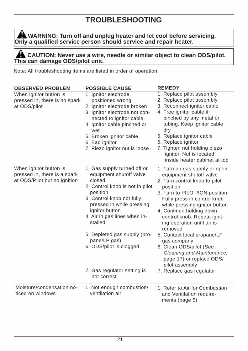
WARNING: Turn off and unplug heater and let cool before servicing.Only a qualifi ed service person should service and repair heater.
CAUTION: Never use a wire, needle or similar object to clean ODS/pilot. This can damage ODS/pilot unit.Note: All troubleshooting items are listed in order of operation.
OBSERVED PROBLEMWhen ignitor button ispressed in, there is no sparkat ODS/pilot
POSSIBLE CAUSE1. Ignitor electrode positioned wrong2. Ignitor electrode broken3. Ignitor electrode not con- nected to ignitor cable4. Ignitor cable pinched or wet5. Broken ignitor cable6. Bad ignitor7. Piezo ignitor nut is loose
REMEDY1. Replace pilot assembly2. Replace pilot assembly3. Reconnect ignitor cable4. Free ignitor cable if pinched by any metal or tubing. Keep ignitor cable dry5. Replace ignitor cable6. Replace ignitor7. Tighten nut holding piezo ignitor. Nut is located inside heater cabinet at top
1. Turn on gas supply or open equipment shutoff valve2. Turn control knob to pilot position3. Turn to PILOT/IGN position. Fully press in control knob while pressing ignitor button4. Continue holding down control knob. Repeat ignit- ing operation until air is removed5. Contact local propane/LP gas company6. Clean ODS/pilot (See Cleaning and Maintenance, page 17) or replace ODS/ pilot assembly7. Replace gas regulator
When ignitor button ispressed in, there is a sparkat ODS/Pilot but no ignition
1. Gas supply turned off or equipment shutoff valve closed2. Control knob is not in pilot position3. Control knob not fully pressed in while pressing ignitor button4. Air in gas lines when in- stalled
5. Depleted gas supply (pro- pane/LP gas)6. ODS/pilot is clogged
7. Gas regulator setting is not correct
1. Refer to Air for Combustion and Ventilation require- ments (page 5)
Moisture/condensation no-ticed on windows
1. Not enough combustion/ ventilation air
22
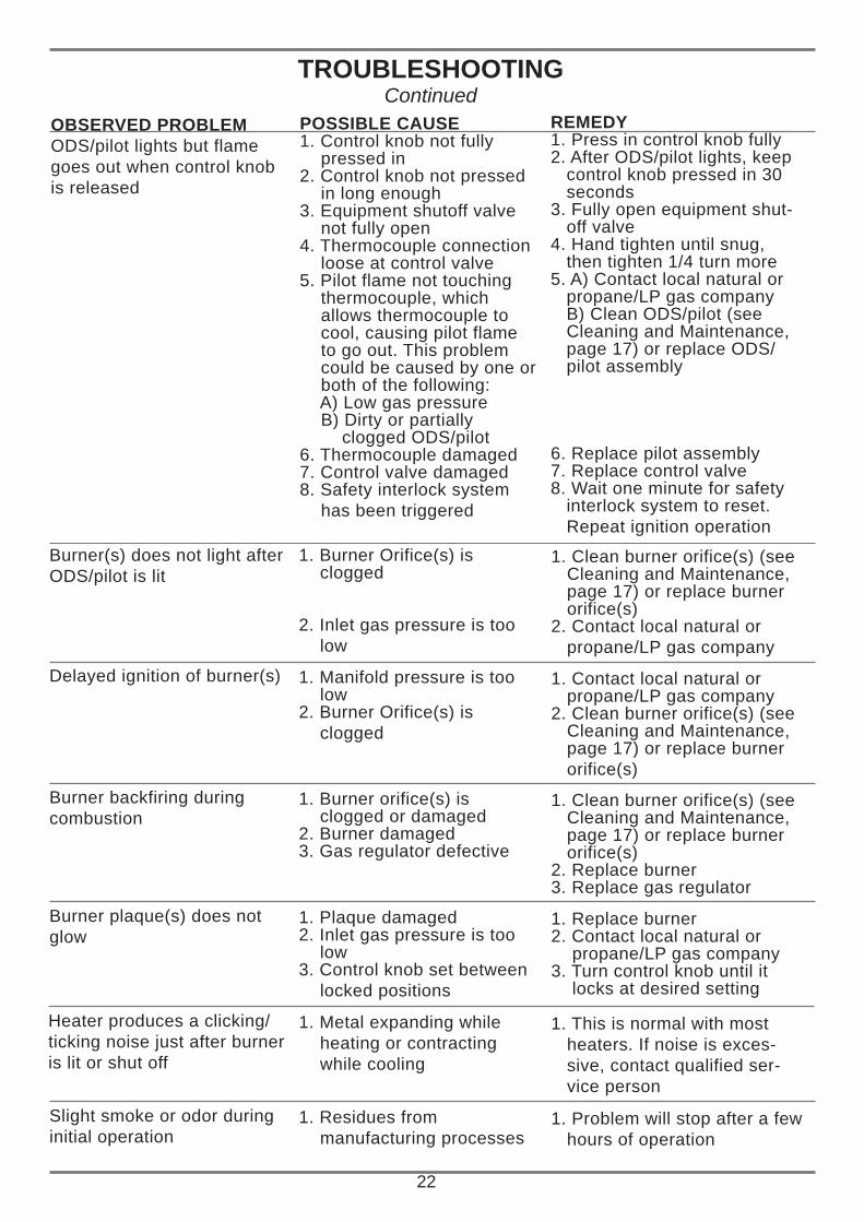
TROUBLESHOOTINGContinued
OBSERVED PROBLEMODS/pilot lights but flamegoes out when control knobis released
POSSIBLE CAUSE1. Control knob not fully pressed in2. Control knob not pressed in long enough3. Equipment shutoff valve not fully open4. Thermocouple connection loose at control valve5. Pilot flame not touching thermocouple, which allows thermocouple to cool, causing pilot flame to go out. This problem could be caused by one or both of the following: A) Low gas pressure B) Dirty or partially clogged ODS/pilot6. Thermocouple damaged7. Control valve damaged8. Safety interlock system has been triggered
REMEDY1. Press in control knob fully2. After ODS/pilot lights, keep control knob pressed in 30 seconds3. Fully open equipment shut- off valve4. Hand tighten until snug, then tighten 1/4 turn more5. A) Contact local natural or propane/LP gas company B) Clean ODS/pilot (see Cleaning and Maintenance, page 17) or replace ODS/ pilot assembly
6. Replace pilot assembly7. Replace control valve8. Wait one minute for safety interlock system to reset. Repeat ignition operation
1. Clean burner orifice(s) (see Cleaning and Maintenance, page 17) or replace burner orifice(s)2. Contact local natural or propane/LP gas company
Burner(s) does not light afterODS/pilot is lit
1. Burner Orifice(s) is clogged
2. Inlet gas pressure is too low
1. Contact local natural or propane/LP gas company2. Clean burner orifice(s) (see Cleaning and Maintenance, page 17) or replace burner orifice(s)
Delayed ignition of burner(s) 1. Manifold pressure is too low2. Burner Orifice(s) is clogged
1. Clean burner orifice(s) (see Cleaning and Maintenance, page 17) or replace burner orifice(s)2. Replace burner3. Replace gas regulator
Burner backfiring duringcombustion
1. Burner orifice(s) is clogged or damaged2. Burner damaged3. Gas regulator defective
1. Replace burner2. Contact local natural or propane/LP gas company3. Turn control knob until it locks at desired setting
Burner plaque(s) does notglow
1. Plaque damaged2. Inlet gas pressure is too low3. Control knob set between locked positions
1. This is normal with most heaters. If noise is exces- sive, contact qualified ser- vice person
Heater produces a clicking/ticking noise just after burneris lit or shut off
1. Metal expanding while heating or contracting while cooling
1. Problem will stop after a few hours of operation
Slight smoke or odor duringinitial operation
1. Residues from manufacturing processes
23
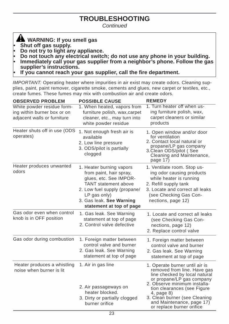
WARNING: If you smell gasShut off gas supply.• Do not try to light any appliance.• Do not touch any electrical switch; do not use any phone in your building.• Immediately call your gas supplier from a neighbor’s phone. Follow the gas • supplier’s instructions.If you cannot reach your gas supplier, call the fi re department.•
IMPORTANT: Operating heater where impurities in air exist may create odors. Cleaning sup-plies, paint, paint remover, cigarette smoke, cements and glues, new carpet or textiles, etc.,create fumes. These fumes may mix with combustion air and create odors.OBSERVED PROBLEMWhite powder residue form-ing within burner box or onadjacent walls or furniture
POSSIBLE CAUSE1. When heated, vapors from furniture polish, wax,carpet cleaner, etc., may turn into white powder residue
REMEDY1. Turn heater off when us- ing furniture polish, wax, carpet cleaners or similar products
Heater shuts off in use (ODS operates)
1. Heater burning vapors from paint, hair spray, glues, etc. See IMPOR- TANT statement above2. Low fuel supply (propane/ LP gas only)3. Gas leak. See Warning statement at top of page
1. Operate burner until air is removed from line. Have gas line checked by local natural or propane/LP gas company2. Observe minimum installa- tion clearances (see Figure 4, page 8)3. Clean burner (see Cleaning and Maintenance, page 17) or replace burner orifice
Heater produces a whistlingnoise when burner is lit
1. Air in gas line
2. Air passageways on heater blocked.3. Dirty or partially clogged burner orifice
TROUBLESHOOTINGContinued
1. Open window and/or door for ventilation2. Contact local natural or propane/LP gas company3.Clean ODS/pilot ( See Cleaning and Maintenance, page 17)
Heater produces unwantedodors
1. Not enough fresh air is available2. Low line pressure3. ODS/pilot is partially clogged
1. Ventilate room. Stop us- ing odor causing products while heater is running2. Refill supply tank3. Locate and correct all leaks (see Checking Gas Con- nections, page 12)
1. Locate and correct all leaks (see Checking Gas Con- nections, page 12)2. Replace control valve
Gas odor even when controlknob is in OFF position
1. Gas leak. See Warning statement at top of page2. Control valve defective
1. Foreign matter between control valve and burner2. Gas leak. See Warning statement at top of page
1. Foreign matter between control valve and burner2. Gas leak. See Warning statement at top of page
Gas odor during combustion
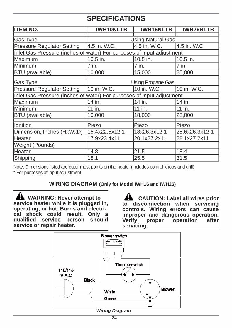
ITEM NO. IWH10NLTB IWH16NLTB IWH26NLTB
Gas Type Using Natural GasPressure Regulator Setting 4.5 in. W.C. 4.5 in. W.C. 4.5 in. W.C.Inlet Gas Pressure (inches of water) For purposes of input adjustmentMaximum 10.5 in. 10.5 in. 10.5 in.Minimum 7 in. 7 in. 7 in.BTU (available) 10,000 15,000 25,000
Gas Type Using Propane GasPressure Regulator Setting 10 in. W.C. 10 in. W.C. 10 in. W.C.Inlet Gas Pressure (inches of water) For purposes of input adjustmentMaximum 14 in. 14 in. 14 in.Minimum 11 in. 11 in. 11 in.BTU (available) 10,000 18,000 28,000
Ignition Piezo Piezo PiezoDimension, Inches (HxWxD) 15.4x22.5x12.1 18x26.3x12.1 25.6x26.3x12.1Heater 17.9x23.4x11 20.1x27.2x11 28.1x27.2x11Weight (Pounds)Heater 14.8 21.5 18.4Shipping 18.1 25.5 31.5
SPECIFICATIONS
24
Note: Dimensions listed are outer most points on the heater (includes control knobs and grill)* For purposes of input adjustment.
WIRING DIAGRAM (Only for Model IWH16 and IWH26)
WARNING: Never attempt toservice heater while it is plugged in, operating, or hot. Burns and electri-cal shock could result. Only a qualifi ed service person should service or repair heater.
CAUTION: Label all wires prior to disconnection when servicing controls. Wiring errors can cause improper and dangerous operation. Verify proper operation after servicing.
Wiring Diagram
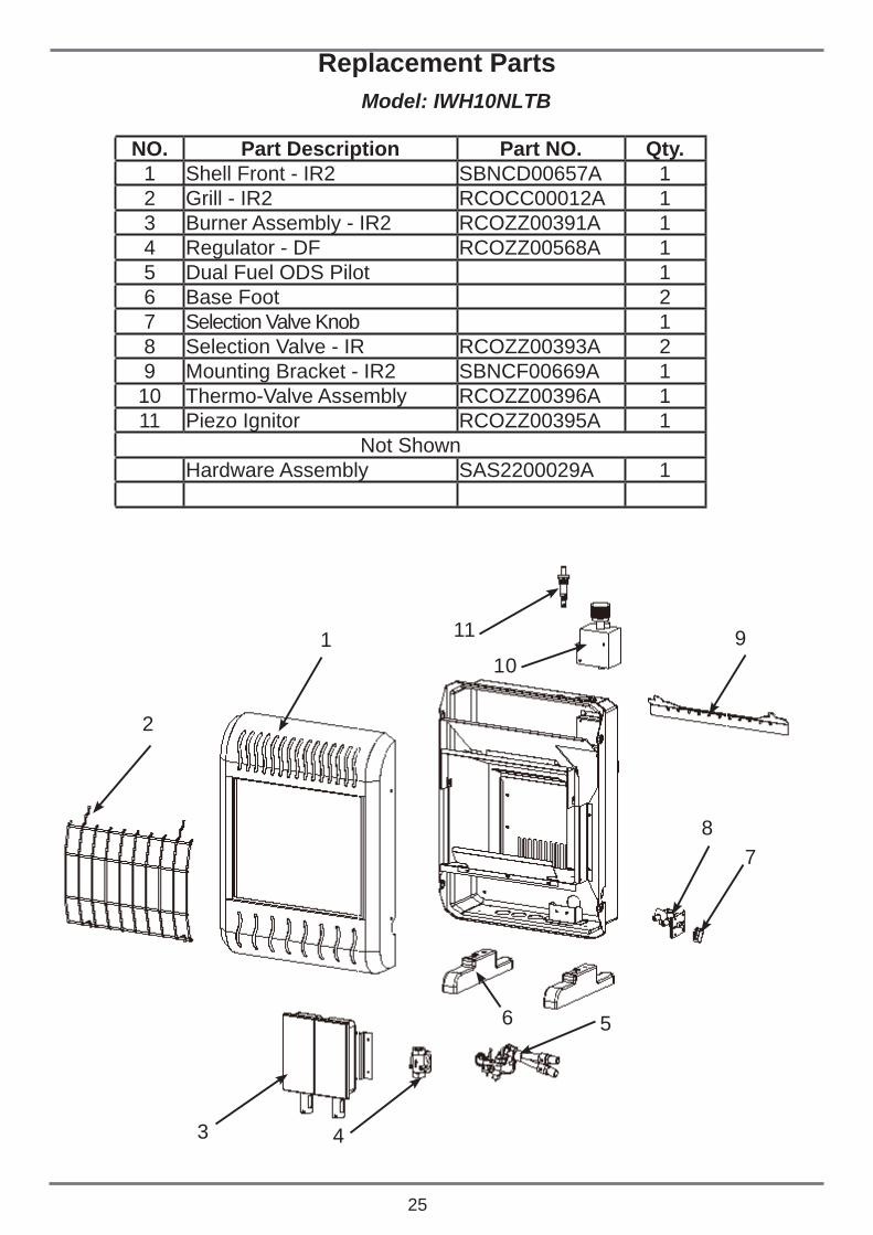
Replacement PartsModel: IWH10NLTB
NO. Part Description Part NO. Qty.1 Shell Front - IR2 SBNCD00657A 12 Grill - IR2 RCOCC00012A 13 Burner Assembly - IR2 RCOZZ00391A 14 Regulator - DF RCOZZ00568A 15 Dual Fuel ODS Pilot 16 Base Foot 27 Selection Valve Knob 18 Selection Valve - IR RCOZZ00393A 29 Mounting Bracket - IR2 SBNCF00669A 1
10 Thermo-Valve Assembly RCOZZ00396A 111 Piezo Ignitor RCOZZ00395A 1
Not ShownHardware Assembly SAS2200029A 1
25
10
3
2
1
4
56
78
11 9
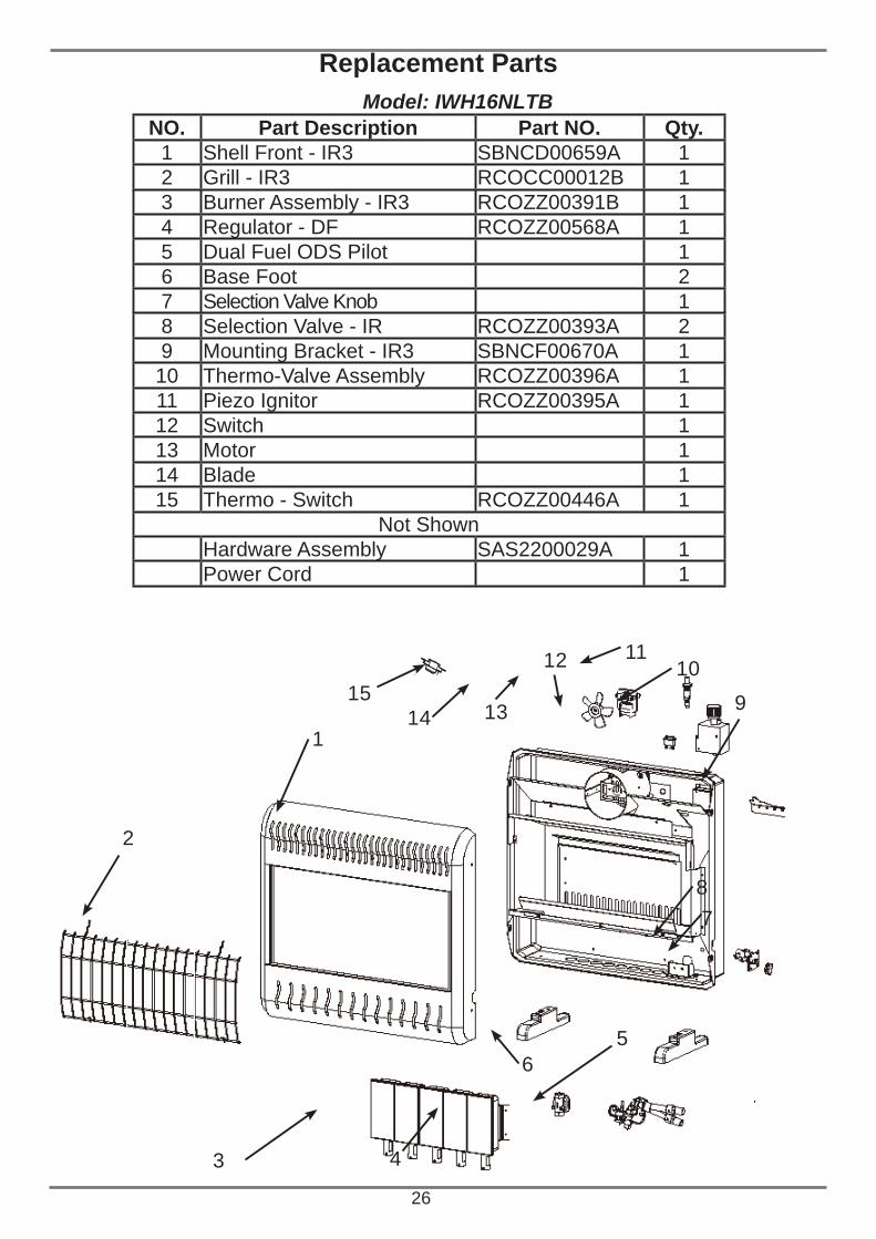
Replacement PartsModel: IWH16NLTB
26
11
3
2
1
4
56
78
109
12
131415
NO. Part Description Part NO. Qty.1 Shell Front - IR3 SBNCD00659A 12 Grill - IR3 RCOCC00012B 13 Burner Assembly - IR3 RCOZZ00391B 14 Regulator - DF RCOZZ00568A 15 Dual Fuel ODS Pilot 16 Base Foot 27 Selection Valve Knob 18 Selection Valve - IR RCOZZ00393A 29 Mounting Bracket - IR3 SBNCF00670A 1
10 Thermo-Valve Assembly RCOZZ00396A 111 Piezo Ignitor RCOZZ00395A 112 Switch 113 Motor 114 Blade 115 Thermo - Switch RCOZZ00446A 1
Not ShownHardware Assembly SAS2200029A 1Power Cord 1
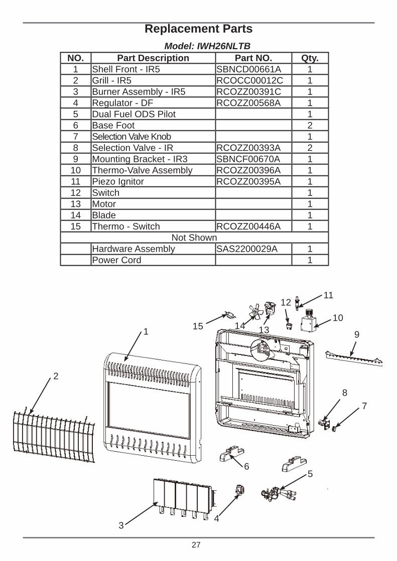
Replacement PartsModel: IWH26NLTB
27
10
3
2
1
4
56
78
11
9
12
131415
NO. Part Description Part NO. Qty.1 Shell Front - IR5 SBNCD00661A 12 Grill - IR5 RCOCC00012C 13 Burner Assembly - IR5 RCOZZ00391C 14 Regulator - DF RCOZZ00568A 15 Dual Fuel ODS Pilot 16 Base Foot 27 Selection Valve Knob 18 Selection Valve - IR RCOZZ00393A 29 Mounting Bracket - IR3 SBNCF00670A 1
10 Thermo-Valve Assembly RCOZZ00396A 111 Piezo Ignitor RCOZZ00395A 112 Switch 113 Motor 114 Blade 115 Thermo - Switch RCOZZ00446A 1
Not ShownHardware Assembly SAS2200029A 1Power Cord 1
REPLACEMENT PARTSNote: Use only original replacement parts.This will protect your warranty coverage forparts replaced under warranty.
28
PARTS UNDER WARRANTYContact authorized dealers of this product.If they can’t supply original replacement part(s), call Sure Heat Products’ Technical Service Department at (800) 229-5647.When calling Sure Heat have ready• your name• your address• model and serial numbers of your heater• how heater was malfunctioning• type of gas used (propane/LP or natural gas)• purchase dateUsually, we will ask you to return the part to the factory.
PARTS NOT UNDER WARRANTYContact authorized dealers of this product.If they can’t supply original replacementpart(s), either contact your nearest PartsCentral or call Sure Heat Heating Products at (800) 229-5647 for referral information.When calling Sure Heat, have ready• model number of your heater• the replacement part number
SERVICE HINTSWhen Gas Pressure Is Too Low• pilot will not stay lit• burner will have delayed ignition• heater will not produce specified heat• propane/LP gas supply may be lowYou may feel your gas pressure is too low. Ifso, contact your local natural or propane/LPgas supplier.Note: Use only original replacement parts.This will protect your warranty coverage forparts replaced under warranty.
TECHNICAL SERVICEYou may have further questions about instal-lation, operation or troubleshooting. If so,contact Sure Heat Heating Products’ Technical Service Department at (800) 229-5647. When calling please have your model and serial numbers of your heater ready.You can also visit Sure Heat Heating Products’ technical service web site at www.sureheat.com.
LIMITED WARRANTYSure Heat Mfg. warrants that the components of this appliance are warranted free from defects in material and workmanship for two (2) years from the date of purchase. Sure Heat Mfg. at its option, will repair or replace this product or any component of the product found to be defective during the warranty period. Replacement will be made with a new manufactured product or component. If the product is no longer available, replacement may be made with a similar product of equal value. This warranty does not include transportation or shipping costs of any kind. This is your exclusive warranty.
This warranty is valid for the original retail purchaser from the date of initial retail purchase and is not transferable. Keep the original sales receipt. Proof of purchase is required to obtain warranty parts.
This warranty does not cover normal wear of parts such as scratches and dents of the components or damage resulting from any of the following:
negligent use or misuse of the product, including exposing the product to chemicals or cleaning products not • approved by Sure Heat Mfg.
corrosion, rust or discoloring of any kind• use or installation contrary to specifi ed instructions and applicable building codes, including heating the product • to temperatures above its rated specifi cations which can cause considerable warping
disassembly, including removal of the product from a built-in installation• damage resulting from accident, alteration, misuse, abuse, hostile environments, or improper installation• repair or alteration• acts of God, such as fi re, fl ood hurricanes and tornadoes• gas cylinders, propane tanks or other fuel delivery systems, including connections to a household fuel supply• usage other than single-family household use such as commercial or industrial use• minor warping or discoloration of parts, which is normal and not a defect under this warranty•
DO NOT RETURN THIS PRODUCT TO THE PLACE OF PURCHASE
If the appliance does not operate properly, fi rst thoroughly carry out the instructions provided with the unit to ensure that the appliance is installed correctly and check the troubleshooting section in the use and care manual.
We recommend you return the warranty registration card so that you can be contacted with any questions of safety arise that could affect you. The return of the warranty registration card is not a condition for warranty coverage.
Because of continuing product improvement, these specifi cations are subject to change without notice.
If you have other questions or need replacement parts contact our
Customer Service Hotline at (800) 229-5647 or
visit our website at www.sureheat.com
Sure Heat Manufacturing, 1861 West Oak Parkway Marietta, GA 30062