Embed Size (px)
Citation preview
UNVENTED (VENT-FREE) GASSTOVE HEATEROWNER’S OPERATION AND INSTALLATION MANUAL
For more information, visit www.desatech.comFor more information, visit www.desatech.com
Save this manual for future reference.Save this manual for future reference.
Model SVYD18NR/PR Series Remote-Ready Control Gas Log Heater(Burner System For Cast Iron Stoves)
WARNING: If the information in thismanual is not followed exactly, a fire orexplosion may result causing propertydamage, personal injury, or loss of life.
— Do not store or use gasoline or otherflammable vapors and liquids in thevicinity of this or any other appliance.
— WHAT TO DO IF YOU SMELL GAS• Do not try to light any appliance.• Do not touch any electrical switch;
do not use any phone in yourbuilding.
• Immediately call your gas supplierfrom a neighbor’s phone. Follow thegas supplier’s instructions.
• If you cannot reach your gas sup-plier, call the fire department.
— Installation and service must be per-formed by a qualified installer, serviceagency, or the gas supplier.
WARNING: Improper installation, adjustment,alteration, service, or maintenance can causeinjury or property damage. Refer to this manualfor correct installation and operational proce-dures. For assistance or additional informationconsult a qualified installer, service agency, orthe gas supplier.
WARNING: This is an unvented gas-fired heater.It uses air (oxygen) from the room in which it isinstalled. Provisions for adequate combustionand ventilation air must be provided. Refer toAir for Combustion and Ventilation section onpage 4 of this manual.
WARNING: The SVYD18NR/PR series vent-free gas log heater is only approved for use inthe SCIVF(*) series, PSCIVF(*) series, or VH(*)series cast iron stove models.
(* Indicates Color Suffix Designation)
This appliance may be installed in an aftermarket*, permanently located, manufactured(mobile) home, where not prohibited by local codes.This appliance is only for use with the type of gas indicated on the rating plate. This appli-ance is not convertible for use with other gases.
* Aftermarket: Completion of sale, not for purpose of resale, from the manufacturer
Amity™ Victor Hearth™
Patent Pending
111162-01B
2
For more information, visit www.desatech.comFor more information, visit www.desatech.com
TABLE OF CONTENTSSAFETY INFORMATION
SAFETY INFORMATION WARNINGS
WARNING: This product contains and/or generateschemicals known to the State of California to causecancer or birth defects, or other reproductive harm.
DANGER: Carbon monoxide poisoning may leadto death!
Carbon Monoxide Poisoning: Early signs of carbon monoxidepoisoning resemble the flu, with headaches, dizziness, or nausea.If you have these signs, the heater may not be working properly.Get fresh air at once! Have heater serviced. Some people aremore affected by carbon monoxide than others. These includepregnant women, people with heart or lung disease or anemia,those under the influence of alcohol, and those at high altitudes.
Natural and Propane/LP Gas: Natural and propane/LP gases areodorless. An odor-making agent is added to the gas. The odorhelps you detect a gas leak. However, the odor added to the gas canfade. Gas may be present even though no odor exists.
Make certain you read and understand all warnings. Keep this manualfor reference. It is your guide to safe and proper operation of this heater.
IMPORTANT: Read this owner’s manual carefully andcompletely before trying to assemble, operate, or ser-vice this heater. Improper use of this heater can causeserious injury or death from burns, fire, explosion,electrical shock, and carbon monoxide poisoning.
WARNING: Any change to this heater or its controlscan be dangerous.
WARNING: Do not allow fans to blow directly intothe fireplace. Avoid any drafts that alter burner flamepatterns. Ceiling fans can create drafts that alterburner flame patterns. Altered burner patterns cancause sooting.
WARNING: Do not use a blower insert, heatexchanger insert, or other accessory not approvedfor use with this fireplace.
Due to high temperatures, the appliance should belocated out of traffic and away from furniture anddraperies.
Do not place clothing or other flammable materialon or near the appliance. Never place any objectson the heater.
Stove becomes very hot when running heater. Keepchildren and adults away from hot surface to avoid burnsor clothing ignition. Heater will remain hot for a time aftershutdown. Allow surface to cool before touching.
Carefully supervise young children when they are inthe room with stove. When using the optional hand-held remote accessory, keep selector switch in theOFF position to prevent children from turning onburners with remote.
Keep the appliance area clear and free from combus-tible materials, gasoline, and other flammable vaporsand liquids.
TABLE OF CONTENTSSAFETY INFORMATION ............................................................ 2
PRODUCT IDENTIFICATION ..................................................... 3
LOCAL CODES ........................................................................... 3
PRODUCT FEATURES .............................................................. 4
AIR FOR COMBUSTION AND VENTILATION ........................... 4
INSTALLATION ........................................................................... 6
OPERATING HEATER .............................................................. 13
INSPECTING BURNERS.......................................................... 16
CLEANING AND MAINTENANCE ............................................ 16
TROUBLESHOOTING .............................................................. 18
SPECIFICATIONS .................................................................... 21
WIRING DIAGRAM ................................................................... 21
REPLACEMENT PARTS .......................................................... 21
SERVICE HINTS....................................................................... 21
TECHNICAL SERVICE ............................................................. 21
ILLUSTRATED PARTS BREAKDOWN AND PARTS LIST ....... 22
ACCESSORIES ........................................................................ 26
OWNER’S REGISTRATION FORM .......................................... 27
WARRANTY INFORMATION ...................................... Back Cover
111162-01B
33
For more information, visit www.desatech.comFor more information, visit www.desatech.com
ON
OFF
REMOTE
PILOT
OFF
ONLO
HI
SAFETY INFORMATIONPRODUCT IDENTIFICATION
LOCAL CODES
1. This appliance is only for use with the type of gas indicated onthe rating plate. This appliance is not convertible for use withother gases.
2. Do not place propane/LP supply tank(s) inside any structure. Lo-cate propane/LP supply tank(s) outdoors (propane/LP units only).
3. If you smell gas• shut off gas supply• do not try to light any appliance• do not touch any electrical switch; do not use any phone in
your building• immediately call your gas supplier from a neighbor’s phone.
Follow the gas supplier’s instructions• if you cannot reach your gas supplier, call the fire department
4. This heater shall not be installed in a bedroom or bathroom.
5. Do not use this stove as a wood burning fireplace. Use only modelSVYD18PR/NR series vent-free gas log heater for SCIVF(*),PSCIVF(*), and VH(*) series cast iron stove models.
6. Do not add extra logs or ornaments such as pine cones, vermicu-lite, or rock wool. Using these added items can cause sooting.
7. This log heater is designed to be smokeless. If logs ever appearto smoke, turn off heater and call a qualified service person.Note: During initial operation, slight smoking could occur dueto log curing and heater burning manufacturing residues.
8. To prevent the creation of soot, follow the instructions in Clean-ing and Maintenance, page 16.
9. Before using furniture polish, wax, carpet cleaners, or similarproducts, turn heater off. If heated, the vapors from these prod-ucts may create a white powder residue within burner box oron adjacent walls or furniture.
10. This heater needs fresh, outside air ventilation to run properly.This heater has an Oxygen Depletion Sensing (ODS) safetyshutoff system. The ODS shuts down the heater if not enoughfresh air is available. See Air for Combustion and Ventilation,pages 4 through 6. If heater keeps shutting off, see Trouble-shooting, pages 18 through 20.
11. Do not run heater• where flammable liquids or vapors are used or stored• under dusty conditions
12. Do not use this stove to cook food or burn paper or other objects.
13. Do not use heater if any part has been exposed to or underwater. Immediately call a qualified service technician to in-spect the room heater and to replace any part of the controlsystem and any gas control which has been under water.
14. Do not operate heater if any log is broken. Do not operateheater if a log is chipped (dime-sized or larger).
15. Turn heater off and let cool before servicing. Only a qualifiedservice person should service and repair heater.
SAFETY INFORMATIONContinued
16. Operating heater above elevations of 4,500 feet could causepilot outage.
17. To prevent performance problems, the use of a propane/LPtank of less than 100 lb. capacity (propane/LP units only).
18. Provide adequate clearances around air openings.
PRODUCT IDENTIFICATION
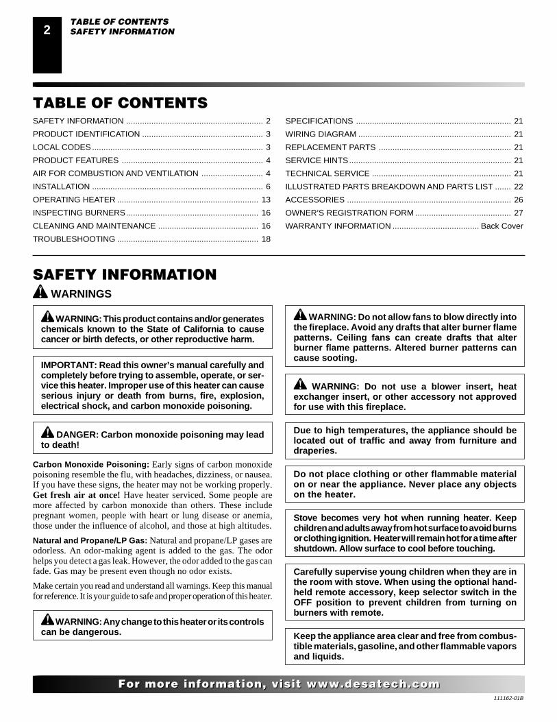
Figure 1 - Typical Stove Cabinet Model with Gas Log Heater(Shown is Amity™ Model with Model SVYD18PR/NR Heater)
StoveBody
Stove Door(Shown in theopen position)
Piezo IgnitorControlKnob
One PieceLog SetInside StoveCavity
Gas Log HeaterBase Assembly
Flame AdjustmentKnob
RemoteSelectorSwitch
LOCAL CODESInstall and use heater with care. Follow all local codes. In theabsence of local codes, use the latest edition of The National FuelGas Code ANSI Z223.1/NFPA 54*.
*Available from:
American National Standards Institute, Inc.1430 Broadway
New York, NY 10018
National Fire Protection Association, Inc.Batterymarch Park
Quincy, MA 02269

111162-01B
4
For more information, visit www.desatech.comFor more information, visit www.desatech.com
PRODUCT FEATURESOPERATIONThis heater is clean burning. It requires no outside venting. There isno heat loss out a vent or up a chimney. Heat is generated by realistic,dancing yellow flames. This heater is designed for vent-free opera-tion. State and local codes in some areas prohibit the use of vent-freeheaters.
SAFETY PILOTThis heater has a pilot with an Oxygen Depletion Sensing (ODS)safety shutoff system. The ODS/pilot is a required feature for vent-free room heaters. The ODS/pilot shuts off the heater if there is notenough fresh air.
PIEZO IGNITION SYSTEMThis heater has a piezo ignitor. This system requires no matches,batteries, or other sources to light heater.
AIR FOR COMBUSTION ANDVENTILATION
Today’s homes are built more energy efficient than ever. Newmaterials, increased insulation, and new construction methods helpreduce heat loss in homes. Home owners weather strip and caulkaround windows and doors to keep the cold air out and the warm airin. During heating months, home owners want their homes asairtight as possible.
While it is good to make your home energy efficient, your homeneeds to breathe. Fresh air must enter your home. All fuel-burningappliances need fresh air for proper combustion and ventilation.
Exhaust fans, fireplaces, clothes dryers, and fuel burning appliancesdraw air from the house to operate. You must provide adequate freshair for these appliances. This will insure proper venting of ventedfuel-burning appliances.
PROVIDING ADEQUATE VENTILATIONThe following are excerpts from National Fuel Gas Code,ANSI Z223.1/ NFPA 54, Section 5.3, Air for Combustion andVentilation.
All spaces in homes fall into one of the three following ventilationclassifications:
1. Unusually Tight Construction
2. Unconfined Space
3. Confined Space
The information on pages 4 through 6 will help you classify yourspace and provide adequate ventilation.
Unusually Tight Construction
The air that leaks around doors and windows may provide enoughfresh air for combustion and ventilation. However, in buildings ofunusually tight construction, you must provide additional fresh air.
Unusually tight construction is defined as constructionwhere:a. walls and ceilings exposed to the outside atmosphere
have a continuous water vapor retarder with a ratingof one perm (6 x 10-11 kg per pa-sec-m2) or less withopenings gasketed or sealed and
b. weather stripping has been added on openable win-dows and doors and
c. caulking or sealants are applied to areas such asjoints around window and door frames, between soleplates and floors, between wall-ceiling joints, betweenwall panels, at penetrations for plumbing, electrical,and gas lines, and at other openings.
If your home meets all of the three criteria above, youmust provide additional fresh air. See Ventilation AirFrom Outdoors, page 6.
If your home does not meet all of the three criteria above,proceed to Determining Fresh-Air Flow For Heater Loca-tion, page 5.
Confined and Unconfined Space
The National Fuel Gas Code, ANSI Z223.1/NFPA 54 defines aconfined space as a space whose volume is less than 50 cubic feetper 1,000 Btu per hour (4.8 m3 per kw) of the aggregate input ratingof all appliances installed in that space and an unconfined space asa space whose volume is not less than 50 cubic feet per 1,000 Btu perhour (4.8 m3 per kw) of the aggregate input rating of all appliancesinstalled in that space. Rooms communicating directly with thespace in which the appliances are installed*, through openings notfurnished with doors, are considered a part of the unconfined space.
* Adjoining rooms are communicating only if there are doorlesspassageways or ventilation grills between them.
WARNING: This heater shall not be installed ina confined space or unusually tight constructionunless provisions are provided for adequate com-bustion and ventilation air. Read the following in-structions to insure proper fresh air for this andother fuel-burning appliances in your home.
PRODUCT FEATURESAIR FOR COMBUSTION AND VENTILATION
Providing Adequate Ventilation
111162-01B
55
For more information, visit www.desatech.comFor more information, visit www.desatech.com
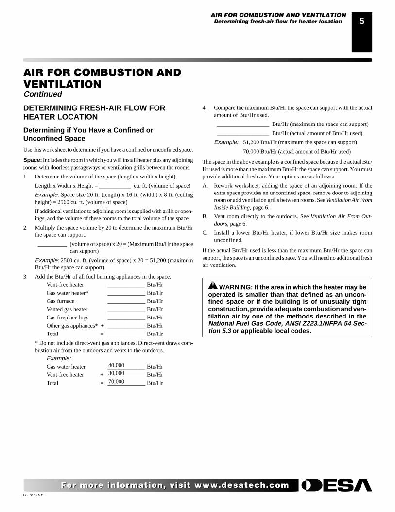
DETERMINING FRESH-AIR FLOW FORHEATER LOCATION
Determining if You Have a Confined orUnconfined Space
Use this work sheet to determine if you have a confined or unconfined space.
Space: Includes the room in which you will install heater plus any adjoiningrooms with doorless passageways or ventilation grills between the rooms.
1. Determine the volume of the space (length x width x height).
Length x Width x Height = ___________ cu. ft. (volume of space)
Example: Space size 20 ft. (length) x 16 ft. (width) x 8 ft. (ceilingheight) = 2560 cu. ft. (volume of space)
If additional ventilation to adjoining room is supplied with grills or open-ings, add the volume of these rooms to the total volume of the space.
2. Multiply the space volume by 20 to determine the maximum Btu/Hrthe space can support.
__________ (volume of space) x 20 = (Maximum Btu/Hr the spacecan support)
Example: 2560 cu. ft. (volume of space) x 20 = 51,200 (maximumBtu/Hr the space can support)
3. Add the Btu/Hr of all fuel burning appliances in the space.
Vent-free heater _____________ Btu/Hr
Gas water heater* _____________ Btu/Hr
Gas furnace _____________ Btu/Hr
Vented gas heater _____________ Btu/Hr
Gas fireplace logs _____________ Btu/Hr
Other gas appliances* + _____________ Btu/Hr
Total = _____________ Btu/Hr
* Do not include direct-vent gas appliances. Direct-vent draws com-bustion air from the outdoors and vents to the outdoors.
Example:Gas water heater _____________ Btu/Hr
Vent-free heater + _____________ Btu/Hr
Total = _____________ Btu/Hr
WARNING: If the area in which the heater may beoperated is smaller than that defined as an uncon-fined space or if the building is of unusually tightconstruction, provide adequate combustion and ven-tilation air by one of the methods described in theNational Fuel Gas Code, ANSI Z223.1/NFPA 54 Sec-tion 5.3 or applicable local codes.
4. Compare the maximum Btu/Hr the space can support with the actualamount of Btu/Hr used.
__________________ Btu/Hr (maximum the space can support)
__________________ Btu/Hr (actual amount of Btu/Hr used)
Example: 51,200 Btu/Hr (maximum the space can support)
70,000 Btu/Hr (actual amount of Btu/Hr used)
The space in the above example is a confined space because the actual Btu/Hr used is more than the maximum Btu/Hr the space can support. You mustprovide additional fresh air. Your options are as follows:
A. Rework worksheet, adding the space of an adjoining room. If theextra space provides an unconfined space, remove door to adjoiningroom or add ventilation grills between rooms. See Ventilation Air FromInside Building, page 6.
B. Vent room directly to the outdoors. See Ventilation Air From Out-doors, page 6.
C. Install a lower Btu/Hr heater, if lower Btu/Hr size makes roomunconfined.
If the actual Btu/Hr used is less than the maximum Btu/Hr the space cansupport, the space is an unconfined space. You will need no additional freshair ventilation.
40,000
30,000
70,000
AIR FOR COMBUSTION ANDVENTILATIONContinued
AIR FOR COMBUSTION AND VENTILATIONDetermining fresh-air flow for heater location
111162-01B
6
For more information, visit www.desatech.comFor more information, visit www.desatech.com
AIR FOR COMBUSTION ANDVENTILATIONContinued
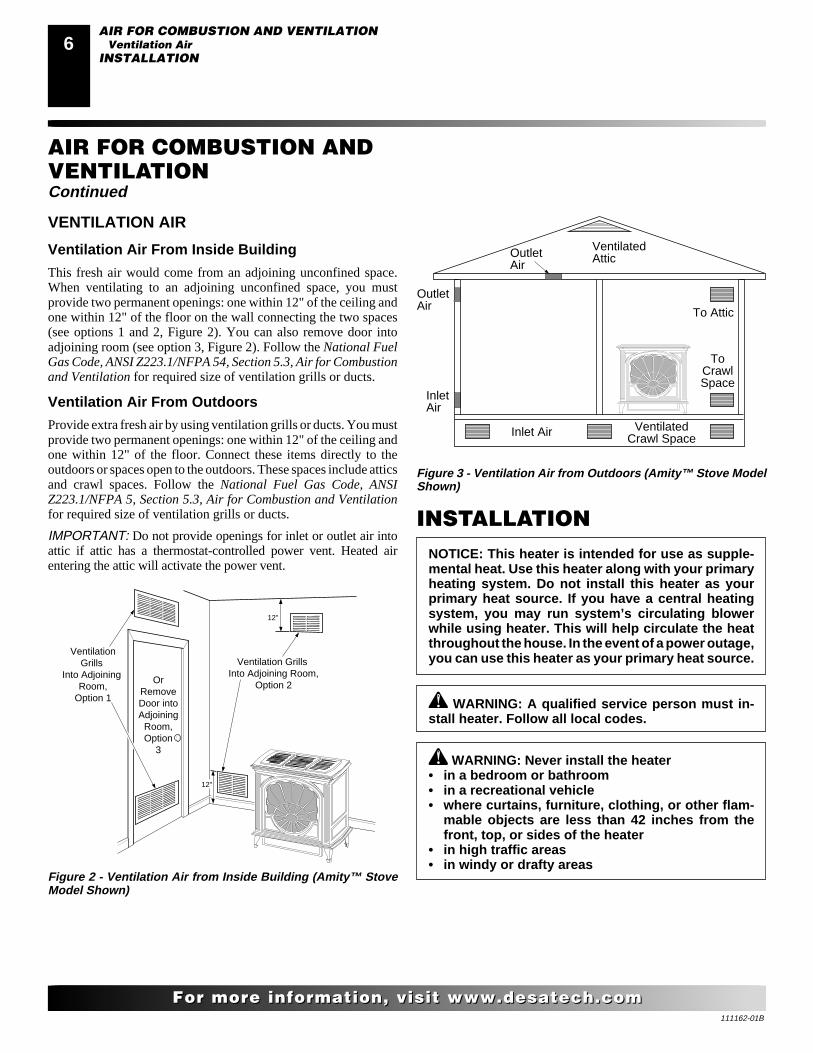
Figure 3 - Ventilation Air from Outdoors (Amity™ Stove ModelShown)
Figure 2 - Ventilation Air from Inside Building (Amity™ StoveModel Shown)
VENTILATION AIR
Ventilation Air From Inside Building
This fresh air would come from an adjoining unconfined space.When ventilating to an adjoining unconfined space, you mustprovide two permanent openings: one within 12" of the ceiling andone within 12" of the floor on the wall connecting the two spaces(see options 1 and 2, Figure 2). You can also remove door intoadjoining room (see option 3, Figure 2). Follow the National FuelGas Code, ANSI Z223.1/NFPA 54, Section 5.3, Air for Combustionand Ventilation for required size of ventilation grills or ducts.
Ventilation Air From Outdoors
Provide extra fresh air by using ventilation grills or ducts. You mustprovide two permanent openings: one within 12" of the ceiling andone within 12" of the floor. Connect these items directly to theoutdoors or spaces open to the outdoors. These spaces include atticsand crawl spaces. Follow the National Fuel Gas Code, ANSIZ223.1/NFPA 5, Section 5.3, Air for Combustion and Ventilationfor required size of ventilation grills or ducts.
IMPORTANT: Do not provide openings for inlet or outlet air intoattic if attic has a thermostat-controlled power vent. Heated airentering the attic will activate the power vent.
OutletAir
VentilatedAttic
OutletAir
InletAir
Inlet Air Ventilated Crawl Space
To CrawlSpace
To Attic
OrRemoveDoor intoAdjoining
Room,Option
3
Ventilation Grills Into Adjoining Room,
Option 2
VentilationGrills
Into Adjoining Room,
Option 1
12"
12"
WARNING: Never install the heater• in a bedroom or bathroom• in a recreational vehicle• where curtains, furniture, clothing, or other flam-
mable objects are less than 42 inches from thefront, top, or sides of the heater
• in high traffic areas• in windy or drafty areas
INSTALLATION
WARNING: A qualified service person must in-stall heater. Follow all local codes.
NOTICE: This heater is intended for use as supple-mental heat. Use this heater along with your primaryheating system. Do not install this heater as yourprimary heat source. If you have a central heatingsystem, you may run system’s circulating blowerwhile using heater. This will help circulate the heatthroughout the house. In the event of a power outage,you can use this heater as your primary heat source.
AIR FOR COMBUSTION AND VENTILATIONVentilation Air
INSTALLATION
111162-01B
77
For more information, visit www.desatech.comFor more information, visit www.desatech.com
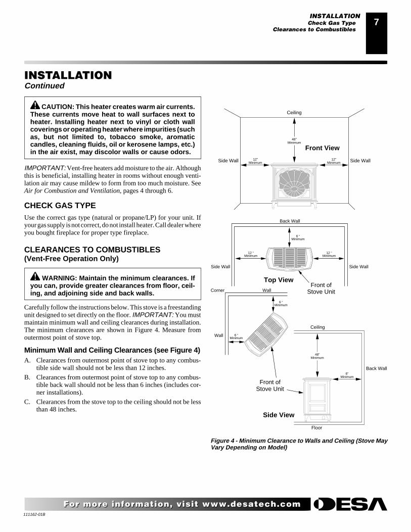
CAUTION: This heater creates warm air currents.These currents move heat to wall surfaces next toheater. Installing heater next to vinyl or cloth wallcoverings or operating heater where impurities (suchas, but not limited to, tobacco smoke, aromaticcandles, cleaning fluids, oil or kerosene lamps, etc.)in the air exist, may discolor walls or cause odors.
INSTALLATIONContinued
CHECK GAS TYPEUse the correct gas type (natural or propane/LP) for your unit. Ifyour gas supply is not correct, do not install heater. Call dealer whereyou bought fireplace for proper type fireplace.
IMPORTANT: Vent-free heaters add moisture to the air. Althoughthis is beneficial, installing heater in rooms without enough venti-lation air may cause mildew to form from too much moisture. SeeAir for Combustion and Ventilation, pages 4 through 6.
CLEARANCES TO COMBUSTIBLES(Vent-Free Operation Only)
WARNING: Maintain the minimum clearances. Ifyou can, provide greater clearances from floor, ceil-ing, and adjoining side and back walls.
Carefully follow the instructions below. This stove is a freestandingunit designed to set directly on the floor. IMPORTANT: You mustmaintain minimum wall and ceiling clearances during installation.The minimum clearances are shown in Figure 4. Measure fromoutermost point of stove top.
Minimum Wall and Ceiling Clearances (see Figure 4)A. Clearances from outermost point of stove top to any combus-
tible side wall should not be less than 12 inches.
B. Clearances from outermost point of stove top to any combus-tible back wall should not be less than 6 inches (includes cor-ner installations).
C. Clearances from the stove top to the ceiling should not be lessthan 48 inches.
Figure 4 - Minimum Clearance to Walls and Ceiling (Stove MayVary Depending on Model)
Top View
Side View
Front ofStove Unit
12"Minimum
12"Minimum
48"Minimum
Ceiling
Side Wall Side Wall
Back Wall
Side Wall Side Wall
12 "Minimum
12 "Minimum
6 "Minimum
6"Minimum
48"Minimum
Ceiling
Floor
Back Wall
Corner
Wall
Wall
6 "Minimum
6 "Minimum
Front ofStove Unit
Front View
INSTALLATIONCheck Gas Type
Clearances to Combustibles
111162-01B
8
For more information, visit www.desatech.comFor more information, visit www.desatech.com
INSTALLATIONContinued
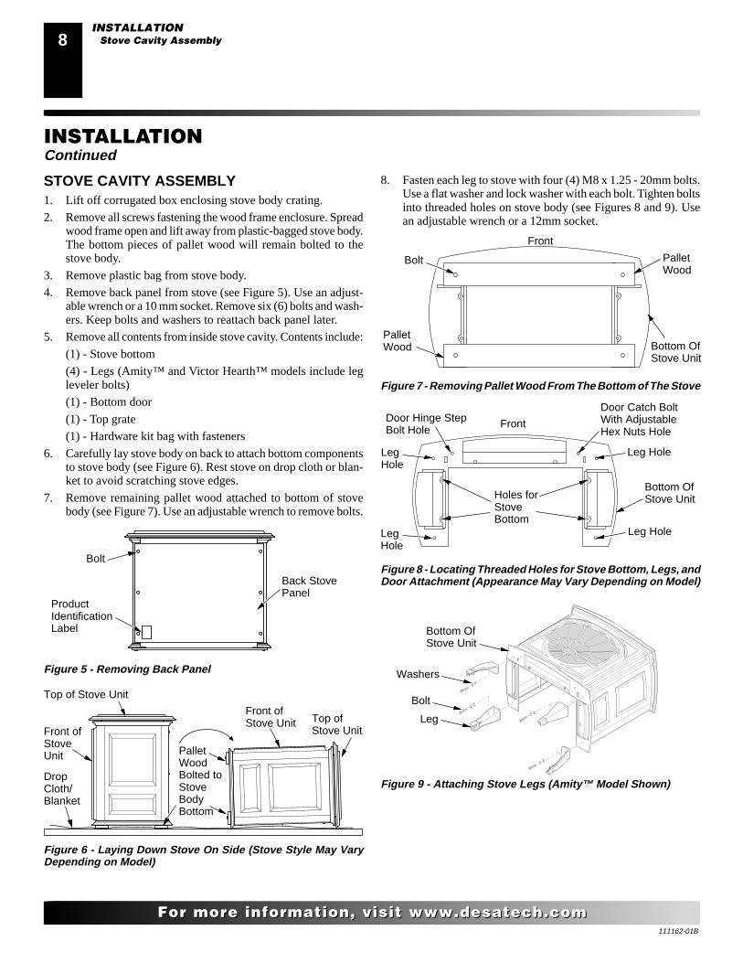
Figure 6 - Laying Down Stove On Side (Stove Style May VaryDepending on Model)
Front ofStoveUnit Pallet
WoodBolted toStoveBodyBottom
Top of Stove Unit
Front ofStove Unit Top of
Stove Unit
DropCloth/Blanket
Figure 7 - Removing Pallet Wood From The Bottom of The Stove
PalletWood
Bolt PalletWood
Bottom OfStove Unit
Front
STOVE CAVITY ASSEMBLY1. Lift off corrugated box enclosing stove body crating.
2. Remove all screws fastening the wood frame enclosure. Spreadwood frame open and lift away from plastic-bagged stove body.The bottom pieces of pallet wood will remain bolted to thestove body.
3. Remove plastic bag from stove body.
4. Remove back panel from stove (see Figure 5). Use an adjust-able wrench or a 10 mm socket. Remove six (6) bolts and wash-ers. Keep bolts and washers to reattach back panel later.
5. Remove all contents from inside stove cavity. Contents include:
(1) - Stove bottom
(4) - Legs (Amity™ and Victor Hearth™ models include legleveler bolts)
(1) - Bottom door
(1) - Top grate
(1) - Hardware kit bag with fasteners
6. Carefully lay stove body on back to attach bottom componentsto stove body (see Figure 6). Rest stove on drop cloth or blan-ket to avoid scratching stove edges.
7. Remove remaining pallet wood attached to bottom of stovebody (see Figure 7). Use an adjustable wrench to remove bolts.
Figure 5 - Removing Back Panel
Bolt
ProductIdentificationLabel
Back StovePanel
Figure 8 - Locating Threaded Holes for Stove Bottom, Legs, andDoor Attachment (Appearance May Vary Depending on Model)
8. Fasten each leg to stove with four (4) M8 x 1.25 - 20mm bolts.Use a flat washer and lock washer with each bolt. Tighten boltsinto threaded holes on stove body (see Figures 8 and 9). Usean adjustable wrench or a 12mm socket.
LegHole
LegHole
Leg Hole
Leg Hole
Door Hinge StepBolt Hole
Door Catch BoltWith AdjustableHex Nuts Hole
Holes forStoveBottom
Front
Bottom OfStove Unit
Figure 9 - Attaching Stove Legs (Amity™ Model Shown)
Bottom OfStove Unit
Leg
Bolt
Washers
INSTALLATIONStove Cavity Assembly
111162-01B
99
For more information, visit www.desatech.comFor more information, visit www.desatech.com
Figure 10 - Attaching Stove Bottom (Amity™ Model Shown)
Bottom OfStove Unit
Bolt
Washers
StoveBottom
INSTALLATIONContinued
INSTALLATIONStove Cavity Assembly (Cont.)
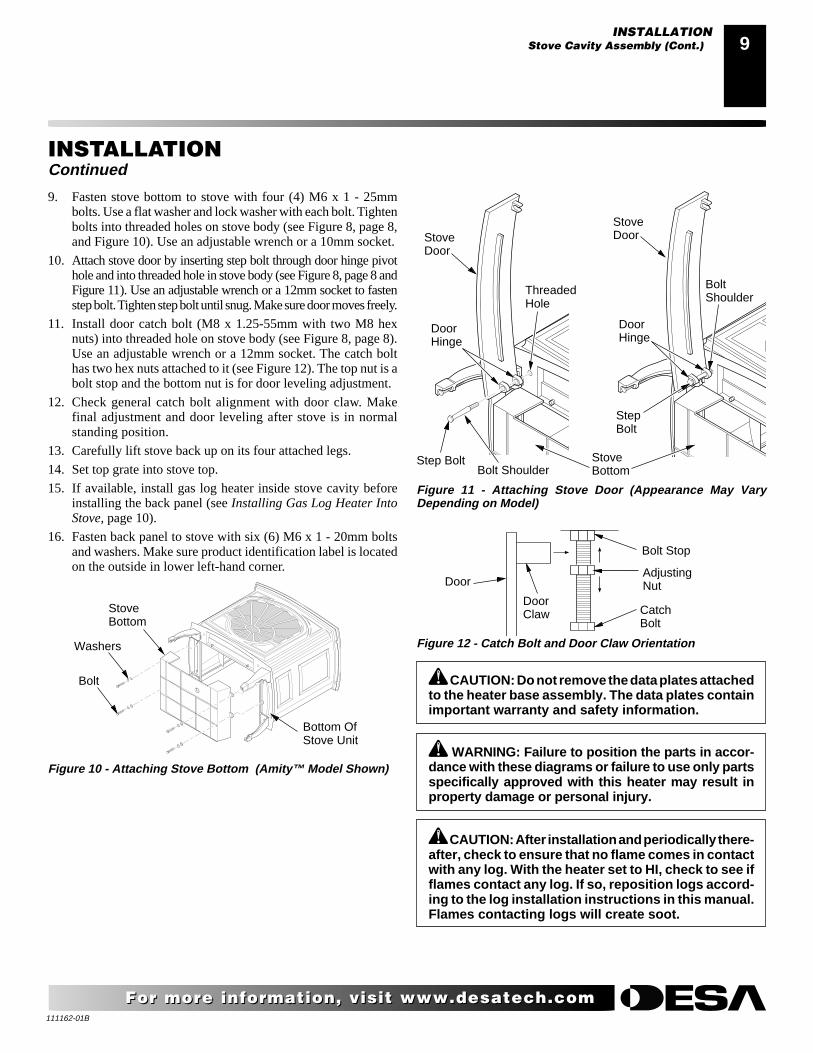
9. Fasten stove bottom to stove with four (4) M6 x 1 - 25mmbolts. Use a flat washer and lock washer with each bolt. Tightenbolts into threaded holes on stove body (see Figure 8, page 8,and Figure 10). Use an adjustable wrench or a 10mm socket.
10. Attach stove door by inserting step bolt through door hinge pivothole and into threaded hole in stove body (see Figure 8, page 8 andFigure 11). Use an adjustable wrench or a 12mm socket to fastenstep bolt. Tighten step bolt until snug. Make sure door moves freely.
11. Install door catch bolt (M8 x 1.25-55mm with two M8 hexnuts) into threaded hole on stove body (see Figure 8, page 8).Use an adjustable wrench or a 12mm socket. The catch bolthas two hex nuts attached to it (see Figure 12). The top nut is abolt stop and the bottom nut is for door leveling adjustment.
12. Check general catch bolt alignment with door claw. Makefinal adjustment and door leveling after stove is in normalstanding position.
13. Carefully lift stove back up on its four attached legs.
14. Set top grate into stove top.
15. If available, install gas log heater inside stove cavity beforeinstalling the back panel (see Installing Gas Log Heater IntoStove, page 10).
16. Fasten back panel to stove with six (6) M6 x 1 - 20mm boltsand washers. Make sure product identification label is locatedon the outside in lower left-hand corner.
CAUTION: Do not remove the data plates attachedto the heater base assembly. The data plates containimportant warranty and safety information.
WARNING: Failure to position the parts in accor-dance with these diagrams or failure to use only partsspecifically approved with this heater may result inproperty damage or personal injury.
CAUTION: After installation and periodically there-after, check to ensure that no flame comes in contactwith any log. With the heater set to HI, check to see ifflames contact any log. If so, reposition logs accord-ing to the log installation instructions in this manual.Flames contacting logs will create soot.
Figure 11 - Attaching Stove Door (Appearance May VaryDepending on Model)
StoveBottom
Step Bolt
DoorHinge
ThreadedHole
StoveDoor
Bolt Shoulder
DoorHinge
StepBolt
BoltShoulder
StoveDoor
Figure 12 - Catch Bolt and Door Claw Orientation
AdjustingNut
Bolt Stop
CatchBolt
DoorClaw
Door
111162-01B
10
For more information, visit www.desatech.comFor more information, visit www.desatech.com
H
I
LO
O
FF
P
ILOT
O
N
INSTALLING GAS LOG HEATER INTO STOVE1. Remove log and gas log heater from carton. Note: Do not pick
up gas log heater by the burner itself. This could damage heater.Always handle the gas log heater by the heater base only.
2. Remove all protective packaging applied to log and gas log heaterfor shipment.
3. Check all items for any shipping damage. If damaged, promptlyinform dealer where you bought heater.
4. If not already removed, remove back panel from assembledstove body (see Figure 5, page 8). Use an adjustable wrench ora 10 mm socket. Remove six (6) bolts and washers. Keep boltsand washers to reattach back panel later.
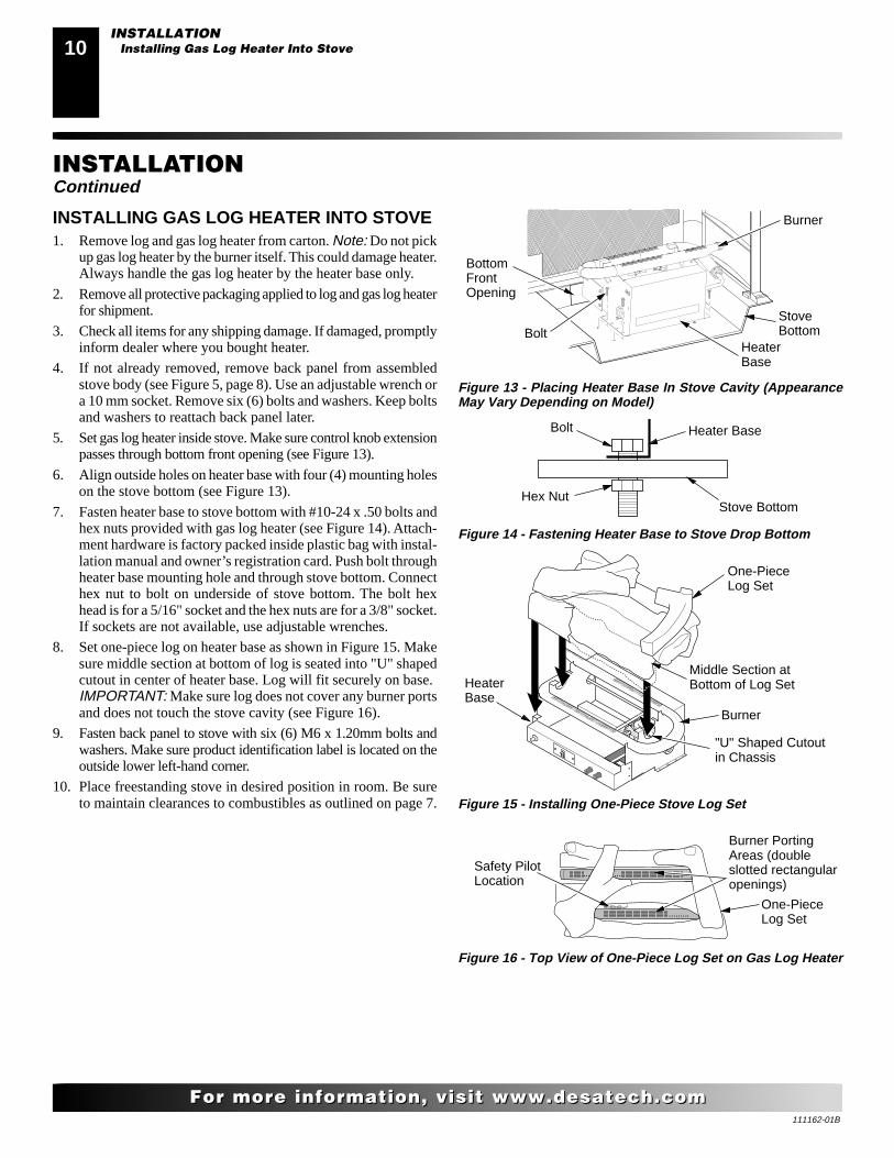
5. Set gas log heater inside stove. Make sure control knob extensionpasses through bottom front opening (see Figure 13).
6. Align outside holes on heater base with four (4) mounting holeson the stove bottom (see Figure 13).
7. Fasten heater base to stove bottom with #10-24 x .50 bolts andhex nuts provided with gas log heater (see Figure 14). Attach-ment hardware is factory packed inside plastic bag with instal-lation manual and owner’s registration card. Push bolt throughheater base mounting hole and through stove bottom. Connecthex nut to bolt on underside of stove bottom. The bolt hexhead is for a 5/16" socket and the hex nuts are for a 3/8" socket.If sockets are not available, use adjustable wrenches.
8. Set one-piece log on heater base as shown in Figure 15. Makesure middle section at bottom of log is seated into "U" shapedcutout in center of heater base. Log will fit securely on base.IMPORTANT: Make sure log does not cover any burner portsand does not touch the stove cavity (see Figure 16).
9. Fasten back panel to stove with six (6) M6 x 1.20mm bolts andwashers. Make sure product identification label is located on theoutside lower left-hand corner.
10. Place freestanding stove in desired position in room. Be sureto maintain clearances to combustibles as outlined on page 7.
INSTALLATIONContinued
Figure 13 - Placing Heater Base In Stove Cavity (AppearanceMay Vary Depending on Model)
Figure 14 - Fastening Heater Base to Stove Drop Bottom
Burner PortingAreas (doubleslotted rectangularopenings)
Figure 16 - Top View of One-Piece Log Set on Gas Log Heater
Safety PilotLocation
One-PieceLog Set
One-PieceLog Set
"U" Shaped Cutoutin Chassis
Burner
Middle Section atBottom of Log Set
Figure 15 - Installing One-Piece Stove Log Set
HeaterBase
BottomFrontOpening
StoveBottom
Burner
BoltHeaterBase
Stove Bottom
Heater BaseBolt
Hex Nut
INSTALLATIONInstalling Gas Log Heater Into Stove
111162-01B
1111
For more information, visit www.desatech.comFor more information, visit www.desatech.com
INSTALLATIONContinued
CONNECTING TO GAS SUPPLY
WARNING: A qualified service person must con-nect heater to gas supply. Follow all local codes.
Installation Items Needed
Before installing heater, make sure you have the items listed below.
• external regulator - propane/LP only (supplied by installer)
• piping (check local codes)
• sealant (resistant to propane/LP gas)
• equipment shutoff valve *
• test gauge connection *
• sediment trap
• tee joint
• pipe wrench
* A CSA design-certified equipment shutoff valve with 1/8" NPTtap is an acceptable alternative to test gauge connection. Purchasethe optional CSA design-certified equipment shutoff valve fromyour dealer. See Accessories, page 26.
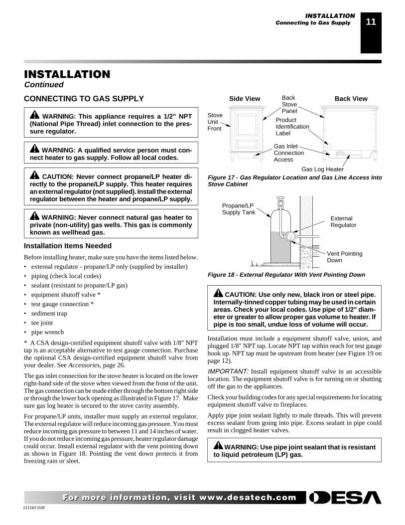
The gas inlet connection for the stove heater is located on the lowerright-hand side of the stove when viewed from the front of the unit.The gas connection can be made either through the bottom right sideor through the lower back opening as illustrated in Figure 17. Makesure gas log heater is secured to the stove cavity assembly.
For propane/LP units, installer must supply an external regulator.The external regulator will reduce incoming gas pressure. You mustreduce incoming gas pressure to between 11 and 14 inches of water.If you do not reduce incoming gas pressure, heater regulator damagecould occur. Install external regulator with the vent pointing downas shown in Figure 18. Pointing the vent down protects it fromfreezing rain or sleet.
CAUTION: Never connect propane/LP heater di-rectly to the propane/LP supply. This heater requiresan external regulator (not supplied). Install the externalregulator between the heater and propane/LP supply.
WARNING: This appliance requires a 1/2" NPT(National Pipe Thread) inlet connection to the pres-sure regulator.
WARNING: Never connect natural gas heater toprivate (non-utility) gas wells. This gas is commonlyknown as wellhead gas.
Figure 17 - Gas Regulator Location and Gas Line Access IntoStove Cabinet
Gas InletConnectionAccess
ProductIdentificationLabel
Gas Log Heater
Back ViewSide View
Figure 18 - External Regulator With Vent Pointing Down
BackStovePanel
StoveUnitFront
Propane/LPSupply Tank
ExternalRegulator
Vent PointingDown
CAUTION: Use only new, black iron or steel pipe.Internally-tinned copper tubing may be used in certainareas. Check your local codes. Use pipe of 1/2" diam-eter or greater to allow proper gas volume to heater. Ifpipe is too small, undue loss of volume will occur.
Installation must include a equipment shutoff valve, union, andplugged 1/8" NPT tap. Locate NPT tap within reach for test gaugehook up. NPT tap must be upstream from heater (see Figure 19 onpage 12).
IMPORTANT: Install equipment shutoff valve in an accessiblelocation. The equipment shutoff valve is for turning on or shuttingoff the gas to the appliances.
Check your building codes for any special requirements for locatingequipment shutoff valve to fireplaces.
Apply pipe joint sealant lightly to male threads. This will preventexcess sealant from going into pipe. Excess sealant in pipe couldresult in clogged heater valves.
WARNING: Use pipe joint sealant that is resistantto liquid petroleum (LP) gas.
INSTALLATIONConnecting to Gas Supply
111162-01B
12
For more information, visit www.desatech.comFor more information, visit www.desatech.com
* Purchase the optional CSA design-certified equipment shutoffvalve from your dealer. See Accessories, page 26.
** Minimum inlet pressure for purpose of input adjustment.
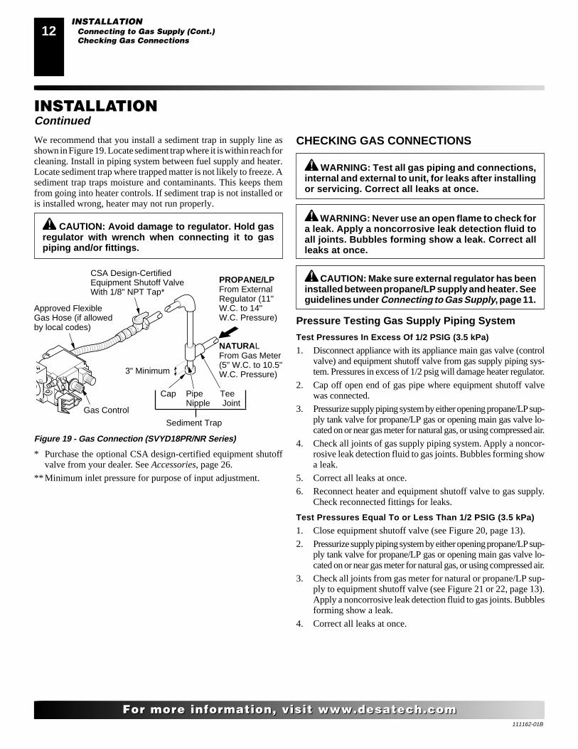
Figure 19 - Gas Connection (SVYD18PR/NR Series)
3" Minimum
Sediment Trap
Gas Control
CSA Design-CertifiedEquipment Shutoff ValveWith 1/8" NPT Tap*
Approved FlexibleGas Hose (if allowedby local codes)
Cap Pipe TeeNipple Joint
INSTALLATIONContinued
PROPANE/LPFrom ExternalRegulator (11"W.C. to 14"W.C. Pressure)
NATURALFrom Gas Meter(5" W.C. to 10.5"W.C. Pressure)
CAUTION: Avoid damage to regulator. Hold gasregulator with wrench when connecting it to gaspiping and/or fittings.
We recommend that you install a sediment trap in supply line asshown in Figure 19. Locate sediment trap where it is within reach forcleaning. Install in piping system between fuel supply and heater.Locate sediment trap where trapped matter is not likely to freeze. Asediment trap traps moisture and contaminants. This keeps themfrom going into heater controls. If sediment trap is not installed oris installed wrong, heater may not run properly.
WARNING: Never use an open flame to check fora leak. Apply a noncorrosive leak detection fluid toall joints. Bubbles forming show a leak. Correct allleaks at once.
WARNING: Test all gas piping and connections,internal and external to unit, for leaks after installingor servicing. Correct all leaks at once.
CHECKING GAS CONNECTIONS
Pressure Testing Gas Supply Piping System
Test Pressures In Excess Of 1/2 PSIG (3.5 kPa)
1. Disconnect appliance with its appliance main gas valve (controlvalve) and equipment shutoff valve from gas supply piping sys-tem. Pressures in excess of 1/2 psig will damage heater regulator.
2. Cap off open end of gas pipe where equipment shutoff valvewas connected.
3. Pressurize supply piping system by either opening propane/LP sup-ply tank valve for propane/LP gas or opening main gas valve lo-cated on or near gas meter for natural gas, or using compressed air.
4. Check all joints of gas supply piping system. Apply a noncor-rosive leak detection fluid to gas joints. Bubbles forming showa leak.
5. Correct all leaks at once.
6. Reconnect heater and equipment shutoff valve to gas supply.Check reconnected fittings for leaks.
Test Pressures Equal To or Less Than 1/2 PSIG (3.5 kPa)
1. Close equipment shutoff valve (see Figure 20, page 13).
2. Pressurize supply piping system by either opening propane/LP sup-ply tank valve for propane/LP gas or opening main gas valve lo-cated on or near gas meter for natural gas, or using compressed air.
3. Check all joints from gas meter for natural or propane/LP sup-ply to equipment shutoff valve (see Figure 21 or 22, page 13).Apply a noncorrosive leak detection fluid to gas joints. Bubblesforming show a leak.
4. Correct all leaks at once.
CAUTION: Make sure external regulator has beeninstalled between propane/LP supply and heater. Seeguidelines under Connecting to Gas Supply, page 11.
INSTALLATIONConnecting to Gas Supply (Cont.)Checking Gas Connections
111162-01B
1313
For more information, visit www.desatech.comFor more information, visit www.desatech.com
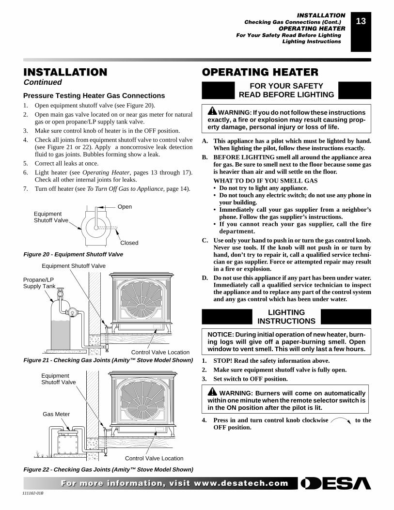
Pressure Testing Heater Gas Connections1. Open equipment shutoff valve (see Figure 20).
2. Open main gas valve located on or near gas meter for naturalgas or open propane/LP supply tank valve.
3. Make sure control knob of heater is in the OFF position.
4. Check all joints from equipment shutoff valve to control valve(see Figure 21 or 22). Apply a noncorrosive leak detectionfluid to gas joints. Bubbles forming show a leak.
5. Correct all leaks at once.
6. Light heater (see Operating Heater, pages 13 through 17).Check all other internal joints for leaks.
7. Turn off heater (see To Turn Off Gas to Appliance, page 14).
INSTALLATIONContinued
Figure 20 - Equipment Shutoff Valve
EquipmentShutoff Valve
Figure 21 - Checking Gas Joints (Amity™ Stove Model Shown)
ONPOSIT
OPOSClosed
Open
Control Valve Location
Propane/LPSupply Tank
Equipment Shutoff Valve
Figure 22 - Checking Gas Joints (Amity™ Stove Model Shown)
Gas Meter
EquipmentShutoff Valve
Control Valve Location
OPERATING HEATERFOR YOUR SAFETY
READ BEFORE LIGHTING
WARNING: If you do not follow these instructionsexactly, a fire or explosion may result causing prop-erty damage, personal injury or loss of life.
A. This appliance has a pilot which must be lighted by hand.When lighting the pilot, follow these instructions exactly.
B. BEFORE LIGHTING smell all around the appliance areafor gas. Be sure to smell next to the floor because some gasis heavier than air and will settle on the floor.WHAT TO DO IF YOU SMELL GAS• Do not try to light any appliance.• Do not touch any electric switch; do not use any phone in
your building.• Immediately call your gas supplier from a neighbor’s
phone. Follow the gas supplier’s instructions.• If you cannot reach your gas supplier, call the fire
department.C. Use only your hand to push in or turn the gas control knob.
Never use tools. If the knob will not push in or turn byhand, don’t try to repair it, call a qualified service techni-cian or gas supplier. Force or attempted repair may resultin a fire or explosion.
D. Do not use this appliance if any part has been under water.Immediately call a qualified service technician to inspectthe appliance and to replace any part of the control systemand any gas control which has been under water.
LIGHTINGINSTRUCTIONS
NOTICE: During initial operation of new heater, burn-ing logs will give off a paper-burning smell. Openwindow to vent smell. This will only last a few hours.
1. STOP! Read the safety information above.2. Make sure equipment shutoff valve is fully open.3. Set switch to OFF position.
WARNING: Burners will come on automaticallywithin one minute when the remote selector switch isin the ON position after the pilot is lit.
4. Press in and turn control knob clockwise to theOFF position.
INSTALLATIONChecking Gas Connections (Cont.)
OPERATING HEATERFor Your Safety Read Before Lighting
Lighting Instructions
111162-01B
14
For more information, visit www.desatech.comFor more information, visit www.desatech.com
5. Wait five (5) minutes to clear out any gas. Then smell forgas, including near the floor. If you smell gas, STOP! Fol-low “B” in the safety information in column 2, page 13. Ifyou don’t smell gas, go to the next step.
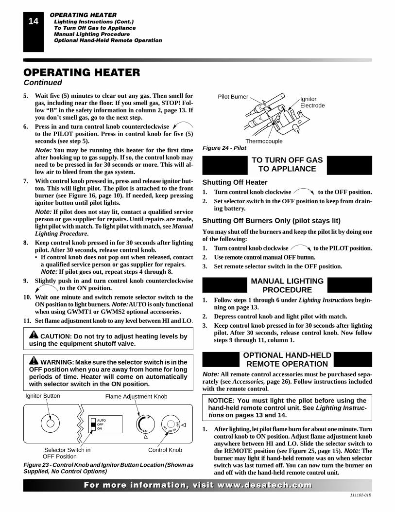
6. Press in and turn control knob counterclockwise to the PILOT position. Press in control knob for five (5)seconds (see step 5).Note: You may be running this heater for the first timeafter hooking up to gas supply. If so, the control knob mayneed to be pressed in for 30 seconds or more. This will al-low air to bleed from the gas system.
7. With control knob pressed in, press and release ignitor but-ton. This will light pilot. The pilot is attached to the frontburner (see Figure 16, page 10). If needed, keep pressingignitor button until pilot lights.Note: If pilot does not stay lit, contact a qualified serviceperson or gas supplier for repairs. Until repairs are made,light pilot with match. To light pilot with match, see ManualLighting Procedure.
8. Keep control knob pressed in for 30 seconds after lightingpilot. After 30 seconds, release control knob.• If control knob does not pop out when released, contact
a qualified service person or gas supplier for repairs.Note: If pilot goes out, repeat steps 4 through 8.
9. Slightly push in and turn control knob counterclockwise to the ON position.
10. Wait one minute and switch remote selector switch to theON position to light burners. Note: AUTO is only functionalwhen using GWMT1 or GWMS2 optional accessories.
11. Set flame adjustment knob to any level between HI and LO.
CAUTION: Do not try to adjust heating levels byusing the equipment shutoff valve.
WARNING: Make sure the selector switch is in theOFF position when you are away from home for longperiods of time. Heater will come on automaticallywith selector switch in the ON position.
OPERATING HEATERContinued
OFF
PILOTON
L O
IH
AUTOOFFON
Figure 23 - Control Knob and Ignitor Button Location (Shown asSupplied, No Control Options)
Control Knob
Ignitor Button
Selector Switch inOFF Position
Flame Adjustment Knob
IgnitorElectrode
Pilot Burner
Figure 24 - PilotThermocouple
TO TURN OFF GASTO APPLIANCE
Shutting Off Heater1. Turn control knob clockwise to the OFF position.2. Set selector switch in the OFF position to keep from drain-
ing battery.
Shutting Off Burners Only (pilot stays lit)
You may shut off the burners and keep the pilot lit by doing oneof the following:1. Turn control knob clockwise to the PILOT position.2. Use remote control manual OFF button.3. Set remote selector switch in the OFF position.
MANUAL LIGHTINGPROCEDURE
1. Follow steps 1 through 6 under Lighting Instructions begin-ning on page 13.
2. Depress control knob and light pilot with match.3. Keep control knob pressed in for 30 seconds after lighting
pilot. After 30 seconds, release control knob. Now followsteps 9 through 11, column 1.
OPTIONAL HAND-HELDREMOTE OPERATION
OPERATING HEATERLighting Instructions (Cont.)To Turn Off Gas to ApplianceManual Lighting ProcedureOptional Hand-Held Remote Operation
NOTICE: You must light the pilot before using thehand-held remote control unit. See Lighting Instruc-tions on pages 13 and 14.
Note: All remote control accessories must be purchased sepa-rately (see Accessories, page 26). Follow instructions includedwith the remote control.
1. After lighting, let pilot flame burn for about one minute. Turncontrol knob to ON position. Adjust flame adjustment knobanywhere between HI and LO. Slide the selector switch tothe REMOTE position (see Figure 25, page 15). Note: Theburner may light if hand-held remote was on when selectorswitch was last turned off. You can now turn the burner onand off with the hand-held remote control unit.
111162-01B
1515
For more information, visit www.desatech.comFor more information, visit www.desatech.com
ONOFFREMOTE
OFF
PILOTO
N
L O
IH
OPERATING HEATERContinued
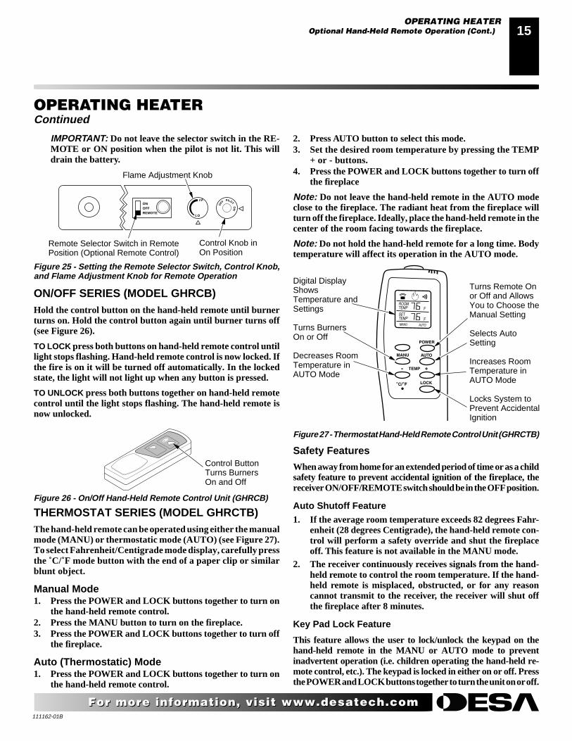
Figure 25 - Setting the Remote Selector Switch, Control Knob,and Flame Adjustment Knob for Remote Operation
Remote Selector Switch in RemotePosition (Optional Remote Control)
Control Knob inOn Position
Flame Adjustment Knob
OPERATING HEATEROptional Hand-Held Remote Operation (Cont.)
Figure 26 - On/Off Hand-Held Remote Control Unit (GHRCB)
Control ButtonTurns BurnersOn and Off
Figure 27 - Thermostat Hand-Held Remote Control Unit (GHRCTB)
Turns Remote Onor Off and AllowsYou to Choose theManual Setting
Selects AutoSetting
Increases RoomTemperature inAUTO Mode
Locks System toPrevent AccidentalIgnition
Digital DisplayShowsTemperature andSettings
Turns BurnersOn or Off
Decreases RoomTemperature inAUTO Mode
IMPORTANT: Do not leave the selector switch in the RE-MOTE or ON position when the pilot is not lit. This willdrain the battery.
ON/OFF SERIES (MODEL GHRCB)Hold the control button on the hand-held remote until burnerturns on. Hold the control button again until burner turns off(see Figure 26).
TO LOCK press both buttons on hand-held remote control untillight stops flashing. Hand-held remote control is now locked. Ifthe fire is on it will be turned off automatically. In the lockedstate, the light will not light up when any button is pressed.
TO UNLOCK press both buttons together on hand-held remotecontrol until the light stops flashing. The hand-held remote isnow unlocked.
THERMOSTAT SERIES (MODEL GHRCTB)The hand-held remote can be operated using either the manualmode (MANU) or thermostatic mode (AUTO) (see Figure 27).To select Fahrenheit/Centigrade mode display, carefully pressthe ˚C/˚F mode button with the end of a paper clip or similarblunt object.
Manual Mode1. Press the POWER and LOCK buttons together to turn on
the hand-held remote control.2. Press the MANU button to turn on the fireplace.3. Press the POWER and LOCK buttons together to turn off
the fireplace.
Auto (Thermostatic) Mode1. Press the POWER and LOCK buttons together to turn on
the hand-held remote control.
Safety Features
When away from home for an extended period of time or as a childsafety feature to prevent accidental ignition of the fireplace, thereceiver ON/OFF/REMOTE switch should be in the OFF position.
Auto Shutoff Feature1. If the average room temperature exceeds 82 degrees Fahr-
enheit (28 degrees Centigrade), the hand-held remote con-trol will perform a safety override and shut the fireplaceoff. This feature is not available in the MANU mode.
2. The receiver continuously receives signals from the hand-held remote to control the room temperature. If the hand-held remote is misplaced, obstructed, or for any reasoncannot transmit to the receiver, the receiver will shut offthe fireplace after 8 minutes.
Key Pad Lock Feature
This feature allows the user to lock/unlock the keypad on thehand-held remote in the MANU or AUTO mode to preventinadvertent operation (i.e. children operating the hand-held re-mote control, etc.). The keypad is locked in either on or off. Pressthe POWER and LOCK buttons together to turn the unit on or off.
2. Press AUTO button to select this mode.3. Set the desired room temperature by pressing the TEMP
+ or - buttons.4. Press the POWER and LOCK buttons together to turn off
the fireplace
Note: Do not leave the hand-held remote in the AUTO modeclose to the fireplace. The radiant heat from the fireplace willturn off the fireplace. Ideally, place the hand-held remote in thecenter of the room facing towards the fireplace.
Note: Do not hold the hand-held remote for a long time. Bodytemperature will affect its operation in the AUTO mode.
111162-01B
16
For more information, visit www.desatech.comFor more information, visit www.desatech.com
Pilot Burner
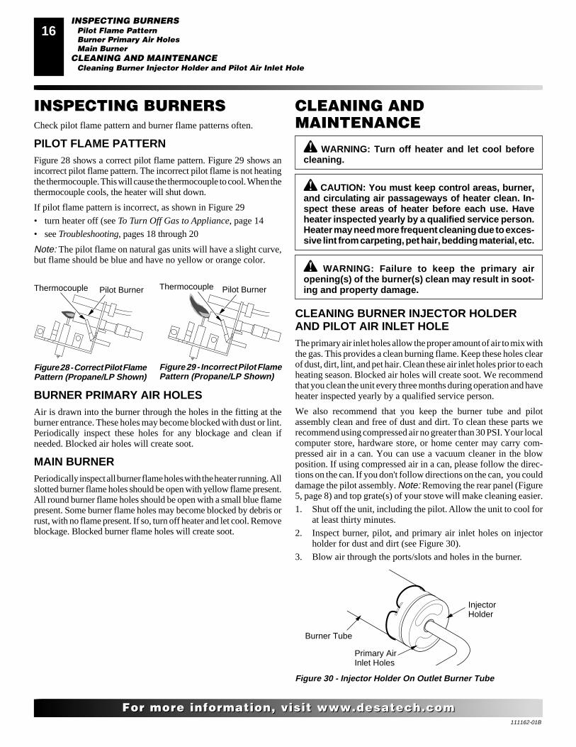
Figure 28 - Correct Pilot FlamePattern (Propane/LP Shown)
Figure 29 - Incorrect Pilot FlamePattern (Propane/LP Shown)
INSPECTING BURNERSCheck pilot flame pattern and burner flame patterns often.
PILOT FLAME PATTERNFigure 28 shows a correct pilot flame pattern. Figure 29 shows anincorrect pilot flame pattern. The incorrect pilot flame is not heatingthe thermocouple. This will cause the thermocouple to cool. When thethermocouple cools, the heater will shut down.
If pilot flame pattern is incorrect, as shown in Figure 29
• turn heater off (see To Turn Off Gas to Appliance, page 14
• see Troubleshooting, pages 18 through 20
Note: The pilot flame on natural gas units will have a slight curve,but flame should be blue and have no yellow or orange color.
Thermocouple Pilot BurnerThermocouple
BURNER PRIMARY AIR HOLESAir is drawn into the burner through the holes in the fitting at theburner entrance. These holes may become blocked with dust or lint.Periodically inspect these holes for any blockage and clean ifneeded. Blocked air holes will create soot.
MAIN BURNERPeriodically inspect all burner flame holes with the heater running. Allslotted burner flame holes should be open with yellow flame present.All round burner flame holes should be open with a small blue flamepresent. Some burner flame holes may become blocked by debris orrust, with no flame present. If so, turn off heater and let cool. Removeblockage. Blocked burner flame holes will create soot.
INSPECTING BURNERSPilot Flame PatternBurner Primary Air HolesMain Burner
CLEANING AND MAINTENANCECleaning Burner Injector Holder and Pilot Air Inlet Hole
Figure 30 - Injector Holder On Outlet Burner Tube
Burner Tube
InjectorHolder
Primary AirInlet Holes
CLEANING ANDMAINTENANCE
WARNING: Turn off heater and let cool beforecleaning.
CAUTION: You must keep control areas, burner,and circulating air passageways of heater clean. In-spect these areas of heater before each use. Haveheater inspected yearly by a qualified service person.Heater may need more frequent cleaning due to exces-sive lint from carpeting, pet hair, bedding material, etc.
CLEANING BURNER INJECTOR HOLDERAND PILOT AIR INLET HOLEThe primary air inlet holes allow the proper amount of air to mix withthe gas. This provides a clean burning flame. Keep these holes clearof dust, dirt, lint, and pet hair. Clean these air inlet holes prior to eachheating season. Blocked air holes will create soot. We recommendthat you clean the unit every three months during operation and haveheater inspected yearly by a qualified service person.
We also recommend that you keep the burner tube and pilotassembly clean and free of dust and dirt. To clean these parts werecommend using compressed air no greater than 30 PSI. Your localcomputer store, hardware store, or home center may carry com-pressed air in a can. You can use a vacuum cleaner in the blowposition. If using compressed air in a can, please follow the direc-tions on the can. If you don't follow directions on the can, you coulddamage the pilot assembly. Note: Removing the rear panel (Figure5, page 8) and top grate(s) of your stove will make cleaning easier.
1. Shut off the unit, including the pilot. Allow the unit to cool forat least thirty minutes.
2. Inspect burner, pilot, and primary air inlet holes on injectorholder for dust and dirt (see Figure 30).
3. Blow air through the ports/slots and holes in the burner.
WARNING: Failure to keep the primary airopening(s) of the burner(s) clean may result in soot-ing and property damage.
111162-01B
1717
For more information, visit www.desatech.comFor more information, visit www.desatech.com
LOGS• If you remove logs for cleaning, refer to Installing Gas Log
Heater Into Stove, page 10, to properly replace logs.
• Replace log(s) if broken or chipped (dime-sized or larger).
Burner Tube
Pilot Assembly
Pilot AirInlet Hole
Ports/Slots
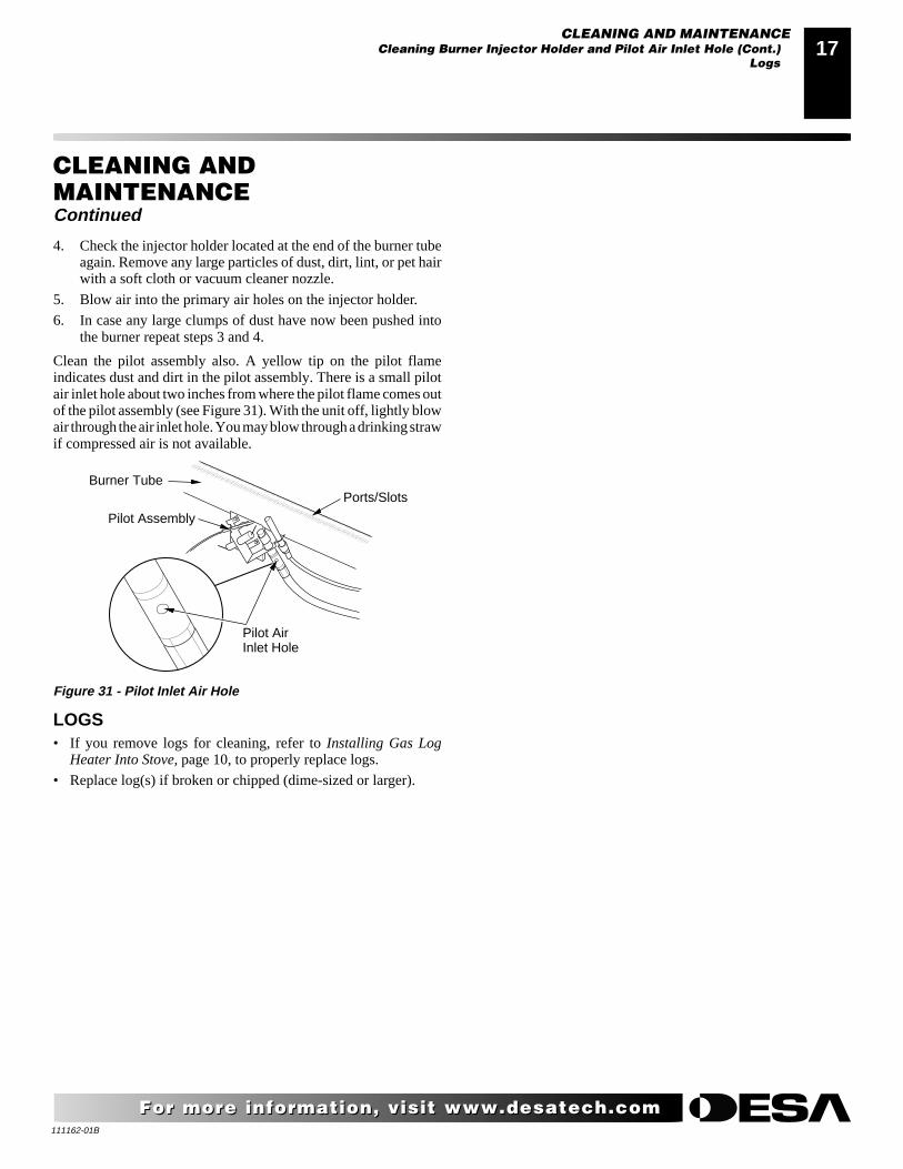
Figure 31 - Pilot Inlet Air Hole
CLEANING AND MAINTENANCECleaning Burner Injector Holder and Pilot Air Inlet Hole (Cont.)
Logs
4. Check the injector holder located at the end of the burner tubeagain. Remove any large particles of dust, dirt, lint, or pet hairwith a soft cloth or vacuum cleaner nozzle.
5. Blow air into the primary air holes on the injector holder.
6. In case any large clumps of dust have now been pushed intothe burner repeat steps 3 and 4.
Clean the pilot assembly also. A yellow tip on the pilot flameindicates dust and dirt in the pilot assembly. There is a small pilotair inlet hole about two inches from where the pilot flame comes outof the pilot assembly (see Figure 31). With the unit off, lightly blowair through the air inlet hole. You may blow through a drinking strawif compressed air is not available.
CLEANING ANDMAINTENANCEContinued
111162-01B
18
For more information, visit www.desatech.comFor more information, visit www.desatech.com
TROUBLESHOOTING
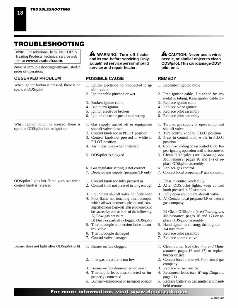
WARNING: Turn off heaterand let cool before servicing. Onlya qualified service person shouldservice and repair heater.
CAUTION: Never use a wire,needle, or similar object to cleanODS/pilot. This can damage ODS/pilot unit.
POSSIBLE CAUSE
1. Ignitor electrode not connected to ig-nitor cable
2. Ignitor cable pinched or wet
3. Broken ignitor cable4. Bad piezo ignitor5. Ignitor electrode broken6. Ignitor electrode positioned wrong
1. Gas supply turned off or equipmentshutoff valve closed
2. Control knob not in PILOT position3. Control knob not pressed in while in
PILOT position4. Air in gas lines when installed
5. ODS/pilot is clogged
6. Gas regulator setting is not correct7. Depleted gas supply (propane/LP only)
1. Control knob not fully pressed in2. Control knob not pressed in long enough
3. Equipment shutoff valve not fully open4. Pilot flame not touching thermocouple,
which allows thermocouple to cool, caus-ing pilot flame to go out. This problem couldbe caused by one or both of the following:A) Low gas pressureB) Dirty or partially clogged ODS/pilot
5. Thermocouple connection loose at con-trol valve
6. Thermocouple damaged7. Control valve damaged
1. Burner orifice clogged
2. Inlet gas pressure is too low
3. Burner orifice diameter is too small4. Thermopile leads disconnected or im-
properly connected5. Burners will not come on in remote position
REMEDY
1. Reconnect ignitor cable
2. Free ignitor cable if pinched by anymetal or tubing. Keep ignitor cable dry
3. Replace ignitor cable4. Replace piezo ignitor5. Replace pilot assembly6. Replace pilot assembly
1. Turn on gas supply or open equipmentshutoff valve
2. Turn control knob to PILOT position3. Press in control knob while in PILOT
position4. Continue holding down control knob. Re-
peat igniting operation until air is removed5. Clean ODS/pilot (see Cleaning and
Maintenance, pages 16 and 17) or re-place ODS/pilot assembly
6. Replace gas control7. Contact local propane/LP gas company
1. Press in control knob fully2. After ODS/pilot lights, keep control
knob pressed in 30 seconds3. Fully open equipment shutoff valve4. A) Contact local propane/LP or natural
gas company
B) Clean ODS/pilot (see Cleaning andMaintenance, pages 16 and 17) or re-place ODS/pilot assembly
5. Hand tighten until snug, then tighten1/4 turn more
6. Replace pilot assembly7. Replace control valve
1. Clean burner (see Cleaning and Main-tenance, pages 16 and 17) or replaceburner orifice
2. Contact local propane/LP or natural gascompany
3. Replace burner orifice4. Reconnect leads (see Wiring Diagram,
page 21)5. Replace battery in transmitter and hand-
held remote
OBSERVED PROBLEM
When ignitor button is pressed, there is nospark at ODS/pilot
When ignitor button is pressed, there isspark at ODS/pilot but no ignition
ODS/pilot lights but flame goes out whencontrol knob is released
Burner does not light after ODS/pilot is lit
Note: For additional help, visit DESAHeating Products’ technical service website at www.desatech.com.
Note: All troubleshooting items are listed inorder of operation.
TROUBLESHOOTING
111162-01B
1919
For more information, visit www.desatech.comFor more information, visit www.desatech.com
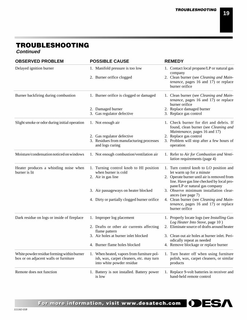
OBSERVED PROBLEM
Delayed ignition burner
Burner backfiring during combustion
Slight smoke or odor during initial operation
Moisture/condensation noticed on windows
Heater produces a whistling noise whenburner is lit
Dark residue on logs or inside of fireplace
White powder residue forming within burnerbox or on adjacent walls or furniture
Remote does not function
REMEDY
1. Contact local propane/LP or natural gascompany
2. Clean burner (see Cleaning and Main-tenance, pages 16 and 17) or replaceburner orifice
1. Clean burner (see Cleaning and Main-tenance, pages 16 and 17) or replaceburner orifice
2. Replace damaged burner3. Replace gas control
1. Check burner for dirt and debris. Iffound, clean burner (see Cleaning andMaintenance, pages 16 and 17)
2. Replace gas control3. Problem will stop after a few hours of
operation
1. Refer to Air for Combustion and Venti-lation requirements (page 4)
1. Turn control knob to LO position andlet warm up for a minute
2. Operate burner until air is removed fromline. Have gas line checked by local pro-pane/LP or natural gas company
3. Observe minimum installation clear-ances (see page 7)
4. Clean burner (see Cleaning and Main-tenance, pages 16 and 17) or replaceburner orifice
1. Properly locate logs (see Installing GasLog Heater Into Stove, page 10 )
2. Eliminate source of drafts around heater
3. Clean out air holes at burner inlet. Peri-odically repeat as needed
4. Remove blockage or replace burner
1. Turn heater off when using furniturepolish, wax, carpet cleaners, or similarproducts
1. Replace 9-volt batteries in receiver andhand-held remote control
TROUBLESHOOTINGContinued
POSSIBLE CAUSE
1. Manifold pressure is too low
2. Burner orifice clogged
1. Burner orifice is clogged or damaged
2. Damaged burner3. Gas regulator defective
1. Not enough air
2. Gas regulator defective3. Residues from manufacturing processes
and logs curing
1. Not enough combustion/ventilation air
1. Turning control knob to HI positionwhen burner is cold
2. Air in gas line
3. Air passageways on heater blocked
4. Dirty or partially clogged burner orifice
1. Improper log placement
2. Drafts or other air currents affectingflame pattern
3. Air holes at burner inlet blocked
4. Burner flame holes blocked
1. When heated, vapors from furniture pol-ish, wax, carpet cleaners, etc. may turninto white powder residue
1. Battery is not installed. Battery poweris low
TROUBLESHOOTING
111162-01B
20
For more information, visit www.desatech.comFor more information, visit www.desatech.com
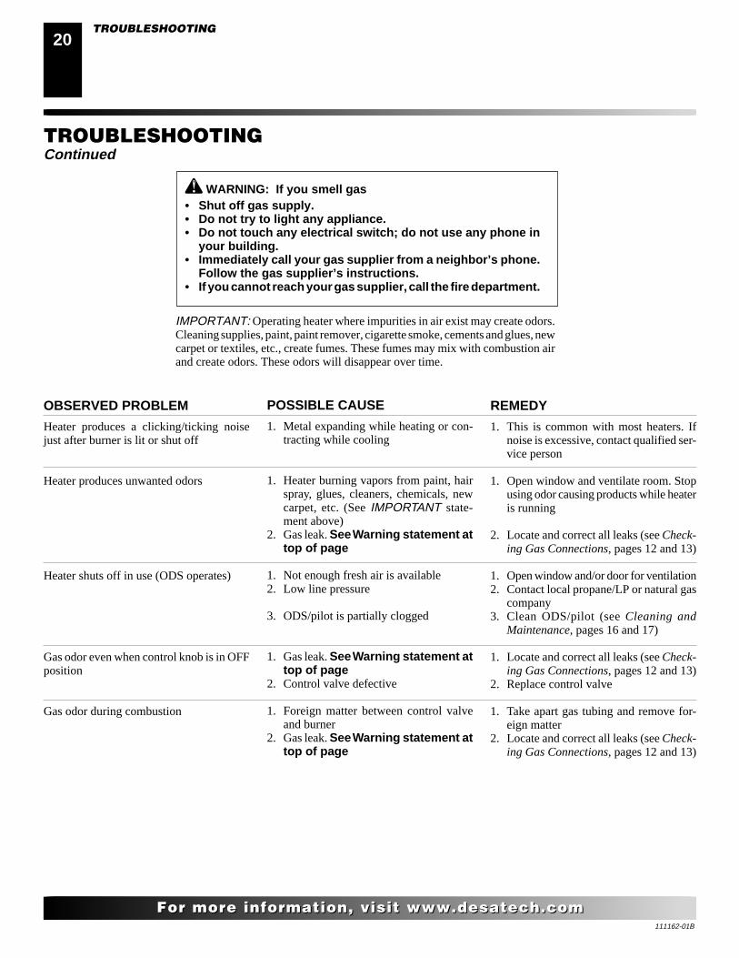
WARNING: If you smell gas• Shut off gas supply.• Do not try to light any appliance.• Do not touch any electrical switch; do not use any phone in
your building.• Immediately call your gas supplier from a neighbor’s phone.
Follow the gas supplier’s instructions.• If you cannot reach your gas supplier, call the fire department.
POSSIBLE CAUSE
1. Metal expanding while heating or con-tracting while cooling
1. Heater burning vapors from paint, hairspray, glues, cleaners, chemicals, newcarpet, etc. (See IMPORTANT state-ment above)
2. Gas leak. See Warning statement attop of page
1. Not enough fresh air is available2. Low line pressure
3. ODS/pilot is partially clogged
1. Gas leak. See Warning statement attop of page
2. Control valve defective
1. Foreign matter between control valveand burner
2. Gas leak. See Warning statement attop of page
OBSERVED PROBLEM
Heater produces a clicking/ticking noisejust after burner is lit or shut off
Heater produces unwanted odors
Heater shuts off in use (ODS operates)
Gas odor even when control knob is in OFFposition
Gas odor during combustion
REMEDY
1. This is common with most heaters. Ifnoise is excessive, contact qualified ser-vice person
1. Open window and ventilate room. Stopusing odor causing products while heateris running
2. Locate and correct all leaks (see Check-ing Gas Connections, pages 12 and 13)
1. Open window and/or door for ventilation2. Contact local propane/LP or natural gas
company3. Clean ODS/pilot (see Cleaning and
Maintenance, pages 16 and 17)
1. Locate and correct all leaks (see Check-ing Gas Connections, pages 12 and 13)
2. Replace control valve
1. Take apart gas tubing and remove for-eign matter
2. Locate and correct all leaks (see Check-ing Gas Connections, pages 12 and 13)
IMPORTANT: Operating heater where impurities in air exist may create odors.Cleaning supplies, paint, paint remover, cigarette smoke, cements and glues, newcarpet or textiles, etc., create fumes. These fumes may mix with combustion airand create odors. These odors will disappear over time.
TROUBLESHOOTINGContinued
TROUBLESHOOTING
111162-01B
2121
For more information, visit www.desatech.comFor more information, visit www.desatech.com
SPECIFICATIONSSVYD18PR SVYD18NR
Btu (Variable) 16,000/30,000 16,000/30,000Type Gas Propane/LP Only Natural OnlyIgnition Piezo PiezoPressure Manifold 8" W.C. 3.5" W.C.Inlet Gas Pressure (in. of water)
Maximum 14" 10.5"Minimum* 11" 5"
Shipping Weight 28 lbs. 28 lbs.* For input adjustment
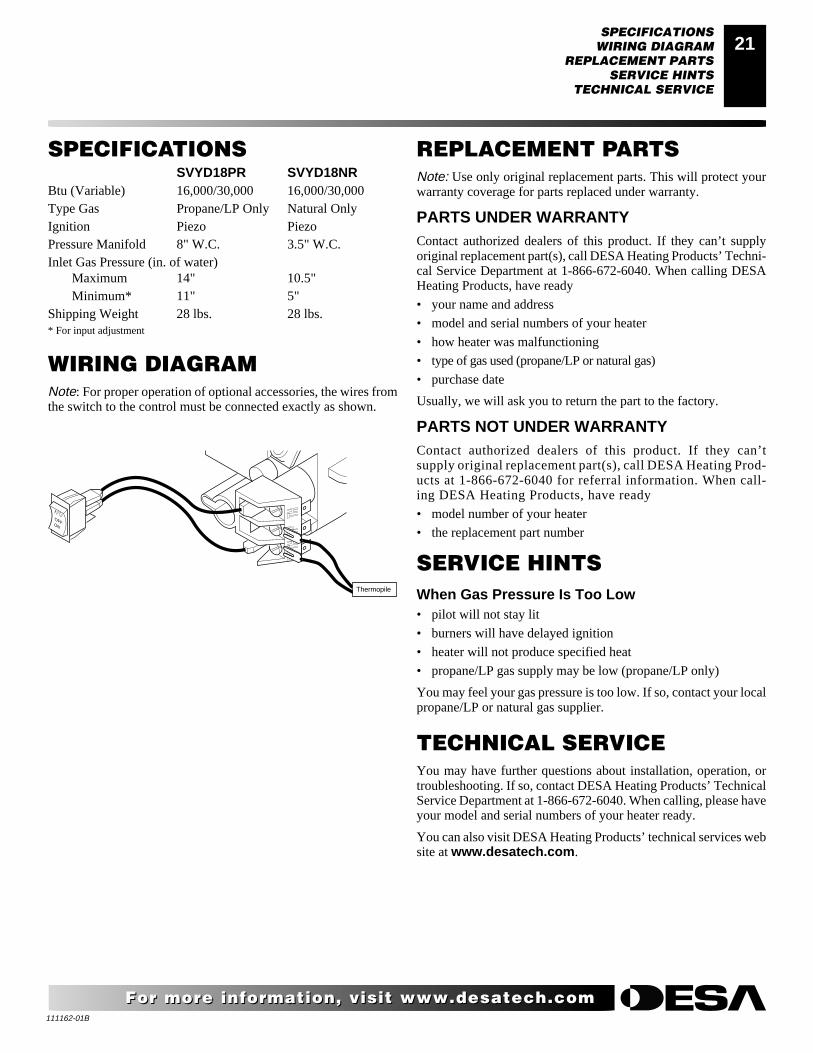
WIRING DIAGRAMNote: For proper operation of optional accessories, the wires fromthe switch to the control must be connected exactly as shown.
AUTOOFFON
Thermopile
SPECIFICATIONSWIRING DIAGRAM
REPLACEMENT PARTSSERVICE HINTS
TECHNICAL SERVICE
TECHNICAL SERVICEYou may have further questions about installation, operation, ortroubleshooting. If so, contact DESA Heating Products’ TechnicalService Department at 1-866-672-6040. When calling, please haveyour model and serial numbers of your heater ready.
You can also visit DESA Heating Products’ technical services website at www.desatech.com.
REPLACEMENT PARTSNote: Use only original replacement parts. This will protect yourwarranty coverage for parts replaced under warranty.
PARTS UNDER WARRANTYContact authorized dealers of this product. If they can’t supplyoriginal replacement part(s), call DESA Heating Products’ Techni-cal Service Department at 1-866-672-6040. When calling DESAHeating Products, have ready
• your name and address
• model and serial numbers of your heater
• how heater was malfunctioning
• type of gas used (propane/LP or natural gas)
• purchase date
Usually, we will ask you to return the part to the factory.
PARTS NOT UNDER WARRANTYContact authorized dealers of this product. If they can’tsupply original replacement part(s), call DESA Heating Prod-ucts at 1-866-672-6040 for referral information. When call-ing DESA Heating Products, have ready
• model number of your heater
• the replacement part number
SERVICE HINTSWhen Gas Pressure Is Too Low• pilot will not stay lit
• burners will have delayed ignition
• heater will not produce specified heat
• propane/LP gas supply may be low (propane/LP only)
You may feel your gas pressure is too low. If so, contact your localpropane/LP or natural gas supplier.
111162-01B
22
For more information, visit www.desatech.comFor more information, visit www.desatech.com
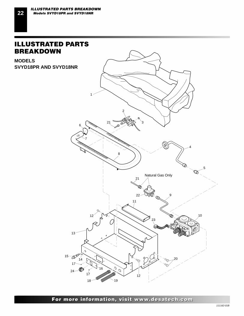
ILLUSTRATED PARTSBREAKDOWNMODELSSVYD18PR AND SVYD18NR
O
FF
P
ILOT
O
N
H
I
LO
H
I
LO
O
FF
P
ILOT
O
N
17
17
18 19
24
1514
16
13
12
12
11
22
23
20
10
9
21
4
8
5
3
2
21
7
6
1
Natural Gas Only
ILLUSTRATED PARTS BREAKDOWNModels SVYD18PR and SVYD18NR
111162-01B
2323
For more information, visit www.desatech.comFor more information, visit www.desatech.com
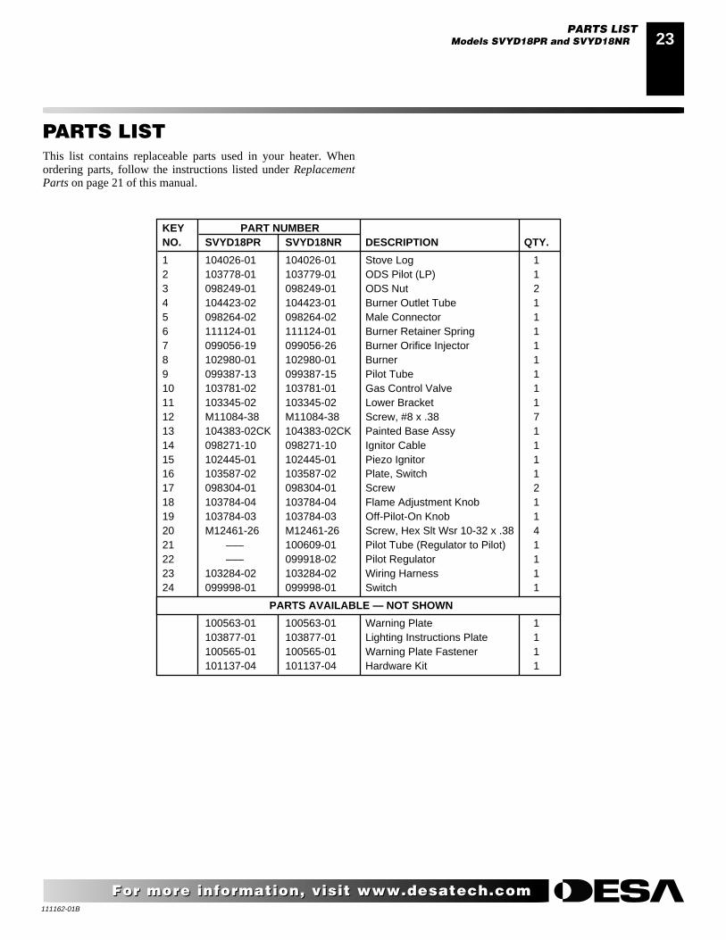
PARTS LISTThis list contains replaceable parts used in your heater. Whenordering parts, follow the instructions listed under ReplacementParts on page 21 of this manual.
KEY PART NUMBERNO. SVYD18PR SVYD18NR DESCRIPTION QTY.
1 104026-01 104026-01 Stove Log 12 103778-01 103779-01 ODS Pilot (LP) 13 098249-01 098249-01 ODS Nut 24 104423-02 104423-01 Burner Outlet Tube 15 098264-02 098264-02 Male Connector 16 111124-01 111124-01 Burner Retainer Spring 17 099056-19 099056-26 Burner Orifice Injector 18 102980-01 102980-01 Burner 19 099387-13 099387-15 Pilot Tube 110 103781-02 103781-01 Gas Control Valve 111 103345-02 103345-02 Lower Bracket 112 M11084-38 M11084-38 Screw, #8 x .38 713 104383-02CK 104383-02CK Painted Base Assy 114 098271-10 098271-10 Ignitor Cable 115 102445-01 102445-01 Piezo Ignitor 116 103587-02 103587-02 Plate, Switch 117 098304-01 098304-01 Screw 218 103784-04 103784-04 Flame Adjustment Knob 119 103784-03 103784-03 Off-Pilot-On Knob 120 M12461-26 M12461-26 Screw, Hex Slt Wsr 10-32 x .38 421 ––– 100609-01 Pilot Tube (Regulator to Pilot) 122 ––– 099918-02 Pilot Regulator 123 103284-02 103284-02 Wiring Harness 124 099998-01 099998-01 Switch 1
PARTS AVAILABLE — NOT SHOWN
100563-01 100563-01 Warning Plate 1103877-01 103877-01 Lighting Instructions Plate 1100565-01 100565-01 Warning Plate Fastener 1101137-04 101137-04 Hardware Kit 1
PARTS LISTModels SVYD18PR and SVYD18NR
111162-01B
24
For more information, visit www.desatech.comFor more information, visit www.desatech.com
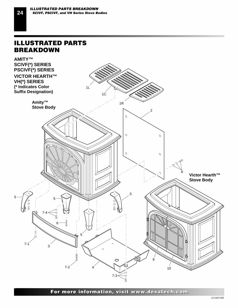
ILLUSTRATED PARTSBREAKDOWNAMITY™SCIVF(*) SERIESPSCIVF(*) SERIESVICTOR HEARTH™VH(*) SERIES(* Indicates ColorSuffix Designation)
ILLUSTRATED PARTS BREAKDOWNSCIVF, PSCIVF, and VH Series Stove Bodies
2
5
8
7-4
6
55
7-1
7-2
5
4
9
7-3
3
1R
1C
1L
10
Amity™Stove Body
Victor Hearth™Stove Body
111162-01B
2525
For more information, visit www.desatech.comFor more information, visit www.desatech.com
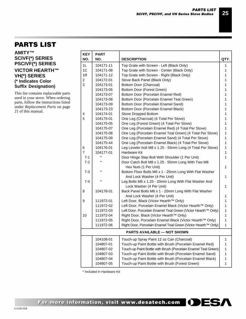
PARTS LISTAMITY™SCIVF(*) SERIESPSCIVF(*) SERIESVICTOR HEARTH™VH(*) SERIES(* Indicates ColorSuffix Designation)
This list contains replaceable partsused in your stove. When orderingparts, follow the instructions listedunder Replacement Parts on page21 of this manual.
KEY PARTNO. NO. DESCRIPTION QTY.
1L 104171-11 Top Grate with Screen - Left (Black Only) 11C 104171-08 Top Grate with Screen - Center (Black Only) 11R 104171-12 Top Grate with Screen - Right (Black Only) 12 104172-01 Stove Back Panel (Black Only) 13 104173-01 Bottom Door (Charcoal) 1
104173-05 Bottom Door (Forest Green) 1104173-07 Bottom Door (Porcelain Enamel Red) 1104173-08 Bottom Door (Porcelain Enamel Teal Green) 1104173-09 Bottom Door (Porcelain Enamel Sand) 1104173-23 Bottom Door (Porcelain Enamel Black) 1
4 104174-01 Stove Dropped Bottom 15 104175-01 One Leg (Charcoal) (4 Total Per Stove) 1
104175-05 One Leg (Forest Green) (4 Total Per Stove) 1104175-07 One Leg (Porcelain Enamel Red) (4 Total Per Stove) 1104175-08 One Leg (Porcelain Enamel Teal Green) (4 Total Per Stove) 1104175-09 One Leg (Porcelain Enamel Sand) (4 Total Per Stove) 1104175-44 One Leg (Porcelain Enamel Black) (4 Total Per Stove) 1
6 104176-01 Leg Leveler bolt M8 x 1.25 - 55mm Long (4 Total Per Stove) 17 104177-01 Hardware Kit 1 7-1 * Door Hinge Step Bolt With Shoulder (1 Per Unit) 1 7-2 * Door Catch Bolt M8 x 1.25 - 55mm Long With Two M8
Hex Nuts (1 Per Unit) 1 7-3 * Bottom Floor Bolts M6 x 1 - 25mm Long With Flat Washer
And Lock Washer (4 Per Unit) 1 7-4 * Leg Bolts M6 x 1.25 - 20mm Long With Flat Washer And
Lock Washer (4 Per Unit) 18 104178-01 Back Panel Bolts M6 x 1 - 20mm Long With Flat Washer
And Lock Washer (4 Per Unit) 19 111972-01 Left Door, Black (Victor Hearth™ Only) 1
111972-02 Left Door, Porcelain Enamel Black (Victor Hearth™ Only) 1111972-03 Left Door, Porcelain Enamel Teal Green (Victor Hearth™ Only) 1
10 111972-04 Right Door, Black (Victor Hearth™ Only) 1111972-05 Right Door, Porcelain Enamel Black (Victor Hearth™ Only) 1111972-06 Right Door, Porcelain Enamel Teal Green (Victor Hearth™ Only) 1
PARTS AVAILABLE — NOT SHOWN
104108-01 Touch-up Spray Paint 12 oz Can (Charcoal) 1104807-01 Touch-up Paint Bottle with Brush (Porcelain Enamel Red) 1104807-02 Touch-up Paint Bottle with Brush (Porcelain Enamel Teal Green) 1104807-03 Touch-up Paint Bottle with Brush (Porcelain Enamel Sand) 1104807-04 Touch-up Paint Bottle with Brush (Porcelain Enamel Black) 1104807-05 Touch-up Paint Bottle with Brush (Forest Green) 1
* Included In Hardware Kit
PARTS LISTSCIVF, PSCIVF, and VH Series Stove Bodies
111162-01B
26
For more information, visit www.desatech.comFor more information, visit www.desatech.com
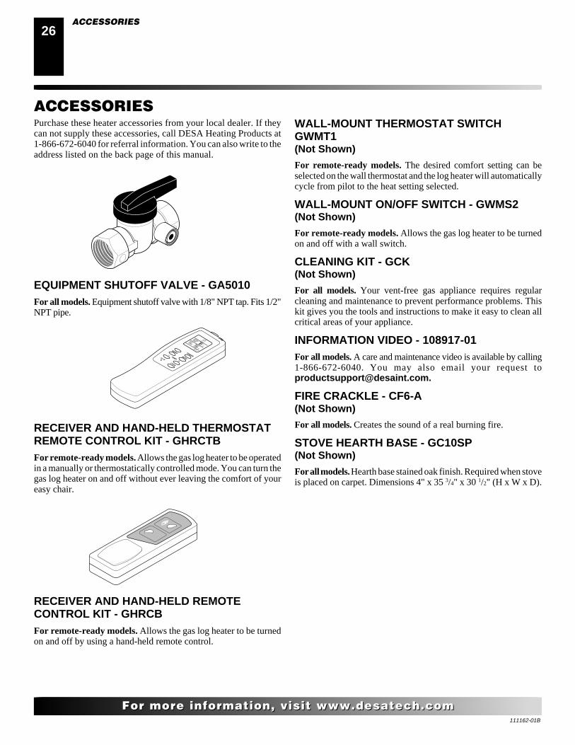
Purchase these heater accessories from your local dealer. If theycan not supply these accessories, call DESA Heating Products at1-866-672-6040 for referral information. You can also write to theaddress listed on the back page of this manual.
EQUIPMENT SHUTOFF VALVE - GA5010For all models. Equipment shutoff valve with 1/8" NPT tap. Fits 1/2"NPT pipe.
RECEIVER AND HAND-HELD THERMOSTATREMOTE CONTROL KIT - GHRCTBFor remote-ready models. Allows the gas log heater to be operatedin a manually or thermostatically controlled mode. You can turn thegas log heater on and off without ever leaving the comfort of youreasy chair.
RECEIVER AND HAND-HELD REMOTECONTROL KIT - GHRCBFor remote-ready models. Allows the gas log heater to be turnedon and off by using a hand-held remote control.
WALL-MOUNT THERMOSTAT SWITCHGWMT1(Not Shown)
For remote-ready models. The desired comfort setting can beselected on the wall thermostat and the log heater will automaticallycycle from pilot to the heat setting selected.
WALL-MOUNT ON/OFF SWITCH - GWMS2(Not Shown)
For remote-ready models. Allows the gas log heater to be turnedon and off with a wall switch.
CLEANING KIT - GCK(Not Shown)
For all models. Your vent-free gas appliance requires regularcleaning and maintenance to prevent performance problems. Thiskit gives you the tools and instructions to make it easy to clean allcritical areas of your appliance.
INFORMATION VIDEO - 108917-01For all models. A care and maintenance video is available by calling1-866-672-6040. You may also email your request [email protected].
FIRE CRACKLE - CF6-A(Not Shown)
For all models. Creates the sound of a real burning fire.
STOVE HEARTH BASE - GC10SP(Not Shown)
For all models. Hearth base stained oak finish. Required when stoveis placed on carpet. Dimensions 4" x 35 3/4" x 30 1/2" (H x W x D).
ACCESSORIES
ACCESSORIES
111162-01B
2727
For more information, visit www.desatech.comFor more information, visit www.desatech.com
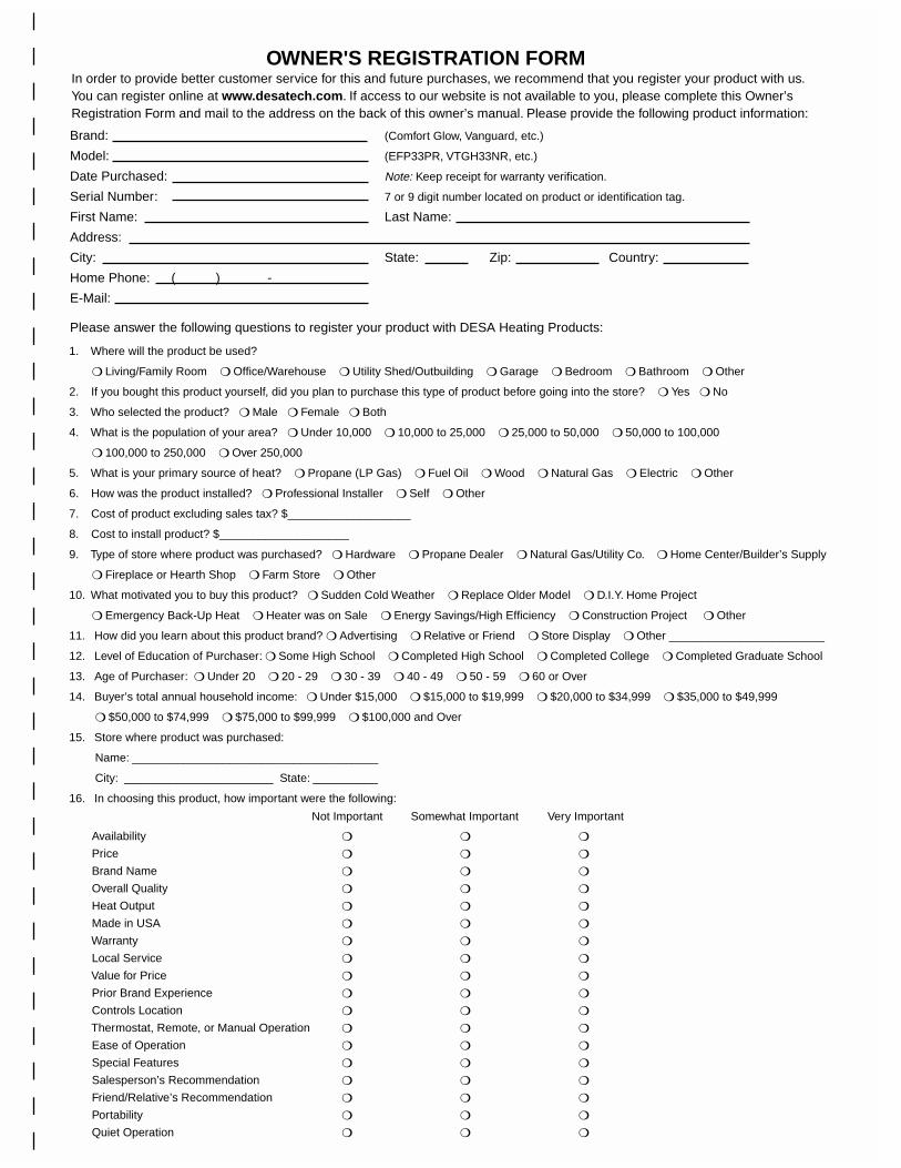
1. Where will the product be used?
❍ Living/Family Room ❍ Office/Warehouse ❍ Utility Shed/Outbuilding ❍ Garage ❍ Bedroom ❍ Bathroom ❍ Other
2. If you bought this product yourself, did you plan to purchase this type of product before going into the store? ❍ Yes ❍ No
3. Who selected the product? ❍ Male ❍ Female ❍ Both
4. What is the population of your area? ❍ Under 10,000 ❍ 10,000 to 25,000 ❍ 25,000 to 50,000 ❍ 50,000 to 100,000
❍ 100,000 to 250,000 ❍ Over 250,000
5. What is your primary source of heat? ❍ Propane (LP Gas) ❍ Fuel Oil ❍ Wood ❍ Natural Gas ❍ Electric ❍ Other
6. How was the product installed? ❍ Professional Installer ❍ Self ❍ Other
7. Cost of product excluding sales tax? $___________________
8. Cost to install product? $____________________
9. Type of store where product was purchased? ❍ Hardware ❍ Propane Dealer ❍ Natural Gas/Utility Co. ❍ Home Center/Builder’s Supply
❍ Fireplace or Hearth Shop ❍ Farm Store ❍ Other
10. What motivated you to buy this product? ❍ Sudden Cold Weather ❍ Replace Older Model ❍ D.I.Y. Home Project
❍ Emergency Back-Up Heat ❍ Heater was on Sale ❍ Energy Savings/High Efficiency ❍ Construction Project ❍ Other
11. How did you learn about this product brand? ❍ Advertising ❍ Relative or Friend ❍ Store Display ❍ Other ________________________
12. Level of Education of Purchaser: ❍ Some High School ❍ Completed High School ❍ Completed College ❍ Completed Graduate School
13. Age of Purchaser: ❍ Under 20 ❍ 20 - 29 ❍ 30 - 39 ❍ 40 - 49 ❍ 50 - 59 ❍ 60 or Over
14. Buyer’s total annual household income: ❍ Under $15,000 ❍ $15,000 to $19,999 ❍ $20,000 to $34,999 ❍ $35,000 to $49,999
❍ $50,000 to $74,999 ❍ $75,000 to $99,999 ❍ $100,000 and Over
15. Store where product was purchased:
Name: ______________________________________
City: _______________________ State: __________
16. In choosing this product, how important were the following:
Availability
Price
Brand Name
Overall Quality
Heat Output
Made in USA
Warranty
Local Service
Value for Price
Prior Brand Experience
Controls Location
Thermostat, Remote, or Manual Operation
Ease of Operation
Special Features
Salesperson’s Recommendation
Friend/Relative’s Recommendation
Portability
Quiet Operation
OWNER'S REGISTRATION FORM
Please answer the following questions to register your product with DESA Heating Products:
In order to provide better customer service for this and future purchases, we recommend that you register your product with us. You can register online at www.desatech.com. If access to our website is not available to you, please complete this Owner’sRegistration Form and mail to the address on the back of this owner’s manual. Please provide the following product information:
Not Important Somewhat Important Very Important
❍
❍
❍
❍
❍
❍
❍
❍
❍
❍
❍
❍
❍
❍
❍
❍
❍
❍
❍
❍
❍
❍
❍
❍
❍
❍
❍
❍
❍
❍
❍
❍
❍
❍
❍
❍
❍
❍
❍
❍
❍
❍
❍
❍
❍
❍
❍
❍
❍
❍
❍
❍
❍
❍
Brand: (Comfort Glow, Vanguard, etc.)
Model: (EFP33PR, VTGH33NR, etc.)
Date Purchased: Note: Keep receipt for warranty verification.
Serial Number: 7 or 9 digit number located on product or identification tag.
First Name: Last Name:
Address:
City: State: Zip: Country:
Home Phone: ( ) -
E-Mail:

111162-01B
28
For more information, visit www.desatech.comFor more information, visit www.desatech.com
2701 Industrial DriveP.O. Box 90004Bowling Green, KY 42102-9004
PostageRequired
TAPETAPE

111162-01B
2929
For more information, visit www.desatech.comFor more information, visit www.desatech.com
NOTES_______________________________________________________________________________________________
_______________________________________________________________________________________________
_______________________________________________________________________________________________
_______________________________________________________________________________________________
_______________________________________________________________________________________________
_______________________________________________________________________________________________
_______________________________________________________________________________________________
_______________________________________________________________________________________________
_______________________________________________________________________________________________
_______________________________________________________________________________________________
_______________________________________________________________________________________________
_______________________________________________________________________________________________
_______________________________________________________________________________________________
_______________________________________________________________________________________________
_______________________________________________________________________________________________
_______________________________________________________________________________________________
_______________________________________________________________________________________________
_______________________________________________________________________________________________
_______________________________________________________________________________________________
_______________________________________________________________________________________________
_______________________________________________________________________________________________
_______________________________________________________________________________________________
_______________________________________________________________________________________________
_______________________________________________________________________________________________
_______________________________________________________________________________________________
_______________________________________________________________________________________________
_______________________________________________________________________________________________
_______________________________________________________________________________________________
_______________________________________________________________________________________________
_______________________________________________________________________________________________
_______________________________________________________________________________________________
_______________________________________________________________________________________________
_______________________________________________________________________________________________
_______________________________________________________________________________________________
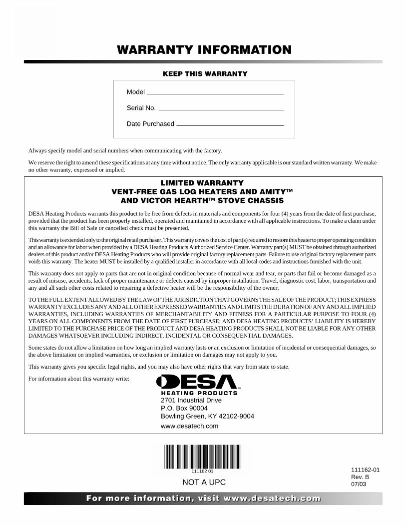
111162-01B
30
For more information, visit www.desatech.comFor more information, visit www.desatech.com
LIMITED WARRANTYVENT-FREE GAS LOG HEATERS AND AMITY™
AND VICTOR HEARTH™ STOVE CHASSIS
DESA Heating Products warrants this product to be free from defects in materials and components for four (4) years from the date of first purchase,provided that the product has been properly installed, operated and maintained in accordance with all applicable instructions. To make a claim underthis warranty the Bill of Sale or cancelled check must be presented.
This warranty is extended only to the original retail purchaser. This warranty covers the cost of part(s) required to restore this heater to proper operating conditionand an allowance for labor when provided by a DESA Heating Products Authorized Service Center. Warranty part(s) MUST be obtained through authorizeddealers of this product and/or DESA Heating Products who will provide original factory replacement parts. Failure to use original factory replacement partsvoids this warranty. The heater MUST be installed by a qualified installer in accordance with all local codes and instructions furnished with the unit.
This warranty does not apply to parts that are not in original condition because of normal wear and tear, or parts that fail or become damaged as aresult of misuse, accidents, lack of proper maintenance or defects caused by improper installation. Travel, diagnostic cost, labor, transportation andany and all such other costs related to repairing a defective heater will be the responsibility of the owner.
TO THE FULL EXTENT ALLOWED BY THE LAW OF THE JURISDICTION THAT GOVERNS THE SALE OF THE PRODUCT; THIS EXPRESSWARRANTY EXCLUDES ANY AND ALL OTHER EXPRESSED WARRANTIES AND LIMITS THE DURATION OF ANY AND ALL IMPLIEDWARRANTIES, INCLUDING WARRANTIES OF MERCHANTABILITY AND FITNESS FOR A PARTICULAR PURPOSE TO FOUR (4)YEARS ON ALL COMPONENTS FROM THE DATE OF FIRST PURCHASE; AND DESA HEATING PRODUCTS’ LIABILITY IS HEREBYLIMITED TO THE PURCHASE PRICE OF THE PRODUCT AND DESA HEATING PRODUCTS SHALL NOT BE LIABLE FOR ANY OTHERDAMAGES WHATSOEVER INCLUDING INDIRECT, INCIDENTAL OR CONSEQUENTIAL DAMAGES.
Some states do not allow a limitation on how long an implied warranty lasts or an exclusion or limitation of incidental or consequential damages, sothe above limitation on implied warranties, or exclusion or limitation on damages may not apply to you.
This warranty gives you specific legal rights, and you may also have other rights that vary from state to state.
For information about this warranty write:
2701 Industrial DriveP.O. Box 90004Bowling Green, KY 42102-9004
www.desatech.com
KEEP THIS WARRANTY
WARRANTY INFORMATION
Model
Serial No.
Date Purchased
111162-01Rev. B07/03
Always specify model and serial numbers when communicating with the factory.
We reserve the right to amend these specifications at any time without notice. The only warranty applicable is our standard written warranty. We makeno other warranty, expressed or implied.
NOT A UPC
111162 01