Embed Size (px)
Citation preview
Duty Cycle Graph
CSA Certified Duty Cycle Graph Duty Cycle Graph
50°F10°C
75°F24°C
100°F38°C
125°F52°C
150°F65°C
25%
50%
75%
100%
On/Off/Jog
Ambient Temperature Ambient Temperature
CSA Certified Duty Cycle Graph
50°F10°C
75°F24°C
100°F38°C
125°F52°C
150°F65°C
25%
50%
75%
100%
On/Off/Jog
Duty Cycle Graph
50°F10°C
75°F24°C
100°F38°C
125°F52°C
150°F65°C
25%
50%
75%
100%
On/Off/Jog
Proportional
Ambient Temperature
50°F10°C
75°F24°C
100°F38°C
125°F52°C
150°F65°C
25%
50%
75%
100%
On/Off/Jog
Proportional
Ambient Temperature
CSA Certified Duty Cycle Graph
50°F10°C
75°F24°C
100°F38°C
125°F52°C
150°F65°C
On/Off/Jog / Proportional On/Off/Jog / Proportional
Ambient Temperature
50°F10°C
75°F24°C
100°F38°C
125°F52°C
25%
50%
75%
100%
Ambient Temperature
• Duty cycle is defi ned as the ratio of total time vs. run time, and is a function of environmental conditions including ambient temperature, supply voltage and control signal stability
• Duty Cycle rating on all proportional control actuators is managed (75% maximum).
Duty cycle graph
238703C US
®
SD
15_P213_H
V Ver N
_100915
Page 1 of 4 P2/3 HV Series
Note: Not all combinations are possible. Please consult factory.
On/Off
P
800”lbs / 90Nm
1335”lbs / 150Nm
Non-SpringReturn
120
230
2
3
NNEMA
4X
4
120VAC+10%
230VAC+10%
P 2 - 120 P N 4Product Family Control Options Special DesignationsVoltage Options
RO Relay Open (2 pos)
RC Relay Close (2 pos)
TS
ED
68
Torque Switch
Extended Duty
IP68
PremiumProportional
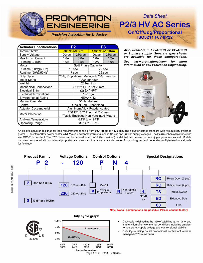
An electric actuator designed for load requirements ranging from 800”lbs up to 1335”lbs. The actuator comes standard with two auxiliary switches (Form C), an internal low power heater, a NEMA 4X environmental rating, and in 120vac and 230vac supply voltages. The P2/3 mechanical connections are ISO5211 compliant. The P2/3 Series can be ordered as an on/off (two position) model that can be used in bump/jog applications as well. Models can also be ordered with an internal proportional control card that accepts a wide range of control signals and generates multiple feedback signals for field use.
Data Sheet
P2/3 HV AC SeriesOn/Off/Jog/Proportional
ISO5211 F07 8P22
Also available in 12VAC/DC or 24VAC/DC or 3 phase supply. Separate spec sheets are available for these configurations.See www.promationei.com for more information or call ProMation Engineering.
P2/3 SD
Actuator Specifi cations P2 P3Torque “lb/Nm 800”lbs/90Nm 1335”lbs/150NmSupply Voltage 120vac 230vac 120vac 230vacMax Inrush Current 1.8A 0.8A 1.8A 1.2ARunning Current 1.0A 0.5A 1.2A 1.0AMotor Split Phase CapacitorRuntime (90°@60Hz) 15 sec 22 secRuntime (90O@50Hz) 17 sec 26 secDuty Cycle 25%, Proportional: Managed (75% maximum)Motor Starts 1200 per hourWeight 26lbs/12kgMechanical Connections ISO5211 F07 8pt 22mmElectrical Entry (2) 3/4” NPTElectrical Terminations 12-16gaEnvironmental Rating NEMA 4/4XManual Override 5” HandwheelControl On/Off-Jog, ProportionalActuator Case material Aluminum Alloy, Powder coated
Motor Protection 230°F/110°C Thermal F* Class*Totally Enclosed Non-Ventilated Motors
Ambient Temperature Operating Range
-22°F to +125°F-30°C to +52°C
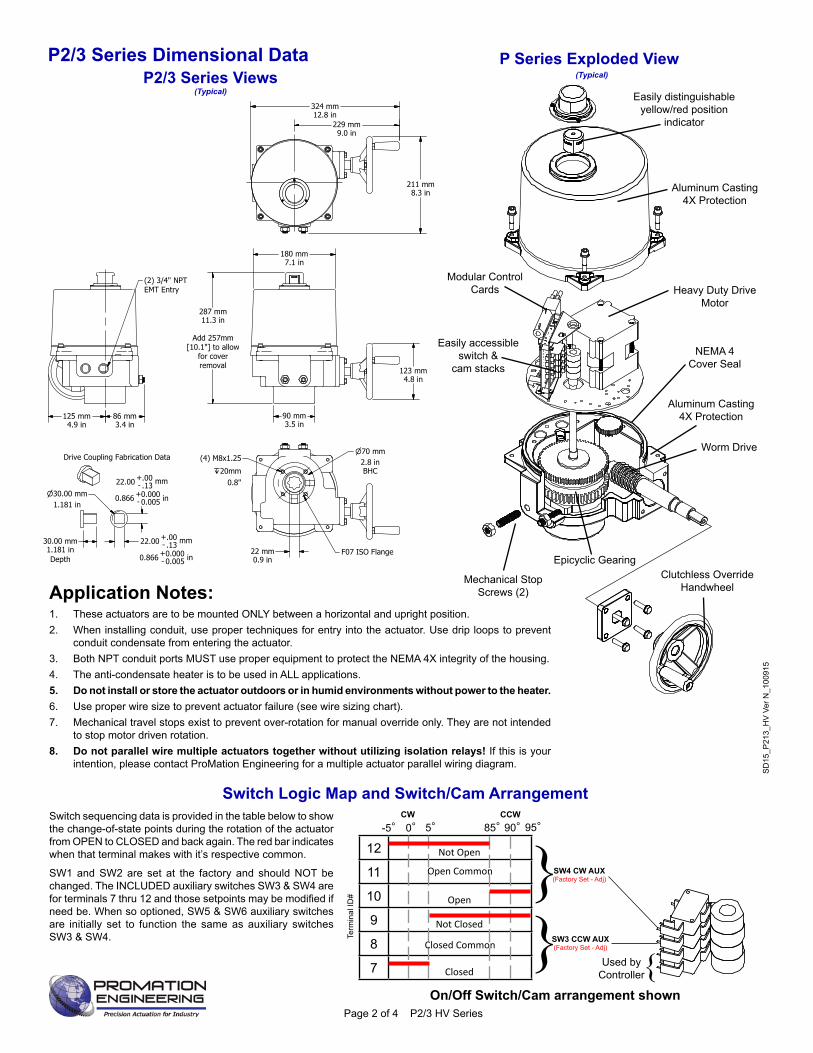
P Series Exploded View
Easily distinguishable yellow/red position
indicator
Worm Drive
Heavy Duty Drive Motor
Easily accessible switch &
cam stacks
Modular ControlCards
Clutchless OverrideHandwheel
Aluminum Casting4X Protection
Mechanical Stop Screws (2)
Epicyclic Gearing
Aluminum Casting4X Protection
NEMA 4Cover Seal
(Typical)
Application Notes:1. These actuators are to be mounted ONLY between a horizontal and upright position.2. When installing conduit, use proper techniques for entry into the actuator. Use drip loops to prevent
conduit condensate from entering the actuator. 3. Both NPT conduit ports MUST use proper equipment to protect the NEMA 4X integrity of the housing. 4. The anti-condensate heater is to be used in ALL applications. 5. Do not install or store the actuator outdoors or in humid environments without power to the heater.6. Use proper wire size to prevent actuator failure (see wire sizing chart). 7. Mechanical travel stops exist to prevent over-rotation for manual override only. They are not intended
to stop motor driven rotation.8. Do not parallel wire multiple actuators together without utilizing isolation relays! If this is your
intention, please contact ProMation Engineering for a multiple actuator parallel wiring diagram.
Switch Logic Map and Switch/Cam Arrangement
Term
inal
ID#
12
11
10
9
8
7
-5° 0°CW CCW
85°5° 90° 95°
SW3 CCW AUX(Factory Set - Adj)
SW4 CW AUX(Factory Set - Adj)}
}Closed Common
Open Common
}Used by Controller
Open
Not Closed
Closed
Not Open
Switch sequencing data is provided in the table below to show the change-of-state points during the rotation of the actuator from OPEN to CLOSED and back again. The red bar indicates when that terminal makes with it’s respective common.
SW1 and SW2 are set at the factory and should NOT be changed. The INCLUDED auxiliary switches SW3 & SW4 are for terminals 7 thru 12 and those setpoints may be modifi ed if need be. When so optioned, SW5 & SW6 auxiliary switches are initially set to function the same as auxiliary switches SW3 & SW4.
On/Off Switch/Cam arrangement shown
SD
15_P
213_
HV
Ver
N_1
0091
5
Page 2 of 4 P2/3 HV Series
P2/3 Series Dimensional Data1
1
2
2
A A
B B
Drawn By
Finish
Promation Engineering Inc.16138 Flight Path Drive
Brooksville, Fl 34604Phone: 352-544-8436Fax: 352-544-8439
This Document is the property of ProMation Engineering,Inc. Distribution of this document without the written
consent of the owner is Strictly forbidden. Failure to comply will incur a liability for Damages.
Checked By4/8/2015
P2~P3 Dim Data Rev.
G
NO SCALE Sheet Number: 1
Material
ProMation Engineering, Inc.KHL
KHL
4/25/2013
P2_3 F07 8P22 DimData.idw
Created:
Last Checked:
Part No.
Dwg. Name
Dimensional Data for P2~P3 Actuators
Engineering Change NoticeChange Date Description Name
04.25.13 Document transferred to Inventor format KHL
11.12.13 Added rounded edges on Drive Coupling Data KHL
04.15.2014 Added tolerance on drive coupling data KHL
10.07.2014 Pushed square dimension to three decimal places KHL
REV
A
B
C
D
E
F
Dimensional Tolerances (Unless Otherwise Noted):X ± 2.5mm [X.X ± .1]
X.X ± .3mm [X.XX ± .01"]X.XX ± .13mm [X.XXX ± .005"]
ALL TOLERANCE FEATURES IN mm
G 04.08.2015 Added Isometric view of Drive Coupling and "Depth" tag for clarity KHL
H
Drive Coupling Fabrication Data
22.00 - .13.00+ mm
0.866 - 0.0050.000+ in
22.00 - .13.00+ mm
0.866 - 0.0050.000+ in
30.00 mm1.181 inDepth
30.00 mm1.181 in
229 mm9.0 in
324 mm12.8 in
211 mm8.3 in
123 mm4.8 in
180 mm7.1 in
90 mm3.5 in
287 mm11.3 in
Add 257mm
[10.1"] to allowfor coverremoval
70 mm2.8 inBHC
22 mm0.9 in
(4) M8x1.25
20mm0.8"
F07 ISO Flange
(2) 3/4" NPTEMT Entry
125 mm4.9 in
86 mm3.4 in
P2/3 Series Views(Typical)
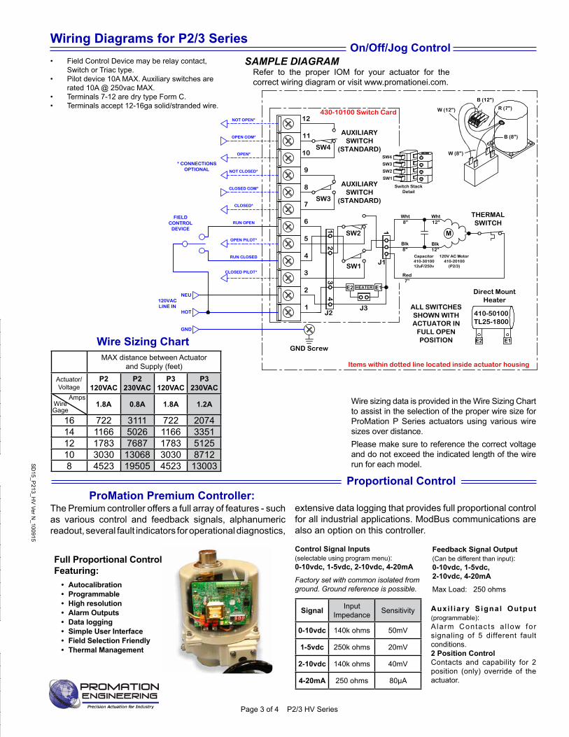
On/Off/Jog Control• Field Control Device may be relay contact,
Switch or Triac type. • Pilot device 10A MAX. Auxiliary switches are
rated 10A @ 250vac MAX. • Terminals 7-12 are dry type Form C. • Terminals accept 12-16ga solid/stranded wire.
Control Signal Inputs(selectable using program menu):0-10vdc, 1-5vdc, 2-10vdc, 4-20mA
Factory set with common isolated from ground. Ground reference is possible.
Signal Input Impedance Sensitivity
0-10vdc 140k ohms 50mV
1-5vdc 250k ohms 20mV
2-10vdc 140k ohms 40mV
4-20mA 250 ohms 80µA
Feedback Signal Output(Can be different than input):0-10vdc, 1-5vdc, 2-10vdc, 4-20mA
Max Load: 250 ohms
extensive data logging that provides full proportional control for all industrial applications. ModBus communications are also an option on this controller.
Full Proportional Control Featuring:
• Autocalibration• Programmable• High resolution• Alarm Outputs• Data logging• Simple User Interface• Field Selection Friendly• Thermal Management
Auxi l iary Signal Output(programmable):A larm Contacts a l low for signaling of 5 different fault conditions. 2 Position ControlContacts and capability for 2 position (only) override of the actuator.
Proportional Control
The Premium controller offers a full array of features - such as various control and feedback signals, alphanumeric readout, several fault indicators for operational diagnostics,
ProMation Premium Controller:
SAMPLE DIAGRAMRefer to the proper IOM for your actuator for the correct wiring diagram or visit www.promationei.com.
Wire sizing data is provided in the Wire Sizing Chart to assist in the selection of the proper wire size for ProMation P Series actuators using various wire sizes over distance. Please make sure to reference the correct voltage and do not exceed the indicated length of the wire run for each model.S
D15_P
213_HV
Ver N_100915
Page 3 of 4 P2/3 HV Series
P2/3 SD WD
Wire Sizing ChartMAX distance between Actuator
and Supply (feet)
Actuator/Voltage
P2120VAC
P2230VAC
P3120VAC
P3230VAC
1.8A 0.8A 1.8A 1.2A
16 722 3111 722 207414 1166 5026 1166 335112 1783 7687 1783 512510 3030 13068 3030 87128 4523 19505 4523 13003
WireGage
Amps
MAX distance between Actuator and Supply (feet)
Actuator P4 P5 P6Voltage 120VAC 230VAC 120VAC 230VAC 120VAC 230VAC
3.8A 2.0A 3.8A 2.0A 3.8A 2.0A
18 217 792 217 792 217 79216 342 1245 342 1245 342 124514 552 2010 552 2010 552 201012 844 3075 844 3075 844 307510 1435 5227 1435 5227 1435 52278 2142 7802 2142 7802 2142 7802
MAX distance between Actuator and Supply (feet)
Actuator P2 P3Voltage 120VAC 230VAC 120VAC 230VAC
1.8A 0.8A 1.8A 1.2A
18 459 1980 459 132016 722 3111 722 207414 1166 5026 1166 335112 1783 7687 1783 512510 3030 13068 3030 87128 4523 19505 4523 13003
MAX distance between Actuator and Supply (feet)
Actuator P7 P8Voltage 120VAC 230VAC 120VAC 230VAC
8.5A 4.1A 9.0A 4.4A
18 - 386 - 36016 - 607 - 56614 247 981 233 91412 377 1500 357 139810 642 2550 606 23768 958 3806 905 3546
MAX distance between Actuator and Supply (feet)
Actuator P9 P10Voltage 120VAC 230VAC 120VAC 230VAC
5.8A 3.8A 6.5A 4.0A
18 - 417 - 39616 - 655 - 62214 362 1058 323 100512 553 1618 494 153710 940 2751 839 26148 1404 4106 1252 3901
MAX distance between Actuator and Supply (feet)
Actuator P11 P12Voltage 120VAC 230VAC 120VAC 230VAC
7.0A 4.2A 8.0A 4.4A
18 - 377 - 36016 - 593 - 56614 300 957 262 91412 458 1464 401 139810 779 2489 682 23768 1163 3715 1018 3546
12
11
10
9
8
7
GND Screw
M
SW3
SW4
THERMALSWITCH
AUXILIARYSWITCH
(STANDARD)
ALL SWITCHESSHOWN WITHACTUATOR IN
FULL OPENPOSITION
AUXILIARYSWITCH
(STANDARD)
Red7"
Direct MountHeater
Blk8"
Wht8"
Wht12"
Blk12"
E1E2
Actuator ships in fully closed position!
410-50100TL25-1800
Capacitor410-3010012uF/250v
6
5
4
3
2
1
J1
HEATER
SW2
SW1
J2
E1E2
J3
112
43
Items within dotted line located inside actuator housing
430-10100 Switch Card
SW1
SW2
SW3
SW4
Switch StackDetail
NOT OPEN*
OPEN COM*
OPEN*
NOT CLOSED*
CLOSED COM*
CLOSED*
RUN OPEN
OPEN PILOT*
RUN CLOSED
CLOSED PILOT*
NEU
HOT
120VACLINE IN
* CONNECTIONSOPTIONAL
FIELDCONTROL
DEVICE
GND
120V AC Motor410-20100
(P2/3)
R (7")W (12")
B (12")
B (8")
W (8")
1
AW
D-8
50
-24
10
0
Use For:
P2/3-120N4-AC
Wiring Diagrams for P2/3 Series
Use your smart phone barcode scanner app here.
16138 Flight Path Drive Brooksville, FL 34604
Phone (352) 544-8436 Fax (352) 544-8439email: [email protected]
ProMation Engineering follows a policy of continual product updates and enhancements. Our website is the best place to obtain the latest product documentation, including the wiring diagrams for these controllers. Visit us at www.promationei.com or use the QR code below to link to the site.
PL SeriesLinear Drive
Up to 4400lbs down/up force and up to 100mm
(4”) stem travelFor globe valves, gate valves and linear travel devices. With override handwheel. Available with On/Off/Jog or Proportional
control for 24vac, 24vdc, 120vac & 230vac supplies.
P SeriesNon-Spring Return
55”lbs through 40,000”lbs.Quarter-Turn,
with Manual OverrideAvailable with On/Off/Jog or
Proportional control. For 12vac/dc, 24vac/dc, 120vac, 230vac, 230v/3 phase, 380v/3 phase &
460v/3phase supplies.
PA~PD Series Spring Return
445”lbs through 2300”lbs.Quarter-Turn, both with and w/o
manual override handwheel. Spring either CW or CCW.
Available with On/Off control for 24vac/dc and On/Off or
Proportional control for 120vac & 230vac supplies. Stepdown
for 3phase available.
PBU Battery Back-Up Systems
Provides powersuffi cient to drive P Series actuators
to fi eld-selectable fail-safe positions. For P Series & PL
Series actuators in On/Off and Proportional control modes.Available for 24/120/230vac
actuators. 120vac/230 vac supply.
ProMation Product Line
• Premium Proportional Controller Option. Converts 2 position to proportional control.
• Extended Duty Motor - 75% Duty Cycle.• Single Wire Control Relay (Internal) Units operate
NORMALLY CLOSED - ENERGIZE TO OPEN.• Single Wire Control Relay (Internal) Units operate
NORMALLY OPEN- ENERGIZE TO CLOSED.
• Mechanical Torque Switch Assembly. P2~P13 except P2/3 120/230PN4-AC series.
• IP68 Protection, tested to 0.7kgf/cm2 for 72 hours. P2~P8 only.• 0-45-90 degree rotation option. • 0-90-180 degree rotation option. P2~P8 only.• 0-180 degree rotation option. No Mid-point position is offered.
(On/Off only). P2~P8 only.• 1k ohm position feedback potentiometer.• 5k ohm position feedback potentiometer.• 10k ohm position feedback potentiometer.• 4-20mA feedback generator for On/Off/Jog actuators.• Auxiliary Switch set. Provides 3rd and 4th auxiliary switches
(Form C x 2).• Adjustable Timer, Dual Set Point Timer (Duration and
Frequency) (Contact factory for application assistance).
• Proportional Control Signal override capability (OPEN OR CLOSED). P2~P13 Series only.
• Integral Thermostat for Heater Control - turns on at 32°F, turns off at 50°F.
• Cold weather auxiliary heater option. Thermostatically controlled, On 32°F, Off at 50°F, auto reset, hermetically sealed, 120/230vac On/Off/Jog type actuators. 175W Internal Heater, 2A power consumption.
• Timer function which slows actuator rotation (cycle time) using an internally mounted octal timer. (Contact factory for application assistance). P2 - P13 series only.
• Chain wheel override for applications where an actuator is mounted some distance from the fl oor. (Use with LCS).
• Local Control Stations (LCS) ProMation LCSs are designed to be remotely located or directly mounted to the actuator. Proportional actuators will have different options than On/Off. Available in steel, stainless, or fi berglass enclosures.(See catalog for additional Local Control Selections).
• 3 Phase models with or without Motor Control Center.
• Optional SCADA and Modbus compatability.
• Epoxy coating for increased environmental protection.
• Nylon coating for increased environmental protection.
• Stainless Steel enclosure. P1~P6 Only.
AVAILABLE OPTIONS (Factory Installed)
SD
15_P
213_
HV
Ver
N_1
0091
5
Page 4 of 4 P2/3 HV Series


![Guideline Report Writing RP2[1]](https://img.pdfslide.net/doc/110x75/577ccd751a28ab9e788c6cd3/guideline-report-writing-rp21.jpg)
![RP2 Leaflet v3(inside) DL 6pp - C-Fold[1]](https://img.pdfslide.net/doc/110x75/587883bd1a28ab466c8b687f/rp2-leaflet-v3inside-dl-6pp-c-fold1.jpg)