Embed Size (px)
Citation preview
8/2/2019 Paper on AXI
http://slidepdf.com/reader/full/paper-on-axi 1/5
D E SI G N S T R A T EG I E S A N D M E T H O D O L O G I E S
Volume 4, Number 1, 2005Information Quarterly [58]
Designing with the
AMBA™
3 AXI™
ProtocolT
Author: Mick Posner, Product Marketing Manager and Darrin Mossor,Corporate Applications Engineer,Synopsys Inc.
Synopsis: The need for higher performance applications is driving the requirement for a new age of on-chip communication infrastructure. Increasing the clock frequency no longer addresses this higher performance requirement, as the bottleneck is inherent in the existing bus infrastructure.
This paper examines the advantages of the new AMBA™ 3 AXI™ protocol for on-chip bus infrastructure, and how it revolutionizes the future of high performance SoC interconnect. It describes the AMBA 3 AXI protocol feature set that makes it suitable for the new high performance, low latency and low power designs. It also examines the verification tools and IP necessary to successfully complete design and verif ication in today’s reduced development design cycle.
he Re duc i ng De ve l opm e nt Cyc l e
As design complexity continues to
increase, time-to-market pressures force
shorter an d sh orter design cycles. High
performa nce designs a re techn ica lly com-
plex a nd requ ire va st am oun ts of verifica-
tion to ensure correct operation.
Interconnect topologies with multiple
address, data, handshaking buses and
transaction cycles that complete out of order over many cycles enable high per-
formance and low latency, but can no
longer be verified with the standa rd direct-
ed testing methodologies. These features
on th eir own not on ly take the verification
task to the next level of complexity, but
also introduce corner cases that must be
captured and tested. Unfortunately these
corner cases are typically very hard to
identify a nd, if missed, could m ean failure
of the resulting design.
Stan dar ds an d Re use
One way to reduce the risk and pressuresof a n ew design is through th e use of stan-
dards and reuse. Today, designers can also
choose from a ran ge of open specifications
of on-chip interface protocols. Choosing
this option facilitates use of proven, pre-
designed, pre-verified IP and verification
components. With more proven IP in the
design, and by the deployment of
Verification IP (VIP), design ers can focus
on differentiating th eir design rath er tha n
verification of the standard based proto-
col.
Use of existing standard protocol IP and
VIP shortens subsystem creation time, as
less effort a nd time is required to build a nd
verify the SoC infrastructure. The use of
these standards-based protocols also aids
interoperability, as all components will
ha ve been designed to th e sam e specifica-
tion. This dra ma tically reduces the overall
risk associated with the design.
The AMBA 3 protocol fam ily defines a n ew
set of on-chip interface protocols for SoC
designs. These are the latest generation
protocols, which are interoperable with
existing bus technology defined in the
AMBA 2 specification. The AMBA 3 AXI
protocol is an advanced microprocessor
system bus interface which is part of this
new protocol family.
The AMBA 3 AXI protocol specification is
openly a vailable for download from ARM
and is well supported and documented.This open access, coupled with the
advanced features that AMBA 3 AXI pro-
vides, ma kes it a good can didate to be the
de-facto standard for the next generation
of on-chip bus interconnects.
Design Veri f icat ion Considerations
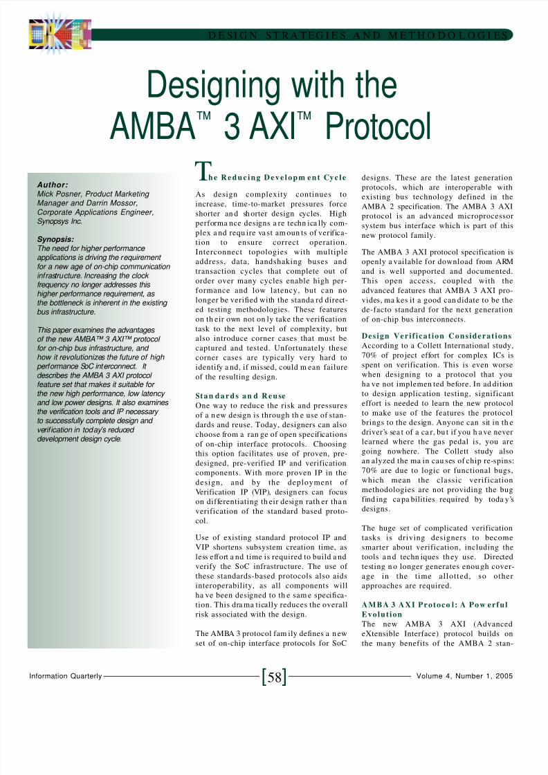
According to a Collett International study,
70% of pro ject effort for com plex ICs is
spent on verification. This is even worse
when designing to a protocol that you
ha ve not implemen ted before. In ad dition
to design application testing, significant
effort is needed to learn the new protocol
to make use of the features the protocol
brings to the design. Anyone can sit in th e
driver’s sea t of a ca r, bu t if you h a ve never
learned where the gas pedal is, you are
going nowhere. The Collett study also
an alyzed the ma in cau ses of chip re-spins
70% are due to logic or functional bugs,
which mean the classic verification
methodologies are not providing the bug
find ing ca pa bilities required by toda y’s
designs.
The huge set of complicated verification
tasks is driving designers to become
smarter about verification, including the
tools a n d techn iques th ey use. Directed
testing n o longer generates enou gh cover-
age in the time allotted, so other
approaches are required.
AMBA 3 AXI Protoco l : A Pow erful
Evolution
The new AMBA 3 AXI (Advanced
eXtensible Interface) protocol builds on
the many benefits of the AMBA 2 stan-
8/2/2019 Paper on AXI
http://slidepdf.com/reader/full/paper-on-axi 2/5
Feat ures of t he AMBA 3 AXI prot ocol
include:
• Separate a ddress/control and da ta
phases
• Support for una ligned data transfers
using byte strobes
• Burst-ba sed tran sactions with only start
a ddress issued
• Separate read an d write data cha nnels
to en a ble low-cost Direct Mem ory Access
(DMA)
• Ability to issue multiple outstan ding
addresses
• Out-of-order tran saction completion
• Ea sy addition of register stages to
provide timing closure
• Protocol includes optiona l extensions
that cover signaling for low-power
operation
Advantages of the AMBA 3 AXI proto-
col include:• Independently a cknowledged address &
data chan nels
• Out of order comp letion of bursts
• Exclusive access (atom ic tran saction)
• System level cache support
• Access security support
Fe atur e Com pa r ison:
AMBA 2 AHB™ Protocol Versus
AMBA 3 AXI Protocol
AMBA 3 AXI Protoco l : Cha nn el
P o w e r
The AMBA 3 AXI a rchitectu re differs sig-
nificantly from previous AMBA protocols
by the introduction of cha nn els.
Each of the five independent channels
consists of a set of informa tion signa ls an d
uses a two-wa y VALID an d READY h a n d-
D E SI G N S T R A TEG I E S A N D M E T H O D O L O G I E S
Volume 4, Number 1, 2005Information Quarterly [59]
dard by greatly extending the perform-
ance and flexibility of the systems based
on AMBA technology. Based on the indus-
try’s needs, and created in collaboration
with more than 30 companies, the AMBA
3 AXI protocol is available now and
a ddresses the n eeds of the coming gen era-
tion of designs.
The AMBA 3 AXI protocol defines a un idi-
rectional channel architecture, which
ena bles the efficient use of register slices to
pipeline the connection for higher speeds,
or to enable the use of multiple clock domains for low power. The support of
multiple outstanding transactions and
out-of-order transaction completion,
together with the efficient use of the read,
write an d address/control cha nn els ena ble
systems to achieve levels of performance
a nd efficiency lim ited only by the ca pa bil-
ities of the peripherals themselves.
One of the key goals of the AMBA 3 AXI
protocol is interoperability with the exist-
ing AMBA technology. A clear advantage
of this interoperability is that designers
have access to a wide array of silicon-proven IP and VIP for AMBA protocols,
increasing options for reuse and again
increasing the time designers spend on
design differentiation rather than general
subsystem creation and validation.
AMBA 3 AXI Proto col a nd
Features
The AMBA 3 AXI protocol is targeted at
high-perform an ce, h igh-frequency system
designs an d includes a n um ber of featu res
that make it suitable for a high-speed,
subm icron interconn ect.
The AMBA 3 AXI prot ocol objectives:
The AMBA 3 AXI specificat ion wa s created
with the following objectives in mind to
ensure it’s suitability for the next genera-
tion of designs.
• Suita bility for high-ba ndwidth a nd low-
laten cy designs
• To en ab le high -frequency opera tion
without using comp lex bridges
• Meet the in terfa ce requiremen ts of a
wide range of components
• Suitability for memory controllers with
high initial a ccess latency
• Provide flexibility in the implem enta tion
of interconnect a rchitectures
• Ea sily in terface with existing AMBA
technology
Figure 1: More Re-spins Required Because of Verification Failure
AMBA 2 AHB Protocol
Fixed pipeline for address and data transfers
Bidirectional link with complex timing
relationships
Hard to isolate timing
Limits frequency of operation
Inefficient asynchronous bridges
Separate address for every data item
Only one transaction at a time
Fixed pipeline for address and data
Only one transaction at a time
Does not natively support the ARM v6
architecture
No support for security
AMBA 3 AXI Protocol
Five independent channels for R/W, addr/data
and responseEach channel is unidirectional except for single
handshake for return path
Register Slices isolate timing
Frequency scales with pipelining
High performance asynch bridging
Burst based – one address per burst
Multiple outstanding transactions
Out of order data
Simultaneous reads and writes
Native support for Unaligned and exclusive
accesses
Native security support
8/2/2019 Paper on AXI
http://slidepdf.com/reader/full/paper-on-axi 3/5
D E SI G N S T R A TEG I E S A N D M E T H O D O L O G I E S
Volume 4, Number 1, 2005Information Quarterly [60]
shake mechanism. The information
source u ses th e VALID sign a l to show
when valid data or control information is
available on the channel. The destination
uses the READY signa l to sh ow when it can
accept the data . Both the read data cha n-
nel and the write data channel also
include a LAST signal to indicate when the
transfer of the final data item within a
transaction takes place.
Read and write transactions each have
their own address channel. The appropri-
ate address channel carries all of the
required address and control information
for a transaction.
The Read data channel conveys both the
read data an d an y read response informa -
tion from the slave ba ck to the ma ster.
The Read data chan nel includes the databus, which can be 8, 16, 32, 64, 128, 256,
512, or 1024 bits wide an d a read response
indicating the completion status of the
read tra nsaction.
The Write data cha nn el conveys the write
da ta from the ma ster to the slave. The
Write data chan nel includes the data bus,
which can be 8, 16, 32, 64, 128, 256, 512,
or 1024 bits wide, and one-byte lane
strobe for every eight d a ta bits, which in di-
cates which b ytes of the da ta bus a re valid.
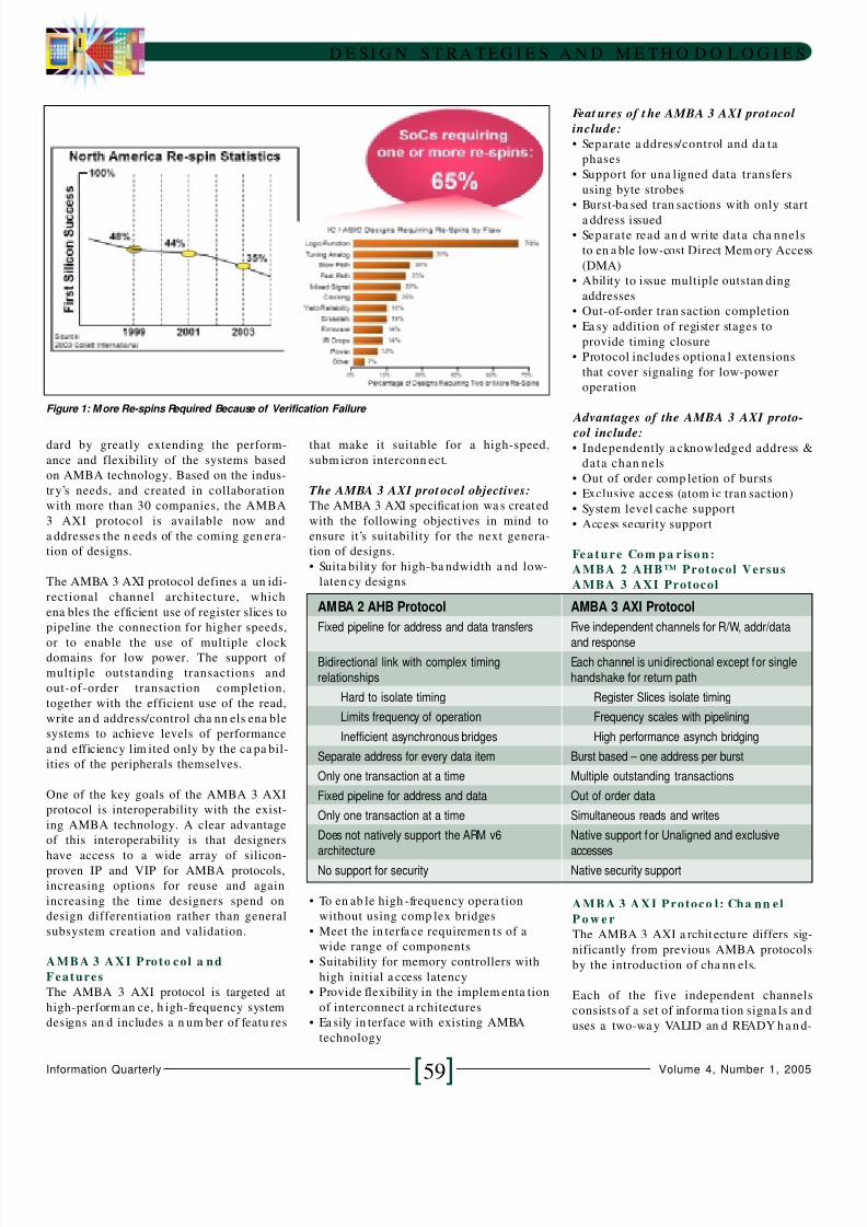
Eff i c i enc y Com pa r ison:AMBA 2 AHB Proto co l Versus
AMBA 3 AXI Protocol
AMBA 3 AXI Protocol:
Inte rc onn e c ts and Inte r fac e s
The specification provides a single proto-
col definition for describing in terfaces:
• Between a master and the interconnect
• Between a slave and the interconnect
• Between a m aster and a slave
In most systems, the address channel
bandwidth requirement is significantly
less than for the data channel. Such sys-
tems can achieve a good balance between
system performance and interconnect
complexity by using a shared address bus
with m ultiple data buses to enable para l-
lel data tran sfers.
The AMBA 3 AXI protocol enables a vari-
ety of different interconnect implementa-
tions.
Most systems use one of three intercon n ectapproaches:
• Sha red Address a nd Single Data buses
(SASD)
• Sha red Address buses an d Multiple data
buses (SAMD)
• Multi-layer with Multiple Address buses
a nd Multiple Data buses (MAMD)
With SASD, one master and slave can be
active per channel. When one master
sends an address to one slave, no other
master can use the address bus. This is
similar to the structure of the AMBA 2
specification.
With SAMD, one m aster an d sla ve ca n be
active per address cha nn el. Multiple ma s-
ters an d slave pa irs can be active on oth er
channels (Read/Write Data and Response
cha nn el). For exa m ple, if m aster1 sends
write data to slave1, master2 can send
write data to slave2 at the sam e time a nd
does not h ave to wa it for bus being freed
The number of active pairs is design
dependent. Obviously the parallel nature
of this operation significantly improves
the performa nce of the subsystem.
With MAMD, mu ltiple pa irs can be a ctive
on the a ddress cha nn els. This provides the
maximum of interconnect flexibility and
yields the highest performance subsystem
interconnect architecture. This topology is
also the most complex scenario to verify
as multiple masters and slaves can be
active at a ny tim e. Verifying th e interac-
tion between a ll ports will be critical to th e
successful operation of the resulting sys-
tem.
The details of the implementation of
SASD, SAMD an d MAMD a re design -spe-
cific and outside the scope of this paper.
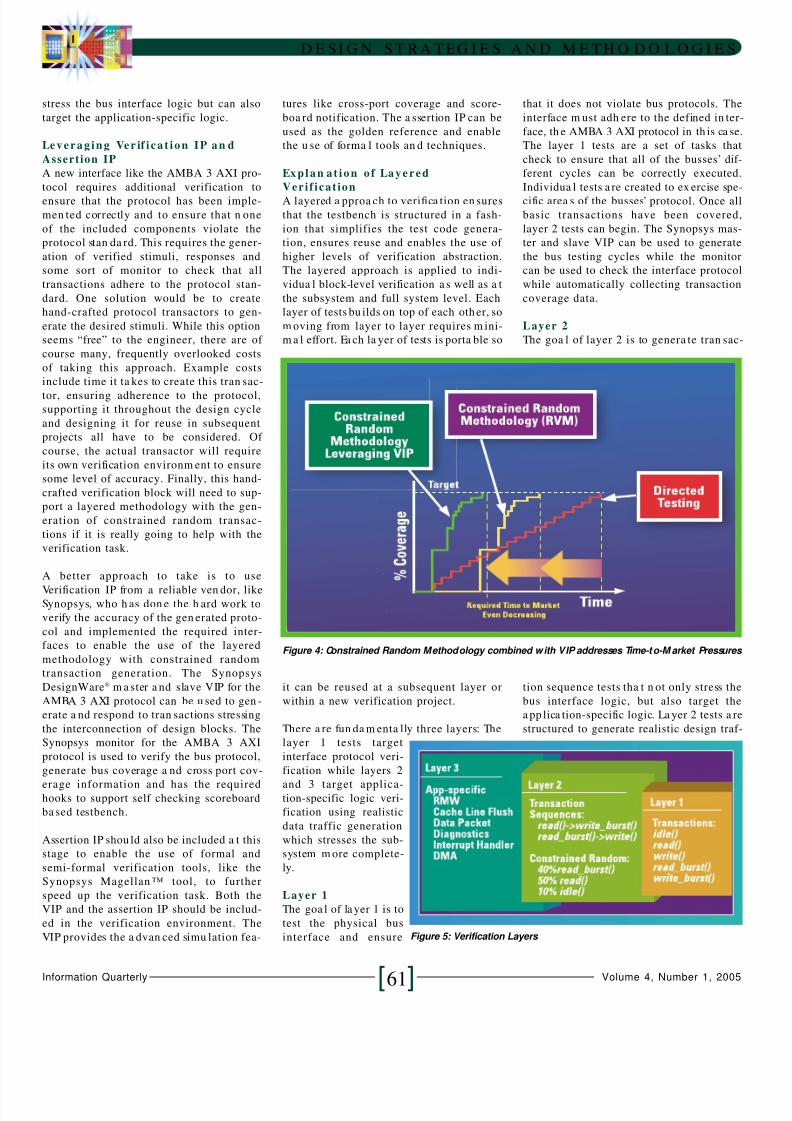
De pl oym e nt o f a Laye r e d
Cons tr a i ne d Random Ve r if i c at i on
M e t h o d o l o g y
Deployment of a layered verification
methodology combined with the use of
constrained random verification tech-
niques are required to meet the challenge
of verifying a subsystem which uses the
AMBA 3 AXI protocol. As discussed ea rlier,
a directed testing m ethodology ca nn ot cre-
ate enough system stimuli to reach the
required coverage goals in the shortened
design cycle.
The Synopsys Reference Verification
Metho dology (RVM) is on e exa m ple of a
reusable la yered verification m ethodology
that employs constrained random tech-
niques to achieve full coverage in the
shortest possible time and effort. Reuse is
another key consideration with verifica-
tion as well as with IP. The verification
methodology must support reuse such
that tests at one hierarchical level can mereused at th e nex t level up, a s well as with
the next project. The structure of RVM
ena bles this.
With a layered verification approach,
lower layers like protocol verification are
reused a t h igher levels. Tests written for th e
lowest levels, protocol validation are
reused at the higher levels where the veri-
fication focus shifts to generating and ver-
ifying tran saction sequences tha t not on ly
Figure 2: Cycles for the AMBA 2 AHB Protocol
Figure 3: Cycles for the AMBA 3 AXI Protocol
8/2/2019 Paper on AXI
http://slidepdf.com/reader/full/paper-on-axi 4/5
D E SI G N S T R A TEG I E S A N D M E T H O D O L O G I E S
Volume 4, Number 1, 2005Information Quarterly [61]
stress the bus interface logic but can also
target the application-specific logic.
Le ve r agi ng Ve r if i c at i on IP an d
Assertion IP
A new interface like the AMBA 3 AXI pro-
tocol requires additional verification to
ensure that the protocol has been imple-
men ted correctly and to ensure that n one
of the included components violate the
protocol stan da rd. This requires the gener-
ation of verified stimuli, responses and
some sort of monitor to check that all
transactions adhere to the protocol stan-
dard. One solution would be to create
hand-crafted protocol transactors to gen-
erate the desired stimuli. While this option
seems “free” to the engineer, there are of
course many, frequently overlooked costs
of taking this approach. Example costs
include time it ta kes to create this tran sac-
tor, ensuring adherence to the protocol,supporting it throughout the design cycle
and designing it for reuse in subsequent
projects all have to be considered. Of
course, the actual transactor will require
its own verification environm ent to ensure
some level of accuracy. Finally, this hand-
crafted verification block will need to sup-
port a layered methodology with the gen-
eration of constrained random transac-
tions if it is really going to help with the
verification task.
A better approach to take is to use
Verification IP from a reliable ven dor, likeSynopsys, who h as don e the h ard work to
verify the accuracy of the gen erated proto-
col and implemented the required inter-
faces to enable the use of the layered
methodology with constrained random
transaction generation. The Synopsys
DesignWare® m a ster a nd slave VIP for the
AMBA 3 AXI protocol can be u sed to gen -
erate a nd respond to tran sactions stressing
the interconnection of design blocks. The
Synopsys monitor for the AMBA 3 AXI
protocol is used to verify the bus protocol,
generate bus coverage a nd cross port cov-
erage information and has the requiredhooks to support self checking scoreboard
ba sed testbench.
Assertion IP shou ld also be included a t this
stage to enable the use of formal and
semi-formal verification tools, like the
Synopsys Magellan ™ tool, to further
speed up the verification task. Both the
VIP and the assertion IP should be includ-
ed in the verification environment. The
VIP provides the a dvan ced simu lation fea-
tures like cross-port coverage and score-
boa rd notification. The a ssertion IP can be
used as the golden reference and enable
the u se of forma l tools an d techniques.
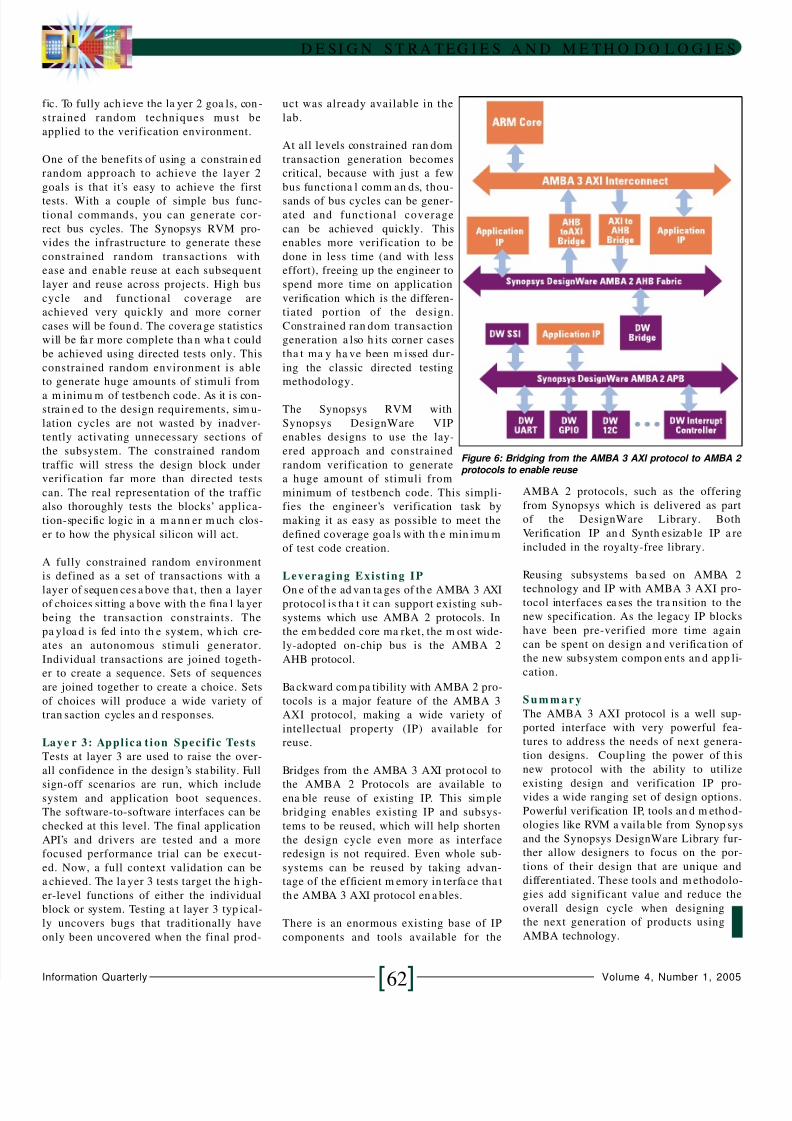
Expl an at i on of Laye r e d
Veri f icat ion
A layered a pproa ch to verifica tion en sures
that the testbench is structured in a fash-
ion that simplifies the test code genera-
tion, ensures reuse and enables the use of
higher levels of verification abstraction.
The layered approach is applied to indi-
vidua l block-level verification a s well as a t
the subsystem and full system level. Each
layer of tests bu ilds on top of each oth er, so
m oving from layer to layer requires m ini-
m a l effort. Ea ch la yer of tests is porta ble so
it can be reused at a subsequent layer or
within a new verification project.
There a re fun da m enta lly three layers: The
layer 1 tests target
interface protocol veri-
fication while layers 2
and 3 target applica-tion-specific logic veri-
fication using realistic
data traffic generation
which stresses the sub-
system m ore complete-
ly.
Layer 1
The goa l of la yer 1 is to
test the physical bus
interface and ensure
that it does not violate bus protocols. The
interface m ust adh ere to the defined in ter-
face, th e AMBA 3 AXI protocol in th is ca se.
The layer 1 tests are a set of tasks that
check to ensure that all of the busses’ dif-
ferent cycles can be correctly executed.
Individua l tests a re created to ex ercise spe-
cific area s of the busses’ protocol. Once all
basic transactions have been covered,
layer 2 tests can begin. The Synopsys mas-
ter and slave VIP can be used to generate
the bus testing cycles while the monitor
can be used to check the interface protocol
while automatically collecting transaction
coverage data.
Layer 2
The goa l of layer 2 is to genera te tran sac-
tion sequence tests tha t n ot only stress the
bus interface logic, but also target the
a pp lica tion-specific logic. La yer 2 tests a re
structured to generate realistic design traf-
Figure 4: Constrained Random Methodology combined with VIP addresses Time-to-M arket Pressures
Figure 5: Verification Layers
8/2/2019 Paper on AXI
http://slidepdf.com/reader/full/paper-on-axi 5/5
D E SI G N S T R A TEG I E S A N D M E T H O D O L O G I E S
Volume 4, Number 1, 2005Information Quarterly [62]
fic. To fully ach ieve the la yer 2 goa ls, con -
strained random techniques must be
applied to the verification environment.
One of the benefits of using a constrain ed
random approach to achieve the layer 2
goals is that it’s easy to achieve the first
tests. With a couple of simple bus func-
tional commands, you can generate cor-
rect bus cycles. The Synopsys RVM pro-
vides the infrastructure to generate these
constrained random transactions with
ease and enable reuse at each subsequent
layer and reuse across projects. High bus
cycle and functional coverage are
achieved very quickly and more corner
cases will be foun d. The covera ge statistics
will be fa r more complete tha n wha t could
be achieved using directed tests only. This
constrained random environment is able
to generate huge amounts of stimuli from
a m inimu m of testbench code. As it is con-strain ed to the design requirements, sim u-
lation cycles are not wasted by inadver-
tently activating unnecessary sections of
the subsystem. The constrained random
traffic will stress the design block under
verification far more than directed tests
can. The real representation of the traffic
also thoroughly tests the blocks’ applica-
tion-specific logic in a m a nn er m uch clos-
er to how the physical silicon will act.
A fully constrained random environment
is defined as a set of transactions with a
layer of sequen ces a bove tha t, then a layerof choices sitting a bove with th e fina l la yer
being the transaction constraints. The
pa yloa d is fed into th e system, wh ich cre-
ates an autonomous stimuli generator.
Individual transactions are joined togeth-
er to create a sequence. Sets of sequences
are joined together to create a choice. Sets
of choices will produce a wide variety of
tran saction cycles an d responses.
Laye r 3: Appl ica t ion Speci f ic Tests
Tests at layer 3 are used to raise the over-
all confidence in the design ’s stability. Full
sign-off scenarios are run, which includesystem and application boot sequences.
The software-to-software interfaces can be
checked at this level. The final application
API’s and drivers are tested and a more
focused performance trial can be execut-
ed. Now, a full context validation can be
a chieved. The la yer 3 tests target the h igh-
er-level functions of either the individual
block or system. Testing a t layer 3 typ ical-
ly uncovers bugs that traditionally have
only been uncovered when the final prod-
uct was already available in the
lab.
At all levels constrained ran dom
transaction generation becomes
critical, because with just a few
bus functiona l comm an ds, thou-
sands of bus cycles can be gener-
ated and functional coverage
can be achieved quickly. This
enables more verification to be
done in less time (and with less
effort), freeing up the engineer to
spend more time on application
verification which is the differen-
tiated portion of the design.
Constrained ran dom transaction
generation a lso h its corner cases
tha t ma y ha ve been m issed dur-
ing the classic directed testing
methodology.
The Synopsys RVM with
Synopsys DesignWare VIP
enables designs to use the lay-
ered approach and constrained
random verification to generate
a huge amount of stimuli from
minimum of testbench code. This simpli-
fies the engineer’s verification task by
making it as easy as possible to meet the
defined coverage goa ls with th e min imu m
of test code creation.
Leveraging Exist ing IP
On e of th e ad van ta ges of th e AMBA 3 AXIprotocol is tha t it can support existing sub-
systems which use AMBA 2 protocols. In
the em bedded core ma rket, the m ost wide-
ly-adopted on-chip bus is the AMBA 2
AHB protocol.
Ba ckward com pa tibility with AMBA 2 pro-
tocols is a major feature of the AMBA 3
AXI protocol, making a wide variety of
intellectual property (IP) available for
reuse.
Bridges from th e AMBA 3 AXI protocol to
the AMBA 2 Protocols are available toena ble reuse of existing IP. This sim ple
bridging enables existing IP and subsys-
tems to be reused, which will help shorten
the design cycle even more as interface
redesign is not required. Even whole sub-
systems can be reused by taking advan-
tage of the efficient m emory in terfa ce tha t
th e AMBA 3 AXI protocol en a bles.
There is an enormous existing base of IP
components and tools available for the
AMBA 2 protocols, such as the offering
from Synopsys which is delivered as part
of the DesignWare Library. Both
Verification IP an d Synth esizab le IP a re
included in the royalty-free library.
Reusing subsystems ba sed on AMBA 2
technology and IP with AMBA 3 AXI pro-tocol interfaces ea ses the tra nsition to the
new specification. As the legacy IP blocks
have been pre-verified more time again
can be spent on design a nd verifica tion of
the new subsystem compon ents an d app li-
cation.
S u m m a r y
The AMBA 3 AXI protocol is a well sup-
ported interface with very powerful fea-
tures to address the needs of next genera-
tion designs. Coup ling the power of th is
new protocol with the ability to utilize
existing design and verification IP pro-vides a wide ranging set of design options.
Powerful verification IP, tools an d m etho d-
ologies like RVM a vaila ble from Synop sys
and the Synopsys DesignWare Library fur-
ther allow designers to focus on the por-
tions of their design that are unique and
differentiated. These tools and m ethodolo-
gies add significant value and reduce the
overall design cycle when designing
the next generation of products using
AMBA technology.
Figure 6: Bridging from the AMBA 3 AXI protocol to AMBA 2protocols to enable reuse


![LogiCORE IP AXI to APB Bridge v2 - XilinxThe 32-bit AXI4-Lite interface on the AXI to APB Bridge core is based on the AMBA AXI and ACE Protocol Specification v2.0 [Ref 1]. The core](https://img.pdfslide.net/doc/110x75/5ea76a1bf3eb741af75f6d89/logicore-ip-axi-to-apb-bridge-v2-xilinx-the-32-bit-axi4-lite-interface-on-the.jpg)

![AXI Protocol Checker v1 - Xilinx · The AXI Protocol Checker core monitors AXI interfaces. When attached to an interface, it ... See ARM AMBA® AXI Protocol v2.0 [Ref 1]. Performance](https://img.pdfslide.net/doc/110x75/5b158bc17f8b9ac7128d1298/axi-protocol-checker-v1-xilinx-the-axi-protocol-checker-core-monitors-axi.jpg)