Embed Size (px)
Citation preview
. _._.
P .
WOODWARD
PART III
*c
ii .J
PARALLEL
OPERATION OF ALTERNATORS
.
I
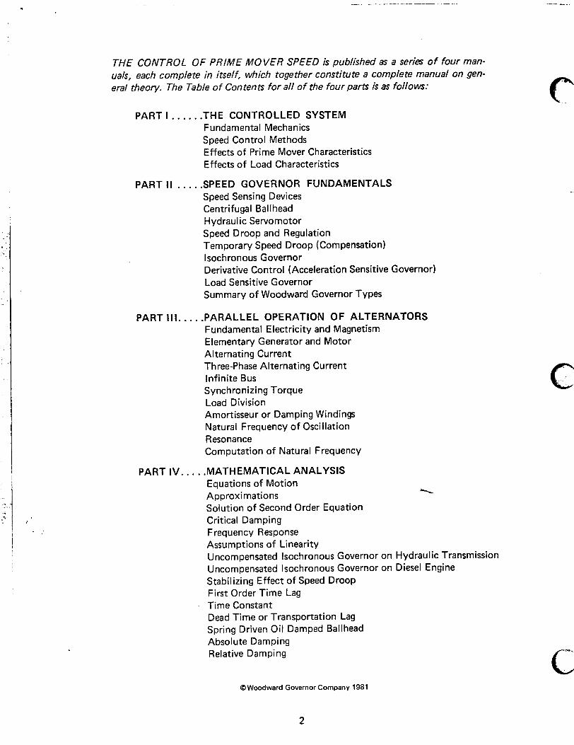
THE CONTROL OF PRIME MOVER SPEED is published as a series of four man- uals, each complete in itself, which together constitute a complete manual on gen- eral theory. The Table of Contents for all of the four parts is as follows:
PART I . . . . . .THE CONTROLLED SYSTEM Fundamental Mechanics Speed Control Methods Effects of Prime Mover Characteristics Effects of Load Characteristics
PARTII . . . , .SPEED GOVERNOR FUNDAMENTALS Speed Sensing Devices Centrifugal Ballhead Hydraulic Servomotor Speed Droop and Regulation Temporary Speed Droop (Compensation) lsochronous Governor Derivative Control (Acceleration Sensitive Governor) Load Sensitive Governor Summary of Woodward Governor Types
PART Ill.. . . .PARALLEL OPERATION OF ALTERNATORS Fundamental Electricity and Magnetism Elementary Generator and Motor Alternating Current Three-Phase Alternating Current Infinite Bus Synchronizing Torque Load Division Amortisseur or Damping Windings Natural Frequency of Oscillation Resonance Computation of Natural Frequency
PART IV. . . . .MATHEMATICAL ANALYSIS Equations of Motion Approximations Solution of Second Order Equation Critical Damping Frequency Response Assumptions of Linearity Uncompensated lsochronous Governor on Hydraulic Transmission Uncompensated lsochronous Governor on Diesel Engine Stabilizing Effect of Speed Droop First Order Time Lag Time Constant Dead Time or Transportation Lag Spring Driven Oil Damped Ballhead Absolute Damping Relative Damping
c
c .
P. c @Woodward Governor Company 1981
2
MANUAL 2503 I
THE CONTROL OF PRIME MOVER SPEED
PART III
PARALLEL OPERATION OF ALTERNATORS
This manual, with Parts I and II, replaces our Manual 25010 “Fundamentals of Speed Governing.” It also replaces 25016 “Parallel Operation of Engine Driven Alternators” and much of 25012 “General Requirements for Wood- ward Governor Application to Internal Combustion Engines.”
t i
i :
3
THE CONTROL OF PRIME MOVER SPEED
PART Ill: PARALLEL OPERATION OF ALTERNATORS
Despite the fact that alternating current generators, commonly called alternators, with their driving prime movers and controlling governors, have been in widespread use in parallel operation for many years, there is a general lack of understanding of such systems even on the part of many operators and engineers directly concerned. As a result we are frequently called upon to correct troubles which not only do not originate in the governor but about which the governor can do little or nothing.
A simple engine driven alternator supplying an iso- lated nonsynchronous load is relatively easy to un- derstand; but parallel two synchronous units and tremendous changes take place. Governor knobs that adjusted speed now affect load division, mech- anical oscillations of the throttle and periodic ex- changes of load between alternators arise, and units that performed beautifully alone kick up such a fuss that they won’t stay on the line.
Paralleling obviously does not always produce such violent results, but the potential for such behavior in some degree always exists in parallel operation, and this degree is greatly influenced by the charac- teristics of the controlled unit. For a better under- standing of these characteristics we will turn our attention to the alternating current generator.
It is obvious that a simple, nontechnical discussion of alternating current and alternators cannot be very comprehensive, but it is hoped that alternator be- havior can be made to seem reasonable by means of
.I the oversimplified and nonrigorous explanations which will follow.
If an electrical conductor (a wire) is passed sidewise through a magnetic field, a voltage is induced in it, and if a circuit including the conductor is com- pleted, this generated voltage will cause a current to flow. As soon as the current is established, force is required to move the conductor through the field and electrical power is developed from the mechan- ical work done in the conductor during such move- ment. This is a GENERATOR in its simplest form. Conversely, if some outside source of voltage causes
a current to flow through the conductor in the mag- netic field, force is required to restrain the conduc- tor from moving, and if it is permitted to move against such a restraining force, mechanical work is done. This is the simplest element of a MOTOR.
In an ALTERNATOR the magnetic field is generally established by causing direct current to flow through coils wound on part of the iron structure of the magnetic path - usually, in the larger machines, on the rotating member or ROTOR. Since voltage is generated whether the conductor moves across the field or the field across the conductor, we may choose that the conductor remain stationary while the field rotates. Such an arrangement of nonrota- ting conductors and iron constitutes the STATOR. If alternate north and south magnetic poles pass a conductor in the stator, the direction of the induced voltage, and hence the current, reverses periodical- ly and an ALTERNATING CURRENT results
c ’ The generated voltage in this instance will rise to a maximum value in one direction, decrease through zero to a like maximum in the other direction, again decrease through zero and rise to a maximum in the initial direction. The variation of voltage from one maximum to the next maximum in the same di- rection constitutes one CYCLE. In most power gen- erating alternators the machines are so designed and the speeds so chosen that a cycle is completed sixty times per second. That-is, the generated voltage has a FREQUENCY of 60 cycles per second.
The conductors of the stator, arranged in coils, can be so placed that the maximum voltage in two sep- arate windings will be reached at different times. For instance, consider again a rotor having one north and one south pole. A conductor at a given point in the stator will have a 60-cycle voltage gen- erated in it if the rotor makes 60 revolutions per second or 3600 rpm. Another conductor, placed 120” around the stator in the direction of rotation, will reach its maximum at a later time. If we con- sider one cycle to include 360 electrical which in this example is produced in 360 mechani cal degrees rotation of the rotor, the
4
will reach its maximum 120” later than the first and may be said to be lagging the first in PHASE by 120 electrical
0
degrees, If a third conductor is placed an additional 120” around the stator, the three voltages
- generated will differ in phase by 120”. This is the
; usual 3-phase voltage relationship. Had the rotating field been made with 4 poles instead of 2, the stator
! conductors would have been spaced 60 mechanical degrees apart and 60 cycles would have been pro- duced at 1800 rpm. The electrical phase relation-
. ship, however, would have remained 120 electrical degrees. The conductors of such a stator are so con- nected, that, normally, three terminals result, the voltage between any pair being 120 electrical degrees out of phase with the other two voltages. Since this 3-phase voltage at the terminals results from a rotating magnetic field of constant strength, it is not unreasonable to assume that if, conversely, an identical 3-phase voltage were connected to the terminals from an external source, a rotating mag- netic field of constant strength would result. This is, in fact, the case, and accounts for some of the phen- omena with which we will be concerned.
Consider a source of such a voltage having a fixed frequency, unchangeable by anything which we can
onnect to it; this is the so-called INFINITE BUS. f this source is connected to one side of an open
3-blade switch and our engine-driven alternator so connected to the other side that phase-rotation, phase, frequency, and voltage are respectively the same, the switch may be closed with no flow of power to or from our alternator. Thus, so far as the engine is concerned, the condition is no different than before the switch was closed so long as the above conditions exist. However, the dynamic char- acteristics of the system which the governor must control have changed greatly, and the effect of this change will be discussed later. The operation just described is performed whenever an alternator is
l SYNCHRONIZED and put on the line.
6 If now fuel is increased to the engine, it will try to speed up, but it is no longer free to do so, except momentarily, being forced to run at the average dictated by the infinite bus frequency so long as the alternator SYNCHRONIZING TORQUE is not exceeded. This torque results from the interaction between the rotating field established by connec- tion of the alternator stator to the bus (the synchro- nous field) and the DC field of the alternator rotor. So long as they are in phase (that is, lined up) no
I torque or turning effort exists; if the rotor field
leads in phase a restraining torque is exerted, work has to be done by the engine and power flows to the bus; if the rotor lags a driving torque results, power is taken from the bus and the alternator is said to be “motored.” Thus there is a torque proportional to the angle between rotor field and synchronous field and in the direction tending to decrease that angle to zero. The effect of this is as though the engine were connected to its load through a torsion spring. Since the speed normally changes only a very small percentage, the power fed to the bus or taken from it is also proportional to the angle by which the rotor leads or lags the rotating AC field; that is the amount the “torsion spring” is wound up, one way or the other.
If two alternators are paralleled a synchronizing torque exists between them whether connected to a load or not because they are connected to each other, in effect, by the “torsion springs.” In this case, however, speed changes are possible if there is no isochronous (constant speed) governor in the sys- tem, as will be shown later.
This “wind-up” of the spring in the comparison above is equivalent to displacement of the alternator DC field to lead the synchronous field set up by the line frequency in the actual case. The analogy also holds for the condition of lagging DC field in which power is taken from the line to “motor” the alter- nator; and for all intermediary conditions including the “lined-up” configuration of now power trans- mitted, which is desired when putting the unit on or off the line.
We will now consider the effect of this synchroniz- ing torque on the steady-state parallel operation of governed engine-alternator units.
One of the primary considerations in the parallel operation of power generating machines is the proper division of load. As implied in Part I I of The Control of Prime Mover Speed series, this can be accomplished by providing a governor with speed droop which results in governor system regulation.
This relationshp of regulation to load division is perhaps best explained by reference to the speed vs. load characteristic curves for the governor-engine combinations involved, bearing in mind that the units, when paralleled through alternators, are com- pelled to run at the same or, if the alternators have different numbers of poles, proportional speeds. For simplicity we will refer to the normal speed as 100%
5
;- t
I I
,
speed and full load as 100% load, and will assume diesel engines as prime movers.
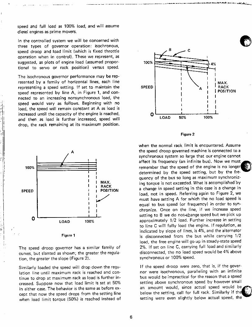
In the controlled system we will be concerned with three types of governor operation: isochronous, speed droop and load limit (which is fixed throttle operation when in control). These we represent, as suggested, as plots of engine load (assumed propor- tional to servo or rack position) versus speed.
100%
The isochronous governor performance may be rep- resented by a family of horizontal lines, each line representing a speed setting. If set to maintain the speed represented by line A, in Figure 1, and con- nected to an increasing nonsynchronous load, the speed would vary as follows. Beginning with no load, the speed will remain constant at A as load is increased until the capacity of the engine is reached, and then as load is further increased, speed will drop, the rack remaining at its maximum position.
SPEED
0
100%
SPEED
0
I I MAX.
I I RACK
I 1 POSITION
I ’ /
’ I I I I
/ LOAD 100%
Figure 1
The speed droop governor has a similar family of curves, but slanted as shown; the greater the regula- tion, the greater the slope (Figure 2).
Similarly loaded the speed will drop down the regu- lation line until maximum rack is reached and con- tinue to drop at maximum rack as load is further in- creased. Suppose now that load limit is set at 50% in either case. The behavior is the same as before ex- cept that now the speed drops from the setting line when load limit torque (50%) is reached instead of
I
\ ’ I
I Ai’
MAX. _.
I
RACK 1 1 POSITION
I I 1
I I
1 ;
I I , 1
LOAD 50% 100%
Figure 2
when the normal rack limit is encountered. Assume the speed droop governed machine is connected to a synchronous system so large that our engine cannot affect its frequency (an infinite bus). Now we must remember that the speed of the engine is no longer determined by the speed setting, but by the fre- quency of the bus so long as maximum synchroniz- ing torque is not exceeded. What is accomplished’by a change in speed setting in this case is a change in load, not in speed. Referring again to Figure 2, we must have setting A for which the no load speed is equal to bus speed (or frequency) in order to syn- chronize. Once on the line, if we increase speed setting to B we do notdange speed but we pick up approximately l/2 load. Further increase in setting to line C will fully load the engine. If regulation, as indicated by slope of lines, is 4%, and the alternator is disconnected from the bus while carrying l/2 load, the free engine will go up in steady-state speed 2%. If set on line C, carrying full load and similarly disconnected, the no load speed would be 4% above synchronous or 100% speed.
If the speed droop were zero, that is, if the gover- nor were isochronous, paralleling with an infinite bus would be impractical for the reason that a speed setting above synchronous speed by however small an amount would, since actual speed would be below the setting, call for full rack. Similarly if th setting were even slightly below actual speed,
6
A.-‘--
racks would go to fuel off position. Therefore, gov- ernors should not be paralleled isochronously with any system so big that the governed unit cannot affect its speed.
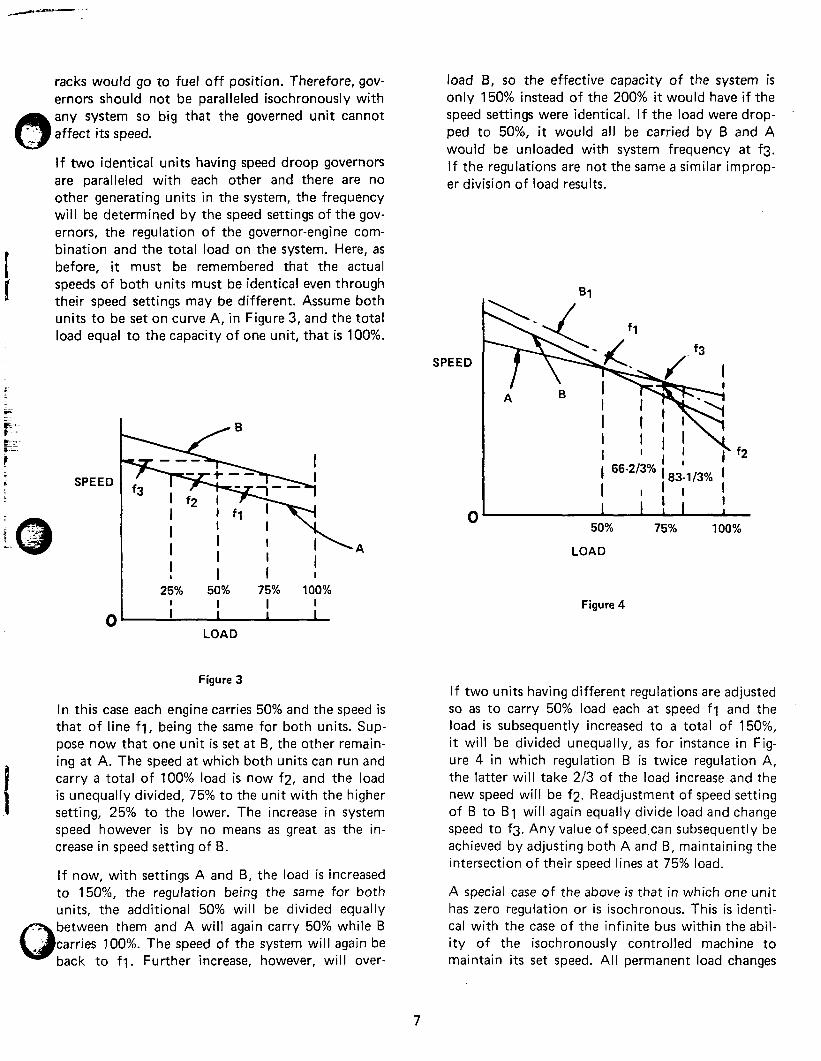
If two identical units having speed droop governors are paralleled with each other and there are no other generating units in the system, the frequency will be determined by the speed settings of the gov- ernors, the regulation of the governor-engine com- bination and the total load on the system. Here, as before, it must be remembered that the actual speeds of both units must be identical even through their speed settings may be different. Assume both units to be set on curve A, in Figure 3, and the total load equal to the capacity of one unit, that is 100%.
SPEED
0
25% 50% 75% 100%
; I I I I I I
LOAD
Figure 3
In this case each engine carries 50% and the speed is that of line fl, being the same for both units. Sup- pose now that one unit is set at B, the other remain- ing at A. The speed at which both units can run and carry a total of 100% load is now f2, and the load is unequally divided, 75% to the unit with the higher setting, 25% to the lower. The increase in system speed however is by no means as great as the in- crease in speed setting of B.
If now, with settings A and B, the load is increased to 150%, the regulation being the same for both units, the additional 50% will be divided equally between them and A will again carry 50% while B carries 100%. The speed of the system will again be back to fl. Further increase, however, will over-
load B, so the effective capacity of the system is only 150% instead of the 200% it would have if the speed settings were identical. If the load were drop- ped to 50%, it would all be carried by B and A would be unloaded with system frequency at f3. If the regulations are not the same a similar improp- er division of load results.
SPEED
0
i SS-213% i &,
50% 75% 100%
LOAD
Figure 4
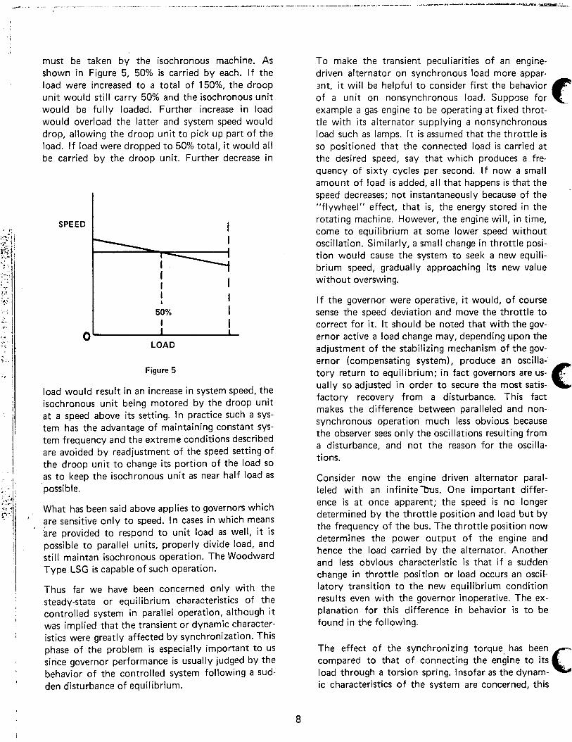
If two units having different regulations are adjusted so as to carry 50% load each at speed fl and the load is subsequently increased to a total of 150%, it will be divided unequally, as for instance in Fig- ure 4 in which regulation B is twice regulation A, the latter will take 2/3 of the load increase and the new speed will be f2. Readjustment of speed setting of B to B1 will again equally divide load and change speed to f3. Any value of speed.can subsequently be achieved by adjusting both A and B, maintaining the intersection of their speed lines at 75% load.
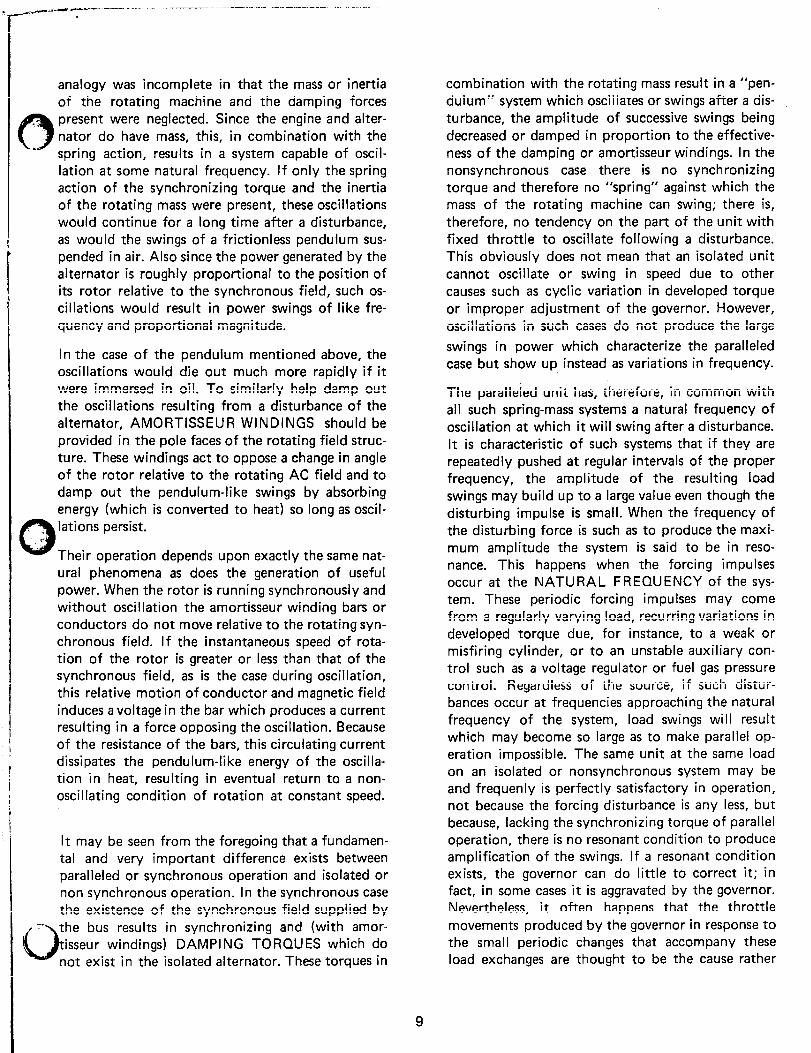
A special case of the above is that in which one unit has zero regulation or is isochronous. This is identi- cal with the case of the infinite bus within the abil- ity of the isochronously controlled machine to maintain its set speed. All permanent load changes
7
.i must be taken by the isochronous machine. As shown in Figure 5, 50% is carried by each. If the load were increased to a total of 150%, the droop unit would still carry 50% and the isochronous unit would be fully loaded. Further increase in load would overload the latter and system speed would drop, allowing the droop unit to pick up part of the load. If load were dropped to 50% total, it would all be carried by the droop unit. Further decrease in
SPEED I
I 1
I 0
LOAD
Figure 5
load would result in an increase in system speed, the isochronous unit being motored by the droop unit at a speed above its setting. In practice such a sys- tem has the advantage of maintaining constant sys- tem frequency and the extreme conditions described are avoided by readjustment of the speed setting of the droop unit to change its portion of the load so as to keep the isochronous unit as near half load as possible.
What has been said above applies to governors which are sensitive only to speed. In cases in which means are provided to respond to unit load as well, it is possible to parallel units, properly divide load, and still maintan isochronous operation. The Woodward Type LSG is capable of such operation.
i Thus far we have been concerned only with the steady-state or equilibrium characteristics of the controlled system in parallel operation, although it I was implied that the transient or dynamic character- istics were greatly affected by synchronization. This phase of the problem is especially important to us since governor performance is usually judged by the behavior of the controlled system following a sud- den disturbance of equilibrium.
To make the transient peculiarities of an engine- driven alternator on synchronous load more appar- znt, it will be helpful to consider first the behavior of a unit on nonsynchronous load. Suppose for . c example a gas engine to be operating at fixed throt- tle with its alternator supplying a nonsynchronous load such as lamps. It is assumed that the throttle is so positioned that the connected load is carried at the desired speed, say that which produces a fre- quency of sixty cycles per second. If now a small amount of load is added, all that happens is that the speed decreases; not instantaneously because of the “flywheel” effect, that is, the energy stored in the rotating machine. However, the engine will, in time, come to equilibrium at some lower speed without oscillation. Similarly, a small change in throttle posi- tion would cause the system to seek a new equili- brium speed, gradually approaching its new value without overswing.
If the governor were operative, it would, of course sense the speed deviation and move the throttle to correct for it. It should be noted that with the gov- ernor active a load change may, depending upon the adjustment of the stabilizing mechanism of the gov- ernor (compensating system), produce an oscilla-’ tory return to equilibrium; in fact governors are us- ually so adjusted in order to secure the most satis- factory recovery from a disturbance. This fact makes the difference between paralleled and non- synchronous operation much less obvious because the observer sees only the oscillations resulting from a disturbance, and not the reason for the oscilla- tions.
Consider now the engine driven alternator paral- leled with an infinite’7Xls. One important differ- ence is at once apparent; the speed is no longer determined by the throttle position and load but by the frequency of the bus. The throttle position now determines the power output of the engine and hence the load carried by the alternator. Another and less obvious characteristic is that if a sudden change in throttle position or load occurs an oscil- latory transition to the new equilibrium condition results even with the governor inoperative. The ex- planation for this difference in behavior is to be found in the following.
The effect of the synchronizing torque has been compared to that of connecting the engine to its -
.. load through a torsion spring. Insofar as the dynam- c
ic characteristics of the system are concerned, this
8
-~--;’ -Ic-.-- ---.- __.- -~~-- ____ -~ ..-
analogy was incomplete in that the mass or inertia of the rotating machine and the damping forces present were neglected. Since the engine and alter- nator do have mass, this, in combination with the spring action, results in a system capable of oscil- lation at some natural frequency. If only the spring action of the synchronizing torque and the inertia of the rotating mass were present, these oscillations would continue for a long time after a disturbance, as would the swings of a frictionless pendulum sus- pended in air. Also since the power generated by the alternator is roughly proportional to the position of its rotor relative to the synchronous field, such os- cillations would result in power swings of like fre- quency and proportional magnitude.
In the case of the pendulum mentioned above, the oscillations would die out much more rapidly if it were immersed in oil. To similarly help damp out the oscillations resulting from a disturbance of the alternator, AMORTISSEUR WINDINGS should be provided in the pole faces of the rotating field struc- ture. These windings act to oppose a change in angle of the rotor relative to the rotating AC field and to damp out the pendulum-like swings by absorbing energy (which is converted to heat) so long as oscil- lations persist.
Their operation depends upon exactly the same nat- ural phenomena as does the generation of useful power. When the rotor is running synchronously and without oscillation the amot-tisseur winding bars or conductors do not move relative to the rotating syn- chronous field. If the instantaneous speed of rota- tion of the rotor is greater or less than that of the synchronous field, as is the case during oscillation, this relative motion of conductor and magnetic field induces a voltage in the bar which produces a current resulting in a force opposing the oscillation. Because of the resistance of the bars, this circulating current /
I
b dissipates the pendulum-like energy of the oscilla-
I tion in heat, resulting in eventual return to a non- I
I oscillating condition of rotation at constant speed.
It may be seen from the foregoing that a fundamen- tal and very important difference exists between paralleled or synchronous operation and isolated or non synchronous operation. In the synchronous case the existence of the synchronous field supplied by the bus results in synchronizing and (with amor- isseur windings) DAMPING TORQUES which do
exist in the isolated alternator. These torques in
combination with the rotating mass result in a “pen- dulum” system which oscillates or swings after a dis- turbance, the amplitude of successive swings being decreased or damped in proportion to the effective- ness of the damping or amortisseur windings. In the nonsynchronous case there is no synchronizing torque and therefore no “spring” against which the mass of the rotating machine can swing; there is, therefore, no tendency on the part of the unit with fixed throttle to oscillate following a disturbance. This obviously does not mean that an isolated unit cannot oscillate or swing in speed due to other causes such as cyclic variation in developed torque or improper adjustment of the governor. However, oscillations in such cases do not produce the large
swings in power which characterize the paralleled case but show up instead as variations in frequency.
The paralleled unit has, therefore, in common with all such spring-mass systems a natural frequency of oscillation at which it will swing after a disturbance. It is characteristic of such systems that if they are repeatedly pushed at regular intervals of the proper frequency, the amplitude of the resulting load swings may build up to a large value even though the disturbing impulse is small. When the frequency of the disturbing force is such as to produce the maxi- mum amplitude the system is said to be in reso- nance. This happens when the forcing impulses occur at the NATURAL FREQUENCY of the sys- tem. These periodic forcing impulses may come from a regularly varying load, recurring variations in developed torque due, for instance, to a weak or misfiring cylinder, or to an unstable auxiliary con- trol such as a voltage regulator or fuel gas pressure control. Regardless of the source, if such distur- bances occur at frequencies approaching the natural frequency of the system, load swings will result which may become so large as to make parallel op- eration impossible. The same unit at the same load on an isolated or nonsynchronous system may be and frequenly is perfectly satisfactory in operation, not because the forcing disturbance is any less, but because, lacking the synchronizing torque of parallel operation, there is no resonant condition to produce amplification of the swings. If a resonant condition exists, the governor can do little to correct it; in fact, in some cases it is aggravated by the governor. Nevertheless, it often happens that the throttle movements produced by the governor in response to the small periodic changes that accompany these load exchanges are thought to be the cause rather
9
than the result of the difficulty, as is actually the case. This can be demonstrated quite easily in most cases by blocking the throttles with the load limit or by other means. If the trouble is of the sort described above, the load swings will continue, al- though some change in magnitude may be obser- ved.
The preferred treatment of this problem is to avoid it by selection of the WKZ to give a natural frequen- cy well away from any possible forcing frequencies, such as the firing frequency of a given cylinder. In any case, the magnitude of the swings will be mini- mized by the introduction of the maximum feasible amount of damping. This is done in an alternator by the use of fully connected amortisseur windings in the field pole faces.
It should be noted that the natural frequency of oscillation of an alternator on synchronous load de- pends upon its inertia of WK* and the synchroniz- ing torque, which in turn depends upon the design of the alternator, the load carried, and the charac- teristics of the transmission line and paralleled gen- erating equipment. This fact makes double impor- tant the utilization of maximum damping in the amot-tisseur windings so that oscillations which do occur may be of minimum amplitude and die out as quickly as possible. In any event, the implication is that a range of frequencies must be avoided when designing spring drives or considering possible forc- ing impulses. In determining the required WK* so that resonance is avoided, the natural frequency of oscillation must be determined. For a single machine on an infinite bus this frequency is represented by the following equation:
P,xFK ~~35200 -
N I 1 WK2
in which
$ = natural frequency in cycles/minute
Pr = synchronizing power in KW/electrical radian F = system frequency in cycles/second WK2 = moment of inertia in pounds feet squared N = revolutions per minute of the machine
For two machines paralleled, the natural frequency of load exchange between them may be represented by:
35200 +1,2 = -
N1
PC1 x F
l F 2
X
=I 2 x
l+ - m2
2 \
P N2 2
l+Lx- [ li. 2 P r2 N1
For more machines in parallel it is possible by more complicated expressions to determine the natural frequencies of all the various modes of oscillation, as for instance with three units, No. 1 with No. 2, No. 2 with No. 3, No. 1 with No. 3. It is useful to know, however, that if all machines are computed accord- ing to the first formula for a single machine against an infinite bus, the natural frequencies of any pai in combination will lie between the lowest and high est figures obtained by such computation. The im- plication of this is that there should be no forcing frequencies within this entire range, or in fact within 20% of either end of the range.
Since in general, the forcing frequencies cannot be controlled, it follows that the range of natural fre- quencies of oscillation should be so established by choice of WK2 as to avoid resonance. Since this is only one considerati* in the choice of WK*, (others being engine criticals, speed deviation, speed recovery time and cost) difficulty in arriving at a satisfactory compromise is sometimes encountered.
The difference in control characteristics between a unit isolated and paralleled is of interest for another reason. The manner in which any control system be- haves is determined by the dynamic characteristics of the governed system. The purpose of governor adjustment is to so determine the governor charac- teristics that, when combined with those of the con- trolled system, satisfactory results are obtained. This implies first that the system is stable, that it returns to the desired equilibrium speed after disturbance; and second, that the speed (or load)
10
I .
deviation is not too great and that the error is cor- rected quickly and without excessive oscillation. It follows therefore that a change in system charac- teristics such as described above should be accom- panied by readjustments of the governor for best re- sults. This can be accomplished in the Woodward water wheel governors by use of the solenoid oper- ated bypass in the compensating system. However,
since this is not feasible in the case of the diesel governors, the adjustment used is necessarily a com- promise. In general a compromise can be found that is acceptable for all normal conditions of operation, but occasionally a unit has such bad paralleled char- acteristics that satisfactory performance both on and off the line is impossible with a single set of adjustments.
at the heart of the system
since 1870
Corporate Headquarters Rockford, Illinois, U.S.A. Branch Plants Fort Collins, Colorado, U.S.A. Stevens Point, Wisconsin, U.S.A. Sydney, N.S.W., Australia Subsidiary Operations Woodward Governor Nederland B.V. Hoofddorp, The Netherlands Woodward Governor (U.K.) Ltd. Slough, Berks., England Woodward Governor GmbH Lucerne, Switzerland and Hoofddorp, The Netherlands Woodward Governor (Quebec) Ltd. Montreal, Quebec, Canada Woodward Governor (Japan) Ltd. Tomisato, Chiba, Japan Woodward Governor (Reguladores) Limitada Campinas, S.P., Brazil WOODWARD GOVERNOR COMPANY Hydraulic Turbine Controls Division 5001 North Second Street P.O. Box 7001 Rockford, Illinois 61125-7001, U.S.A. Phone 615/877-7441-Telex 25-7410
P t ” ._ i
0