Embed Size (px)
Citation preview
The Manitoba Water Services Board SECTION 027060 Standard Construction Specifications PRESSURE PIPELINES Revised May 2015 Page 1 of 34
Part 1 General
1.1 DESCRIPTION OF WORK
.1 The work described shall consist of the construction of pressure pipelines including watermains, pipelines, forcemains, low pressure sewermains; including the supply and installation of pipe, appurtenances (crosses, tees, elbows, reducers, caps), as well as accessories such as couplings, service saddles, corporation stops, curb stops, thrust blocks, lubricant and including gate valves, hydrants, post hydrants and flushouts, the connection of the pipe to the source of water supply or to the point of discharge, as may be applicable; the hydrostatic and bacteriological testing of the pipe and the disinfection of pipes used to convey potable water and raw water.
1.2 CLASSIFICATION OF WORK
.1 PIPE - shall be classified on the following basis:
.1 Nominal inside diameter (nom. i.d.). Under no circumstances shall the actual inside diameter be less than 95% of the nom. i.d. specified on the Plans and/or Tender documents.
.2 Insulated or uninsulated. If not specified, pipe shall be uninsulated.
.3 Category of pressure pipeline based on use: .1 Watermain - to distribute potable water including water for fire
protection as part of an urban watermain distribution system in a town, village or city.
.2 Raw Water Pipeline – to convey non-potable water from well or surface water source to water treatment plant.
.3 Water Pipeline - to convey potable or raw water to rural residential consumers.
.4 Service Pipe – to convey potable water from pipeline or watermain to the residence.
.5 Forcemain - to convey sewage.
.6 Low Pressure Sewer - to collect raw sewage generally within a town or village.
The Manitoba Water Services Board SECTION 027060 Standard Construction Specifications PRESSURE PIPELINES Revised May 2015 Page 2 of 34
.4 Class of trench backfill (in accordance with Clauses 2.4 and 3.8 of Section 022180, "Pipeline Excavation, Bedding and Backfill"): .1 Common Backfill (if class of backfill is not specified, it shall be
"common") .2 Compacted Common Backfill .3 Compacted Select Granular Backfill .4 Unshrinkable Backfill
.2 .1 APPURTENANCES – Appurtenances shall be classified on the same basis as the Pipe (Clause 1.2.1) and on the basis of the type of appurtenances:
.1 Crosses
.2 Tees
.3 Elbows
.4 Reducers
.5 Caps
.2 ACCESSORIES – Accessories shall be defined as items required to complete the installation of watermain, pipeline, low pressure sewer or forcemain and shall include such items as: .1 Couplings and Pipe Restraints .2 Adaptors .3 Service Saddles .4 Curb Stops/Box and Corporation Stops .5 Thrust Blocks .6 Pipe lubricant and pipe gaskets .7 Nuts, bolts and washers
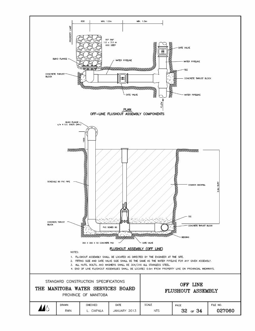
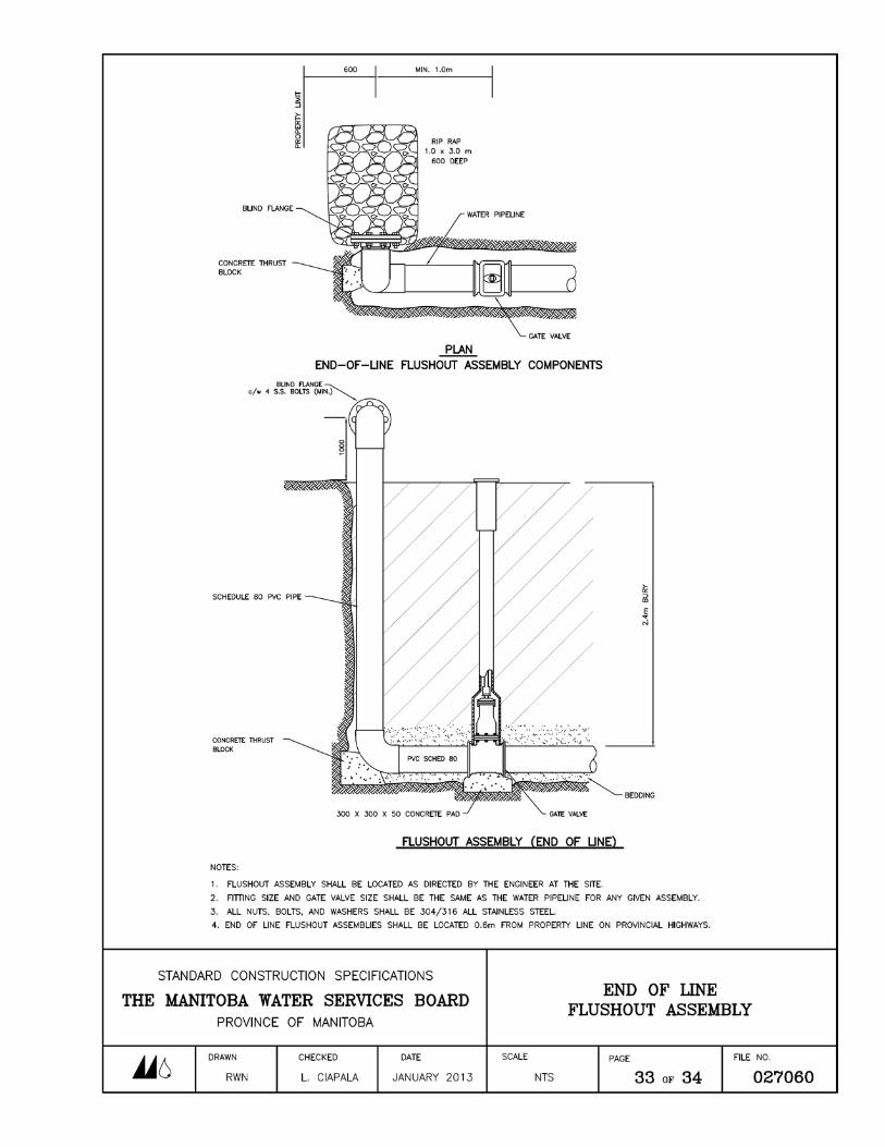
.3 HYDRANTS AND FLUSHOUT ASSEMBLIES – Hydrants and flushout assemblies may be subclassified as to: .1 on-line, off-line or end of line .2 bury depth (if not specified, it shall be 2.75 metres)
.4 GATE VALVES - Gate valves shall be as specified in part 2. 4 of this Section and compatible with the type of pipe installed.
The Manitoba Water Services Board SECTION 027060 Standard Construction Specifications PRESSURE PIPELINES Revised May 2015 Page 3 of 34
.3 CONNECTIONS - shall be classified either:
.1 Connection to water supply (for water mains or water pipelines), which may be subclassified as one of the following: .1 Connection to existing pipeline .2 Connection to existing gate valve .3 Connection to pipe with tee or tapping sleeve on existing pipeline
or main. .4 Connection to existing flushout .5 Connection to well
.2 Connection to point of discharge (for forcemains or low pressure sewers), which may be subclassified as either: .1 Connection to existing capped line .2 Construction of tee on existing line .3 Connection to existing manhole, lift station, or sewage wetwell (at
treatment plant, pumping station or outfall) .4 Connection to wastewater stabilization pond (lagoon)
1.3 STANDARDS
The following organizations publish Standards which have been referred to in this Section:
.1 AWWA –American Water Works Association 6666 West Quincy Avenue, Denver, Colorado USA 80235
.2 CSA International 178 Rexdale Boulevard, Toronto, Ontario M9W 1R3
.3 ASTM – American Society for Testing Materials 100 Barr Harbor Drive West Conshohocken, PA 19428-2959 USA
.4 CGSB – Canadian General Standards Board Place Du Portage 111, 6B1 111 Laurier Street Gatineau, QC K1A 1G6
The Manitoba Water Services Board SECTION 027060 Standard Construction Specifications PRESSURE PIPELINES Revised May 2015 Page 4 of 34
.5 WCU – Western Canadian Underwriters 3999 Henning Drive Burnaby, British Columbia V5C 6P9
.6 NSF International P.O. Box 130140 789 N. Dixboro Road Ann Arbor, MI USA 48113-0140
.7 PPI – Plastics Pipe Institute 105 Decker Court, Suite 825 Irving, TX USA 75062
.8 Water Quality Association International Headquarters and Laboratory 4151 Naperville Road Lisle, IL USA 60532-3696 Canadian Water Quality Association 295 The West Mall, Suite 330 Toronto, Ontario M9C 4Z4
The Standards referred to shall be the most recent edition.
1.4 QUALITY ASSURANCE
.1 CONCRETE - The Engineer shall carry out such tests on concrete (used in thrust blocks) as he considers necessary in accordance with the current CSA Standard A23.2, Methods of Testing for Concrete. Such tests shall be at the expense of the Owner except that the Contractor shall furnish any and all test samples free of charge. Water used for mixing concrete shall be clean and free of oil and alkali, organic matter or other deleterious substances. Water shall be equal to potable water in physical and chemical properties.
.2 PRESSURE TEST - The Contractor shall pressure test the pressure pipeline under the direct supervision of the Engineer.
.3 BACTERIOLOGICAL TESTS - Upon completion of pipelines or watermains intended to convey potable water, the Engineer shall take water samples and conduct bacteriological tests as he considers necessary.
The Manitoba Water Services Board SECTION 027060 Standard Construction Specifications PRESSURE PIPELINES Revised May 2015 Page 5 of 34
1.5 STORAGE AND HANDLING
.1 Pipe and other materials associated with the construction of pipelines, watermains, forcemains, and low pressure sewermains, shall be stored and handled in accordance with the recommendations of the respective manufacturers and to the satisfaction of the Engineer.
1.6 INSPECTION
.1 Inspection of the work described in this Section shall be performed by the Engineer.
Part 2 Products
2.1 PIPE
.1 PVC PIPE - The pipe shall be manufactured of Type 1 Grade 1 polyvinyl chloride 1120 in accordance with either of the two following alternatives:
.1 The pipe shall conform to the current ASTM Standard D1784, Standard for Rigid Polyvinyl Chloride Compound and D2241, Standard for Polyvinyl Chloride Plastic Pipe, and shall have CSA Certification to the current CSA Standard B137.3, Rigid Polyvinyl Chloride (PVC) Pipe for Pressure Applications. Each length of PVC pipe shall be clearly stamped with the CSA Certification Trademark Logo.
.2 The pipe shall conform to the current AWWA Standard C900, Standard for Polyvinyl Chloride Pressure Pipe.
Each length of pipe shall have an integral bell end with a rubber gasket as supplied by the pipe manufacturer. Pipe lengths shall not exceed six metres. The Contractor shall supply oil and gasoline resistant gaskets when specified in Section 01001, Special Provisions in the Contract. Oil and gasoline resistant gaskets shall be clearly identified by colour code or markings directly on the gaskets.
.2 POLYETHYLENE PIPE
.1 High Density Polyethylene Pipe shall be manufactured from pressure rated black polyethylene compound material that meets or exceeds ASTM D3350 cell classification 345464C with PE 3608 or PE 4710 Polyethylene resin. Pipe shall have a hydrostatic design basis (HDB) of 1600 psi at 73⁰F and hydrostatic strength (HDS) of 800 psi at 73⁰F. Polyethylene pipe 200
The Manitoba Water Services Board SECTION 027060 Standard Construction Specifications PRESSURE PIPELINES Revised May 2015 Page 6 of 34
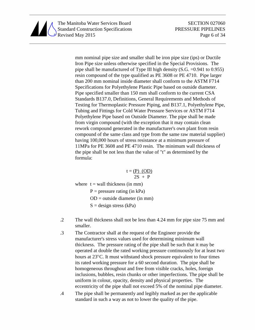
mm nominal pipe size and smaller shall be iron pipe size (ips) or Ductile Iron Pipe size unless otherwise specified in the Special Provisions. The pipe shall be manufactured of Type III high density (S.G. =0.941 to 0.955) resin compound of the type qualified as PE 3608 or PE 4710. Pipe larger than 200 mm nominal inside diameter shall conform to the ASTM F714 Specifications for Polyethylene Plastic Pipe based on outside diameter. Pipe specified smaller than 150 mm shall conform to the current CSA Standards B137.0, Definitions, General Requirements and Methods of Testing for Thermoplastic Pressure Piping, and B137.1, Polyethylene Pipe, Tubing and Fittings for Cold Water Pressure Services or ASTM F714 Polyethylene Pipe based on Outside Diameter. The pipe shall be made from virgin compound (with the exception that it may contain clean rework compound generated in the manufacturer's own plant from resin compound of the same class and type from the same raw material supplier) having 100,000 hours of stress resistance at a minimum pressure of 11MPa for PE 3608 and PE 4710 resin. The minimum wall thickness of the pipe shall be not less than the value of "t" as determined by the formula:
t = (P) (OD)
where t = wall thickness (in mm)
2S + P
P = pressure rating (in kPa) OD = outside diameter (in mm) S = design stress (kPa)
.2 The wall thickness shall not be less than 4.24 mm for pipe size 75 mm and smaller.
.3 The Contractor shall at the request of the Engineer provide the manufacturer's stress values used for determining minimum wall thickness. The pressure rating of the pipe shall be such that it may be operated at double the rated working pressure continuously for at least two hours at 23°C. It must withstand shock pressure equivalent to four times its rated working pressure for a 60 second duration. The pipe shall be homogeneous throughout and free from visible cracks, holes, foreign inclusions, bubbles, resin chunks or other imperfections. The pipe shall be uniform in colour, opacity, density and physical properties. The eccentricity of the pipe shall not exceed 5% of the nominal pipe diameter.
.4 The pipe shall be permanently and legibly marked as per the applicable standard in such a way as not to lower the quality of the pipe.
The Manitoba Water Services Board SECTION 027060 Standard Construction Specifications PRESSURE PIPELINES Revised May 2015 Page 7 of 34
.5 High Density Polyethylene pipe identification shall be placed on each length of pipe and shall include pipe size, manufacturer’s trademark or name, date of manufacture, series or DR rating, Canadian Standards Association, NSF International Certification or Water Quality Association (WQA) complete with certification trademark logo and the CSA;ASTM specification to which the pipe is certified. Certification of polyethylene pipe using NSF shall be to both NSF 61 and NSF 14 requirements. Certifiers must be accredited by the Standards Council of Canada (SCC) and by the American National Standards Institute (ANSI).
.6 Pipeline flange connection materials shall consist of a polyethylene stub end, an epoxy coated ductile iron or all stainless steel back-up ring drilled in accordance with the current AWWA Standard C110, Standard for Gray-Iron and Ductile Iron Fittings, a reinforced rubber gasket and all stainless steel nuts, bolts and washers. Pipe lengths for 150 mm and larger shall not exceed 12 m (40 ft.).
2.2 APPURTENANCES
Unless otherwise specified in Section 01001, Special Provisions, appurtenances shall be one of the following;
.1 PVC APPURTENANCES PVC appurtenances shall be used only in conjunction with PVC pipe. The appurtenances shall be manufactured in accordance with the same specifications as the PVC series or class pipe, and shall be of the same, or better, series or class as the pipe with which the fittings are used. PVC appurtenances shall be injection moulded for watermains, pipelines or forcemains 300 mm diameter or less.
.2 POLYETHYLENE APPURTENANCES PE appurtenances shall be used only in conjunction with PE pipe. The appurtenances shall be manufactured in accordance with the same specifications as the PE pipe, and shall be of the same equivalent series rating as the pipe with which the appurtenances are used. PE appurtenances shall be injection moulded for watermains, pipelines, or forcemains 300 mm diameter or less. Fabricated appurtenances must be FRP reinforced.
High Density Polyethylene Electrofusion Appurtenances shall be manufactured in compliance with ASTM F-1055 standard for electrofusion type polyethylene fittings for controlled outside diameter polyethylene pipe and tubing. Fittings shall be tested in compliance with ASTM D-2513 and ASTM F-1055. Resin shall be PE 3608 or PE 4710 virgin material that complies with ASTM D-1248 and ASTM D-3350. The fittings shall comply with NSF Standard 61 Plastic Pipe Institute (PPI) rating. Electrofusion fittings shall be rated for a maximum
The Manitoba Water Services Board SECTION 027060 Standard Construction Specifications PRESSURE PIPELINES Revised May 2015 Page 8 of 34
operating pressure of 165 psi. Fittings shall be manufactured with an integral identification resistor that automatically sets the fusion time on the Electrofusion Processor.
.3 CAST IRON APPURTENANCES Cast iron appurtenances shall be manufactured in accordance with the current AWWA Standard C110, Standard for Gray Iron and Ductile Iron Fittings. The appurtenances shall be suitable for 1,000 kPa service.
.4 JOINTS The joints shall be as follows:
.1 Bell and spigot push-on type with appropriate rubber gasket when used with PVC.
.2 Bell and spigot mechanical joint type with cast iron gland, all stainless steel nuts, bolts and washers, and the appropriate rubber gasket when used with PVC.
.3 Flanged with appropriate full face rubber gasket epoxy coated ductile iron back-up ring and all stainless steel nuts and bolts when used with polyethylene pipe.
.4 Thermal butt fusion, socket fusion in accordance with the pipe manufacturer's recommendations and using equipment approved by the manufacturer for joining polyethylene pipe
2.3 GASKETS AND LUBRICANTS
.1 Gaskets and lubricant used to join pipes and to join pipes and appurtenances shall be of a type compatible with the particular pipe or appurtenance being used. Oil and gasoline resistant gaskets are generally not required but if, during construction, the Engineer determines that the soil has been contaminated by petroleum and petroleum by-products, oil and gasoline resistant gaskets shall be used on all pipe installed within, and extending 100 metres beyond the outermost limit of, the contamination zone.
2.4 GATE VALVES
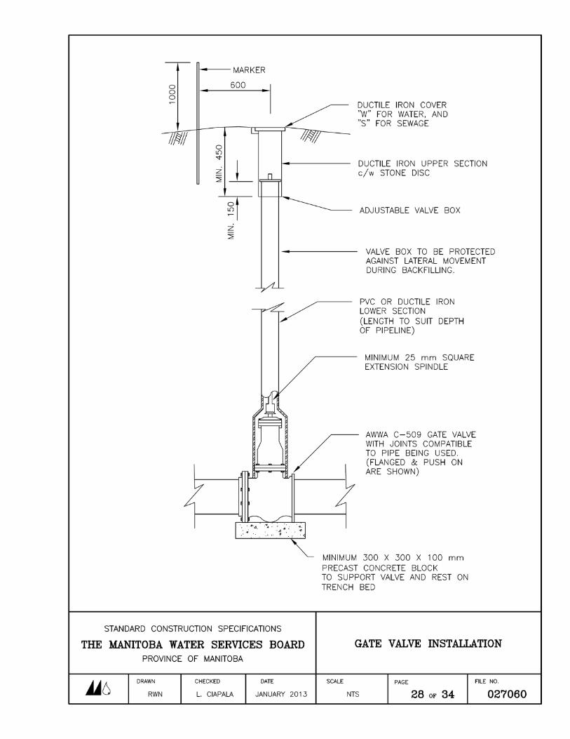
.1 Gate valves shall conform to the current AWWA C509 Standard for Resilient Seated Gate Valves and shall be suitable for 1,000 kPa service. The valves shall have an epoxy coated cast iron body with Buna-N encapsulated rubber disc trim. Gate valve stem seals shall be O-Ring type. The valve shall be complete with a counter-clockwise opening non-rising spindle. The joints shall be of the same type as the pipe to which the valve is joined (see Clause 2.2.3). Each gate valve shall be complete with a valve box, including an extension spindle with a 50 mm
The Manitoba Water Services Board SECTION 027060 Standard Construction Specifications PRESSURE PIPELINES Revised May 2015 Page 9 of 34
square operating nut, stone disc, and metal valve box cover and gate valve marker post (see gate valve installation detail page 28 of 34). The box and extension spindle shall be adjustable to suit the depth of bury specified for the pipe, plus or minus 0.3 metres.
2.5 HYDRANTS
.1 Hydrants supplied for watermain distribution fire protection purposes shall conform to the current AWWA Standard C502, for Dry-Barrel Fire Hydrants, and shall be approved by the Underwriter's Laboratory of Canada.
.2 The hydrant bonnet shall be of "dry-top" design such that the water is prevented from reaching the operating mechanism when the hydrant is discharging water. The hydrant shall have a means of lubricating the operating mechanism.
.3 The hydrant main valve shall be compression-type closing with water pressure. The diameter of the main valve shall be not less than 112 mm. The main valve shall open when the operating nut is turned counter-clockwise. The main valve and main valve seat shall be removable as a unit by turning the valve stem counter-clockwise at body level after removing the bonnet. The hydrant barrel shall be a minimum 175 mm inside diameter.
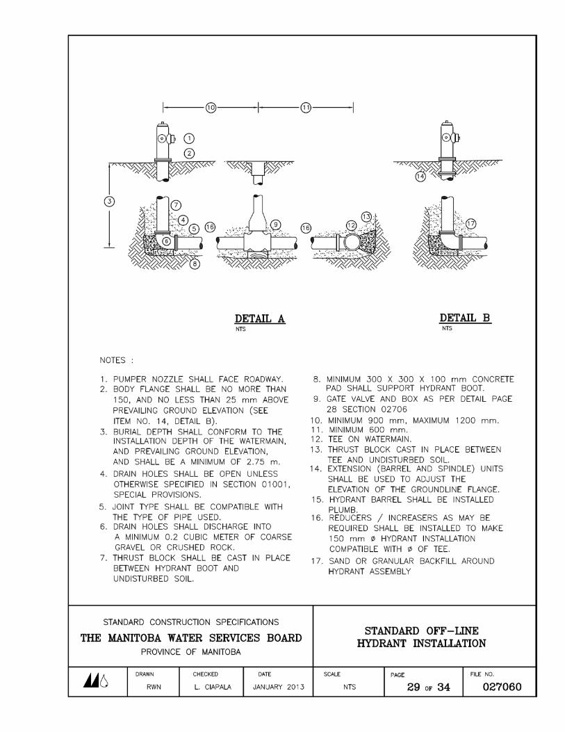
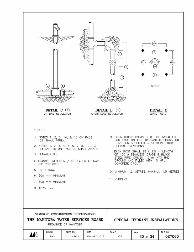
.4 Hydrants installed "off-line" shall be suitable for 150 mm nom. i.d. off-line service. The type of joint shall be as specified in Clause 2.2 of this Section. Hydrants shall be complete with a tee for installation on the pipeline or watermain. Refer to details on page 30 of this Section.
.5 Hydrants shall be supplied with drain holes (unless otherwise specified in Section 01001 of the Special Provisions), such that the hydrant barrel above the main drains dry when the main valve of the hydrant is closed. The hydrant drain holes shall be capable of being unplugged by removal of the hydrant internals (without having to excavate around the hydrant). Hydrant drain sumps (when required) for drainage shall be filled with no less than 0.2 cubic metres of crushed rock or coarse gravel.
.6 Hydrants shall be complete with two hose nozzles and one pumper nozzle. The centre line of any nozzle shall be not less than 400 mm nor more than 550 mm above the groundline. Hose nozzles shall have a nom. i.d. of 63.5 mm. Pumper nozzles shall have a nom. i.d. of 100 mm. Nozzles shall be complete with threaded caps attached by steel cable or chains to the hydrant body. The cap threads shall conform to the WCU (Western Canadian Underwriters) Standard, 0.234 threads per mm (6 per inch). The caps shall be complete with nuts to facilitate removal from the body.
The Manitoba Water Services Board SECTION 027060 Standard Construction Specifications PRESSURE PIPELINES Revised May 2015 Page 10 of 34
.7 The main valve operating nut extending beyond the bonnet and the nozzle cap nuts shall conform to the WCU Standard, a 5-sided nut fitting inside a 38 mm diameter circle.
.8 Hydrants shall have an easily repairable ("break-away") frangible section centred no more than 100 mm above the groundline. The design shall be such that when the hydrant body is struck, the impact breaks the frangible section of the barrel and of the valve stem. The manufacturer shall have available a repair kit consisting of the parts required to reconnect the body and valve stem to the lower barrel.
.9 The hydrant boot (elbow at base of hydrant) shall have a flat bottom and flat rear surface. The boot shall have a flange connection to the hydrant barrel and the flanges shall be bolted by means of all stainless steel nuts and bolts. All hydrants shall be installed complete with hydrant support blocks 300 mm x 300 mm x 100 mm size or precast concrete.
.10 The hydrant body shall be painted chrome yellow or Chinese red or as specified in Section 01001, Special Provisions. The bonnet and nozzle caps shall be painted black or silver.
.11 The hydrant body shall display the following marks:
.1 "AWWA"
.2 "ULC"
.3 manufacturer's name and model designation
.4 size of the main valve (nom. i.d.)
.5 date of casting (year)
.6 direction of turning operating nut to operate main valve
.7 groundline
.12 All hydrants shall be installed complete with hydrant support blocks 300 x 300 x 100 mm size or precast concrete block. Hydrant drain sumps shall be filled with no less than 0.2 cubic metres of crushed rock or coarse gravel. Hydrant drain sumps for post hydrants shall be a minimum of 0.1 cubic metres.
2.6 ACCESSORIES
.1 Accessories (i.e.; adaptors and couplings) required to join two different types of pipe shall be of type compatible with the pipes being used and installed in
The Manitoba Water Services Board SECTION 027060 Standard Construction Specifications PRESSURE PIPELINES Revised May 2015 Page 11 of 34
accordance with the manufacturer's recommendations, and shall be subject to the approval of the Engineer.
2.7 REPAIR CLAMPS (WRAP AROUND)
.1 Repair clamps used to make transition connections (or repairs, as directed by the Engineer) shall be wrap around "O" style suitable for 1000 kPa service.
.2 All metal parts and welds shall be type 304 stainless steel which has been fully passivated. Bolt shanks shall be forged flat to resist bending. Bolt threads shall be rolled-type, lubricated by an anti-galling compound. Nuts, bolts and washers shall be all stainless steel and shall be connected to turn independently without separating.
.3 The rubber gasket shall have tapered ends, a gridded surface and stainless steel armors. Gaskets shall be made of a synthetic equivalent to natural rubber.
.4 Clamps for all pipe with a nom. i.d. of 250 mm and less shall have a minimum of one row of no less than three bolts. Clamps for 300 mm and 350 mm nom. i.d. pipe shall have a minimum of two rows of no less than three bolts. Clamps for 400 mm nom. i.d. pipe and larger shall have three rows of no less than four bolts. Clamp lengths shall be no less than two times the nominal inside diameter of the pipe on which the clamp is to be installed.
2.8 METAL BODY COUPLINGS (COMPRESSION)
.1 Metal body-type couplings used to make transition connections shall be suitable for 1000 kPa service.
.2 The centre ring and end plates shall be fabricated of cast ductile iron (ASTM type A536) and shall be epoxy or nylon coated.
.3 Gaskets shall be fabricated of virgin rubber (ASTM type D2000, SBR) compounded for cold water service.
.4 Nuts, bolts and washers shall be all stainless steel with plastic thread protector caps.
.5 The couplings shall be supplied complete with threaded zinc anode bolt caps for corrosion projection.
The Manitoba Water Services Board SECTION 027060 Standard Construction Specifications PRESSURE PIPELINES Revised May 2015 Page 12 of 34
2.9 CONCRETE
.1 Concrete used for thrust blocks and grouting shall have a 28 day compressive strength of no less than 15 MPa. Cement used in concrete shall be sulphate resistant, meeting the current CSA Standard A 23.1 Type 50 or HS Portland Cement. Water used for concrete shall be clean and free from oil, acid, alkali, organic matter or other deleterious substances and shall be equal to potable (drinking) water in physical and chemical properties.
2.10 SUPPORT BLOCKS
.1 Precast concrete blocks used to support gate valves and hydrants shall be manufactured using sulphate resistant cement Type 50.
2.11 PRE-INSULATED PIPE AND FITTING INSULATION
.1 Insulation of pipe and fittings shall consist of closed cell rigid urethane foam, having a "K" (thermal conductivity) factor of 0.032 kJ/hr/m2/o
2.12 PRESSURE PIPELINE INSULATON (SHALLOW BURY)
C/mm, bonded by adhesive water repellent rubber sealant to a high density polyethylene outer sheath. Insulation collars with heat shrink sleeves shall be used at joints. Minimum insulation thickness shall be 50 mm unless otherwise specified in Section 01001, Special Provisions.
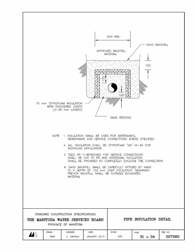
.1 In areas of shallow trench it shall be necessary to provide insulation over the top and sides of the pipe. The required insulation shall conform to current CAN/ULC S701 or CGSB-51-GP-20M type 4 rigid polystyrene foam HI-40 (blue in colour) as manufactured by DOW chemical or approved equal with a compression strength of 275 kPa. A typical pipe insulation detail is shown on page 31 of this Section. In the case of two pipes insulated in a common trench the insulation shall envelop both pipes.
2.13 ENCASEMENT PIPE
.1 Encasement pipe used in Highway or Provincial Road Crossings shall conform to the plans or as specified in Section 01001, Special Provisions. Encasement pipe used in highway crossings shall be at least 100 mm in diameter larger than PVC carrier pipe and 50 mm in diameter larger than polyethylene carrier pipe. Encasement pipe for Highway or Provincial Road Crossings shall be PVC SDR 26 or High Density Polyethylene DR 17.
.2 Encasement pipe used in Railway Crossings shall be ASTM A53 Grade B steel pipe with a minimum wall thickness of 7.6 mm, minimum yield strength of 242
The Manitoba Water Services Board SECTION 027060 Standard Construction Specifications PRESSURE PIPELINES Revised May 2015 Page 13 of 34
MPa (35,000 psi) (see Plans for details). (The Contractor may use a 50 mm larger encasement for HDPE pipe with O.D. less than 150 mm and 100 mm larger encasement for pipes larger than150 mm O.D.)
Part 3 Execution
3.1 DEPTH OF BURIAL
.1 WATERMAINS, LOW PRESSURE SEWERMAINS, AND SEWAGE FORCEMAINS The pipe shall be laid to the grade and alignment staked out on the ground by the Engineer. If no specific grades are given or shown on the Plans, the pipe shall be laid at such a depth below the ground surface that the pipe is provided with an earth cover of no less than 2.75 m above the top of the pipe for pipe installed in a town, city or village.
.2 RURAL WATER PIPELINES Minimum depth of burial for all rural water pipelines measured from normal ground elevation to the top of the pipe shall be 2.4 metres. Pipelines placed beneath roadways and driveways shall have a minimum depth of burial of 3.0 metres. Where the depth of burial is less than 2.4 m (3.0 m below roadways), the pipe shall be insulated in a manner approved by the Engineer or in accordance with Clause 2.13 of this Section.
3.2 SITE PREPARATION
.1 Where construction takes place on cultivated agricultural land, the Contractor may be required to strip or blade up to 150 mm of topsoil in the area affected by construction along the proposed pipeline route. Topsoil stripping will not be required in areas where the pipe is installed with a chain trencher or plough. The engineer shall designate and approve those areas, which shall be stripped. The topsoil shall be replaced following backfilling operations.
.2 Construction operations may require stripping or blading up to 100 mm topsoil in municipal ditches if these are cultivated and used for cropping. The Engineer shall designate and approve those areas, which shall be stripped. The topsoil shall be replaced following backfilling operations.
.3 Where construction takes place in Highway and Provincial Road ditches, stripping and blading topsoil in the area affected by construction along the proposed pipeline route. The Engineer shall designate and approve those areas which shall be stripped. The topsoil shall be replaced following backfilling operations. If
The Manitoba Water Services Board SECTION 027060 Standard Construction Specifications PRESSURE PIPELINES Revised May 2015 Page 14 of 34
less than 50 mm of topsoil exists in the Provincial Trunk Highway or Provincial road ditches, the Engineer may deem stripping to be impracticable. Topsoil removal and replacement including seeding in Highway/Provincial Road R.O.W.’s shall be incidental to the work.
3.3 EXCAVATION BEDDING AND BACKFILL
.1 This portion of the work shall be undertaken in accordance with, Section 022180, "Pipeline Excavation, Bedding and Backfill".
3.4 CLEANING
.1 Prior to installation, the interior and joining surfaces of all pipes, accessories, and appurtenances shall be cleaned of dirt and foreign material and wiped dry.
3.5 PUSH-ON JOINTS
.1 Pipe with push-on type bell and spigot joints (PVC) shall be laid with the bell end toward the direction of laying unless otherwise directed by the Engineer. The lubricant recommended by the pipe manufacturer shall be applied to the spigot end only. The spigot end shall be inserted into the bell end of the previously laid pipe to the stop mark on the pipe, such that a secure joint is obtained.
3.6 FUSION WELDED AND FLANGED JOINTS
.1 Lengths of high density (Type 3) polyethylene pipe shall be joined to each other by means of thermal butt fusion in accordance with the manufacturer's recommendations using a machine approved by the pipe manufacturer. Lengths of pipe shall be fused together alongside the trench prior to laying the pipe.
.2 After a suitable number of lengths of pipe have been joined, the pipe shall be lowered into the trench. Connections shall be made to gate valves, hydrants, or to existing flanged fittings by means of flanges. A polyethylene stub end, with an epoxy coated ductile iron or all stainless steel backup ring, shall be fused onto the pipeline. The backup ring shall be fastened with all stainless steel nuts, bolts and washers onto the fitting complete with an approved rubber gasket.
3.7 PRE-INSULATED PIPE AND FITTINGS
.1 Pipe and fitting insulation shall be factory installed. Insulation collars and heat shrink sleeves shall be installed at joints by the Contractor in accordance with the manufacturer's recommendations. All portions of pipe designated as "insulated" shall be fully insulated, and jacketed, without gaps, to the satisfaction of the
The Manitoba Water Services Board SECTION 027060 Standard Construction Specifications PRESSURE PIPELINES Revised May 2015 Page 15 of 34
Engineer. Where heat tracing is installed, the insulation shall be cut back 200 mm on one end of each section of the pipe joint and 450 mm on the other joint location. The heat trace channel sections shall be jointed with compression-type couplings or by socket fusion or as recommended by the manufacturer.
3.8 TUNNELLING (DIRECTIONAL DRILLING/BORING)
.1 HIGHWAYS, PROVINCIAL ROAD, AND RAILWAY CROSSINGS Pipe installation under all highways under the jurisdiction of the Manitoba Infrastructure and Transportation shall be by means of tunnelling and the installation of encasement pipe in accordance with Section 027070, "Highway Railway, Roadway and Utility Crossings". The Contractor may be allowed to open cut the crossing provided that he obtains prior approval and the co-operation of the Manitoba Infrastructure and Transportation. The Contractor shall be responsible for all costs associated with such work including total site restoration to the satisfaction of the Manitoba Infrastructure and Transportation.
Pipe installation under all railways, Right of Ways, under the jurisdiction of a Railway Authority shall be by means of tunnelling in accordance with Section 027070. The Contractor shall be responsible for all costs associated with such work including total site restoration to the satisfaction of the Railway Authority. A steel encasement pipe will be required for the Railway Crossings in accordance with Transport Canada’s General Order E-10 and the Railway Authority, and as shown on the plans.
.2 DIKES AND WATERWAYS Waterway (River, Creek, and Provincial Drain) Crossings shall be tunnelled where there is standing water. Where tunnelling is not possible or where there is no standing water, the waterway may be open cut and rip rap and transition material shall be placed at the bottom of the channel to prevent erosion. Tunnelling or rip rap is not required for municipal drains. If the waterway is open cut, the banks shall have the topsoil stripped and replaced and shall be re-seeded with restoration to original condition or better.
Dikes shall be tunnelled at the discretion of the Engineer. Where tunnelling is not possible, open cut trenches through the dikes shall be mechanically compacted at the time of backfilling. Backfill material shall be compacted in layers of not more than 300 mm. If open cut, dikes shall have the topsoil stripped and replaced and shall be re-seeded (see Section 27080; River Crossings).
Where the pipe is to be installed by means of tunnelling rather than by open cut trenching, the tunnel shall be of a diameter large enough to enable the pipes to be pushed through (except in the case of polyethylene, which may be pulled through)
The Manitoba Water Services Board SECTION 027060 Standard Construction Specifications PRESSURE PIPELINES Revised May 2015 Page 16 of 34
without interference or obstruction. For PVC pipe, the pits at either end of any tunnel shall be of adequate length to allow each pipe length to be lowered in parallel to the tunnel and joined to the pipe previously installed; the bell, coupling or flange of the previously installed pipe shall extend clear of the tunnel opening and be completely exposed to facilitate joining. The pipe lengths shall be securely joined in accordance with Clauses 3.5 and 3.6 of this Section, whichever is applicable. For polyethylene pipe, the pipe lengths shall be joined (by thermal butt fusion, above the pit) to a pointed nose cone, or mesh sock to which a cable is attached. The pointed nose cone or mesh sock shall be drawn through the tunnel, after which the nose cone or mesh sock shall be removed from the pipe.
3.9 CUTTING OF PIPE
.1 Where required, lengths of pipe shall be cut to the required size to facilitate joining pipe and appurtenances. Pipe shall be cut square with a fine toothed hand saw, power saw, or hack saw, but not with a chain saw. Cut ends of PVC pipe shall be bevelled to the appropriate outside diameter with a fine file to duplicate the factory bevel on the spigot end of the pipe. Cut ends of polyethylene pipe shall be smoothed to ensure that the face is at a right angle (90O
3.10 PIPE TO APPURTENANCES
) to the axis of the pipe.
.1 Pipe shall be joined to appurtenances in a manner approved for the type of pipe being installed (ie; push-on bell and spigot, coupler, mechanical, restraint, flanged) and in accordance with Clauses 3.5 and 3.6 of this Section.
3.11 THRUST BLOCKS
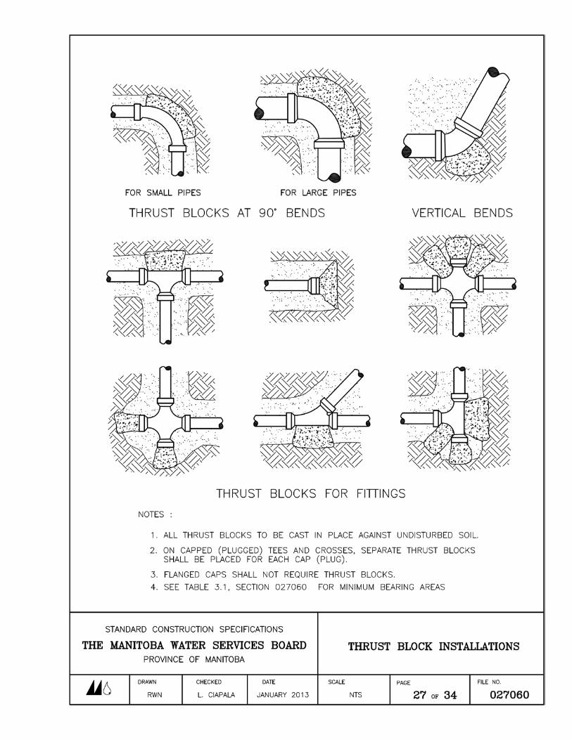
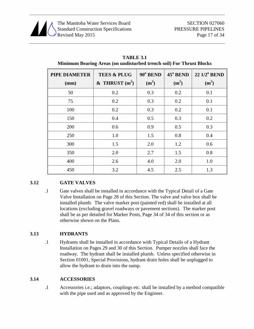
.1 Concrete thrust blocks shall be installed on all pipelines, forcemains, pressure sewer and watermains at crosses, tees, elbows, reducers, caps and hydrants in accordance with the Typical Detail of Thrust Block Installations on Page 27 of this Section. The minimum bearing areas (upon undisturbed trench soil) for thrust blocks shall be as outlined in Table 3.1.
The Manitoba Water Services Board SECTION 027060 Standard Construction Specifications PRESSURE PIPELINES Revised May 2015 Page 17 of 34
TABLE 3.1 Minimum Bearing Areas (on undisturbed trench soil) For Thrust Blocks
PIPE DIAMETER
(mm)
TEES & PLUG
& THRUST (m2
90
)
o
(m
BEND 2
45
)
o
(m
BEND 2
22 1/2
)
o
(m
BEND 2
50
)
0.2 0.3 0.2 0.1
75 0.2 0.3 0.2 0.1
100 0.2 0.3 0.2 0.1
150 0.4 0.5 0.3 0.2
200 0.6 0.9 0.5 0.3
250 1.0 1.5 0.8 0.4
300 1.5 2.0 1.2 0.6
350 2.0 2.7 1.5 0.8
400 2.6 4.0 2.0 1.0
450 3.2 4.5 2.5 1.3
3.12 GATE VALVES
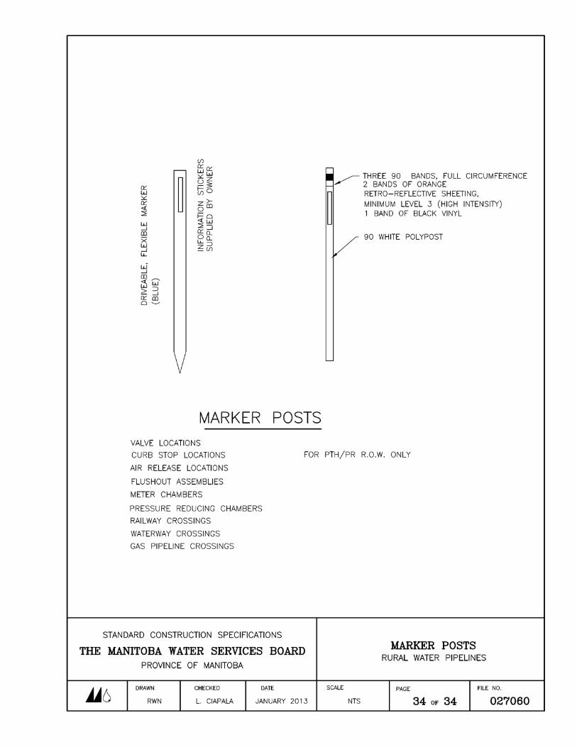
.1 Gate valves shall be installed in accordance with the Typical Detail of a Gate Valve Installation on Page 28 of this Section. The valve and valve box shall be installed plumb. The valve marker post (painted red) shall be installed at all locations (excluding gravel roadways or pavement sections). The marker post shall be as per detailed for Marker Posts, Page 34 of 34 of this section or as otherwise shown on the Plans.
3.13 HYDRANTS
.1 Hydrants shall be installed in accordance with Typical Details of a Hydrant Installation on Pages 29 and 30 of this Section. Pumper nozzles shall face the roadway. The hydrant shall be installed plumb. Unless specified otherwise in Section 01001, Special Provisions, hydrant drain holes shall be unplugged to allow the hydrant to drain into the sump.
3.14 ACCESSORIES
.1 Accessories i.e.; adaptors, couplings etc. shall be installed by a method compatible with the pipe used and as approved by the Engineer.
The Manitoba Water Services Board SECTION 027060 Standard Construction Specifications PRESSURE PIPELINES Revised May 2015 Page 18 of 34
3.15 TEMPORARY PLUGS
.1 During prolonged pauses in pipe laying, and always overnight, any open ends of the pipe shall be properly plugged with a cap compatible with the type of pipe being installed so as to prevent entry of foreign material into the pipe.
3.16 MARKER POSTS
.1 Marker posts shall be installed as indicated on the plans with affixed Owner supplied signs at the following locations:
.1 Gate valve installations
.2 Flushout installations
.3 Air release installations
.4 Utility pipeline crossings
.5 Provincial Road and PTH crossings
.6 Railway crossings
.7 Gas and oil pipeline crossings
.8 Waterway and drain crossings
.9 Curb Stops
3.17 PROHIBITION OF USE AS DRAIN
.1 Under no circumstances shall the trench or the pipeline be used as a drain.
3.18 CONNECTIONS The Contractor shall make connections at prearranged times and prearranged durations subject to approval by the Engineer. Such time and duration shall be kept to minimize disruption of existing services.
.1 CONNECTION TO EXISTING CAPPED PIPELINE GATE VALVE, OR FLUSHOUT The Contractor shall close existing gate valves as required to take the existing pipe out of service. The Contractor shall excavate carefully to the end of the existing pipe or valve so as not to damage it. The Contractor shall be responsible for repairing, at his own expense, any damage caused by him to the existing pipe or valve. When the pipe or valve end is exposed and cleaned, the Contractor shall remove the thrust block on the existing pipe. The new pipe shall be connected to the existing pipe or valve in the manner specified herein or as approved by the Engineer.
.2 CONNECTION TO EXISTING PIPE WITH NEW TEE The Contractor shall close existing gate valves as required, to take the existing
The Manitoba Water Services Board SECTION 027060 Standard Construction Specifications PRESSURE PIPELINES Revised May 2015 Page 19 of 34
pipe out of service. The Contractor shall excavate carefully to the point on the existing pipe into which the new tee is to be installed. The Contractor shall be responsible for repairing, at his own expense, any damage caused by him to the existing pipe. The Contractor shall, when the pipe is exposed and cleaned, make two cuts by the method specified in Clause 3.9 of this Section. The cut section of the existing pipe shall be removed such that the tee may be installed. After the ends of the existing pipe are trimmed (either bevelled or squared as required), these ends may be joined to the tee in accordance with Clause 3.10 of this Section. Stainless steel repair clamps, metal body couplers, PVC slip couplers, or thermal butt fusion for HDPE pipe shall be employed as required to reconnect the pipe to the new tee. The new tee shall be bedded, secured with a concrete thrust block, and backfilled in accordance with Section 022180; Pipeline Excavation, Bedding and Backfill.
.3 CONNECTION TO EXISTING MANHOLE An opening shall be provided in the manhole to permit installation of the pipe at the required elevation. The manhole base benching shall be removed by means of jack hammering, and a new benching constructed, with a semi-circular shaped channel formed to permit smooth flows through manhole. The remaining bottom of the manhole shall be benched to the bottom channel at a 10 to 1 slope. The interior and exterior of the manhole shall be sealed water tight with grout. The pipe passing through the wall of the manhole shall be coated with epoxy and sand to provide a bond when grouted to the manhole wall.
.4 CONNECTION TO LIFT STATION The pipe shall be connected to the lift station as shown on the Plans and in accordance with Section 027030; Sewers and Section 027290; Sewage Pumping Stations, or as directed by the Engineer.
.5 CONNECTION TO EXISTING WATERMAIN CROSS OR TEE The Contractor shall close existing gate valves as required to take the existing pipe out of service. The Contractor shall excavate carefully to the end of the existing pipe so as not to damage it. The Contractor shall be responsible for repairing, at his own expense, any damage caused by him to the existing pipe(s). The Contractor shall remove the portion of the old pipe to be renewed from the end of the cross or tee and replace with the required new watermain to form a complete joint. The Contractor shall install all necessary pipe, clamps, adaptors, reducers, etc., to execute the work.
.6 CONNECTION TO WETWELL An opening shall be cut in the sewage treatment plant or pumping station wetwell as shown on the Plans and in accordance with Clause 3.11 of Section 027030
The Manitoba Water Services Board SECTION 027060 Standard Construction Specifications PRESSURE PIPELINES Revised May 2015 Page 20 of 34
“Sewers” or as directed by the Engineer. The pipe shall be inserted, grouted or installed using a sleeve with link seal as shown on the Plans or directed by the Engineer.
.7 CONNECTION TO WASTEWATER STABILIZATION POND The pipe shall be installed at the grade alignment and elevation shown on the Plans or as directed by the Engineer. The excavation through the dyke and through the pond floor
3.19 HYDROSTATIC TESTING
.1 The Contractor shall perform hydrostatic tests on all portions of the completed pipe under the direct supervision of the Engineer. The length of pipe to be tested shall not exceed the distance between neighbouring valves, except where neighbouring valves are less than 150 m apart or where approved otherwise by Engineer.
.2 All equipment and labour necessary to perform the hydrostatic testing, including water for testing, shall be supplied by the Contractor at his own expense. The equipment shall include all required hoses, pumps, water, make-up tanks and gauges. The Contractor shall utilize test gauges with a minimum ½ % accuracy; minimum 100 mm dial face with increments maximum of 7 kPa (1psi) and calibrated with an upper scale no more than 350 kPa above test pressure. The Engineer shall have the right to use his own gauge and to calibrate the Contractor's equipment.
.3 Hydrostatic testing shall not commence until at least 72 hours after the installation of the last thrust block on the line to be tested.
.4 Prior to hydrostatic testing, the line(s) shall be filled slowly with water (which shall be potable in the case of watermains and water pipelines) and all air shall be expelled from the line. If permanent air vents, flushouts or hydrants are not located at all high points, the Contractor shall install main (corporation) stops at such points in order to allow the air to be expelled as the pipe fills with water. The Contractor to use an approved residential water meter to measure how much water is being pumped into the watermain.
.5 The line shall be tested for pressure and for leakage. Unless otherwise specified in Section 01001, Special Provisions, the test pressure for both types of tests shall be 700 kPa except in the case of watermains, which shall be tested at 1000 kPa.
(For PVC Pipe Only)
The Manitoba Water Services Board SECTION 027060 Standard Construction Specifications PRESSURE PIPELINES Revised May 2015 Page 21 of 34
The tests shall not commence until a minimum of 24 hours has passed since the pipe was filled with water.
.1 PRESSURE TEST The duration of each test shall be no less than two hours. At the end of the first hour, the pressure shall be boosted to its initial value. At the end of the second hour, the pressure shall be checked. The drop in pressure shall not exceed 2%. If the pressure drop is in excess of this, the Contractor shall find the leak, correct it, and repeat the test until the line can show a pressure drop of less than 2% in one hour.
As an alternative to the above, a pressure drop of no more than 15% over a 12 hour period shall be acceptable.
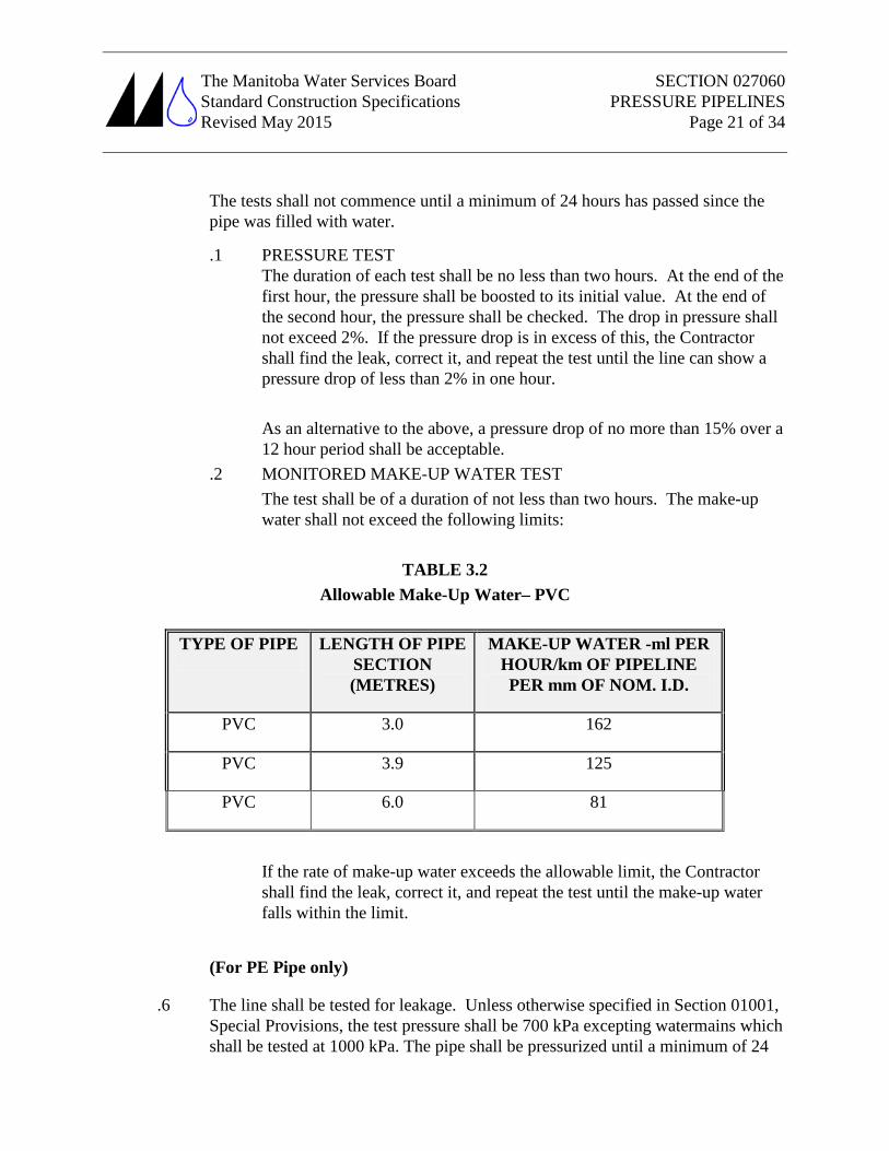
.2 MONITORED MAKE-UP WATER TEST The test shall be of a duration of not less than two hours. The make-up water shall not exceed the following limits:
TABLE 3.2
Allowable Make-Up Water– PVC
TYPE OF PIPE LENGTH OF PIPE SECTION (METRES)
MAKE-UP WATER -ml PER HOUR/km OF PIPELINE PER mm OF NOM. I.D.
PVC 3.0 162
PVC 3.9 125
PVC 6.0 81
If the rate of make-up water exceeds the allowable limit, the Contractor shall find the leak, correct it, and repeat the test until the make-up water falls within the limit.
(For PE Pipe only)
.6 The line shall be tested for leakage. Unless otherwise specified in Section 01001, Special Provisions, the test pressure shall be 700 kPa excepting watermains which shall be tested at 1000 kPa. The pipe shall be pressurized until a minimum of 24
The Manitoba Water Services Board SECTION 027060 Standard Construction Specifications PRESSURE PIPELINES Revised May 2015 Page 22 of 34
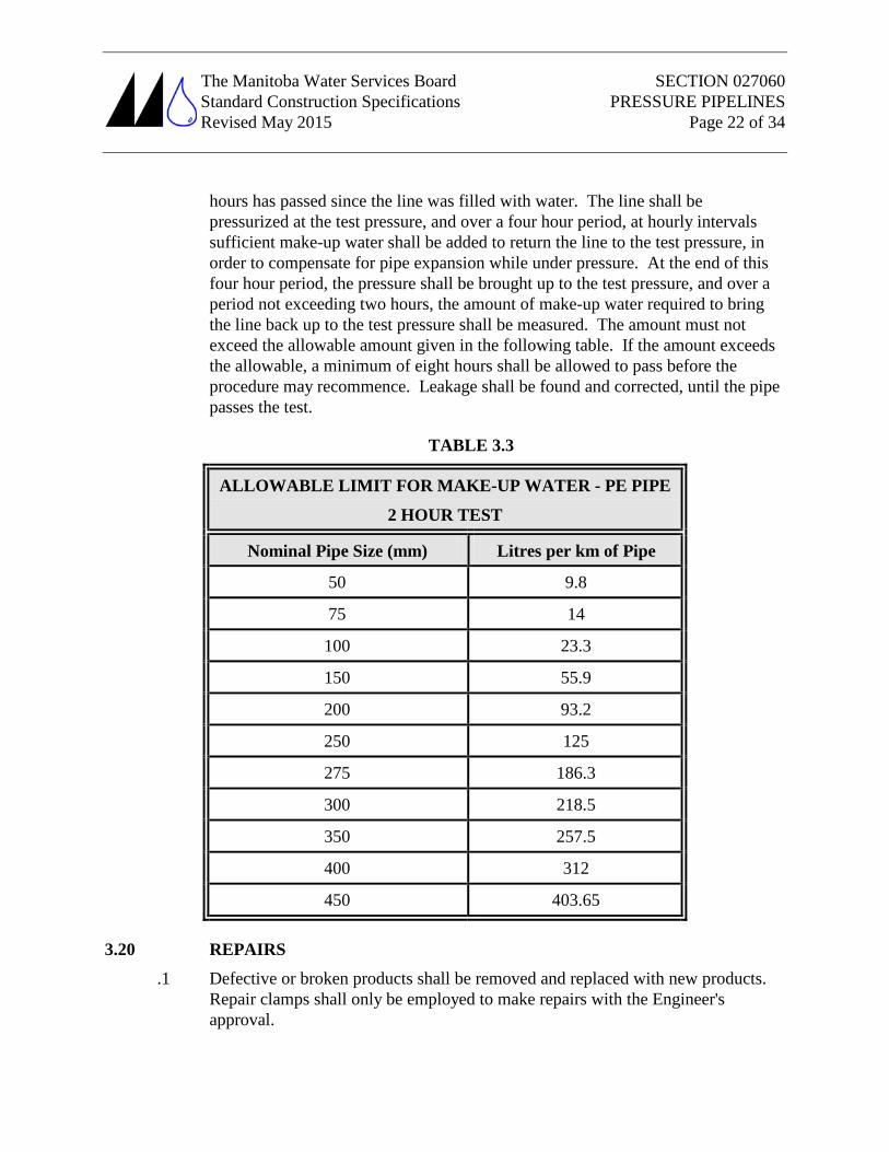
hours has passed since the line was filled with water. The line shall be pressurized at the test pressure, and over a four hour period, at hourly intervals sufficient make-up water shall be added to return the line to the test pressure, in order to compensate for pipe expansion while under pressure. At the end of this four hour period, the pressure shall be brought up to the test pressure, and over a period not exceeding two hours, the amount of make-up water required to bring the line back up to the test pressure shall be measured. The amount must not exceed the allowable amount given in the following table. If the amount exceeds the allowable, a minimum of eight hours shall be allowed to pass before the procedure may recommence. Leakage shall be found and corrected, until the pipe passes the test.
TABLE 3.3
ALLOWABLE LIMIT FOR MAKE-UP WATER - PE PIPE
2 HOUR TEST
Nominal Pipe Size (mm) Litres per km of Pipe
50 9.8
75 14
100 23.3
150 55.9
200 93.2
250 125
275 186.3
300 218.5
350 257.5
400 312
450 403.65
3.20 REPAIRS
.1 Defective or broken products shall be removed and replaced with new products. Repair clamps shall only be employed to make repairs with the Engineer's approval.
The Manitoba Water Services Board SECTION 027060 Standard Construction Specifications PRESSURE PIPELINES Revised May 2015 Page 23 of 34
3.21 DISINFECTION
Water pipelines intended to convey potable water and all watermains shall be disinfected as follows:
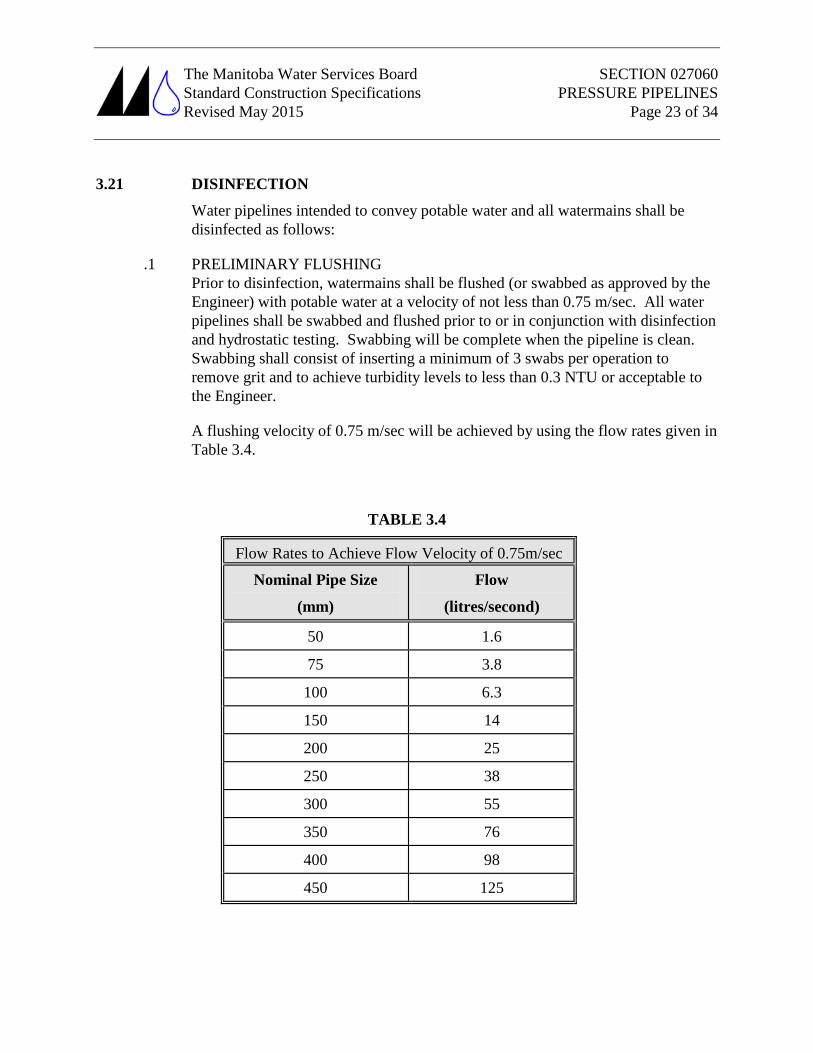
.1 PRELIMINARY FLUSHING Prior to disinfection, watermains shall be flushed (or swabbed as approved by the Engineer) with potable water at a velocity of not less than 0.75 m/sec. All water pipelines shall be swabbed and flushed prior to or in conjunction with disinfection and hydrostatic testing. Swabbing will be complete when the pipeline is clean. Swabbing shall consist of inserting a minimum of 3 swabs per operation to remove grit and to achieve turbidity levels to less than 0.3 NTU or acceptable to the Engineer.
A flushing velocity of 0.75 m/sec will be achieved by using the flow rates given in Table 3.4.
TABLE 3.4
Flow Rates to Achieve Flow Velocity of 0.75m/sec
Nominal Pipe Size
(mm)
Flow
(litres/second)
50 1.6
75 3.8
100 6.3
150 14
200 25
250 38
300 55
350 76
400 98
450 125
The Manitoba Water Services Board SECTION 027060 Standard Construction Specifications PRESSURE PIPELINES Revised May 2015 Page 24 of 34
.2 FORM OF CHLORINE Acceptable forms of chlorine which may be used to prepare disinfecting solutions include calcium hypochlorite granules (powder), calcium hypochlorite tablets, and sodium hypochlorite solutions (liquid).
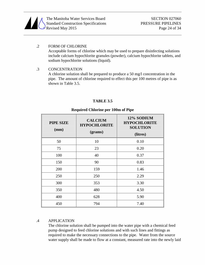
.3 CONCENTRATION A chlorine solution shall be prepared to produce a 50 mg/l concentration in the pipe. The amount of chlorine required to effect this per 100 metres of pipe is as shown in Table 3.5.
TABLE 3.5
Required Chlorine per 100m of Pipe
PIPE SIZE
(mm)
CALCIUM HYPOCHLORITE
(grams)
12% SODIUM HYPOCHLORITE
SOLUTION
(litres)
50 10 0.10
75 23 0.20
100 40 0.37
150 90 0.83
200 159 1.46
250 250 2.29
300 353 3.30
350 480 4.50
400 628 5.90
450 794 7.40
.4 APPLICATION The chlorine solution shall be pumped into the water pipe with a chemical feed pump designed to feed chlorine solutions and with such lines and fittings as required to make the necessary connections to the pipe. Water from the source water supply shall be made to flow at a constant, measured rate into the newly laid
The Manitoba Water Services Board SECTION 027060 Standard Construction Specifications PRESSURE PIPELINES Revised May 2015 Page 25 of 34
pipe. The water shall receive a dose of chlorine solution fed at a constant, measured rate. The two rates shall be proportioned so that the chlorine dosage is maintained at a minimum of 50 mg/l. The Engineer shall take such samples as he deems necessary in order to determine the chlorine concentration.
During the application of chlorine, gate valves on adjacent sections of the distribution system shall be closed to prevent the treatment dosage from flowing into any existing lines or back into the source water supply. Chlorine application shall continue until the entire newly constructed pipe is filled with chlorine solution. The chlorinated water shall be retained in the pipe for 24 hours. During this time, all valves on the lines shall be operated to allow penetration of the chlorine solution into the interior parts of each valve. At the end of the 24 hour period, the chlorine residual as measured by the Engineer shall not be less than 15 mg/l.
.5 FINAL FLUSHING - After the 24 hour retention period, the heavily chlorinated water shall be flushed from the pipe until the chlorine concentration in the flushed water does not exceed that of the water from the source supply. The Engineer shall take samples to determine the free chlorine residual.
.6 BACTERIOLOGICAL TESTS - After final flushing, the Engineer shall take samples from the end of the pipeline or watermain which shall be subjected to bacteriological analysis by a public health laboratory.
.7 REPETITION OF PROCEDURE - If initial disinfection fails to produce satisfactory samples, the disinfection process shall be repeated until satisfactory samples are obtained.
.8 DISPOSAL OF FLUSHING WATER – Water from pipeline disinfection shall not be released to surface water bodies until free chlorine concentrations are below 0.1 mg/l. Releases of chlorinated water at higher chlorine concentrations may be made to vegetated land or dry waterways, provided that chlorine concentrations are less than 0.1 mg/l before the released water reaches any body of surface water.
3.22 COMPLETION
.1 When the pipelines or watermains have been tested and disinfected to the satisfaction of the Engineer, the Contractor shall place the pipeline or watermains into service by opening all gate valves (curb stops shall remain closed after service line flushing & water meter installation) as required. The Contractor shall provide all initial meter readings and meter serial numbers and locations to the Owner prior to putting the watermains into service.
The Manitoba Water Services Board SECTION 027060 Standard Construction Specifications PRESSURE PIPELINES Revised May 2015 Page 26 of 34
3.23 CLEAN-UP
.1 The contractor shall remove all equipment, surplus and waste materials from the site. Trenches shall be left in a neatly bladed condition. The pipeline trench shall be left mounded sufficiently to allow for the future settlement and consolidation of the excavated materials used to backfill the trench, unless otherwise requested by the Engineer and as per Section 24850; Topsoil and Finish Grading.
.2 All construction areas including ditches shall be restored and maintained to original grade and conditions. All boulders, surface debris, etc. shall be removed from site and the construction area shall be neatly graded smooth without surface protrusions or holes.
.3 The Contractor shall re-seed any ditches or water crossings complete with erosion measured as required affected by construction as may be required by Manitoba Infrastructure & Transportation or the local Conservation District or as directed by the Engineer.
.4 The Contractor shall restore and clean up construction areas as soon as possible (weather permitting) after pipeline and service line installation including restoration and repair of fences.