Embed Size (px)
Citation preview

Par
tne
rin
g f
or
Pe
rfe
ct P
acka
gin
g S
olu
tio
ns
Refractory Parts for the Glassmaking Industry

Table of Contents
Click the Chapter name below to navigate:
Orifice Rings & Gaskets ........................................1
Plungers ..............................................................31
Tubes ...................................................................41
Spouts .................................................................51
Spout Assemblies................................................61
Stirrers & Rotor Segments ..................................85
Insulation, Cements & Hard Bricks......................91
Forehearth Maintenance Items ...........................97
Glasshouse Crucibles & Accessories.................105
Technical References .........................................113
Material Safety Data Sheet (MSDS) ..................121
Note:Pages 40, 50, 84, 90, 96, and 112were intentionally left blank.

Emhart Glass Refractories for Glassmaking
Emhart Glass refractories are formulated from high
purity, special oxide raw materials and manufactured
with the properties necessary for the success of each
specific glass making operation. In our laboratory,
manufacturing, and quality operations, we bring
together people, processes, and products to meet your
needs. Our refractory craftsmen– most with at least a
decade of experience– are the heart of our operation.
They are supported by engineering and R&D
professionals who emphasize innovative product
development and individual customer solutions.

Quality Engineered Feeder and Refractory Expendables
Emhart Glass has earned a reputation for unsurpassed quality in
refractories. As a flexible, well-staffed fabricator of premium refractory
compositions, our goal is to service the individual requirements of each
customer, no matter what type of glass they manufacture. What’s
more, we can provide a level of customized service normally
unavailable from other refractories manufacturers.
We’re a division of the global Emhart Glass enterprise, so we can
leverage the continuing evolution in glass making technology from the
industry leader. For example, the patented 555 Feeder Mechanism
includes a self-centering tube holder and orifice ring pans with
engineered refractory rings for consistent quality and efficient
production. Emhart Glass offers a full range of standard refractory
shapes, and also manufactures unusual, complex, and small quantity
shapes to the same exacting tolerances.
The Industry’s Widest Range of Glass Refractory Expendable
Compositions
Emhart Glass continues to advance
the state of the art in gob forming
technology. One way we do this is by
providing the industry’s widest range
of glass refractory expendable
compositions. Our bonded compo -
sitions include Alumina Silicates, AZS,
Zircon, and Fused Silica. We offer the
full range of shapes in industry
standard compositions including 333, 315, 311, 338, and 345. For
applications demanding customized compositions, our unrivaled
research and development capabilities enable us to devise
formulations to achieve specific customer objectives.
Glass Containers
Flat Glass
Television/Monitor Glass
Fiberglass
Emhart Refractories for Glassmaking
Time-Honored Craftsmanship, World-Class Innovation
Emhart Glass supplies precision-crafted refractory products designed for a wide range of applications:
Art Glass
Hand Glass
Tableware
Pressware
Quality Driven
Since 1927, Emhart Glass has been developing and manufacturing
high quality refractories for the glass container industry. The
Owensville plant has manufactured refractories since it was purchased
in 1980 from the Laclede Christy Refractory Company. Laclede Christy
was founded in 1844 and built a strong reputation as a refractory
maker. Before becoming a refractory plant in 1970, the Owensville
plant had specialised in the production of glass pot refractories. Once
Emhart Glass purchased the plant, the company closed its other
refractory operations and concentrated all production in Owensville–
a setup that has been maintained to this day.
Emhart Glass understands that the basis of superior glass
conditioning for all areas of the glass making industry is high quality
refractories. Their use in forehearth and feeder mechanisms play
crucial roles in the formation and conditioning of the glass prior to
being formed into finished products. All Emhart refractories are
formulated from the highest quality raw materials and designed to
achieve predictable density and resistance to erosion and corrosion.
Precise PC monitoring of batching and kiln firing ensure the highest
quality performance and service life.
Customer Focused
Our customer service team responds rapidly to provide
knowledgeable assistance to help our customers eliminate downtime
and maximize production efficiency. Emhart Glass continues to grow
by serving the glass making industry with time-honored
craftsmanship, world-class innovation, and service to customers.

Forehearth and Feeder Products
High quality refractories are crucial to proper conditioning of molten
glass. Emhart Glass forehearth refractory components are designed
for long life with predictable heat loss characteristics and resistance
to thermal shock, erosion, and corrosion. The range of forehearth
components includes both substructure and superstructure. We also
manufacture distributor shapes, alcoves, doglegs, and colorant
sections. Emhart Glass also manufacturers a full range of feeder
refractories, including spouts, tubes, plungers, and orifice rings.
Feeder refractories are available in a variety of materials to address
each customer’s individual needs.
Exclusive Refractory Products for the Handglass Industry
The ability to match our proprietary mixes to our customers’ melt and
firing needs has enabled Emhart Glass Owensville to serve a wide
spectrum of glass industries. Today, Emhart Glass is a leading
manufacturer and supplier of Glass House Crucibles, used exclusively
in hand glass shops throughout the world. This highly specialized
product line demands meticulous craftsmanship. We manufacture a
wide variety of shapes and sizes, ranging from one pound glass
capacity open crucibles to closed pots with 500 pound glass capacity.
Emhart Glass also offers a complete line of refractory accessories
designed specifically for the hand glass industry.
Removal of a refractory furnace liner from the mold.Filling orifice ring molds. Finish work on green burner blocks prior to
entering the drying room.

Plungers
Tubes
Spouts
Orifice R
ings
& Gaskets
Spout
Assem
blies
Stirrers &Rotor Seg
ments
Insulation,Cem
ents &Hard
Bricks
ForehearthMaintenance Item
s
GlasshouseCrucib
les& Accessories
TechnicalReferences
MSD
SMaterial SafetyData Sheet
USA, OWENSVILLE, MOPlant number for technical assistance Telephone +1 (573) 437 2132Ordering +1 800 243 0048
Orifice Rings & Gaskets
Excellent Thermal Shock Resistance, Accurate Shapes
The complex and precise shape of orifice rings places
special demands on the refractory material. In service,
orifice rings must be able to deliver good thermal shock
resistance and corrosion resistance to preserve their
accurate shape.
Emhart Glass’ 311 and 345 materials contain 91% and
83% Al2O3, respectively. Both are high purity materials,
specifically designed for the fabrication of complex
shapes. They are designed with a close grained structure
that provides the necessary corrosion resistance to
complement their thermal shock resistance. They have
proven an excellent choice for shops with frequent job
changes. In applications where extended orifice ring life
is desired, Emhart Glass 314 and 315, bonded AZS
materials containing 20% ZrO2, provide excellent
performance
Click the Section Tabs at right to navigate by section
or click the Menu below to navigate to pages in this section.
1

2
Orifice RingsMaterial Data
311 314
ZrO2 -- 20Al2O3 91 11SiO2 9 69Density (g/cc) 2.6 3.0Porosity (%) 23 24MOR (MPa) 16.5 15.9Type Pressed Pressed
Additional materials available upon request. Pleasecontact your nearest Emhart Representative forassistance.
All data is subject to reasonable deviations and not to be usedfor specification purposes.
For special applications, alternative refractory materialsare available. Please contact your nearest Emhart Glassrepresentative.
Refractory Part Numbers
123-4567- 3XXEmhart GlassPart Number
Emhart GlassMaterial

5⁄16 8 144-15340-3XX 11⁄32 9 144-15341-3XX 3⁄8 10 144-15342-3XX 13⁄32 10.3 144-15343-3XX 7⁄16 11 144-15344-3XX 15⁄32 12 144-15345-3XX 1⁄2 13 144-15346-3XX 17⁄32 13.5 144-15347-3XX 9⁄16 14 144-15348-3XX Carbon Steel 2” 19⁄32 15 144-15349-3XX 144-1333 (51 mm) 5⁄8 16 144-15350-3XX 21⁄32 16.7 144-15351-3XX Stainless Steel 11⁄16 17 144-15352-3XX 144-14363 23⁄32 18 144-15353-3XX 3⁄4 19 144-15354-3XX 25⁄32 20 144-15355-3XX 13⁄16 21 144-15356-3XX 27⁄32 21.4 144-15357-3XX 7⁄8 22 144-15358-3XX 29⁄32 23 144-15359-3XX 15⁄16 24 144-15360-3XX 31⁄32 24.6 144-15361-3XX
1 25 144-15362-3XX
11⁄16 27 144-15363-3XX
11⁄8 29 144-15364-3XX
13⁄16 30 144-15365-3XX
11⁄4 32 144-15366-3XX
15⁄16 33 144-15367-3XX
13⁄8 35 144-15368-3XX Carbon Steel 3”
17⁄16 37 144-15369-3XX 144-1337 (76 mm)
11⁄2 38 144-15370-3XX
19⁄16 40 144-15371-3XX Stainless Steel
15⁄8 41 144-15372-3XX 144-14365
111⁄16 43 144-15373-3XX
13⁄4 44 144-15374-3XX
113⁄16 46 144-15375-3XX
17⁄8 48 144-15376-3XX
115⁄16 49 144-15377-3XX
5” Spout Single Gob Orifice Rings Orifice Diameter Ø Ring Holder Boss
in. mm Part # Part # Diameter
KS-144-15565
KS-144-15566
3

2 51 144-15378-3XX
21⁄16 52 144-15379-3XX
21⁄8 54 144-15380-3XX
23⁄16 56 144-15381-3XX
21⁄4 57 144-15382-3XX
25⁄16 59 144-15383-3XX
23⁄8 60 144-15384-3XX Carbon Steel 4”
27⁄16 62 144-15385-3XX 144-1341 (102 mm)
21⁄2 64 144-15386-3XX
29⁄16 65 144-15387-3XX Stainless Steel
25⁄8 67 144-15388-3XX 144-14367
211⁄16 68 144-15389-3XX
23⁄4 70 144-15390-3XX
213⁄16 71 144-15391-3XX
27⁄8 73 144-15392-3XX
215⁄16 75 144-15393-3XX
3 76 144-15394-3XX
31⁄16 78 144-15395-3XX
31⁄8 79 144-15396-3XX
33⁄16 81 144-15397-3XX
31⁄4 83 144-15398-3XX
35⁄16 84 144-15399-3XX
33⁄8 86 144-15400-3XX
37⁄16 87 144-15401-3XX
31⁄2 89 144-15402-3XX
39⁄16 90 144-15403-3XX
35⁄8 92 144-15404-3XX Carbon Steel 51⁄2”
311⁄16 94 144-15405-3XX 144-10330 (140 mm)
33⁄4 95 144-15406-3XX
313⁄16 97 144-15407-3XX Stainless Steel
37⁄8 98 144-15408-3XX 144-14370
315⁄16 100 144-15409-3XX
4 102 144-15410-3XX
41⁄16 103 144-15411-3XX
41⁄8 105 144-15412-3XX
43⁄16 106 144-15413-3XX
41⁄4 108 144-15414-3XX
45⁄16 110 144-15415-3XX
43⁄8 111 144-15416-3XX
47⁄16 113 144-15417-3XX
41⁄2 114 144-15418-3XX
5” Spout Single Gob Orifice Rings
Orifice Diameter Ø Ring Holder Boss in. mm Part # Part # Diameter
KS-144-15567
KS-144-15568
4

5
3⁄8 10 81-3848-3XX7⁄16 11 81-3849-3XX15⁄32 12 81-3850-3XX1⁄2 13 81-3851-3XX Carbon Steel 11⁄4”17⁄32 13.5 81-3852-3XX 81-309-1 (32 mm)9⁄16 14 81-3853-3XX19⁄32 15 81-3854-3XX Stainless Steel 5⁄8 16 81-3855-3XX 81-297-1 21⁄32 16.7 81-3856-3XX11⁄16 17 81-3857-3XX
23⁄32 18 81-3858-3XX3⁄4 19 81-3859-3XX25⁄32 20 81-3860-3XX13⁄16 21 81-3861-3XX Carbon Steel 11⁄2” 27⁄32 21.4 81-3862-3XX 81-309-2 (38 mm)7⁄8 22 81-3863-3XX29⁄32 23 81-3864-3XX Stainless Steel15⁄16 24 81-3865-3XX 81-297-231⁄32 24.6 81-3866-3XX
1 25 81-3867-3XX
11⁄16 27 81-3868-3XX Carbon Steel
11⁄8 29 81-3869-3XX 81-309-3 13⁄4”
13⁄16 30 81-3870-3XX Stainless Steel (44 mm)
11⁄4 32 81-3871-3XX 81-297-3
15⁄16 33 81-3872-3XX Carbon Steel
13⁄8 35 81-3873-3XX 81-309-4
17⁄16 37 81-3874-3XX 2”
11⁄2 38 81-3875-3XX Stainless Steel (51 mm)
19⁄16 40 81-3876-3XX 81-297-4
15⁄8 41 81-3877-3XX
111⁄16 43 81-3878-3XX Carbon Steel 23⁄16”
13⁄4 44 81-3879-3XX 81-309-5 (56 mm)
113⁄16 46 81-3880-3XX Stainless Steel
81-297-5
17⁄8 48 81-3881-3XX Carbon Steel
115⁄16 49 81-3882-3XX 81-309-6 23⁄8”
2 51 81-3883-3XX Stainless Steel (60 mm)
21⁄16 52 81-3884-3XX 81-297-6
5” Spout Double Gob Orifice Rings3” Center Distance Orifice Diameter Ø Ring Holder Boss
in. mm Part # Part # Diameter
KS-81-4463
KS-81-4468
KS-81-4464
KS-81-4465
KS-81-4466
KS-81-4467

6
23⁄32 18 81-3044-3XX3⁄4 19 81-3045-3XX25⁄32 20 81-3084-3XX13⁄16 21 81-3046-3XX 11⁄2”27⁄32 21.4 81-3085-3XX (38 mm)7⁄8 22 81-3047-3XX29⁄32 23 81-3086-3XX15⁄16 24 81-3048-3XX31⁄32 24.6 81-3087-3XX
1 25 81-3049-3XX
11⁄8 29 501-9223-3XX
11⁄16 27 501-9272-3XX
11⁄8 29 501-9138-3XX
15⁄16 33 81-2919-3XX
13⁄8 35 81-2845-3XX 2”
17⁄16 37 81-2846-3XX (51 mm)
11⁄2 38 81-2622-3XX
19⁄16 40 81-2847-3XX
15⁄8 41 81-2848-3XX
13⁄4 44 81-2850-3XX
11⁄16 27 81-3050-3XX
11⁄8 29 81-3051-3XX 13⁄4”
13⁄16 30 81-2921-3XX (44 mm)
11⁄4 32 81-2920-3XX
5” Spout Double Gob Orifice Rings - Cooling Slots27⁄8” Center Distance Orifice Diameter Ø Boss
in. mm Part # Diameter
KS501-9679
KS501-9701
KS501-9697
5” Spout Double Gob Orifice Rings3” Center Distance Orifice Diameter Ø Ring Holder Boss
in. mm Part # Part # Diameter
21⁄8 54 81-3885-3XX Carbon Steel 27⁄16”
81-309-7 (62 mm)
23⁄16 56 81-3886-3XX Stainless Steel
81-297-7 KS-81-4469

7
1⁄2 13 58-3012-3XX9⁄16 14 58-3013-3XX5⁄8 16 58-3014-3XX 194-87-1 213⁄16”11⁄16 17 58-3015-3XX (71 mm) 3⁄4 19 58-3016-3XX13⁄16 21 58-3017-3XX
7⁄8 22 58-3018-3XX15⁄16 24 58-3019-3XX
1 25 58-3020-3XX 194-87-2 3”
11⁄16 27 58-3021-3XX (76 mm)
11⁄8 29 58-3022-3XX
13⁄16 30 58-3023-3XX
11⁄4 32 58-2662-3XX
15⁄16 33 58-3041-3XX
13⁄8 35 58-2663-3XX 194-87-3 31⁄4”
17⁄16 37 58-2949-3XX (83 mm)
11⁄2 38 58-2664-3XX
19⁄16 40 58-2950-3XX
15⁄8 41 58-2665-3XX
111⁄16 43 58-2951-3XX
13⁄4 44 58-2666-3XX 194-87-4 31⁄2”
113⁄16 46 58-2952-3XX (89 mm)
17⁄8 48 58-2667-3XX
115⁄16 49 58-2953-3XX
2 51 58-2525-3XX
21⁄16 52 58-2954-3XX
21⁄8 54 58-2526-3XX
23⁄16 56 58-2955-3XX 194-87-5 4”
21⁄4 57 58-2527-3XX (102 mm)
25⁄16 59 58-2956-3XX
23⁄8 60 58-2528-3XX
27⁄16 62 58-3158-3XX
21⁄2 63 58-2529-3XX
29⁄16 65 58-3159-3XX
25⁄8 67 58-2530-3XX
211⁄16 68 58-3160-3XX 194-87-6 43⁄8”
23⁄4 70 58-2531-3XX (111 mm)
213⁄16 71 58-3161-3XX
27⁄8 73 58-2532-3XX
215⁄16 75 58-3162-3XX
7” Spout Single Gob Orifice RingsOrifice Diameter Ø Ring Holder Boss
in. mm Part # Part # Diameter
KS-58-3178
KS-58-3182
KS-58-3177
KS-58-3179
KS-58-3180
KS-58-3181

8
3 76 58-2533-3XX
31⁄16 78 58-3163-3XX
31⁄8 79 58-2534-3XX 194-87-7 43⁄4”
33⁄16 81 58-3164-3XX (121 mm)
31⁄4 83 58-2535-3XX
33⁄8 86 58-2536-3XX
31⁄2 89 58-2537-3XX
35⁄8 92 58-2538-3XX 194-87-8 51⁄8”
33⁄4 95 58-2539-3XX (130 mm)
37⁄8 98 58-2540-3XX
4 102 58-2541-3XX
41⁄8 105 58-2542-3XX 194-87-9 55⁄8”
41⁄4 108 58-2543-3XX (143 mm)
43⁄8 111 58-2544-3XX
41⁄2 114 58-2545-3XX
45⁄8 117 58-2546-3XX 194-87-10 61⁄16”
43⁄4 121 58-2547-3XX (154 mm)
47⁄8 124 58-2548-3XX
5 127 58-2549-3XX
51⁄8 130 58-2550-3XX 194-87-11 61⁄2”
51⁄4 133 58-2551-3XX (165 mm)
53⁄8 137 58-2552-3XX
51⁄2 140 58-2553-3XX
55⁄8 143 58-2554-3XX 194-87-12 615⁄16”
53⁄4 146 58-2555-3XX (176 mm)
57⁄8 149 58-2556-3XX
6 152 58-2557-3XX
61⁄8 156 58-2558-3XX 73⁄8”
61⁄4 159 58-2559-3XX 194-87-13 (187 mm)
63⁄8 162 58-2560-3XX
61⁄2 165 58-2561-3XX
7” Spout Single Gob Orifice Rings Orifice Diameter Ø Ring Holder Boss
in. mm Part # Part # Diameter
KS-58-3184
KS-58-3183
KS-58-3185
KS-58-3187
KS-58-3189
KS-58-3186
KS-58-3188

9
3⁄8 10 81-3815-3XX7⁄16 11 81-3816-3XX1⁄2 13 81-3817-3XX 194-141-1 11⁄4” 9⁄16 14 81-3818-3XX (32 mm)5⁄8 16 81-3819-3XX11⁄16 17 81-3820-3XX
3⁄4 19 81-3821-3XX13⁄16 21 81-3822-3XX 194-74-2 11⁄2” 7⁄8 22 81-3823-3XX (38 mm)15⁄16 24 81-3824-3XX
1 25 81-3825-3XX
11⁄16 27 81-3826-3XX
11⁄8 29 81-3827-3XX 194-74-3 13⁄4”
13⁄16 30 81-3828-3XX (44 mm)
11⁄4 32 81-3829-3XX
15⁄16 33 81-3830-3XX
13⁄8 35 81-3831-3XX
17⁄16 37 81-3832-3XX 194-74-4 2”
11⁄2 38 81-3833-3XX (51 mm)
19⁄16 40 81-3834-3XX
15⁄8 41 81-3835-3XX
111⁄16 43 81-3836-3XX 23⁄16”
13⁄4 44 81-3837-3XX 194-74-5 (56 mm)
113⁄16 46 81-3838-3XX
17⁄8 48 81-3839-3XX
115⁄16 49 81-3840-3XX 21⁄4”
2 51 81-3841-3XX 194-74-6 (57 mm)
21⁄16 52 81-3842-3XX
21⁄8 54 81-3843-3XX
7” Spout Double Gob Orifice Rings3” Center Distance Orifice Diameter Ø Ring Holder Boss
in. mm Part # Part # Diameter
KS-81-3814
KS-81-3814
KS-81-3814
KS-81-3814
KS-81-3814
KS-81-3814

10
1⁄2 13 194-5588-3XX9⁄16 14 194-5589-3XX5⁄8 16 194-5590-3XX11⁄16 17 194-5591-3XX3⁄4 19 194-5592-3XX13⁄16 21 194-5593-3XX 194-141-1 13⁄4” 7⁄8 22 194-5594-3XX (44 mm)15⁄16 24 194-5595-3XX
1 25 194-5596-3XX
11⁄16 27 194-5597-3XX
11⁄8 29 194-5598-3XX
13⁄16 30 194-5599-3XX
11⁄4 32 194-5600-3XX
15⁄16 33 194-5601-3XX
13⁄8 35 194-5602-3XX
17⁄16 37 194-5603-3XX
11⁄2 38 194-5604-3XX
19⁄16 40 194-5605-3XX
15⁄8 41 194-5606-3XX
111⁄16 43 194-5607-3XX
13⁄4 44 194-5608-3XX
113⁄16 46 194-5609-3XX
17⁄8 48 194-5610-3XX 194-141-2 3”
115⁄16 49 194-5611-3XX (76 mm)
2 51 194-5612-3XX
21⁄16 52 194-5613-3XX
21⁄8 54 194-5614-3XX
23⁄16 56 194-5615-3XX
21⁄4 57 194-5616-3XX
25⁄16 59 194-5617-3XX
23⁄8 60 194-5618-3XX
27⁄16 62 194-5619-3XX
21⁄2 64 194-5620-3XX
29⁄16 65 194-5621-3XX
25⁄8 67 194-5622-3XX
211⁄16 68 194-5623-3XX 33⁄8”
23⁄4 70 194-5624-3XX 194-141-3 (86 mm)
213⁄16 71 194-5625-3XX
27⁄8 73 194-5626-3XX
7” Spout Double Gob Orifice Rings43⁄8” Center Distance Orifice Diameter Ø Ring Holder Boss
in. mm Part # Part # Diameter
KS-194-5665
KS-194-5666
KS-194-5667

11
1⁄2 13 194-5687-3XX9⁄16 14 194-5688-3XX5⁄8 16 194-5689-3XX11⁄16 17 194-5690-3XX3⁄4 19 194-5691-3XX13⁄16 21 194-5692-3XX 194-141-1 13⁄4”7⁄8 22 194-5693-3XX (44 mm)15⁄16 24 194-5694-3XX
1 25 194-5695-3XX
11⁄16 27 194-5696-3XX
11⁄8 29 194-5697-3XX
13⁄16 30 194-5698-3XX
11⁄4 32 194-5699-3XX
15⁄16 33 194-5700-3XX
13⁄8 35 194-5701-3XX
17⁄16 37 194-5702-3XX
11⁄2 38 194-5703-3XX
19⁄16 40 194-5704-3XX
15⁄8 41 194-5705-3XX
111⁄16 43 194-5706-3XX
13⁄4 44 194-5707-3XX
113⁄16 46 194-5708-3XX
17⁄8 48 194-5709-3XX 194-141-2 3”
115⁄16 49 194-5710-3XX (76 mm)
2 51 194-5711-3XX
2 1⁄16 52 194-5712-3XX
2 1⁄8 54 194-5713-3XX
2 3⁄16 56 194-5714-3XX
21⁄4 57 194-5715-3XX
2 5⁄16 59 194-5716-3XX
2 3⁄8 60 194-5717-3XX
2 7⁄16 62 194-5718-3XX
2 1⁄2 64 194-5719-3XX
2 9⁄16 65 194-5720-3XX
2 5⁄8 67 194-5721-3XX
2 11⁄16 68 194-5722-3XX
2 3⁄4 70 194-5723-3XX 194-141-3 33⁄8”
2 13⁄16 71 194-5724-3XX (86 mm)
2 7⁄8 73 194-5725-3XX
2 15⁄16 75 194-5726-3XX
7” Spout Double Gob Orifice Rings - Solid Bridge43⁄8” Center Distance Orifice Diameter Ø Ring Holder Boss
in. mm Part # Part # Diameter
KS-501-6467
KS-501-6184
KS-501-6468

12
3⁄4 19 144-21818-3XX13⁄16 21 144-21819-3XX7⁄8 22 144-21820-3XX15⁄16 24 144-21821-3XX
1 25 144-21822-3XX
11⁄16 27 144-21823-3XX
11⁄8 29 144-21824-3XX
13⁄16 30 144-21825-3XX
11⁄4 32 144-21826-3XX
15⁄16 33 144-21827-3XX
13⁄8 35 144-21828-3XX
17⁄16 37 144-21829-3XX
11⁄2 38 144-21832-3XX
19⁄16 40 144-21833-3XX
15⁄8 41 144-21834-3XX
1⁄2 13 81-4959-3XX9⁄16 14 81-4960-3XX5⁄8 16 81-4961-3XX11⁄16 17 81-4962-3XX3⁄4 19 81-4963-3XX13⁄16 21 81-4964-3XX7⁄8 22 81-4965-3XX15⁄16 24 81-4966-3XX
1 25 81-4967-3XX
11⁄16 27 81-4968-3XX
11⁄8 29 81-4969-3XX
13⁄16 30 81-4970-3XX
11⁄4 32 81-4971-3XX
15⁄16 33 81-4972-3XX
13⁄8 35 81-4973-3XX
17⁄16 37 81-4974-3XX
11⁄2 38 81-4975-3XX
19⁄16 40 81-4976-3XX
15⁄8 41 81-4977-3XX
13⁄4 44 81-4978-3XX
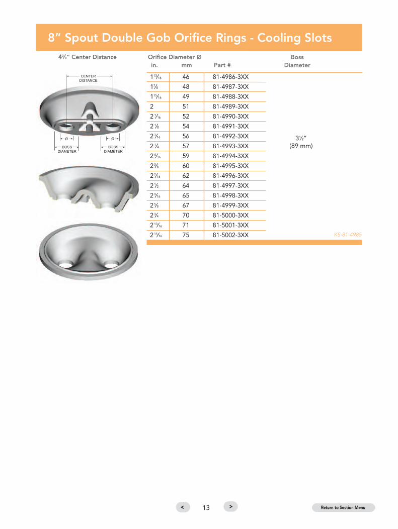
8” Spout Double Gob Orifice Rings - Cooling Slots43⁄8” Center Distance Orifice Diameter Ø Boss
in. mm Part # Diameter
KS-144-21817
21⁄4”(57 mm)
Raised Boss
21⁄4”(57 mm)
KS-81-4983
13
113⁄16 46 81-4986-3XX
17⁄8 48 81-4987-3XX
115⁄16 49 81-4988-3XX
2 51 81-4989-3XX
2 1⁄16 52 81-4990-3XX
2 1⁄8 54 81-4991-3XX
23⁄16 56 81-4992-3XX
2 1⁄4 57 81-4993-3XX
2 5⁄16 59 81-4994-3XX
23⁄8 60 81-4995-3XX
27⁄16 62 81-4996-3XX
21⁄2 64 81-4997-3XX
29⁄16 65 81-4998-3XX
25⁄8 67 81-4999-3XX
23⁄4 70 81-5000-3XX
213⁄16 71 81-5001-3XX
215⁄16 75 81-5002-3XX
8” Spout Double Gob Orifice Rings - Cooling Slots43⁄8” Center Distance Orifice Diameter Ø Boss
in. mm Part # Diameter
KS-81-4985
31⁄2”(89 mm)

1414
3⁄8 10 144-15093-3XX7⁄16 11 144-15094-3XX1⁄2 13 144-15095-3XX9⁄16 14 144-15096-3XX5⁄8 16 144-15097-3XX 144-21568-1 11⁄2”11⁄16 17 144-15098-3XX (38 mm)3⁄4 19 144-15099-3XX13⁄16 21 144-15100-3XX7⁄8 22 144-15101-3XX
15⁄16 24 81-6331-3XX
1 25 81-6332-3XX
11⁄16 27 81-6333-3XX
11⁄8 29 81-6334-3XX
13⁄16 30 81-6335-3XX 144-21568-2
11⁄4 32 81-6336-3XX
15⁄16 33 81-6337-3XX
13⁄8 35 81-6338-3XX
17⁄16 37 81-6339-3XX
11⁄2 38 81-6329-3XX
8” Spout Triple Gob Orifice Rings - Cooling Slots3” Center Distance Orifice Diameter Ø Ring Holder Boss
in. mm Part # Part # Diameter
KS-144-15092
2”(51 mm)Wide x8”
(203 mm)Longwith
CoolingSlots
(Oval Boss)KS-81-6330

15
1 25 501-6344-3XX
11⁄8 29 501-9069-3XX
13⁄16 30 501-9068-3XX
11⁄4 32 501-6345-3XX
13⁄8 35 503-5815-3XX
17⁄16 37 503-9304-3XX
11⁄2 38 503-5816-3XX
15⁄8 41 503-5817-3XX
13⁄4 44 503-5662-3XX
113⁄16 46 503-5663-3XX
17⁄8 48 503-5664-3XX
115⁄16 49 503-5665-3XX
2 51 503-5666-3XX
21⁄16 52 503-5667-3XX
2 1⁄8 54 503-5668-3XX
2 3⁄16 56 503-5669-3XX
2 1⁄4 57 503-5670-3XX
2 5⁄16 59 503-5671-3XX
2 3⁄8 60 503-5672-3XX
2 7⁄16 62 503-5673-3XX
2 1⁄2 64 503-5674-3XX
2 9⁄16 65 503-5675-3XX
25⁄8 67 503-5676-3XX
2 11⁄16 68 503-5677-3XX
2 3⁄4 70 503-5678-3XX
2 13⁄16 71 503-5679-3XX
2 7⁄8 73 503-5680-3XX
2 15⁄16 75 503-5681-3XX
3 76 503-5682-3XX
3 1⁄16 78 503-5683-3XX 555-252-2 43⁄4”
31⁄8 79 503-5684-3XX Cast Stainless (121 mm)
3 3⁄16 81 503-5685-3XX Steel
3 1⁄4 83 503-5686-3XX
3 5⁄16 84 503-5687-3XX
3 3⁄8 86 503-5688-3XX
37⁄16 87 503-5689-3XX
31⁄2 89 501-6109-3XX
3 5⁄8 92 501-9275-3XX
33⁄4 95 501-6193-3XX
4 102 501-6110-3XX
10” Spout Single Gob Orifice Rings Orifice Diameter Ø Ring Holder Boss
in. mm Part # Part # Diameter
KS-503-6388
KS-503-6989
555-252-1
Cast Stainless
Steel
4”
(102 mm)

16
7⁄8 22 501-9109-3XX
1 25 503-6574-3XX
11⁄16 27 503-6575-3XX
11⁄8 29 503-6576-3XX
13⁄16 30 503-6577-3XX
11⁄4 32 503-6578-3XX
15⁄16 33 503-6579-3XX
13⁄8 35 503-6580-3XX
17⁄16 37 503-6581-3XX
11⁄2 38 503-6582-3XX
19⁄16 40 503-6583-3XX
15⁄8 41 503-6584-3XX
111⁄16 43 503-6585-3XX
13⁄4 44 503-6586-3XX
113⁄16 46 503-6587-3XX
17⁄8 48 503-6588-3XX
115⁄16 49 503-6589-3XX 555-252-9 33⁄4”
2 51 503-6590-3XX Cast Stainless (95 mm)
21⁄16 52 503-6591-3XX Steel Wide x
21⁄8 54 503-6592-3XX 81⁄8”
23⁄16 56 503-6593-3XX (206 mm)
21⁄4 57 503-6594-3XX Long
25⁄16 59 503-6595-3XX
23⁄8 60 503-6596-3XX
27⁄16 62 503-6597-3XX
21⁄2 64 503-6598-3XX
29⁄16 65 503-6599-3XX
25⁄8 67 503-6600-3XX
211⁄16 68 503-6601-3XX
23⁄4 70 503-6602-3XX
213⁄16 71 503-6603-3XX
27⁄8 73 503-6604-3XX
215⁄16 75 503-6605-3XX
3 76 503-6606-3XX
31⁄16 78 503-6607-3XX
31⁄8 79 503-6608-3XX
31⁄4 83 503-6609-3XX
33⁄8 86 503-6610-3XX
10” Spout Double Gob Orifice Rings - Solid Bridge43⁄8” Center Distance Orifice Diameter Ø Ring Holder Boss
in. mm Part # Part # Diameter
KS-503-6573

17
7⁄8 22 501-9330-3XX
1 25 503-6255-3XX
11⁄16 27 503-6256-3XX
11⁄8 29 503-6257-3XX
13⁄16 30 503-6258-3XX
11⁄4 32 503-5766-3XX
15⁄16 33 503-5765-3XX
13⁄8 35 503-5764-3XX
17⁄16 37 503-5751-3XX
11⁄2 38 503-5750-3XX
19⁄16 40 503-5749-3XX
15⁄8 41 503-5748-3XX
111⁄16 43 503-5747-3XX
13⁄4 44 503-5746-3XX
113⁄16 46 503-5745-3XX
17⁄8 48 503-5743-3XX 555-252-6 33⁄4”
115⁄16 49 503-5742-3XX Cast Stainless (95 mm)
2 51 503-5735-3XX Steel
21⁄16 52 503-5734-3XX
21⁄8 54 503-5733-3XX
23⁄16 56 503-5732-3XX
21⁄4 57 503-5731-3XX
25⁄16 59 503-5730-3XX
23⁄8 60 503-5729-3XX
27⁄16 62 503-5728-3XX
21⁄2 64 503-5727-3XX
29⁄16 65 503-5726-3XX
25⁄8 67 503-5719-3XX
211⁄16 68 503-5720-3XX
23⁄4 70 503-5721-3XX
213⁄16 71 503-5722-3XX
27⁄8 73 503-5723-3XX
215⁄16 75 503-5724-3XX
3 76 503-5725-3XX
31⁄16 78 503-5793-3XX
31⁄8 79 503-5794-3XX
31⁄4 83 503-5795-3XX
33⁄8 86 503-5796-3XX
10” Spout Double Gob Orifice Rings - Cooling Slots43⁄8” Center Distance Orifice Diameter Ø Ring Holder Boss
in. mm Part # Part # Diameter
KS-503-6390

1818
11⁄4 32 515-6152-3XX
15⁄16 33 515-6153-3XX
13⁄8 35 515-6154-3XX
17⁄16 37 515-6155-3XX
11⁄2 38 515-6156-3XX
19⁄16 40 515-6157-3XX
15⁄8 41 515-6158-3XX
111⁄16 43 515-6159-3XX
13⁄4 44 515-5081-3XX
113⁄16 46 515-5082-3XX
17⁄8 48 515-5083-3XX
115⁄16 49 515-5084-3XX
2 51 515-5085-3XX
21⁄16 52 515-5086-3XX
21⁄8 54 515-5087-3XX
23⁄16 56 515-5088-3XX
21⁄4 57 515-5089-3XX 555-252-7 41⁄4”
25⁄16 59 515-5090-3XX Cast (108 mm)
23⁄8 60 515-5091-3XX Stainless
27⁄16 62 515-5137-3XX Steel
21⁄2 64 515-5008-3XX
29⁄16 65 515-5009-3XX
25⁄8 67 515-5010-3XX
211⁄16 68 515-5011-3XX
23⁄4 70 515-5012-3XX
213⁄16 71 515-5013-3XX
27⁄8 73 515-5014-3XX
215⁄16 75 515-5015-3XX
3 76 515-5016-3XX
31⁄16 78 515-5017-3XX
31⁄8 79 515-5018-3XX
33⁄16 81 515-5019-3XX
31⁄4 83 515-5020-3XX
35⁄16 84 515-5021-3XX
33⁄8 86 515-5022-3XX
37⁄16 87 515-5023-3XX
31⁄2 89 515-5024-3XX
39⁄16 90 515-5025-3XX
35⁄8 92 515-5026-3XX
311⁄16 94 515-5027-3XX
33⁄4 95 515-5028-3XX
10” Spout Double Gob Orifice Rings - Cooling Slots5” Center Distance Orifice Diameter Ø Ring Holder Boss
in. mm Part # Part # Diameter
KS-515-5029

19
11⁄4 32 503-5860-3XX
15⁄16 33 503-5861-3XX
13⁄8 35 503-5862-3XX
17⁄16 37 503-5863-3XX
11⁄2 38 503-5864-3XX
19⁄16 40 503-5865-3XX
15⁄8 41 503-5866-3XX
111⁄16 43 503-5867-3XX 555-252-8 25⁄8”
13⁄4 44 503-5868-3XX Cast (67 mm)
113⁄16 46 503-5869-3XX Stainless
17⁄8 48 503-5870-3XX Steel
115⁄16 49 503-5871-3XX
2 51 503-5872-3XX
21⁄16 52 503-5851-3XX
21⁄8 54 503-5852-3XX
23⁄16 56 503-5853-3XX
21⁄4 57 503-5854-3XX
10” Spout Triple Gob Orifice Rings3” Center Distance Orifice Diameter Ø Ring Holder Boss
in. mm Part # Part # Diameter
KS-503-6392
15⁄16 15⁄16 501-6438-3XX
19⁄16 19⁄16 501-6430-3XX 25⁄8”
15⁄8 15⁄8 501-6431-3XX (67 mm)
111⁄16 111⁄16 501-6432-3XX Wide
13⁄4 13⁄4 501-6433-3XX 555-252-10 x
113⁄16 113⁄16 501-6434-3XX 85⁄8”
13⁄8 13⁄8 501-6526-3XX (219 mm)
17⁄16 17⁄16 501-6527-3XX Long
115⁄16 115⁄16 501-9047-3XX
21⁄8 21⁄8 501-9141-3XX
15⁄8 19⁄16 501-6436-3XX Note: For this
19⁄16 11⁄2 501-6437-3XX group, the
13⁄4 15⁄8 501-6440-3XX dimension for
13⁄4 111⁄16 501-9000-3XX center orifice is
13⁄8 15⁄16 501-6502-3XX not the same
111⁄16 15⁄8 501-9023-3XX as dimension
113⁄16 13⁄4 501-9066-3XX for outside
17⁄8 113⁄16 501-9067-3XX orifices.
10” Spout Triple Gob Orifice Rings - Solid Bridge215⁄16” Center Distance Orifice Diameter Ø Ring Holder Boss
A (in.) B (in.) Part # Part # Diameter
KS-503-6477
KS-503-6477

20
11⁄4 32 503-6478-3XX
15⁄16 33 503-6479-3XX
13⁄8 35 503-6480-3XX
17⁄16 37 503-6481-3XX
11⁄2 38 503-6482-3XX
19⁄16 40 503-6483-3XX 25⁄8”
15⁄8 41 503-6484-3XX (67 mm)
111⁄16 43 503-6485-3XX 555-252-10 Wide
13⁄4 44 503-6486-3XX x
113⁄16 46 503-6487-3XX 85⁄8”
17⁄8 48 503-6488-3XX (219 mm)
115⁄16 49 503-6489-3XX Long
2 51 503-6490-3XX
2 1⁄16 52 503-6491-3XX
2 1⁄8 54 503-6492-3XX
2 3⁄16 56 503-6493-3XX
2 1⁄4 57 503-6494-3XX
10” Spout Triple Gob Orifice Rings - Solid Bridge3” Center Distance Orifice Diameter Ø Ring Holder Boss
in. mm Part # Part # Diameter
KS-503-6477
21⁄16 52 515-6097-3XX
21⁄8 54 515-6061-3XX
23⁄16 56 515-6060-3XX
21⁄4 57 515-6095-3XX
25⁄16 59 515-6058-3XX 515-212-1 37⁄8”
23⁄8 60 515-6057-3XX (98mm)
27⁄16 62 515-6056-3XX
21⁄2 64 515-6055-3XX
29⁄16 65 515-6054-3XX
25⁄8 67 515-6053-3XX
211⁄16 68 515-6052-3XX
23⁄4 70 515-6051-3XX
12” Double Gob Orifice Rings - Cooling Slots43⁄8” Center Distance Orifice Diameter Ø Ring Holder Boss
in. mm Part # Part # Diameter
KS-515-6050

21
111⁄16 43 515-6014-3XX
13⁄4 44 515-6013-3XX
113⁄16 46 515-6012-3XX
17⁄8 48 515-6011-3XX
115⁄16 49 515-6010-3XX
2 51 515-6009-3XX 515-211-1 31⁄8”
21⁄16 52 515-6008-3XX (79 mm)
21⁄8 54 515-6007-3XX
23⁄16 56 515-6006-3XX
21⁄4 57 515-6005-3XX
25⁄16 59 515-6004-3XX
23⁄8 60 515-6003-3XX
27⁄16 62 515-6002-3XX
21⁄2 64 515-6001-3XX
12” Triple Gob Orifice Rings - Cooling Slots43⁄8” Center Distance Orifice Diameter Ø Ring Holder Boss
in. mm Part # Part # Diameter
KS-515-6000

22
11⁄2 38 81-4800-3XX
19⁄16 40 81-4801-3XX
15⁄8 41 81-4802-3XX
111⁄16 43 81-4803-3XX
13⁄4 44 81-4804-3XX
113⁄16 46 81-4805-3XX
17⁄8 48 81-4806-3XX
115⁄16 49 81-4807-3XX
2 51 81-4808-3XX
21⁄16 52 81-4809-3XX
21⁄8 54 81-4810-3XX
23⁄16 56 81-4811-3XX
21⁄4 57 81-4812-3XX
25⁄16 59 81-4813-3XX 144-21841-1
23⁄8 60 81-4814-3XX
27⁄16 62 81-4815-3XX
21⁄2 64 81-4816-3XX
29⁄16 65 81-4817-3XX
25⁄8 67 81-4818-3XX
211⁄16 68 81-4819-3XX
23⁄4 70 81-4820-3XX
213⁄16 71 81-4821-3XX
27⁄8 73 81-4822-3XX
215⁄16 75 81-4823-3XX
3 76 81-4824-3XX
31⁄16 78 81-4825-3XX
31⁄8 79 81-4826-3XX
33⁄16 81 81-4827-3XX
31⁄4 83 81-4828-3XX
35⁄ 16 84 81-4829-3XX
81 Series - Single Gob Metering Orifice Rings
Orifice Diameter Ø in. mm Part # Ring Holder Part #
KS-81-4799

23
81 Series - Double Gob Metering Orifice Rings - 8” Metering Spout
Orifice Diameter Ø in. mm Part # Ring Holder Part #
1 25 81-4701-3XX
11⁄16 27 81-4702-3XX
11⁄8 29 81-4703-3XX
13⁄16 30 81-4704-3XX
11⁄4 32 81-4705-3XX
15⁄16 33 81-4706-3XX
13⁄8 35 81-4707-3XX
17⁄16 37 81-4708-3XX
11⁄2 38 81-4709-3XX
19⁄16 40 81-4710-3XX
15⁄8 41 81-4711-3XX 144-21839-1
111⁄16 43 81-4712-3XX
13⁄4 44 81-4713-3XX
113⁄16 46 81-4714-3XX
17⁄8 48 81-4715-3XX
115⁄16 49 81-4716-3XX
2 51 81-4717-3XX
21⁄16 52 81-4731-3XX
21⁄8 54 81-4732-3XX
23⁄16 56 81-4733-3XX
21⁄4 57 81-4734-3XX
23⁄ 8 60 81-4740-3XX
43/8" Center Distance
KS-81-4699
81 Series - Triple Gob Metering Orifice Rings - 9” Metering Spout
Orifice Diameter Ø in. mm Part # Ring Holder Part #
11⁄16 17 81-4787-3XX3⁄4 19 81-4788-3XX13⁄16 21 81-4789-3XX7⁄8 22 81-4790-3XX15⁄16 24 81-4791-3XX 144-21840-1
1 25 81-4792-3XX
11⁄16 27 81-4793-3XX
11⁄8 29 81-4794-3XX
13⁄16 30 81-4795-3XX
11⁄ 4 32 81-4796-3XX
3" Center Distance
KS-81-4786

24
503/515 Series - Single Gob Metering Orifice Rings - 10” or 11” Spout
Orifice Diameter Ø in. mm Part # Ring Holder Part #
13⁄8 35 503-6914-3XX
11⁄2 38 503-6915-3XX
19⁄16 40 503-6916-3XX
15⁄8 41 503-6917-3XX
111⁄16 43 503-6918-3XX
13⁄4 44 503-6919-3XX
113⁄16 46 503-6920-3XX
17⁄8 48 503-6921-3XX
115⁄16 49 503-6922-3XX
2 51 503-6923-3XX
21⁄16 52 503-6924-3XX
21⁄8 54 503-6925-3XX
23⁄16 56 503-6926-3XX
21⁄4 57 503-6927-3XX
25⁄16 59 503-6928-3XX
23⁄8 60 503-6929-3XX 555-252-13
27⁄16 62 503-6930-3XX
21⁄2 64 503-6931-3XX
29⁄16 65 503-6932-3XX
25⁄8 67 503-6933-3XX
211⁄16 68 503-6934-3XX
23⁄4 70 503-6935-3XX
213⁄16 71 503-6936-3XX
27⁄8 73 503-6937-3XX
215⁄16 75 503-6938-3XX
3 76 503-6939-3XX
31⁄16 78 503-6940-3XX
31⁄8 79 503-6941-3XX
33⁄16 81 503-6942-3XX
31⁄4 83 503-6943-3XX
35⁄16 84 503-6944-3XX
33⁄8 86 503-6945-3XX
37⁄16 87 503-6946-3XX KS-501-9209

25
503/515 Series - Double Gob Metering Orifice Rings - 10” or 11” Spout
Orifice Diameter Ø in. mm Part # Ring Holder Part #
1 25 503-6883-3XX
11⁄16 27 503-6884-3XX
11⁄8 29 503-6885-3XX
13⁄16 30 503-6886-3XX
11⁄4 32 503-6887-3XX
15⁄16 33 503-6888-3XX
13⁄8 35 503-6889-3XX
17⁄16 37 503-6890-3XX
11⁄2 38 503-6891-3XX
19⁄16 40 503-6892-3XX
15⁄8 41 503-6893-3XX
111⁄16 43 503-6894-3XX
13⁄4 44 503-6895-3XX
113⁄16 46 503-6896-3XX
17⁄8 48 503-6875-3XX
115⁄16 49 503-6898-3XX 555-252-12
2 51 503-6899-3XX
21⁄16 52 503-6900-3XX
21⁄8 54 503-6901-3XX
23⁄16 56 503-6902-3XX
21⁄4 57 503-6903-3XX
25⁄16 59 503-6904-3XX
23⁄8 60 503-6905-3XX
27⁄16 62 503-6906-3XX
21⁄2 64 503-6876-3XX
29⁄16 65 503-6908-3XX
25⁄8 67 503-6909-3XX
211⁄16 68 503-6910-3XX
23⁄4 70 503-6911-3XX
213⁄16 71 503-6912-3XX
27⁄8 73 503-6897-3XX
215⁄ 16 75 503-6907-3XX
43⁄8" Center Distance
KS-501-9205
26
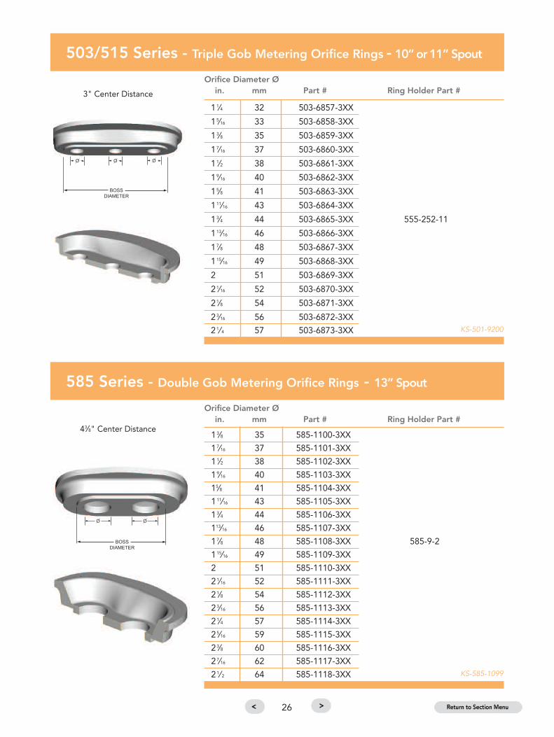
503/515 Series - Triple Gob Metering Orifice Rings - 10” or 11” Spout
Orifice Diameter Ø in. mm Part # Ring Holder Part #
11⁄4 32 503-6857-3XX
15⁄16 33 503-6858-3XX
13⁄8 35 503-6859-3XX
17⁄16 37 503-6860-3XX
11⁄2 38 503-6861-3XX
19⁄16 40 503-6862-3XX
15⁄8 41 503-6863-3XX
111⁄16 43 503-6864-3XX
13⁄4 44 503-6865-3XX 555-252-11
113⁄16 46 503-6866-3XX
17⁄8 48 503-6867-3XX
115⁄16 49 503-6868-3XX
2 51 503-6869-3XX
21⁄16 52 503-6870-3XX
21⁄8 54 503-6871-3XX
23⁄16 56 503-6872-3XX
21⁄ 4 57 503-6873-3XX
3" Center Distance
KS-501-9200
585 Series - Double Gob Metering Orifice Rings - 13” Spout
Orifice Diameter Ø in. mm Part # Ring Holder Part #
13⁄8 35 585-1100-3XX
17⁄16 37 585-1101-3XX
11⁄2 38 585-1102-3XX
19⁄16 40 585-1103-3XX
15⁄8 41 585-1104-3XX
111⁄16 43 585-1105-3XX
13⁄4 44 585-1106-3XX
113⁄16 46 585-1107-3XX
17⁄8 48 585-1108-3XX 585-9-2
115⁄16 49 585-1109-3XX
2 51 585-1110-3XX
21⁄16 52 585-1111-3XX
21⁄8 54 585-1112-3XX
23⁄16 56 585-1113-3XX
21⁄4 57 585-1114-3XX
25⁄16 59 585-1115-3XX
23⁄8 60 585-1116-3XX
27⁄16 62 585-1117-3XX
21⁄ 2 64 585-1118-3XX
43⁄8" Center Distance
KS-585-1099
27
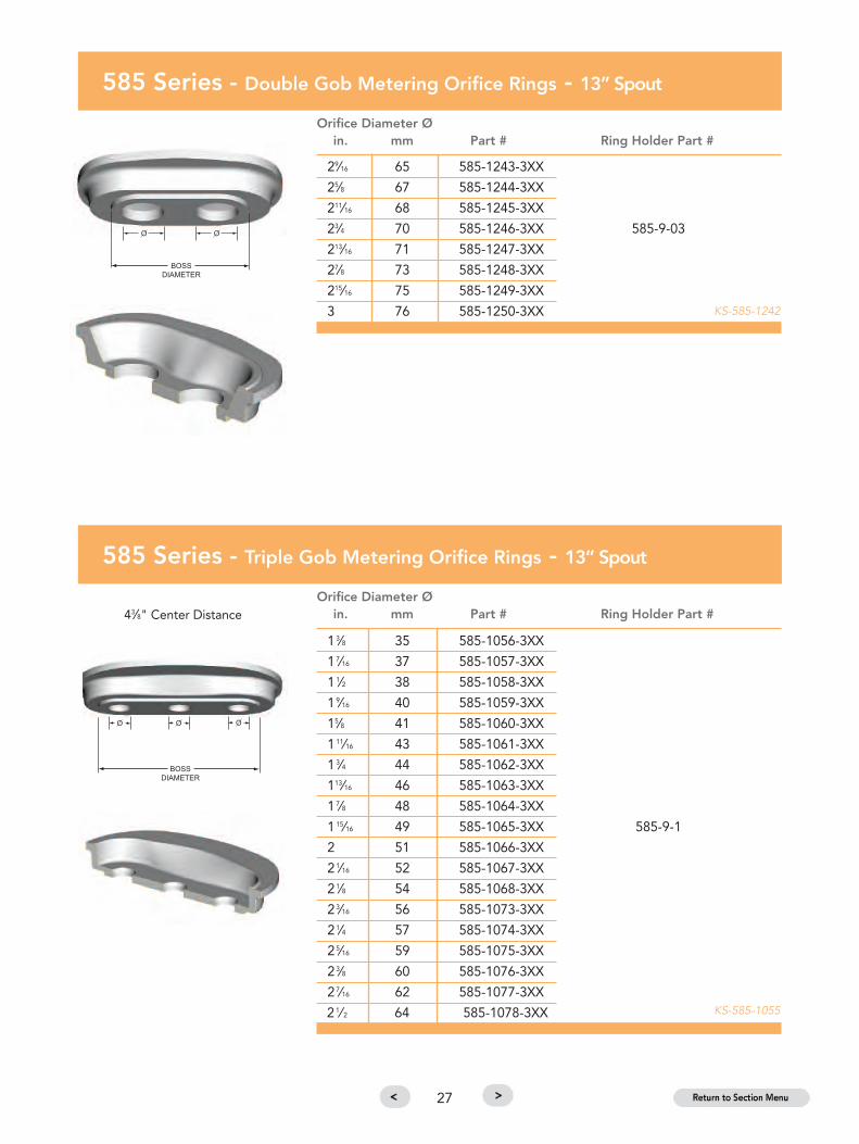
585 Series - Double Gob Metering Orifice Rings - 13” Spout
Orifice Diameter Ø in. mm Part # Ring Holder Part #
29⁄16 65 585-1243-3XX
25⁄8 67 585-1244-3XX
211⁄16 68 585-1245-3XX
23⁄4 70 585-1246-3XX 585-9-03
213⁄16 71 585-1247-3XX
27⁄8 73 585-1248-3XX
215⁄16 75 585-1249-3XX
3 76 585-1250-3XX KS-585-1242
585 Series - Triple Gob Metering Orifice Rings - 13” Spout
Orifice Diameter Ø in. mm Part # Ring Holder Part #
13⁄8 35 585-1056-3XX
17⁄16 37 585-1057-3XX
11⁄2 38 585-1058-3XX
19⁄16 40 585-1059-3XX
15⁄8 41 585-1060-3XX
111⁄16 43 585-1061-3XX
13⁄4 44 585-1062-3XX
113⁄16 46 585-1063-3XX
17⁄8 48 585-1064-3XX
115⁄16 49 585-1065-3XX 585-9-1
2 51 585-1066-3XX
21⁄16 52 585-1067-3XX
21⁄8 54 585-1068-3XX
23⁄16 56 585-1073-3XX
21⁄4 57 585-1074-3XX
25⁄16 59 585-1075-3XX
23⁄8 60 585-1076-3XX
27⁄16 62 585-1077-3XX
21⁄ 2 64 585-1078-3XX
43⁄8" Center Distance
KS-585-1055

28
585 Series - Quad Gob Metering Orifice Rings - 13” Spout
Orifice Diameter Ø in. mm Part # Ring Holder Part #
13⁄8 35 585-1129-3XX
17⁄16 37 585-1130-3XX
11⁄2 38 585-1131-3XX
19⁄16 40 585-1132-3XX
15⁄8 41 585-1133-3XX
111⁄16 43 585-1134-3XX
13⁄4 44 585-1135-3XX 585-9-1
113⁄16 46 585-1136-3XX
17⁄8 48 585-1137-3XX
115⁄16 49 585-1138-3XX
2 51 585-1139-3XX
21⁄16 52 585-1140-3XX
21⁄8 54 585-1141-3XX
23⁄16 56 585-1142-3XX
21⁄4 57 585-1143-3XX
3" Center Distance
KS-585-1126

29
Hard & Soft Gaskets for Orifice Rings - RCF Material
Type of Gasket Description Part #
Soft Gasket 5" Gasket for Standard Orifice Ring 59-94670
Hard Gasket 5" Gasket for Standard Orifice Ring 59-94671
Soft Gasket 7" Gasket for Standard Orifice Ring 59-94672
Hard Gasket 7" Gasket for Standard Orifice Ring 59-94673
Soft Gasket 8" Gasket for Standard Orifice Ring 59-94697
Hard Gasket 8" Gasket for Standard Orifice Ring 59-94698
Soft Gasket 9" Gasket for Standard Orifice Ring 59-94682
Hard Gasket 9" Gasket for Standard Orifice Ring 59-94683
Soft Gasket 10" Gasket for Standard Orifice Ring 59-94674
Hard Gasket 10" Gasket for Standard Orifice Ring 59-94675
Soft Gasket 12" Gasket for Standard Orifice Ring 59-94706
Hard Gasket 12" Gasket for Standard Orifice Ring 59-94707
Soft Gasket 13" Gasket for Standard Orifice Ring 59-94680
Hard Gasket 13" Gasket for Standard Orifice Ring 59-94681
Soft Gasket 8" Gasket for Metering Orifice Ring 59-94708
Hard Gasket 8" Gasket for Metering Orifice Ring 59-94709
Soft Gasket 9" Gasket for Metering Orifice Ring 59-94710
Hard Gasket 9" Gasket for Metering Orifice Ring 59-94711
Soft Gasket 10”/11" Gasket for Metering Orifice Ring 59-94676
Hard Gasket 10”/11" Gasket for Metering Orifice Ring 59-94677
Soft Gasket 13" Gasket for Metering Orifice Ring 59-94678
Hard Gasket 13" Gasket for Metering Orifice Ring 59-94679
KS-59-94669
Standard Orifice Ring Gasket Assembly Metering Orifice Ring Gasket Assembly

30
Hard & Soft Gaskets for Orifice Rings - Bio-Soluble Material
Type of Gasket Description Part #
Soft Gasket 5" Gasket for Standard Orifice Ring 59-34920
Hard Gasket 5" Gasket for Standard Orifice Ring 59-34921
Soft Gasket 7" Gasket for Standard Orifice Ring 59-34922
Hard Gasket 7" Gasket for Standard Orifice Ring 59-34923
Soft Gasket 8" Gasket for Standard Orifice Ring 59-34924
Hard Gasket 8" Gasket for Standard Orifice Ring 59-34925
Soft Gasket 9" Gasket for Standard Orifice Ring 59-34926
Hard Gasket 9" Gasket for Standard Orifice Ring 59-34927
Soft Gasket 10" Gasket for Standard Orifice Ring 59-34928
Hard Gasket 10" Gasket for Standard Orifice Ring 59-34929
Soft Gasket 12" Gasket for Standard Orifice Ring 59-34930
Hard Gasket 12" Gasket for Standard Orifice Ring 59-34931
Soft Gasket 13" Gasket for Standard Orifice Ring 59-34932
Hard Gasket 13" Gasket for Standard Orifice Ring 59-34933
Soft Gasket 8" Gasket for Metering Orifice Ring 59-34934
Hard Gasket 8" Gasket for Metering Orifice Ring 59-34935
Soft Gasket 9" Gasket for Metering Orifice Ring 59-34936
Hard Gasket 9" Gasket for Metering Orifice Ring 59-34937
Soft Gasket 10"/11" Gasket for Metering Orifice Ring 59-34938
Hard Gasket 10"/11" Gasket for Metering Orifice Ring 59-34939
Soft Gasket 13" Gasket for Metering Orifice Ring 59-34940
Hard Gasket 13" Gasket for Metering Orifice Ring 59-34941
KS 59-34669
Standard Orifice Ring Gasket Assembly Metering Orifice Ring Gasket Assembly

Plungers
Tubes
Spouts
Orifice R
ings
& Gaskets
Spout
Assem
blies
Stirrers &Rotor Seg
ments
Insulation,Cem
ents &Hard
Bricks
ForehearthMaintenance Item
s
GlasshouseCrucib
les& Accessories
TechnicalReferences
MSD
SMaterial SafetyData Sheet
USA, OWENSVILLE, MOPlant number for technical assistance Telephone +1 (573) 437 2132Ordering +1 800 243 0048
31
Plungers
Improved Gob Shaping
The formulation and manufacture of expendable
refractories has become increasingly important as
demands on the feeder have increased.
Emhart Glass’ 345 (mullite), 333 (zircon-mullite), and 315
(zircon-mullite), have been demonstrating excellent
wear characteristics when used for refractory plungers.
These materials are ideal solutions for today’s more
aggressive production environments with higher pull
rates.
Click the Section Tabs at right to navigate by section
or click the Menu below to navigate to pages in this section.

For special applications, alternative refractory materialsare available. Please contact your nearest Emhart Glassrepresentative.
PlungersMaterial Data
315 333 345
ZrO2 20 11 --Al2O3 11 73 83SiO2 69 15 16Density (g/cc) 3.1 3.0 2.6Porosity (%) 19 18 19MOR (MPa) 21.4 17.9 14.5
All data is subject to reasonable deviations and not to be usedfor specification purposes.
32
Refractory Part Numbers
123-4567- 3XXEmhart GlassPart Number
Emhart GlassMaterial

3 76 251⁄2 648 23⁄4 70 144-11794-3XX
31⁄4 83 26 660 31⁄8 79 144-780-3XX
31⁄2 89 26 660 31⁄8 79 144-781-3XX
33⁄4 95 26 660 31⁄8 79 144-3985-3XX
31⁄2 89 27 686 31⁄8 79 81-4590-3XX
41⁄4 108 27 686 31⁄8 79 81-4593-3XX
5 127 27 686 31⁄8 79 81-4596-3XX
21⁄2 63 27 686 23⁄8 60 144-1246-3XX
23⁄4 70 27 686 23⁄8 60 144-1217-3XX
3 76 27 686 23⁄4 70 144-1218-3XX
31⁄4 83 27 686 23⁄4 70 81-4566-3XX
31⁄4 83 27 686 31⁄8 79 81-4589-3XX
31⁄2 89 27 686 31⁄8 79 81-4590-3XX
33⁄4 95 27 686 31⁄8 79 81-4591-3XX
4 102 27 686 31⁄8 79 81-4592-3XX
41⁄4 108 27 686 31⁄8 79 81-4593-3XX
41⁄2 114 27 686 31⁄8 79 81-4594-3XX
43⁄4 121 27 686 31⁄8 79 81-4595-3XX
5 127 27 686 31⁄8 79 81-4596-3XX
13⁄4 45 30 762 2 51 501-5681-3XX
2 51 30 762 2 51 501-5680-3XX
21⁄8 54 30 762 2 51 501-6159-3XX
21⁄4 57 30 762 2 51 501-5679-3XX
23⁄8 60 30 762 2 51 501-5678-3XX
21⁄2 64 30 762 2 51 501-5582-3XX
3 76 30 762 23⁄4 70 503-5652-3XX
31⁄4 83 30 762 23⁄4 70 503-5653-3XX
31⁄2 89 30 762 23⁄4 70 503-5654-3XX
4 102 30 762 23⁄4 70 503-5697-3XX
31⁄4 83 30 762 31⁄8 79 503-6707-3XX
31⁄2 89 30 762 31⁄8 79 503-6708-3XX
33⁄4 95 30 762 31⁄8 79 503-6709-3XX
4 102 30 762 31⁄8 79 503-6800-3XX
41⁄2 114 30 762 31⁄8 79 503-6802-3XX
51⁄2 140 30 762 31⁄8 79 503-6809-3XX
3 76 301⁄2 775 23⁄4 70 144-13842-3XX
Plungers - Ball Point X Y Z
in. mm in. mm in. mm Part#
33

3 76 301⁄2 775 31⁄8 79 144-12237-3XX
31⁄4 83 301⁄2 775 31⁄8 79 144-12238-3XX
31⁄2 89 301⁄2 775 31⁄8 79 144-12239-3XX
33⁄4 95 301⁄2 775 31⁄8 79 144-13116-3XX
4 102 301⁄2 775 31⁄8 79 144-13117-3XX
41⁄4 108 301⁄2 775 31⁄8 79 144-13118-3XX
41⁄2 114 301⁄2 775 31⁄8 79 144-13119-3XX
31⁄2 89 311⁄8 791 31⁄8 79 29-607-3XX
33⁄4 95 311⁄8 791 31⁄8 79 144-5470-3XX
4 102 311⁄8 791 31⁄8 79 144-5471-3XX
13⁄4 44 313⁄4 806 2 51 515-5172-3XX
2 51 313⁄4 806 2 51 515-5173-3XX
21⁄4 57 313⁄4 806 2 51 515-5174-3XX
23⁄8 60 313⁄4 806 2 51 515-5175-3XX
21⁄2 64 313⁄4 806 2 51 515-5176-3XX
2 51 32 812 2 51 501-6318-3XX
21⁄8 54 32 812 2 51 501-6292-3XX
21⁄4 57 32 812 2 51 501-6313-3XX
23⁄8 60 32 812 2 51 501-6304-3XX
21⁄2 64 32 812 2 51 501-6314-3XX
3 76 32 812 23⁄4 70 503-6562-3XX
31⁄4 83 32 812 23⁄4 70 503-6563-3XX
31⁄2 89 32 812 23⁄4 70 503-6564-3XX
4 102 32 812 23⁄4 70 503-6565-3XX
31⁄4 83 321⁄8 816 31⁄8 79 58-2573-3XX
31⁄2 89 321⁄8 816 31⁄8 79 58-2574-3XX
33⁄4 95 321⁄8 816 31⁄8 79 58-2575-3XX
4 102 321⁄8 816 31⁄8 79 58-2576-3XX
41⁄4 108 321⁄8 816 31⁄8 79 58-2577-3XX
41⁄2 114 321⁄8 816 31⁄8 79 58-2578-3XX
43⁄4 121 321⁄8 816 31⁄8 79 58-2579-3XX
5 127 321⁄8 816 31⁄8 79 58-2580-3XX
51⁄2 140 321⁄8 816 5 127 113-584-3XX
6 152 321⁄8 816 5 127 113-585-3XX
61⁄2 165 321⁄8 816 5 127 113-586-3XX
Plungers - Ball Point X Y Z
in. mm in. mm in. mm Part#
34

21⁄2 63 27 686 23⁄8 60 144-389-3XX
23⁄4 70 27 686 23⁄8 60 144-388-3XX
3 76 27 686 23⁄4 70 144-490-3XX
31⁄4 83 27 686 31⁄8 79 81-4604-3XX
23⁄4 70 28 711 23⁄4 70 81-4633-3XX
3 76 28 711 23⁄4 70 81-4637-3XX
31⁄2 89 28 711 23⁄4 70 81-4636-3XX
13⁄4 44 30 762 2 51 503-5129-3XX
17⁄8 48 30 762 2 51 503-5128-3XX
2 51 30 762 2 51 503-5094-3XX
21⁄8 54 30 762 2 51 503-5360-3XX
21⁄4 57 30 762 2 51 503-5398-3XX
23⁄8 60 30 762 2 51 503-5361-3XX
21⁄2 63 30 762 2 51 503-6571-3XX
13⁄4 44 32 812 2 51 503-6552-3XX
17⁄8 48 32 812 2 51 503-6553-3XX
2 51 32 812 2 51 503-6551-3XX
21⁄8 54 32 812 2 51 503-6555-3XX
21⁄4 57 32 812 2 51 503-6556-3XX
23⁄8 60 32 812 2 51 503-6557-3XX
21⁄2 63 30 762 2 51 503-6571-3XX
31⁄4 83 321⁄8 816 31⁄8 79 58-2582-3XX
31⁄2 89 321⁄8 816 31⁄8 79 58-2583-3XX
33⁄4 95 321⁄8 816 31⁄8 79 58-2584-3XX
4 102 321⁄8 816 31⁄8 79 58-2585-3XX
41⁄4 108 321⁄8 816 31⁄8 79 58-2586-3XX
Plungers - Standard Point X Y Z
in. mm in. mm in. mm Part#
35

11⁄4 32 27 686 21⁄4 57 81-3929-3XX
11⁄2 38 27 686 21⁄4 57 81-3928-3XX
13⁄4 44 27 686 21⁄4 57 81-3920-3XX
2 51 27 686 21⁄4 57 81-3683-3XX
21⁄2 63 30 762 23⁄4 70 503-5598-3XX
23⁄4 70 30 762 23⁄4 70 503-5599-3XX
3 76 30 762 23⁄4 70 503-5600-3XX
31⁄4 83 30 762 23⁄4 70 503-5601-3XX
23⁄4 70 301⁄2 775 31⁄8 79 144-11792-3XX
23⁄8 60 32 812 23⁄4 70 503-6554-3XX
21⁄2 63 32 812 23⁄4 70 503-6558-3XX
23⁄4 70 32 812 23⁄4 70 503-6559-3XX
3 76 32 812 23⁄4 70 503-6560-3XX
21⁄2 63 321⁄8 816 31⁄8 79 29-611-3XX
23⁄4 70 321⁄8 816 31⁄8 79 29-612-3XX
3 76 321⁄8 816 31⁄8 79 29-610-3XX
Plungers - Tapered Standard Point X Y Z
in. mm in. mm in. mm Part#
36

Pin Type Holder
13⁄4 44 231⁄4 590 11⁄2 38 13⁄4 44 144-15107-3XX
13⁄4 44 28 711 11⁄2 38 13⁄4 44 555-2141-3XX
Slot Type Holder
2 51 28 711 21⁄4 57 11⁄2 38 81-3896-3XX
23⁄8 60 28 711 21⁄4 57 17⁄8 48 81-3743-3XX
21⁄2 63 28 711 21⁄4 57 13⁄4 44 81-3744-3XX
Pin Type Holder
13⁄4 44 28 711 2 51 11⁄4 32 81-4066-3XX
17⁄8 48 28 711 2 51 13⁄8 35 81-4067-3XX
2 51 28 711 2 51 11⁄2 38 81-4068-3XX
21⁄8 54 28 711 2 51 15⁄8 41 81-4069-3XX
23⁄8 60 28 711 2 51 17⁄8 48 81-4070-3XX
21⁄2 63 28 711 2 51 13⁄4 44 81-4071-3XX
Pin Type Holder
13⁄4 44 30 762 2 51 11⁄4 32 81-4131-3XX
17⁄8 48 30 762 2 51 13⁄8 35 81-4132-3XX
2 51 30 762 2 51 11⁄2 38 81-4133-3XX
21⁄8 54 30 762 2 51 15⁄8 41 503-5450-3XX
23⁄8 60 30 762 2 51 17⁄8 48 503-5449-3XX
21⁄2 63 30 762 2 51 13⁄4 44 81-4134-3XX
Pin Type Holder
21⁄2 63 30 762 23⁄4 70 21⁄2 63 515-6017-3XX
Plungers - Offset Point X Y Z W
in. mm in. mm in. mm in. mm Part#
37

33⁄4 95 301⁄2 775 31⁄8 79 144-12240-3XX
Plungers - Fluted Point X Y Z
in. mm in. mm in. mm Part#
31⁄2 89 321⁄8 816 31⁄8 79 501-5338-3XX
Plungers - Square Point X Y Z
in. mm in. mm in. mm Part#
38

13⁄4 44 231⁄4 590 11⁄2 38 144-15106-3XX
13⁄4 44 28 711 11⁄2 38 555-2140-3XX
21⁄2 63 27 686 23⁄8 60 144-2778-3XX
Plungers - Tapered Point X Y Z
in. mm in. mm in. mm Part#
21⁄2 63 321⁄8 816 31⁄8 79 501-5089-3XX
23⁄4 70 321⁄8 816 31⁄8 79 144-14156-3XX
3 76 321⁄8 816 31⁄8 79 29-609-3XX
Plungers - Tapered Ball Point X Y Z
in. mm in. mm in. mm Part#
39

40

Plungers
Tubes
Spouts
Orifice R
ings
& Gaskets
Spout
Assem
blies
Stirrers &Rotor Seg
ments
Insulation,Cem
ents &Hard
Bricks
ForehearthMaintenance Item
s
GlasshouseCrucib
les& Accessories
TechnicalReferences
MSD
SMaterial SafetyData Sheet
USA, OWENSVILLE, MOPlant number for technical assistance Telephone +1 (573) 437 2132Ordering +1 800 243 0048
Tubes
Better Thermal Shock & Wear Resistance
Feeder tubes must display a combination of resistance
to corrosion and thermal shock to survive the harsh
conditions in service. Emhart Glass’ 345 (mullite), 333
(zircon-mullite), and 315 (zircon-mullite) demonstrate
excellent wear resistance and resistance to thermal
shock. When used in the Metering Spout tube
application, typical service lives of six to seven months
have been reported.
Many Emhart Glass tubes, especially the self-centering
555 and 585 types, are precision ground to assure that
as the tube rotates the total runout at the glass end is
minimized.
Click the Section Tabs at right to navigate by section
or click the Menu below to navigate to pages in this section.
41

For special applications, alternative refractory materialsare available. Please contact your nearest Emhart Glassrepresentative.
TubesMaterial Data
315 333 345
ZrO2 20 11 --Al2O3 11 73 83SiO2 69 15 16Density (g/cc) 3.1 3.0 2.6Porosity (%) 19 18 19MOR (MPa) 21.4 17.9 14.5
All data is subject to reasonable deviations and not to be usedfor specification purposes.
42
Refractory Part Numbers
123-4567- 3XXEmhart GlassPart Number
Emhart GlassMaterial

5” (127 mm) 17 432 144-783-3XX 144-15830-3XX
18 457 144-3971-3XX
6” (152 mm) 17 432 144-12949-3XX
18 457 144-13124-3XX 144-15998-3XX
211⁄2 546 144-11649-3XX 144-15754-3XX
7” (178 mm) 211⁄2 546 58-2510-3XX 58-3192-3XX
23 584 81-4200-3XX
27 686 81-3479-3XX
28 711 115-549-3XX
30 762 63-729-3XX
8” (203 mm) 24 610 194-5643-3XX
27 686 503-6115-3XX
9” (229 mm) 263⁄8 670 501-5000-3XX
10” (254 mm) 303⁄4 781 503-6566-3XX
325⁄8 829 501-5599-3XX
11” (279 mm) 261⁄8 664 501-6126-3XX
28 711 515-5006-3XX
Tubes - Plain Type
Precision TubeGround to
Inside L .032 RunoutDiameter Ø in. mm Part # Part #
43

44
17 432 71⁄4 184 7⁄8 22 4 144-14379-3XX
17 432 71⁄4 184 1 25 4 144-15870-3XX
211⁄2 546 11 279 7⁄8 22 4 144-14380-3XX 144-15905-3XX
18 457 71⁄4 184 7⁄8 22 4 144-14376-3XX
211⁄2 546 11 279 7⁄8 22 4 144-14220-3XX 144-15755-3XX
211⁄2 546 111⁄2 292 7⁄8 22 4 194-5162-3XX
23 584 93⁄4 248 7⁄8 22 4 81-4201-3XX
23 584 111⁄2 292 7⁄8 22 4 144-15175-3XX
24 610 111⁄2 292 7⁄8 22 4 194-5301-3XX 194-5744-3XX
2411⁄16 627 111⁄2 292 7⁄8 22 4 81-4295-3XX
27 686 12 305 7⁄8 22 4 81-3904-3XX
27 686 121⁄2 318 7⁄8 22 4 503-5845-3XX
23 584 101⁄2 267 7⁄8 22 4 501-7087-3XX
24 610 111⁄2 292 11⁄2 38 3 501-5986-3XX
24 610 12 305 2 51 3 501-5999-3XX
24 610 13 330 7⁄8 22 4 194-5637-3XX
251⁄4 641 13 330 7⁄8 22 4 501-7088-3XX
26 660 121⁄2 318 7⁄8 22 4 115-2029-3XX
27 686 13 330 7⁄8 22 4 501-5158-3XX
283⁄4 730 13 330 7⁄8 22 4 503-5891-3XX
261⁄8 664 121⁄2 318 7⁄8 22 4 503-5369-3XX 503-6544-3XX
261⁄8 664 13 330 11⁄4 32 4 501-5240-3XX 503-6547-3XX
261⁄8 664 13 330 11⁄2 38 4 501-5767-3XX 503-6549-3XX
261⁄8 664 13 330 13⁄4 44 4 503-5741-3XX
261⁄8 664 * — 2 51 3 501-5391-3XX 503-6546-3XX
27 686 121⁄2 318 2 51 4 501-6160-3XX
27 686 14 356 11⁄2 38 4 501-6485-3XX
27 686 15 381 11⁄2 38 4 501-6426-3XX
271⁄4 692 15 381 2 51 3 501-6231-3XX
28 711 ** — 2 51 3 501-7010-3XX
28 711 16 406 2 51 4 501-7014-3XX
281⁄8 714 141⁄2 368 7⁄8 22 4 515-6151-3XX
281⁄8 714 15 381 7⁄8 22 4 501-5997-3XX
281⁄8 714 15 381 11⁄4 32 4 501-6097-3XX
281⁄8 714 *** — 2 51 3 503-5936-3XX 503-6570-3XX
281⁄8 714 15 381 11⁄2 38 4 501-6372-3XX 501-6410-3XX
283⁄8 721 151⁄4 387 11⁄2 38 3 501-7047-3XX
Tubes - VentedInside Hole Precision
Diameter L X Diam. No. GroundØ in. mm in. mm in. mm Holes Part # Part #
*Precision ground to .032 maximum runout measured 1” from bottom
of tube
44
6”(152 mm)
5”(127 mm)
7”(178 mm)
8”(203 mm)
10”(254 mm)
10”(254 mm)
* Vent holes @ 13 / 131⁄4 / 131⁄2
** Vent holes @ 141⁄2 / 15 / 151⁄2
*** Vent holes @ 15 / 151⁄4 / 151⁄2
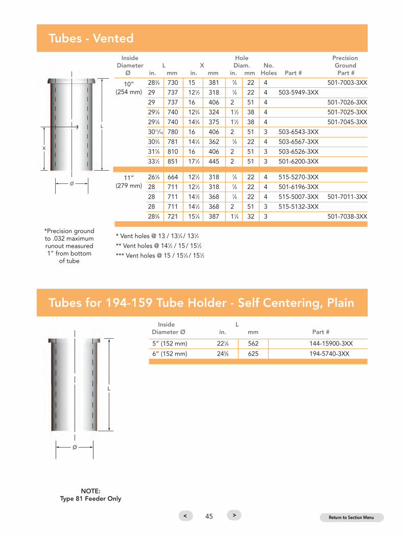
283⁄4 730 15 381 7⁄8 22 4 501-7003-3XX
29 737 121⁄2 318 7⁄8 22 4 503-5949-3XX
29 737 16 406 2 51 4 501-7026-3XX
291⁄8 740 123⁄4 324 11⁄2 38 4 501-7025-3XX
291⁄8 740 143⁄4 375 11⁄2 38 4 501-7045-3XX
3011⁄16 780 16 406 2 51 3 503-6543-3XX
303⁄4 781 141⁄4 362 7⁄8 22 4 503-6567-3XX
317⁄8 810 16 406 2 51 3 503-6526-3XX
331⁄2 851 171⁄2 445 2 51 3 501-6200-3XX
261⁄8 664 121⁄2 318 7⁄8 22 4 515-5270-3XX
28 711 121⁄2 318 7⁄8 22 4 501-6196-3XX
28 711 141⁄2 368 7⁄8 22 4 515-5007-3XX 501-7011-3XX
28 711 141⁄2 368 2 51 3 515-5132-3XX
283⁄8 721 151⁄4 387 11⁄4 32 3 501-7038-3XX
Tubes - VentedInside Hole Precision
Diameter L X Diam. No. GroundØ in. mm in. mm in. mm Holes Part # Part #
* Vent holes @ 13 / 131⁄4 / 131⁄2
** Vent holes @ 141⁄2 / 15 / 151⁄2
*** Vent holes @ 15 / 151⁄4 / 151⁄2
5” (152 mm) 221⁄8 562 144-15900-3XX
6” (152 mm) 245⁄8 625 194-5740-3XX
Tubes for 194-159 Tube Holder - Self Centering, Plain
Inside LDiameter Ø in. mm Part #
*Precision ground to .032 maximum runout measured 1” from bottom
of tube
45
10”(254 mm)
11”(279 mm)
NOTE:Type 81 Feeder Only

7" (178 mm) 233⁄8 594 *555-1520-3XX
263⁄8 670 *555-1057-3XX
8” (203 mm) 233⁄8 594 *555-1521-3XX
263⁄8 670 *555-1058-3XX
10" (254 mm) 263⁄8 670 555-1001-3XX
Tubes for 555-1 Tube Holder - Self Centering, Plain
Inside LDiameter Ø in. mm Part #
*139⁄16 (345 mm) Flange ODImportant: Tube selection is based on flange OD as well as tube ID and length.
6" (152 mm) 245⁄8 625 111⁄2 292 7⁄8 22 4 194-5747-3XX
7" (177 mm) 245⁄8 625 111⁄2 292 7⁄8 22 4 194-5748-3XX
8" (203 mm) 22 559 13 330 7⁄8 22 4 501-7050-3XX
23 584 13 330 7⁄8 22 4 501-7058-3XX
2411⁄16 627 111⁄2 292 7⁄8 22 4 194-5764-3XX
2411⁄16 627 13 330 7⁄8 22 4 501-7030-3XX
Tubes for 194-159 Tube Holder - Self Centering, VentedHole
Inside L X Diam. No.Diameter Ø in. mm in. mm in. mm Holes Part #
NOTE:Type 81 Feeder Only
46

5” (127 mm) 22 559 9 229 7⁄8 22 4 *555-2071-3XX
6” (152 mm) 22 559 9 229 7⁄8 22 4 *555-2072-3XX
7” (178 mm) 22 559 9 229 7⁄8 22 4 *555-2073-3XX
233⁄8 594 91⁄2 241 7⁄8 22 3 **555-1518-3XX
24 610 11 279 7⁄8 22 4 *555-2094-3XX
25 635 11 279 7⁄8 22 4 *501-7082-3XX
263⁄8 670 121⁄2 318 7⁄8 22 3 **555-1056-3XX
263⁄8 670 121⁄2 318 7⁄8 22 4 *555-2154-3XX
8” (203 mm) 233⁄8 594 91⁄2 241 7⁄8 22 3 **555-1519-3XX
24 610 11 279 7⁄8 22 4 *555-2095-3XX
24 610 12 305 11⁄2 38 3 **555-2543-3XX
263⁄8 670 121⁄2 318 7⁄8 22 4 *555-2155-3XX
263⁄8 670 121⁄2 318 7⁄8 22 3 **555-1340-3XX
263⁄8 670 121⁄2 318 11⁄2 38 3 **555-1837-3XX
10" (254 mm) 233⁄8 594 10 254 7⁄8 22 3 555-1415-3XX
263⁄8 670 121⁄2 318 7⁄8 22 3 555-1052-3XX
263⁄8 670 121⁄2 318 7⁄8 22 4 555-1765-3XX
263⁄8 670 121⁄2 318 2 51 3 555-1795-3XX
263⁄8 670 121⁄2 318 2 51 4 555-1826-3XX
263⁄8 670 13 330 2 51 3 555-1779-3XX
263⁄8 670 13*** 330 11⁄2 38 4 555-1794-3XX
263⁄8 670 13 330 2 51 3 555-1788-3XX
283⁄8 721 151⁄4 387 2 51 3 555-1653-3XX
283⁄8 721 151⁄4 387 11⁄2 38 3 555-1822-3XX
283⁄8 721 151⁄4 387 7⁄8 22 3 555-1181-3XX
11" (279 mm) 283⁄8 721 151⁄4 387 7⁄8 22 3 555-1808-3XX
283⁄8 721 151⁄4 387 11⁄4 32 3 501-7035-3XX
283⁄8 721 151⁄4 387 11⁄2 38 3 501-7053-3XX
283⁄8 721 151⁄4 387 2 51 3 555-2663-3XX
12" (305 mm) 283⁄8 721 151⁄4 387 7⁄8 22 3 555-1807-3XX
Tubes for 555-1 Tube Holder - Self Centering, VentedHole
Inside L X Diam No.Diameter Ø in. mm in. mm in. mm Holes Part #
* 11” (279 mm) Flange OD** 139⁄16” (345 mm) Flange OD*** Staggered 13 - 131⁄4 - 131⁄2
Important: Tube selection is based on flange OD as well as tube ID and length.
47

48
Insulation Retainers
Style A (in.) B (in.) C (in.) Part #
10” Tube SG 2 - - 555-2531-3XX
10” Tube DG (3) 2 11⁄2 3 555-2652-3XX
10” Tube DG (43⁄8) 2 23⁄16 43⁄8 555-2532-3XX
10” Tube TG (3) 15⁄8 3 6 555-2533-3XX
11” Tube SG 2 - - 555-2681-3XX
11”-12” Tube DG (43⁄8) 2 23⁄16 43⁄8 555-1814-3XX
11” Tube TG (3) 15⁄8 3 6 555-1815-3XX
12” Tube TG (43⁄8) 2 311⁄16 73⁄8 555-1841-3XX
Note: Insulation retainers are shipped in marked, matchedsets and should be installed as such.
KS-555-2530KS-555-1813

49
Metering Tubes
Diameter Ø 81 Spout 503 Spout 515 Spout 585 Spout
8” 81-4698-3XX
9” 81-4784-3XX
10” 555-2133-3XX 555-2132-3XX
11” 555-2130-3XX 555-2126-3XX
13” 585-1054-3XX
Note: All metering tubes have 3 vent holes for use with heat baffles.
The vent hole diameters are: - 81 metering, 1" - 503 metering, 11/2"- 515 metering, 11/2" - 585 metering, 11/2"
Metering Spout Heat Baffle
Description 81 Spout 503 Spout 515 Spout 585 Spout
8” SG 81-4830-3XX
8” DG 81-4697-3XX
9” TG 555-2134-3XX
10” SG 555-2139-3XX 555-2139-3XX
10” DG 555-2129-3XX 555-2129-3XX
10” TG N/A N/A
11” SG 555-2136-3XX 555-2136-3XX
11” DG 555-2131-3XX 555-2131-3XX
11” TG 555-2127-3XX 555-2127-3XX
13” DG 585-1098-3XX
13” TG 585-1071-3XX13” QG
Note: Heat baffles are shipped in marked, matched sets of two and should beinstalled as such.

50

Plungers
Tubes
Spouts
Orifice R
ings
& Gaskets
Spout
Assem
blies
Stirrers &Rotor Seg
ments
Insulation,Cem
ents &Hard
Bricks
ForehearthMaintenance Item
s
GlasshouseCrucib
les& Accessories
TechnicalReferences
MSD
SMaterial SafetyData Sheet
USA, OWENSVILLE, MOPlant number for technical assistance Telephone +1 (573) 437 2132Ordering +1 800 243 0048
Spouts
Shape Stability & Corrosion Resistance
Advanced manufacturing process developments have
been implemented for spout bowls, to meet the
stringent demands of the glass container forming
process.
Emhart Glass’ 333, 315, and 301 are bonded AZS
(zircon-mullite) materials containing various degrees of
ZrO2. They are produced at higher firing temperatures,
resulting in improved density and a highly corrosion-
resistant matrix. These performance characteristics
make our AZS range an excellent choice for Emhart
Glass spout bowls.
Click the Section Tabs at right to navigate by section
or click the Menu below to navigate to pages in this section.
51

52
For special applications, alternative refractory materialsare available. Please contact your nearest Emhart Glassrepresentative.
SpoutsMaterial Data
301* 315 333
ZrO2 35 20 11Al2O3 45 11 73SiO2 19 69 15Density (g/cc) 3.2 3.1 3.0Porosity (%) 18 19 18MOR (MPa) 20.0 21.4 17.9
*New formula containing 35% ZrO2. Mix was launched in2011.
All data is subject to reasonable deviations and not to be usedfor specification purposes.
52
Refractory Part Numbers
123-4567- 3XXEmhart GlassPart Number
Emhart GlassMaterial

Straight Throat with Flat Tube Seat SpoutsØ X Throat
Throat Spout C/LDiameter Depth Description with orin. mm in. mm Part # Entrance Width Offset
5 127 53⁄4 146 144-14179-3XX(\) For 144 Feeder-STD, 14” C\L
73⁄4 197 6 152 144-15145-3XX For 144 Feeder-STD, 14” C\L
7 178 91⁄2 241 144-15030-3XX(\) For 144 Feeder-Deep, 16” C\L
5 127 91⁄2 241 29-600-3XX(\) For 144 Feeder-Deep, 14” C\L
7 178 71⁄4 184 81-3795-3XX For 81 Feeder-STD, 16” Turbex Offset
7 178 91⁄2 241 81-3792-3XX For 81 Feeder-Deep, 16” Turbex Offset
7 178 10 254 81-4015-3XX For 81 Feeder-Deep, 18” C\L
8 203 10 254 81-6342-3XX For 81 Feeder-Deep, 18” C\L
8 203 71⁄4 184 81-4487-3XX For 81 Feeder-STD, 18” C\L
7 178 10 254 194-5223-3XX For 194 Feeder-Deep, 18” C\L
7 178 71⁄4 184 194-5224-3XX For 194 Feeder-Shallow, 18” C\L
8 203 71⁄4 184 81-6341-3XX For 194 Feeder-STD, 18” C\L
7 178 115⁄16 287 115-870-3XX For 115 Feeder-Deep, 22” C\L
7 178 115⁄16 287 503-5400-3XX For 503 Feeder-Deep, 22” C\L
10 254 71⁄4 184 503-6231-3XX For 503 Feeder-STD, 22” C\L
10 254 115⁄16 287 503-5080-3XX For 503 Feeder-Deep, 22” C\L
10 254 115⁄16 287 503-3845-3XX For 503 Feeder-Deep, 22” C\L(Reinforced)
10 254 115⁄16 287 503-5938-3XX For 503 Feeder-Deep, 22” C\L
12 305 13 330 515-6105-3XX For 515 Feeder- Extra Deep 24” C\L
10 254 13 330 515-5133-3XX For 503 Feeder-Extra Deep C\LWith Curb, 24”
12 305 13 330 515-5139-3XX For 515 Feeder- Deep C\LWith Curb at Entrance, 24”
(\) This symbol designates sloped channel entrance.
Glass Depth 1” Below “X” Dimension
Small Spout
Standard Spout
Curbed Spout
53
Small Spouts
Standard Spouts
Curbed Spouts

Tapered Throat with Flat Tube Seat SpoutsØ X Throat
Throat Spout C/LDiameter Depth Description with or
in. mm in. mm Part # Entrance Width Offset
6/5 152/127 91⁄2 241 144-14177-3XX (\) For 144 Feeder C/LDeep, 14”
8/7 203/178 91⁄2 241 81-4381-3XX For 81 Feeder TurbexDeep, 16” Offset
8/7 203/178 10 254 81-4575-3XX** For 81 Feeder C\LDeep, 18”
8/7 203/178 10 254 194-5636-3XX For 194 Feeder C\LDeep, 18”
8/7 203/178 115⁄16 287 503-5963-3XX For 503 Feeder C\LInclined, 22”
8/7 203/178 115⁄16 287 503-6616-3XX For 503 Feeder C\LStraight, 22”
11/10 279/254 115⁄16 287 501-6210-3XX For 503 Feeder C\LDeep, 22”
11/10 279/254 13 330 515-5314-3XX For 515 Feeder C\LW/curb, 24”
11/10 279/254 13 330 515-5001-3XX For 515 Feeder C\LW/O curb, 24”
(\) This symbol designates sloped channel entrance.Glass Depth 1” Below “X” Dimension** Replaces 81-4342
54

Tapered Throat with Raised Tube Seat SpoutsØ X Throat
Throat Spout C/LDiameter Depth Description with orin. mm in. mm Part # Entrance Width Offset
6/5 152/127 91⁄2 254 144-14180-3XX (\) For 144 Feeder- C/L Deep, 14”
6/5 152/127 10 254 81-4646-3XX For 81 Feeder- C/L Deep, 18”
(\) This symbol designates sloped channel entrance.
Glass Depth 1” Below “X” Dimension
Straight Throat with Raised Tube Seat SpoutsØ X Throat
Throat Spout C/LDiameter Depth Description with orin. mm in. mm Part # Entrance Width Offset
5 127 53⁄4 152 144-704-3XX (\) For 144 Feeder C\L
STD, 14”
5 127 53⁄4 152 144-14178-3XX (\) For 144 Feeder C\L
A\S-STD,14”
5 127 91⁄4 235 29-890-3XX (\) For 144 Feeder C\L
Deep, 14”
7 178 91⁄2 241 58-1939-3XX (\) For 144/58 Feeder C\L
Deep, 20”
7 178 91⁄2 241 81-3908-3XX For 81 Feeder Turbex Deep, 16” Offset
(\) This symbol designates sloped channel entrance.Glass Depth 1” Below “X” Dimension
55

6/5 152/127 71⁄4 184 81-4523-3XX For 81 Feeder-STD, 14”*
6/5 152/127 10 254 81-4635-3XX For 81 Feeder-Deep, 18”
8/7 203/178 71⁄4 184 81-4539-3XX For 81 Feeder-STD, 18”
8/7 203/178 10 254 81-4575-3XX For 81 Feeder-Deep, 18”
* To be used in 81 type spout casing.
56
X-Section
5 127 71⁄4 184 81-4522-3XX For 81 Feeder-STD, 14”*
5 127 10 254 81-4577-3XX For 81 Feeder-Deep, 14”*
5 127 71⁄4 184 81-4535-3XX For 81 Feeder-STD, 18”
5 127 10 254 81-4572-3XX For 81 Feeder-Deep, 18”
7 178 71⁄4 184 81-4537-3XX For 81 Feeder-STD, 18”
7 178 10 254 81-4015-3XX For 81 Feeder-Deep, 18”
8 203 71⁄4 184 81-4538-3XX For 81 Feeder-STD, 18”
8 203 10 254 81-4574-3XX For 81 Feeder-Deep, 18”
* To be used in 81 type spout casing.
81 or 555 Feeder Spouts - Straight Throat with Flat Tube Seat
Ø XThroat Inside
Diameter Depth Description within. mm in. mm Part # Entrance Width
81 or 555 Feeder Spouts - Tapered Throat with Flat Tube Seat
Ø XThroat Inside
Diameter Depth Description within. mm in. mm Part # Entrance Width

81 Metering Spouts - For 8” Tube, 43⁄8” CD Double Gob - 10” Deep
Shear Shear Angle Part # Angle Part #
CL 0º 81-4672-3XX 90º L 81-4679-3XX
5º R 81-4673-3XX 85º L 81-4680-3XX
10º R 81-4674-3XX 80º L 81-4768-3XX
15º R 81-4675-3XX 75º L 81-4682-3XX
20º R 81-4676-3XX 70º L 81-4683-3XX
25º R 81-4677-3XX 65º L 81-4684-3XX
30º R 81-4678-3XX 60º L 81-4685-3XX
55º L 81-4686-3XX
50º L 81-4687-3XX
45º L 81-4688-3XX
40º L 81-4689-3XX
35º L 81-4690-3XX
30º L 81-4691-3XX
25º L 81-4692-3XX
20º L 81-4693-3XX
15º L 81-4694-3XX
10º L 81-4695-3XX
5º L 81-4696-3XX KS-81-4671
Note: Refractory spouts for metering spout applications will carry a different partnumber for every different angle of shearing.
57
A machine can be installed under a feeder at different angles in order to suit factory conditions. The angle of a machine to a feeder isthe angle between the feeder centerline and the machine centerline. The feeder centerline coincides with the centerline of forehearthchannels. The machine’s centerline is at a right angle to the conveyor axis through the midpoint of the machine. When the feedercenterline and machine centerline coincide the machine is placed in the 0-degree position.
The throat of a metering spout can be adjusted to match the shear angle. Please use the drawing below to determine the appropriatespout.
Metering Spout Shear Angle

58
81 Metering Spouts - For 9” Tube, 3” CD Triple Gob - 10” Deep
Shear Shear Angle Part # Angle Part #
503 Metering Spouts - For 10” Tube - 115/16” Deep
Shear Shear Angle Part # Angle Part #
CL 0º 81-4759-3XX 90º L 81-4766-3XX
5º R 81-4760-3XX 85º L 81-4767-3XX
10º R 81-4761-3XX 80º L 81-4768-3XX
15º R 81-4762-3XX 75º L 81-4769-3XX
20º R 81-4763-3XX 70º L 81-4770-3XX
25º R 81-4764-3XX 65º L 81-4771-3XX
30º R 81-4765-3XX 60º L 81-4772-3XX
55º L 81-4773-3XX
50º L 81-4774-3XX
45º L 81-4775-3XX
40º L 81-4776-3XX
35º L 81-4777-3XX
30º L 81-4778-3XX
25º L 81-4779-3XX
20º L 81-4780-3XX
15º L 81-4781-3XX
10º L 81-4782-3XX
5º L 81-4783-3XX
CL 0º 503-7018-3XX 90º L 503-6882-3XX
5º R 503-7019-3XX 85º L 503-7055-3XX
10º R 503-7020-3XX 80º L 503-7056-3XX
15º R 503-7021-3XX 75º L 503-7057-3XX
20º R 503-7022-3XX 70º L 503-7058-3XX
25º R 503-7023-3XX 65º L 503-7059-3XX
30º R 503-7043-3XX 60º L 503-7060-3XX
35º R 503-7044-3XX 55º L 503-7061-3XX
40º R 503-7045-3XX 50º L 503-7062-3XX
45º R 503-7046-3XX 45º L 503-7063-3XX
50º R 503-7047-3XX 40º L 503-7064-3XX
55º R 503-7048-3XX 35º L 503-7065-3XX
60º R 503-7049-3XX 30º L 503-7066-3XX
65º R 503-7050-3XX 25º L 503-7067-3XX
70º R 503-7051-3XX 20º L 503-7068-3XX
75º R 503-7052-3XX 15º L 503-7069-3XX
80º R 503-7053-3XX 10º L 503-7070-3XX
85º R 503-7054-3XX 5º L 503-7071-3XX
KS-81-4758
KS-503-7017
Note: Refractory spouts for metering spout applications will carry a different partnumber for every different angle of shearing.
Note: Refractory spouts formetering spout applications willcarry a different part number forevery different angle of shearing.
Note: Metering spouts for 10"tube are used for single gob anddouble gob only.

503 Metering Spouts - For 11” Tube - 115/16” Deep
Shear Shear Angle Part # Angle Part #
CL 0º 503-6948-3XX 90º L 503-6966-3XX
5º R 503-6949-3XX 85º L 503-6967-3XX
10º R 503-6950-3XX 80º L 503-6968-3XX
15º R 503-6951-3XX 75º L 503-6969-3XX
20º R 503-6952-3XX 70º L 503-6970-3XX
25º R 503-6953-3XX 65º L 503-6971-3XX
30º R 503-6954-3XX 60º L 503-6972-3XX
35º R 503-6955-3XX 55º L 503-6973-3XX
40º R 503-6956-3XX 50º L 503-6974-3XX
45º R 503-6957-3XX 45º L 503-6975-3XX
50º R 503-6958-3XX 40º L 503-6976-3XX
55º R 503-6959-3XX 35º L 503-6977-3XX
60º R 503-6960-3XX 30º L 503-6978-3XX
65º R 503-6961-3XX 25º L 503-6979-3XX
70º R 503-6962-3XX 20º L 503-6980-3XX
75º R 503-6963-3XX 15º L 503-6981-3XX
80º R 503-6964-3XX 10º L 503-6982-3XX
85º R 503-6965-3XX 5º L 503-6983-3XX
515 Metering Spouts - For 10” Tube - 13” Deep
Shear Shear Angle Part # Angle Part #
Note: Refractory spouts formetering spout applications willcarry a different part number forevery different angle of shearing.
Note: Metering spouts for 10"tube are used for single gob anddouble gob only.
CL 0º 515-5324-3XX 90º L 515-5274-3XX
5º R 515-5325-3XX 85º L 515-5360-3XX
10º R 515-5326-3XX 80º L 515-5361-3XX
15º R 515-5327-3XX 75º L 515-5362-3XX
20º R 515-5328-3XX 70º L 515-5363-3XX
25º R 515-5329-3XX 65º L 515-5364-3XX
30º R 515-5330-3XX 60º L 515-5365-3XX
35º R 515-5331-3XX 55º L 515-5366-3XX
40º R 515-5332-3XX 50º L 515-5367-3XX
45º R 515-5333-3XX 45º L 515-5368-3XX
50º R 515-5352-3XX 40º L 515-5369-3XX
55º R 515-5353-3XX 35º L 515-5370-3XX
60º R 515-5354-3XX 30º L 515-5371-3XX
65º R 515-5355-3XX 25º L 515-5372-3XX
70º R 515-5356-3XX 20º L 515-5373-3XX
75º R 515-5357-3XX 15º L 515-5374-3XX
80º R 515-5358-3XX 10º L 515-5375-3XX
85º R 515-5359-3XX 5º L 515-5376-3XX KS-515-5323
KS-503-6947
Note: Refractory spouts for metering spout applications will carry a different partnumber for every different angle of shearing.
Note: Metering spouts for 11"tube are used for single, doubleand triple gob.
59

60
515 Metering Spouts - For 11” Tube - 13” Deep
Shear Shear Angle Part # Angle Part #
Note: Refractory spouts for
metering spout application will
carry a different part number for
every different angle of shearing.
Note: Metering spouts for 11"
tube are used for single, double
and triple gob.
CL 0º 515-5279-3XX 90º L 515-5297-3XX
5º R 515-5280-3XX 85º L 515-5298-3XX
10º R 515-5281-3XX 80º L 515-5299-3XX
15º R 515-5282-3XX 75º L 515-5300-3XX
20º R 515-5283-3XX 70º L 515-5301-3XX
25º R 515-5284-3XX 65º L 515-5302-3XX
30º R 515-5285-3XX 60º L 515-5276-3XX
35º R 515-5286-3XX 55º L 515-5303-3XX
40º R 515-5287-3XX 50º L 515-5304-3XX
45º R 515-5288-3XX 45º L 515-5305-3XX
50º R 515-5289-3XX 40º L 515-5306-3XX
55º R 515-5290-3XX 35º L 515-5307-3XX
60º R 515-5291-3XX 30º L 515-5308-3XX
65º R 515-5292-3XX 25º L 515-5309-3XX
70º R 515-5293-3XX 20º L 515-5310-3XX
75º R 515-5294-3XX 15º L 515-5311-3XX
80º R 515-5295-3XX 10º L 515-5312-3XX
85º R 515-5296-3XX 5º L 515-5313-3XX KS-515-5275
585 Metering Spouts - For 13” Tube - 13” Deep
Shear Shear Angle Part # Angle Part #
Note: Refractory spouts for
metering spout application will
carry a different part number for
every different angle of shearing.
Note: 585 metering spouts are
used for double gob and triple
gob.
CL 0º 585-1173-3XX 90º L 585-1191-3XX
5º R 585-1174-3XX 85º L 585-1192-3XX
10º R 585-1175-3XX 80º L 585-1193-3XX
15º R 585-1176-3XX 75º L 585-1194-3XX
20º R 585-1177-3XX 70º L 585-1195-3XX
25º R 585-1178-3XX 65º L 585-1196-3XX
30º R 585-1179-3XX 60º L 585-1197-3XX
35º R 585-1180-3XX 55º L 585-1198-3XX
40º R 585-1181-3XX 50º L 585-1199-3XX
45º R 585-1182-3XX 45º L 585-1200-3XX
50º R 585-1183-3XX 40º L 585-1201-3XX
55º R 585-1184-3XX 35º L 585-1202-3XX
60º R 585-1185-3XX 30º L 585-1203-3XX
65º R 585-1186-3XX 25º L 585-1204-3XX
70º R 585-1187-3XX 20º L 585-1205-3XX
75º R 585-1188-3XX 15º L 585-1206-3XX
80º R 585-1189-3XX 10º L 585-1207-3XX
85º R 585-1190-3XX 5º L 585-1208-3XX KS-585-1172

Plungers
Tubes
Spouts
Orifice R
ings
& Gaskets
Spout
Assem
blies
Stirrers &Rotor Seg
ments
Insulation,Cem
ents &Hard
Bricks
ForehearthMaintenance Item
s
GlasshouseCrucib
les& Accessories
TechnicalReferences
MSD
SMaterial SafetyData Sheet
USA, OWENSVILLE, MOPlant number for technical assistance Telephone +1 (573) 437 2132Ordering +1 800 243 0048
Spout Assemblies
Shape Stability & Corrosion Resistance
For the spout assemblies’ spout covers and spout
burner blocks, the materials 338 and 345 are used to
provide the needed shape stability and resistance to
thermal shock. Spout covers are designed with cells to
hold ceramic fiber insulating board shapes which
provide needed insulation.
Click the Section Tabs at right to navigate by section
or click the Menu below to navigate to pages in this section.
61

62
For special applications, alternative refractory materialsare available. Please contact your nearest Emhart Glassrepresentative.
Spout AssembliesMaterial Data
338 345
ZrO2 -- --Al2O3 71 83SiO2 26 16Density (g/cc) 2.5 2.6Porosity (%) 18 19MOR (MPa) 20.0 14.5
All data is subject to reasonable deviations and not to be usedfor specification purposes.
62
Refractory Part Numbers
123-4567- 3XXEmhart GlassPart Number
Emhart GlassMaterial
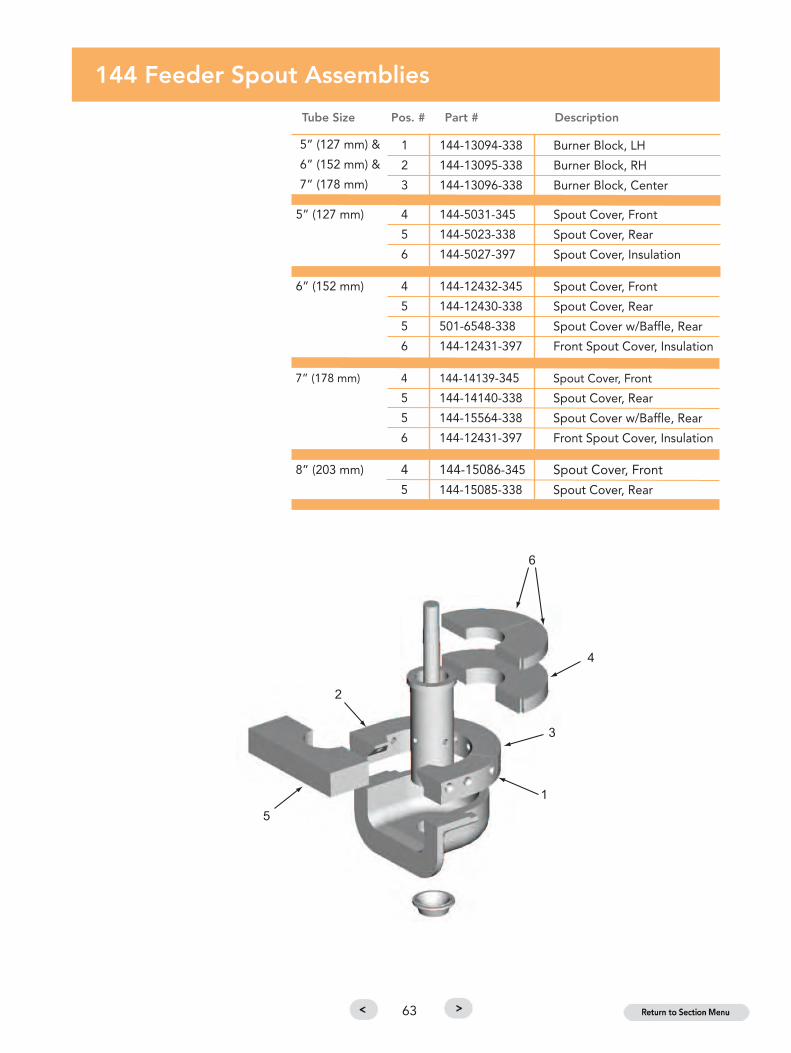
1 144-13094-338 Burner Block, LH
2 144-13095-338 Burner Block, RH
3 144-13096-338 Burner Block, Center
5” (127 mm) 4 144-5031-345 Spout Cover, Front
5 144-5023-338 Spout Cover, Rear
6 144-5027-397 Spout Cover, Insulation
6” (152 mm) 4 144-12432-345 Spout Cover, Front
5 144-12430-338 Spout Cover, Rear
5 501-6548-338 Spout Cover w/Baffle, Rear
6 144-12431-397 Front Spout Cover, Insulation
7” (178 mm) 4 144-14139-345 Spout Cover, Front
5 144-14140-338 Spout Cover, Rear
5 144-15564-338 Spout Cover w/Baffle, Rear
6 144-12431-397 Front Spout Cover, Insulation
8” (203 mm) 4 144-15086-345 Spout Cover, Front
5 144-15085-338 Spout Cover, Rear
144 Feeder Spout Assemblies
Tube Size Pos. # Part # Description
5” (127 mm) &
6” (152 mm) &
7” (178 mm)
63

194 Feeder Spout Assemblies
Tube Size Pos. # Part # Description
1 194-5010-338 Burner Block, LH
2 194-5008-338 Burner Block, RH
3 194-5009-338 Burner Block, Front
7” (178 mm) 4 194-5006-338 Spout Cover, Front
5 194-5005-345 Spout Cover, Rear
5 194-5578-345 Spout Cover w/Baffle, Rear
8” (203 mm) 4 194-5639-338 Spout Cover, Front
5 194-5638-345 Spout Cover w/Baffle, Rear
5 194-5642-345 Spout Cover, Rear
7” (178 mm) &
8” (203 mm)
64

81 Feeder Spout Assemblies
Tube Size Pos. # Part # Description
1 81-2653-338 Burner Block, LH
2 81-2652-338 Burner Block, RH
3 81-2654-338 Burner Block, Front
6” (152 mm) 4 81-3812-338 Spout Cover, Front
5 81-3811-345 Spout Cover, Rear
7” (178 mm) 4 194-5006-338 Spout Cover, Front
5 81-3813-345 Spout Cover, Rear
16” WIDTH OFFSET SPOUTROTATING TUBE
6” (152 mm) &
7” (178 mm)
65

7” (178 mm) &
8” (203 mm) &
10” (254 mm)
81 Feeder Spout Assemblies
Tube Size Pos. # Part # Description
1 81-4033-338 Burner Block, LH
2 81-4034-338 Burner Block, RH
3 81-4032-338 Burner Block, Front
SPOUT COVER WITH 16” OR 22” WIDE EQUALIZING SECTION
7” (178 mm) 4 194-5006-338 Spout Cover, Front
5 81-3813-338 Spout Cover, Rear
8” (203 mm) 4 81-6214-338 Spout Cover, Front
5 81-6217-345 Spout Cover, Rear
10” (254 mm) 4 81-6215-338 Spout Cover, Front
5 81-6219-345 Spout Cover, Rear
SPOUT COVER WITH 26” OR 36” WIDE EQUALIZING SECTION
7” (178 mm) 4 194-5006-338 Spout Cover, Front
5 194-5005-345 Spout Cover, Rear
8” (203 mm) 4 81-6214-338 Spout Cover, Front
5 81-6218-345 Spout Cover, Rear
10” (254 mm) 4 81-6215-338 Spout Cover, Front
5 81-6220-345 Spout Cover, Rear
18” WIDTH CENTERLINE SPOUT
ROTATING TUBE
66

81 Feeder Spout Assemblies
Tube Size Pos. # Part # Description
1 1 81-2653-338 Burner Block, LH
2 81-2652-338 Burner Block, RH
3 81-2654-338 Burner Block, Front
6” (152 mm) 4 81-1999-338 Spout Cover, Front
5 81-1998-345 Spout Cover, Rear
7” (178 mm) 4 81-3443-388 Spout Cover, Front
5 81-3434-345 Spout Cover, Rear
TURBEX SPOUT16” WIDTH
ROTORS
6” (152 mm) &
7” (178 mm)
67

7” (178 mm) 1 81-4033-338 Burner Block, LH
2 81-4034-338 Burner Block, RH
3 81-4032-338 Burner Block, Front
7” (178 mm) 4 81-4035-338 Spout Cover, Front
5 81-4036-345 Spout Cover, Rear
81 Feeder Spout Assemblies
Tube Size Pos. # Part # Description
18” WIDTH CENTERLINE SPOUT
ROTORS
68

503 Feeder Spout Assemblies
Tube Size Pos. # Part # Description
1 58-2365-338 Burner Block, Rear, LH
2 115-520-338 Burner Block, Front, LH
3 115-521-338 Burner Block, Front, RH
4 58-2364-338 Burner Block, Rear, RH
7” (178 mm) 5 503-5391-338 Spout Cover, Front (2 req’d)
6 503-5392-345 Spout Cover w/o Baffle, Rear
6 503-5899-345 Spout Cover w/Baffle, Rear
8” (203 mm) 5 503-6118-338 Spout Cover, Front (2 req’d)
6 503-6119-345 Spout Cover w/o Baffle, Rear
6 503-6120-345 Spout Cover w/Baffle, Rear
10” (254 mm) 5 503-5134-338 Spout Cover, Front (2 req’d)
6 503-5873-345 Spout Cover w/Baffle, Rear
7” (178 mm) &
8” (203 mm) &
10” (254 mm)
69

503 Feeder, 515 Spout Assemblies
Tube Size Pos. # Part # Description
1 515-5005-338 Burner Block, Rear, LH
2 515-5003-338 Burner Block, Front, LH
3 515-5002-338 Burner Block, Front, RH
4 515-5004-338 Burner Block, Rear, RH
10” (254 mm) 5 503-5134-338 Spout Cover, Front (2 req’d)
6 503-5873-345 Spout Cover w/Baffle, Rear
11” (279 mm) 5 113-745-338 Spout Cover, Front (2 req’d)
6 113-746-345 Spout Cover, Rear
6 515-5145-345 Spout Cover w/Baffle, Rear
10” (254 mm)
&
11” (279 mm)
70

503 Feeder for Rotors Spout Assemblies
Tube Size Pos. # Part # Description
7” (178 mm) 1 58-2365-338 Burner Block, Rear, LH
8” (203 mm) 2 115-520-338 Burner Block, Front, LH
10” (254 mm) 3 115-521-338 Burner Block, Front, RH
4 58-2364-338 Burner Block, Rear, RH
7” (178 mm) 5 503-5391-338 Spout Cover, Front (2 req’d)
6 503-5392-345 Spout Cover, Rear
8” (203 mm) 5 503-6617-338 Spout Cover, Front (2 req’d)
6 503-6618-345 Spout Cover, Rear
10” (254 mm) 5 503-5940-338 Spout Cover, Front (2 req’d)
6 503-6568-345 Spout Cover, Rear
7” (178 mm) &
8” (203 mm) &
10” (254 mm)
71

515 Feeder Spout Assemblies
Tube Size Pos. # Part # Description
11” (279 mm) 1 515-5005-338 Burner Block, Rear, LH
2 515-5003-338 Burner Block, Front, LH
12” (304 mm) 3 515-5002-338 Burner Block, Front, RH
4 515-5004-338 Burner Block, Rear, RH
11” (279 mm) 5 113-745-338 Spout Cover, Front
6 515-5145-345 Spout Cover w/Baffle, Rear
12” (304 mm) 5 515-6066-338 Spout Cover, Front
6 515-6067-345 Spout Cover, Rear
6 515-5142-345 Spout Cover w/Baffle, Rear
11” (279 mm) &
12' (304mm)
72

81 and 555 Feeder Spout Assemblies
14” Wide Tube Size Pos. # Part # Description
1 81-4524-338 Burner Block, RH
2 81-4526-338 Burner Block, LH
3 81-4525-338 Burner Block, Front
5” (127 mm) 4 81-4558-345 Spout Cover, Rear
5 81-4550-338 Spout Cover, Front
6 81-4546-397 Front Spout Cover Insulation (3 ea.)
7 81-4554-397 Rear Spout Cover Insulation (3 ea.)
6” (152 mm) 4 81-4559-345 Spout Cover, Rear
5 81-4551-338 Spout Cover, Front
6 81-4547-397 Front Spout Cover Insulation (3 ea.)
7 81-4555 Rear Spout Cover Insulation (3 ea.)
5” (127 mm) &
6” (152 mm)
73

74
81 and 555 Feeder Spout Assemblies
18” Wide Tube Size Pos. # Part # Description
1 81-4544-338 Burner Block, RH
2 81-4543-338 Burner Block, LH
3 81-4545-338 Burner Block, Front
5” (127 mm) 4 81-4558-345 Spout Cover, Rear
5 81-4550-338 Spout Cover, Front
6 81-4546-397 Front Spout Cover Insulation (3 ea.)
7 81-4554-397 Rear Spout Cover Insulation (3 ea.)
6” (152 mm) 4 81-4559-345 Spout Cover, Rear
5 81-4551-338 Spout Cover, Front
6 81-4547-397 Front Spout Cover Insulation (3 ea.)
7 81-4555-397 Rear Spout Cover Insulation (3 ea.)
7” (178 mm) 4 81-4560-345 Spout Cover, Rear
5 81-4552-338 Spout Cover, Front
6 81-4548-397 Front Spout Cover Insulation (3 ea.)
7 81-4556-397 Rear Spout Cover Insulation (3 ea.)
8” (203 mm) 4 81-4561-345 Spout Cover, Rear
5 81-4553-338 Spout Cover, Front
6 81-4549-397 Front Spout Cover Insulation (3 ea.)
7 81-4557-397 Rear Spout Cover Insulation (3 ea.)
5” (127 mm) &6” (152 mm) &7” (178 mm) &8” (203 mm)
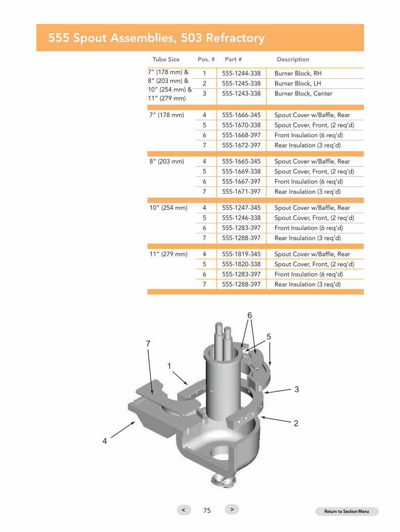
555 Spout Assemblies, 503 Refractory
Tube Size Pos. # Part # Description
7” (178 mm) 1 555-1244-338 Burner Block, RH
8” (203 mm) 2 555-1245-338 Burner Block, LH
10” (254 mm) 3 555-1243-338 Burner Block, Center
7” (178 mm) 4 555-1666-345 Spout Cover w/Baffle, Rear
5 555-1670-338 Spout Cover, Front, (2 req’d)
6 555-1668-397 Front Insulation (6 req’d)
7 555-1672-397 Rear Insulation (3 req’d)
8” (203 mm) 4 555-1665-345 Spout Cover w/Baffle, Rear
5 555-1669-338 Spout Cover, Front, (2 req’d)
6 555-1667-397 Front Insulation (6 req’d)
7 555-1671-397 Rear Insulation (3 req’d)
10” (254 mm) 4 555-1247-345 Spout Cover w/Baffle, Rear
5 555-1246-338 Spout Cover, Front, (2 req’d)
6 555-1283-397 Front Insulation (6 req’d)
7 555-1288-397 Rear Insulation (3 req’d)
11” (279 mm) 4 555-1819-345 Spout Cover w/Baffle, Rear
5 555-1820-338 Spout Cover, Front, (2 req’d)
6 555-1283-397 Front Insulation (6 req’d)
7 555-1288-397 Rear Insulation (3 req’d)
7” (178 mm) &8” (203 mm) &10” (254 mm) &11” (279 mm)
75

555 Spout Assemblies, 515 Refractory
Tube Size Pos. # Part # Description
10” (254 mm) & 1 555-1784-338 Burner Block, RH
11" (279 mm) 2 555-1782-338 Burner Block, LH
3 555-1783-338 Burner Block, Center
10” (254 mm) 4 555-1247-345 Spout Cover w/Baffle, Rear
5 555-1246-338 Spout Cover, Front, (2 req’d)
6 555-1283-397 Front Insulation (6 req’d)
7 555-1288-397 Rear Insulation (3 req’d)
11” (279 mm) 4 555-1819-345 Spout Cover, Rear
5 555-1820-338 Spout Cover, Front, (2 req’d)
6 555-1283-397 Front Insulation (6 req’d)
7 555-1288-397 Rear Insulation (3 req’d)
76

81 Metering Spout Assembly - 8” Tube
MeteringTube Size Pos. # Part # Description
8” 1 81-4544-338 Burner Block, RH
(203 mm) 2 81-4543-338 Burner Block, LH
3 81-4545-338 Burner Block, Center
4 81-4737-345 Spout Cover, Rear
5 81-4736-338 Spout Cover, Front
6 81-4738-397 Front Insulation (3 req’d)
7 81-4739-397 Rear Insulation (3 req’d)
Note: Tube and spout figures
shown below do not reflect
actual metering system shapes.
77

81 Metering Spout Assembly - 9” Tube
MeteringTube Size Pos. # Part # Description
9” 1 81-4544-338 Burner Block, RH
(229 mm) 2 81-4543-338 Burner Block, LH
3 81-4545-338 Burner Block, Center
4 81-4798-345 Spout Cover, Rear
5 81-4797-338 Spout Cover, Front
6 81-4738-397 Front Insulation (3 req’d)
7 81-4739-397 Rear Insulation (3 req’d)
Note: Tube and spout figures
shown below do not reflect
actual metering system shapes.
78

503 Metering Spout Assembly - 10” Tube
MeteringTube Size Pos. # Part # Description
10” 1 555-1244-338 Burner Block, RH
(254 mm) 2 555-1245-338 Burner Block, LH
3 555-1243-338 Burner Block, Center
4 555-2138-345 Spout Cover, Rear
5 555-2137-338 Spout Cover, Front, (2 req’d)
6 555-1283-397 Front Insulation (6 req’d)
7 555-1288-397 Rear Insulation (3 req’d)
Note: Tube and spout figures
shown below do not reflect
actual metering system shapes.
79

503 Metering Spout Assembly - 11” Tube
MeteringTube Size Pos. # Part # Description
11” 1 555-1244-338 Burner Block, RH
(279 mm) 2 555-1245-338 Burner Block, LH
3 555-1243-338 Burner Block, Center
4 555-2142-345 Spout Cover, Rear
5 555-2143-338 Spout Cover, Front, (2 req’d)
6 555-2144-397 Front Insulation (6 req’d)
7 555-2145-397 Rear Insulation (3 req’d)
Note: Tube and spout figures
shown below do not reflect
actual metering system shapes.
80

515 Metering Spout Assembly - 10” Tube
MeteringTube Size Pos. # Part # Description
10” 1 555-1784-338 Burner Block, RH
(254 mm) 2 555-1782-338 Burner Block, LH
3 555-1783-338 Burner Block, Center
4 555-2138-345 Spout Cover, Rear
5 555-2137-338 Spout Cover, Front, (2 req’d)
6 555-1283-397 Front Insulation (6 req’d)
7 555-1288-397 Rear Insulation (3 req’d)
Note: Tube and spout figures
shown below do not reflect
actual metering system shapes.
81

515 Metering Spout Assembly - 11” Tube
MeteringTube Size Pos. # Part # Description
11” 1 555-1784-338 Burner Block, RH
(279 mm) 2 555-1782-338 Burner Block, LH
3 555-1783-338 Burner Block, Center
4 555-2142-345 Spout Cover, Rear
5 555-2143-338 Spout Cover, Front, (2 req’d)
6 555-2144-397 Front Insulation (6 req’d)
7 555-2145-397 Rear Insulation (3 req’d)
Note: Tube and spout figures
shown below do not reflect
actual metering system shapes.
82

585 Metering Spout Assembly - 13” Tube
MeteringTube Size Pos. # Part # Description
13” 1 585-1011-338 Burner Block, RH
(330 mm) 2 585-1010-338 Burner Block, LH
3 585-1012-338 Burner Block, Center
4 585-1090-345 Spout Cover, Rear
5 585-1089-338 Spout Cover, Front, (2 req’d)
6 585-1086-397 Front Insulation (6 req’d)
7 585-1087-397 Rear Insulation (3 req’d)
Note: Tube and spout figures
shown below do not reflect
actual metering system shapes.
83

84

Plungers
Tubes
Spouts
Orifice R
ings
& Gaskets
Spout
Assem
blies
Stirrers &Rotor Seg
ments
Insulation,Cem
ents &Hard
Bricks
ForehearthMaintenance Item
s
GlasshouseCrucib
les& Accessories
TechnicalReferences
MSD
SMaterial SafetyData Sheet
USA, OWENSVILLE, MOPlant number for technical assistance Telephone +1 (573) 437 2132Ordering +1 800 243 0048
Stirrers & Rotor Segments
Superior Wear Resistance
Both stirrers and rotor segments require materials which
are designed to withstand the severe wear inherent in
the applications. This is provided by the Emhart Glass
315 and 333 compositions.
Stirrers, especially those used in colorant forehearths,
require close grinding control. This helps ensure that
when rotated in the 3-bank or 4-bank configurations,
they produce minimum runout to ensure correct
colorant mixing patterns.
Click the Section Tabs at right to navigate by section
or click the Menu below to navigate to pages in this section.
85

For special applications, alternative refractory materialsare available. Please contact your nearest Emhart Glassrepresentative.
Stirrers & Rotor SegmentsMaterial Data
301* 315 333
ZrO2 35 20 11Al2O3 45 11 73SiO2 19 69 15Density (g/cc) 3.2 3.1 3.0Porosity (%) 18 19 18MOR (MPa) 20.0 21.4 17.9
*New formula containing 35% ZrO2. Mix was launched in2011.
All data is subject to reasonable deviations and not to be usedfor specification purposes.
R.H. HelixCW
L.H. HelixCW
86
Refractory Part Numbers
123-4567- 3XXEmhart GlassPart Number
Emhart GlassMaterial
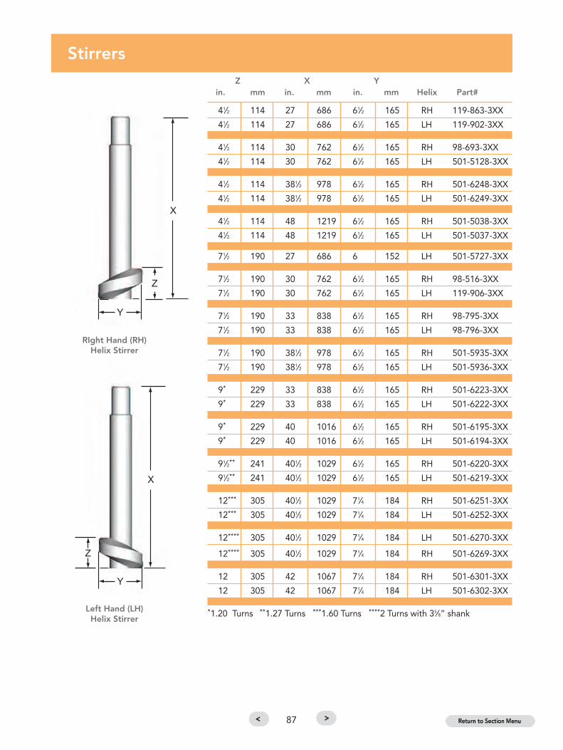
41⁄2 114 27 686 61⁄2 165 RH 119-863-3XX
41⁄2 114 27 686 61⁄2 165 LH 119-902-3XX
41⁄2 114 30 762 61⁄2 165 RH 98-693-3XX
41⁄2 114 30 762 61⁄2 165 LH 501-5128-3XX
41⁄2 114 381⁄2 978 61⁄2 165 RH 501-6248-3XX
41⁄2 114 381⁄2 978 61⁄2 165 LH 501-6249-3XX
41⁄2 114 48 1219 61⁄2 165 RH 501-5038-3XX
41⁄2 114 48 1219 61⁄2 165 LH 501-5037-3XX
71⁄2 190 27 686 6 152 LH 501-5727-3XX
71⁄2 190 30 762 61⁄2 165 RH 98-516-3XX
71⁄2 190 30 762 61⁄2 165 LH 119-906-3XX
71⁄2 190 33 838 61⁄2 165 RH 98-795-3XX
71⁄2 190 33 838 61⁄2 165 LH 98-796-3XX
71⁄2 190 381⁄2 978 61⁄2 165 RH 501-5935-3XX
71⁄2 190 381⁄2 978 61⁄2 165 LH 501-5936-3XX
9* 229 33 838 61⁄2 165 RH 501-6223-3XX
9* 229 33 838 61⁄2 165 LH 501-6222-3XX
9* 229 40 1016 61⁄2 165 RH 501-6195-3XX
9* 229 40 1016 61⁄2 165 LH 501-6194-3XX
91⁄2** 241 401⁄2 1029 61⁄2 165 RH 501-6220-3XX
91⁄2** 241 401⁄2 1029 61⁄2 165 LH 501-6219-3XX
12*** 305 401⁄2 1029 71⁄4 184 RH 501-6251-3XX
12*** 305 401⁄2 1029 71⁄4 184 LH 501-6252-3XX
12**** 305 401⁄2 1029 71⁄4 184 LH 501-6270-3XX
12**** 305 401⁄2 1029 71⁄4 184 RH 501-6269-3XX
12 305 42 1067 71⁄4 184 RH 501-6301-3XX
12 305 42 1067 71⁄4 184 LH 501-6302-3XX
*1.20 Turns **1.27 Turns ***1.60 Turns ****2 Turns with 35⁄8” shank
StirrersZ X Y
in. mm in. mm in. mm Helix Part#
RIght Hand (RH)Helix Stirrer
Left Hand (LH)Helix Stirrer
87

Stirrer SleevesL
in. mm Part #
5 127 119-1031-3XX
71⁄2 191 501-6716-3XX
131⁄2 343 119-572-3XX
T-Bar & Paddle StirrersL Total L Paddle
in. mm in. mm Type Part #
88
26 660 15 381 T-Bar 501-6112-3XX
26 660 15 381 T-Bar 501-6113-3XX
27 686 71⁄2 191 T-Bar 501-8284-3XX
27 686 71⁄2 191 T-Bar 501-8285-3XX
361⁄16 916 1113⁄16 300 T-Bar 501-8348-3XX
361⁄16 916 1113⁄16 300 T-Bar 501-8349-3XX
361⁄16 916 1113⁄16 300 T-Bar 501-8385-3XX
361⁄16 916 1113⁄16 300 T-Bar 501-8386-3XX
393⁄8 1000 1113⁄16 300 Paddle 501-8395-3XX
393⁄8 1000 1113⁄16 300 Paddle 501-8396-3XX
393⁄8 1000 1113⁄16 300 Paddle 501-8383-3XX
393⁄8 1000 1113⁄16 300 Paddle 501-8384-3XX
Paddle Stirrer
T-Bar Stirrer
Note: Stirrer sleeves are shipped in marked, matched sets of two and should
be installed as such.

89
Rotor Segments
L Spout Gapin. mm Type in. Part # Description
197⁄8 505 Deep 81-4079-3XX For 81 Feeder
205⁄8 524 Deep 81-3487-3XX with 7” Tube
19 483 Standard 81-4451-3XX
211⁄8 537 Standard 501-6721-3XX For 81 Feeder
225⁄8 575 Deep 1⁄4 501-5389-3XX with 8” Tube
225⁄8 575 Deep 1⁄2 501-6707-3XX
225⁄8 575 Deep 501-6787-3XX
21 533 Deep 1⁄4 503-5910-3XX
211⁄2 546 Deep 1⁄2 501-6786-3XX
213⁄4 553 Deep 3⁄8 501-6730-3XX
213⁄4 553 Deep 1⁄2 501-6720-3XX
22 559 Deep 1⁄4 501-6834-3XX For 503 Feeder
22 559 Deep 3⁄8 501-6819-3XX with 10” Tube
223⁄4 578 Deep 1⁄4 503-6527-3XX
223⁄4 578 Deep 1⁄4 501-6729-3XX
223⁄4 578 Deep 1⁄2 501-6701-3XX
25 635 Deep 3⁄8 501-6736-3XX
26 660 Deep 3⁄8 501-6833-3XX
Note: Rotors are shipped in marked matched sets of three, and
should be installed as such.

90

Plungers
Tubes
Spouts
Orifice R
ings
& Gaskets
Spout
Assem
blies
Stirrers &Rotor Seg
ments
Insulation,Cem
ents &Hard
Bricks
ForehearthMaintenance Item
s
GlasshouseCrucib
les& Accessories
TechnicalReferences
MSD
SMaterial SafetyData Sheet
USA, OWENSVILLE, MOPlant number for technical assistance Telephone +1 (573) 437 2132Ordering +1 800 243 0048
Insulation, Cements & Hard Bricks
High Performance Materials
The installation of the spout assembly components
requires luting and insulation materials for the orifice ring
and for the spout. Emhart Glass provides a number of
locally manufactured luting materials to assure optimum
service.
Microporous silica spout insulation kits are provided for
all Emhart Glass spouts, including the new Metering
Spout System. These spout insulation kits are used in
conjunction with granular insulation, ceramic fiber
insulation, or Emhart’s preferred insulating castable,
EmCast 25.
Click the Section Tabs at right to navigate by section
or click the Menu below to navigate to pages in this section.
91

For special applications, alternative refractory materialsare available. Please contact your nearest Emhart Glassrepresentative.
92
Refractory Part Numbers
123-4567- 3XXEmhart GlassPart Number
Emhart GlassMaterial

Materials Needed for Spout InstallationSpout
Insulation R-220Assembly Microporous Luting Anti- #312
Spout Drawing Spout Insulation EmCast 25 Cement Adhesive CementCasing Reference Style Kit 59-94657 1320-455 1320-460 1320-30
81 Spout 81-439 Std 59-94654 100 lbs. 80 lbs. 5 lbs. 80 lbs.
Deep 59-94662
144 Spout 144-21565 Std 59-94688 50 lbs. 80 lbs. 5 lbs. 80 lbs.
503 Spout 503-259 Std 59-94652 100 lbs. 80 lbs. 5 lbs. 80 lbs.
515 Spout 515-8 Std 59-94655 100 lbs. 80 lbs. 5 lbs. 80 lbs.
555 Spout 555-97 Std 59-94684 125 lbs. 80 lbs. 5 lbs. 80 lbs.
585 Spout 585-7 Std 59-94685 125 lbs. 80 lbs. 5 lbs. 80 lbs.
Cross Section Showing Installation
93
* EmCast 25 is the recommended backup insulation of Emhart Glass, replacing the previously recommendedCelatom insulation.

Co
ntai
ner
Che
mis
try
Den
sity
Po
rosi
tyM
OR
MO
RU
se L
imit
Par
t #
Des
crip
tio
nSi
zeA
l 2O
3Si
O2
ZrO
2C
aOM
gO
g/c
c%
psi
MP
a°C
Cem
ent
1320
-25
No. 3
53A C
emen
t, A
ir Set, D
ry80
lbs.
4844
----
----
----
----
1320
-30
No. 3
12 Spout Luting C
emen
t80
lbs.
5640
----
----
----
----
1320
-40
No. 3
53H C
emen
t, H
eat Se
t80
lbs.
4844
----
----
----
----
1320
-73
No. 3
53A C
emen
t, A
ir Set, W
et80
lbs.
4844
----
----
----
--16
50
1320
-455
R-220
Orific
e Ring Luting C
emen
t80
lbs.
4844
----
----
----
----
1320
-460
R-298
Anti-A
dhe
sive
Cem
ent
5 lbs.
936
----
----
----
----
Cas
tab
le
1320
-517
Insu
lating
Castable
50 lb
s.95
----
4--
0.4
--60
04.1
1760
59-946
57EmCast 25
Insu
lating
Castable
25 lb
s.40
30--
23--
0.4
--30
0.2
1370
Loo
se F
ill
1320
-470
Stop Lea
k Material
100 lbs.
99--
----
----
----
----
1320
-110
Celatom M
P-87 for Sp
out In
sulation
50 lb
s.6.5
90--
----
0.4
----
----
1380
-30
Celatom M
N-411
for Orific
e Ring In
sul.
50 lb
s.6
84--
----
0.2
----
----
Fib
er
1380
-86
Fibrous
Refractory W
ool - Bulk Pac
king
25 lb
s.45
53--
----
----
----
1260
5106
-Ceram
ic Fiber Rope
--45
54--
----
----
----
1260
Cla
y
500-15
060-E83
Ring C
lay, Fine
500 lbs.
3261
----
----
----
----
500-15
060-38
6Ring C
lay, C
oarse
500 lbs.
3261
----
----
----
----
500-15
066-38
4Lu
ting
Clay, W
et12
5 lbs.
3063
----
----
----
----
All data is sub
ject to rea
sona
ble dev
iations
and
not to be us
ed for sp
ecifica
tion purpose
s.
Insu
lati
on,
Cem
ents
& H
ard
Bri
cks
94

Co
ntai
ner
Che
mis
try
Den
sity
Po
rosi
tyM
OR
MO
RU
se L
imit
Par
t #
Des
crip
tio
nSi
zeA
l 2O
3Si
O2
ZrO
2C
aOM
gO
g/c
c%
psi
MP
a°C
Fib
er In
sula
tio
n B
oar
d
1830-16025-394
1x24x48" Soluble Fiber Insulation Bd.
6 pcs
--75
----
230.2
--70
0.5
1260
1830-16026-394
2x24x48" Soluble Fiber Insulation Bd.
3 pcs
--75
----
230.2
--70
0.5
1260
1830-16025-396
1x24x48" RCF Insulation Board
6 pcs
3550
15--
--0.4
--125
0.9
1426
1830-16026-396
2x24x48" RCF Insulation Board
3 pcs
3550
15--
--0.4
--125
0.9
1426
1830-16025-397
1x24x48" RCF Insulation Board
6 pcs
4355
--5
--0.4
--200
1.4
1260
1830-16026-397
2x24x48" RCF Insulation Board
3 pcs
4355
--5
--0.4
--200
1.4
1260
Bri
ck In
sula
ting
Fir
ebri
ck
2460-360
9 x 41⁄2x 11⁄4" Split, 2300°F IFB
4532
64--
----
0.6
--100
0.7
1260
2460-370
9 x 41⁄2x 2" Split, 2300°F IFB
--32
64--
----
0.6
--100
0.7
1260
2460-380
9 x 41⁄2x 21⁄2" Split, 2300°F IFB
2532
64--
----
0.6
--100
0.7
1260
2460-390
9 x 41⁄2x 3" Split, 2300°F IFB
--32
64--
----
0.6
--100
0.7
1260
2460-680
9 x 41⁄2x 11⁄4" Split, 2600°F IFB
--35
61--
----
0.7
--170
1.2
1427
2460-690
9 x 41⁄2x 2" Split, 2600°F IFB
--35
61--
----
0.7
--170
1.2
1427
2460-730
9 x 41⁄2x 21⁄2" Split, 2600°F IFB
--35
61--
----
0.7
--170
1.2
1427
2460-760
9 x 41⁄2x 3" Split, 2600°F IFB
--35
61--
----
0.7
--170
1.2
1427
Sup
er-D
uty
Fire
Bri
ck
2460-1030
9 x 41⁄2x 11⁄4" Split, Firebrick
--47
48--
----
2.3
171250
8.6
--
2460-1040
9 x 41⁄2x 2" Split, Firebrick
--47
48--
----
2.3
171250
8.6
--
2460-1050
9 x 41⁄2x 21⁄2" Split, Firebrick
--47
48--
----
2.3
171250
8.6
--
2460-1060
9 x 41⁄2x 3" Split, Firebrick
--47
48--
----
2.3
171250
8.6
--
Spec
ial
140-1296
9 x 41⁄2x 21⁄2" Split, High Alumina
--70
24--
----
2.6
181900
13.1
--
140-4235
18 x 6 x 2", Burned High Alumina
--61
30--
----
2.5
132390
16.5
--
140-4236
15 x 6 x 2", Burned High Alumina
--61
30--
----
2.5
132390
16.5
--
All data is subject to reasonable deviations and not to be used for specification purposes.
Insu
lati
on,
Cem
ents
& H
ard
Bri
cks
95

96

Plungers
Tubes
Spouts
Orifice R
ings
& Gaskets
Spout
Assem
blies
Stirrers &Rotor Seg
ments
Insulation,Cem
ents &Hard
Bricks
ForehearthMaintenance Item
s
GlasshouseCrucib
les& Accessories
TechnicalReferences
MSD
SMaterial SafetyData Sheet
USA, OWENSVILLE, MOPlant number for technical assistance Telephone +1 (573) 437 2132Ordering +1 800 243 0048
Forehearth Maintenance Items
Special Shapes for Maintenance
Proper maintenance of Emhart Glass Forehearths is critical
to ensure the good operational performance and life of
the products. Emhart Glass Forehearth maintenance items
are made to original equipment specifications and include
the following items:
• Top cooling tunnel components
• Radiation plates (cooling covers)
• Back blocks
• Damper blocks
• Mantle blocks
• Skimmer blocks
Click the Section Tabs at right to navigate by section
or click the Menu below to navigate to pages in this section.
97

For special applications, alternative refractory materialsare available. Please contact your nearest Emhart Glassrepresentative.
98
Refractory Part Numbers
123-4567- 3XXEmhart GlassPart Number
Emhart GlassMaterial

99
Spout Burner Nozzles
Size (in.) Size (mm) Part # Std. Odd Size Spout Type
1⁄4” 6.35 81-2275 X 81 (normal temp)9⁄32” 7.14 81-3198 X 81 (high temp)
#3 5.41 81-2149 X 81
#13 4.69 81-1735 X 819⁄32” 7.14 115-744 X 5035⁄16” 7.93 113-663 X 5151⁄4” 6.35 113-512 X 503/5153⁄8” 9.52 113-701 X 503/515
#3 5.41 113-702 X 555-585
Forehearth Burner Nozzles
Size (in.) Size (mm) Part # Std. Odd Size Forehearth Type
1⁄4” 6.35 144-5994 X KW 81, 510 (26”)9⁄32” 7.14 144-4668 X K-36, 510 (36”)
#3 5.41 144-5848 X KW / K-367⁄32” 5.55 144-14217 X KW / K-3619⁄64” 7.54 144-14280 X KW / K-3611⁄32” 8.73 119-965 X K-485⁄16” 7.93 63-722 X K-4817⁄64” 6.74 119-639 X K-48
#13 4.69 144-5847 X 540 (26”)
#3 5.41 144-5858 X 540 (36”)
#3 5.41 144-5858 X 540 (42”)1⁄4” 6.35 144-5994 X 540 (48”)

100
Cooling Plates
Length Width Forehearth Size Part #
14” 9” 26” 540-5340-3XX
143⁄4” 14” 36” 540-5439-3XX
20” 14” 42” 540-6018-3XX
141⁄4” 14” 48” 540-8041-3XX
141⁄4” 14” 48” 540-8031-3XX
141⁄4” 14” 54” 540-25058-3XX
141⁄4” 14” 54” 540-25059-3XX
Cooling Tunnels
Length Forehearth Size Part #
18” 26” 540-5341-3XX
9” 26” 541-33301-3XX
18” 36” 540-5129-3XX
9” 36” 540-4698-3XX
18” 42” 540-6016-3XX
9” 42” 540-6977-3XX
18” 48” 540-8061-3XX
9” 48” 540-8330-3XX
18” 54” 540-25056-3XX
Burner Gaskets
Description Unit Part #
1⁄4” Ceramic Rope 8’-10’ per burner -5106
Burner Gasket / 540 Type 1 per burner 540-5040
Burner Gasket / K Type 1 per burner 1700-136

Flue Blocks
Style Part #
540 540-5345-3XX
540 540-5097-3XX
640 541-63002-3XX
340 340-5030-3XX
340 340-5004-3XX
Damper Blocks
Style Part #
540 540-5346-3XX
540 540-5402-3XX
640 541-63003-3XX
340 340-5031-3XX
340 340-5006-3XX
340 Flue Block
640 Flue Block540 Flue Block
540 Damper Block
340 Damper Block
640 Damper Block
101

102
Back Blocks
Style Part #
26” 15-608-3XX
36” 503-5145-3XX
42” 540-6022-3XX
48” 540-8208-3XX
54” 540-25136-3XX
Mantle Blocks
Style Forehearth Channel Width Part #
540 26” 540-22210-3XX
340 26” 341-35000-3XX
540 36” 540-5048-3XX
340 36” 341-45005-3XX
540 42” 540-6023-3XX
340 42” 341-55003-3XX
540 48” 540-8097-3XX
340 48” 341-65000-3XX
540 54” 540-25137-3XX
340 54” 541-75004-3XX
Skimmer Blocks
Style Forehearth Channel Width Part #
Standard 26” 144-11482-3XX
Paneled 36” 119-937-3XX
Standard 42” 540-6024-3XX
Standard 48” 540-8098-3XX
Standard 54” 540-25138-3XX
340 Mantle Block
540 Mantle Block

Sleeves
Description Part #
Thermocouple Sleeve 540-8672-3XX
Short Sleeve 119-1031-3XX
Peep Hole Items
Description Part #
Peep Hole Plug 540-23250-3XX
Peep Hole Block 540-23251-3XX
Filler Blocks
Forehearth Channel Width Part #
26” 540-5497-3XX
36” 540-5145-3XX
42” 540-6025-3XX
48” 540-8228-3XX
54” 540-8228-3XX
Peep Hole Block
Peep Hole Plug
103

104
540 Cooling Tunnel Exhausts
Height Style Forehearth Channel Width Part #
6” 540 26” 540-5342-3XX
6” 540 36” 540-5263-3XX
8” 540 36” 540-4708-3XX
6” 540 42” 540-6017-3XX
8” 540 42” 540-6978-3XX
6” 540 48” 540-8040-3XX
8” 540 48” 540-8571-3XX
6” 540 54” 540-25269-3XX
6” 540 54” 540-25057-3XX
8” 540 54” 540-25168-3XX
8” 540 54” 540-25270-3XX
340 Cooling Tunnel Exhausts
Style Forehearth Channel Width Part #
340 36” 340-5049-3XX
340 42” 340-6003-3XX
340 48” 340-8012-3XX
Wind Entry Nozzles
Style Forehearth Channel Width Part #
340 36” 340-5009-3XX
340 42” 340-6063-3XX
340 48” 340-8027-3XX
340 54” 542-5396-3XX
340 54” 542-5297-3XX

Plungers
Tubes
Spouts
Orifice R
ings
& Gaskets
Spout
Assem
blies
Stirrers &Rotor Seg
ments
Insulation,Cem
ents &Hard
Bricks
ForehearthMaintenance Item
s
GlasshouseCrucib
les& Accessories
TechnicalReferences
MSD
SMaterial SafetyData Sheet
USA, OWENSVILLE, MOPlant number for technical assistance Telephone +1 (573) 437 2132Ordering +1 800 243 0048
Glasshouse Crucibles & Accessories
A History of Craftsmanship
Since 1927, Emhart Glass has been developing and
manufacturing high quality refractories for the glass
container industry. The Owensville plant has manufactured
refractories since it was purchased in 1980 from the Laclede
Christy Refractory Company. Laclede Christy was founded
in 1844 and built a strong reputation as a refractory maker.
Before becoming a refractory plant in 1976, the Owensville
plant had specialised in the production of glass pot
refractories. Once Emhart Glass purchased the plant, the
company closed its other refractory operations and
concentrated all production in Owensville– a setup that has
been maintained to this day.
Emhart Glass understands that the basis of superior glass
conditioning for all areas of the glass making industry is high
quality refractories. Their use in forehearth and feeder
mechanisms play crucial roles in the formation and
conditioning of the glass prior to being formed into finished
products. All Emhart refractories are formulated from the
highest quality raw materials and designed to achieve
predictable density and resistance to erosion and corrosion.
Precise PC monitoring of batching and kiln firing ensure the
highest quality performance and service life.
Click the Section Tabs at right to navigate by section
or click the Menu below to navigate to pages in this section.
105

FOMLAC (344) A fortified mullite formulation and an
excellent glass contact refractory. It represents about 70% of
all crucibles supplied to the studio shops. FOMLAC has
proven itself as an excellent material for the melting of soda
lime flint glasses in either batch or cullet form.
LC-833 (333) This is a premium AZS composition; designed
as a melting medium for a wide range of corrosive glasses,
especially those containing higher levels of metallic oxide.
About 25% of the crucibles supplied to the studio shops are
fabricated in Emhart Glass' LC-833 formulation. It is the
material of choice for a host of special glass applications.
FUSILLAC 100P (357) A fused silica formulation; a product
possessing excellent thermal shock resistance. The unique
thermal shock resistance characteristics will dissipate upon
repetitive thermal cycling through the 2000°F range. Its purity
will enable the melting of technical grade glasses without the
fear of destructive contamination.
211-XFS (381) This is a clay flux material and is the
formulation developed by Emhart Glass years ago for the
manufacture of pots. It is an excellent glass control refractory
and performs well in continuous service applications. This
material does require proper furnace management in order to
heat to operating temperature. Crucibles, fabricated from the
material, are shipped unfired and it is the responsibility of the
user to burn them into service.
All of the refractories are designed to deliver optimum
performance. Materials and processes are controlled to yield
a consistently high level of utility. The staff is a team of
professionals who are dedicated to reducing your costs
through the effective application of the product line.
Emhart Glass' commitment to your success can be seen in our
laboratory and plant facilities where people, processes and
products are brought together to meet the customer's needs.
There is complete in-house capability for raw materials
testing, process control and product development. This is
enhanced with outside technical support through the facilities
of the University of Missouri.
Founded in 1844, Laclede Christy Refractories built a strong
relationship with the glass industry. In the early 1980s,
Laclede became part of Emhart Glass. This commitment to
the glass industry provides our customers with a wealth of
proven refractory experience.
Emhart Glass offers crucibles in a wide range of compositions,
sizes, and shapes. This catalog represents only a sample of
the most popular compositions. Additional sizes and shapes,
as well as custom fabrication, are available upon request. The
most popular compositions used in glass melting crucibles for
studioshop application are as follows:
For special applications, alternative refractory materialsare available. Please contact your nearest Emhart Glassrepresentative.
106
Refractory Part Numbers
123-4567- 3XXEmhart GlassPart Number
Emhart GlassMaterial

GC-156 500-10170-3XX Flat Bottom/Flat Base 4 3 5 45⁄16 1.8 1.4 12.7 11.0
GC-28 500-10097-3XX Flat Bottom/Flat Base 8 5 7 6 3.6 2.3 17.8 15.2
GC-127 500-10129-3XX Flat Bottom/Flat Base 10 8 81⁄4 61⁄2 4.5 3.6 21.0 16.5
GC-84 500-10118-3XX Round Bottom/Flat Base 13 10 81⁄2 61⁄2 5.9 4.5 21.6 16.5
GC-197 500-10174-3XX Round Bottom/Flat Base 18 14 10 7 8.2 6.4 25.4 17.8
GC-177 500-10115-3XX Round Bottom/Flat Base 18 14 7 93⁄4 8.2 6.4 17.8 24.8
GC-87 500-10111-3XX Round Bottom/Flat Base 25 20 101⁄4 81⁄4 11.3 9.1 26.0 21.0
GC-196 500-10147-3XX Round Bottom/Pedestal Base 29 24 8 11 13.2 10.9 20.3 27.9
GC-138 500-10119-3XX Round Bottom/Flat Base 37 30 71⁄2 13 16.8 13.6 19.1 33.0
GC-80 500-10066-3XX Round Bottom/Flat Base 48 40 10 12 21.8 18.1 25.4 30.5
GC-198 500-10136-3XX Round Bottom/Pedestal Base 62 50 10 14 28.1 22.7 25.4 35.6
GC-37 500-10085-3XX Round Bottom/Pedestal Base 88 70 121⁄2 14 39.9 31.8 31.8 35.6
GC-89 500-10101-3XX Round Bottom/Flat Base 100 80 11 16 45.4 36.3 27.9 40.6
GC-39 500-10048-3XX Round Bottom/Pedestal Base 119 95 101⁄2 18 54.0 43.1 26.7 45.7
GC-165 500-10102-3XX Round Bottom/Flat Base 131 105 12 18 59.4 47.6 30.5 45.7
GC-167 500-10104-3XX Round Bottom/Flat Base 147 120 13 18 66.7 54.4 33.0 45.7
GC-93 500-10089-3XX Round Bottom/Flat Base 157 125 125⁄8 19 71.2 56.7 32.1 48.3
GC-178 500-10121-3XX Round Bottom/Flat Base 190 152 16 18 86.2 68.9 40.6 45.7
GC-71 500-10060-3XX Round Bottom/Pedestal Base 199 160 161⁄2 191⁄2 90.3 72.6 41.9 49.5
GC-94 500-10098-3XX Round Bottom/Flat Base 219 175 141⁄8 211⁄2 99.3 79.4 35.9 54.6
GC-69 500-10093-3XX Round Bottom/Pedestal Base 250 200 131⁄4 25 113.4 90.7 33.7 63.5
GC-95 500-10120-3XX Round Bottom/Flat Base 250 225 151⁄8 24 113.4 102.1 38.4 61.0
GC-189 500-10134-3XX Round Bottom/Flat Base 300 240 161⁄2 231⁄2 136.1 108.9 41.9 59.7
GC-145 500-10112-3XX Round Bottom/Flat Base 312 250 155⁄8 251⁄2 141.5 113.4 39.7 64.8
GC-135 500-10116-3XX Round Bottom/Flat Base 375 300 163⁄8 27 170.1 136.1 41.6 68.6
GC-194 500-10164-3XX Round Bottom/Flat Base 485 390 17 30 220.0 176.9 43.2 76.2
GC-98 500-10123-3XX Round Bottom/Flat Base 428 350 177⁄8 27 194.1 158.8 45.4 68.6
GC-271 500-10217-3XX Round Bottom/Pedestal Base 565 455 16 341⁄2 256.3 206.4 40.6 87.63
CruciblesImperial Measurements Metric Measurements
Theoretical Effective H D Theoretical Effective H DCrucible Part # Style/Base lbs. lbs. in. in. kg kg cm cm
Round Bottom/Flat Base Flat Bottom/Flat Base Round Bottom/Pedestal Base
107
Note: Theoretical Capacity indicates the maximum capacity of crucible assuming a glass density of 2.1 g/cc.
Effective Capacity indicates a practical working volume of 80%.
Other sizes are available, contact sales formore information.

Gathering RingsGathering Piece Wt.Rings I.D (in.) O.D. (in.) Description (lbs.) Part #
R-8-16-A 9 - 16 133⁄4 - 203⁄4 Oval Half-Ring 26 500-15143-355
9 -16 133⁄4 - 203⁄4 Oval Half-Ring 25 500-15143-357
R-8 H 8 12 Half-Ring 10 500-15138-355
8 12 Half-Ring 10.5 500-15138-357
8 12 Half-Ring 11.3 500-15138-381
R-8-1/2 H 81⁄2 111⁄2 Half-Ring 8 500-15270-355
81⁄2 111⁄2 Half-Ring 8 500-15270-357
81⁄2 111⁄2 Half-Ring 8 500-15270-381
R-10 H 10 14 Half-Ring 14 500-15201-355
10 14 Half-Ring 14 500-15201-357
10 14 Half-Ring 14 500-15201-381
R-10 W 10 14 Whole-Ring 14 500-15206-355
10 14 Whole-Ring 13 500-15206-357
10 14 Whole-Ring 15 500-15206-381
R-12 H 12 16 Half-Ring 24 500-15434-355
12 16 Half-Ring 500-15434-357
12 16 Half-Ring 500-15434-381
R-16-U 16 221⁄4 Half-Ring 51 500-15059-355
16 221⁄4 Half-Ring 57 500-15059-357
R-16-K3 16 21 Half-Ring 42 500-15367-357
R-17-C 17 231⁄2 Half-Ring 64 500-15005-355
17 231⁄2 Half-Ring 74 500-15005-357
Half Rings
108
Other sizes are available, contact sales for more information.

Gathering BallsD Spindle Thread Piece Wt.
in. mm Diameter (in.) (lbs.) Part #
50 3⁄4 0.4 500-15286-355
2 3⁄4 0.5 500-15158-355
60 3⁄4 0.5 500-15287-355
21⁄2 3⁄4 0.5 500-15162-355
70 3⁄4 0.5 500-15213-355
3 3⁄4 1 500-15159-355
31⁄2 3⁄4 1.8 500-15163-355
100 3⁄4 2 500-15234-355
41⁄2 3⁄4 3.5 500-15164-355
120 3⁄4 4 500-15228-355
130 3⁄4 5 500-15214-355
140 3⁄4 6 500-15236-355
150 3⁄4 8 500-15216-355
ClayComposition Drum Wt. (lbs.) Description Part #
Ring Clay 500 Coarse Ring Clay 500-15060-386
500 Fine Ring Clay 500-15060-E83
Luting Clay 125 500-15066-384
TileTile Piece Wt. (lbs.) Description Part #
2 x 10 x 36 55 Crucible Pedestal 500-15091-379
2 x 14 x 36 75 Crucible Pedestal 500-15090-379
2 x 18 x 24 64 Crucible Pedestal 500-15089-379
6 x 12 x 12 63 Crucible Pedestal 500-15086-379
7 x 7 x 81⁄2 32 Crucible Pedestal 500-15087-379
109

Other sizes are available, contact sales for more information.
StoppersWidth Height Piece
Stopper (in.) (in.) Wt. (lbs.) Style Description Part #
1-RC 61⁄2 13 11.8 Half Right Side 500-15016-355
1-LC 61⁄2 13 11.8 Half Left Side 500-15017-355
3-LC 7 14 10.5 Half Left Side 500-15046-355
5-FC 18 18 40 Full Single Lift Hole 500-15024-355
8-FC 15 15 27 Full Single Lift Hole 500-15027-355
9-FC 141⁄2 131⁄2 23.3 Full Single Lift Hole 500-15030-355
14-FC 14 14 24 Full Double Lift Hole 500-15036-355
15-FC 14 13 22.5 Full Double Lift Hole 500-15037-355
19-FC 131⁄4 131⁄4 21 Full Double Lift Hole 500-15038-355
19-FC 131⁄4 131⁄4 Full 5" Proof Hole 500-15376-355
19-FC 131⁄4 131⁄4 Full 6" Proof Hole 500-15332-355
28-FC 15 14 Full Single Lift Hole 500-15141-355
28-RC 71⁄2 14 Half Right Side 500-15456-355
30-FC 11 12 12 Full Single Lift Hole 500-15171-355
32-FC 13 15 25 Full Double Lift Hole 500-15202-355
46-FC 18 161⁄2 Full Single Lift Hole 500-15432-355
48-FC 161⁄2 16 Full Single Lift Hole 500-15334-355
Full Stopper Half Stopper
110

Pot Plugs Plug Diameter (in.) Piece Wt.Pot Plugs Max. Min. Length (lbs.) Description Part #
3 3 21⁄4 43⁄4 2.3 7⁄8” Hole 500-15042-355
6 4 3 51⁄2 3.5 7⁄8” Hole 500-15045-355
Dog Stones/ Punty RestsDog Stones/ Width Height Piece Wt.Punty Rests (in.) (in.) (lbs.) Description Part #
Dog Stone 37⁄8 37⁄8 1.5 2 Step Rest 500-15065-355
Punty Rest 23⁄4 15⁄8 0.3 1 Step Rest 500-15078-355
Dog Stone Punty Rest
111

112
Plungers
Tubes
Spouts
Orifice R
ings
& Gaskets
Spout
Assem
blies
Stirrers &Rotor Seg
ments
Insulation,Cem
ents &Hard
Bricks
ForehearthMaintenance Item
s
GlasshouseCrucib
les& Accessories
TechnicalReferences
MSD
SMaterial SafetyData Sheet
USA, OWENSVILLE, MOPlant number for technical assistance Telephone +1 (573) 437 2132Ordering +1 800 243 0048
Technical References
Click the Section Tabs at right to navigate by section
or click the Menu below to navigate to pages in this section.
113
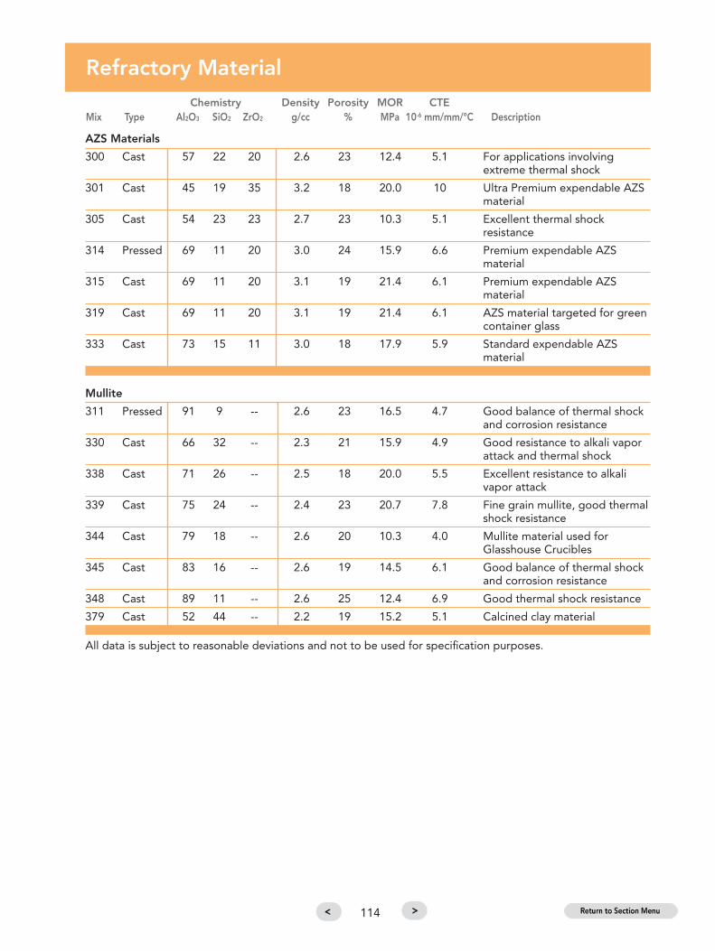
AZS Materials
300 Cast 57 22 20 2.6 23 12.4 5.1 For applications involvingextreme thermal shock
301 Cast 45 19 35 3.2 18 20.0 10 Ultra Premium expendable AZSmaterial
305 Cast 54 23 23 2.7 23 10.3 5.1 Excellent thermal shockresistance
314 Pressed 69 11 20 3.0 24 15.9 6.6 Premium expendable AZSmaterial
315 Cast 69 11 20 3.1 19 21.4 6.1 Premium expendable AZSmaterial
319 Cast 69 11 20 3.1 19 21.4 6.1 AZS material targeted for greencontainer glass
333 Cast 73 15 11 3.0 18 17.9 5.9 Standard expendable AZSmaterial
Mullite
311 Pressed 91 9 -- 2.6 23 16.5 4.7 Good balance of thermal shock and corrosion resistance
330 Cast 66 32 -- 2.3 21 15.9 4.9 Good resistance to alkali vaporattack and thermal shock
338 Cast 71 26 -- 2.5 18 20.0 5.5 Excellent resistance to alkali vapor attack
339 Cast 75 24 -- 2.4 23 20.7 7.8 Fine grain mullite, good thermalshock resistance
344 Cast 79 18 -- 2.6 20 10.3 4.0 Mullite material used forGlasshouse Crucibles
345 Cast 83 16 -- 2.6 19 14.5 6.1 Good balance of thermal shock and corrosion resistance
348 Cast 89 11 -- 2.6 25 12.4 6.9 Good thermal shock resistance
379 Cast 52 44 -- 2.2 19 15.2 5.1 Calcined clay material
All data is subject to reasonable deviations and not to be used for specification purposes.
Refractory MaterialChemistry Density Porosity MOR CTE
Mix Type Al2O3 SiO2 ZrO2 g/cc % MPa 10-6 mm/mm/°C Description
114

Refractory MaterialChemistry Density Porosity MOR CTE
Mix Type Al2O3 SiO2 ZrO2 g/cc % MPa 10-6 mm/mm/°C Description
Special
320 Cast -- 33 66 3.8 16 32.4 2.4 Pure Zircon material
321 Cast 83 1 15 3.4 15 47.6 7.4 Zirconia toughened alumina
High Alumina
350 Cast 94 4 -- 2.9 18 40.7 6.9 Good thermal shock resistance
351 Cast 98 2 -- 3.7 17 38.6 8.2 High alumina
352 Cast 99 -- -- 2.9 21 24.1 -- High purity aluimina. Limitedthermal shock resistance.
390 Cast 92 7 -- 2.7 22 20.7 -- High alumina. Average thermal shock resistance.
Fused Silica
355 Cast 30 69 -- 2.0 20 5.5 1.4 Excellent resistance to thermalshock and alkali vapor attack
356 Cast 6 93 -- 1.8 17 12.4 0.5 Low thermal expansion, excellentthermal shock resistance
357 Cast -- 100 -- 1.7 18 5.9 0.046 Pure fused silica material. Excellentthermal shock resistance.
381 Cast 31 64 -- 2.0 21 4.1 3.4 Clay flux material
Phosbond
385 Cast 92 -- -- 2.9 20 20.7 7.9 92% Chemically bonded material
All data is subject to reasonable deviations and not to be used for specification purposes.
115

Refractories for Glass Contact
Clear Clear Flint Amber Green Borosilicate Floride Fiber GlassFlint Bottle Container Container Container Opal Insulation
Material Handglass Glass Glass Glass Glass Glass (C-Glass)
301 � � �311 � �
314 � � � �315 � � � �
319 �320 � �321 � � �
333 � � � � �
344 �
345 � � �
357 � � � � �
390 � �
Based on typical glass compositions and conditions. Variations in operating conditions and glass chemistry
may affect material selection.
� Standard� Premium� Special
116
Refractories by Typical Application
Orifice Rotor Spout BurnerMaterial RIngs Spouts Tubes Segments Plungers Stirrers Block Covers Crucibles Forehearth
301 � � � � � �
305 � �
311 �
314 �315 � � � � �319 � �
320 �
321 � � �
333 � � � � � �
338 � �
344 �
345 � � � � �
357 � � � �
390 � �
� Standard� Premium� Ultra Premium� Special

Feeder Reference
Feeder Type 81 503 555 585
Master List 81-465 503-250 555-100 585-1
Spout Type Std. Deep Std. Deep Std. 515 Std. 515 Std.
Assembly 81-439 81-439 81-439 81-439 504-245 515-48 555-99 585-4
Depth (top to tube seat) 7.25 10 7.25 10 11.31 13 11.31 13 13
Entrance Width 14 14 18 18 22 24 22 24 28
Equipment Size(Throat Exit Diameter) 5 5 5/7/8 5/7/8 7/10 10/12 7/10 10/12 13
Front Plate A B C D F,G H G H J,K,L
Forehearth Channel Width 26 26 26 26/36 26/36/42/48 36/42/48 36/42/48 42/48/54
Spout
Assembly 81-461 503-84 515-8 555-97 585-5
Shear Mounting Radius 14.25 17.5 19.5 21.5
Throat Location (from front plate) 8.5 10.5 10.5 12.5
Plunger Refr.
Assembly 503-246 503-246 555-56 555-56
Length w/Std. Depth Chuck 28 30 28 30 30 31.75 30 31.75 31.75
Length w/Deep Chuck 30 30
Plunger Chuck
Assembly 503-57 503-57-04 555-56 555-56
Length from Carrier Disk (Std. Depth Chuck) 18.19 18.19 21.69 21.69
Length from CarrierDisk (Deep Chuck) 23.69 23.69
117

Equalizing Section Reference
Channel
Width 26’ 36” 42” 48” 54”
Equalizing Casings
Equalizing Assembly 540-12177-00 540-13245-00 540-14128-00 540-809 540-54004-04
Width 46” 62” 72” 81” 90”
Front Plate
A 81 Refractory Std., 14” Spout 81-4612
B 81 Refractory Deep, 14” Spout 81-4613
C 81 Refractory Std., 18” Spout 81-4644
D 81 Refractory Deep, 18” Spout 81-4581
F 503 Refractory 503-6845
G 503 Refractory 503-5433
H 515 Refractory 630-1001
J 585 Refractory 585-1123
K 585 Refractory 585-1121
L 585 Refractory 585-1005
118

Standard Spout
Cross Section showing EmCast 25-515 without curb
Typical Cross Sections of Spout Assemblies
119
Standard Spout with Curb
Cross Section showing EmCast 25-515 with curb
* EmCast 25 is the recommended backup insulation of Emhart Glass, replacing the previously recommendedCelatom insulation.

120
Metering Spout
Cross Section showing EmCast 25-515 metering
* EmCast 25 is the recommended backup insulation of Emhart Glass, replacing the previously recommendedCelatom insulation.

Plungers
Tubes
Spouts
Orifice R
ings
& Gaskets
Spout
Assem
blies
Stirrers &Rotor Seg
ments
Insulation,Cem
ents &Hard
Bricks
ForehearthMaintenance Item
s
GlasshouseCrucib
les& Accessories
TechnicalReferences
MSD
SMaterial SafetyData Sheet
USA, OWENSVILLE, MOPlant number for technical assistance Telephone +1 (573) 437 2132Ordering +1 800 243 0048
Material Safety Data Sheet (MSDS)
Click the Section Tabs at right to navigate by section
or click the Menu below to navigate to pages in this section.
121

Identification of the substance/preparation & of the company/undertaking
Composition/information on ingredients
Product Name: Refractory Products
Use of the substance/preparation: Industrial applications
Company/undertaking identification:Supplier/Manufacturer: EMHART Glass Manufacturing Inc.
405 East Peach Street, PO Box 580, Owensville MO 65066 USATel: +1 573 437 2132 Fax: +1 573 437 3146
Emergency Telephone number: CHEMTREC, International: (703) 527-3887
Product Group Specific Product NameForm when shipped- Granular or Powder 1320-2, Dry Cement; 353A; 1320-40, Heat Set Cement;
1320-460, Anit-Adhesive Cement; 1320-470, Stopleak; 353,Crucilac; 1320-517, Insulating Castable; 1320-455 Orifice Ring, Luting Cement; 1320-30 Spout Luting Cement 312.
Form when shipped- Wet Mortars & Clays 382, 201N Stopper Clay; 383, 211HH Ring Clay; 384, 211FF;1320-73, Mortar; 1320-507, Cement.
Form when shipped- Unfired Shape 380, 211XU; 381, 211XFS; 395; 398, Insulating Shape; 399,Insulating Shape.
Form when shipped- Fired Shape 300, Phoenix VC-77; 305, Phoenix VC-79; 310, Buzlac; 314,Zalac (Pressed); 315, 316, Zalac; 333, 334, 833; 311, 312;327, Spallac; 342; 345, 346, Fomlac; 348, Corlac (XL, XSM,F,H,M); 349, Crystalite (90-B); 350, LC-95; 351, LC-97; 390;320, Zirlac; 317, Zircolac; 321; 325, Rublac; 330, Mullac VC;332, Crystalite CMK; 335, Mullac, Mullac Plus; 338, Hylac; 339,Crystalite CMH, CMHH, CMXH; 347, LCF Mullite; 331,Crystalite CMC; 352, LC-99; 355, Fusillac C; 356, Fusillac G;357, Fusillac P; 379, 85XH; 380, 211XU Pot Mix; 381, 211XFS;385, Alplac 92; 386, Alplac 93.
Substance/Preparation: PreparationIngredient Name/ All compositions CAS number % EC Number ClassificationFranceAluminum Oxide 1344-28-1 40 - 60 215-691-6 Not classifiedSilica, Crystalline-Quartz 14808-60-7 40 - 60 238-878-4 R49Magnesium Oxide 1309-48-4 5 - 7 215-171-9 Not classifiedTitanium Dioxide 13463-67-7 1 - 3 236-675-5 Not classifiedGermanySilica, amorphous 60676-86-0 70 - 100 262-373-8 Not classifiedZircon 14940-68-2 40 - 60 239-019-6 Not classifiedAluminum Oxide 1344-28-1 40 - 60 215-691-6 Not classifiedSilica, Crystalline-Quartz 14808-60-7 40 - 60 238-878-4 R49Zirconium Dioxide 1314-23-4 15 - 30 215-227-2 Not classifiedNatural Diatomaceous Earth 61790-53-2 5 - 7 Not classifiedMagnesium Oxide 1309-48-4 5 - 7 215-171-9 Not classifiedTitanium Dioxide 13463-67-7 1 - 3 236-675-5 Not classifiedUnited Kingdom (UK)Silica, amorphous 60676-86-0 70 - 100 262-373-8 Not classifiedZircon 14940-68-2 40 - 60 239-019-6 Not classifiedAluminum Oxide 1344-28-1 40 - 60 215-691-6 Not classifiedSilica, Crystalline-Quartz 14808-60-7 40 - 60 238-878-4 R49Zirconium Dioxide 1314-23-4 15 - 30 215-227-2 Not classifiedNatural Diatomaceous Earth 61790-53-2 5 - 7 Not classifiedMagnesium Oxide 1309-48-4 5 - 7 215-171-9 Not classifiedTitanium Dioxide 13463-67-7 1 - 3 236-675-5 Not classifiedSee section 16 for the full text of the R Phrases declared above
122

Composition/information on ingredients
Ingredient Name/ All compositions CAS number % EC Number Classification
Ingredient Name/ Specific Compositions1320-25, Dry Cement; 353A; 1320-40, Heat Set CementAluminum Oxide 1344-28-1 50 215-691-6 Not applicable.Silica, amorphous 60676-86-0 45 262-373-8 Not applicable.Titanium Dioxide 13463-67-7 2 236-675-5 Not applicable.1320-460, Anit-Adhesive, CementAluminum Oxide 1344-28-1 93 215-691-6 Not applicable.Silica, amorphous 60676-86-0 6 262-373-8 Not applicable.1320-470, Stopleak; 353, Crucilac; 1320-517, Insulating CastableAluminum Oxide 1344-28-1 >95 215-691-6 Not applicable.1320-455 Orifice Ring, Luting Cement; 1320-30 Spout Luting, Cement 312Aluminum Oxide 1344-28-1 51 - 57 215-691-6 Not applicable.Silica, amorphous 60676-86-0 41 - 47 262-373-8 Not applicable.Titanium Dioxide 13463-67-7 1 236-675-5 Not applicable.382, 201N Stopper Clay; 383, 211HH Ring Clay; 384, 211FFSilica, amorphous 60676-86-0 45 - 75 262-373-8 Not applicable.Aluminum Oxide 1344-28-1 25 - 40 215-691-6 Not applicable.Water 7732-18-5 15 - 20 231-791-2 Not applicable.Titanium Dioxide 13463-67-7 1 - 2 236-675-5 Not applicable.1320-73, Mortar; 1320-507, CementAluminum Oxide 1344-28-1 55 - 75 215-691-6 Not applicable.Silica, amorphous 60676-86-0 25 - 45 262-373-8 Not applicable.Titanium Dioxide 13463-67-7 0 - 4 236-675-5 Not applicable.380, 211XU; 381, 211XFSSilica, amorphous 60676-86-0 65 - 75 262-373-8 Not applicable.Aluminum Oxide 1344-28-1 20 - 30 215-691-6 Not applicable.Titanium Dioxide 13463-67-7 1 - 3 236-675-5 Not applicable.395Silica, amorphous (fused) 60676-86-0 76 - 94 262-373-8 Not applicable.Silica, amorphous 60676-86-0 3 - 10 262-373-8 Not applicable.Aluminum Oxide 1344-28-1 2 - 5 215-691-6 Not applicable.398, Insulating Shape; 399, Insulating ShapeAluminum Oxide 1344-28-1 45 215-691-6 Not applicable.Silica, amorphous 60676-86-0 40 262-373-8 Not applicable.Titanium Dioxide 13463-67-7 2 236-675-5 Not applicable.300, Phoenix VC-77; 305, Phoenix VC-79Aluminum Oxide 1344-28-1 40 - 60 215-691-6 Not applicable.Zirconium Dioxide 1314-23-4 15 - 25 215-227-2 Not applicable.Silica, amorphous 60676-86-0 10 - 20 262-373-8 Not applicable.310, Buzlac; 314, Zalac (Pressed); 315, 316, Zalac; 333; 334; 833Aluminum Oxide 1344-28-1 45 - 75 215-691-6 Not applicable.Zircon 14940-68-2 10 - 30 239-019-6 Not applicable.Silica, amorphous 60676-86-0 3 262-373-8 Not applicable.311, 312; 327, Spallac; 342; 345, 346, Fomlac; 348, Corlac (XL, XSM, F,H,M); 349, Crystalite (90-B); 350, LC-95;351, LC-97; 390.Aluminum Oxide 1344-28-1 80 - 98 215-691-6 Not applicable.Silica, amorphous 60676-86-0 1 - 19 262-373-8 Not applicable.320, Zirlac; 317, ZircolacZircon 14940-68-2 99 239-019-6 Not applicable.Silica, amorphous 60676-86-0 1 262-373-8 Not applicable.321Aluminum Oxide 1344-28-1 75 - 90 215-691-6 Not applicable.Zirconium Dioxide 1314-23-4 8 - 15 215-227-2 Not applicable.Silica, amorphous 60676-86-0 <5 262-373-8 Not applicable.
123

Composition/information on ingredients
Hazards Identification
Ingredient Name/ Specific Compositions CAS number % EC Number Classification325, RublacZircon 14940-68-2 52 239-019-6 Not applicable.Aluminum Oxide 1344-28-1 45 215-691-6 Not applicable.Silica, amorphous 60676-86-0 3 262-373-8 Not applicable.330, Mullac VC; 332, Crystalite CMK; 335, Mullac, Mullac Plus; 338, Hylac; 339, Crystalite CMH, CMHH,CMXH; 347, LCF MulliteAluminum Oxide 1344-28-1 65 - 80 215-691-6 Not applicable.Silica, amorphous 60676-86-0 20 - 35 262-373-8 Not applicable.Titanium Dioxide 13463-67-7 0 - 2 236-675-5 Not applicable.331, Crystalite CMCAluminum Oxide 1344-28-1 60 - 70 215-691-6 Not applicable.Silica, amorphous 60676-86-0 25 - 35 262-373-8 Not applicable.Magnesium Oxide 1309-48-4 2 - 10 215-171-9 Not applicable.352, LC-99Aluminum Oxide 1344-28-1 >99 215-691-6 Not applicable.355, Fusillac C; 356, Fusillac GSilica, amorphous 60676-86-0 65 - 95 262-373-8 Not applicable.Aluminum Oxide 1344-28-1 5 - 30 215-691-6 Not applicable.357, Fusillac PSilica, amorphous (fused) 60676-86-0 >98 262-373-8 Not applicable.379, 85XH; 380, 211XU Pot Mix; 381, 211XFSSilica, amorphous 60676-86-0 37 - 70 262-373-8 Not applicable.Aluminum Oxide 1344-28-1 25 - 55 215-691-6 Not applicable.Titanium Dioxide 13463-67-7 1 - 3 236-675-5 Not applicable.385, Alplac 92; 386, Alplac 93Aluminum Oxide 1344-28-1 >90 215-691-6 Not applicable.Magnesium Oxide 1309-48-4 <5 215-171-9 Not applicable.Silica, amorphous 60676-86-0 0.1 - 1 262-373-8 Not applicable.
In all products listed above, Alumina and silica are mostly found as alumina-silicate (Mullite, Kaolin); as for zirconia, they contain free silica. Freesilica can be fused but is mostly found in amorphous and/or crystalline forms such as quartz, cristobalite and tridymite.* Occupational Exposure Limit(s), if available, are listed in Section 8
124
The preparation is classified as dangerous according to Directive 1999/45/EC and its amendments.Classification: Xn; R49Human health hazards: May cause cancer by inhalationSee section 11 for more detailed information on health effects and symptoms.
First Aid Measures
Inhalation: If inhaled, remove to fresh air. If breathing is difficult, give oxygen. If not breathing, give artificial respiration. Obtain medical attention.
Ingestion: Do not induce vomiting unless directed to do so by medical personnel. Never give anything by mouth to an unconscious person. Obtain medical attention.
Skin Contact: In case of contact, immediately flush skin with plenty of water. Removecontaminated clothing and shoes. Wash clothing before reuse. Clean shoesthoroughly before reuse. Obtain medical attention.
Eye Contact: In case of contact, immediately flush eyes with a copious amount of water for atleast 15 minutes. Get medical attention if irritation occurs.
Notes to Physician: No specific antidote, medical staff contact Poisons Information Centre.See section 11 for more detailed information on health effects and symptoms.

125
Fire-fighting Measures
Extinguishing media: Use an extinguishing agent suitable for surrounding fires.Special exposure hazards: No specific hazard.Special protective equipment Fire fighters should wear appropriate protective equipment and self-contained for fire-fighters: breathing apparatus (SCBA) with a full face-piece operated in positive pressure
mode.
Accidental Release Measures
Personal Precautions: Immediately contact emergency personnel. Keep unnecessary personnel away.Use suitable protective equipment (Section 8).
Environmental precautions Avoid dispersal of spilled material and runoff and contact with soil, waterways,and clean-up methods: drains and sewers.
If emergency personnel are unavailable vacuum or carefully scoop up spilled materials and place in an appropriate container for disposal. Avoid creatingdusty conditions and prevent wind dispersal.
Note: see section 8 for personal protective equipment and section 13 for waste disposal.
Handling and Storage
Handling: Do not ingest. Wash thoroughly after handling.Storage: Keep container tightly closed. Keep container in a cool, well-ventilated area.Packaging Materials Recommended: Use original container.Specific Uses: Not available.
Exposure Controls/ Personal Protection
Ingredient Name Occupational Exposure LimitsFranceAluminum Oxide INRS (France, 6/2004).
VME: 10 mg/m3 8 hour(s). Form: All formsSilica, Crystalline-Quartz INRS (France, 6/2004).
VME: 0,1 mg/m3 8 hour(s). Form: Respirable fractionMagnesium Oxide INRS (France, 1999).
VME: 10 mg/m3 8 hour(s). Form: FumeVME: 10 mg/m3 8 hour(s). Form: All forms
Titanium Dioxide INRS (France, 1999).VME: 10 mg/m3 8 hour(s). Form: DustVME: 10 mg/m3 8 hour(s). Form: Respirable fraction
GermanySilica, amorphous MAK-Werte Liste (Germany, 7/2004).
TWA: 0,3 mg/m3 8 hour(s). Form: Respirable fractionTRGS900 MAK (Germany, 5/2004).TWA: 0,3 mg/m3 8 hour(s). Form: Respirable fraction
Zircon MAK-Werte Liste (Germany, 7/2004).Spitzenbegrenzung: 1 mg/m3 15 minute(s). Form: Inhalable fractionTWA: 1 mg/m3 8 hour(s). Form: Inhalable fraction

Exposure Controls/ Personal Protection
Ingredient Name Occupational Exposure LimitsGermanyZircon TRGS900 MAK (Germany, 5/2004).
TWA: 1 mg/m3 8 hour(s). Form: Inhalable fractionAluminum Oxide MAK-Werte Liste (Germany, 7/2004).
Spitzenbegrenzung: 12 mg/m3 15 minute(s). Form: Respirable fractionTWA: 1,5 mg/m3 8 hour(s). Form: Respirable fraction
Silica, Crystalline - Quartz TRGS900 MAK (Germany, 5/2004).TWA: 0,15 mg/m3 8 hour(s). Form: Respirable fraction
Zirconium Dioxide MAK-Werte Liste (Germany, 7/2004).Spitzenbegrenzung: 1 mg/m3 15 minute(s). Form: Inhalable fractionTWA: 1 mg/m3 8 hour(s). Form: Inhalable fractionTRGS900 MAK (Germany, 5/2004).TWA: 1 mg/m3 8 hour(s). Form: Inhalable fraction
Natural Diatomaceous Earth MAK-Werte Liste (Germany, 2000).TWA: 4 mg/m3 8 hour(s). Form: Inhalable fraction.TWA: 4 mg/m3 8 hour(s). Form: Inhalable fractionTRGS900 MAK (Germany, 5/2004).TWA: 4 mg/m3 8 hour(s). Form: Inhalable fraction
Magnesium Oxide MAK-Werte Liste (Germany, 2000).TWA: 4 mg/m3 8 hour(s). Form: Inhalable fraction.TWA: 1,5 mg/m3 8 hour(s). Form: Respirable fractionTWA: 4 mg/m3 8 hour(s). Form: Inhalable fractionTWA: 1,5 mg/m3 8 hour(s). Form: Respirable fraction
Titanium Dioxide MAK-Werte Liste (Germany, 7/2004).TWA: 1,5 mg/m3 8 hour(s). Form: Respirable fraction
United Kingdom (UK)Silica, amorphous EH40-OES (United Kingdom (UK), 5/2003).
TWA: 6 mg/m3 8 hour(s). Form: Inhalable fractionTWA: 0,08 mg/m3 8 hour(s). Form: Respirable fraction
Zircon EH40-OES (United Kingdom (UK), 5/2003).STEL: 10 mg/m3 15 minute(s). Form: All formsTWA: 5 mg/m3 8 hour(s). Form: All forms
Aluminum Oxide EH40-OES (United Kingdom (UK), 5/2003).TWA: 10 mg/m3 8 hour(s). Form: Inhalable fractionTWA: 4 mg/m3 8 hour(s). Form: Respirable fraction
Silica, Crystalline-Quartz EH40-MEL (United Kingdom (UK), 5/2003).TWA: 0,3 mg/m3 8 hour(s). Form: Respirable fraction
Zirconium Dioxide EH40-OES (United Kingdom (UK), 5/2003).STEL: 10 mg/m3 15 minute(s). Form: All formsTWA: 5 mg/m3 8 hour(s). Form: All forms
Natural Diatomaceous Earth EH40-OES (United Kingdom (UK), 5/2003).TWA: 6 mg/m3 8 hour(s). Form: Inhalable fractionTWA: 1,2 mg/m3 8 hour(s). Form: Respirable fraction
Magnesium Oxide EH40-OES (United Kingdom (UK), 5/2003).STEL: 10 mg/m3 15 minute(s). Form: Respirable fractionTWA: 10 mg/m3 8 hour(s). Form: Inhalable fractionTWA: 4 mg/m3 8 hour(s). Form: Respirable fraction
Titanium Dioxide EH40-OES (United Kingdom (UK), 5/2003).TWA: 10 mg/m3 8 hour(s). Form: Inhalable fractionTWA: 4 mg/m3 8 hour(s). Form: Respirable fraction
126

Exposure Controls/ Personal Protection
Exposure ControlsOccupational Exposure Controls: Use process enclosures, local exhaust ventilation, or other engineering
controls to keep airborne levels below recommended exposure limits. Ifuser operations generate dust, fume or mist, use ventilation to keepexposure to airborne contaminants below the exposure limit.
Respiratory Protection: Dust respirator
Hand Protection: Natural rubber (latex)
Eye Protection: Safety glasses with side shields
Skin Protection: Lab coat
Physical and Chemical Properties
General InformationAppearancePhysical State: SolidOdour: OdourlessImportant health, safety and environmental information:pH: NeutralSolubility: Insoluble in cold water, hot water
Product Group Specific Product Name Specific Melting PointGravity
FORM WHEN SHIPPED - 1320-25, Dry Cement; 353A; 1320-40, Heat Set Cement 2.4 to 2.7 1482°C (2700°F)GRANULAR OR POWDER 1320-460, Anti-Adhesive, Cement 3.3 to 3.7 1482°C (2700°F)
1320-470, Stopleak; 353, Crucilac; 1320-517 3.5 to 4.0 1815°C (3300°F)1320-455 Orifice Ring, Luting Cement; 2.7 to 3.0 1482°C (2700°F)1320-30 Spout Luting, Cement 312
FORM WHEN SHIPPED - 382, 201N Stopper Clay; 383, 211HH Ring Clay; 384, 211FF 1.8 to 2.8 1482°C (2700°F)WET MORTARS & CLAYS 1320-73, Mortar; 1320-507, Cement Not available 1482°C (2700°F)
FORM WHEN SHIPPED - 380, 211XU; 381, 211XFS 1.8 to 2.0 1371°C (2500°F)UNFIRED SHAPE 395 1.9 to 2.0 1537°C (2800°F)
398, Insulating Shape; 399, Insulating Shape 1.8 to 2.2 1537°C (2800°F)
FORM WHEN SHIPPED - 300, Phoenix VC-77 ; 305, Phoenix VC-79 3.3 to 4.0 1482°C (2700°F)FIRED SHAPE 310, Buzlac; 314, Zalac (Pressed); 315, 316, Zalac; 333, 334, 3.3 to 4.0 1482°C (2700°F)
833 311, 312; 327, Spallac; 342; 345, 346, Fomlac; 348, Corlac (XL, XSM, F,H,M); 349, Crystalite (90-B); 350, LC-95; 351, LC-97; 3.3 to 3.8 1482°C (2700°F)390 320, Zirlac; 317, Zircolac321325, Rublac 3.5 to 3.8 1482°C (2700°F)330, Mullac VC; 332, Crystalite CMK; 335, Mullac, Mullac Plus; 3.3 to 4.0 1482°C (2700°F)338, Hylac; 339, Crystalite CMH, CMHH, CMXH; 347, LCF 3.8 to 4.2 1371°C (2500°F)Mullite 331, Crystalite CMC 3.0 to 3.3 1482°C (2700°F)352, LC-99 2.7 to 3.1 1315°C (2400°F)355, Fusillac C;356, Fusillac G 3.7 to 3.9 1482°C (2700°F)357, Fusillac P 2.2 to 2.6 1482°C (2700°F)379, 85XH; 380, 211XU Pot Mix; 381, 211XFS 2.2 to 2.6 1482°C (2700°F)385, Alplac 92; 386, Alplac 93 1.8 to 2.9 1371°C (2500°F)
3.4 to 3.8 1482°C (2700°F)
127

Stability and Reactivity
Stability: The product is stable.Conditions to Avoid: None known.Materials to Avoid: Inert material.
Toxicological Information
Potential acute health effectsInhalation: May cause cancer by inhalation.Ingestion: No known significant effects or critical hazards.Skin Contact: No known significant effects or critical hazards.Eye Contact: No known significant effects or critical hazards.Carcinogenicity: No known significant effects or critical hazards.Mutagenicity: No known significant effects or critical hazards.Reproductive Toxicity: No known significant effects or critical hazards.Denmark – Carcinogen list: Contains substance(s) listed under National Working Environment
Authorities Executive Order 140/1997.
Over-exposure signs/symptomsInhalation: No known significant effects or critical hazards.Ingestion: No known significant effects or critical hazards.Skin: No known significant effects or critical hazards.Target Organs: Contains material which causes damage to the following organs: lungs,
upper respiratory tract.Other adverse effects: Not available.
Ecological Information
Ecotoxicity DataIngredient Name Species Period ResultTitanium Dioxide Daphnia magna (EC50) 48 hour(s) >1000 mg/l
Mobility: Not available.Other adverse effects: No known significant effects or critical hazards.
Disposal Considerations
Methods of Disposal: The generation of waste should be avoided or minimised wherever possible.Avoid dispersal of spilled material and runoff and contact with soil, waterways, drains and sewers. Disposal of this product, solutions and any by-products should at all times comply with the requirements of environmental protection and waste disposal legislation and any regional local authority requirements.
Waste Classification: Not applicable.European Waste Catalogue (EWC): Not available.Hazardous Waste: The classification of the product may meet the criteria for a hazardous
waste.
128

Other Information
Full text of R phrases referred to in sections 2&3-France: R49- May cause cancer by inhalation.Full text of classifications referred to in sections 2&3-France: Xn - HarmfulFull text of R phrases referred to in sections 2&3-Germany: R49- May cause cancer by inhalation.Full text of classificationsreferred to in sections 2&3-Germany: Xn - HarmfulFull text of R phrases referred to in sections 2&3-United Kingdom (UK): R49- May cause cancer by inhalation.Full text of classifications referred to in sections 2&3-United Kingdom (UK): Xn - Harmful
HistoryDate of Issue: 02/28/2005Version: 1
Notice to Reader: To the best of our knowledge, the information contained herein is accurate. However, neither the abovenamed supplier nor any of its subsidiaries assumes any liability whatsoever for the accuracy or completeness of the informationcontained herein. Final determination of suitability of any material is the sole responsibility of the user. All materials may presentunknown hazards and should be used with caution. Although certain hazards are described herein, we cannot guarantee thatthese are the only hazards that exist.
Authored by KEMIKAPowered by ATRION
Transport Information
International transport regulationsClassification: ADR/ADN/IMDG/IATA : Not regulated.Label: Not applicable.
Regulatory Information
EU RegulationsHazard Symbol(s): Harmful
Risk Phrases: R49- May cause cancer by inhalation.Product Use: Classification and labelling have been performed according to EU directives
67/548/EEC,1999/45/EC, including amendments and the intended use. Industrial applications.
EC Statistical classification(Tariff Code): 32089091
National regulations : France - GermanyEmployment restrictions in accordance with § 15b of theHazardous Substance Ordinance: YesHazardous incident ordinance: NoOrdinance on combustible liquids: Class: OmittedHazard class for water: 3
129

Emhart Glass Worldwide PresencePrincipalEmhart Glass SAHinterbergstrasse 22CH-6330 Cham, SwitzerlandTelephone +41 (41) 749 42 00Telefax +41 (41) 749 42 [email protected]
BR0046


![Daft - Industry standard partnering agreement · INDUSTRY STANDARD PARTNERING AGREEMENT [ ] 2014 [CONTRACTOR] and [SUBCONTRACTOR] [Notes: 1. This Industry Standard Partnering Agreement,](https://img.pdfslide.net/doc/110x75/5bac0f7a09d3f24b638d0005/daft-industry-standard-partnering-agreement-industry-standard-partnering-agreement.jpg)