Embed Size (px)
Citation preview

PARTS DESCRIPTION
“Quality and Performance that sets the Standard for the World”
Physical Dimensions
Rotation 360˚Clearance 4''HookOpening 9/16''SafetyChainLength 9''SafetyChainRating 274Lbs.ToolMountingPoint 5/16''Depth 5''Diameter 7''Length 21''Weight 8.5Lbs.CableTravel 6.5FeetCableExtension 66''
7230/31 Series - Installation, Operating and Maintenance Instructions
ENGINEERING & EQUIPMENT CO., INC.
1 FloatingHangingSuspension1A Optional-CrosbyBullardHook2 SafetyChainwithShackle3 RubberBufferBall4 CableClamp5 CableWedge,Socket,&
TriggerSnapHook6 CableFerrule7 Worm—17mm8 DrumLock9 RearCoverDisk10 CableAssembly
1 2
9
8
7
3
4
106
5
2 1A
3
4
5
610
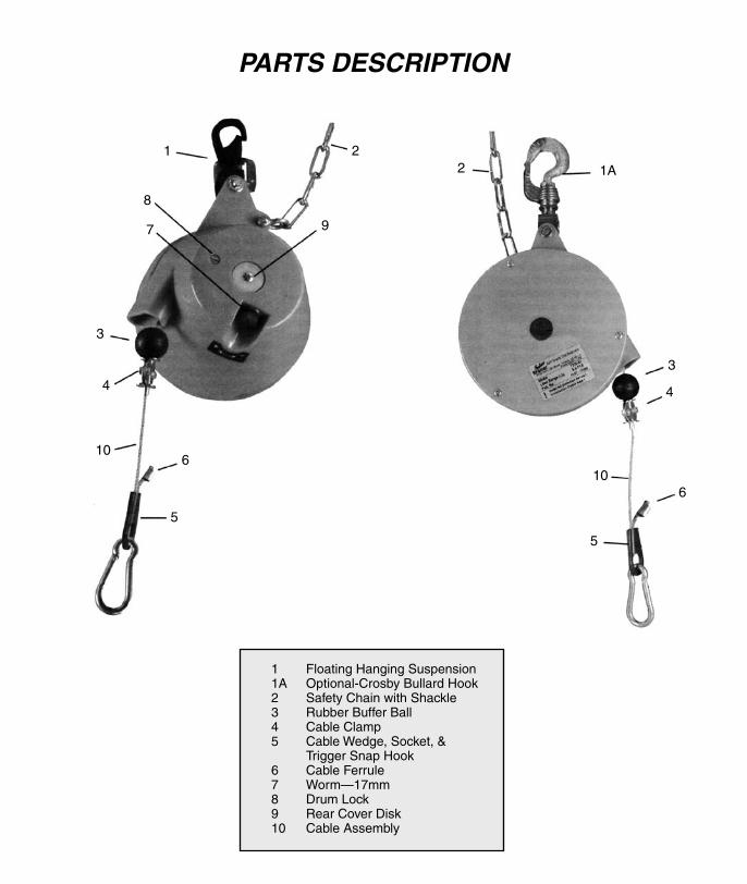
PARTS DESCRIPTION
“Quality and Performance that sets the Standard for the World”
Physical Dimensions
Rotation 360˚Clearance 4''HookOpening 9/16''SafetyChainLength 9''SafetyChainRating 274Lbs.ToolMountingPoint 5/16''Depth 5''Diameter 7''Length 21''Weight 8.5Lbs.CableTravel 6.5FeetCableExtension 66''
7230/31 Series - Installation, Operating and Maintenance Instructions
ENGINEERING & EQUIPMENT CO., INC.
1 FloatingHangingSuspension1A Optional-CrosbyBullardHook2 SafetyChainwithShackle3 RubberBufferBall4 CableClamp5 CableWedge,Socket,& TriggerSnapHook6 CableFerrule7 Worm—17mm8 DrumLock9 RearCoverDisk10 CableAssembly
1 2
9
8
7
3
4
106
5
2 1A
3
4
5
610
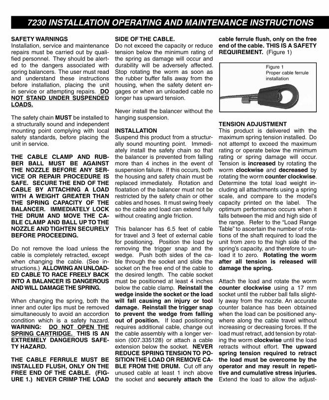
SAFETY WARNINGSInstallation,serviceandmaintenancerepairsmustbecarriedoutbyquali-fiedpersonnel.Theyshouldbealert-ed to the dangers associated withspringbalancers.Theusermustreadand understand these instructionsbefore installation, placing the unitinserviceorattempting repairs. DO NOT STAND UNDER SUSPENDED LOADS.
Thesafetychain MUSTbeinstalledtoastructurallysoundandindependentmounting point complying with localsafety standards, before placing theunitinservice.
THE CABLE CLAMP AND RUB-BER BALL MUST BE AGAINST THE NOZZLE BEFORE ANY SER-VICE OR REPAIR PROCEDURE IS SAFE. SECURE THE END OF THE CABLE BY ATTACHING A LOAD WITH A WEIGHT GREATER THAN THE SPRING CAPACITY OF THE BALANCER. IMMEDIATELY LOCK THE DRUM AND MOVE THE CA-BLE CLAMP AND BALL UP TO THE NOZZLE AND TIGHTEN SECURELY BEFORE PROCEEDING.
Do not remove the load unless thecable is completely retracted,exceptwhen changing the cable. (See in-structions.)ALLOWING AN UNLOAD-ED CABLE TO RACE FREELY BACK INTO A BALANCER IS DANGEROUS AND WILL DAMAGE THE SPRING.
When changing the spring, both theinnerandouterlipsmustberemovedsimultaneouslytoavoidanaccordioncondition which is a safety hazard.WARNING: DO NOT OPEN THE SPRING CARTRIDGE. THIS IS AN EXTREMELY DANGEROUS SAFE-TY HAZARD.
THE CABLE FERRULE MUST BE INSTALLED FLUSH, ONLY ON THE FREE END OF THE CABLE. (FIG-URE 1.) NEVER CRIMP THE LOAD
SIDE OF THE CABLE.Donotexceedthecapacityorreducetensionbelow theminimum ratingofthespringasdamagewilloccuranddurability will be adversely affected.Stop rotating the worm as soon asthe rubberbuffer fallsaway from thehousing, when the safety detent en-gagesorwhenanunloadedcablenolongerhasupwardtension.
Neverinstallthebalancerwithoutthehangingsuspension.
INSTALLATIONSuspendthisproductfromastructur-ally sound mounting point. Immedi-ately install the safety chain so thatthebalancerispreventedfromfallingmore than 4 inches in the event ofsuspensionfailure.Ifthisoccurs,boththehousingandsafetychainmustbereplaced immediately. Rotation andfloatationofthebalancermustnotberestrictedbythesafetychainorothercablesandhoses.Itmustswingfreelysothecableandloadcanextendfullywithoutcreatinganglefriction.
This balancer has 6.5 feet of cablefortraveland3feetofexternalcablefor positioning. Position the load byremoving the trigger snap and thewedge. Push both sides of the ca-ble through the socket and slide thesocketonthefreeendofthecabletothedesiredlength.Thecablesocketmustbepositionedat least4 inchesbelowthecableclamp.Reinstall the wedge inside the socket or the load will fall causing an injury or tool damage. Reinstall the trigger snap to prevent the wedge from falling out of position. If load positioningrequiresadditionalcable,changeoutthecableassemblywithalongerver-sion (007.335128) or attach a cableextensionbelowthesocket. NEVER REDUCE SPRING TENSION TO PO-SITION THE LOAD OR REMOVE CA-BLE FROM THE DRUM. Cutoffanyunused cable at least 1 inch abovethe socket and securely attach the
cable ferrule flush, only on the free end of the cable. THIS IS A SAFETY REQUIREMENT. (Figure1)
TENSION ADJUSTMENTThis product is delivered with themaximumspringtensioninstalled.Donot attempt to exceed the maximumratingoroperatebelowtheminimumrating or spring damage will occur.Tension is increased by rotating theworm clockwise and decreased byrotatingthewormcounter clockwise.Determine the total load weight in-cludingallattachmentsusingaspringscale, and compare to the model’scapacity printed on the label. Theoptimumperformanceoccurswhenitfallsbetweenthemidandhighsideoftherange.Refertothe“LoadRangeTable”toascertainthenumberofrota-tionsoftheshaftrequiredtoloadtheunit fromzerotothehighsideofthespring’scapacity,andthereforetoun-load it to zero. Rotating the worm after all tension is released will damage the spring.
Attach the loadand rotate thewormcounter clockwise using a 17 mmsocketuntiltherubberballfallsslight-lyawayfromthenozzle.Anaccuratecounter balance has been obtainedwhentheloadcanbepositionedany-where along the cable travel withoutincreasingordecreasingforces.Iftheloadmustretract,addtensionbyrotat-ingthewormclockwiseuntiltheloadretracts without effort. The upward spring tension required to retract the load must be overcome by the operator and may result in repeti-tive and cumulative stress injuries.Extend the load to allow the adjust-
ment topasscompletely through thespring.
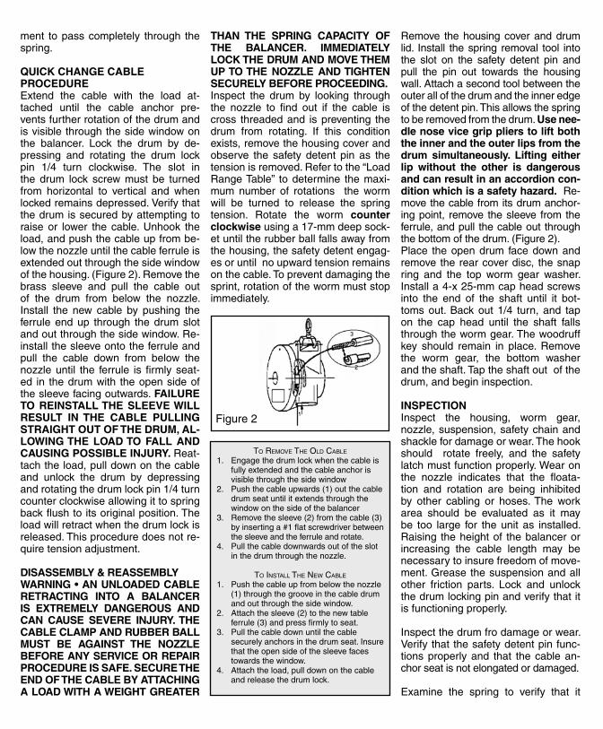
QUICK CHANGE CABLE PROCEDUREExtend the cable with the load at-tached until the cable anchor pre-ventsfurtherrotationofthedrumandisvisiblethroughthesidewindowonthe balancer. Lock the drum by de-pressing and rotating the drum lockpin 1/4 turn clockwise. The slot inthe drum lock screw must be turnedfrom horizontal to vertical and whenlockedremainsdepressed.Verifythatthedrumissecuredbyattemptingtoraise or lower the cable.Unhook theload,andpushthecableupfrombe-lowthenozzleuntilthecableferruleisextendedoutthroughthesidewindowofthehousing.(Figure2).Removethebrass sleeve and pull the cable outof the drum from below the nozzle.Install the new cable by pushing theferruleendup through thedrumslotandoutthroughthesidewindow.Re-installthesleeveontotheferruleandpull the cable down from below thenozzleuntil the ferrule is firmlyseat-ed in thedrumwith theopensideofthesleevefacingoutwards.FAILURE TO REINSTALL THE SLEEVE WILL RESULT IN THE CABLE PULLING STRAIGHT OUT OF THE DRUM, AL-LOWING THE LOAD TO FALL AND CAUSING POSSIBLE INJURY. Reat-tachtheload,pulldownonthecableand unlock the drum by depressingandrotatingthedrumlockpin1/4turncounterclockwiseallowingittospringbackflushtoitsoriginalposition.Theloadwillretractwhenthedrumlockisreleased.Thisproceduredoesnotre-quiretensionadjustment.
DISASSEMBLY & REASSEMBLYWARNING • AN UNLOADED CABLE RETRACTING INTO A BALANCER IS EXTREMELY DANGEROUS AND CAN CAUSE SEVERE INJURY. THE CABLE CLAMP AND RUBBER BALL MUST BE AGAINST THE NOZZLE BEFORE ANY SERVICE OR REPAIR PROCEDURE IS SAFE. SECURE THE END OF THE CABLE BY ATTACHING A LOAD WITH A WEIGHT GREATER
THAN THE SPRING CAPACITY OF THE BALANCER. IMMEDIATELY LOCK THE DRUM AND MOVE THEM UP TO THE NOZZLE AND TIGHTEN SECURELY BEFORE PROCEEDING.Inspect the drum by looking throughthe nozzle to find out if the cable iscross threadedand ispreventing thedrum from rotating. If this conditionexists,removethehousingcoverandobserve the safety detent pin as thetensionisremoved.Refertothe“LoadRangeTable” todetermine themaxi-mum number of rotations the wormwill be turned to release the springtension. Rotate the worm counter clockwiseusinga17-mmdeepsock-etuntiltherubberballfallsawayfromthehousing,thesafetydetentengag-esoruntilnoupwardtensionremainsonthecable.Topreventdamagingthesprint,rotationofthewormmuststopimmediately.
Remove thehousingcoveranddrumlid. Install thespring removal tool intothe slot on the safety detent pin andpull the pin out towards the housingwall.Attachasecondtoolbetweentheouterallofthedrumandtheinneredgeofthedetentpin.Thisallowsthespringtoberemovedfromthedrum.Use nee-dle nose vice grip pliers to lift both the inner and the outer lips from the drum simultaneously. Lifting either lip without the other is dangerous and can result in an accordion con-dition which is a safety hazard.Re-movethecablefromitsdrumanchor-ingpoint, remove thesleeve fromtheferrule,andpull thecableoutthroughthebottomofthedrum.(Figure2).Place theopendrum facedownandremovetherearcoverdisc, thesnapring and the top worm gear washer.Installa4-x25-mmcapheadscrewsinto the end of the shaft until it bot-tomsout.Backout1/4 turn,and tapon the cap head until the shaft fallsthroughthewormgear.Thewoodruffkey should remain in place. Removethe worm gear, the bottom washerandtheshaft.Taptheshaftoutofthedrum,andbegininspection.
INSPECTIONInspect the housing, worm gear,nozzle,suspension,safetychainandshacklefordamageorwear.Thehookshould rotate freely, and the safetylatchmustfunctionproperly.Wearonthe nozzle indicates that the floata-tion and rotation are being inhibitedby other cabling or hoses.The workarea should be evaluated as it maybe too large for theunit as installed.Raising theheightof thebalancerorincreasing the cable length may benecessarytoinsurefreedomofmove-ment.Greasethesuspensionandallother friction parts. Lock and unlockthedrumlockingpinandverifythatitisfunctioningproperly.
Inspectthedrumfrodamageorwear.Verifythatthesafetydetentpinfunc-tionsproperlyand that thecablean-chorseatisnotelongatedordamaged.
Examine the spring to verify that it
is functional.The inner lip should fitsnugly into the inner lip of the shaftandshouldnotbemorethan1/8inchlargerthantheshaft.Discardadam-aged spring in an appropriate con-tainerfordisposal.
Movethecableclampandinspecttheentirecableandreplace it if there isanysighofwear.Verify that the trig-gersnapisworkingproperlyandthatthecableferruleisinstalledcorrectly.Lubricateallwarepartsincludingthetripper snapand thecablewithacidfreegrease.Thiswillsignificantlyim-provetheirdurability.
REPLACING THE SUSPENSIONIfthesnaphookisdamagedorworn,removethecotterpinfromtheholderpin and remove the pin, holder andhook.Replacetheentiresuspension,andreinstallthepinsandcotterpins.Greaseallfrictionpartsincludingthebearingbelowthehook,thetopandbottomoftheholder,andtheholderpin.
REPLACING THE HOUSINGRemovethehangingsuspensionanddiscard thehousingshould therebeany cracks or visual damage. Thehousingandsafetychainmustalwaysbe replaced in the event of suspen-sionfailure.Itmustalsobeinspectedcarefullyfordamageintheeventofacablefailureabovetheballwherethespringandcabledrumrotatedathighspeeduntilthesafetydetentreleasedwith severe force into the housingwall. Attach the suspension to thenewhousingandverifythatthesafetychainisinstalledsecurely.
FABRICATING A CABLE ASSEMBLYThebasiccable,(007.335128)is3.0feet longer than thecableused inastandard cable assembly. All partsrequiredexcepttheferrulemaybere-used fromanoldcableassemblyororderedindividuallyasneeded.Refertotheparts’listtodeterminetheitemswhichneedtobeordered.Thebasiccablehasacableferrulecompressedon the loadsideof thecable foran-choring in the cable drum. Slid the
rubberballontothefreeendandthenattach thecableclamp6.5 feet fromthe ferrule end.Secureanewcableferrulewithoutcrimpingthecabledi-rectly below the cable clamp. Feedtheopenendofthecableupandbackdown through the socket. Install thewedge,pulltheloadandfreesideofthecabletightforcingthewedgedownintothesocketandattachthetriggersnap.Thesocketmustbeinstalledatleast4inchesbelowthecableclamp.Slipaferruleontothefreeendofthecable for use during installation andinstallthebrasssleeveontheanchorferrule.(Figure2)
REPLACING THE CABLE ASSEMBLYInstall the drum back into the hous-ing.Thenreplacethewormgear,bothtopandbottomwormgearwashers,thesnaplockandtherearcoverdisc.Installthecableassemblyandattachthesleeveontotheferrule.Insurethattheferruleisanchoredproperlyinthedrum.Rotatethedrumcounterclock-wiseuntiltheballisnearthenozzle.
REPLACING THE CABLE DRUMThe drum should be replaced if thecablegroovesaredamagedofifthereisanyelongationorsignofcrackinginthecableanchorslot.Tochangeoutadamageddrum,removetheshaftbytappingonthe4-mmcapheadscrewinstalledinthebackendoftheshaft,until it slidesoutof thedrum. Installthebottomdrumwasherontheshaftandinserttheshaftthroughthedrum.Placethebottomhousingwasherontheshaftandslide theshaft throughthehousing.
Run the balancer over and installthe bottom worm gear washer andthealignthewormandthewoodruffkeyintothekeywayontheshaft.Taplightly on the worm gear until they
slidedownontotheshaft.Insurethewoodruff key is positioned correctlyso the snap ring groove clears thetopofthewormgear.Installthesnapring, top washer and the cover discwith thenippleplaceddown into thekeywayontheshaft.Turnthebalanc-eroverandwind the cableonto thedrumuntiltherubberballistouchingthenozzle.
REPLACING THE SPRINGThecableshouldbeinstalledpriortoreplacing the spring. Match the ca-pacityofthereplacementspringwiththeversion indicatedon thehousingcover.Ifconvertingthemodelfromitspresentcapacitytoadifferentversion,thelabelmustbereplacedorthenewloadrangeshouldbepaintedonthehousing.
Pull the safety detent pin out com-pletely and secure with the springremoval tool. Place the new springnexttothehousingwiththeouterlippointingleftanddowninthemidnightposition.Turnthehousingsothattheouter lip on the drum is also in themidnightposition.Determine thepo-sitionoftheinnerliponthespringandrotatetheshafttomatchitsposition.Installthenewspringbypushingbothlipsdownintotheshaftanddrumsi-multaneously.
FINAL ASSEMBLYInstallthedrumandhousinglidsandrotatetheshaftclockwiseuntiltheballis secured against the nozzle. Referto the “Load RangeTable” to deter-mine the number of rotations of theshaft required to load the spring toits maximum capacity. The balancershouldalwaysbe loaded to thehighside, and the tension verified with aspringscalebeforereturningtheunittoservice.
7230 INSTALLATION OPERATING AND MAINTENANCE INSTRUCTIONS
To Remove The olD cable
1. Engagethedrumlockwhenthecableisfullyextendedandthecableanchorisvisiblethroughthesidewindow
2. Pushthecableupwards(1)outthecabledrumseatuntilitextendsthroughthewindowonthesideofthebalancer
3. Removethesleeve(2)fromthecable(3)byinsertinga#1flatscrewdriverbetweenthesleeveandtheferruleandrotate.
4. Pullthecabledownwardsoutoftheslotinthedrumthroughthenozzle.
To insTall The new cable
1. Pushthecableupfrombelowthenozzle(1)throughthegrooveinthecabledrumandoutthroughthesidewindow.
2. Attachthesleeve(2)tothenewtableferrule(3)andpressfirmlytoseat.
3. Pullthecabledownuntilthecablesecurelyanchorsinthedrumseat.Insurethattheopensideofthesleevefacestowardsthewindow.
4. Attachtheload,pulldownonthecableandreleasethedrumlock.
Figure2
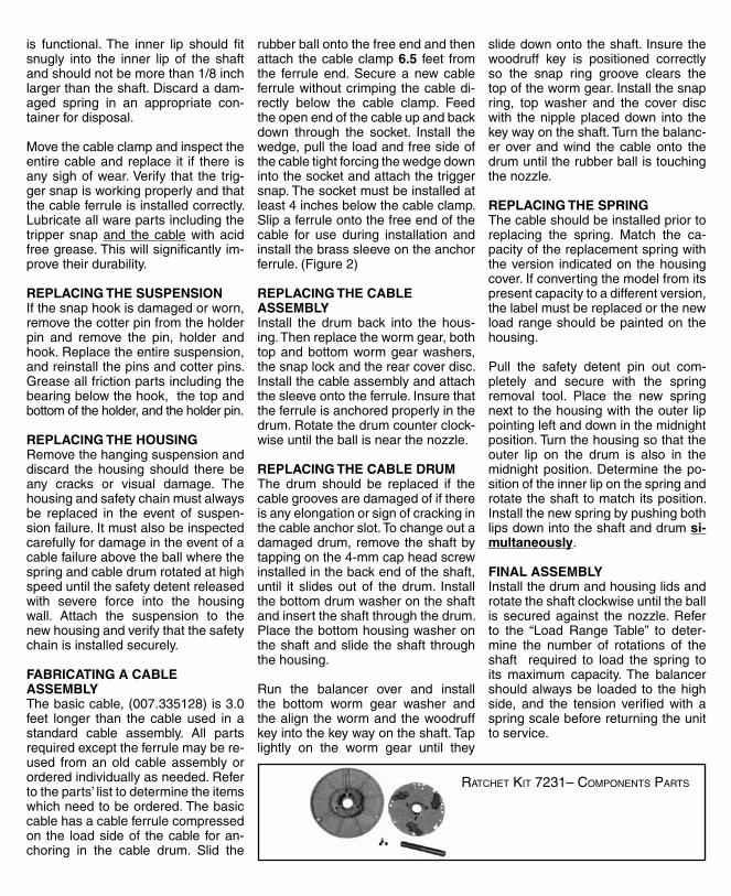
RaTcheT KiT 7231– comPonenTs PaRTs
SAFETY WARNINGSInstallation,serviceandmaintenancerepairsmustbecarriedoutbyquali-fiedpersonnel.Theyshouldbealert-ed to the dangers associated withspringbalancers.Theusermustreadand understand these instructionsbefore installation, placing the unitinserviceorattempting repairs. DO NOT STAND UNDER SUSPENDED LOADS.
Thesafetychain MUSTbeinstalledtoastructurallysoundandindependentmounting point complying with localsafety standards, before placing theunitinservice.
THE CABLE CLAMP AND RUB-BER BALL MUST BE AGAINST THE NOZZLE BEFORE ANY SER-VICE OR REPAIR PROCEDURE IS SAFE. SECURE THE END OF THE CABLE BY ATTACHING A LOAD WITH A WEIGHT GREATER THAN THE SPRING CAPACITY OF THE BALANCER. IMMEDIATELY LOCK THE DRUM AND MOVE THE CA-BLE CLAMP AND BALL UP TO THE NOZZLE AND TIGHTEN SECURELY BEFORE PROCEEDING.
Do not remove the load unless thecable is completely retracted,exceptwhen changing the cable. (See in-structions.)ALLOWING AN UNLOAD-ED CABLE TO RACE FREELY BACK INTO A BALANCER IS DANGEROUS AND WILL DAMAGE THE SPRING.
When changing the spring, both theinnerandouterlipsmustberemovedsimultaneouslytoavoidanaccordioncondition which is a safety hazard.WARNING: DO NOT OPEN THE SPRING CARTRIDGE. THIS IS AN EXTREMELY DANGEROUS SAFE-TY HAZARD.
THE CABLE FERRULE MUST BE INSTALLED FLUSH, ONLY ON THE FREE END OF THE CABLE. (FIG-URE 1.) NEVER CRIMP THE LOAD
SIDE OF THE CABLE.Donotexceedthecapacityorreducetensionbelow theminimum ratingofthespringasdamagewilloccuranddurability will be adversely affected.Stop rotating the worm as soon asthe rubberbuffer fallsaway from thehousing, when the safety detent en-gagesorwhenanunloadedcablenolongerhasupwardtension.
Neverinstallthebalancerwithoutthehangingsuspension.
INSTALLATIONSuspendthisproductfromastructur-ally sound mounting point. Immedi-ately install the safety chain so thatthebalancerispreventedfromfallingmore than 4 inches in the event ofsuspensionfailure.Ifthisoccurs,boththehousingandsafetychainmustbereplaced immediately. Rotation andfloatationofthebalancermustnotberestrictedbythesafetychainorothercablesandhoses.Itmustswingfreelysothecableandloadcanextendfullywithoutcreatinganglefriction.
This balancer has 6.5 feet of cablefortraveland3feetofexternalcablefor positioning. Position the load byremoving the trigger snap and thewedge. Push both sides of the ca-ble through the socket and slide thesocketonthefreeendofthecabletothedesiredlength.Thecablesocketmustbepositionedat least4 inchesbelowthecableclamp.Reinstall the wedge inside the socket or the load will fall causing an injury or tool damage. Reinstall the trigger snap to prevent the wedge from falling out of position. If load positioningrequiresadditionalcable,changeoutthecableassemblywithalongerver-sion (007.335128) or attach a cableextensionbelowthesocket. NEVER REDUCE SPRING TENSION TO PO-SITION THE LOAD OR REMOVE CA-BLE FROM THE DRUM. Cutoffanyunused cable at least 1 inch abovethe socket and securely attach the
cable ferrule flush, only on the free end of the cable. THIS IS A SAFETY REQUIREMENT. (Figure1)
TENSION ADJUSTMENTThis product is delivered with themaximumspringtensioninstalled.Donot attempt to exceed the maximumratingoroperatebelowtheminimumrating or spring damage will occur.Tension is increased by rotating theworm clockwise and decreased byrotatingthewormcounter clockwise.Determine the total load weight in-cludingallattachmentsusingaspringscale, and compare to the model’scapacity printed on the label. Theoptimumperformanceoccurswhenitfallsbetweenthemidandhighsideoftherange.Refertothe“LoadRangeTable”toascertainthenumberofrota-tionsoftheshaftrequiredtoloadtheunit fromzerotothehighsideofthespring’scapacity,andthereforetoun-load it to zero. Rotating the worm after all tension is released will damage the spring.
Attach the loadand rotate thewormcounter clockwise using a 17 mmsocketuntiltherubberballfallsslight-lyawayfromthenozzle.Anaccuratecounter balance has been obtainedwhentheloadcanbepositionedany-where along the cable travel withoutincreasingordecreasingforces.Iftheloadmustretract,addtensionbyrotat-ingthewormclockwiseuntiltheloadretracts without effort. The upward spring tension required to retract the load must be overcome by the operator and may result in repeti-tive and cumulative stress injuries.Extend the load to allow the adjust-
ment topasscompletely through thespring.
QUICK CHANGE CABLE PROCEDUREExtend the cable with the load at-tached until the cable anchor pre-ventsfurtherrotationofthedrumandisvisiblethroughthesidewindowonthe balancer. Lock the drum by de-pressing and rotating the drum lockpin 1/4 turn clockwise. The slot inthe drum lock screw must be turnedfrom horizontal to vertical and whenlockedremainsdepressed.Verifythatthedrumissecuredbyattemptingtoraise or lower the cable.Unhook theload,andpushthecableupfrombe-lowthenozzleuntilthecableferruleisextendedoutthroughthesidewindowofthehousing.(Figure2).Removethebrass sleeve and pull the cable outof the drum from below the nozzle.Install the new cable by pushing theferruleendup through thedrumslotandoutthroughthesidewindow.Re-installthesleeveontotheferruleandpull the cable down from below thenozzleuntil the ferrule is firmlyseat-ed in thedrumwith theopensideofthesleevefacingoutwards.FAILURE TO REINSTALL THE SLEEVE WILL RESULT IN THE CABLE PULLING STRAIGHT OUT OF THE DRUM, AL-LOWING THE LOAD TO FALL AND CAUSING POSSIBLE INJURY. Reat-tachtheload,pulldownonthecableand unlock the drum by depressingandrotatingthedrumlockpin1/4turncounterclockwiseallowingittospringbackflushtoitsoriginalposition.Theloadwillretractwhenthedrumlockisreleased.Thisproceduredoesnotre-quiretensionadjustment.
DISASSEMBLY & REASSEMBLYWARNING • AN UNLOADED CABLE RETRACTING INTO A BALANCER IS EXTREMELY DANGEROUS AND CAN CAUSE SEVERE INJURY. THE CABLE CLAMP AND RUBBER BALL MUST BE AGAINST THE NOZZLE BEFORE ANY SERVICE OR REPAIR PROCEDURE IS SAFE. SECURE THE END OF THE CABLE BY ATTACHING A LOAD WITH A WEIGHT GREATER
THAN THE SPRING CAPACITY OF THE BALANCER. IMMEDIATELY LOCK THE DRUM AND MOVE THEM UP TO THE NOZZLE AND TIGHTEN SECURELY BEFORE PROCEEDING.Inspect the drum by looking throughthe nozzle to find out if the cable iscross threadedand ispreventing thedrum from rotating. If this conditionexists,removethehousingcoverandobserve the safety detent pin as thetensionisremoved.Refertothe“LoadRangeTable” todetermine themaxi-mum number of rotations the wormwill be turned to release the springtension. Rotate the worm counter clockwiseusinga17-mmdeepsock-etuntiltherubberballfallsawayfromthehousing,thesafetydetentengag-esoruntilnoupwardtensionremainsonthecable.Topreventdamagingthesprint,rotationofthewormmuststopimmediately.
Remove thehousingcoveranddrumlid. Install thespring removal tool intothe slot on the safety detent pin andpull the pin out towards the housingwall.Attachasecondtoolbetweentheouterallofthedrumandtheinneredgeofthedetentpin.Thisallowsthespringtoberemovedfromthedrum.Use nee-dle nose vice grip pliers to lift both the inner and the outer lips from the drum simultaneously. Lifting either lip without the other is dangerous and can result in an accordion con-dition which is a safety hazard.Re-movethecablefromitsdrumanchor-ingpoint, remove thesleeve fromtheferrule,andpull thecableoutthroughthebottomofthedrum.(Figure2).Place theopendrum facedownandremovetherearcoverdisc, thesnapring and the top worm gear washer.Installa4-x25-mmcapheadscrewsinto the end of the shaft until it bot-tomsout.Backout1/4 turn,and tapon the cap head until the shaft fallsthroughthewormgear.Thewoodruffkey should remain in place. Removethe worm gear, the bottom washerandtheshaft.Taptheshaftoutofthedrum,andbegininspection.
INSPECTIONInspect the housing, worm gear,nozzle,suspension,safetychainandshacklefordamageorwear.Thehookshould rotate freely, and the safetylatchmustfunctionproperly.Wearonthe nozzle indicates that the floata-tion and rotation are being inhibitedby other cabling or hoses.The workarea should be evaluated as it maybe too large for theunit as installed.Raising theheightof thebalancerorincreasing the cable length may benecessarytoinsurefreedomofmove-ment.Greasethesuspensionandallother friction parts. Lock and unlockthedrumlockingpinandverifythatitisfunctioningproperly.
Inspectthedrumfrodamageorwear.Verifythatthesafetydetentpinfunc-tionsproperlyand that thecablean-chorseatisnotelongatedordamaged.
Examine the spring to verify that it
is functional.The inner lip should fitsnugly into the inner lip of the shaftandshouldnotbemorethan1/8inchlargerthantheshaft.Discardadam-aged spring in an appropriate con-tainerfordisposal.
Movethecableclampandinspecttheentirecableandreplace it if there isanysighofwear.Verify that the trig-gersnapisworkingproperlyandthatthecableferruleisinstalledcorrectly.Lubricateallwarepartsincludingthetripper snapand thecablewithacidfreegrease.Thiswillsignificantlyim-provetheirdurability.
REPLACING THE SUSPENSIONIfthesnaphookisdamagedorworn,removethecotterpinfromtheholderpin and remove the pin, holder andhook.Replacetheentiresuspension,andreinstallthepinsandcotterpins.Greaseallfrictionpartsincludingthebearingbelowthehook,thetopandbottomoftheholder,andtheholderpin.
REPLACING THE HOUSINGRemovethehangingsuspensionanddiscard thehousingshould therebeany cracks or visual damage. Thehousingandsafetychainmustalwaysbe replaced in the event of suspen-sionfailure.Itmustalsobeinspectedcarefullyfordamageintheeventofacablefailureabovetheballwherethespringandcabledrumrotatedathighspeeduntilthesafetydetentreleasedwith severe force into the housingwall. Attach the suspension to thenewhousingandverifythatthesafetychainisinstalledsecurely.
FABRICATING A CABLE ASSEMBLYThebasiccable,(007.335128)is3.0feet longer than thecableused inastandard cable assembly. All partsrequiredexcepttheferrulemaybere-used fromanoldcableassemblyororderedindividuallyasneeded.Refertotheparts’listtodeterminetheitemswhichneedtobeordered.Thebasiccablehasacableferrulecompressedon the loadsideof thecable foran-choring in the cable drum. Slid the
rubberballontothefreeendandthenattach thecableclamp6.5 feet fromthe ferrule end.Secureanewcableferrulewithoutcrimpingthecabledi-rectly below the cable clamp. Feedtheopenendofthecableupandbackdown through the socket. Install thewedge,pulltheloadandfreesideofthecabletightforcingthewedgedownintothesocketandattachthetriggersnap.Thesocketmustbeinstalledatleast4inchesbelowthecableclamp.Slipaferruleontothefreeendofthecable for use during installation andinstallthebrasssleeveontheanchorferrule.(Figure2)
REPLACING THE CABLE ASSEMBLYInstall the drum back into the hous-ing.Thenreplacethewormgear,bothtopandbottomwormgearwashers,thesnaplockandtherearcoverdisc.Installthecableassemblyandattachthesleeveontotheferrule.Insurethattheferruleisanchoredproperlyinthedrum.Rotatethedrumcounterclock-wiseuntiltheballisnearthenozzle.
REPLACING THE CABLE DRUMThe drum should be replaced if thecablegroovesaredamagedofifthereisanyelongationorsignofcrackinginthecableanchorslot.Tochangeoutadamageddrum,removetheshaftbytappingonthe4-mmcapheadscrewinstalledinthebackendoftheshaft,until it slidesoutof thedrum. Installthebottomdrumwasherontheshaftandinserttheshaftthroughthedrum.Placethebottomhousingwasherontheshaftandslide theshaft throughthehousing.
Run the balancer over and installthe bottom worm gear washer andthealignthewormandthewoodruffkeyintothekeywayontheshaft.Taplightly on the worm gear until they
slidedownontotheshaft.Insurethewoodruff key is positioned correctlyso the snap ring groove clears thetopofthewormgear.Installthesnapring, top washer and the cover discwith thenippleplaceddown into thekeywayontheshaft.Turnthebalanc-eroverandwind the cableonto thedrumuntiltherubberballistouchingthenozzle.
REPLACING THE SPRINGThecableshouldbeinstalledpriortoreplacing the spring. Match the ca-pacityofthereplacementspringwiththeversion indicatedon thehousingcover.Ifconvertingthemodelfromitspresentcapacitytoadifferentversion,thelabelmustbereplacedorthenewloadrangeshouldbepaintedonthehousing.
Pull the safety detent pin out com-pletely and secure with the springremoval tool. Place the new springnexttothehousingwiththeouterlippointingleftanddowninthemidnightposition.Turnthehousingsothattheouter lip on the drum is also in themidnightposition.Determine thepo-sitionoftheinnerliponthespringandrotatetheshafttomatchitsposition.Installthenewspringbypushingbothlipsdownintotheshaftanddrumsi-multaneously.
FINAL ASSEMBLYInstallthedrumandhousinglidsandrotatetheshaftclockwiseuntiltheballis secured against the nozzle. Referto the “Load RangeTable” to deter-mine the number of rotations of theshaft required to load the spring toits maximum capacity. The balancershouldalwaysbe loaded to thehighside, and the tension verified with aspringscalebeforereturningtheunittoservice.
7230 INSTALLATION OPERATING AND MAINTENANCE INSTRUCTIONS
To Remove The olD cable
1. Engagethedrumlockwhenthecableisfullyextendedandthecableanchorisvisiblethroughthesidewindow
2. Pushthecableupwards(1)outthecabledrumseatuntilitextendsthroughthewindowonthesideofthebalancer
3. Removethesleeve(2)fromthecable(3)byinsertinga#1flatscrewdriverbetweenthesleeveandtheferruleandrotate.
4. Pullthecabledownwardsoutoftheslotinthedrumthroughthenozzle.
To insTall The new cable
1. Pushthecableupfrombelowthenozzle(1)throughthegrooveinthecabledrumandoutthroughthesidewindow.
2. Attachthesleeve(2)tothenewtableferrule(3)andpressfirmlytoseat.
3. Pullthecabledownuntilthecablesecurelyanchorsinthedrumseat.Insurethattheopensideofthesleevefacestowardsthewindow.
4. Attachtheload,pulldownonthecableandreleasethedrumlock.
Figure2
RaTcheT KiT 7231– comPonenTs PaRTs