Embed Size (px)
Citation preview

PatternMaker Software
PatternMaker Version 6
TUTORIALS
PatternMaker for Windowsfor PC-compatible computers running Windows 95 and higher
Version 6PatternMaker SoftwarePO Box 70306Bellevue, WA 98007(425) 644-8161
Authors: Brian Pickrell, Jim Pickrell, Tamara VlasukRevised 2/00
Copyright 1994-2002 by PatternMaker Software.
All rights reserved. No part of this manual shall be reproduced, stored in a retrieval system, or transmitted byany means, electronic, mechanical, or otherwise, without permission from PatternMaker Software, with theexception of quoting brief passages for the purpose of reviews.

Table of Contents
PREFACE TO TUTORIALS ............................................................................................1
TUTORIAL 1: GETTING PATTERNMAKER STARTED.................................................3
Part 1: Installing PatternMaker ................................................................................................3
Part 2: Running PatternMaker..................................................................................................6
TUTORIAL 2: OPENING A DRAWING AND VIEWING IT............................................10
Open a drawing ............................................................................................................................10
TUTORIAL 3: ENTERING INPUTS...............................................................................13
Absolute coordinates....................................................................................................................13
Relative coordinates.....................................................................................................................14
Relative angle (polar coordinates)..............................................................................................15
Save your drawing .......................................................................................................................16
TUTORIAL 4: THE EDIT FUNCTIONS .........................................................................18
Moving objects .............................................................................................................................18
Selecting objects ...........................................................................................................................18
Undo a change ..............................................................................................................................20
Repeat a command.......................................................................................................................20
Grouping objects ..........................................................................................................................20
Ungrouping objects ......................................................................................................................21
More editing commands ..............................................................................................................21
Still more editing commands.......................................................................................................22
Cancel a command.......................................................................................................................22
Restoring a Drawing from Disk..................................................................................................22
TUTORIAL 5: CUT, JOIN, AND SNAP POINTS...........................................................24
Draw a line....................................................................................................................................24
Snap to Ortho ...............................................................................................................................24
Cutting an object..........................................................................................................................25
Snap to Grid .................................................................................................................................26
Joining two objects.......................................................................................................................27
Placing a point on a curve (optional)..........................................................................................28

TUTORIAL 6: POINT EDIT FUNCTIONS .....................................................................30
Move a vertex ...............................................................................................................................30
Changing the shape of an arc......................................................................................................31
Selection windows ........................................................................................................................32
TUTORIAL 7: POLYGONS, TEXT AND DIMENSION OBJECTS WITH COLORS ANDFILL PATTERNS...........................................................................................................35
Setting the drawing color ............................................................................................................35
Setting the fill pattern..................................................................................................................35
Creating a dimension line............................................................................................................36
Creating text .................................................................................................................................38
TUTORIAL 8: INTRODUCTION TO GRADING – THE RECTANGLE..........................40
Creating a grading rule ...............................................................................................................40
Create a grading table .................................................................................................................42
Grading a pattern ........................................................................................................................44
TUTORIAL 9: LAYERS.................................................................................................46
Changing the current layer .........................................................................................................47
Changing a layer name................................................................................................................47
Changing a layer's default color.................................................................................................47
Turning layers on and off............................................................................................................48
Resetting the layers ......................................................................................................................48
TUTORIAL 10: SYMBOLS AND LIBRARY FILES .......................................................50
Selecting a symbol library ...........................................................................................................50
Loading a symbol .........................................................................................................................51
Creating or redefining a symbol (Expert or Marker Versions only) ......................................52
Creating a symbol library ...........................................................................................................54
The Explode command ................................................................................................................54
TUTORIAL 11: OFFSETS, SEAM ALLOWANCES, AND FACINGS............................56
Variable seam allowance .............................................................................................................56
Change the line style ....................................................................................................................57
Snap to Offset ...............................................................................................................................58
Single seam allowance..................................................................................................................60

TUTORIAL 12: MARKERS ...........................................................................................62
Setting the Cut Ratio....................................................................................................................62
Define Marker Pieces...................................................................................................................63
Marker Mode ...............................................................................................................................63
Set Marker Area ..........................................................................................................................64
Multiply by Cut Ratio..................................................................................................................65
Arranging a Marker ....................................................................................................................65
Marker Report .............................................................................................................................68
Printing a Marker ........................................................................................................................69
WEB PAGE TUTORIALS..............................................................................................71
Elementary Tutorial #1 ...............................................................................................................73
Elementary Tutorial #2 ...............................................................................................................95
Advanced Tutorial: Design Exercises ......................................................................................116
Advanced tutorial: Grading......................................................................................................147
INDEX .........................................................................................................................151

1
PREFACE TO TUTORIALS
Welcome to the convenience of PatternMaker Software! These tutorials will help you get started withPatternMaker computer-aided design.
Work through the tutorials in order. Read the sections in the manual that apply to the subjects thetutorials are covering, too. The tutorials give you a way to get started very quickly in PatternMaker, butthey don't give a complete explanation of they subjects they cover.
TUTORIAL CONVENTIONSAs you work through these tutorials, you will notice that some words or phrases appear in differenttypefaces. Here's what it all means:
Anything you should type will be in boldface print. The names of special keys, such as the "Enter" key("Return" on some keyboards), are set aside in angle brackets. For instance:
Press <ENTER>
Anywhere you see two special keys listed together, such as
<CTRL>+<F1>
you need to hold down the first key while typing the second.
Instructions that you should do, but that aren't meant to be typed verbatim into the computer, are set asidein square brackets:
[Select point with mouse]
Messages that you will read on the screen are printed in Courier type (a font that looks like a typewriter):
Message from PatternMaker:
Sometimes a tutorial will tell you to do something that can be done in more than one way. For instance,many commands can be selected either from a menu or by selecting an icon. If you know a different wayto do something, you don't have to do it exactly the way the tutorial says. When in doubt, however,follow the directions exactly.
Note on the "Escape" key: In PatternMaker, the right mouse button has the same effect as the Escape key(<ESC>) and it's usually more convenient to use. For brevity, the tutorials will often tell you to use theEscape key, but you can use the right mouse button instead.
What to do if you get stuck:
• Make sure you are using the correct button of the mouse. If you have a three-button mouse,PatternMaker will ignore the middle button.

Preface to Tutorials
2
• Read the prompt line. See what question the computer is asking. The computer may notunderstand what you are trying to do, or it may be doing a different command than you think itis. If you want to do a new command you may need to end the current command. Try pressingthe <ESC> key a couple of times.
• Holding the mouse down and “dragging”, as done in many programs where accuracy isn’trequired, doesn’t work in PatternMaker. Use mouse clicks. For example, to draw a line clickonce at each end.
• If all else fails, read the manual. You will be pleasantly surprised at the wisdom it contains.The only purpose of the manual is to help you use the program, so don’t be afraid of it!

3
TUTORIAL 1: GETTING PATTERNMAKER STARTED
If you are used to running programs in Windows, the first part of this tutorial will be familiar to you. Ifyou have purchased the entire PatternMaker system, PatternMaker is installed on the computer when youget it and you can skip the installation. If you know how to run other programs in Windows, you canstart using PatternMaker right away because most basic operations, such as opening a file or selecting acommand, work the same way for PatternMaker as for other Windows programs.
PART 1: INSTALLING PATTERNMAKERThis tutorial assumes that you will install PatternMaker on your C: drive, in a directory called
C:\Program Files\PatternMaker Software\PatternMaker
and that your CD drive is the D: drive. If your computer is set up differently, you should already knowabout it and you can modify your commands accordingly.
Installation of PatternMaker is easy. Just follow these simple steps:
RUN THE CD BROWSER
Put the PatternMaker CD in your CD-ROM drive. If your system is set up to run CDs automatically, youcan skip to the section called “Install Components From Browser” now. If not…
Click the Start button on the taskbar, then click "Run…" and type
[Click “Start” button]
[Click “Run…]
d:demo32.exe.
(If your CD drive is not drive D:, substitute the appropriate letter.) Click the “OK” button.
[Click “OK” button]
A file dialog box opens. Select the file “pat32-ver4.dbd” and click “Open.” This runs the PatternMakerCD browser.
[Select file PAT32-VER4.DBD]
[Click “Open” button]
The main menu of the CD browser will be displayed.
INSTALL COMPONENTS FROM BROWSER
Click the button labeled “Install Products”
[Click “Install Products” button]Now you see the Installation menu. Move the mouse over the buttons and notice that you get a

Tutorial 1: Getting PatternMaker Started
4
description of what each button does. There are several things here you can install, but for now we’reonly concerned with the PatternMaker program and perhaps a garment collection.
Move your mouse over the button to the right of the words “PatternMaker Version 4.” After you’ve readthe description, go ahead and click the button.
[Click button labeled “View Options”]
There are two options for installing the PatternMaker program. Choose one now:
1) IF YOU ARE USING THE DEMO:
Click the button to the right of the words “Program With Demo Macros.”
[Click button labled “Install Now”]
This will launch the PatternMaker Setup program. Setup installs PatternMaker and a set of demomacros onto your hard drive.
Skip now to the section below called “Install PatternMaker.”
2) IF YOU ARE USING A PURCHASED VERSION:
Click the button to the right of the words “Program Only (No Macros)”
[Click button labled “Install Now”]
This will launch the PatternMaker Setup program. Setup installs the PatternMaker program onlyonto your hard drive. We will be installing the macros (garment collections) in a later step.
Continue now to the section below called “Install PatternMaker.”
INSTALL PATTERNMAKER
The first screen you see is a Welcome message. Read it, then click the “Next” button.
[Click the “Next” button]
The next screen asks where you want PatternMaker to be installed. By default, PatternMaker expects tofind all necessary files in the folder called
C:\Program Files\Patternmaker Software\PatternMaker
If this is okay, click the “Next” button. We recommend that you do this. If you prefer to installPatternMaker in a different folder or on a different drive, click the “Browse” button and specify theproper folder.
[Click the “Next” button]
The next screen is asking about creating a folder on your Start menu. The default is to create a foldercalled “PatternMaker.” Again, we recommend that you accept this default, and click the “Next” button.

Tutorial 1: Getting PatternMaker Started
5
[Click the “Next” button]
The final screen confirms the information you have entered. Click the “Next” button one more time tobegin copying the files to your hard drive.
[Click the “Next” button]
After the files have been copied, you will see a message that the setup process is complete. You willhave the option of running PatternMaker immediately, but you don’t want to do this just yet. Leave thecheck box blank (unchecked) and click the “Finish” button.
[Click the “Finish” button]
You will now return to the CD brower.
RETURN TO CD BROWSER
Again, you have a choice to make, depending on whether you are using the demo or purchased version ofthe program:
1) IF YOU ARE USING THE DEMO:
If you’re using the demo, you’re done with the installation! Exit the CD browser:
[Click the button labled “Main Menu”]
[Click the button labled “Exit”]
[Click the button labled “Exit”]
Continue with the tutorial by skipping to the section below called “Running PatternMaker.”
2) IF YOU ARE USING A PURCHASED VERSION:
Your final step is to install any garment collections (macros) that you have purchased. You mayhave purchased macro sets alone, or you may have the Women’s Vol. 1 which comes with theHome, Expert and Marker versions.
Go back to the Installation menu:
[Click the button labled “Return To Installation Menu”]
Click the button to the right of the words “Add-On Garment Collections”
[Click the button labled “View Options”]
Click the button corresponding to the macro collection(s) you have purchased.
[Click button labled “Install Now”]

Tutorial 1: Getting PatternMaker Started
6
Confirm the folder where the macros will be installed. The default for the macros is the same asthe default for the PatternMaker program. We recommend that you accept the default.
[Confirm installation path]
[Click the “Unzip” button]
Each macro collection is protected by a password. Your PatternMaker package includes a pieceof paper with the password printed on it. Use this to install the macros.
Note: the macro passwords are case-sensitive, and must be entered exactly as shown.
[Enter macro password]
[Click the “OK” button]
The macros will unzip, and you will see a message box with a confirmation. Click “OK” thenclose the Unzip dialog box, if it is still open.
[Click “OK” button]
[Click “Close” button]
You will now return once again to the CD browser. Exit the CD browser:
[Click the button labled “Main Menu”]
[Click the button labled “Exit”]
[Click the button labled “Exit”]
Continue with the next section called “Running PatternMaker.”
PART 2: RUNNING PATTERNMAKERAfter you have installed PatternMaker, you start it, like any other Windows program, by selecting its iconfrom the Start/Programs menu.
[Select Windows “Start” button on the taskbar]
[Select “Programs”]
[Select “PatternMaker”]
[Select PatternMaker icon (labled “Pat32”)]
As with any Windows program, a new “window,” or rectangular area on the screen, appears when youstart PatternMaker. At the very top of the new window is a title bar with the words
PatternMaker

Tutorial 1: Getting PatternMaker Started
7
On the far right end of this title bar are three small squares. The title bar and squares, or “buttons,” arealso standard for all Windows programs. The functions of these buttons, from left to right, are asfollows:
minimize window maximize window exit the program
EXPAND THE PATTERNMAKER WINDOW TO FULL SIZE
The program should have opened with the PatternMaker window filling the entire screen. If it did not,move the mouse to put the cursor on the center button on the title bar, the one with a small square. Clickthe left mouse button.
[Click Maximize button]
The PatternMaker window expands to fill the entire screen. Windows gives all programs the ability torun in either a partial or full screen, but you will always want to use the full screen for PatternMaker.Remember to do this every time you start PatternMaker.
When the word
Command:
appears at the bottom of the screen, PatternMaker is ready to go. Move the mouse around on the table.The cursor (a little arrow) will move around on the screen.
WHAT YOU WILL SEE
Most of the screen will be black. This is the drawing area. It won't always show the whole drawing,because with PatternMaker you can zoom in and out and pan, like a movie camera.
On the left side of the screen are the icons. These look like little pictures. Each one represents acommand. If you put the cursor on an icon and click the left mouse button, the command will run. If youmove the cursor over an icon but don’t click the mouse, you’ll see a pop-up hint that tells you the nameof the command the icon represents. If you click the right button, PatternMaker will show you a help filethat tells you about the command.
At the top of the screen is a white bar with words on it. This is the menu bar. Each word represents amenu – a list of commands. To see a menu, put the cursor on one of the words and click the left mousebutton. To hide the menu again, click the left button again somewhere away from the menu.
Below the menu bar is a black bar with words
Draw Mode Layer0
some colored boxes, and some numbers. (“Draw Mode” won’t be here if you have PatternMaker Homeor Expert version.) This is the status bar. The words and colored areas work just like icons, but you canignore them for now. The numbers indicate the position of the mouse. They are the x and y coordinatesof the cursor position. Notice that they change as you move the mouse.

Tutorial 1: Getting PatternMaker Started
8
You can do your work in PatternMaker in either inches or centimeters. The mouse coordinates willappear in whichever units you have selected. In Tutorial 2 we'll talk about how to change the units.
At the bottom of the screen is a blue bar with white printing in it. This is the prompt line. Look at itfrequently when you are using PatternMaker. It will give you messages, or prompts, telling you what youare doing and what you need to do next. Remember that the prompts scroll – this means that the bottommessage is the most recent. Right now the prompt should be
Command:
You will see this prompt every time you finish a command and PatternMaker is waiting for a newcommand. Anything you type into the computer will also appear in the prompt line.
RUN A COMMAND
Put the cursor on the icon that looks like a rectangle. Click the left mouse button. You will see aprompt:
Command:RECT
Enter a point, <ESC> to cancel:
You are now running the rectangle command. Notice that the word
RECT
appears in green letters at the right end of the status bar. This area always tells you what command youare running.
Now, move the cursor into the drawing area and click the left button again. Important: don't hold thebutton down. PatternMaker does not use the "click and drag" system that many other computer programsuse.
[Select a point with mouse]
You have just entered a point into your drawing. There are other ways to do this, which you will learn infuture tutorials, but clicking the mouse on the drawing area is the most basic way to give PatternMakerdata.
Move the mouse around the drawing area. A rectangle will follow it around. Click the left button again.
[Select a point with mouse]
You have just drawn a rectangle. You know you are done with the command because you see theprompt:
Command:
and the word RECT changes from green to purple in the status bar.

Tutorial 1: Getting PatternMaker Started
9
REPEAT A COMMAND
Click on a different point in the drawing area. PatternMaker will start the Rectangle command and usethis point as the first input. Click on a different point in the drawing area to finish the rectangle.
[Select a point with mouse]
[Select another point with mouse]
Look for the prompt:
Command:
on the command line again.
RUN A COMMAND FROM THE MENU BAR
You will now leave PatternMaker by running the EXIT command. Put the cursor on the word "File" inthe menu bar and click the left button.
[Select File menu]
A menu will appear. Look for the word "Exit." Note that the letter x is underlined. Type
X
and PatternMaker will run the Exit command. Before the program ends, a box will appear, asking thequestion
Save file NONAME.PAT?
Put the cursor on the word "No" and click the left button.
[Select "NO" button]
You have finished running PatternMaker.
Now that you know how to run PatternMaker and give commands, the other tutorials will teach you howto use those commands.

10
TUTORIAL 2: OPENING A DRAWING AND VIEWING IT
This tutorial shows you how to look at an existing PatternMaker drawing, either one that came with thePatternMaker package or one that you have created yourself. You will not draw or change anything inthis tutorial.
ZOOM and the related commands can be run by pressing some of the special keys on your keyboard.You can do this at any time – even if you're in the middle of running a different command. Therefore,these keys are known as “hot keys.” You will find this is very important when you are adding to orchanging a drawing.
If you don't have PatternMaker running already, start it as you did in Tutorial 1.
OPEN A DRAWINGUse the mouse to select the File menu, and select the OPEN command from this menu. Press the<RETURN> or <ENTER> key.
[Select File-Open]
A dialog box will appear. In the largest white area will be a list of all the PatternMaker for Windowsdrawing files in this directory. This list will look something like this:
G0641.PAT
LIBRARY.PAT
..
SUBDIR\
but it will probably be longer, depending on how many drawing files you have.
Each name ending in ".PAT" is the name of a drawing file. Use the mouse to highlight the name of adrawing file you would like to look at. Press the <RETURN> or <ENTER> key.
[Select file G0641.PAT] <RETURN>
You will see a pattern appear in the drawing area.
You can read more about using the file selection box in Chapter 3 of the manual. If you don’t understandthe organization of files on the disk, you may want to refer to a book which explains Windows conceptsin detail.
ZOOMING
Try using some of the function keys to change your view of the drawing: Take the overlay (the long thinplastic-coated strip) out of your PatternMaker package and put it across the top of your computer

Tutorial 2: Opening A Drawing And Viewing It
11
keyboard. It shows you what each special key does. Find F1 on the overlay; just above it it says "ZoomOut." Press
<F1>
and the whole drawing will get smaller. The drawing itself hasn't changed, but your view has zoomed outlike a movie camera. Press
<F2>
to zoom back in. Now put the mouse cursor on a part of the drawing you would like a closer look at.Press <F3>
[Position mouse cursor]
<F3>
and the view will zoom in on that spot.
PANNING
<Arrow key>
The arrow keys will move your view left, right, up, or down without changing the size of the picture.Use any or all of the following keys a few times, to get a feel for them:
<F1> <F2> <F3> <F9> <PG UP> <PG DOWN> <HOME> <END> <↑↑↑↑><↓↓↓↓> <←←←←> <→→→→>
When you are done, press
<END>
This is the ZOOM ALL command and it centers the entire drawing in the drawing area.
OTHER FUNCTION KEYS
<F4> will display the grid. The dots you see are one inch or one centimeter apart (until you setthem to something different). If no dots appear, you need to zoom, either in or out, untilthe dots appear. Pressing the <F4> key again will hide the grid.
<F5> will display the vertices that the objects in your drawing are made up of. An "X" appearsat each vertex. Pressing <F5> again will hide the vertices.
<F7> will hide or show the grading arrows in your drawing, as well as their names. Thereprobably aren’t any grading arrows in your drawing. Don't worry about it for now.

Tutorial 3: Opening A Drawing And Viewing It
12
Other F keys have functions that don't change the way your drawing looks on the screen. You will learnabout these later.
You can also perform most of the same zoom functions by clicking the mouse on the zoom icons thatappear when you are running other commands. The next tutorial lets you practice this.
CHANGE YOUR WORKING UNITS
When you first start PatternMaker, the program is set to work in inches. However, if you prefer to workin centimeters, it's easy to change. Click on the box that shows the mouse coordinates (you learnedwhere this is in Tutorial 1).
[click on mouse coordinates]
A dialog box will open, showing a list of measurement units you can choose from. Select "centimeters"and then click the "OK" button.
[select "centimeters"]
[click "OK" button]
Now, as you move the mouse around, the position of the cursor is indicated in centimeters rather thaninches. Turn on the grid, if it isn't on already.
<F4>
The dots you see are one centimeter apart. (Use <F1> or <F2> to zoom in or out, if you can't see anydots.)
Since the rest of these tutorials use inches, go ahead and change back. As you do, pay attention to whathappens to the grid.
[click on mouse coordinates]
[select "inches, no fractions"]
[click "OK" button]
Notice how the grid adjusted, so that the dots are now one inch apart, instead of one centimeter apart.
You will have noticed that there are several other measurement format options in the list. We won'tdiscuss all of these now, but you can experiment with them later if you wish. The differences areexplained in detail in the User's Manual.
Now you know how to zoom in on a detail, or zoom out to see your whole pattern. You can use the gridto see how big something is, and you can see the vertices if you need to change some of them.
You are now done with this tutorial. You can Exit the program, use OPEN to open a different drawingfile, or use the NEW command to prepare for the next tutorial.

13
TUTORIAL 3: ENTERING INPUTS
In Tutorial 1 you input the corners of a rectangle by clicking the mouse on the screen. This is the easiestway to give PatternMaker inputs. In this tutorial, we will see how to use typed inputs to enter your pointsmore precisely. We will draw a sloper: a basic size 12 back body block.
Note: this tutorial is to teach you how to enter inputs to PatternMaker; we won't be learning standardpattern drafting techniques. The numbers you will be given were precalculated; so don't be concerned ifthey seem mysterious.
First, we will draw a rectangle to form a frame for our drawing. Start PatternMaker and select the RECT(rectangle) command.
[Select RECT icon]
ABSOLUTE COORDINATESUse x and y coordinates to enter the corners of the rectangle. Type
0,0 <ENTER>
for your rectangle's first point. (The first number is the horizontal, or x, coordinate. The second is thevertical, or y, coordinate.)
Type
12,26 <ENTER>
for the second point. At this point, your prompt line will look like this:
Enter a point, <ESC> to cancel:0,0
Second point, <ESC> to cancel:12,26
Command:
TO SEE THE FULL DRAWING
You can't see much because the rectangle is mostly off the edge of the screen. Press
<END>
to center the rectangle in the drawing area. The lower left corner of the rectangle is at the origin,coordinates (0,0). You can check this by putting the cursor on this point and looking at the mousecoordinates. Don't worry if it isn't exact; your typed inputs are more precise than pointing with themouse.

Tutorial 3: Entering Inputs
14
The upper right corner of the rectangle is at (12,26). This means it is 12 inches to the right of the originand 26 inches above it.
Now start drawing the sloper, using the POLY command. The POLY icon looks like a pencil drawingsome lines. Click on it to start the POLY command.
[Select POLY icon]
ZOOMING AND PANNING WITH ICONS
Notice that the icons in the icon area have changed. The icons containing yellow x’s change snap modes,which are covered in Tutorial 5. The ones showing a movie camera and an arrow are the pan functions;the ones with arrows going in or out are zoom functions. Click the mouse on the icon with a rectangleand an arrow pointing left.
[Select Pan Left icon]
Now pan right, so the view goes back to where it was.
[Select Pan Right icon]
You can experiment with the other zoom and pan icons on your own.
Now, let’s start drawing the object. For the first point, type
1,1 <ENTER>
RELATIVE COORDINATESWe want to draw a line up the center back seam. This length is 23.75 inches. You don't want to measurefrom the origin; you want to measure from the point you just entered, so type the relative coordinates:
@0,23.75 <ENTER>
The 0 means the x distance from the first point is 0. The 23.75 means the new point is 23.75 inchesabove the previous point.
DRAW A CURVE
Now draw the neckline. Press
<ESC>
and a box will appear, titled
"Point Type Options"

Tutorial 3: Entering Inputs
15
Click the left mouse button on the line that says "Arc(X)"
[Select "Arc(X)" from box]
and you will get the prompt messages
Input next point, ESC for options Option:X arc
Input corner point of arc, ESC for options
The corner point controls the shape of a curved line. This can't be measured precisely, but you can do it"by eye." Turn the grid on.
<F4>
and use the mouse to enter a point about 1½ inches to the right of your last point and level with it. Ortype the absolute coordinates:
2.5, 24.7 <ENTER>
Move the mouse around now, and you can see a curve following it. This is the curve that will be drawnif you click the left mouse button. Instead, enter the end point by typing its absolute coordinates:
3.25, 25.5 <ENTER>
This is the point where the neck meets the shoulder. It is 2 - 1/4 inches to the right of the start of theneck curve and 3/4 inch above it.
Now we need to draw a straight line for the shoulder line. Select the "Line" point option:
<ESC>
[Select "Line"]
RELATIVE ANGLE (POLAR COORDINATES)Instead of relative x and y coordinates, you can enter a point by giving a distance and angle. Theshoulder line is 5¾ inches long, and it slopes downward at a 22 degree angle. Angles are measuredupwards from the horizontal. For instance, an angle going straight up would be 90 degrees. Since ourline goes down, its angle is -22 degrees. Use the "less-than" symbol < to indicate that the numbers youtype in represent an angle:
@5.75<-22 <ENTER>
The @ means that this, too, is a relative position.
To complete the sloper, type in the following points and select point type options where indicated:

Tutorial 3: Entering Inputs
16
<ESC>
[Select "Arc(X)"]
8, 21.75 <ENTER>
8.25, 18.36 <ENTER>
8.50, 15.90 <ENTER>
10.50, 15.60 <ENTER>
<ESC>
[Select "Line"]
10.50, 1 <ENTER>
<ESC>
To finish drawing this object, you can select either Open or Closed from the box. A closed polygon isjust like an open one, except that a line is drawn connecting the first and last points. This sloper is aclosed object. Click on the words “Done (closed)”
[Select “Done (closed)”]
to finish the command.
If you make a mistake and you get a sloper that doesn't look very good, it's okay to keep it and use it forthe rest of the tutorials. If you make a more serious mistake (such as accidentally cancelling the POLYcommand), you will probably need to start the tutorial over. There are ways to fix a mistake withPatternMaker, but you haven't learned them yet.
LINE
Mark the waistline of this sloper. Select the Line icon (a diagonal line). Type in two points:
[Select Line icon]
1, 7.75 <ENTER>
10.50, 7.75 <ENTER>
The endpoints of this line will fall exactly on the sides of the sloper.
SAVE YOUR DRAWINGSelect the SAVE command from the File menu.
[Select File-Save]
The prompt will read,
Tutorial 3: Entering Inputs
17
SAVE
and a dialog box will appear, with the names of all the existing drawing files. Don't select any of these.Instead, type
BACKSLOPER <ENTER>
and PatternMaker will save your drawing in a new file called BACKSLOPER.PAT. You can give a fileany name you want. You don’t need to type the “pat” extension; PatternMaker adds that automatically.
Don't save a drawing with a name that already exists, unless you want your new file to replace the oldone with the same name. If you do this, the previous file will be saved in a file with the extension".BAK", for instance BACKSLOPER.BAK, but if you do it twice, the old ".BAK" file will be lost.
If your drawing already has a name other than "NONAME.PAT," you can save it with the same filename. In this case the previous version of the drawing will be replaced. This is how you will savechanges to this file in the following tutorials.
You are now done with Tutorial 3. Next, you will learn ways to add to and change your drawing.

18
TUTORIAL 4: THE EDIT FUNCTIONS
In Tutorial 3 you drew a sample pattern piece consisting of two objects. In this tutorial you will usesome of the editing functions to modify your sloper. You will sample some of the functions in the Editmenu, which work on entire objects. The functions in the Points menu are also editing functions, butthey work on some of the individual points in an object, rather than the whole object. You will try someof these later.
Start PatternMaker and open the file BACKSLOPER.PAT that you created in Tutorial 3. You should seethe sloper object, the horizontal waist line you drew, and the box around them. If you don't, press
<END>
to put them in view.
MOVING OBJECTSSelect the Move icon. It looks like a hand. Click the left mouse button on it. (The MOVE command isalso in the Edit menu.)
[Select Move function]
In the prompt window you will see:
Select object, ? for help, <esc>=done:
This message appears whenever you are running a command that needs you to select one or more objects.
SELECTING OBJECTSImportant: Knowing how to select an object or objects is veryimportant in PatternMaker. In future tutorials, you will often betold to select objects. Practice the following procedure until youare comfortable with it. Read the manual paragraphs on selectingobjects (Chapter 4). They give more details than are includedhere.
Put the mouse cursor on or near the sloper object and click the left button.
[Select sloper object]
Make sure to click on one of the white lines, not in the center of the object. The object will highlight (ahighlighted object is drawn in thicker lines) and the prompt will now say,

Tutorial 4: The Edit Functions
19
Select object, ? for help, <esc>=done: *Polygon selected*
If nothing happens, you didn't click the mouse close enough to the edge of the object. If the wrong objecthighlights, click on it again and it will be un-selected. Then select the sloper object.
Note that the line inside the sloper is not highlighted. This is because it is a different object and youhaven't selected it yet. We want the waistline to stay with the sloper when we move it, so select the linetoo.
[Select horizontal line]
The computer will keep asking you to select more objects until you tell it you're done selecting. Youshould now have both the sloper and the line highlighted. Tell the computer you're finished selectingobjects by pressing the Escape key.
<ESC>
The prompt line will now say
Select object, ? for help, <ESC>=done: *Polygon selected*
Select object, ? for help, <ESC>=done: --OK--
Base point?:
PatternMaker is asking you for a reference point to calculate the movement from. Think of it as a handlethat you are attaching to the objects to carry them by. But the handle doesn't have to be on the objectsyou're moving – it can be anywhere in the drawing.
Use the left mouse button to select a point somewhere near the objects you have selected.
[Select a base point]
The next prompt will be
Destination (ESC to quit):
Move the mouse around. Remember not to hold the mouse button down. The objects you selected willmove around, too. You will see a blue-green, or cyan, line appear. This line indicates how far you havemoved the objects and is not part of the drawing. Move the mouse to the right a bit, then click the leftbutton.
[Select destination point]
The cyan line disappears and the word
Command:
appears on the prompt line, showing that you are done with the MOVE command.

Tutorial 4: The Edit Functions
20
The objects have moved a distance equal to the distance from the base point to the destination. Forinstance, if the destination is three inches to the right of the base point, the objects will have moved threeinches to the right.
Any of the points you just entered could have been selected by typing the coordinates, as you learned todo in Tutorial 3. This would give you precise control over the distance your objects moved.
UNDO A CHANGESuppose the MOVE command you just did was a mistake. You can use the UNDO command to undo thelast change you made to the drawing. Select the Undo icon now (it looks like a letter U).
[Select Undo function]
The objects you just moved will move back to their original positions. Remember that you can't undomore than one command in a row, so if you make a mistake, select the UNDO command before you doanything else.
REPEAT A COMMANDIf you want to do the MOVE command again, you don't need to select the Move icon again. Just clickthe mouse anywhere in the drawing area. The MOVE command will be selected again and it will startselecting objects. Go ahead and move the same two objects anywhere you like.
[Select and move sloper and line]
GROUPING OBJECTSSometimes you have a group of objects and you will want any change made to one of them to apply to allof them. In other words, when you select one, you want to select all of them. You can do this byforming a group. The GROUP command is found in the Symbol menu.
[Select Symbol-Group function]
Select the same two objects you selected before.
[Select sloper and line]
<ESC>
You are then prompted for a name for the group. You need to give a group a name if you plan to use theLoad From Library function (Tutorial 10) to load it into another drawing later. Don’t give this group aname; just click the “OK” button.
[Click “OK” button]

Tutorial 4: The Edit Functions
21
You have just made a group of the sloper and the line. Now, select the MOVE function and then selectthe sloper object.
[Select Move function]
[Select sloper object]
When you do this, the line is selected and highlighted as well. We don’t really want to move theseobjects, so cancel the MOVE function.
<ESC> <ESC>
UNGROUPING OBJECTSTo break the group up again, use the UNGROUP command in the Symbol menu.
[Select Symbol-Ungroup function]
[Select sloper group]
<ESC>
Now, the sloper and the line are independent objects again.
MORE EDITING COMMANDSTry the following commands from the Edit menu. All of them work in a way similar to MOVE. Thesteps you follow are:
1. Select a command.
2. Select objects by clicking the left mouse button on them.
3. Press <ESC> or click the right mouse button to finish selecting objects.
4. Give PatternMaker more information, either by entering points with themouse, making choices when asked, or typing inputs.
5. You can repeat a command by clicking the mouse in the drawing areaagain.
Read the manual sections on these commands for an explanation of each one. Like MOVE, some ofthese commands move objects around as you move the mouse. You can get a general idea of their effectsby just watching what happens as you move the mouse. Don't worry about making a mess of the drawing– you will see how to restore your drawing later in this tutorial.
ROTATE rotates a group of objects.
RESIZE makes objects larger or smaller. It can also change their shapes by resizingdifferently in the X and Y directions.

Tutorial 4: The Edit Functions
22
EXPAND makes objects larger or smaller. Unlike RESIZE, it doesn't change the shape of anobject.
ERASE erases objects from the picture.
COPY copies one or more objects. It's just like MOVE, except that you end up with anobject at the destination and an identical one in the original position.
MIRROR makes mirror-image copies of objects. The line that follows the mouse after youselect the object(s) represents the "mirror" across which the originals are reflected.
STILL MORE EDITING COMMANDSTry the following commands, too. There won't be anything to watch as you move the mouse, but they areeven simpler than MOVE.
CHANGE changes the color, fill pattern (for closed objects only), layer, (we will learn aboutlayers later) or line type (dotted line, etc.) of the selected objects. Try changing thecolor of some objects for starters.
CLOSE OBJ converts an open object to a closed object by connecting the two ends of the objectwith a line. Use the POLY command to draw an open object before you can try this.The opposite of this command is DELETE SEG., found in the Points menu.
CANCEL A COMMANDRemember that pressing <ESC> or clicking the right mouse button while you are in the middle of acommand aborts the command. Try this while moving some objects. They will jump back to theiroriginal positions and you will be prompted to select a new command. (Since many commands haveintermediate steps, sometimes you’ll need to press <ESC> more than once. This depends on thecommand you are using.)
We will cover the CUT and JOIN commands in Tutorial 5.
RESTORING A DRAWING FROM DISKIf you have experimented with all of the commands listed above, your drawing is probably a clutteredmess now. Any time you do some work, then decide you want to have your original drawing instead, youcan reload your drawing from the file it is saved in. Select the OPEN command from the File menu.
[Select File - Open]
A dialog box will appear, saying

Tutorial 4: The Edit Functions
23
Save fileC:\Program Files\PatternMaker Software\PatternMaker\BACKSLOPER.PAT?
YES NO CANCEL
You don't want to save the changes you just made, so select the “No” button with the mouse.
[Select "NO" button]
The computer now deletes your drawing from memory, but the original version is still in the file. Thebox with the file names now appears, just as it did at the beginning of this tutorial. Select the same fileyou selected before.
[Select file BACKSLOPER.PAT]
You will see the same drawing you saw the first time you opened the file. You should use the SAVEcommand periodically while you are working, to save your latest changes. Then, when you reopen yourdrawing as you just did, it will return to the way it was the last time you ran the SAVE command.
You have now finished Tutorial 4. You now know how to copy, move and rearrange the objects in yourpattern. You also know how to save your work, and how to retrieve your saved work if necessary. InTutorial 5 you will use the CUT and JOIN commands to modify your sloper. You will also learn how touse snap points to make your inputs precise.

24
TUTORIAL 5: CUT, JOIN, AND SNAP POINTS
In Tutorial 3 you drew a sample pattern piece consisting of two objects. In this tutorial we will modifyyour sloper. We will see how using snap points makes precise adjustments easy.
Start PatternMaker and open the file BACKSLOPER.PAT that you created in Tutorial 3. You should seethe sloper object, the horizontal waist line you drew, and the box around them. If you don't, press
<END>
to put them in view.
We are going to use the CUT and JOIN functions to make this sloper 2 inches shorter. First we will drawa horizontal cut line, then we will cut the sloper in two. We will move the bottom piece up 2 inches, thenwe will join the two pieces back together.
DRAW A LINESelect the Line icon. It has a diagonal line on it.
[Select Line function]
Select the first point of the line with the mouse. It should be a bit to the left of the sloper object, andslightly above the line that marks the waistline.
[Enter a point]
Now, as you move the mouse, the line will follow it around. We want to draw a perfectly horizontal line,but you may notice that it's hard to keep it from being not quite level. This is where snap points come in.
SNAP TO ORTHOHold the Ctrl key down while pressing the F5 key.
<CTRL>+<F5>
This is the Snap to Ortho command. Note that you can interrupt other commands with the Snapfunctions, just like the zoom and pan commands you learned earlier. You use Snap to Ortho to select apoint that is aligned vertically or horizontally with the last point you selected.
Move the mouse until the line following the mouse cursor is almost horizontal. A yellow X will appear.If you look closely, the line following the mouse actually goes to the yellow X, not to the mouse cursor.This is the snap point.

Tutorial 5: CUT, JOIN, and Snap Points
25
Now move the mouse up until the line following the mouse is a diagonal at approximately a 45 degreeangle. The yellow X disappears. This is because there is no ortho snap point close to the mouse.Therefore, the line follows the mouse again.
Move the mouse until the line following the cursor is vertical. Once again you will see a snap point.Snap to Ortho gives you both vertical and horizontal snaps.
Select a point to the right of the sloper object. Make sure the yellow X is showing when you click themouse, so the line you draw is a perfect horizontal. Make sure the line you draw is long enough to cutthe sloper in half.
[Select horizontal snap point]
You have now drawn a horizontal line that we will use to cut the sloper. Think of it as a scissor line.You can use any polygon object (including lines, rectangles, and circles) to cut any other polygon object,open or closed. Our line extends beyond the edges of the object it will cut in order to make sure of aclean cut.
Now that we're done with our horizontal line, we don't want the snap point interfering with whatever wedo next. To get out of snap mode, hold down the Ctrl key and press the F1 key.
<CTRL>+<F1>
CUTTING AN OBJECTSelect the Cut icon. It looks like a pair of scissors.
[Select Cut function]
A prompt will ask you to select the object to be cut. Select the sloper object by putting the mouse cursoron it and clicking the left button. Then click the right button or press <ESC>.
[Select sloper object]
<ESC>
Now a prompt will ask you to select the object to cut with. Select the line you just drew.
[Select horizontal line]
<ESC>
The prompt line should say:
Command:CUT
Select the object to be cut: *Polygon selected*
Select the object to cut with: *Polygon selected*

Tutorial 5: CUT, JOIN, and Snap Points
26
The computer now uses the line to cut the sloper. You won't see any difference yet, because the piecesare still in the same places.
Let's get rid of the cut line you just drew, since we don't need it any more. Select the ERASE commandfrom the Edit menu. You learned how to use the Edit commands in Tutorial 4, so go ahead and erase thecut line.
[Select Edit-Erase]
[Erase horizontal cut line]
Now, to shorten the sloper, we want to move the lower piece up exactly two inches. It's hard to be thatprecise with the mouse. We could do it by typing the coordinates we need, but using snap points isfaster.
First, select the MOVE command and select the bottom part of the sloper.
[Select Move command]
[Select lower sloper object]
Notice that only the rectangular piece highlights, instead of the whole sloper.
Since the line marking the waistline should stay the same distance above the hipline, we need to move ittoo. Select this line, then press <ESC> to indicate that you are finished selecting.
[Select horizontal waist line]
<ESC>
SNAP TO GRIDPress
<CTRL>+<F2>
to select Snap to Grid.After you interrupt the MOVE command with the Snap to Grid command, the prompt window willconfirm the change, then repeat the last message:
Base point?:
Snap ON, Mode = GRID
Base point?:
The grid also appears. Remember that the grid points are exactly 1 inch apart. A yellow X will appearanytime the mouse cursor is near a grid point. These snap points work much like the Snap to Orthopoints, except that a snap point appears at the nearest grid point. This will make it easy to select a baseand destination exactly 2 inches apart. Remember that it doesn't matter where the base point for yourMove is, as long as the destination is 2 inches above it:
[Select any grid point]
Tutorial 5: CUT, JOIN, and Snap Points
27
[Select grid point 2 inches above previous point]
Now the bottom piece of the sloper is moved up so it overlaps the top piece by 2 inches. We'd like torecombine them.
JOINING TWO OBJECTSSelect the JOIN command from the Edit menu.
[Select Edit-Join]
This works very much like the CUT command. Select the top part of the sloper, then <ESC>, then selectthe bottom part of the sloper, then <ESC>. Be careful not to select the waist line.
[Select top sloper object]
<ESC>
[Select bottom sloper object]
<ESC>
You have shortened your sloper by two inches. You have done it essentially the same way you wouldhave done with scissors, paper, and tape, but PatternMaker has made the process quicker and moreprecise. Once you get used to the commands and snap modes, you will be able to move and rearrangethings very quickly.
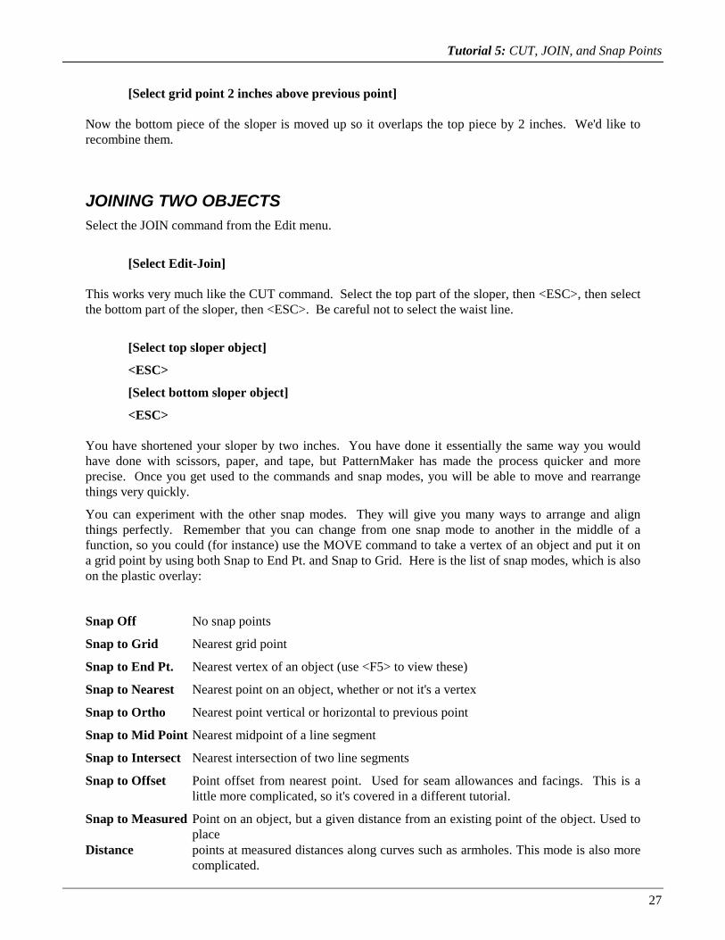
You can experiment with the other snap modes. They will give you many ways to arrange and alignthings perfectly. Remember that you can change from one snap mode to another in the middle of afunction, so you could (for instance) use the MOVE command to take a vertex of an object and put it ona grid point by using both Snap to End Pt. and Snap to Grid. Here is the list of snap modes, which is alsoon the plastic overlay:
Snap Off No snap points
Snap to Grid Nearest grid point
Snap to End Pt. Nearest vertex of an object (use <F5> to view these)
Snap to Nearest Nearest point on an object, whether or not it's a vertex
Snap to Ortho Nearest point vertical or horizontal to previous point
Snap to Mid Point Nearest midpoint of a line segment
Snap to Intersect Nearest intersection of two line segments
Snap to Offset Point offset from nearest point. Used for seam allowances and facings. This is alittle more complicated, so it's covered in a different tutorial.
Snap to Measured Point on an object, but a given distance from an existing point of the object. Used toplace
Distance points at measured distances along curves such as armholes. This mode is also morecomplicated.

Tutorial 5: CUT, JOIN, and Snap Points
28
Save the changes to your drawing.
[Select File-Save]
PLACING A POINT ON A CURVE (OPTIONAL)The Snap to Measured Distance mode is a more specialized snap mode that is useful for placing points atmeasured distances along curves. We will use it here to place an alignment mark on our piece’s armhole,to be matched up against a similar mark on a sleeve piece.
Note: The Snap to Measured Distance mode is somewhat complicated, and it is an exception to the usualway points are input in PatternMaker. Avoid confusion by exiting snap mode (<CTRL>+<F1>) as soonas you are done using the snap mode.
We want the mark 3 inches from the point where the side seam meets the armhole. When drafting asleeve, we would put a similar mark on the sleeve cap, 3 inches from the corresponding corner. Thesedistances need to be measured along the curve, not in a straight line. Snap to Measured Distancemeasures along an object, following curves and corners, instead of using the straight-line distance.
[Select Settings-Snap Mode]
[Select “MEASURED DISTANCE”]
[Click the “OK” button]
Now a dialog box appears, asking for
Snap Distance
Enter
3 <ENTER>
Now, select the Dot command.
[Select Draw-Dot]
Notice that the prompt to enter a point is different now.
Select reference point:
Move the mouse around the sloper object. Notice that a snap point appears when the mouse is close toany vertex of the object. This is not the point you will enter; it is the start point that the three-inchdistance will be measured from. Remember:
In “Snap to Measured Distance” mode, you click the mouse twice to enter one point.

Tutorial 5: CUT, JOIN, and Snap Points
29
The point we want to measure from is the vertex where the arm hole meets the side seam.
[Select vertex at arm hole-side seam]
Now you see the usual prompt,
Enter a point, <ESC> to cancel:
When you move the mouse, there will be two snap points: one along the arm hole, and another along theside seam from the reference point. In Snap to Measured Distance mode, the snap points always lie onthe same object that the reference point is part of.
Select the point on the arm hole. It is three inches from the reference vertex, measuring along the curve.
[Select snap point on arm hole]
To avoid confusion, take PatternMaker out of snap mode as soon as you are done using the snap mode.
<CTRL>+<F1>
You have now placed a dot at the point where the reference mark goes. Normally, you would put astandard diamond or notch symbol here. Symbols are covered in a later tutorial, and you will find someexamples in the file LIBRARY.PAT. For the tutorials, you don’t need to save the alignment mark.
[Select File-Exit]
N
You now know how to use snap points to give your commands precise inputs. In the next tutorial, youwill learn some of the point editing functions, and we will use some more snap modes for these.

30
TUTORIAL 6: POINT EDIT FUNCTIONS
In this tutorial, you will use some of the commands from the Points menu to change the shape of yoursloper.
Start PatternMaker and open the file BACKSLOPER.PAT that you created in Tutorial 3 and modified inTutorial 5.
[Open file BACKSLOPER.PAT]
You should see the sloper object, the horizontal waist line you drew, and the box around them. If youdon't, press
<END>
to put them in view.
Remember that you drew these objects by entering the points, or vertices, that make them up. Let's usethe Points On/Off function to look at these again.
<F5>
A number of X's will appear all over the drawing. These are the locations of the vertices.
MOVE A VERTEXFirst, we are going to give the sloper a deeper neckline. Select the Points menu, then select the MOVEVERTEX function.
[Select Points-move Vertex]
The prompt line will read:
Select point (w for selection window):
Selecting points is much like selecting objects. We want to move the point where the neckline meets thecenter back line. This is at the upper left of the sloper, at coordinates (1,24.75). Put the mouse cursor onthis point and click the left mouse button.
[Select vertex at center back-neckline]
The X at this point changes from white to red. Now, much like with the MOVE function for objects, youwill be prompted to select more points until you press <ESC> or click the right mouse button. We onlywant to move one point, so do this now.

Tutorial 6: Point Edit Functions
31
<ESC>
Now, just like the move function for objects, you need to select a base point and destination. Let's makethe neckline 3/4 inch deeper by moving this point from its present location at (1, 24.75) to the grid pointat (1, 24). Turn on Snap to End Pt.
<CTRL>+<F3>
and then select the same point you are moving. Make sure the X appears, indicating that you have a snappoint. Since this vertex is already marked with a colored X, the X indicating the snap point will not beyellow, but it will be obvious when you have a snap point.
[Select vertex at center back-neckline]
Try moving the mouse around. You will see that the point you selected moves, while the rest of theobject stays still. Now, to put this point on the grid point (1,24), select Snap to Grid
<CTRL>+<F2>
and select the point with the mouse (refer to the mouse coordinates in the status bar to be sure it's theright one).
[Select point (1,24)]
You could also have done this by typing (1,24) <ENTER>.
Get out of snap mode by pressing
<CTRL>+<F1>
CHANGING THE SHAPE OF AN ARCYou will notice that you have just spoiled the curve of the neckline. You will also notice that there is anX just to the right of the point you just moved, which doesn't seem to be connected to the drawing. Thisis the corner point of the arc; it controls the shape of the arc. You can fix the neckline by moving thispoint.
You can repeat the MOVE VERTEX command by clicking the left mouse button. Click on the arccorner point to select it, then stop selecting points:
[Select arc corner point]
<ESC>
You now need to select a base point for your move. Adjusting the shape of arcs is best done by eye, sodon't worry about using snap points.
[Select any point]

Tutorial 6: Point Edit Functions
32
Now, when you move the mouse, the shape of the neckline changes. Move it until the neckline takes ona reasonable shape.
When the neckline is right, the corner point should be level (horizontal) with the point you movedpreviously. Since the corner point, the end point of the arc, and the point below that one form a rightangle, the neckline forms a square corner where it meets the center back line. This is important toremember, so we will repeat:
The angle from the corner point, to the end of the arc, to the point after that, is the angle at which the endof the arc meets the next line.
This also means that, to make an arc that is tangent (blends in smoothly) with the next line, the threepoints should lie along a straight line.
When you are satisfied with the neckline, click the left mouse button.
[Select destination point]
SELECTION WINDOWSYou may have wondered about the prompt you saw earlier that said:
Select point (w for selection window):
Selection windows are a way to make sure every vertex in a certain area is selected. This is especiallyhandy if there are a lot of vertices in a small area. For our example, you will use a selection window todelete some unneeded points.
Look at the lower part of your sloper. Near the waistline, there are some X's marking vertices that werecreated when you did the CUT and JOIN functions earlier. They don't hurt anything, but you can tidy upthe drawing a little by removing them.
Select the DELETE VERTEX command. This is the equivalent of the ERASE command for objects.
[Select Points-Delete Vertex]
Instead of clicking on some points to select them, type w (you don't need to press the <Enter> key).
W
The prompt line will now read:
Command: DELVERTEX:
Select point(s):
First point of selection window:
The selection window is a rectangle that is entered the same way you drew a rectangle in Tutorial 1.Click with the mouse to enter one corner, move the mouse, then click again to enter the opposite corner.The rectangle should contain all four of the extra points near the waist line.

Tutorial 6: Point Edit Functions
33
[Select corner of selection window]
[Select opposite corner of selection window]
The selection window will disappear and all of the points inside it will be highlighted. Be careful! Youmay have selected some points you don't want to delete. Are the ends of the waist line highlighted? Ifit's hard to tell, use
<F3>
to zoom in for a closer look.
If the ends of the line are highlighted, click the mouse on them to un-select them. When an X changesback to white, that point is un-selected. Un-select any other points you didn't want to select, too.
[Un-select points with mouse]
(If you make a mistake too big to correct in this way, you can continue with the DELETE VERTEXcommand, then use the UNDO command to put things back the way they were.)
When you have selected the correct points press
<ESC>
to delete them.
Save your work now. You are about to make some changes that you won't want to save. Before saving,zoom to put the entire drawing in view.
<END>
[Select File-Save]
Experiment with the other commands in the Points menu. Read the appropriate manual sections fordetails on how they work. Briefly, here is what they do:
Add Vertex adds another vertex to an object. For example, you could change a triangle to arectangle.
Delete Vertex removes one or more vertices
Move Vertex moves one or more vertices
Rotate Vertex rotates one or more vertices
Delete Segment removes one line segment from an object. This will change a closed object to anopen object, and can cut an open object into two objects.
Corner Vertex converts one or more arcs to straight lines and corners
Round Vertex converts one or more straight lines and corners to arcs

Tutorial 6: Point Edit Functions
34
Align-X aligns two or more points in the X (horizontal) direction. The first point you selectis the reference point; the other points will be moved to align with it.
Align-Y aligns two or more points in the Y (vertical) direction.
Set/Measure Dist. measures the distance along a curve or section of an object. If you type in a newdistance, the curve or section will be adjusted to the length you enter.
When you are done experimenting, you are done with this tutorial. Exit PatternMaker and don't saveyour latest changes.
[Select File-Exit]
N

35
TUTORIAL 7: POLYGONS, TEXT AND DIMENSIONOBJECTS WITH COLORS AND FILL PATTERNS
You have created open and closed polygons, lines, and rectangles in the previous tutorials. All of theseare really special cases of polygons – a line is a polygon with only two points, and so on. After youfinish drawing it, PatternMaker treats a line or rectangle just the same as any other polygon.
There are other object types that don't follow all of the same rules as polygons. For instance, you can'tadd or delete vertices from them. These are text, dimensions, and symbol insertions.
To complete your introduction to polygons, you need to try setting a color and fillstyle, and to draw a dotand a circle. Start PatternMaker, but don't load the drawing you have been working on. Instead, selectthe Color icon. It's the one with swatches of various colors on it.
SETTING THE DRAWING COLOR
[Select Color icon]
A box appears with swatches of 16 colors. The swatch in the upper left can be any color; it representsUselayercolor, which will be explained later. Use the mouse to select one of the shades of blue.
[Select Blue square with mouse]
The word "Blue", or some variation, appears on the left side of the status bar at the top of the screen.This is the current draw color. Everything you draw will be blue until you change this again.
SETTING THE FILL PATTERNNow select the Pattern icon. It's next to the Color icon and has several diagonal bars on it.
[Select Pattern icon]
Another box appears, with samples of various styles of fill patterns. The all black box represents no fillat all, which is what you will use most of the time. For now, select one of the other fill patterns.
[Select a fill pattern]
Now, draw a circle. The Circle icon is a circle.
[Select Circle icon]
To draw a circle, you first choose where its center should go. Select any point in the drawing area.

Tutorial 7: Polygons, Text and Dimension Objects
36
[Select any point]
Now move the mouse. A circle will follow it. When you have a circle you like, click the left mousebutton again.
[Select point on circle]
The circle is blue and is filled with the fill pattern you chose. Now, show the vertices.
<F5>
The circle is a closed polygon with eight points making up four arcs. You can change it with any of theediting functions you have already learned.
Draw a dot. Put it anywhere in the drawing area, except inside the circle (you couldn't see it there).
[Select Draw-Dot]
[Select any point]
A dot is a polygon with one point.
Now, you can add some other object types to your sloper drawing. Open the file BACKSLOPER.PAT.When PatternMaker asks if you want to save your current drawing, reply "no."
[Select File-Open]
[Select "NO" button]
[Select file BACKSLOPER.PAT]
CREATING A DIMENSION LINEDimension lines are commonly used in engineering drawings to show the distance between two points.In PatternMaker, you can use them to check the measurements of your drawings. In this example, youwill double-check the center back length of your sloper. Select the Dim icon. It looks like a pair ofarrows with two parallel lines.
[Select Dim icon]
A dimension line object has three points. The first two are the points at which the measurement is taken.The third tells PatternMaker where to place the numbers. Your first prompt is
First point:
To make sure you enter the points exactly, select Snap to Endpoint.
<CTRL>+<F3>

Tutorial 7: Polygons, Text and Dimension Objects
37
Move the mouse to the point where the left (center back) edge of the sloper meets the curve of theneckline. When a yellow X lights up at this point, click the left mouse button.
[Select point at Center Back-Neckline]
The next prompt is
Second point, <ESC> to cancel:
Move the mouse around. An arrow will follow the mouse cursor, connecting it with the first point youentered. Select the point at the lower left corner of the sloper (again, make sure the yellow X lights up).
[Select point at Center Back-Hipline]
Now, as you move the mouse some more, you will see a double arrow, two parallel lines, and a smalldotted silhouette showing where the numbers will be displayed when you complete the dimension line.The prompt line says:
Location for label:
Move the mouse until this silhouette is in a convenient clear area. Then click the left mouse button.
[Select point to locate label]
The dimension line object will now be drawn in its final form. It's blue because you set the drawing colorto blue in the first part of this tutorial. The two parallel lines indicate the points at which themeasurement is taken. The numbers should read
1' 9" or 21.000"
If the numbers are too small to read, use the DIM SETTINGS command to change their size.
[Select Settings-Set Defaults-Dim]
A dialog box opens, with three fields: Text Size, Line Offset, and Arrow Size. Click in the field labeled“Text Size” and type
1.5 <ENTER>
The numbers will be redrawn in the new size. If you ever run a command, such as MOVE VERTEX,that changes the length of a dimension line, the numbers will automatically update to show the newmeasurement.
If you wish, experiement with different numbers in the other fields, to see what effect they have on thedimension line. Arrow Size and Line Offset are not covered in this tutorial.

Tutorial 7: Polygons, Text and Dimension Objects
38
CREATING TEXTSelect the text icon. It looks like a large letter "A" in fancy script.
[Select Text icon]
A text object has only one vertex; it shows where the lower left corner of the text goes. Your first textobject will be a label for the sloper object, so select a point about 1 - 1/2 inches below the lower leftcorner of the sloper.
[Select any point below lower left of sloper]
A box will come up, titled
Enter text info
Leave the size and angle alone. For "Text," enter
Back Sloper <ENTER>
The text will be added to the drawing.
To add another text object, select a point about halfway up the center back line (the left side of the sloperobject) and about 1 inch to the right of the center back line. The TEXT command will repeatautomatically when you do this.
[Select a point to right of center back line]
The text for this object (don't press <ENTER> yet) is
Center Back
Press
<TAB>
to move to the second text field, which is for setting the size of the text. The setting now is for 1-inch-tall letters. To make them a bit smaller, enter
0.5 <TAB>
The last entry in this box is for the text angle. In PatternMaker, text can be drawn at any angle. 0degrees means horizontal text. The angles are measured up (counterclockwise) from horizontal, so 90degrees means the text is vertical, reading upwards. Type this in and then press <ENTER> to create thetext object.
90 <ENTER>

Tutorial 7: Polygons, Text and Dimension Objects
39
The words
Center Back
appear along the center back line. If the placement is bad, you can use the MOVE command to move thetext object.
Note: When selecting text and dimension line objects for MOVE and other commands, you have to clickthe mouse near a vertex, not just anywhere on the object. Show the vertices (<F5>) if you aren't surewhere the vertices are.
You have now been introduced to closed and open polygons, dimension lines and text. PatternMaker hasone other type of object: the symbol insertion. These will be covered in Tutorial 10.
Save your work.
[Select File-Exit]
[Select "Yes" button]

40
TUTORIAL 8: INTRODUCTION TO GRADING – THERECTANGLE
Note: This tutorial applies to the Expert and Marker Versions only.
In this tutorial you will create your own grading rule. You will save a grading table, and you will use itto apply the same grading rule to another object. Then you will use the grading information to create anest of different sized pieces. For simplicity, you will start out by grading a rectangle, but the proceduresyou learn will apply to any pattern piece.
Start PatternMaker. If you have it running already, use the NEW command to start a new drawing. Usethe RECT command to draw a rectangle.
[Select Rect command]
[Enter a rectangle]
CREATING A GRADING RULESelect the ADD ARROW command from the Grade menu.
[Select Grade-Add Arrow]
The first prompt will ask you
Point to attach arrow to:
Select the vertex at the lower right corner of the rectangle.
[Select lower right corner of rectangle]
<ESC>
The next prompt is
Select end point for arrow:
Select any point you like. The end of an arrow doesn't have to be a vertex of an object. In a minute, youwill use the EDIT ARROW command to set this more carefully.
[Select any point]
<ESC>
Now, repeat the ADD ARROW command and add an arrow to the upper left corner.

Tutorial 8: Introduction to Grading
41
[Select upper left corner of rectangle]
<ESC>
[Select any point]
<ESC>
Go to the Grade menu and select the ADD TACK command. A tack is just an arrow with a length of 0.Add the tack to the lower left corner of the rectangle.
[Select Grade-add Tack]
[Select lower left corner of rectangle]
Now, three of the four corners of the rectangle have grading information attached (including the tack).Use the EDIT ARROW command to make this information more complete.
[Select Grade-Edit Arrow]
The prompt will ask you to select an arrow. You do this by clicking on the vertex that the arrow isattached to (the base of the arrow). Start with the lower right corner.
[Select lower right corner of rectangle]
<ESC>
A box will appear, titled
Enter Arrow Info
The box will have three white bars, or edit fields, labelled
Name: dx= dy=
You can type information into these edit fields. They work much like most word-processing programs:whatever you type will be entered in whichever edit field is highlighted. Currently, the name "ARROW"is highlighted.
You need to give this arrow a name that will describe where it is placed. Call it "Lower Right." Use the<TAB> key to move to the next edit field.
Lower Right <TAB>
Now the middle field is highlighted.
The fields "dx=" and "dy=" represent the distance the point will move in the x and y directions,respectively, when you grade this object to the next larger size. Set the values to 0.5 and 0.

Tutorial 8: Introduction to Grading
42
0.5 <TAB>
0
The edit fields should now say,
Name: Lower Right
dx= 0.5
dy= 0.
Enter this information by clicking on the "Ok" button at the bottom of the box, or by pressing <ENTER>.
[Select Ok button]
The arrow at the lower right should now be very small and point to the right. Press
<F7>
to see the arrow's name.
Now, edit the arrow at upper left and the tack at lower left. Remember, you can repeat the EDITARROW command by simply clicking the mouse on the next point whose arrow you want to edit. Givethem the following names and values:
[Select upper left corner]
<ESC>
Upper Left <TAB>
0. <TAB>
1.0
[Select Ok button]
[Select lower left corner]
Lower Left
[Select Ok button]
The dx and dy values for the tack are left unchanged.
CREATE A GRADING TABLESelect the SAVE TABLE function:
[Select Grade-Save table]

Tutorial 8: Introduction to Grading
43
and the prompt will read
Select objects containing grading information:
Select object, ? for help, <ESC>=done:
In this case, all the grading information you want to save is attached to a single object, so just select therectangle and then press <ESC> to stop selecting.
[Select rectangle]
<ESC>
Now you are asked,
Select file to save grading table in:
The box that appears works exactly the same as the boxes used for selecting drawing files, except that agrading table file's name ends with ".GRD". Call this file "SIMPLE.GRD".
SIMPLE <ENTER>
Another box, with an edit field, will appear, titled "Description of Grading Table". Give your table thetitle "Simple grading rule."
Simple grading rule <ENTER>
You have created a grading rule that can now be applied to any pattern. (Normally, or course, you wouldcreate your grading information on a real pattern instead of a rectangle.)
To apply this grading rule to your sloper, first open the sloper drawing you have been working on in theother tutorials.
[Select File-Open]
[Select file BACKSLOPER.PAT]
Then select the READ TABLE command from the Grading menu.
[Select Grade-Read table]
From the list of grading table files, select the one you just created.
[Select file SIMPLE.GRD]
The prompt line will remind you of the description you gave when you saved the grading table, and thenstart asking you where each arrow should go. Notice that it uses the names you gave the arrows earlier.
Grading using Simple grading rule
Tutorial 8: Introduction to Grading
44
Select point for Lower Right, or <ESC> to ignore:
IMPORTANT: Pay attention to the names of the arrows! The sloper object is a very different shapethan the rectangle was, and the arrows may not be listed in the order in which you created them. This iswhy it is important to give your arrows good, descriptive names. If the arrows are listed in a differentorder than in the following description, be sure to put them in the right places.
To place an arrow, simply use the mouse to select the point it should be attached to. If you press <ESC>,PatternMaker will ignore an arrow and move on to the next one, but for this tutorial, use all three of thearrows in the table.
[Lower Right: select lower right corner of sloper object]
[Upper Left: select point where neck hole meets center back line]
[Lower Left: select lower left corner of sloper object]
The Upper Left arrow (the one that points up) should be near the upper left of the sloper object, at thebottom left point of the curve that represents the neck hole.
GRADING A PATTERNFirst, erase the rectangle that surrounds your sloper, because the larger sizes you create will be drawnover it.
[Select Edit-Erase]
[Select large rectangle]
<ESC>
Now, select the GRADE command. You will only be grading one object – the sloper object.
[Select Grade-Grade]
[Select sloper object]
<ESC>
A dialog box will appear, asking you for several pieces of information:
Grading info
Number of sizes to generate: 1.0000
Size interval (negative for smaller sizes) 1.0000
For the number of sizes, enter "3". Leave the size interval at 1. Don't press <ENTER> yet.
3

Tutorial 8: Introduction to Grading
45
The 3 means you will be creating 3 new sloper objects. The size interval of 1 means that, since theoriginal sloper is a size 12, the new ones will be sizes 13, 14, and 15. If you had entered 2 for the sizeinterval, the new objects would be sizes 14, 16, and 18. If you had entered -2, they would be sizes 10, 8,and 6. The grading arrows tell PatternMaker what the difference between one size and the next is.
Note: Recall that you have shortened the sloper from its original size 12 and that your grading rule wasdesigned for simplicity, not realism. Therefore, your sizes "13, 14, and 15" don't correspond to realclothing sizes.
Okay, now you can finish the grading command.
[Select "OK" button]
PatternMaker creates three new slopers: a green one, a blue one, and a red one. Look carefully at thearrows to see how PatternMaker calculated where each point belonged:
• The point with the tack didn't change from one size to the next.
• At each point with an arrow, the corresponding point of the green object is at the end (head) of thearrow.
• At each point without an arrow, PatternMaker uses the nearest two arrows to determine where thepoint should go.
The change from the green sloper to the blue sloper is the same as the change from the white one to thegreen one, and so on.
You have finished your introduction to PatternMaker's grading system. As you can see, once you havecreated the arrows that define your grading rule, it's very easy and quick to make new sizes.
A hint on creating arrows: there are two good ways to put together a grading rule. One is to use theEDIT ARROW command to enter predetermined dx and dy values, as you did in this tutorial. The otheris to draw two copies of an object, one a size larger than the other. Then draw arrows to connect pointson the smaller object with the corresponding points on the larger object. Use Snap to End Point(<CTRL>+<F3>) to make the arrows exact.
Save your work for the next tutorial.
[Select File-Save]
In the next tutorial, you will learn about Layers, and you will find out why the slopers that the GRADEcommand created are different colors.

46
TUTORIAL 9: LAYERS
Layers are a very useful feature of PatternMaker that let you hide some parts of your drawing when youdon't want to see them, and show them when you do. You will normally put each different size in yourpattern on a different layer, and turn off the layers for all sizes except the one you are working with.
Start PatternMaker and open the drawing file you just graded in the last tutorial.
[Select File-Open]
[Select BACKSLOPER.PAT]
Every object in PatternMaker has a layer number. The first sloper you drew – the white one – is on layer#0 because this is the default layer when you start PatternMaker. The GRADE command puts the newobjects it creates on new layers, so the colored slopers are on layers 1, 2, and 3, respectively.
Every object in PatternMaker also has a color number. The white sloper is drawn in color #0 becausethis is the default drawing color. Color #0 is not white, but "Uselayercolor." This means that the objectis drawn in whatever color is the default color for that object's layer. This color coding makes it easy tosee which objects belong together. White is the default color for layer #0, green is the default color forlayer #1, and so on. This is why the other slopers are different colors. If an object is any color other than"Uselayercolor," it will be drawn in that color regardless of what layer it is on.
Look at the status bar at the top of the screen. On the left is a box saying
USELAYERCOLOR
This box tells you what color you are currently drawing in.
In the middle of the status bar is a box saying
Layer0
This box tells you what layer you are currently drawing on. The number of the layer is 0 and the name ofthe layer is "Layer0" You can change the name of a layer with the Layer command, but its numberalways stays the same.
This box is also an icon! Put the mouse cursor on the words "Layer0" and click the left button to selectthe LAYER command.
[Select Layer box from status bar]
A box appears, titled
Set/Edit Layers
CURRENT NAME COLOR ON
Below is a table listing the information for all the layers that are availble in PatternMaker. Each part ofthis field is also an icon.

Tutorial 9: Layers
47
CHANGING THE CURRENT LAYERThe line for the current layer is marked with an asterisk under the word "CURRENT." The current layeris layer #0. To change the current layer to layer #2, place the mouse cursor in the area to the left of the 2and under the word "CURRENT." Click the left button.
[Select Layer #2 under CURRENT]
Now the line containing the words "Layer2" should be highlighted. Also, the asterisk in the left part ofthe box moves to this line. The prompt line will read
Currentlayer set to (2) Layer2
If you selected the wrong layer by mistake, try again.
CHANGING A LAYER NAMENow put the mouse cursor on the word "Layer2" and click the left button.
[Select "Layer2" under NAME]
Delete “Layer2” and type in a new name. For this tutorial, call it “Size14,” since the blue sloper youcreated in the last tutorial represented a size 14 (it’s not a true size 14, remember).
Size14 <ENTER>
You can rename the other layers if you like, but it isn't a necessary part of this tutorial.
CHANGING A LAYER'S DEFAULT COLORYou will rarely do this, but it gives a good illustration of layer default colors. Under the header"COLOR" in the Layer box, on the layer you just renamed, is a light blue (actually, cyan) square. Tochange Layer 2's color to yellow, put the mouse on the square and click the left mouse button.
[Select cyan square under COLOR]
A small box will appear in front of the layer box, with sample squares for 16 colors. Notice that thesquare at the upper left of the color grid is cyan, the original color of this layer. The color of this firstsquare will always represent the default color of the layer you are dealing with at the time. The rest ofthe colors are your remaining color choices. Selecting black is generally not recommended, as yourdrawings would be invisible. Select the yellow one by clicking the mouse on it, then click the “OK”button.

Tutorial 9: Layers
48
[Select yellow square in COLOR box]
[Click the “OK” button]
You will return to the Set/Edit Layers dialog box. The square that used to be cyan is now yellow.
TURNING LAYERS ON AND OFFThis is by far the most important function of the LAYER command. Right now all the layers are turnedon. You can turn any layer off by clicking the mouse on the word "ON." You can turn a layer on againby clicking on the word OFF. To make everything except the size 14 sloper disappear, turn off layers #0,#1, and #3.
[Toggle layer 0 to OFF]
[Toggle layer 1 to OFF]
[Toggle layer 3 to OFF]
Click "OK" button to close the dialog box and return to the drawing screen.
[Select "OK" button]
The picture is redrawn. The only object that appears is the size 14 sloper. Its color has changed fromcyan to yellow. In the status bar, the message
Layer0
has changed to
Size14
Anything you draw now will be on Layer 2 (since that’s the one you marked with the asterisk), and if youdon't use the COLOR command to give new objects a color, they will be drawn in yellow.
The objects in the layers you turned off still exist, but you can't see them. You also can't select them forany editing functions, you can't print them, and none of the snap modes will snap to any of them. TheLayer command is a quick and easy way to temporarily hide things that you will want to show againsoon.
RESETTING THE LAYERSSelect the LAYER command again.
[Select Layer box from status bar]
Select the button on the right titled "Reset". When a box with a question appears to confirm your choice,answer "yes." Select the "OK" button in the Layer box.

Tutorial 9: Layers
49
[Select "Reset" button]
[Select "Yes" button]
[Select "OK" button]
You have changed the names and colors of all the layers back to their original values, and turned them allback on. Your drawing should now appear just like it did when you started this tutorial.
You don't need to save your work for the next tutorial.

50
TUTORIAL 10: SYMBOLS AND LIBRARY FILES
A library is a file containing commonly used drawing items that you can read into other drawing files.You can read objects, symbols, and groups from a library file.
A symbol is a detail of a drawing, such as a buttonhole, pleat, or drawing label, that is repeated in manyplaces. By using symbol libraries, you can transfer commonly used symbols from drawing to drawingand ensure that every copy of a given symbol is identical. In this tutorial you will see how to use one ofthe symbols that are supplied in PatternMaker's symbol library. You will also see how to create yourown symbols, change an existing symbol, and make your own symbol libraries.
The difference between a symbol and a group is that every instance of a symbol in a drawing is the same,but if you load several different copies of a group into your drawing, you can change or edit some copieswithout changing the others. Use groups in your libraries if you want to load a group of objects and thenmodify them, for instance to put a standard sleeve into all your patterns.
If you aren’t clear how the difference affects your work, use whichever you like.
Start PatternMaker and draw a rectangle. This will be a simple representation of a shirt front on whichyou will place some buttonhole symbols.
[Select Rect command]
2,2 <ENTER>
5,12 <ENTER>
SELECTING A SYMBOL LIBRARYFrom the Symbols menu, choose the Library command.
[Select Symbols-liBrary]
A file selection box will appear. This box looks exactly like the selection box for drawing files. This isbecause every drawing file can be used as a symbol library, and vice versa.
Select the file LIBRARY.PAT
[Select file LIBRARY.PAT]
On the prompt line you will see the response
Reading file C:\PATTERN\LIBRARY.PAT 11 symbols scanned
This verifies that the file is OK and counts the number of symbols it contains.

Tutorial 10: Symbols and Library Files
51
LOADING A SYMBOLNow that you have selected a library file, you can load one or more symbols from it. Select the LOADSYMBOL command from the Load from Library submenu.
[Select Symbols-Load From Library-Symbol]
A list of symbol names appears. Select the symbol called BTNHOLE.
[Select BTNHOLE from symbol list]
The prompt line says,
Library: C:\PATTERN\LIBRARY.PAT
Symbol loaded successfully
Command:
The symbol is now loaded, but your drawing doesn't look any different. This is because there are twosteps to using a symbol. The first step is to define the symbol in the computer's memory; this is what youhave just done. Now, you need to place one or more insertions of the symbol into the drawing. To dothis, you need to run the INSERT command.
[Select Symbols-Insert]
A list box appears. The only name in the list is BTNHOLE, because this is the only symbol defined.Select it and click on the "OK" button.
[Select BTNHOLE]
The prompt line will read
Insertion point:
Inserting a symbol is similar to placing an object with the MOVE command. For this example, place thebuttonhole one inch from the left edge of the rectangle, using Snap to Grid:
<CTRL>+<F2>
[Select grid point (3,3)]
If you repeat the Insert command by clicking the mouse on the drawing area, you can place more copiesof the same symbol.
[Click left mouse button in drawing area]
[Select grid point (3,3)]
[Click left mouse button in drawing area]

Tutorial 10: Symbols and Library Files
52
[Select grid point (3,5)]
[Click left mouse button in drawing area]
[Select grid point (3,7)]
[Click left mouse button in drawing area]
[Select grid point (3,9)]
[Click left mouse button in drawing area]
[Select grid point (3,11)]
You should now have five buttonholes along the left edge of your rectangle. If they are too small to see,use <F3> to zoom in on them. Then use <END> to view the whole drawing again.
<F3>
<F3>
<END>
Display the vertices.
<F5>
Note that each insertion has only one vertex. The X's for these are slightly larger than the X's forordinary objects. They are located at the insertion points.
CREATING OR REDEFINING A SYMBOL (Expert or Marker Versions only)
You can create your own symbols from objects already in your drawing. You can redefine an existingsymbol by creating a new symbol with the same name. The following procedure will redefineBTNHOLE as a small square and the words "Buttonhole goes here." In a real pattern layout, you mightuse this feature to change the style or size of a buttonhole.
First, zoom in on the origin (point (0,0) – just below and left of the rectangle) so you can see what youare doing. Zoom until 8-10 grid dots cover the width of the screen.
<Leftarrow>
<Downarrow>
<F3>
<F3>
Draw a 1/2-inch square, centered on the point (0,0). Draw a text label, too.
[Select Rect function]
[Select point (-.25, -.25)]
[Select point (.25, .25)]

Tutorial 10: Symbols and Library Files
53
[Select Text function]
[Select point (0.5, 0)]
Buttonhole goes here <TAB>
0.5 <ENTER>
Now you are going to use these two objects to define a symbol. From the Symbols menu, select Create.
[Select Symbols-Create]
A box appears. On the left, the name
BTNHOLE
is the only existing symbol. On the right,
SYM1
is the default name – the name that will be assigned to your symbol if you just press <ENTER>. Sinceyou want to redefine BTNHOLE, select that name.
[Select BTNHOLE from list]
<ENTER>
Another box will ask you if you want to redefine symbol BTNHOLE. Answer yes.
Y
Now, you need to slect a group of objects that will be included in the symbol definition. Select thesquare and the text you just drew. Remember that to select a text object, you need to click at its lowerleft corner.
[Select small square]
[Select text]
<ESC>
The next prompt is
Insertion point:
The insertion point is the "handle" that you use to place a symbol. It's important to keep the sameinsertion point when redefining a symbol; otherwise all the symbol insertions will be moved off-kilter.This is why you centered the square around (0,0): the existing BTNHOLE has its insertion point at itscenter. Select the origin.
[Select point (0,0)]

Tutorial 10: Symbols and Library Files
54
All the insertions of BTNHOLE are now changed to reflect the redefined symbol. A symbol can also beredefined by loading a symbol of the same name from a library file.
[Select Erase function]
[Select small square at origin]
[Select text near origin]
<ESC>
Changing or erasing the original objects doesn't affect a symbol definition.
CREATING A SYMBOL LIBRARYTo create a symbol library, simply save a drawing that has the desired symbols defined. Any ordinarydrawing file that has one or more symbols defined can be read as a symbol library. This is so simple thatit won't be covered in this tutorial.
Note: Even though you can't see it, a symbol definition is part of a drawing. This means that it is savedwhen you save a drawing to a file, and when you open a new drawing the previous symbol definitions arenot part of the drawing.
THE EXPLODE COMMANDThe EXPLODE command can do two things: it will replace a symbol insertion with a group of objects(without changing the symbol definition) or it will replace a polygon object with a group of linesegments. In both cases, the result looks the same as the original, but you can work with the individualparts separately.
[Select Symbols-Explode]
[Select large rectangle]
[Select any symbol insertion]
<ESC>
[Select Move command]
[Select left edge of large rectangle]
[Select square from just-exploded insertion]
<ESC>
[Select any base point]
[Move mouse]
You will see the pieces of the exploded items move, while the remainders stay put. This verifies thatthey really were broken up. You don't need to finish the MOVE command.

Tutorial 10: Symbols and Library Files
55
<ESC>
The PURGE UNUSED command deletes all unused symbol definitions from memory. It will not becovered in this tutorial.
We have not covered the LOAD OBJECT and LOAD GROUP commands. They work much like theLOAD SYMBOL command, except that you place the object or group directly in the drawing instead ofmaking insertions. Any PatternMaker file can be an object or group library, but you can only loadobjects and groups that you have given a name to (see NAME OBJECT and NAME GROUP in theUser's Manual).
You are now done with this tutorial. Don't save your work.
[Select File-Exit]
N

56
TUTORIAL 11: OFFSETS, SEAM ALLOWANCES, ANDFACINGS
To make seam allowances and facings, you will want to follow the outlines of existing objects,but offset them by some distance. You can do this with the OFFSET command, the SEAMALLOWANCE command, or the Snap to Offset feature.
Start PatternMaker and open the drawing file you have been working on. If the new sizes yougraded are visible, turn them off.
[Select File-Open]
[Select BACKSLOPER.PAT]
[Select Layers command]
[Turn Layers 1, 2, 3 OFF]
[Select “OK” button]
VARIABLE SEAM ALLOWANCEUse SEAM ALLOWANCE to add a seam allowance to a pattern piece. You can change thewidth of the seam allowance at different points. For instance, collars usually have less seamallowance than side seams.
[Select Draw-Seam Allowance]
Now select two points on the object. These points are the ends of a section that will have a seamallowance added to it.
[Select point where side seam meets waist on sloper object]
<ESC>
[Select point where side seam meets arm scye]
<ESC>
You have selected the two ends of the side seam. PatternMaker doesn’t know whether you wantto connect these points the long way or the short way, so it highlights the section in red and asks,
Is this the right segment?
Answer Yes or No until PatternMaker has selected the correct section.
A box will appear, asking you for offset distance (the width of the seam allowance). The defaultis 1/4 inch (.25). Change this to 1/2 inch.
.5

Tutorial 11: Offsets, Seam Allowances, and Facings
57
[Select “OK” button]
Now the program asks you to select another point on the object.
[Select point where arm scye meets shoulder]
<ESC>
Another box appears, asking you for offset distance. The seam width for this curved sectionalong the armscye is 1/4 inch.
.25
Before you select “OK,” look at all four of the buttons in this dialog box. The Cancel buttoncancels the whole operation. The Done (Open) button ends the seam allowance right where it isand makes the new seam allowance object an open object. The Done (Closed) button continuesthe seam allowance all the way around to where it started, making a closed object. This is theusual way to finish a seam allowance.
[Select “OK” button]
Finish the seam allowance on your own.
[Select more sections and enter seam widths]
[Select “Done (Closed)” when finished]
NOTE: FIXED-WIDTH SEAM ALLOWANCE
The OFFSET command is a quick and simple way to draw a seam allowance that is the samewidth all the way around an object. It works very similarly to the SEAM ALLOWANCEcommand, except that there is only one dialog box in which to enter a measurement.
CHANGE THE LINE STYLEWouldn’t it be better if the seam allowance was drawn with dashed lines? Select the CHANGEOBJECT command. Choose the seam allowance object you just created and press <ESC>. Youwill be asked to choose an attribute to change; select “Line Type.” When the list of line typesappears, select one of the dashed styles.
[Select Change Object command]
[Select seam allowance object]
[Select LINETYPE]
[Select dashed line type]

Tutorial 11: Offsets, Seam Allowances, and Facings
58
SNAP TO OFFSETBecause the seam allowance object may cause confusion in the following procedure, you shoulderase it now. Each point of an existing object creates offset snap points, so until you are used toSnap to Offset, it’s best not to have any extra objects around.
Zoom in on the neck line, until 8-10 grid points fill the width of the screen.
[Select Erase command]
[Erase seam allowance object]
[Zoom in on neckline]
Now you will draw a 1-inch facing to go on the neckline. Select blue as your drawing color (thisis so you can see the new object clearly).
[Select Color command]
[Select blue]
Select the POLY function.
[Select POLY command]
The first point of the facing goes 1 inch from the neckline, on the shoulder line. Therefore, theoffsets are 1 and 0. Use <CTRL>+<F8> to select Snap to Offset mode and enter these values.(It doesn’t matter which order you enter them).
<CTRL>+<F8>
1 <TAB>
0 <ENTER>
Move the mouse around. You will see the yellow snap cursor light up occasionally. When itdoes, it’s at a point that is displaced from a vertex by 1 inch (measured from the line connectingthe point with the next point) and 0 inches (measured from the other line going into the vertex).Each vertex can generate up to four snap points, so you have to use your judgement to find theright one.
The point you want lies on the shoulder line (because its offset is 0 inches) and is one inch fromthe vertex where the shoulder line meets the neckline. Use the grid (<F4>) to see how much isone inch.
[Select snap point on shoulder line]
This point is the start of an arc that parallels the neckline, one inch away from it. Use the PointType Options box to select the Arc option.
<ESC>
[Select “Arc X”]

Tutorial 11: Offsets, Seam Allowances, and Facings
59
The next point, the corner point, needs to be offset from the corner point of the neckline curve.With one of your offset values being 0, the snap points would lie on the imaginary linesconnecting the corner point with the ends of the arc. This isn’t what you want. Change theoffset distances to 1 inch and 1 inch.
<CTRL>+<F8>
1 <TAB>
1 <ENTER>
Now find the snap point approximately an inch below and to the right of the corner point of theneckline. Use <F5> to show the corner point, if you need to.
[Select snap point]
The point you entered is the corner point of the new arc. The end of the arc is 1 inch below thepoint where the neckline meets the center back line. You need to reset the offset distances again.
<CTRL>+<F8>
0 <TAB>
1 <ENTER>
[Select snap point below center back-neck point]
You now have an arc that parallels the neckline, one inch below it. For the rest of the facing, useSnap to end point to trace the neckline itself. Don’t forget to switch to Line in the Point TypeOptions, and back to Arc.
<CTRL>+<F3>
<ESC>
[Select “Line L”]
[Select center back-neck point]
<ESC>
[Select “Arc X”]
[Select corner point of neckline arc]
[Select shoulder-neck point]
<ESC>
<ESC>
When you have finished drawing the facing object, it will look like this:

Tutorial 11: Offsets, Seam Allowances, and Facings
60
(The facing object is shown slightly misaligned here so you can see it better.)
A reminder on Snap to Offset: set both the offset distances the same if you want a constantoffset distance. Set two different values if you want to draw a point where two different offsets,or two different widths of seam allowance, come together.
SINGLE SEAM ALLOWANCEThe SEAM ALLOWANCE command lets you add a seam allowance to a single segment or edgeof an object. We will use it here to create a yoke type bodice piece.
Do you remember the CUT command from Tutorial 5? Draw a line, more or less horizontal,across the sloper object. It doesn’t matter exactly where it goes, but it should cut through at thearmhole. Make sure it is long enough to cut the sloper cleanly in half. Then use the CUTcommand to cut the sloper in two.
[Select Line function]
[Draw line across sloper object]
[Select Cut function]
[Select sloper object]
<ESC>
[Select the line you just drew]
<ESC>
[Select Erase function]
[Select the line you just drew]

Tutorial 11: Offsets, Seam Allowances, and Facings
61
<ESC>
Now, move the two pieces of the sloper an inch or two apart.
[Select Move function]
[Move top half of sloper up 1-2 inches]
We need to add seam allowances to the two pieces so we can sew them back together. TheSEAM ALLOWANCE function is in the Draw menu.
[Select Draw-Seam Allowance]
Select the bottom edge of the top piece of the sloper – the edge created by the cut you just made.The SEAM ALLOWANCE function doesn’t select objects or points; it selects a segmentconnecting two points. Click the mouse on the bottom edge and it will highlight. If the wrongsegment highlights, click on the right one. Then press <ESC>.
[Select bottom segment of top sloper piece]
<ESC>
A seam allowance is added onto the object. The width is the same width that you set with theOFFSET command. Notice that the ends of the seam allowance are not square; they are flaredslightly so that if you fold them back, they will match up with the rest of the piece.
Add a seam allowance to the corresponding edge of the other piece of the sloper.
[Select Draw-Seam Allowance]
[Select top segment of bottom sloper piece]
<ESC>
Save your work.
[Select File-Exit]
Y
If you have PatternMaker Home or Expert, you are now done with the tutorials. Start usingPatternMaker to make your own patterns, and keep reading the manual as you learn the systembetter and better.
If you have PatternMaker Marker version, go on to the next tutorial to learn how to arrange andprint markers for production.

62
TUTORIAL 12: MARKERS(Note: This tutorial applies to the Marker version only)
PatternMaker’s marker functions let you arrange pattern pieces to make production markers. The CUTRATIO function prepares the pieces by making multiple copies of each one, each size according to its cutratio. To use material most efficiently, the ARRANGE MARKER function lets you move pieces next toeach other so they just touch. PatternMaker calculates the percentage of material used in the marker soyou can find the most efficient arrangement. The marker report lists other information, such as the cutratio and yardage requirements. The PRINT MARKER function prints the marker area and the pieces init. By printing to a file, you can create a marker that you can put on a diskette, send over a modem, andprint over and over from any computer, even one without PatternMaker installed.
In this tutorial, you will make a marker for a children’s T-shirt. A pattern has already been created foryou; it is in the file TUT12.PAT. Although it is very simple, this is a complete pattern, ready to gradeand mark.
[Select File-Open]
[Select file TUT12.PAT]
This file contains five pieces: a front, a back, two sleeves, and a collar. Note that the notch marks havealready been grouped with the sleeves and armscyes, and that the grading arrows have already beenadded, setting the grading rule. This tutorial assumes that you won’t cut pieces on the fold.
Since the collar belongs to a different material group (ribbing), it will not be in the marker.
[Select Misc. - Settings - Layer]
[Turn layer “Ribbing” off]
SETTING THE CUT RATIODon’t exit the Layer command yet, because you also need to set the cut ratio. This marker will containenough pieces to make
1 size Small
3 size Medium
2 size Large
These numbers are the “cut ratios” listed in the Layer display.
Put the mouse on the number 1 in the row for size Medium, under the word “Ratio” and click the leftbutton. The 1 changes to a 2. Click again to make it a 3. If you make a mistake, you can use the rightbutton to reduce the cut ratio.
[Click left button on Medium cut ratio]

Tutorial 12: Markers
63
[Click left button again]
Similarly, set the Large cut ratio to 2.
[Set Large cut ratio to 2]
[Click Done button]
Now, you have hidden the collar piece and prepared the cut ratios for sizes Medium and Large, whichyou will soon make. Before you grade the pattern, you need to define the marker pieces.
DEFINE MARKER PIECESTo define a drawing object as a marker piece, use the DEFINE PIECE function in the Marker menu.
[Select Marker-Define Piece]
Each of the four pieces needs to be made into a marker piece. The DEFINE PIECE function defines oneobject at a time as a marker piece, so repeat the command for each piece:
[Select front piece]
<ESC>
[Select back piece]
<ESC>
[Select sleeve]
<ESC>
[Select other sleeve]
<ESC>
MARKER MODEThe objects still look the same, but they are now defined as marker pieces. In fact, they are the same;you can do everything with them that you could before. To check for mistakes, switch the view mode toMarker Mode. Do this by clicking the mouse on the words “Draw Mode” at the left of the status bar.(These words don’t appear in the PatternMaker Home and Expert versions.)
[Select Marker Mode]
All the objects in the drawing disappear, except for the ones you just defined as marker pieces. You cango back to Draw Mode any time by selecting the Marker Mode function again.
Switching to Marker Mode is much like turning layers off (see Tutorial 9). If any of the four piecesdisappear, this means you made a mistake while defining marker pieces. If so, click on the words“Marker Mode” to return to Draw Mode, and correct your mistakes. When you are ready, continue.
Tutorial 12: Markers
64
SET MARKER AREA
[Select Marker-Set Marker Area]
When you select the Set Marker Area function, the first thing you see is a dialog box asking:
Width of Marker
For this demo, we assume your printer paper is 36 inches wide. Type
34 <ENTER>
36-inch printers usually have a 34-inch wide printing area, and leave an inch margin on each side. If youchoose to make your marker wider than your paper, your marker will be printed in more than one piece,which you can tape together.
The marker area is a gray-and-red outline that represents the roll of material on the cutting table. Noticethat the marker area always extends off the screen to the right, no matter how far you zoom out. This isbecause the marker can be any length, depending on how many pieces you put into it. Place it anywherein the drawing.
The prompt says,
Select location for marker area:
[Enter any point]
Now it’s time to grade the T-shirt. Since this isn’t a grading tutorial, we have already put in the gradinginformation for you (see Tutorial 8 for grading).
Two things to remember when you grade this pattern: first, the collar piece won’t be graded because itslayer is hidden. Second, the notch marks will be selected and graded, even though they are hidden,because they are grouped together with the main pieces (this was also done for you beforehand).
Grade the pattern now, grading all of the objects in view and making two larger sizes.
[Select Grade-Grade]
[Select ALL icon]
<ESC>
Sizes: 2 <TAB>
Size interval: 1 <ENTER>
Now you have four nests.

Tutorial 12: Markers
65
MULTIPLY BY CUT RATIO
[Select Marker-Cut Ratio]
[Select All icon]
<ESC>
The CUT RATIO command makes copies of all the selected objects. The number of copies for eachlayer is equal to the cut ratio you set earlier. PatternMaker now asks you,
Pre-place pieces?
PatternMaker is offering to spread out the pieces so that they will be easier to see and arrange. Answer“Yes.”
Y
PatternMaker makes a total of 24 pieces and lays them out in rows above the marker area. Use Zoom Allto put everything in view again.
<END>
Note: Notice that all of the pieces you created with GRADE and CUT RATIO are visible in markermode. This is because a copy of a marker piece is also a marker piece.
Another note: If you do things in the order given above, you can be sure your marker has the rightnumber of pieces of each size. This isn’t a problem with a simple marker like this one, but in aproduction environment, you may find yourself looking at a marker with over 100 pieces, whichsomebody else has worked on, and not know if there are extra, missing or modified pieces. Use theMARKER REPORT function (below) for a quick check. Here’s how to clean up a marker if you do havea problem:
Erase all the pieces except the original set – one copy of each piece in the base size. Make sure thegrading arrows and cut ratios are the way you want them. Then, use the Grade and Cut Ratio commandsagain. Now you know exactly what you have.
ARRANGING A MARKERNow comes the part you’ve been waiting for – actually putting the marker together. PatternMaker doesnot arrange the pieces automatically in the marker. This is because you can do the job much better thanthe computer can. Select the ARRANGE function from the Marker menu. (Since the view is in markermode, you can also use the Arrange icon. It looks like three heavy arrows joined together.)
[Select Marker-Arrange Marker]

Tutorial 12: Markers
66
The arrange function is much like MOVE – you pick a piece, then give PatternMaker a base point andend point. You will soon see what the differences are.
Select a piece and move it into the marker area. Make sure it is completely inside the rectangular markerarea, not touching the edges of the marker area or any other pieces. (If it does touch, it will bounce backwhere it came from.)
[Select a marker piece with mouse]
<ESC>
[Select base point]
[Select destination point inside marker area]
After you select the destination point, the ARRANGE command is not done yet. After the prompts
12.5% of material is used *OK*
Select Pack function:
appear (the percentage may be different), use the right mouse button to end the command.
<ESC>
A green-and-gray bar appears on the right side of the piece. This bar represents the end of the markerand it is updated whenever you arrange pieces in the marker area.
Arranging this piece was like a Move command with an extra mouse click at the end. Now, we willrepeat the ARRANGE command and see its other features. Repeat the command by clicking the mouseon the piece you just moved.
[Select piece you just moved]
<ESC>
[Select base point]
Before you select a destination, type the R key.
R
The selected piece rotates 45 degrees to the right. L rotates it the other way.
L
The “rotate” features let you rotate a piece to make it fit better when you are arranging a marker. Youcan also use the rotation icons that appear in the icon area during the Arrange command, but the keys areoften more convenient. Be sure not to rotate a piece in a way that leaves it going against the grain of thematerial.

Tutorial 12: Markers
67
To place the piece, move the mouse until the piece overlaps the left edge of the marker area, and enter thedestination point. You don’t really want a piece going off the end of the marker, but PatternMaker willtake care of this.
[Move piece partly off left edge of marker area]
[Click left mouse button]
The piece jumps back in bounds. Don’t worry if it appears to go slightly out of bounds. It’s really insidethe marker area.
PatternMaker now does some calculations to see if the moved piece overlaps any other pieces or themarker area. Since it does, PatternMaker moves it back in the direction it came from until it just butts upagainst the left edge of the marker area. This is where you want the piece to be.
Once again, PatternMaker tells you how much of the material will be used and prompts you for a Packcommand.
46.7% of material is used
Select Pack function
The percentage of material used may be different, depending on which marker piece you selected.Notice that the percentage has increased, though. PatternMaker assumes that the marker will be madejust long enough to contain every piece that is in the marker area. In this case, the single piece would use45.4 per cent of the material in such a marker, and the rest would be wasted.
PatternMaker has prompted you to select a Pack function. At this point, you can pack the selected pieceas many times as you want, or not at all. (You can also select the Pack functions independently, withoutgoing through Arrange first.) The Pack Up, Pack Down, and Pack Left functions are represented byicons with large heavy arrows (or use the U, D, and X keys). Pack the selected piece down.
[Select Pack Down icon]
The marker piece moves down until it touches the bottom edge of the marker area. The piece should nowbe packed tightly in the lower left corner of the marker area. PatternMaker prompts you to keep selectingPack functions until you click the right button or press <ESC>.
<ESC>
Note: Place your marker pieces in the two-step process given above – one move to put the piece into themarker area, and another to slide it into place. Experience shows that this method usually works best.
Another note: Sometimes, with lots of pieces in the marker, the Arrange and Pack functions go slowlybecause the computer has a lot of calculations to do. Using the MOVE command to place the pieces inapproximately the right place may speed things up.
At this point, you would normally place the other 23 pieces in the marker area. But don’t do it yet,because there are some other things we want to show you first.

Tutorial 12: Markers
68
MARKER REPORTThe marker report lists various statistics and information about the marker you are assembling. If you aredoing a quick sample marker to estimate the cost of a garment, the marker report will tell you how muchmaterial it requires. If you are making a production marker, the marker report counts the pieces and tellsyou how efficient your arrangement is. If you need a printout for your records, the marker report givesyou a quick description of the marker and relevant information.
[Select Marker-Marker Settings]
Marker Settings is the function that lets you make inputs to the marker report.
A dialog box appears, with five areas to enter text.
Style: Children’s T-shirt <TAB>
Material: Self <TAB>
Note: Marker for Tutorial #12 <ENTER>
Note:
Note:
To see the marker report, use the MARKER REPORT command.
[Select Marker-Marker Report]
In the box that appears, you see the information you just typed in. Most of the other information is self-explanatory. The line
Pieces placed: 1/24
means that of 24 marker pieces in the drawing, 1 is in the marker area. The yds/bundle listing tellsyou how much fabric is used per garment. A bundle is a set of pieces to make one garment. There are 6bundles in this drawing: one small, 3 medium, and 2 large. You see some asterisks instead of a numberhere, because the bundles haven’t all been placed in the marker yet.
The Print button in this message box lets you print out the marker report. Normally, you will print themarker on a large-format plotter, and the marker report on letter-size paper. The Setup option in theprinting dialog box lets you switch printers. When you are done looking at the report,
[Select “OK” button]
Use the ARRANGE command to place the other pieces in the marker. We leave it up to you to get themall into the marker area, and to keep the yield (% of material used) as high as possible.
[Arrange other marker pieces]

Tutorial 12: Markers
69
PRINTING A MARKERThe Print Marker function prints whatever is visible. Since you want to print the notch marks as well asthe pieces, you must make them visible. Put the view back in Draw Mode by clicking on the words“Marker mode.”
[Select Draw Mode]
The notch marks reappear. They were copied and moved along with the marker pieces because eachpattern piece was grouped with its notch marks in the file you started with.
This tutorial will not cover the printing of the marker, because the details vary depending on the printeryou have. If you have any trouble, refer to your Windows manual and your printer manual. If the markeris the wrong width for your printer, you may want to reset the marker area to the proper width andrearrange the pieces.
[Print marker]
If you chose to label the pieces, each piece will have a label something like
Medium / 2
These are the size and bundle number. If you put together all the pieces that have the same size andbundle number, you will have a complete set of pieces for one T-shirt.
At this point, if you are in need of a T-shirt, you may cut out the marker pieces and sew them together.Don’t forget that you also need a collar. Otherwise, you are now done with the PatternMaker tutorials.Start using PatternMaker to make your own patterns and markers, and keep reading the manual to learnmore ways to use PatternMaker.

70
Web Page Tutorials
71
WEB PAGE TUTORIALS
by Leena Lähteenmäki
The following tutorials were written by Finnish designer Leena Lähteenmäki, who also designed thegarment collection that came with your PatternMaker program.
You can find additions and updates to these tutorials, as well as sewing instructions and otherinformation, on Leena's web site at:
http://www.leenas.com

Web Page Tutorials
72

Web Page Tutorials
73
ELEMENTARY TUTORIAL #1
Lesson 1Note: In this tutorial an abbreviation of M1 is used for the left button of the mouse and an abbreviationof M2 for the right button of the mouse.
Other abbreviations:
CF = center front
CB = center back
What are the macros?Each macro is a little computer program that draws a particular pattern based on measurements you giveit. These patterns are made up of polygon objects, which can be modified like any other objects in yourdrawing.
PatternMaker macros were programmed in Finland and they are based on the Scandinavian Patterndrafting method. They have been thoroughly tested in commercial and school use
There is a very important benefit of the Scandinavian pattern drafting system. All the measurements youhave to take are unambiguous and easy to take. There is no need to take cross-measurements fromshoulder tip to CF or CB, which are quite difficult to take. Front and back circumferences are measuredas one, and bust, waist, abdomen or hip circumference are not measured separately at front and at back.The length of the side seam is not measured.
The PatternMaker macros have been programmed by a pattern drafting professional i.e. an end user ofthe program like you. So she was able, when writing the macros, to test all the options of the macros bysewing the garments for herself. You can visit her web-site at http:home.icon.fi/~leena/english.htm. Youwill find important information about the macros, and also sewing instructions and such.
A macro is a small computer programA macro is a small computer program, which you run with your PatternMaker program. After you choosethe macro command from the main menu or by clicking on the macro icon, the program asks you tochoose the garment. Then you are asked to give some information: choose options and givemeasurements. Usually you also choose one of three ease options: minimum, normal or maximum. Pleaserefer to the sewing instructions for the macros to learn about the ease amount of each ease category. Afteryou have answered all the questions, the program runs the macro and you get all the pattern pieces youneed for a fashion garment – and everything has been drafted according to the given measurements.
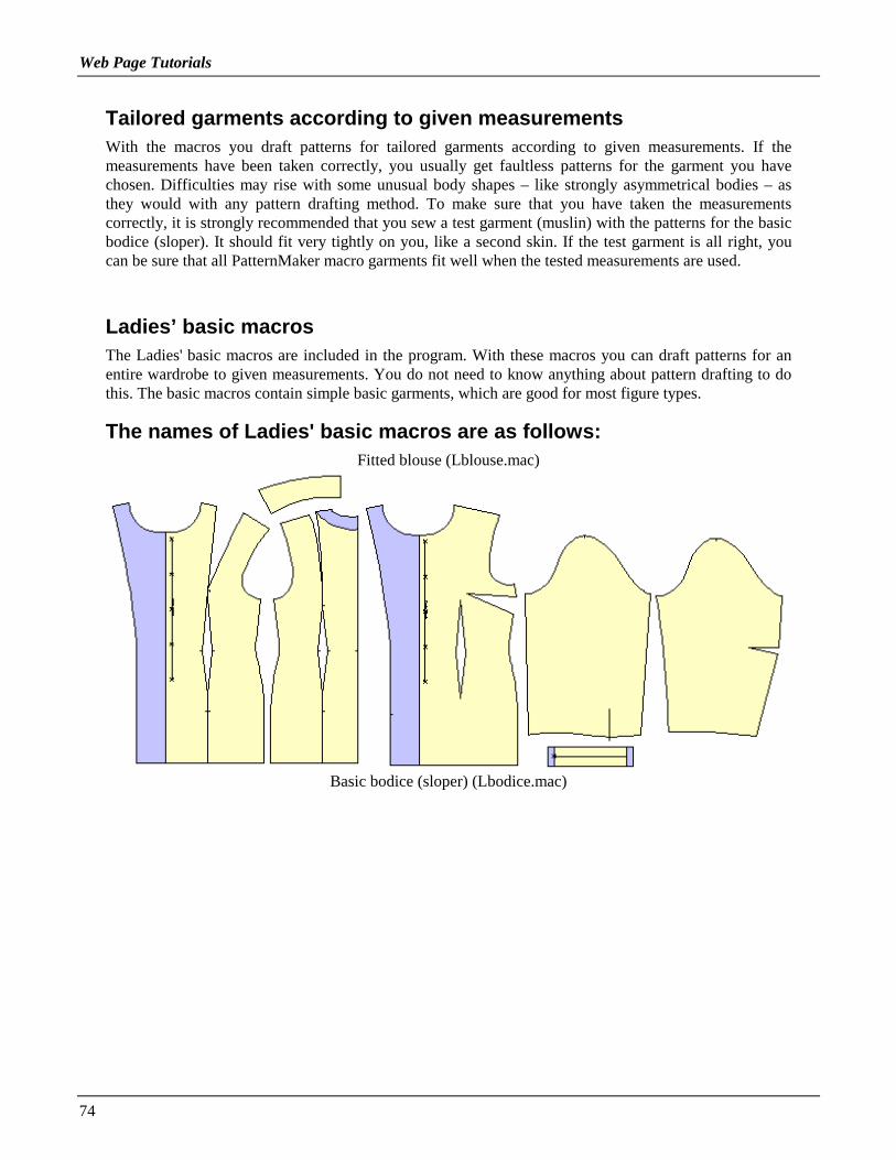
Web Page Tutorials
74
Tailored garments according to given measurementsWith the macros you draft patterns for tailored garments according to given measurements. If themeasurements have been taken correctly, you usually get faultless patterns for the garment you havechosen. Difficulties may rise with some unusual body shapes – like strongly asymmetrical bodies – asthey would with any pattern drafting method. To make sure that you have taken the measurementscorrectly, it is strongly recommended that you sew a test garment (muslin) with the patterns for the basicbodice (sloper). It should fit very tightly on you, like a second skin. If the test garment is all right, youcan be sure that all PatternMaker macro garments fit well when the tested measurements are used.
Ladies’ basic macrosThe Ladies' basic macros are included in the program. With these macros you can draft patterns for anentire wardrobe to given measurements. You do not need to know anything about pattern drafting to dothis. The basic macros contain simple basic garments, which are good for most figure types.
The names of Ladies' basic macros are as follows:Fitted blouse (Lblouse.mac)
Basic bodice (sloper) (Lbodice.mac)

Web Page Tutorials
75
Dress (Ldress.mac)
Jacket (Ljacket.mac)
Pants (Lpants.mac)

Web Page Tutorials
76
Pullover (Lpullov.mac)
Shirt (Lshirt.mac)
Skirt (Lskirt.mac)

Web Page Tutorials
77
Collars (Lcollars.mac)
This is how to run a macroTry the macros first with the default measurements given (= Scandinavian size 42) to get familiar withthe kinds of garments you can sew with the PatternMaker macros.
Choose the command File/Macro from the main menu. You can do this in three ways: either yousimultaneously press the <Alt> key and the underlined letter of the command (<Alt>F then M) or youpull down the File menu and then choose the command by clicking on it with the left button of the mouse(M1). Or you can click (M1) on the Macro icon on the left side of the screen. It’s the icon that says"mac."
When you get the dialog box depicted below, choose the macro you want to try by double clicking on itsname with the left mouse button (M1) or click on its name once and then click <OK>.

Web Page Tutorials
78
The program asks different things for different garments: single or double breasted, with or withoutsleeve, amount of ease etc. Choose the options by double clicking on the option or click on the optiononce and then click <OK>.
Note: You have to choose an option in each dialog box. If you click <OK> or type <Enter>without choosing any option, the macro stops.
Next, a dialog box for the measurements is opened. Instructions for taking the measurements are givenlater in this tutorial.
Move from field to field in the dialog box with <TAB> key, or by clicking the mouse (M1).

Web Page Tutorials
79
After having answered to all the questions and given the measurements, the program drafts all patternpieces for the selected garment on the screen. Wait until the hourglass cursor changes back to an arrow.If you cannot see the patterns at all or you see only part of them, type the <END> key on your keyboard.Then the screen is zoomed so that you can see the entire pattern.

Web Page Tutorials
80
Note: When you want to try another macro, clear the screen by choosing the command "File/New" fromthe main menu. Click the word "File" in the menu bar at the top of the screen with M1, and then the word"New" with M1. Usually, you will answer "No" when the program sakes whether you want to save thefile or not.
Adding seam allowancesIf you want to add seam allowances to the patterns, use the command Draw/Offset, from the Draw menu.After choosing the command, select all the pieces one by one with M1 and accept the selection with M2.
You can define the width of the seam allowance using the command Misc/Seam Width. Default width forthe seam allowance is 0,635 cm i.e. the width of the presser foot of the sewing machines.
Using the command Draw/Seam Allowance you can add a seam allowance of varying width to differentedges of the pattern. Please refer to the User’s manual to learn more about this.
Changing the pattern of the facings
Maybe you want that the facings can be distinguished from other pattern parts using different patternstyle in them. Use the command Edit/ Change/ Object. After choosing the command, select one or moreobjects (pattern pieces) whose pattern you want to change with M1, then accept the selection with M2 or<ESC>. Choose Pattern from the options given and after that the pattern style you want to use.
Note: Pattern styles other than empty use a lot of the printer ink, so it is worth while carefullyconsidering when to use other pattern styles. Your results will depend on the printer you use.
This is also the way to change the color of the patterns or the line styles.

Web Page Tutorials
81
Using the mouseThe left button of the mouse (in this tutorial = M1)
• when you draw, you indicate the points with the left button of the mouse
• when you edit the objects you select them with the left button of the mouse
• otherwise you use the left button of the mouse to select a command or to answer questions
• <ENTER> key can often be used in place of the left button of the mouse
With the right button of the mouse (in this tutorial = M2)
• you tell PatternMaker that you have made all the selections
• (often) interrupt the command
• in place of the right button of the mouse you can always use the <ESC> key
• Note: Never "click and drag" like you do in some other CAD programs. Just press the mousebutton down and release it before moving the mouse.
Taking the measurementsWhen you want to run a macro with your own measurements, do as follows:
Get acquainted with
• measuring instructions
• associated measuring illustration
Pay special attention when taking the measurements because the patterns the program drafts will not fitwell unless the measurements have been taken correctly. Write the measurements and the measuring datedown.
Note! Be careful when typing the measurements in the dialog boxes. Afterwards, PatternMakerdoes not let you recheck what measurements you have typed.
HINT: If you want to, you can save the dialog boxes through the Windows clipboard by using keycombination <Alt> + <PrintScreen>. From the Windows clipboard you can paste the dialogboxes into any Windows program (like Notebook, Notepad or Write). In most of the macros thereare two dialog boxes for measurements. You have to transfer the first one to the other programbefore you can move the other to the clipboard. Look for more information about the Windowsclipboard in your Windows’ user’s manual.
HINT: If you want to, you can make your own versions of the macros by opening the macro filein a text editing program and replacing the default measurements with your own measurements.

Web Page Tutorials
82
Default measurements are called "Test measurements" in the macro file.
The variables for the measurements are as follows: ry=bust circ., ky=neck circ., vy=waist circ.,yly=abdomen circ., aly=hip circ., rkkv=bust span, sl=back width, ylk=abdomen height, alk=hipheight, sp=back length, op=shoulder length, hp=sleeve length, kay=biceps circ., ray=wrist circ.,rk=bust height, vk=waist height.
Be sure to save the corrected macro in text form (.txt) and with a different name. Although theprogram can read the macro files with another extension than .mac, it is recommended that yousave them with this extension so that the program always prompts for them automatically.
PatternMaker screen
File nameIn the topmost bar of the screen, in brackets, is the name of the current file. The name is "noname.pat"until you save it with a name or open a saved file.
Menu barThe bar under the filename bar is the menu bar. You choose the commands from this menu or byclicking on an icon. Click with M1 on a word in the menu bar and you get a drop down menu where youcan choose the command with M1. You can choose a command also by typing a key combination<ALT> + the underlined letter of the command name.
Status bar
Drawing color
The first area in the status bar shows the drawing color of the objects (default color is white).
Web Page Tutorials
83
When you click the white box in the status bar with M1, you get a selection box with which youcan choose another drawing color. Changing the drawing color does not affect the objects thatalready have been drawn. It only affects the objects which are drawn after the change. If youwant to change the color of the objects that you already have drawn, use the commandEdit/Change.
Pattern style
The second area in the status bar is the pattern style of the objects. Click this with M1 to open abox where you can select another pattern, or fill, style. Just like the change of the drawing color,this change only affects the items which are drawn after the change.
Line type
The third area in the status bar is for the line type. You can choose from many line types.Change this the same way you change drawing color or fill style.
Layer
To the right of the line type there is a box for the layers. It tells the name of the current layer. Ifyou have not changed it, you can read "Layer 0" here. By clicking this box with M1 you canchange things concerning the layers. We will return to layers later on in this tutorial.
Mouse coordinates and units
The next area in the status bar tells the location of the mouse cursor on the screen, in X-Ycoordinates, and the measuring units (cm/inch). The units can be changed using the commandMisc./Units.
Commands
In the rightmost area of the status bar you see the latest command you have chosen or used. Ifthe command is in green, the command is still active and you cannot choose a new command. Ifthe command is in purple, you can click in the drawing area with the mouse and the command isrepeated. (Or you can choose a new command.)
Icon area (toolbar)On the left edge of the screen there is a vertical bar for the icons. The selection of icons changesdepending on the situation. We shall explain the function of the icons later on in this tutorial.
Drawing areaThe black part of the screen is the drawing area. Macros produce patterns in this area. When you areexecuting a drawing or editing command, you will usually click the mouse on items in the drawing area.
Command lineThe bottommost (blue) bar the screen is the command line. There you can read what the program isdoing and what it wants you to do next. Learn to look for instructions in this command line when youdon’t know what you should do.
LayersIn the black drawing area there are many layers superimposed one over another. You can use the layersto organize your pattern, for instance by placing the different sizes of the garment (36, 38, 40 …) ondifferent layers or different garments for one customer (skirt, jacket, blouse …) on different layers. You

Web Page Tutorials
84
can change the settings of the layers by clicking the layer box in the status bar (Layer 0) with M1. Youcan name the layers whatever you want: Click in the box for a layer’s name with M1 and write the newname on top of the old one.
One of the layers is active at a time. Drawing commands and the macros produce objects on the layerwhich is active. Activate a layer by clicking with M1 in its "Current" column.
The layers can be visible or hidden. To hide a layer, click with M1 in the "On" column to change it toOff. The printing command Print All prints the objects all the layers which are On. So, if you want toprint the items on one layer only, turn the other layers off.
HINT: When you make alterations to the fashion patterns or basic bodice (sloper) which youhave drawn using the macros, run the macro twice, first on layer 0 and then on layer 1. Thenhide layer 0. Make the alterations to the patterns on layer 1. From time to time you can displaylayer 0 and compare the changed patterns with the original ones. This is a good way to checkthat you have made all the changes you intended to do.
PatternMaker commands
General instructionsMost commands are run in the following way:
1. First you choose the command from the menu bar or by clicking upon an icon.
2. Then you select, with M1, all the objects which you want the command to affect.
3. After the selection(s) have been made, it/they are accepted with M2 or <ESC>. If you are executingthe erase command, it is performed now.
4. If you are executing one of the move or rotating commands, the following step is to give the base anddestination points of the move or the rotation.

Web Page Tutorials
85
Validity of a commandThe command which you have chosen is active until you choose another command. In the box at theright top corner of the screen you see which command you have chosen or used. If it is written in green,the execution of the command is unfinished and you cannot choose a new command yet. If the commandis written in purple and you click with the mouse on the screen, the command is repeated. At this pointyou also can choose a new command.
Please note this especially in situations, where you have used the erase command. If you don’t chooseanother command and click on the screen, you might erase something which you didn’t want to erase.Luckily there is the Edit/Undo command to undo the latest command.
If you want to choose a new command when the previous is still active (and written in green), press<ESC> key once or several times to cancel the current command.
Icons
Learn to use the icons. They speed up your work a lot. Please note that the choice of icons available

Web Page Tutorials
86
changes according to the situation. For instance, the Move icon is not available if there aren’t anyobjects in the drawing to be moved.
Other icons are described in the User’s manual.
DrawingWith the drawing tools of the program you can draw anything that you could draw with a pen and paper,compasses or ruler.
Exercise 1:Try to draw one of each of the objects described in the above picture. Use the Draw menu in the menubar or one of the drawing icons.
Objects and points
Objects (pieces)The pieces on the drawing area are called objects. There are 4 kinds of objects:
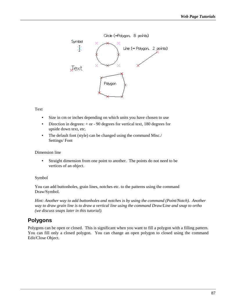
Web Page Tutorials
87
Text
• Size in cm or inches depending on which units you have chosen to use
• Direction in degrees: + or - 90 degrees for vertical text, 180 degrees forupside down text, etc.
• The default font (style) can be changed using the command Misc./Settings/ Font
Dimension line
• Straight dimension from one point to another. The points do not need to bevertices of an object.
Symbol
You can add buttonholes, grain lines, notches etc. to the patterns using the commandDraw/Symbol.
Hint: Another way to add buttonholes and notches is by using the command (Point/Notch). Anotherway to draw grain line is to draw a vertical line using the command Draw/Line and snap to ortho(we discuss snaps later in this tutorial).
PolygonsPolygons can be open or closed. This is significant when you want to fill a polygon with a filling pattern.You can fill only a closed polygon. You can change an open polygon to closed using the commandEdit/Close Object.

Web Page Tutorials
88
Points, vertices
Polygons are made of points. There are also 4 kinds of different points:
1. Line point is at the end of a straight line, or the end of an arc
2. A starting point of an arc
3. A corner point of an arc
4. An open point which marks the end of an open polygon
Note: You can display and hide the points using the function key <F5>.
The anatomy of an arcTo be able to use arcs in a controlled way as parts of the patterns, you need to know something about theanatomy of an arc.
The location of the corner point of an arc determines the shape of the arc.
Two rules• If the corner point, end point and the point after that form a straight line, the arc merges smoothly
into the next segment of the object, whether it is a line or an arc. A sleeve cap is an examplewhere there are many successive arcs and they must merge into each other nicely without kinks.
• If the corner point, end point and the point after that form an angle, the arc is merged into thefollowing segment of the object at that angle. This kind of corner is needed in neck openings andarmscyes of garment patterns.
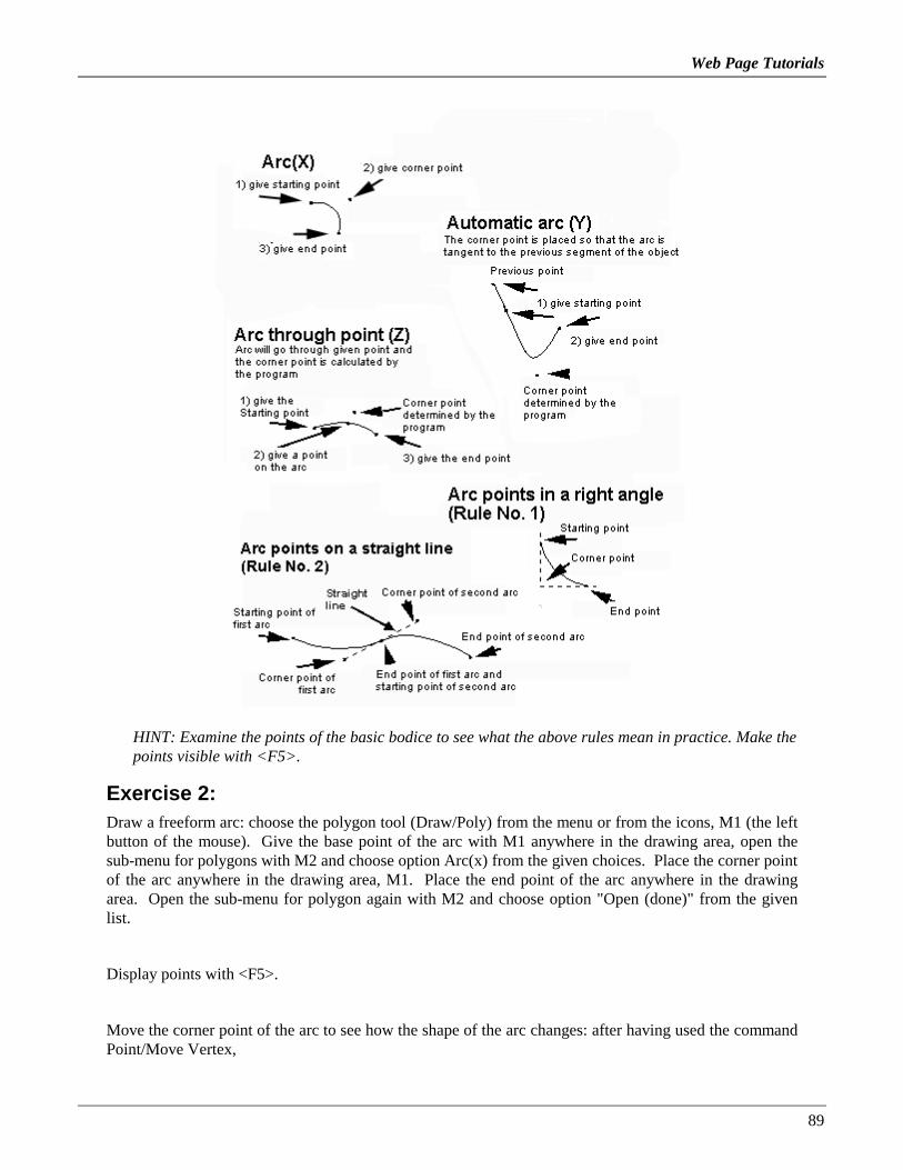
Web Page Tutorials
89
HINT: Examine the points of the basic bodice to see what the above rules mean in practice. Make thepoints visible with <F5>.
Exercise 2:Draw a freeform arc: choose the polygon tool (Draw/Poly) from the menu or from the icons, M1 (the leftbutton of the mouse). Give the base point of the arc with M1 anywhere in the drawing area, open thesub-menu for polygons with M2 and choose option Arc(x) from the given choices. Place the corner pointof the arc anywhere in the drawing area, M1. Place the end point of the arc anywhere in the drawingarea. Open the sub-menu for polygon again with M2 and choose option "Open (done)" from the givenlist.
Display points with <F5>.
Move the corner point of the arc to see how the shape of the arc changes: after having used the commandPoint/Move Vertex,

Web Page Tutorials
90
1. Select the corner point with M1, (it turns red)
2. And accept the selection with M2.
3. Give the base point of the move near the selected point, M1, and move the mouse. Notice how thepoint is moved when you move the mouse.
4. When you want to make the move, click with M1 at the end point of the move. We shall practice themove command more systematically later in this tutorial.
Giving a location for a pointWhen an object or point is moved or copied, the program asks for the base point and the destination pointof this action. These can be specified in two ways:
• either by clicking with M1 on the screen or
• typing the X and Y coordinates of the point from keyboard. Separate X and Y values with acomma (,). Start by typing the horizontal value (= X-value) of the point, then type a comma andthen type the vertical value of the point (=Y-value). If the X-value is negative it means to the leftof the origin and if it is positive it means to the right. If the Y-value is negative it means downand if it is positive it means up.
You can give the coordinates in four ways, of which we will discuss two here
Absolute address:• e.g. coordinate 1,2 means 1 cm to the right from the origin (0,0) and 2 cm to up from origin (0,0)
• and coordinate –1,-2 means 1 cm to the left from origin and 2 cm down

Web Page Tutorials
91
Relative address• @1,2 means 1 cm to the right from given point and 2 cm up from given point
Exercise 3:Draw a freeform line : after choosing the command Draw/Line, point the starting (base) point of the lineanywhere on the screen, M1. Move the mouse and point the endpoint (destination) anywhere on thescreen, M1.
Draw a horizontal line : (The command Draw/line is active and you do not need to choose it again.)Place the starting (base) point of the line anywhere on the screen, M1. Activate snap to ortho(horizontal/vertical snap) (<Ctrl F5>). Move the mouse and put the endpoint of the line anywhere in thedrawing area. Note that you can move the cursor only horizontally or vertically. (We’ll get back to thesnaps later on in this tutorial.) Deactivate snap to ortho (<Ctrl F1>).
Draw a horizontal line 10 cm long:
a) Choose the starting point of the line anywhere in the drawing area, M1. Type from the keyboard@10,0 and press <Enter>. The end point of the line is now 10 cm to the right and 0 cm up/downfrom the given starting point of the line.
b) Or type coordinates of both the starting and the end point from keyboard: After choosing thecommand Draw/Line, type from keyboard 0,0 and press <Enter>. Then type 10,0 and press<Enter>. The starting point of the line is now at the origin (0,0) of the drawing area and the endpoint 10 cm to the right from there.
Draw a 5 cm long vertical line which starts from the end point of the previous line typing its end pointfrom keyboard. Click M1 at the end point of the previous line. Use snap to endpoint, <Ctrl F3> to beexact. Type from keyboard @0,5 and press <Enter>.
Look carefully at the differences between the above exercises. If and when you make your own patternswith the program, it is vital that you understand the meaning of absolute and relative coordinates.
Selecting objects or pointsThere are many ways of selecting the objects and the points:
Selecting them one by oneClick on the objects/points, M1, M1, M1 …. until you have selected all the objects/points which youwant to; accept the selection with M2.
Selecting with a selection windowSelect one, M1, and click then selection window icon or type from keyboard "W". Choose the size and

Web Page Tutorials
92
the location of the selection window clicking on diagonal (opposite) corners of the desired selectionwindow: click at one corner, M1, move the mouse and click at the diagonal corner. Don’t click and drag,just click at the two corners of the desired selection window.
Selecting everything at onceSelect one, M1, and then click the selection-all icon or type from keyboard "A". Accept the selectionwith M2. If you want to select nearly all, first select all objects and then deselected the items which youdon’t want to select with M1.
Accepting the selectionAfter having selected all you want to select, accept the selection with M2 or pressing <Esc>.
DeselectingA selection of an object/point can be annulled by clicking on it again with M1.
Note that there are risks when using <Esc> key to annul the selection. For some commands, you cancancel the command with <Esc>, but for others, you can’t. If you were selecting for the commandsEdit/Erase or Point/Delete, pressing <Esc> completes the command and the items areerased/deleted. If you do this by mistake, use the command Edit/Undo to reverse the command.
With other commands you can use <Esc> to cancel the selection. You have to type it twice, sinceyou are completing the selection and then executing the command.
Selecting segmentsA segment is the section connecting two points of an object (a line or an arc). Some PatternMakercommands operate on segments rather than on points or objects. Select a segment by clicking with M1on it. Selecting is easier if there is no snap active (deactivate snap with <Ctrl F1> if necessary).
Using hot keysLearn to use the hot keys, as they will speed up your work:
• <F1> Zoom Out (makes everything appear smaller)
• <F2> Zoom In (makes everything appear bigger)
• <F3> Zoom To Mouse To examine a detail of your drawing, put the mouse on it and hit <F3> afew times.
• <F4> Grid On/Off Shows or hides the grid points.
• <F5> Points On/Off Shows or hides the vertices of all objects.
• <F6> Select Snap A menu will appear, listing all available snap modes.
• <F7> Arrows Shows or hides the grading arrows. This function toggles between three options:no arrows, arrows only, and arrows and their names.
• <F8> Absolute Mode/Mouse Mode Switches digitizer mouse modes. This only applies if youare using a digitizer.

Web Page Tutorials
93
• <F9> Pan to Mouse The view is moved to place the current mouse location at the center of thedrawing area.
For the following, hold down the <Ctrl> key while typing the given Function key
• <Ctrl>+<F1> Snap off
• <Ctrl>+<F2> Snap to grid. Also shows the grid.
• <Ctrl>+<F3> Snap to end point
• <Ctrl>+<F4> Snap to nearest
• <Ctrl>+<F5> Snap to ortho
• <Ctrl>+<F6> Snap to mid point
• <Ctrl>+<F7> Snap to intersection
• <Ctrl>+<F8> Snap to offset
• <Ctrl>+<F9> Snap to distance from end point
Other hot keys
• <Pg Up> Zoom out
• <Pg Down> Zoom in
• <Home> Zoom in on mouse (same as <F3>
• <End> Zoom All. Shows all objects.
• <Arrow keys> Pan left, right, up, down
SnapSnap functions are very helpful when using the editing commands. Often – when you have to be exact -they is necessary. It is worth while getting acquainted with them and learning to use them.
Snap functions set limits to the movements of the mouse and taking seize of a point:
• <Ctrl F1> Snap Off There are no snap points
• <Ctrl F2> Snap to Grid The nearest grid point
• <Ctrl F3> Snap to End Point The nearest vertex of an object
• <Ctrl F4> Snap to Nearest The nearest point on an object, whether or not it’s a vertex
• <Ctrl F5> Snap to Ortho The nearest point on a horizontal or vertical line from the last pointyou entered

Web Page Tutorials
94
• <Ctrl F6> Snap to Midpoint The nearest midpoint between two vertices of an object
• <Ctrl F7> Snap to Intersect The nearest intersection of two lines or objects
• <Ctrl F8> Snap to Offset A point offset from two lines of an object. When you select Snap tooffset, you will be asked for two distances; these will be the offsets from the two lines. This isfor making seam allowances and facings from existing pattern pieces.
• <Ctrl F9> Snap to Measured Distance A point a specified distance from an existing vertex.The distance is measured along the edge of the object, rather than in a straight line. Use thismode to place a point a certain distance from the end of a curved line.
HINT: Snap functions require lots of computations, so they will use a lot of your computer’s processingpower, especially snap to intersection <Crtl F7>. Snaps <Crl F6>, <Crtl F8> and <Crtl F9> will slowyour computer when they are activated unnecessarily. Don’t keep them activated if not necessary. Snapto endpoint (<Crtl F3>) is often useful and there usually is no harm in keeping it active while working.
Saving a fileIt is important to save the file that you are working with, every now and then. Then it won’t be acatastrophe, if you make an error, which you cannot annul with the command Edit/ Undo. Pleaseremember, that you can annul only the latest execution of a command.
Save the file by choosing the command File/ Save As from the menu and give the file a name of yourchoice. The PatternMaker file extension .PAT is automatically added, so you don’t have to type it. Inthe dialog box for saving you can also choose the directory where you want to save the file. Later on –after giving the file a name – you can save it with the command File/ Save. Please notice that there alsoare icons for saving and opening a file.

Web Page Tutorials
95
ELEMENTARY TUTORIAL #2
Lesson 2Note: In this tutorial an abbreviation of M1 is used for the left button of the mouse and an abbreviationof M2 for the right button of the mouse
Other abbreviations:
CF = center front
CB = center back
2nd lesson• Moving objects and points
• Grouping objects
• Copying objects
• Rotating objects and points
• Cutting and joining objects
• Mirroring objects
• Aligning point
• More design exercises
• The menu bar
• Printing
Moving objects
Moving objects is done using the command Edit/Move and moving points by the commandPoint/Move Vertex. Choose the command first and then proceed as illustrated in the picture below:
Exercise 4:

Web Page Tutorials
96
1. Clear the screen using the command File/New. Answer "No" when the program asks whether youwant to save the file or not.
2. Run the macro Lbodice.mac. Move one of the pattern pieces (it doesn’t matter where) as follows:
3. Choose the command Edit/Move
4. Select the pattern piece (object) you want to move with M1
5. Accept the selection, M2
6. Choose the starting (base) point of the move, preferably inside the piece, M1
7. Move the mouse and select the end (destination) point of the move at the place where you wantto move the piece to, M1
Exercise 5 : Undo the move with the command Edit/Undo. Now move the side panel of the front pattern2 cm to the right from the CF piece:
1. The move command is now ready to repeat and you do not need to choose it again (look at thecommand box at the top right corner of the screen to see that the command appears in purple).

Web Page Tutorials
97
2. Select the front side piece, M1
3. Accept the selection, M2
4. Type from keyboard 0,0 <Enter> for the starting (base) point of the move
5. Type from keyboard 2,0 <Enter> for the destination point of the move
Exercise 6 : Now move the back piece so that it touches front side piece at the hem:
1. The move command is now ready to repeat and you do not need to choose it again
2. Select the back piece and its waist dart piece for moving, M1, M1
3. Accept the selection, M2
4. Choose the point where the side seam of the back piece meets the hem as the base point of themove (Use snap to end point to be exact, <Ctrl F3>), M1
5. Choose the point where the side seam of the front side piece meets the hem as the destinationpoint of the move, M1
Grouping objects
PatternMaker objects can be grouped together. When objects are grouped, you can apply a commandto several objects at one time. The most common reason for grouping is the need to move severalobjects at the same time.
Exercise 7 : Continue with the pattern you made in the previous exercise. Create a group containing theback piece and its waist dart piece and move the group.
1. Choose the command Symbol/Group
2. Select back piece, M1, and its waist dart, M1
3. Accept the selection, M2
4. Accept the grouping in the dialog box, M1. In this dialog box you can also give the group aname, if you want to.
5. Try moving this group. You’ll notice that you can select the whole group by clicking on anyobject once with M1.
Copying objects
Copying the objects is done with the command Edit/Copy or using the copy icon.
Exercise 8 : Continue from the result of the previous exercise. First copy the back piece:
1. Choose the command Edit/Copy
2. Select the back piece for copying, M1 (remember that it is now a group, so that you can selectboth the back piece and its waist dart at the same time)
3. Accept the selection, M2
4. Choose the base point of the copy inside the selected piece, M1
5. Move the mouse and point the destination point of the copy on the location where you want toput the new piece, M1
Exercise 9 : Continue the exercise and copy the center front piece 30 cm to the left from the originalcenter front piece:
1. The copy command will now repeat, so you don’t need to choose it again

Web Page Tutorials
98
2. Select center front piece, M1
3. Accept the selection, M2
4. Type from keyboard 0,0 <Enter> as the base point of the copy
5. Type from keyboard -30,0 <Enter> as the destination point of the copy
6. Zoom the drawing so that you can see the whole picture by pressing the <End> key on thekeyboard.
Rotating objects and points
Rotating objects is done with the command Edit/ Rotate and rotating points with the command Point/Rotate vertex. After choosing the command, select the object(s) or point(s) which you want to rotate,M1. Accept the selection with M2. Then give the point about which the rotation is to be done (thecenter point of the rotation), M1.
The amount of rotation can be given in three different ways :
1. Select two points on the screen with M1 (base point and destination point), and the rotationamount is the distance between these two points
2. Select one point on the screen with M1 (base point) with M1 and type the rotation distance fromthe keyboard. The program calculates how many degrees of rotation will move the point thisdistance. If you want to rotate clockwise, give a negative (-) distance and if you want the rotationto be counterclockwise, give a positive (+) distance.
3. Type the rotation angle, in degrees, from keyboard. If you want to rotate clockwise, give anegative (-) angle and if you want the rotation to be counterclockwise, give a positive (+) angle.
If you type 180 as the rotation angle, the object is rotated upside down. If you type 90, the object isrotated 90° counterclockwise. If you type –90, the object is rotated 90° clockwise.
Exercise 10: Practice these three ways of rotating an object.
1. Clear the window with the command File/ New.
2. Draw a line: Choose the command Draw/ Line, then select the end points of the line in thedrawing area, M1 and M1.
3. Choose the command Edit/ Rotate.
4. Rotate the line by selecting the center point, base point and destination point of the rotation withmouse (use snap to end point <Ctrl F3> to be exact)
5. Select the line, M1, and accept the selection, M2.
6. Choose one end of the line as the center point of the rotation, M1.
7. Choose the other end of the line as the base point of the rotation, M1.
8. Move the mouse and choose the destination of the rotation, M1.
Rotate the line, selecting the center point and the base point of the rotation with the mouse and typingthe distance from the keyboard
1. Select the line, M1, accept the selection, M2.
2. Choose one end of the line as the center point of the rotation (use Snap to End Point <Ctrl F3> tobe exact), M1.
3. Choose the other end of the line as the base point of the rotation, M1.
4. Type from keyboard 5 <Enter> (rotating distance is then 5 cm).

Web Page Tutorials
99
Rotate the line, selecting the center point of the rotation with mouse and typing the rotation anglefrom keyboard
1. Select the line, M1, accept the selection, M2.
2. Choose one end of the line as the center point of the rotation (use snap to end point <Ctrl F3> tobe exact), M1.
3. Type from keyboard: 30 <Enter> (rotation angle is then 30o).
EXERCISE 11 : Exercise in rotating points:
Clear the screen using command File/New. Answer "No" when the program asks whether you wantto save the file or not. Draw a rectangle: Choose the command Draw/Rectangle and then enter twoopposite corners of the rectangle, M1, M1.
Rotate the left side of the rectangle 5 cm to the left (= counterclockwise): Choose the commandPoint/Rotate vertex.
1. Select the top point of the left side of the rectangle, M1,
2. Accept the selection, M2.
3. Choose the center point of the rotation on the bottom point of the left side of the rectangle, M1(use snap to end point <Ctrl F3> to be exact).
4. Choose with mouse the base point of the rotation on the top point of the left edge of the rectangleand
5. Type from keyboard 5 <Enter>
Rotate the right side of the rectangle 3 cm to the right (= clockwise)
1. Select the top point of the right side of the rectangle, M1,
2. Accept the selection, M2.
3. Choose the center point of the rotation on the bottom point of the right side of the rectangle, M1(use snap to end point <Ctrl F3> to be exact).
4. Choose the base point of the rotation on the top point of the right edge of the rectangle and
5. Type from keyboard –3 <Enter>
Memorize this rule for rotating objects and points
Click the mouse as follows
M1 (selection of the objects/points to be rotated), M2 (accepting the selection), M1 (center point),M1 (base point), M1 (destination point) i.e.
M1, M2, M1, M1, M1 orM1, M2, M1, M1, distance <Enter> orM1, M2, M1, angle <Enter>
EXERCISE 12 : In this exercise you will rotate an object in a real designing situation: closing the bustdart of the front piece and moving it to the hem.
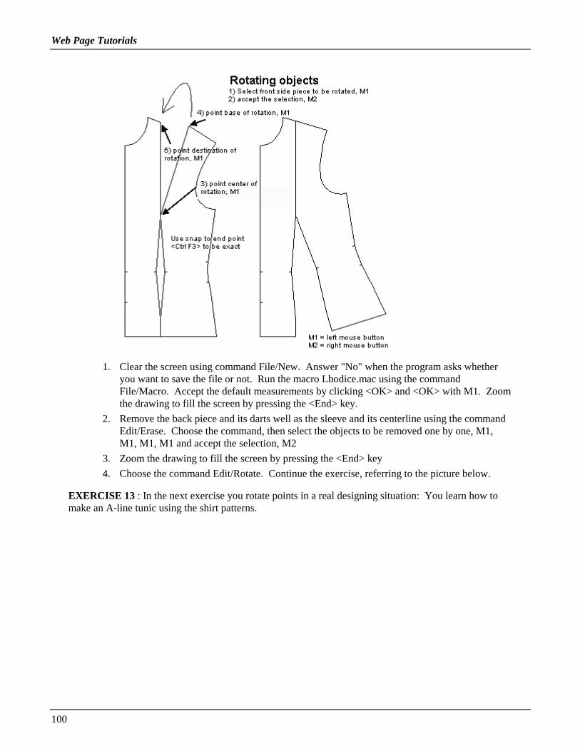
Web Page Tutorials
100
1. Clear the screen using command File/New. Answer "No" when the program asks whetheryou want to save the file or not. Run the macro Lbodice.mac using the commandFile/Macro. Accept the default measurements by clicking <OK> and <OK> with M1. Zoomthe drawing to fill the screen by pressing the <End> key.
2. Remove the back piece and its darts well as the sleeve and its centerline using the commandEdit/Erase. Choose the command, then select the objects to be removed one by one, M1,M1, M1, M1 and accept the selection, M2
3. Zoom the drawing to fill the screen by pressing the <End> key
4. Choose the command Edit/Rotate. Continue the exercise, referring to the picture below.
EXERCISE 13 : In the next exercise you rotate points in a real designing situation: You learn how tomake an A-line tunic using the shirt patterns.

Web Page Tutorials
101
1 Clear the screen using the command File/New. Answer "No" when the program askswhether you want to save the file or not.
2 Run the macro Lshirt.mac using the command File/Macro. Accept the default measurementsoffered by clicking <OK> and <OK> with M1. Zoom the drawing to fill the screen bypressing the <End> key.
3 Erase the sleeve and its centerline as well as the collar and the cuff pieces using thecommand Edit/Erase. Select the objects to be erased one by one, M1, M1…. And accept theselection, M2.
4 Zoom the drawing to fill the screen by pressing the <End> key. 5 Choose the commandPoint/Rotate vertex. Continue the exercise according to the picture below.
Cutting and joining objects
EXERCISE 14 : In this exercise you learn how to cut objects.

Web Page Tutorials
102
1 Clear the screen using the command File/New. Answer "No" when the program asks whetheryou want to save the file or not.
2 Draw a rectangle using the command Draw/Rectangle. Choose on the screen two oppositecorners of the rectangle, M1, M1.
3 Draw a line that cuts across the rectangle: use the command Draw/line, and choose the end pointsof the line with the mouse, M1 and M1.
4 Continue the exercise according to the picture: cut the rectangle with the line and move thepieces apart from each other.
EXERCISE 15 : Now an exercise to join pieces.
1 Continue from where you left off in the previous exercise.
2 Join the pieces of the rectangle, which you moved apart. First move the pieces so that they areagain side by side. Choose the command Edit/Move. Select the right hand piece, M1 and acceptthe selection, M2.
3 Activate snap to end point, <Ctrl F3>.
4 Choose as the base point of the move the bottom left corner of the right hand piece which youjust selected for the move, M1.
5 and choose as the destination point of the move the bottom right corner of the other piece, M1.
6 Then join the pieces. Choose the command Edit/Join. Select one of the pieces, M1 and acceptthe selection, M2.
7 Choose the other piece, M1, and accept the selection, M2; the pieces are joined.
Hint: Look at the blue command bar at the bottom of the screen. You should see the words:"calculating … done". Sometimes it may happen that the program cannot join pieces that justbarely meet at the edges. In such a situation, delete one or more segments that overlap eitherfrom one of the pieces or both (Point/Delete Segment). Select the segment you want to delete,M1, accept, M2. Then run the Join command again. Note that there are always two overlappingsegments, one from each object, in such a case.

Web Page Tutorials
103
Mirroring objects
EXERCISE 16 : Next you are going to try mirroring objects in a real designing situation. You are goingto draw a facing for a front piece.
1 Clear the screen using the command File/New. Answer "No" when the program asks whetheryou want to save the file or not.
2 Run the macro Lbodice.mac using the command File/Macro. Accept the default measurementsoffered by clicking <OK> and <OK> with M1. Zoom the drawing to fill the screen by pressingthe <End> key.
3 Erase the back piece and its waist dart as well as the sleeve and its center line with the commandEdit/Erase. Select the pieces to be erased one by one, M1, M1, M1, M1 and accept the selection,M2.
4 Zoom the drawing to fill the screen by pressing the <End> key. Choose the commandEdit/Mirror. Select the CF piece as the piece to be mirrored, M1, and accept the selection, M2.
5 Choose one end of the mirror line at the CF point of the neck opening, M1, and the other end atthe CF point of the hip, M1 (use snap to end point <Ctrl F3> to be exact).
6 Move the mirrored facing piece 4 cm to the left to form a button extension: choose the commandEdit/Move, select the facing piece, M1, and accept the selection, M2;
7 Type as the base point of the move, from keyboard, "0,0" <Enter> and as destination point "-4,0"<Enter>.
8 Move the center front points of the center front piece 2 cm to the left: choose the commandPoint/Move Vertex; select all points on the CF line M1, M1, M1, M1, M1. Accept the selection,M2. Type, from keyboard, the base point of the move as "0,0" <Enter> and the destination of themove as "-2,0" <Enter>.
9 Move corresponding points on the CF line of the facing 2 cm to the right. The commandPoint/Move Vertex will repeat, so you don’t need to choose it again. Select the CF points of thefacing M1, M1, M1, M1, M1 and accept the selection, M2; choose as the base point of the movethe CF hem point of the facing, M1, and as the destination point of the move the CF hem point ofthe CF piece, M1
10 Join the CF piece and the facing: choose the command Edit/Join, select the CF piece with M1,accept with M2; select the facing with M1, and accept with M2.
Aligning points
Exercise 17 : Next you will learn to align points horizontally and vertically. Do the following exerciseaccording to the picture below.

Web Page Tutorials
104
In this exercise you straighten the CB seam of a ladies’ jacket and shorten the jacket to extend to thetop of the hip (abdomen).
1 Run the macro Ljacket.mac (File/Macro) with the default measurements. Remove all sleeve,pocket and facing pieces using the command Edit/Erase. Select all the pieces you are going toerase one by one, M1, M1, M1…, accept, M2.
2 Display points by pressing <F5>.
3 Align the CB points with the back neck CB point: Choose the command Point/Align X. Selectthe CB point of the back neck, M1, accept, M2
4 Select the CB points on waist, abdomen, hip and hem, M1, M1, M1, M1, accept, M2
Then align all the hem points according to any top hip (abdomen) point:
1 Choose the command Point/Align Y
2 Choose any point at the top of the hip (e.g. at the CB seam), M1, accept, M2
3 Select all hem points of all pieces, M1, M1, M1 …, accept the selection M2
HINT: Aligning points is a handy way to remove seam allowances from CF or CB seam. Firstdraw seam allowance pieces around all pieces (Draw/Offset). Align the CB points of the seamallowance pieces with any CB points of the CB piece and CF points of the front seam allowancepiece with any CF point of the CF piece.
Note: The same result is better received by removing all hip and hem points (Point/Deletevertex). The feature Align Y is here used for pedagogic reasons. Using Align Y in the waydescribed above causes two points to be one on the other at the hem points which may causeproblems when creating seam allowances.
More designing exercises
Exercise 18 : In the following exercise you learn the easiest way to alter a jacket with a tailored collarinto a jacket with a shawl collar. Look at the picture below

Web Page Tutorials
105
1 Clear the screen using the command File/New. Answer "No" when the program asks whetheryou want to save the file or not. Run the macro Ljacket.mac (File Macro).
2 Erase all other pieces except the CF piece and the collar. Choose the command Edit/ Erase.Select all the pieces to be erased one by one, M1, M1, M1…, accept, M2.
3 Erase all other pieces except the CF piece and the collar. Choose the command Edit/ Erase.Select all the pieces to be erased one by one, M1, M1, M1…, accept, M2.
4 Move the collar so that it touches the CF piece (as in picture): Choose the command Edit/ Move.Select the collar, M1, accept, M2. Choose as the base point of the move the collar point which ismarked with an arrow in the picture, M1, and as the destination point of the move the point of CFpiece which is marked with an arrow in the picture, M1. Use snap to end point to be exact (<CtrlF3>).
5 Join the collar to the CF piece: after choosing the command Edit/ Join, select the collar, M1,accept, M2 and select the CF piece, M1, accept, M2.
6 If you want to, you can remove the angle in the shawl collar by deleting the points in it. Choosethe command Point/Delete vertex. Select the points to be removed, M1, accept, M2.
HINT: Even if the outer edge of the shawl collar can be seen without joining the pieces, it isusually wise to join the pieces. This way, it is much easier to draw seam allowances around thepieces.
Exercise 19 : The next exercise teaches you the easiest way to alter a normal jacket into an A-line jacket.Look at the picture below.

Web Page Tutorials
106
1 Clear the screen using the command File/ New. Answer "No" when the program asks whetheryou want to save the file or not. Run the macro Ljacket.mac (File/ Macro).
2 Move the front and the back pieces so that they touch at the hem (Edit/ Move). The base anddestination points of the move have been marked in the picture.
3 Rotate the shoulder/bust dart of the front piece until it is closed (Edit/ Rotate). The center, baseand destination points of the rotation have been marked in the picture. Use the snap to end point<Ctrl F3> to be exact. Rotate the back shoulder dart in the same way to close it.
4 Join the front and the back pieces so that you get a single front and back piece. Choose thecommand Edit/ Join. Select one of the pieces to be joined, M1, accept, M2. Select the otherpiece to be joined, M1, accept, M2.
Look at the blue command line at the bottom of the screen. You should see: "calculating …done". Sometimes it may happen that the program cannot join pieces whose edges just touch. Insuch a situation, delete one or more of the overlapping segments from one of the pieces or both.(Point/ Delete Segment). Select the segment you want to delete, M1, accept, M2. Note that thereshould be two segments together, one from each object.
5 Delete the points of the "hem dart" which appeared when you joined the pieces (Point/Delete

Web Page Tutorials
107
Vertex). Select the points to be deleted one by one, M1, M1, M1 …, accept the selection, M2
6 After you have deleted the points, if the piece has an open section at the hem, close it using thecommand Edit/Close Obj. Select the piece to be closed, M1 and accept the selection, M2.
Exercise 20 : This exercise teaches you to add ease to patterns.
Note: PatternMaker macros produce patterns which are ready to sew. You don’t have to add ease tothem. If you want to sew a T-shirt or a sweater with the shirt patterns, or an overcoat with the jacketpatterns, then you may want to add ease to the patterns.
1 Clear the screen using the command File/New. Answer "No" when the program asks whether youwant to save the file or not. Run the macro Lbodice.mac (File/ Macro).
2 Erase all other pieces but the front and the back pieces and the back waist dart. Choose thecommand Edit/ Erase. Select the pieces to be erased one by one, M1, M1, M1…, accept, M2.
3 Move the points of the front and the back piece. Select the points with the help of a selectionwindow as in the picture: Choose the command Point/Move Vertex. Type from keyboard "W" orclick the window icon in the icon area with M1. Choose one corner of the selection window, M1,move the mouse and choose the opposite corner of the selection window, M1. Accept selectionwith M2. The base and the destination points of the move have been marked in the picture below.
Exercise 21 : It is worthwhile knowing how to move a dart to another place. Do the following exercise.

Web Page Tutorials
108
1 Continue from where you left off in the previous exercise.
2 Move the front pieces to that they touch at hem. Choose the command Edit/Move. Select thepiece to be moved, M1, accept, M2. Choose the base and destination points marked in the picturebelow, M1, M1. Use snap to end point to be exact <Ctrl F3>.
3 Rotate the front shoulder/bust dart until closed. After choosing the command Edit/Rotate and thepiece to be rotated (M1, M2) choose the center, base and destination points of the rotation asmarked in the picture below, M1, M1, M1.
4 Draw a line from the bust point (apex) across the front side seam. After choosing the commandDraw/Line, Use M1 to enter the end points of the line. The line must begin exactly at the bustpoint and therefore you should use snap to end point <Ctrl F3>.
5 Cut the front side piece with the line you drew (Edit/Cut). After choosing the command, selectthe side piece, M1 and accept, M2. Then select the cutting line, M1, M2. Look at the bluecommand line at the bottom of the screen to see that the cut was made successfully. You shouldsee the words "Calculating … Done".
6 Erase the cutting line (Edit/Erase). Choose the command, then select the line, M1 and accept theselection, M2.
7 Rotate the bottom part of the side piece so that the shoulder/bust dart is closed. Choose thecommand Edit/Rotate and the piece to be rotated (M1, M2) point the center, base and destinationpoints, M1, M1, M1.
8 Rotate the bottom part of the side piece so that the shoulder/bust dart is closed. Choose thecommand Edit/Rotate and the piece to be rotated (M1, M2) point the center, base and destinationpoints, M1, M1, M1.
NOTE! When using the cutting the command (Edit/Cut), you always have to select the piece to be cut

Web Page Tutorials
109
first, and the piece to cut with second.
Exercise 22: Learn to rotate points by drawing patterns for an A-line dress.
1 Clear the screen using the command File/New. Answer "No" when the program asks whether youwant to save the file or not. Run the macro Ldress.mac (File/Macro). Erase the sleeve and itscenterline as well as all facings. After choosing the command Edit/Erase, select the objects to beerased one by one M1, M1. M1 … accept selection, M2.
2 Choose the command Point/Rotate Vertex. Select the points of the CF piece to be rotated, M1,M1, M1 (look at the caption "These points have been rotated" in the picture below). Then selectthe center point of the rotations at the waist point of the piece, M1 (refer to the picture). Choosethe hem point as the base point of the rotation, M1. Type as the distance or end point of therotation, from keyboard, "2" and press <Enter>.
3 Continue as in the picture and rotate the corresponding points of other pattern pieces. Please notethat the points of the CF and CB lines are not rotated.
NOTE! When you rotate the points of both sides of a pattern piece, the hem rises to the level wherethe hem points will be after the rotation. Therefore it is necessary – at least when the amount of therotation is large – to add a new point to hem between the hem points which are to be rotated. Thisnew point remains on the correct hemline after the rotation. To be able to curve the hem, you alsoneed to add additional new points between the original hem points and the point you just added.Look at the picture below.
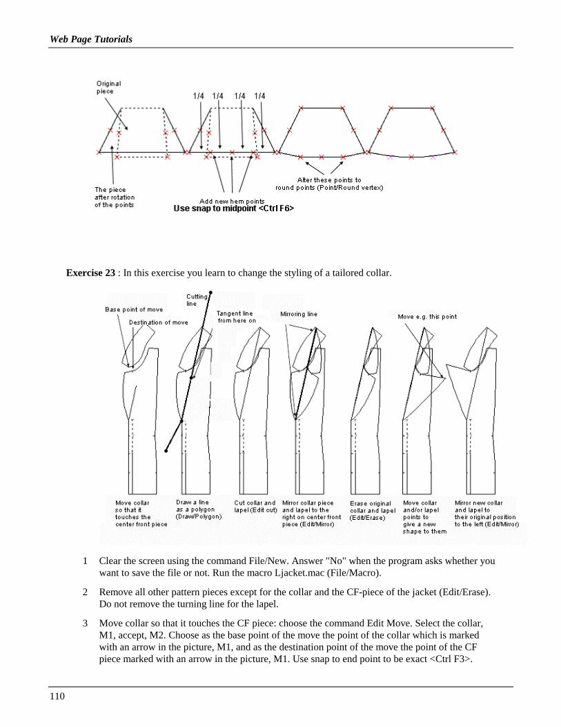
Web Page Tutorials
110
Exercise 23 : In this exercise you learn to change the styling of a tailored collar.
1 Clear the screen using the command File/New. Answer "No" when the program asks whether youwant to save the file or not. Run the macro Ljacket.mac (File/Macro).
2 Remove all other pattern pieces except for the collar and the CF-piece of the jacket (Edit/Erase).Do not remove the turning line for the lapel.
3 Move collar so that it touches the CF piece: choose the command Edit Move. Select the collar,M1, accept, M2. Choose as the base point of the move the point of the collar which is markedwith an arrow in the picture, M1, and as the destination point of the move the point of the CFpiece marked with an arrow in the picture, M1. Use snap to end point to be exact <Ctrl F3>.

Web Page Tutorials
111
4 Draw a cutting line, which starts from outside of the CF piece, goes along the turning line of thelapel, and continues from there as a tangent line across the collar. Because this line has more thantwo points, you cannot use the Line drawing tool. Use the Draw/ Polygon tool. Choose the firstpoint of the polygon somewhere outside the CF piece (look at the picture), M1. Choose thefollowing points of the line (polygon) at the bottom edge of the turning line for the lapel, M1,and at the top edge of the turning line for the lapel, M1. Open the drop-down menu for thepolygon with M2 and choose from it "Tangent Line" (= a line which continues in the samedirection as the previous segment of the polygon), M1. Finally, place the last point of the cuttingline outside the collar, M1. Pan the view using the arrow keys in keyboard, if you need to.
5 Cut the collar and the CF piece with the line you just drew. Use the command Edit/Cut. Selectthe collar, M1 and accept it, M2. Select the cutting line, M1, accept, M2. (It is easiest to select aline near its end point. Select the CF piece, M1, accept, M2. Select the cutting line, M1, accept,M2.
Look at the blue command line at the bottom of the screen to see that the cut really has takenplace (you should see "Calculating … done").
6 Remove the cutting line. Use the command Edit/Erase. Select the line, M1, and accept theselection, M2.
7 Mirror the small pieces of the collar and the lapel you just cut, on top of the front piece. Use thecommand Edit/Mirror. Select the collar, M1, and the lapel piece, M1. Accept the selection, M2.Point the bottom end of the line across which the mirroring is to be done (= bottom end of theturning line of the lapel, M1 (look at the picture). Point the top end of the mirroring line (= thepoint where the cutting line crossed the collar, M1 (look at the picture).
8 Remove the original cut pieces of the collar and the lapel (Edit/Erase).
9 Alter the collar and/or the lapel to the shape you want by moving its point(s). Use the commandPoint/Move vertex. Select the points to be moved, M1, M1 …, accept the selection, M2. Choosethe base point of the move (preferably near the points to be moved), M1. Move the mouse andchoose the destination of the move anywhere you want it to be, M1. If you are not pleased withthe result, undo the move with the command Edit/Undo and try again.
10 When you are satisfied with the new shape of the collar and the lapel, mirror them back to theiroriginal position to the left side of the turning line of the lapel. Use the command Edit/Mirror.Select the collar piece, M1 and the lapel, M1, accept the selection, M2. Choose the line acrosswhich the mirroring is to be done. It is the same line as the previous mirroring line, M1, M1.
11 Remove the collar piece and the lapel on the CF piece (Edit/Erase).
12 If you want to, you can join the collar pieces to each other, and join the lapel to the CF piece(Edit/Join). This is not necessary, but if you want to draw seam allowances around the pieces, itis easier when the pieces are joined.
The menu bar
You have already used many of the PatternMaker commands doing the exercises above. Now it is timelook at the menu bar more systematically. Try the commands one by one and see what happens. If youneed any more information of them, please refer to the owner’s manual.
FILE
New Clear screen and start a new drawing.

Web Page Tutorials
112
Open Clear screen and open a drawing file.Save Save current drawing in a file.Save As ... Save current drawing in a file with a different name.Set Print Area Set current print area i.e. the area of one page of your printer.Print Print current print area i.e. one page.Print All Print entire drawing.Macro Run a macro.Exit Quit PatternMaker program.
DRAW
Line A line is a polygon with two vertices. Input the two end points.Rect A rectangle is a closed polygon with four vertices. To draw a rectangle, input two oppositecorners. PatternMaker will add the other two corners.Poly Select the Poly command and then start entering points. This will draw a series of lines. Todraw curves instead of straight lines, choose an option from the point types menu, M2. When you aredone, choose one of the Done (closed or open) options from the point types menu. The options youchoose from the options menu (M2) are:
Line (the default). This draws straight lines.Arc. This begins an xarc. The next point you input will be the corner point, and the point afterthat will be the end point of the xarc.Arc through point . This also begins an xarc. The difference is that the next point you select isnot the corner point. Instead, PatternMaker calculates the corner point so that the arc will gothrough the point you selected.Automatic arc . This draws an xarc, but you don’t need to input a corner point. Instead, youinput the end point and PatternMaker places the corner point. It does this such that the arc istangent to the previous segment of the object.Tangent . This draws a line, but it forces this line to continue in the direction established by theprevious segment. After you draw this segment, the option reverts to Line.Undo last point . This removes the last point you drew, then lets you continue from there.Done (Closed) . This finishes drawing the object and makes it a closed polygon.Open (done) . This finishes drawing the object and makes it an open polygon.Cancel . This cancels the command and gets rid of the partially drawn object.
Text When you run this command, you will first input the point where the text goes. Then a dialogbox will appear for you to enter the actual text, the angle and the size. To set the font, refer to theChange Font and Set Font functions.
Dot A dot is a polygon with one vertex. It is displayed as a tiny circle. Caution: Not all printers printdots the same way they appear on the screen. Make sure your printer can print dots before you usevery many of them in your patterns.
Circle A circle is really a polygon, with four curved sections and eight points. You draw a circle byentering the center point and the radius. Once it’s drawn, a circle is just like any other polygon.
Dim A dimension line is a measured distance between two points. The program will prompt you for"First Point" and "Second Point". These are the start and end of the distance to be dimensioned. Clickon two points on the screen. The program will connect them with a line and two arrows. It will askyou for the "Location for label:". Click another point and you will get a dimension line.
Seam Allowance If you want to have a seam allowance that is offset by different seam widths atdifferent points on your pattern, you can select a partial section of an object; enter a seam width, and

Web Page Tutorials
113
then continue selecting more sections and giving them different seam widths. The dialog box thatasks you for the seam width gives you choices of "OK" to continue, or "Open" or "Closed" to stopdrawing the seam allowance.
After you finish drawing the seam allowance, PatternMaker asks you if you want to group it with theoriginal object (see Group command).
Note: The Seam Allowance command may not work well for objects that contain sharp angles orinward bends, or that overlap or cross over themselves. Most normal pattern pieces will not havethis problem unless they contain darts. One way to avoid this problem is to draw the dart as aseparate object from the main pattern piece.
Offset This is similar to the Seam Allowance command and creates a polygon object that is offset agiven (constant) distance from an existing polygon. This is for creating seam allowances. You canput the offset object on either the inside or outside of the original.
EDIT
Undo Undo last change made to the drawing.Move Move one or more objects.Copy Copy one or more objects.Mirror Make mirror-image copy of one or more objects.Rotate Rotate one or more objects.Expand Resize one or more objects (X and Y scales are the same).Resize Resize one or more objects (X and Y scales are different).
HINT: Use this to resize the patterns to reduce patterns for garments to be sewn of elastic fabrics.
Change Change color, fill pattern, line style, text font, text, or layer for one or more objects.Erase Delete one or more objects.Close Object Convert an open object to a closed object.Cut Use one object to cut another.Join Join two objects into one.
POINT
Add Vertex Add a vertex to an object.Delete Vertex Remove one or more vertices from their object(s).Move Vertex Move one or more vertices.Rotate Vertex Rotate one or more vertices.Delete Segment Remove a segment or arc from object.Corner Vertex Change one or more arc corner points to regular (type Line) vertices.Round Vertex Change one or more vertices to arc corner points.Align X Align points on a vertical line (same X value).Align Y Align points on a horizontal line (same Y value).Set/Measure Dist . Measure or adjust the length of a curve or section of an object.
VIEW
Grid Show/hide grid.Points Show/hide vertices of objects.Zoom
Pan Move view of the drawing area.Zoom Zoom in or out.

Web Page Tutorials
114
Zoom All Zoom to show all objects.Zoom Previous Go back to previous Zoom setting.
SYMBOL
Insert Symbol Create an insertion object.Library Designate a file as the library.Load From Library Symbol Load a symbol definition from the library file.Object Load an object from the library.Group Load a group of objects from the library.Purge Delete all unused symbol definitions from memory.Explode Break up an insertion or polygon object into its component parts.Group Create a group.Ungroup Break a group up.
SETTINGS
Snap Mode Sets the snap modeUnits Set working units (inches or centimeters) and display for dimension lines.Grid Set grid spacingSet Defaults
Layer View and change Layer settings.Color Set current drawing color.Pattern Set current drawing fill pattern.Line Set current drawing line style.Font Set current text font.Dim Settings Set display settings for dimension lines.
Printing
Arrange the pattern pieces for printing
The page size of your printer can be shown on the screen with the command File/ Set Print Area.Using it you can arrange the pattern pieces so that they print economically. If you use a printer withA4 or letter size paper, place the patterns near to each other in an rectangular area of the screen. Ifyou have a printer, which uses a bigger paper (e.g. a matrix printer with wide paper), you can checkwhat is the needed paper length. Maybe you can arrange pattern pieces so that they fit on one page, inwhich case you do not need to join the papers.
Print one page or all
You can print either one page at a time using the command File/ Print or all using the command File/Print All. How much fits on one page is determined by the printer you use and its paper size. To viewthe paper size on the screen use the command File/ Set Printer Area. Hide the print area using thecommand Misc/ On/Off /Print Area.
Printing miniature patters
If you want to, you can print the patterns in a smaller scale. Try using a scale of 1:10. Do as follows:choose the command Edit/ Expand. Type from keyboard letter "A" (= All) to select all the objectsand accept the selection with M2 or Esc. Then type from keyboard the letter "F" (= Scale Factor),and give the scale of 0.1 asked when in the dialog box. Then click with M1 on <OK>. To zoom theresult, press the <End> key on the keyboard. Using the command File/ Set Print Area move the printarea on the drawing and print it using the command File/ Print All.

Web Page Tutorials
115
HINT: Print the miniature patterns somewhere on the same paper as the full-size patterns. Thisway, you can see at a glance what patterns there are.
Assembling the pages
Each page will have small marks in the corners for alignment. Put these together so they form littlesquares where four pages come together. Glue or tape the pages together using these marks.
Nobody is a born master
If you have not used CAD programs before, you may feel at the beginning that drafting patterns withsuch a program is clumsy. Sometimes you may think, "This could be done quicker with a pencil andpaper." That might be true - at that time.
After you have learned to use the program, you will notice that PatternMaker is superior to any methodof drafting the patterns manually. You can alter the patterns on the screen and print the patterns onlywhen you are satisfied with them. You can easily compare different versions of patterns, print them asminiature patterns and save them for future use.
If you want to alter the patterns drafted by the macros and you have not yet learned how to do it quicklywith the editing tools of the program, you can print the patterns out and then make the alterationsmanually, with a pencil or scissors, before you cut the patterns.
Now you have learned the program and will be able draft any kind of patterns for yourself or for yourfriends, or if you are in a line for business, for your customers. Only your own imagination and creativityset limits for you.
There is no sense - nowadays - to draft the basic patterns manually. It is pure mathematics and can wellbe done by a machine. You should concentrate on things that the machine cannot do: creating fashionpatterns and your own designs. If you feel you want to learn more, try the advanced design exercises.With these lessons you'll not only learn to use PatternMaker even more effectively but also a lot ofdesign techniques.

Web Page Tutorials
116
ADVANCED TUTORIAL: DESIGN EXERCISES
Design exercises
Copyright © 1998 Leena Lähteenmäki, Järvenpää
Left mouse button = M1Right mouse button = M2F1, F2, etc. = the numbered function keysCtrlF1, etc. = hold down the <Ctrl> key while pressing the function key
Other abbreviations:CF = center frontCB = center back
Measurements are in centimeters. If you are currently using inches, use the Units command(click on the X-Y coordinates) to select centimeters.
Exercise 1: Sleeve with gathers
1. Run the basic bodice macro (File /Macro Lbodice.mac). Remove all pattern pieces except the sleeveand its center line (Edit /Erase).

Web Page Tutorials
117
2. a) Draw lines to cut the sleeve with. Refer to the picture.
2. b) You must draw the left side line using the polygon tool (pencil icon or Draw /Poly … Open),because it needs to contain three vertices. Draw the polygon through the apex of the elbow dart (CtrlF3 tosnap to the apex)
2. c) Cut the sleeve in turn with each of these lines (Edit /Cut): choose the command, select the object tobe cut (= sleeve), M1, accept M2 and then the cutting object (= line), M1, accept , M2
3. a) rotate the leftmost new piece of the sleeve counterclockwise: use command Edit /Rotate; select thepiece, M1, accept M2; choose the starting (base) point of the rotation, M1, and the point to be rotatedabout, M1, (marked in the picture) and type the distance to be rotated from keyboard "5" <Enter>
3. b) rotate the rightmost new piece of the sleeve clockwise: use command Edit /Rotate. When typing thedistance from the keyboard, type "-5" <Enter>. The negative number means the rotation is to be madeclockwise.
4. Move the center piece of the sleeve 6 cm up (Edit /Move): choose the command, select the piece to bemoved with M1, accept M2. Type as the base point of the move "0,0" <Enter> and as the destination ofthe move "0,6" <Enter>.
5. Draw the new shape of the sleeve along the existing vertices (Draw /Poly, CtrlF3).
If needed, correct the shape of the sleeve cap by moving one or more vertices (Point /Move vertex). Notethat both sides of the sleeve cap are formed of two arcs with a line in between. In order for the arcs tomerge smoothly into each other, the corner point of each arc should lie along the same line as the straightsegment. To learn more about shaping arcs, please refer to the Web Tutorial 1 "The anatomy of an arc."
Exercise 2: An overcoat based on the jacket patterns
1.a) Run the jacket macro (File /Macro). Use the maximum ease option (= bust circumference +16 cm).Type the length according to your wishes, e.g. 60 cm.
b) Add 4 cm ease to the garment (the ease of the overcoat will be 16 + 4 = 20 cm). Add the ease bymoving the right side vertices of the center front piece 1 cm to the right and the left side vertices of thecenter back piece 1 cm to the left: use command Point /Move vertex for each of these two moves. Selectall the vertices to be moved M1, M1, M1 …, before accepting the selection, M2. Show the points ifneeded by typing <F5>. Use snap to end point, CtrlF3, if it helps. Type the base point of the move fromkeyboard "0,0" <Enter>. Type as the destination point of the move from keyboard "1,0" <Enter> (front)and "-1,0" <Enter> (back).

Web Page Tutorials
118
The jacket has round points at the back shoulder dart apex. Before going on, it is best to change thesepoints to corner points (Point /Corner vertex).
2. a) Move the two front pieces and the two back pieces together, so that they touch at the hem (Edit/Move): choose the command, select the front side piece, M1 and accept the selection, M2. Choose as thebase point of the move the leftmost hem point of the front side piece, M1, and as the destination point ofthe move the rightmost hem point of the center front piece (shown in the picture). Use snap to end point,CtrlF3, to be exact. Move the back pieces the same way, so that they touch each other at hem. Draw acutting line from the front shoulder/bust apex to and across the front armscye (Draw /Line) and from theback shoulder dart apex to and across the back armscye. Be sure to use snap to endpoint to be exact,CtrlF3. Cut the front and back side pieces with the lines you drew. Use command Edit /Cut. Select thepiece to be cut, M1, accept M2, then select the piece to cut with (= the cutting line), M1, accept M2.
2. b) Rotate the top pieces (which you cut) so that the shoulder darts are closed (Edit /Rotate, CtrlF3):having chosen the command select the piece to be rotated, M1, accept M2. Then select the point to berotated about (= the dart apex point) and the base and the destination point of the rotation M1, M1, M1(refer to the picture).
3. a) Draw the front and back pieces of the overcoat along the existing points (Draw /Poly, CtrlF3). TypeF5 to see the points. If you need to correct the shape of the armscyes, do it by moving one or morevertices. (Point /Move vertex).
3. b) Measure the length added to the front and the back armscyes = x and y. Use the Dimension tool

Web Page Tutorials
119
(Draw /Dim) and snap to end point (CtrlF3). Choose the command, select the base point and thedestination point of distance to be measured, M1, M1, move the mouse and click the place where youwant the dimension line to be displayed, M1. Write down the measurements, then erase the dimensionlines (Edit/Erase).
3. c) Broaden the collar and the lapel according to your wishes, e.g. 2 cm. Use command Point /Movevertex. Select all the vertices of the collar to be moved simultaneously, M1, M1, M1 …, accept theselection M2, click anywhere on the screen with M1 for the base point of the move, move the mouse andwhen you are satisfied with the new width of the collar, click again with M1. Do the same with the lapel.Note: when you broaden the collar, you have to lengthen its outer edge, otherwise it does not lie flat onthe back. How to do this is explained in Exercise 8.
4. Draw cutting lines for the sleeve (Draw /Line). Be sure to position the ends of the lines outside thesleeve. Cut the sleeve with the cutting line (Edit/Cut) .
5. To alter the sleeve to match the altered armscyes, rotate the sleeve pieces which you cut by the amountthat you measured in 3b) = x and y. Use command Edit /Rotate. Select the leftmost piece of the sleeve,M1, accept with M2 and rotate it counter clockwise x cm. Select the point to be rotated about (shown inthe picture) and the base point of the rotation (shown in the picture) and type the distance to be rotatedfrom keyboard (= x) and type <Enter>.
Rotate the rightmost piece of the sleeve the same way. Note that the distance to be rotated is now anegative number (=y) as the rotation is to be done clockwise.
6. Finally, draw the new shape of the sleeve along the existing points (Draw /Poly, CtrlF3). If you need tocheck how the sleeve cap is made of arcs and lines, refer to exercise 1.
Exercise 3: patterns for leggings from the basic pants patterns
1. Run the basic pants macro (File /Macro). Give as the cuff circumference the final desired cuffcircumference of the leggings, e.g. 28 cm. Remove pockets, waistband, zipper placket, grain lines and thepocket mouth line from the front piece (Edit/Erase).
2. Make a mirror-image copy of the front piece. Use command Edit /Mirror, select the front piece, M1,accept M2, give any vertical line as the line to be reflected against, use snap to ortho if you need(CtrlF5). Erase the original front piece.
Move the mirrored front piece so that it touches the back piece at the hem (Edit /Move, CtrlF3). Choosethe command, select the front piece, M1 and accept, M2. Give as the base point of the move the leftmostvertex of the cuff of the front piece, M1 and as the destination point of the move the rightmost vertex ofthe cuff of the back piece, M1.
Rotate back piece so that it meets the front piece at the hip (Edit /Rotate). The point to be rotated about isthe shared vertex of the cuffs, M1, and the base point of the rotation is any point on the screen, M1.Move the mouse and click M1 again when you are satisfied with the distance of the rotation ( the frontand the back hips meet).
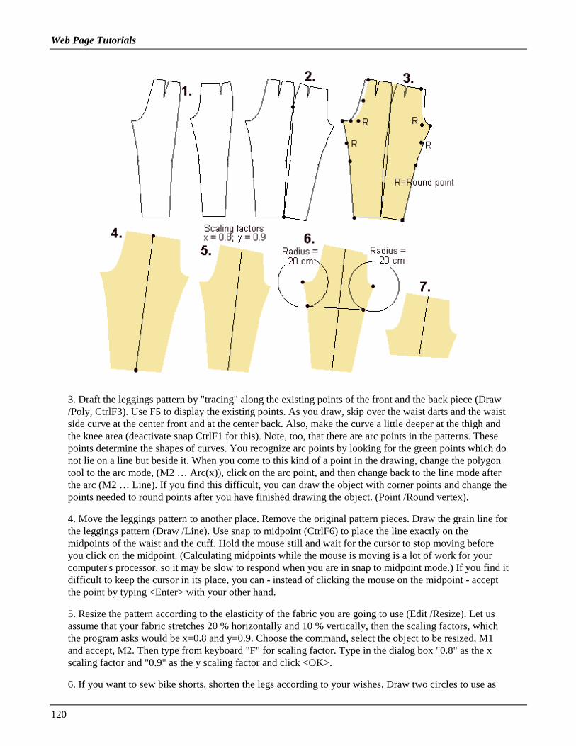
Web Page Tutorials
120
3. Draft the leggings pattern by "tracing" along the existing points of the front and the back piece (Draw/Poly, CtrlF3). Use F5 to display the existing points. As you draw, skip over the waist darts and the waistside curve at the center front and at the center back. Also, make the curve a little deeper at the thigh andthe knee area (deactivate snap CtrlF1 for this). Note, too, that there are arc points in the patterns. Thesepoints determine the shapes of curves. You recognize arc points by looking for the green points which donot lie on a line but beside it. When you come to this kind of a point in the drawing, change the polygontool to the arc mode, (M2 … Arc(x)), click on the arc point, and then change back to the line mode afterthe arc (M2 … Line). If you find this difficult, you can draw the object with corner points and change thepoints needed to round points after you have finished drawing the object. (Point /Round vertex).
4. Move the leggings pattern to another place. Remove the original pattern pieces. Draw the grain line forthe leggings pattern (Draw /Line). Use snap to midpoint (CtrlF6) to place the line exactly on themidpoints of the waist and the cuff. Hold the mouse still and wait for the cursor to stop moving beforeyou click on the midpoint. (Calculating midpoints while the mouse is moving is a lot of work for yourcomputer's processor, so it may be slow to respond when you are in snap to midpoint mode.) If you find itdifficult to keep the cursor in its place, you can - instead of clicking the mouse on the midpoint - acceptthe point by typing <Enter> with your other hand.
5. Resize the pattern according to the elasticity of the fabric you are going to use (Edit /Resize). Let usassume that your fabric stretches 20 % horizontally and 10 % vertically, then the scaling factors, whichthe program asks would be x=0.8 and y=0.9. Choose the command, select the object to be resized, M1and accept, M2. Then type from keyboard "F" for scaling factor. Type in the dialog box "0.8" as the xscaling factor and "0.9" as the y scaling factor and click <OK>.
6. If you want to sew bike shorts, shorten the legs according to your wishes. Draw two circles to use as

Web Page Tutorials
121
guides in drawing the cutting lines. If you want the shorts to be 20 cm long from the crotch, use circleswith a radius of 20 cm. Position the center points of the circles at the front and back crotch points (Draw/Circle, CtrlF3, M1). Type in "20"<Enter>. Repeat for the second circle. Then draw a line which startsand ends at the intersection of the circle and the leg (Draw /Line, CtrlF7). Deactivate snap to intersectionwhen you don't need it any more. It makes your program very slow (CtrlF1).
7. Then cut the pattern with the line you drew (Edit /Cut). Choose the command, choose the object to becut, M1, accept M2, and then the object to cut with, M1, accept M2. Erase the circles and the cutting lineas well as the lower leg piece (Edit /Erase).
Exercise 4: drafting a collar
In this exercise you learn to draft a collar in three different ways: 1) using a frame, 2) typing the points ofthe collar from keyboard and 3) drafting the collar using the Grid points
First make a plan as in the picture below. According to the plan we are going to draft a collar which is 6cm high at the CB (A-J) and which has been curved at the neck 3 cm (from point J downwards). Thecollar is 6 cm high also in the CF (D-E) and its point (D) extends 5 cm to the left from the CF point. Let'sassume that the measured neck circumference of the garment is 40 cm. Then the half length of the collaris 20 cm.
Look at the collar in the picture to notice how it is composed of lines and arcs. At the top edge of thecollar there is a combination of an arc (B-C-D) and a line (A-B). In order make the arc and the line mergeinto one another smoothly, point A has to be on a straight line with the starting point of the arc (B) andthe corner point of the arc (C).
At the bottom edge of the collar there is a combination of two arcs (J-H-G and G-F-E). In order to makethese two arcs merge into one another smoothly, the corner point (H) and the end point (G) of the first archave to be on a straight line with the corner point of the other arc (F).
If you need to know more about arcs, please refer to Web Tutorial 1 (The anatomy of an arc).

Web Page Tutorials
122
Method 1) Drafting the collar in a frame:
Draw a rectangle 20 cm wide and 9 cm high (Draw /Rectangle): Choose the command, click somewhereon the screen with M1 (this will be the left corner of the rectangle E) and type the coordinates of the righttop corner of the rectangle (A) from the keyboard: "@20,9" <Enter>. The "@" sign means that thecoordinates of the latter point are given relative to the given location of the first point (E).
Then draw another rectangle starting from the bottom left corner of the first rectangle using snap to endpoint <CtrlF3>, M1. Type as the relative coordinates of its top right corner (C) "@5,9" <Enter>.
Draw two additional rectangles of size 5x9 cm. The first one starts at the right bottom corner of thesecond rectangle (F) and the other at the right bottom corner of rectangle F.
For the collar tip (D), draw a rectangle of size 5x6 cm starting from point E and going to the left: selectthe starting point of the rectangle at point D, M1 and type the coordinates of the opposite corner of therectangle (D) from keyboard: "@-5,6" <Enter>.
Now you can draw the collar following the points of the frame (Draw /Poly, CtrlF3). Please note that thepoints C, F and H are corner points of an arc. When you come to a corner point, draw the point before thecorner point in the usual way and then change the polygon tool to the X arc mode(M2 … Arc(x)). Whenyou have finished the arc, remember to change the polygon tool back to the line mode (M2 … Line). Ifyou make a mistake, you can undo it and try again (M2 ... Undo last point). If you find this difficult, youcan draw the collar first with all straight lines and change the arc corner points later to round points(Point /Round vertex).
Please note that there is not a point already drawn in the place where you have to draw point G. To placethis point, use snap to intersection, CtrlF7. Change your snap mode back to snap to end point (CtrlF3)after you draw this point, because snap to intersection will slow your computer down.
Method 2) Drafting the collar by typing points in from the keyboard
Here, you are entering exactly the same points as with Method 1), but without the frame to guide you.Select the starting point of the collar (A) anywhere on the screen, M1 and type other points from thekeyboard as follows:
point B: @-5,0 <Enter>, change the polygon tool to arc mode, M2 … Arc(x)point C: @-10,0 <Enter>point D: @-10,-3 <Enter>, change the polygon tool back to line mode, M2 … Linepoint E: @5,-6 <Enter>, change to arc mode, M2 … Arc(x)point F: @5,0 <Enter>point G: @5,1.5 <Enter>point H: @5,1.5 <Enter>point J: @ 5,0 <Enter>, finish, M2 … Done (closed)
Method 3) Drafting the collar along the grid points of the screen
Set the grid spacing to 1 cm using the command Misc /Grid. Activate snap to grid typing CtrlF2. Youshow and hide the grid by typing F4.
Select the starting point of the collar (A) anywhere on the screen, M1. Notice that as you are using snapto grid CtrlF2, the cursor moves from grid point to grid point. Select the rest of the points with mouse(M1) going along the grid points as follows:

Web Page Tutorials
123
point B: count 5 points from point A to the left and click with mouse (M1), then change to arc mode, M2… Arc(x)point C: count 10 points from point B to the left, M1point D: count 10 points to the left and 3 points down, M1, change back to line mode, M2 … Linepoint E: count 5 points to the right and 6 points down, M1, change to arc mode, M2 … Arc(x)point F: count 5 points to the right, M1point G: count 5 points to the right and 1.5 points up (please notice that as we are using a grid 1x1 cm,there isn't any grid point here. Therefore, deactivate snap to grid, CtrlF1, select the point by eye andactivate snap to grid again, CtrlF2)point H: count 5 points to the right and 1.5 points uppoint J: count 5 points to the right, M1, and finish, M2 … Done (closed)
Exercise 5: A long evening skirt
1. Run the skirt macro, giving as the length of the skirt 90 cm (FileMacro, Lskirt.mac). Remove the lining and the waist band (Edit/Erase). Draw guide lines at the front and back waist of the skirt (Draw/Line) as in the picture i.e. three lines per piece and one line for thezipper extension
2. Move the lines 3 cm up (Edit /Move): Choose the command, selectthe lines one by one, M1, M1, M1 … and accept the selection, M2.Type as the starting point of the move "0,0" <Enter>, and as thedestination point of the move "0,3" <Enter>.
3. Using the vertices of the waist and the guide lines draw the patternpieces for the raised waist (Draw Poly, Ctrl F3).
4. To draw waist facings, copy the pattern pieces for the raised waist above the skirt pieces (Edit /Copy)Move the pieces of the facings adjacent to each other (Edit /Move, CtrlF3). Choose the command, thenselect the piece to be moved , M1, accept M2. Give as the starting point of the move one of the edgepoints of the piece, M1 and as the destination point of the move the edge point of the other piece whereyou want the pieces to meet, M1. Join the facing pieces (Edit /Join). After choosing the command selectone of the pieces to be joined, M1, accept M2. Then select the piece next to it, M1, M2. Continue joiningpieces one at a time, selecting the piece which you just joined, M1, M2 and then the piece the be joinedwith it, M1, M2.
5. Join skirt pieces and the pieces for the raised waist. To round the corner of the center front pieces atthe hem, add vertices on the CF line at a distance of 10 cm from the hem and at the hem line at a distanceof 10 cm from CF; use snap to measured distance CtrlF9 or draw guide circles with a radius of 10 cm.Finally, change the center front point of the hem to round point (Point /Round vertex).

Web Page Tutorials
124
Exercise 6: Wraparound skirt
1. Run the basic skirt macro (File /Macro, Lskirt.mac). Erase all pieces but the frontand the back pieces (Edit /Erase).
2. Mirror the front piece (Edit /Mirror). Choose the command, then select the piece,M1, accept M2 and give the center front line of the skirt as the line to be reflectedacross. Draw a vertical line (Draw /Line) starting from the dart apex (CtrlF3) down(CtrlF5) and across the hem line as in the picture.
3. Draw the wraparound piece along the existing vertices (Draw /Poly, CtrlF3). Add points to the CF atthe waist and at the hem. Align the hem CF vertex with vertex of the inner dart apex as in the picture.Use command Point / AlignX; select first the point according which you want to align (= inner dart apex)and then the point to be aligned (= hem CF point).
Note, that in the side seam from hip to waist there is an arc = the top hip (abdomen) vertex is a roundvertex. You can change this vertex to a round vertex afterwards (Point/Round vertex) or you can, whenyou come to this point, change the polygon tool to the arc mode by opening the polygon menu with M2

Web Page Tutorials
125
and choosing from the menu "Arc(x)". When you have finished the arc, change the polygon tool back tothe line mode (M2 … Line).
4. Move the wraparound piece apart from the front piece (Edit /Move) and change the vertex in the hemcorner to a round vertex (Point /Round vertex).Draw the center front line to the wraparound piece (Draw /Line, CtrlF3 and CtrlF5)
Exercise 7: Another wraparound skirt
Run the Lskirt.mac macro (File /Macro). Erase the lining (Edit Erase).Erase the outer vertices of the back piece zipper and the vent extensions.
1. Mirror front piece using the center front line as the reflection line:Choose command Edit/Mirror. Select the front piece M1, accept M2.Select as the top of the reflecting line the waist point of the CF line,(CtrlF3) M1, and as bottom of the reflecting line the hem point of the CFline, M1 Draw guide circles at the waist and the hem points of the centerfront line, radius 10 cm (Draw /Circle, CtrlF3).
2. Draw vertical guide lines between the intersections of the 10 cm circlesand the waist and the hem. Draw new guide circles at the intersection of front hem and the lines you justdrew, radii 3 and 9 cm (Draw /Circle, CtrlF3)
3. a) Draw the right side wrap piece as in the picture, using the existing points of the right side and dart

Web Page Tutorials
126
points of the skirt and the intersection of the 9 cm circle with the right vertical guide line. 3. b) Draw theleft side wrap piece as in the picture using the existing points of the left side and dart points of the skirtand the intersection of the 3 cm circle and the left vertical guide line.
Note that in the side seam from hip to waist there is an arc = the top hip (abdomen) point is a roundvertex. You can change this vertex to a round vertex afterwards (Point/Round vertex) or you can, whenyou come to this point, change the polygon tool to the arc mode by opening the polygon menu with M2and choosing from the menu "Arc(x)". When you have finished the arc, change the polygon tool back toline mode (M2 … Line). When drawing the wrap pieces, be sure to draw one vertex at the waist CF to beable to draw the center line later using this vertex.
Erase all the guide circles (Edit /Erase).
4. Draw 7 cm wide facings at the edges of the wrap pieces: a) Draw a vertical guide line from the top ofthe front edge of the right side wrap piece as in the picture (Draw/Line, CtrlF3, CtrlF5).
b) Copy this line 7 cm to the right and to the left: use command Edit / Copy, select the line to be copied,M1 and accept, M2. Type as the base point of the move "0,0" <Enter> and as the destination point of themove "7,0" <Enter>. Then select the same line and type as the base point of the move "0,0" <Enter> andas the destination point of the move "-7,0" <Enter>.
c) Draw a help line starting at the intersection of the left line and the hem and from there horizontally(CtrlF5) to and across the edge of the piece as in the picture. Use command Draw / Line, choose as thestarting (base) point of the line the intersection of the left line (CtrlF7) and the hem, change to snap toortho (CtrlF5), move the mouse and click when you have moved across the right side guide line.
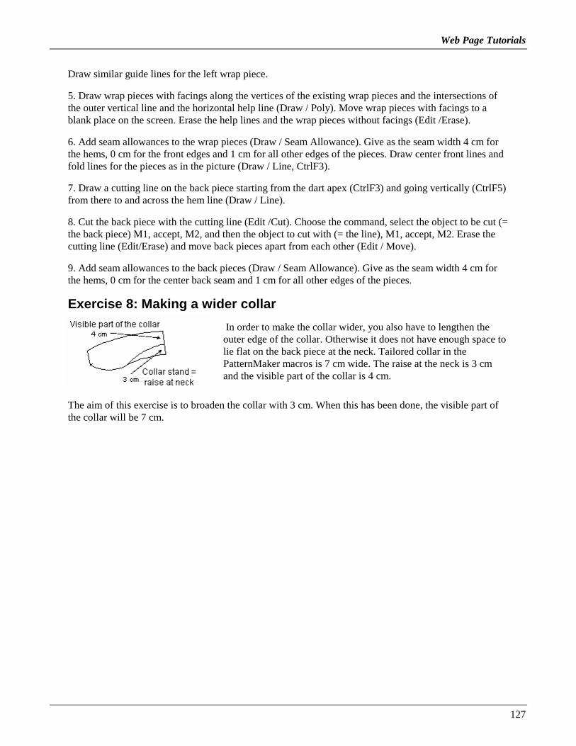
Web Page Tutorials
127
Draw similar guide lines for the left wrap piece.
5. Draw wrap pieces with facings along the vertices of the existing wrap pieces and the intersections ofthe outer vertical line and the horizontal help line (Draw / Poly). Move wrap pieces with facings to ablank place on the screen. Erase the help lines and the wrap pieces without facings (Edit /Erase).
6. Add seam allowances to the wrap pieces (Draw / Seam Allowance). Give as the seam width 4 cm forthe hems, 0 cm for the front edges and 1 cm for all other edges of the pieces. Draw center front lines andfold lines for the pieces as in the picture (Draw / Line, CtrlF3).
7. Draw a cutting line on the back piece starting from the dart apex (CtrlF3) and going vertically (CtrlF5)from there to and across the hem line (Draw / Line).
8. Cut the back piece with the cutting line (Edit /Cut). Choose the command, select the object to be cut (=the back piece) M1, accept, M2, and then the object to cut with (= the line), M1, accept, M2. Erase thecutting line (Edit/Erase) and move back pieces apart from each other (Edit / Move).
9. Add seam allowances to the back pieces (Draw / Seam Allowance). Give as the seam width 4 cm forthe hems, 0 cm for the center back seam and 1 cm for all other edges of the pieces.
Exercise 8: Making a wider collar
In order to make the collar wider, you also have to lengthen theouter edge of the collar. Otherwise it does not have enough space tolie flat on the back piece at the neck. Tailored collar in thePatternMaker macros is 7 cm wide. The raise at the neck is 3 cmand the visible part of the collar is 4 cm.
The aim of this exercise is to broaden the collar with 3 cm. When this has been done, the visible part ofthe collar will be 7 cm.

Web Page Tutorials
128
As seen in the picture, the new length of the outer edge of the collar at back is 17.9 cm which is 5.3 cmlonger than the outer edge of the original collar. So you have to lengthen the outer edge of the collar with5.3 cm.
To draw the above picture:
1. draw the collar stand from the neck shoulder point 3 cm upwards
2. draw the original height of the visible part of the collar from top edge of the collar stand to theshoulder line (use guide circle)
3. draw the new height of the visible part of the collar from top edge of the collar stand to the shoulderline
4. draw arcs starting from the intersection of the visible part of the collar and the shoulder line to thecenter back seam
5. Measure the lengths of the arcs i.e. collar back edges in both situation (Point/Set/Meas.dist)
Draw a cutting line across the collar (Draw/Line).
Cut the collar with the line (Edit/Cut). Select the collar, M1, accept M2, thenselect the line, M1, accept M2. Then rotate one cut piece of the collar in order toadd length to the collar edge. Select the piece to be rotated (in the picture it is theright side piece), M1, accept M2. Choose the point to rotate about with M1,(marked in the picture), the starting (base) point of the rotation (also marked in thepicture), and finally type -5.3 from keyboard. Draw the new shape of the collaralong the existing vertices of the collar pieces (Draw/Poly).
If needed, you can correct the shape of the new collar by moving points manually(Point/Move vertex).

Web Page Tutorials
129
Exercise 9: Drafting a Raglan sleeve
1. Run the basic bodice macro (File /Macro, Lbodice.mac). Erase the center line of the sleeve (Edit/Erase). Move the front and back shoulder darts temporarily to CF and to CB. First, draw cutting linesfrom the dart apexes to and across the CF and CB lines = A-B and C-D (Draw /Line, CtrlF3). Cut thecenter front piece and the back piece with the cutting lines (Edit /Cut). Choose the command, select theobject to be cut (= center front or back piece), M1, accept M2. Then select the object to cut with (=cutting line), M1, accept M2. Cut the other piece the same way.
Cut the sleeve into two pieces: Draw a cutting line upon the sleeve starting from the center point of thesleeve cap and ending at the vertex which is at the center of the sleeve cuff (Draw/Line, CtrlF3). Ifneeded, make the vertices visible with F5. After having drawn the line, cut the sleeve with it (Edit /Cut).Choose the command, select the object to be cut (= the sleeve), M1, accept M2 and the object to cut with(= line), M1, accept M2.
Erase all cutting lines.
2. Rotate the upper piece of the center front piece and the upper piece of the back piece until the shoulderdarts are closed (Edit /Rotate, CtrlF3). Choose the command, select the object to be rotated, M1, acceptM2. Then point the vertex to rotate about (= the dart apex), M1 and the base point of the rotation (= atfront the left side vertex of the shoulder dart at the shoulder and at back the right side vertex of theshoulder dart at the shoulder), M1. Finally, point the destination point of the rotation (= at front the rightside vertex of the shoulder dart at the shoulder and at back the left side vertex of the shoulder dart at theshoulder), M1.
3. a) Measure the distance between vertices E and F = the armscye curve at front. Use the dimension tool(Draw /Dimension, CtrlF3). Choose the command, select one end of the distance to be measured (= E),M1 and then the other end of the distance to be measured (= F), M1. Move the mouse and click the placewhere you want the distance to be displayed. In the picture the distance is 8.1 cm. On the back piecethere is a similar vertex with similar distance from the back armpit vertex.
b) Draw guide circles with a radius of 8,1 cm with the center points at the armpit vertices as in thepicture. (Draw /Circle, CtrlF3). Choose the command, point at the center point of the circle and then type

Web Page Tutorials
130
the radius from the keyboard, 8.1 <Enter>. Add new vertices at the intersection of the circles and thearmscye lines (Point/ Add vertex). Having chosen the command, select the arc where the new vertex is tobe added at the armscye, M1, accept M2. Choose the position of the new vertex using snap tointersection, CtrlF7. We mark these vertices with letters G and H.
4. Move the front (= left) half of the sleeve to a place where vertex F of the front piece and vertex G ofthe front sleeve are one on top of the other. Use command Edit /Move and snap to endpoint, CtrlF3).Choose the command, select the piece to be moved (= the left half of the sleeve), M1 and accept, M2.Point with M1 vertex G as the starting (base) point of the move and vertex F as the destination point ofthe move. Move the back half of the sleeve accordingly.
5. Rotate the front sleeve so that it touches the shoulder tip vertex (Edit /Rotate, CtrlF3). After havingchosen the command select the object to be rotated (= front sleeve), M1 and accept, M2. Choose as thepoint to rotate about vertex F, M1. Click with M1 for the starting point of the rotation anywhere on thescreen, M1. Move the mouse and when the the sleeve head touches the shoulder tip, click with M1 forthe destination of the rotation. Rotate the back sleeve accordingly.
6. Draw the raglan sleeves along the existing vertices. Please refer to the picture to see vertices of thesleeve to be drawn. Use command Draw /Poly. Choose the vertices of the polygon one by one, M1, M1,M1… When you have pointed all the vertices and come to the last but one vertex, open the polygonmenu with M2 and choose the option "Done (closed)". When drawing use the snap which you find bestin the situation in question, CtrlF3 or CtrlF4 or no snap. You can draw the arcs "angular" and change thevertices in question later to round vertices (Point/Round vertex).
7. Draw the new front and back pieces accordingly (Draw /Poly, CtrlF3). Go along the existing vertices.Draw the front pieces in three separate pieces i.e. upper part of the center front piece, the lower part ofthe center front piece and the front side piece. Draw the back piece also in three separate pieces i.e. theupper part of the center back piece and the lower part of the center back piece and the back side piece.

Web Page Tutorials
131
8. Rotate the upper part of the center front piece to close the temporary dart at the CF (Edit /Rotate,CtrlF3). Choose the command, select the object to be rotated (=the upper part of the center front piece),M1, accept M2. Choose the dart apex as the point to rotate about, M1, the upper vertex of the dart at theCF line as the starting point of the rotation, M1 and the lower vertex of the dart at the CF as thedestination point of the rotation, M1. Rotate accordingly the upper part of the center back piece to closethe temporary dart at the CB and to move it to the shoulder. Join the front and back center pieces togetherinto whole pieces.
Exercise 10: Drafting patterns for an overall
1. a) First make preparations for the top part of the overall and run the basic bodice macro (File /Macro,Lbodice.mac). Erase all other pattern pieces but the front and the back pieces. Do not erase the back dartpiece. Use command Edit /Erase, select all the pieces to be erased one by one, M1, M1, M1…, acceptand execute the command with M2.
b) Draw a line to cut the pieces at the waist level as in the picture (Draw /Line, CtrlF3). Start the line atthe CF waist point and end at the CB waist point. Then cut the pieces with the line (Edit /Cut): Choosethe command, select the CF piece, M1, accept M2, then select the cutting line, M1, accept and executethe command M2. Cut the same way also the front side piece and the back piece as well as the back dartpiece. Erase the cutting lines and all pieces under the waist level (Edit /Erase). Select all the pieces to beerased one by one, M1, M1, M1... , accept the selection and execute the command with M2.

Web Page Tutorials
132
2 a) Start designing the front pieces. Draw a cutting line on the front side piece as in the picture (Draw/Line), starting from the bust apex (CtrlF3) and ending outside the side seam. Cut the front side piecewith the line (Edit /Cut). Choose the command select the piece to be cut (= the front side piece), M1,accept M2 and then the piece to cut with (= cutting line), M1, accept M2. Erase the cutting line (Edit/Erase).
b) Rotate the top part of the front side piece to close the bust/shoulder dart and to open it to the side seam(Edit /Rotate). Choose the command, select the piece to be rotated (= top piece of the front side piece),M1, accept M2. Select the point to rotate about (it is marked in the picture) (= bust apex), M1, then selectthe base point of the rotation (also marked in the picture, M1 and finally the destination point of therotation, M1.
c) Join the front pieces together into one piece (Edit /Join): Choose the command, select the CF piece,M1, accept M2, then select the top side piece, M1, accept M2. Finally select the piece you joined, M1,accept M2 and the remaining bottom part of the side piece, M1, accept M2. Add ease to the front pieceby moving the vertices as in the picture i.e. 2 cm to the right. Choose command Point /Move vertex.Select the points to be moved with a selection window, it is shown in the picture. The selection windowis activated by the selection window icon or typing "W" from the keyboard after you have chosen themove vertex command. Choose the left top corner of the selection window with M1, move the mouse andpoint the right bottom corner of the selection window with M1 (refer to the picture). Accept the selectionwith M2. Then type as the base point of the move "0,0" <Enter> and as the destination point of the move"2,0" <Enter>.

Web Page Tutorials
133
3 a) Make a mirror copy of the back piece so it faces in the same direction as the pants back piece (Edit/Mirror). Choose the command, select the piece to be mirrored (= back piece), M1, accept M2. Thengive, as the top point of the line to be reflected across, the CB neck point, M1 and as the bottom point ofthe line to be reflected against, M1. Erase the original back piece (Edit /Erase). b) In order to add ease tothe back piece, move the points marked in the picture 2 cm to the right the same way you moved thepoints in the front piece (Point /Move vertex). Use a selection window as illustrated in the picture.
4. Now start designing the pants part of the overall. Run the pants macro (File /Macro, Lpants.mac).Erase center lines, pocket mouth line, waist band and the zipper extension (Edit /Erase).
5. Add to the front and the back pants 2 cm ease in the same way you did in the top parts (Point /Movevertex). Use a selection window illustrated in the picture.
6. a) Move the top back piece to touch the pants' back piece, so that their CB waist points lie on top ofeach other (Edit /Move, CtrlF3). Choose the command, select the piece to be moved (= back top piece),M1, accept M2. Choose as the base point of the move the CB waist vertex of the top, M1 and as thedestination of the move the CB waist point of the back pant, M1.
b) Rotate the top piece so that its waist is on the back pants' waist (Edit /Rotate, CtrlF3). After havingchosen the command select the piece to be rotated (the top piece), M1, accept M2. Choose the CB waistvertex of the top piece as the center point of the rotation (the point to be rotated about), M1, the waistside vertex of the top as the base point of the rotation, M1 and the waist side vertex of the pant as thedestination of the rotation, M1. These points are marked in the picture 6a.
c) To add vertical ease at the waist of the overall, move the back top piece 2 cm up (Edit /Move). Choosethe command, select the piece to be moved (= back top), M1 and accept, M2. Give as the base point ofthe move from keyboard "0,0" <Enter> and as the destination of the move "0,2" <Enter>.
d) Rotate the back top so that you get an additional vertical ease at the CB waist (Edit /Rotate). Afterhaving chosen the command select the piece to be rotated (= back top), M1 and accept, M2. Give the side

Web Page Tutorials
134
vertex of the top waist as the center point of the rotation, M1 and the CB vertex of the top waist as thebase point of the rotation, and type the distance to be rotated from keyboard "-2" (the distance is anegative number because the rotation is to be done clockwise) <Enter>. The points are marked in thepicture6c.
7. a) Now move the front top piece so that it touches the front pant at waist, the CF vertexes lie on top ofeach other (Edit /Move, CtrlF3). Choose the command, select the piece to be moved (= the front top),M1, accept M2. Give as the base point of the move the CF waist vertex of the top, M1 and as thedestination of the move the CF waist vertex of the front pant, M1.
b) Add 2 cm vertical ease at the waist. Move the front piece up by this amount (You do not need to selectthe command as it already is active). Select the front top, M1, accept M2. Type as the base point of themove from the keyboard "0,0" <Enter> and as the destination point of the move "0,2" <Enter>.

Web Page Tutorials
135
8. Finally, draw the overall following the existing points (Draw /Poly, CtrlF3). Show vertices by typingF5. Do not go through the waist vertices. Go directly from the hip point to the armpit point (back) andfrom the hip point to the bust dart point (front). Please notice that there are arcs and lines in the patterns.When you arrive at a point where an arc begins, open the polygon menu with M2, and choose from theoptions (Arc(x). After having given the points for the arc (start, corner, end) - and if there is not anotherarc after the first one, change the polygon tool back to the line mode (M2 … Line). If you find thisdifficult, you can draft the patterns with all straight lines (= without changing to arc mode) and changethe arc corner points afterwards to Round points with Point /Round vertex.
After you have drafted the front and the back pieces of the overall, erase all the original pieces(Edit/Erase). Draw grain lines on the pieces (Draw /Line, GtrlF5).
Draw a collar for the overall if you want one. You can use the collars macro. Before drafting the collar,make the neck opening of the overall 1 cm bigger in all directions (Point /Move vertex). This exercise isbased on the patterns of the basic sloper and it does not have enough ease at neck for a real garmentpattern. After making the neck opening bigger, measure its length at front and at back (Point/Set/Meas.dist) and multiply the result by 2 to get the whole neck circumference. You will use thismeasurement in the collars macro.
In a real designing situation you would not have removed the sleeves at the beginning. Please notice thatif you want the overall to have sleeves you have to make the armscyes bigger, too. You have to lower thearmscye of the bodice and broaden the sleeve at the armpit by the same amount. This makes the sleevelarger at the armscye.
Alternatively you can use another macro for the top of the overall - e.g. the blouse macro or the jacketmacro. These macros already have the needed ease at the neck opening and at the armscyes and thesleeves. Using these macros, you need to add ease only to the pants part of the overall.
Exercise 11: A flared collar
1. Use the basic bodice macro for this exercise (File /Macro, Lbodice.mac). Erase thesleeve and its center line (Edit /Erase). Rotate the front side piece so that theshoulder/bust dart is closed (Edit /Rotate, CtrlF3). The center point of the rotation isthe dart apex point, the base point of the rotation is the right side point of theshoulder/bust dart points on the shoulder, and the destination point of the rotation isthe left side point of the shoulder/bust dart points on the shoulder.
Design the shape of the collar upon the front piece the collar (Draw/Polygon). For this purpose drawguide circles at the front neck shoulder point (radius 10) and the front neck CF point (radius 14 cm)(Draw /Circle, CtrlF3, 14<Enter>)

Web Page Tutorials
136
Using the guide circles draw the shape of the front collar (Draw /Poly, CtrlF3). Refer to the picture.Notice that there are arcs and lines in the collar. In the picture the arc corner points (round points) aremarked with letter "R". When you come to the starting point of an arc, change the polygon tool to arcmode by opening the polygon menu with M2 and choosing the option "Arc (X)".
2. Draw guide circles (Draw /Circle, CtrlF3) and the shape of the back collar on the back piece (Draw/Poly, CtrlF3).
3. Move the front and the back collar so that they touch each other at their joint shoulder vertex as in thepicture (Edit /Move, CtrlF3). Rotate the back collar so that you get a joined collar (Edit /Rotate, CtrlF3).The center, base and destination points have been marked in the picture.
4. Join the pieces (Edit/Join). If needed, correct the shape of the collar in the place which is marked inthe picture with an arrow by moving a point (Point /Move vertex).
5. Draw cutting lines on the collar (Draw /Line).
Cut the collar with the lines (Edit /Cut): Choose the command, select the piece to be cut (= the collar),M1, M2, and then the piece to cut with (= the line), M1, M2. Then cut the remaining pieces of the collarwith the remaining cutting lines similarly. Erase the cutting lines (Edit /Erase).
6. Rotate the pieces of the collar so that the outer edge of the collar opens (= increases) by 2.5 cm at eachintersection of the collar edge and the cutting lines (Edit /Rotate). Choose the command, select thetopmost piece of the collar, M1, accept M2. Choose the center point of the rotation as in the picture, M1,M2 and type the rotation distance from keyboard "2.5" <Enter>. Continue to rotate all the collar pieces

Web Page Tutorials
137
similarly.
7. Finally join the pieces of the collar together into one piece (Edit /Join). Choose the command, selectthe topmost of the pieces, M1, accept M2 and the second from the top, M1, M2. Select again the topmostpiece (= which now is a combination of the two joined top pieces), M1, M2 and the next piece, M1, M2.Join the collar piece by piece in this way.
Exercise 12: A draped dress
1. Use the dress macro for this exercise (File /Macro, Ldress.mac). Erase the sleeve,the back pieces and the facings. Make a mirror copy of the front pieces (Edit /Mirror,CtrlF3). Choose the command, select the front pieces, M1, M1 and accept, M2. Thenchoose as the top end of the reflection line the CF line top (= the neck) vertex, M1,and as the bottom end of the reflection line the CF bottom (= the hem) vertex, M1
2. Draw a cutting line across the mirrored front side piece as in the picture (Draw/Poly, CtrlF3). Because you need more than two vertices for the line, you have to usethe polygon tool and not the line tool. Select as the starting point of the line any pointoutside the armscye, M1, as the second point of the line the bust apex point, M1 andas the end point of the line any point outside the original front side piece, M1, open
the polygon menu with M2 and conclude the command by choosing "Open (done)" from the options. Cutthe mirrored front side piece with this line (Edit /Cut). Choose the command, choose the object to be cut(= mirrored front side piece), M1, accept M2 and then the piece to cut with (= the cutting line), M1, M2.
3. Transfer the dart by rotating the topmost of the cut pieces so that the shoulder dart is closed and a dartopens up at the armscye (Edit /Rotate, CtrlF3).
Join all front pieces except the original front side piece into one piece (Edit /Join).

Web Page Tutorials
138
4. Draw cutting lines across the joined front pieces as in the picture (Draw /Line). All the lines have toextend beyond the edges of the piece. Notice that one cutting line has to go through the bust apex. Usesnap to end point (CtrlF3) to be exact. Cut the piece with the lines that you drew (Edit /Cut).
5. a) Rotate the pieces so that the dart which was moved to the armscye is closed and so that
b) each intersection of the cutting lines is opened to 5 cm. The center and base points of the rotation havebeen marked in the picture. The distance of the rotation is given by typing from the keyboard "5"<Enter>.
Exercise 13: A corset from a basic bodice
1. Run the basic bodice macro (File /Macro, Lbodice.mac). Decrease 2 cm of ease onthe front and the back pieces. (The whole circumference is thus decreased by 8 cm i.e.the ease that has originally been added to the body measurements in the basic bodicepatterns). Decrease the ease by moving points (Point /Move vertex). Choose all thevertices that are to be moved in the same direction at one time, M1, M1, M1 …accept, M2. Give as the base point of the move "0,0" from keyboard and as thedestination point of the move "2,0" (moving to the right) or "-2,0" (moving to the left)<Enter>. Move the back piece and its waist dart to touch the front piece at the armpit
vertex (Edit/Move). Use snap to end point (CtrlF3) to be exact.
Draw a circle with 8 cm radius and center point at the bust apex, and a circle with 2 cm radius and centerpoint at the joint armpit vertex of the front and the back pieces (Draw /Circle, CtrlF3). Choose the center

Web Page Tutorials
139
point of the circles and type the radius from keyboard "8" or "2" <Enter>.
2. Draw the corset patterns according to the picture along the existing vertices (Draw /Poly, CtrlF3).Round points (corner points of an arc) have been marked with "R" in the picture. Draw the shoulderstraps (Draw /Line or Draw /Poly). Erase the guide circles.
Exercise 14: A jacket with a side panel
1. Run the jacket macro (File /Macro, Ljacket.mac). Move the pieces so that they touch each other at hem(Edit /Move, CtrlF3). a) Draw vertical lines starting at the vertices on the armscye lines as in the pictureand ending outside (down) from hem (Draw /Line). Use snap to end point (CtrlF3) to grab the armscyevertices and then snap to ortho (CtrlF5) to draw vertical lines. b) Draw a polygon around the areabetween the side seams of the front and the back piece (Draw /Poly, CtrlF3). Go along the existingvertices and use snap to end point (CtrlF3). At the waist of the side seam there are three vertices; thecenter one is a round vertex. You need not draw all these vertices; just draw one (line) point at the centervertex as in the picture. c) In the same way, draw a polygon around the back waist dart (Draw /Poly,CtrlF3).
2. Move the polygons horizontally so that their new positions are on the lines that you drew down fromthe armscyes (Edit /Move, CtrlF3). Choose the Move command, select the polygon drawn between theside seams, M1, accept M2. Give as the base point of the move the joint hem point of the front and theback piece (CtrlF3), M1, and as the destination point of the move the intersection (CtrlF7) of the verticalline and hem (CtrlF7), M1. Move the other help polygon similarly, now to the line drawn down from theback armscye. The base point of the move is now the intersection (CtrlF7) of the line down from the back

Web Page Tutorials
140
waist dart with the hem line, and the destination of the move is the intersection of the line drawn downfrom the back armscye with the hem line.
Draw the new shapes of the front, back and side pieces following the existing points (Draw /Poly,CtrlF3). Draw the front center and the front side pieces as two separate pieces. Draw the back piece asone piece with a shoulder dart. Draw the side panel in one piece. (You can see the shape of the side panelin picture 3).
3. The shapes of the pieces are not quite satisfactory: The back piece does not curve enough at the waistcompared with the front piece. The side panel is somewhat distorted. Therefore, move the waist verticesof the pieces as shown in the picture: the waist vertices of the front side and the back pieces(simultaneously) to the right and the waist vertices of the side panel (simultaneously) to the left (Point/Move vertex). You can do this by eye. First use the snap to end point (CtrlF3) to select the vertices to bemoved and then snap to ortho (CtrlF5) to move the vertices horizontally. When moving the points in thisway "in pairs" the move of the points does not change the waist circumference of the garment
4. Draw a cutting line on the front side piece at the top hip (abdomen) level (Draw/Line, CtrlF3, CtrlF5).The line must extend over both edges of the piece.
Cut the side piece with the line (Edit /Cut). Choose the command, first choose the object to be cut (= theside panel), M1, accept M2 and then the object to cut with (= the cutting line), M1, accept M2. Erase thecutting line (Edit /Erase). Rotate the topmost piece of the front side pieces so that the shoulder dart isclosed (Edit /Rotate, CtrlF3). The center, base and destination points have been marked in the picture. Inthis kind of a jacket design the pocket is positioned on this cutting line. After you have sewn the frontwaist dart, close the cutting line temporarily with zigzag stitches. Iron a strip of interfacing on its wrong

Web Page Tutorials
141
side. When fastening the pocket you will cut the pocket mouth along this line. If you are sewing a patchpocket, position it so that the cutting line is hidden under the pocket.
Exercise 15: Drafting facings
Facings are drafted using two Snap modes -- Snap to End Point (CtrlF3) and Snap to Offset(CtrlF8). Snap to End Point is used to draw along the existing points of the original pattern piece(e.g. points 1-6 of the CF facing in the picture) to create the outside edge(s) of the facing, and Snapto Offset is used to draw the points that form the inside edge(s) (e.g. points 7-11 of the CF facing inthe picture).
Lets assume that you want to draft facings which are 2" wide. Select the command Draw/Polygonfrom the main menu. Start by clicking with the left mouse button (M1) on the vertices that are sharedwith the original pattern piece and the facing (e.g. points 1-6 of the CF-facing in the picture).Usesnap to end point CtrlF3.
Then change the snap mode to Snap to OffsetCtrlF8. In this snap mode two distances areasked. If you want to define a vertex which is2" from a vertex of the original pattern pieceand on the line of the original piece (e.g. pointnumber 7 in the CF-facing in the picture, whichis 2" from vertex 6 and on the hem line of theoriginal pattern piece), type as the distances 2and 0 (or 0 and 2; the order of the distancesdoes not matter) and click <OK>. Move themouse cursor near point 6. You will notice that
you have a choice of 4 vertices which are all 2" from point 6 and on a line (or an extension of theline) forming the original pattern piece. When you move the mouse the cursor blinks as a yellowcross on these 4 points. Choose the point that corresponds to point 7 in the picture.
Points 8-10 are not on a line of the original pattern piece. So you have to change both of the snap
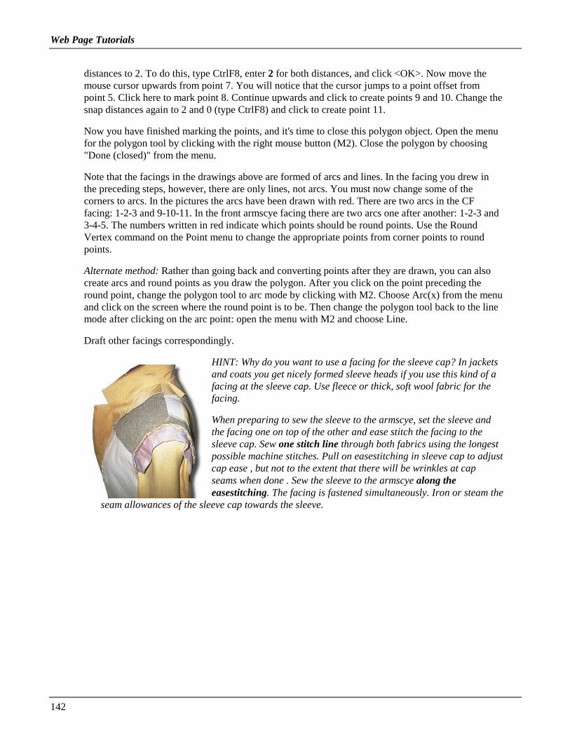
Web Page Tutorials
142
distances to 2. To do this, type CtrlF8, enter 2 for both distances, and click <OK>. Now move themouse cursor upwards from point 7. You will notice that the cursor jumps to a point offset frompoint 5. Click here to mark point 8. Continue upwards and click to create points 9 and 10. Change thesnap distances again to 2 and 0 (type CtrlF8) and click to create point 11.
Now you have finished marking the points, and it's time to close this polygon object. Open the menufor the polygon tool by clicking with the right mouse button (M2). Close the polygon by choosing"Done (closed)" from the menu.
Note that the facings in the drawings above are formed of arcs and lines. In the facing you drew inthe preceding steps, however, there are only lines, not arcs. You must now change some of thecorners to arcs. In the pictures the arcs have been drawn with red. There are two arcs in the CFfacing: 1-2-3 and 9-10-11. In the front armscye facing there are two arcs one after another: 1-2-3 and3-4-5. The numbers written in red indicate which points should be round points. Use the RoundVertex command on the Point menu to change the appropriate points from corner points to roundpoints.
Alternate method: Rather than going back and converting points after they are drawn, you can alsocreate arcs and round points as you draw the polygon. After you click on the point preceding theround point, change the polygon tool to arc mode by clicking with M2. Choose Arc(x) from the menuand click on the screen where the round point is to be. Then change the polygon tool back to the linemode after clicking on the arc point: open the menu with M2 and choose Line.
Draft other facings correspondingly.
HINT: Why do you want to use a facing for the sleeve cap? In jacketsand coats you get nicely formed sleeve heads if you use this kind of afacing at the sleeve cap. Use fleece or thick, soft wool fabric for thefacing.
When preparing to sew the sleeve to the armscye, set the sleeve andthe facing one on top of the other and ease stitch the facing to thesleeve cap. Sew one stitch line through both fabrics using the longestpossible machine stitches. Pull on easestitching in sleeve cap to adjustcap ease , but not to the extent that there will be wrinkles at capseams when done . Sew the sleeve to the armscye along theeasestitching. The facing is fastened simultaneously. Iron or steam the
seam allowances of the sleeve cap towards the sleeve.

Web Page Tutorials
143
Exercise 16: Drafting a hood
1. Measure the neck circumference of the garment (not yourneck circumference). Divide it by 2.
2. Draw a rectangle with size 1/2 of the garment neckcircumference x 35-40 cm = points A-B-C-D
3. Draw a circle at the upper right corner of the rectangle withradius 8 cm
4. Add points as follows:
- midway between points A and D = point E- 8 cm from point B to the left = point F- 8 cm from point B downwards = point G- midway between points C-D = point H, use snap to mid point(CtrlF2)- midway between points C-H = point J- midway between points D-K = point L- midway between points H-L = point K
5. Move point A 2 cm to the left. Move points D and L 3 cmdown- move point K 1.5 cm down
6. Change points B, E, H and L to round points (Point/Round Vertex)
More exercises
On the following pages you have some exercises without specific instructions. Look carefully at thepictures, we are sure you can do these exercises, too. Use as your basic blocks the basic bodice or anothermacro, according to your wishes. Be certain to have the needed ease in the garment.

Web Page Tutorials
144
Exercises 17 and 18: Two corset tops for evening dresses

Web Page Tutorials
145
Exercise 19: A long evening dress and a bolero

Web Page Tutorials
146
Exercise 20: Drafting a flat collar
Exercise 21: A closely fitting evening jacket
Use the jacket minimum ease patterns = 12 cm bust ease as base for this design

Web Page Tutorials
147
ADVANCED TUTORIAL: GRADING
Creating a general grading table to be used together withPatternMaker macro patterns(Note: This tutorial applies to the Expert and Marker Versions only.)
You can use the basic bodice macro of PatternMaker to draft slopers in different sizes and to generate ageneral grading table with them. (Macros are small computer programs that you run with PatternMaker todraft patterns to given measurements). The procedure is very simple and you do not need to knowanything about the grading.
PatternMaker macros have been programmed using the Scandinavian pattern drafting system. Thereforeyou need to use the Scandinavian default measurements for grading the patterns you have drafted with it.(These measurements are given at the end of this section.) To read more about the program and themacros go to my main page:
www.leenas.com.
Run the basic bodice macro in two sizes, one smaller (e.g. size 40) and one the next bigger (size 42).Position the pattern pieces so that they meet at CF and CB lines and at hem. Then draw the gradingarrows from the vertices of the smaller size to the corresponding vertices of the bigger size. Use snap toend point to be exact (CtrlF3).
You have to use the Scandinavian measurements , other standard measurements sets might not have allthe measurements needed. To convert the Scandinavian sizes into the American ones, compare the bustcircumference measurements.
Follow the instructions below:
Run the basic bodice macro with the default measurements (Scandinavian 42) on layer 1. Before runningthe macro change layer 1 to be the current layer. Click on the black box at the top part of the screen withLayer0 text on. Then click in the current column of layer 1 in the dialog box opened. Click "Done" toaccept the choice.
Then run the basic bodice macro with the measurements for Scandinavian size 40 to layer 0. Use themeasurements in the attached table. Before running the macro change layer 0 to the current layer.
Move the pattern pieces so that they meet at the CF and the CB lines and at hems. Move the sleeve pieces

Web Page Tutorials
148
so that they meet at the left side cuff vertex. Remember to choose also the center line of the sleeve whenyou do the moving.
Draw grading arrows from the vertices of the smaller size to the vertices of the bigger size. First pointthe vertex of the smaller size with the left button of the mouse and accept the choice with the right buttonof the mouse. Then point the corresponding vertex of the bigger size with the left button of the mouseand accept the choice with the right button of the mouse. Use snap to end point to be exact (CtrlF3). It isenough to add grading arrows to the corners of the pieces.
E.g. in the back piece you should add grading arrows to the following vertices:
• Back side hem vertex
• Armpit vertex of the armscye
• Shoulder tip at the armscye
• Shoulder vertex at the neck opening
• Back neck point at the neck opening
Add grading tacks to the following vertices of the back piece:
• The hem point of the CB
• The CB point which is on the same vertical level with the armpit vertex i.e. the last but onevertex before the neck vertex on the CB line from hem to neck.
Add grading arrows to all vertices of the back waist dart.
• Add the sleeve grading arrows to the
• Armpit vertices and to
• the shoulder vertex of the sleeve cap.
Add a grading tack to the left cuff point. Add grading arrows to both ends of the sleeve center line.

Web Page Tutorials
149
Please note that you have to add grading tacks to the vertices which are one on top of each other in bothsizes. Because a grading tack "is valid" to the following grading tack, it is enough to add grading tacks tothe utmost of these vertices. Read more about adding grading arrows and tacks from the PatternMakeruser's manual.
After having added all the grading arrows and tacks run command Grade/Grade on layer 0. Whenchoosing the pieces to be graded, choose the pieces of the smaller size. You can choose all the pieces oneby one for simultaneous grading. After having chosen all the pieces clicking on them with the left buttonof the mouse, confirm the choice with the right button of the mouse. Type as the amount of sizes to begraded e.g. and leave the increment to
This way you would get pattern pieces to Scandinavian sizes 42, 44, 46 and 48. On layer 1 there will bethe patterns for size 42 two times: the ones you drafted at the beginning of this exercise running themacro with the default measurements and the graded ones. If you have added the grading arrows andtacks correctly the pattern pieces are exactly the same. If not, you have made a mistake. Check thegrading arrows and tacks.
Please note that in real life the grading rules from size 40 to 48 are not consistent. So the patterns gradedin this exercise are not correct. To make a correct grading table for all the sizes run the basic bodicemacro with the measurements of all the sizes by turns. The lengths of the grading arrows can then bemeasured from the basic bodices in different sizes.
The simplest way to make a grading table to be used with the PatternMaker patterns is to make a gradingtable with sizes 40 and 42 and open it in a text editor giving the grading rules for other sizes typing themin the table. This grading table can be read to any patterns drafted with the PatternMaker macros for topgarments (jackets, dresses, blouses, vests).
Create a similar grading table for the skirts and for the pants.
Copyright 1998 Leena Lahteenmaki
The following measurements are given in centimeters:
Size (European) C38 C40 C42 C44 C46Bust 88.0 92.0 96.0 100.0 104.0Waist 70.0 74.0 78.0 82.0 86.0Abdomen 89.0 92.0 95.0 99.0 103.0Hip 96.0 99.0 102.0 106.0 110.0Back Length 40.9 41.1 41.3 41.5 41.7Back Width 35.6 36.6 37.6 38.6 39.6Neck Circum. 37.8 38.5 39.3 40.0 40.8Shoulder 13.1 13.3 13.5 13.7 13.9Bust Height 34.8 35.8 36.8 37.8 38.8Waist Height 51.8 52.6 53.4 54.2 55.0Arm Length 60.0 60.2 60.4 60.6 60.8Biceps 28.0 29.0 30.0 31.0 32.0Wrist 17.5 18.0 18.5 19.0 19.5

Web Page Tutorials
150

151
INDEX(Please note: this Index does not reference the Web Tutorials.)
Aabsolute coordinates......................................................... 13ADD ARROW command................................................. 40ADD TACK command..................................................... 41ADD VERTEX command................................................ 33ALIGN-X command......................................................... 34ALIGN-Y command......................................................... 34angles
used in polar coordinates............................................. 15ARRANGE MARKER command .................................... 65arranging a marker ........................................................... 65
Bbase point ......................................................................... 19buttonholes....................................................................... 51
Ccanceling a command ....................................................... 22CHANGE OBJECT command ................................... 22, 57changing drawing color.................................................... 58changing line style............................................................ 57changing the current layer ................................................ 47changing the shape of a curve .......................................... 31CIRCLE command........................................................... 35CLOSE OBJECT command ............................................. 22COLOR command............................................................ 35commands
ADD ARROW............................................................. 40ADD TACK................................................................. 41ADD VERTEX............................................................ 33ALIGN-X .................................................................... 34ALIGN-Y .................................................................... 34ARRANGE MARKER................................................ 65canceling...................................................................... 22CHANGE OBJECT............................................... 22, 57CIRCLE....................................................................... 35CLOSE OBJECT......................................................... 22COLOR ....................................................................... 35COPY .......................................................................... 22CORNER VERTEX .................................................... 33CREATE SYMBOL command ................................... 53CUT....................................................................... 25, 60CUT RATIO.......................................................... 62, 65DEFINE PIECE........................................................... 63DELETE SEGMENT .................................................. 33DELETE VERTEX ............................................... 32, 33DIM............................................................................. 36DIM SETTINGS ......................................................... 37DOT....................................................................... 28, 36EDIT ARROW ............................................................ 41
Edit menu.....................................................................21ERASE.........................................................................22EXIT ..............................................................................9EXPAND .....................................................................22EXPLODE ...................................................................54GRADE........................................................................44JOIN.............................................................................27LAYER ........................................................................46LINE ......................................................................16, 24LOAD GROUP............................................................55LOAD OBJECT...........................................................55LOAD SYMBOL.........................................................51MARKER REPORT ....................................................68MIRROR......................................................................22MOVE .........................................................................18MOVE VERTEX.............................................30, 31, 33OFFSET.......................................................................57OPEN...........................................................................10PACK LEFT/UP/DOWN.............................................67PAN .......................................................................11, 14PATTERN ...................................................................35Points menu .................................................................33POLY...........................................................................14PRINT MARKER........................................................69PURGE ........................................................................55READ TABLE.............................................................43RECT.................................................................8, 13, 40repeating ..................................................................9, 20RESIZE........................................................................21ROTATE......................................................................21ROTATE VERTEX .....................................................33ROUND VERTEX ......................................................33running...........................................................................8SAVE...........................................................................16SAVE TABLE .............................................................42SEAM ALLOWANCE ..........................................56, 60SELECT LIBRARY ....................................................50SET MARKER AREA.................................................64SET/MEASURE DIST ................................................34TEXT...........................................................................38UNDO..........................................................................20ZOOM ...................................................................10, 14ZOOM ALL.....................................................11, 13, 33
coordinatesabsolute........................................................................13polar .............................................................................15relative .........................................................................14
COPY command...............................................................22CORNER VERTEX command.........................................33CREATE SYMBOL command.........................................53curve
changing shape.............................................................31curves
drawing ........................................................................14CUT command............................................................25, 60

Index
152
CUT RATIO command .............................................. 62, 65
DDEFINE PIECE command............................................... 63defining marker pieces ..................................................... 63DELETE SEGMENT command ...................................... 33DELETE VERTEX command ................................... 32, 33destination ........................................................................ 19DIM command ................................................................. 36DIM SETTINGS command.............................................. 37Dimension objects............................................................ 36
changing settings ......................................................... 37DOT command........................................................... 28, 36drawing curves ................................................................. 14drawings
opening........................................................................ 10restoring from disk ...................................................... 22saving .......................................................................... 16viewing ........................................................................ 10
EEDIT ARROW command ................................................ 41edit functions.................................................................... 18Edit menu commands ....................................................... 21entering input
by mouse ....................................................................... 8by typing...................................................................... 13
ERASE command ............................................................ 22EXIT command.................................................................. 9EXPAND command......................................................... 22EXPLODE command....................................................... 54
Ffill pattern
changing ...................................................................... 35function keys .................................................................... 11
GGetting Started ................................................................... 3GRADE command ........................................................... 44grading
adding arrows .............................................................. 40adding tacks................................................................. 41create a grading table................................................... 42editing arrows.............................................................. 41establishing grading rules ............................................ 40grading a pattern.......................................................... 44loading grading rules ................................................... 43sample (rectangle) ....................................................... 40saving grading rules..................................................... 42
grading arrowsshowing/hiding ............................................................ 12
gridshowing/hiding ...................................................... 11, 15
grouping objects............................................................... 20
Hhiding/showing
grading arrows .............................................................12grid.........................................................................11, 15layers............................................................................48points (vertices)................................................11, 30, 36
Hot Keys...........................................................................10
Iicons ...................................................................................7inputs
entering by typing ........................................................13entering with mouse.......................................................8
insertion point (Symbols) .................................................53Installing PatternMaker ......................................................3
JJOIN command.................................................................27
Llabels (text)
adding to drawing ........................................................38LAYER command ............................................................46layers
changing default colors ................................................47changing the current layer............................................47description ...................................................................46naming .........................................................................47resetting defaults ..........................................................48showing/hiding ............................................................48the LAYERS dialog box ..............................................46
LINE command ..........................................................16, 24line style
changing.......................................................................57LOAD GROUP command ................................................55LOAD OBJECT command ...............................................55LOAD SYMBOL command .............................................51
Mmarker mode .....................................................................63MARKER REPORT command ........................................68markers
arranging ......................................................................65defining pieces .............................................................63marker report................................................................68packing pieces..............................................................67printing.........................................................................69setting cut ratio ......................................................62, 65setting marker area .......................................................64
menu bar .............................................................................7MIRROR command..........................................................22modifying polygons ..........................................................35MOVE command..............................................................18MOVE VERTEX command .................................30, 31, 33
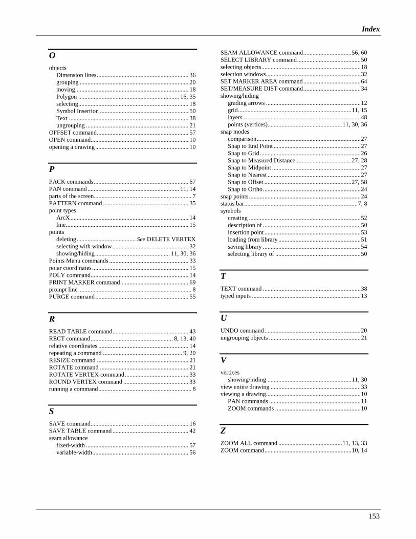
Index
153
Oobjects
Dimension lines........................................................... 36grouping ...................................................................... 20moving......................................................................... 18Polygon ................................................................. 16, 35selecting....................................................................... 18Symbol Insertion ......................................................... 50Text ............................................................................. 38ungrouping .................................................................. 21
OFFSET command........................................................... 57OPEN command............................................................... 10opening a drawing............................................................ 10
PPACK commands............................................................. 67PAN command ........................................................... 11, 14parts of the screen............................................................... 7PATTERN command ....................................................... 35point types
ArcX............................................................................ 14line............................................................................... 15
pointsdeleting...................................... See DELETE VERTEXselecting with window................................................. 32showing/hiding ................................................ 11, 30, 36
Points Menu commands ................................................... 33polar coordinates .............................................................. 15POLY command............................................................... 14PRINT MARKER command............................................ 69prompt line ......................................................................... 8PURGE command............................................................ 55
RREAD TABLE command................................................. 43RECT command..................................................... 8, 13, 40relative coordinates .......................................................... 14repeating a command ................................................... 9, 20RESIZE command ........................................................... 21ROTATE command ......................................................... 21ROTATE VERTEX command......................................... 33ROUND VERTEX command .......................................... 33running a command............................................................ 8
SSAVE command............................................................... 16SAVE TABLE command ................................................. 42seam allowance
fixed-width .................................................................. 57variable-width.............................................................. 56
SEAM ALLOWANCE command...............................56, 60SELECT LIBRARY command.........................................50selecting objects................................................................18selection windows.............................................................32SET MARKER AREA command.....................................64SET/MEASURE DIST command.....................................34showing/hiding
grading arrows .............................................................12grid.........................................................................11, 15layers............................................................................48points (vertices)................................................11, 30, 36
snap modescomparison...................................................................27Snap to End Point ........................................................27Snap to Grid.................................................................26Snap to Measured Distance....................................27, 28Snap to Midpoint .........................................................27Snap to Nearest ............................................................27Snap to Offset ........................................................27, 58Snap to Ortho...............................................................24
snap points........................................................................24status bar.........................................................................7, 8symbols
creating ........................................................................52description of ...............................................................50insertion point ..............................................................53loading from library .....................................................51saving library ...............................................................54selecting library of .......................................................50
TTEXT command ...............................................................38typed inputs ......................................................................13
UUNDO command ..............................................................20ungrouping objects ...........................................................21
Vvertices
showing/hiding ......................................................11, 30view entire drawing ..........................................................33viewing a drawing.............................................................10
PAN commands ...........................................................11ZOOM commands .......................................................10
ZZOOM ALL command .........................................11, 13, 33ZOOM command........................................................10, 14