Embed Size (px)
Citation preview
7/24/2019 PC Interfacing Lecture - 09-2013
http://slidepdf.com/reader/full/pc-interfacing-lecture-09-2013 1/36
Copyright © 2010, Dr. Vo Tuong Quan
_______________________________________________________________________________________________________
1
COMMUNICATION INTERFACING LECTURE
CONTENTS
1.
Overview2. Programmable Peripheral Interface 8255
3. Serial Communication (RS232, RS485, RS422…)
4.
I2C Standard
5.
SPI Standard
6.
Some popular communication Cards: DAQ Card/Motion Control Card
(PCLab 818L, PCI 1784, PCI 1772, PCI8254…)
7.
Controller Area Network (CAN) standard
8.
Network Communication Standard (Another Subject) LAN – Internet
9.
USB Standard10.
Integrated Technique
11. Group projects (Similar to the Microcontroller subject)
EVALUATION METHOD
ELearning Based10% Listing (randomly)
30% Homework – Class Test
20% Teamwork – Team Projects (4 students/team) present in weeks 14
and 15
40% Final test
7/24/2019 PC Interfacing Lecture - 09-2013
http://slidepdf.com/reader/full/pc-interfacing-lecture-09-2013 2/36
Copyright © 2010, Dr. Vo Tuong Quan
_______________________________________________________________________________________________________
2
OVERVIEW
COMMUNICATION PURPOSES
- Transmit or receive data between/ among many equipments
- The communication data can be:
+ Control signals
+ Data signals
+ Status signals
ALL IS ….
Give an examples!
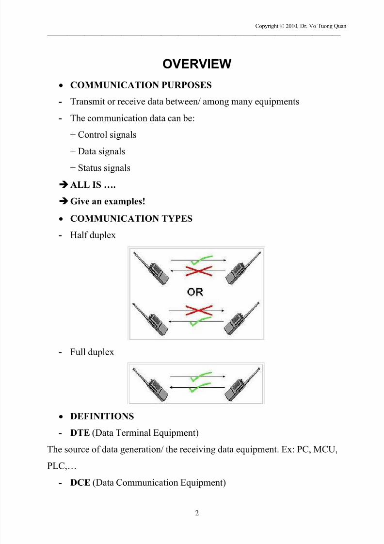
COMMUNICATION TYPES
- Half duplex
- Full duplex
DEFINITIONS
- DTE (Data Terminal Equipment)
The source of data generation/ the receiving data equipment. Ex: PC, MCU,
PLC,…
- DCE (Data Communication Equipment)

7/24/2019 PC Interfacing Lecture - 09-2013
http://slidepdf.com/reader/full/pc-interfacing-lecture-09-2013 3/36
Copyright © 2010, Dr. Vo Tuong Quan
_______________________________________________________________________________________________________
3
The intermediate equipment. Ex: Modem, Switch, Router,…
7/24/2019 PC Interfacing Lecture - 09-2013
http://slidepdf.com/reader/full/pc-interfacing-lecture-09-2013 4/36
Copyright © 2010, Dr. Vo Tuong Quan
_______________________________________________________________________________________________________
4
PROGRAMMABLE PERIPHERAL INTERFACE
8255
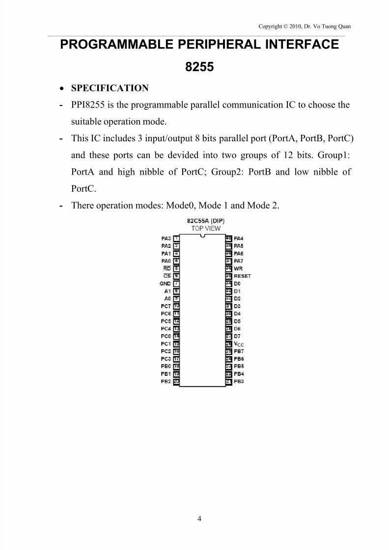
SPECIFICATION
- PPI8255 is the programmable parallel communication IC to choose the
suitable operation mode.
- This IC includes 3 input/output 8 bits parallel port (PortA, PortB, PortC)
and these ports can be devided into two groups of 12 bits. Group1:
PortA and high nibble of PortC; Group2: PortB and low nibble of
PortC.- There operation modes: Mode0, Mode 1 and Mode 2.

7/24/2019 PC Interfacing Lecture - 09-2013
http://slidepdf.com/reader/full/pc-interfacing-lecture-09-2013 5/36
Copyright © 2010, Dr. Vo Tuong Quan
_______________________________________________________________________________________________________
5
Function diagram
Data Bus Buffer
- Include 8 data lines, 3 status mode, 2 directions, connect directly to
system bus.
- The direction of data bus buffer is controlled by the Read/Write
Control Logic.
- Data bus buffer is the communication port between 8255 and CPU
(Central Processing Unit) or MCU (Micro Controller Unit) including
data and control word.
Read/Write Control Logic
- Receive control signals and address from system to control operation
mode of 8255.
- 0CS : 8255 run.
- RESET: Let the 8255 to the initial state.
- 01, A A : Choose the ports and control word of 8255.

7/24/2019 PC Interfacing Lecture - 09-2013
http://slidepdf.com/reader/full/pc-interfacing-lecture-09-2013 6/36
Copyright © 2010, Dr. Vo Tuong Quan
_______________________________________________________________________________________________________
6
- WR RD, : input or output mode.
- The operation mode of 8255
Operations
- PortA: Operate in Mode 0, 1, 2
- PortB: Operate in Mode 0, 1
- PortC: Operate in Mode 0 and PortC is used as the control signals for
PortA and PortB in operation mode 1.

7/24/2019 PC Interfacing Lecture - 09-2013
http://slidepdf.com/reader/full/pc-interfacing-lecture-09-2013 7/36
Copyright © 2010, Dr. Vo Tuong Quan
_______________________________________________________________________________________________________
7
INITIAL STATE (Reset)
- When reset, three ports of 8255 are set as input port at mode 0.
- To define the operation mode of 8255, we have to set the control word
with the suitable value.Control Word
- This control word will set the direction of ports (input/output) or
operation mode.
- Control word (8 bits) is save in the Control Word Register.
Ex: We choose the operation mode for 8255 like this:
Port A: Input, mode 1; Port B: Output, mode 0, Port C high : output, Port
C low : Input.
The value of CW : 10110001b => B1h
7/24/2019 PC Interfacing Lecture - 09-2013
http://slidepdf.com/reader/full/pc-interfacing-lecture-09-2013 8/36
Copyright © 2010, Dr. Vo Tuong Quan
_______________________________________________________________________________________________________
8
Outport(dia chi, gia tri)
- C, VC: outportb(0x37B, 0xB1);
- VB: outport(&h37B, &hB1)
A = input(&h37A); The mode bit set/reset of PortC
- Use to set or clear one specific bit of Port C.
- Normally use in the control mode
- The bit set reset of Port C is controlled by CW.
- Specification for CW:
Bit 7: 0
Bit: 6, 5, 4: X
Bit 3 , 2, 1: Choose bit (000 – bit 0 to 111 – bit 7)
Bit 0: = 0: Clear
= 1: Set
Ex: 0 0 0 0 0 1 1 0 Control Word Reg
Outport(&h37B, &h07) set bit 3 of Port C
Outport(&h37B, &h06) clear bit 3 of Port C
The control word of this case is also output to the control word address of
8255.
Note: The bit set/reset mode of port C does not effect to the normal operation
mode of 8255 was set before.
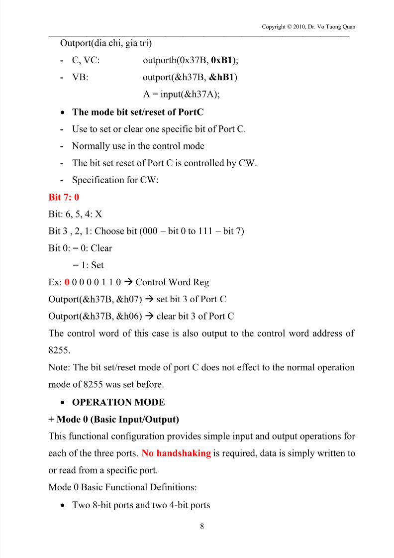
OPERATION MODE
+ Mode 0 (Basic Input/Output)
This functional configuration provides simple input and output operations for
each of the three ports. No handshaking is required, data is simply written to
or read from a specific port.
Mode 0 Basic Functional Definitions:
Two 8-bit ports and two 4-bit ports
7/24/2019 PC Interfacing Lecture - 09-2013
http://slidepdf.com/reader/full/pc-interfacing-lecture-09-2013 9/36
Copyright © 2010, Dr. Vo Tuong Quan
_______________________________________________________________________________________________________
9
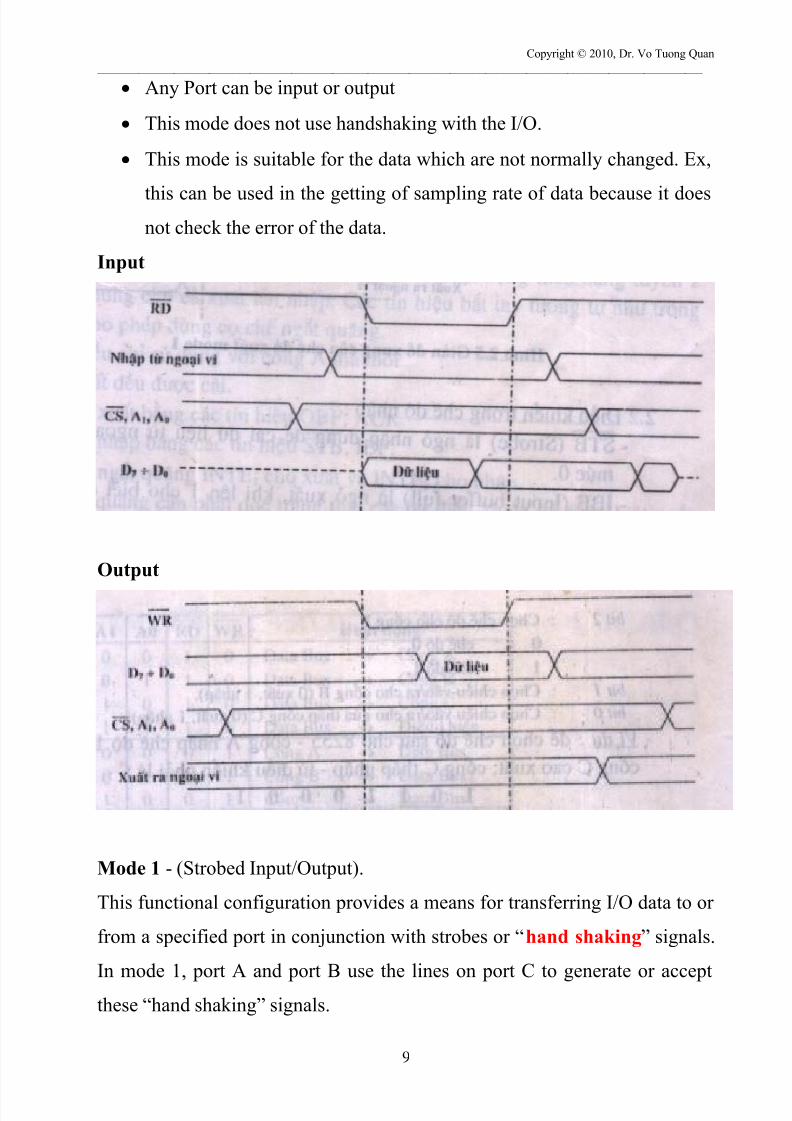
Any Port can be input or output
This mode does not use handshaking with the I/O.
This mode is suitable for the data which are not normally changed. Ex,
this can be used in the getting of sampling rate of data because it does
not check the error of the data.
Input
Output
Mode 1 - (Strobed Input/Output).
This functional configuration provides a means for transferring I/O data to or
from a specified port in conjunction with strobes or “hand shaking” signals.
In mode 1, port A and port B use the lines on port C to generate or accept
these “hand shaking” signals.
7/24/2019 PC Interfacing Lecture - 09-2013
http://slidepdf.com/reader/full/pc-interfacing-lecture-09-2013 10/36
Copyright © 2010, Dr. Vo Tuong Quan
_______________________________________________________________________________________________________
10
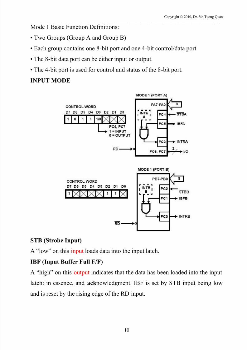
Mode 1 Basic Function Definitions:
• Two Groups (Group A and Group B)
• Each group contains one 8-bit port and one 4-bit control/data port
• The 8-bit data port can be either input or output.• The 4-bit port is used for control and status of the 8-bit port.
INPUT MODE
STB (Strobe Input)
A “low” on this input loads data into the input latch.
IBF (Input Buffer Full F/F)
A “high” on this output indicates that the data has been loaded into the input
latch: in essence, and ack nowledgment. IBF is set by STB input being low
and is reset by the rising edge of the RD input.
7/24/2019 PC Interfacing Lecture - 09-2013
http://slidepdf.com/reader/full/pc-interfacing-lecture-09-2013 11/36
Copyright © 2010, Dr. Vo Tuong Quan
_______________________________________________________________________________________________________
11
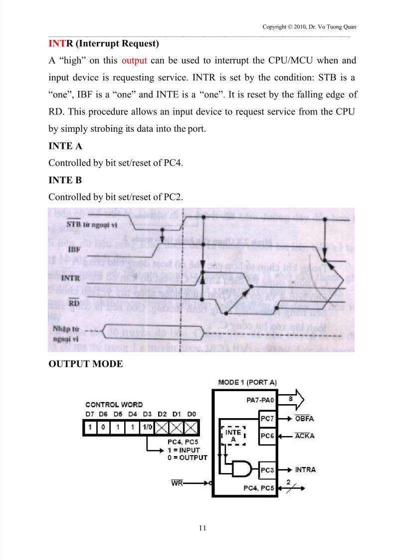
INTR (Interrupt Request)
A “high” on this output can be used to interrupt the CPU/MCU when and
input device is requesting service. INTR is set by the condition: STB is a
“one”, IBF is a “one” and INTE is a “one”. It is reset by the falling edge ofRD. This procedure allows an input device to request service from the CPU
by simply strobing its data into the port.
INTE A
Controlled by bit set/reset of PC4.
INTE B
Controlled by bit set/reset of PC2.
OUTPUT MODE

7/24/2019 PC Interfacing Lecture - 09-2013
http://slidepdf.com/reader/full/pc-interfacing-lecture-09-2013 12/36
Copyright © 2010, Dr. Vo Tuong Quan
_______________________________________________________________________________________________________
12
OBF – (Output Buffer Full). The OBF output will go “low” to indicate that
the CPU has written data out to be specified port.
Data is guaranteed valid at the rising edge of OBF, The OBF will be set by
the rising edge of the WR input and reset by ACK input being low.
ACK – (Acknowledge Input). A “low” on this input informs the 82C55 that
the data from Port A or Port B is ready to be accepted. In essence, a response
from the peripheral device indicating that it is ready to accept data.INTR - (Interrupt Request). A “high” on this output can be used to interrupt
the CPU when an output device has accepted data transmitted by the CPU.
INTR is set when ACK is a “one”, OBF is a “one” and INTE is a “one”. It is
reset by the falling edge of WR.
7/24/2019 PC Interfacing Lecture - 09-2013
http://slidepdf.com/reader/full/pc-interfacing-lecture-09-2013 13/36
Copyright © 2010, Dr. Vo Tuong Quan
_______________________________________________________________________________________________________
13
Mode 2 (Strobed Bi-Directional Bus I/O) – Self research
Ex: Using 8255 DLL// FILE: 8255.cpp#include <stdio.h>#include <conio.h> // contains Visual C++'s inp and outfunctions// ------------------------------------------------------// FUNC: Out8255// DESC: uses Microsoft's Visual C++ _outp() function// to output a PortData to PortAddress// ------------------------------------------------------short _stdcall Out8255( int PortAddress, int PortData ){short Dummy; Need Dummy since _outp officiall// back to VB Dummy = (short)(_outp( PortAddress, PortData ));return(Dummy);}; // end of Out8255// ----------------------------------------------------// FUNC: In8255// DESC: uses Microsoft's Visual C++ _inp() function// to read PortAddress// ----------------------------------------------------short _stdcall In8255( int PortAddress ){short PortData;in Win32 C++// use (short) to force returning 16- PortData = (short)(_inp( PortAddress ));return( PortData );}; /* end of In8255 */
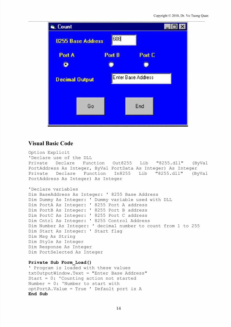
Ex: Count from zero to 255 then light up Led
7/24/2019 PC Interfacing Lecture - 09-2013
http://slidepdf.com/reader/full/pc-interfacing-lecture-09-2013 14/36
Copyright © 2010, Dr. Vo Tuong Quan
_______________________________________________________________________________________________________
14
Visual Basic Code
Option Explicit'Declare use of the DLLPrivate Declare Function Out8255 Lib "8255.dll" (ByValPortAddress As Integer, ByVal PortData As Integer) As Integer
Private Declare Function In8255 Lib "8255.dll" (ByValPortAddress As Integer) As Integer
'Declare variablesDim BaseAddress As Integer: ' 8255 Base AddressDim Dummy As Integer: ' Dummy variable used with DLLDim PortA As Integer: ' 8255 Port A addressDim PortB As Integer: ' 8255 Port B addressDim PortC As Integer: ' 8255 Port C addressDim Cntrl As Integer: ' 8255 Control AddressDim Number As Integer: ' decimal number to count from 1 to 255Dim Start As Integer: ' Start flagDim Msg As StringDim Style As IntegerDim Response As IntegerDim PortSelected As Integer
Private Sub Form_Load()' Program is loaded with these valuestxtOutputWindow.Text = "Enter Base Address"Start = 0: 'Counting action not startedNumber = 0: 'Number to start withoptPortA.Value = True ' Default port is AEnd Sub
7/24/2019 PC Interfacing Lecture - 09-2013
http://slidepdf.com/reader/full/pc-interfacing-lecture-09-2013 15/36
Copyright © 2010, Dr. Vo Tuong Quan
_______________________________________________________________________________________________________
15
Private Sub cmdGo_Click()If Start = 0 Then' user clicked GO button first timeIf txt8255Address.Text = "" Then' Base address was not defined
Msg = "Enter a Base Address! e.g. 608" ' Define message.Style = vbOK + vbExclamation ' Define buttons.Response = MsgBox(Msg, Style)Exit SubEnd IfStart = 1: ' Go button enabled; start countingcmdGo.Caption = "Pause"' Assign values for all addressesBaseAddress = Val(txt8255Address.Text)PortA = BaseAddressPortB = BaseAddress + 1PortC = BaseAddress + 2Cntrl = BaseAddress + 3' determine which port to output to' default is Port AIf optPortA.Value = True ThenPortSelected = PortAPrint PortSelectedEnd IfIf optPortB.Value = True ThenPortSelected = PortBPrint PortSelectedEnd IfIf optPortC.Value = True ThenPortSelected = PortCPrint PortSelectedEnd If' configure all ports for outputDummy = Out8255(Cntrl, 128)' initialize all Ports to 0Dummy = Out8255(PortA, 0)Dummy = Out8255(PortB, 0)Dummy = Out8255(PortC, 0)ElseStart = 0: ' user clicked GO button againcmdGo.Caption = "Go!"End IfEnd Sub
Private Sub cmdEnd_Click()Beep'txtOutputWindow.Text = "Stopped"Dummy = Out8255(PortA, 0)
Dummy = Out8255(PortB, 0)Dummy = Out8255(PortC, 0)' quit programEnd
7/24/2019 PC Interfacing Lecture - 09-2013
http://slidepdf.com/reader/full/pc-interfacing-lecture-09-2013 16/36
Copyright © 2010, Dr. Vo Tuong Quan
_______________________________________________________________________________________________________
16
End Sub
Private Sub tmrTimer_Timer()If Start = 1 ThenNumber = Number + 1
Dummy = Out8255(PortSelected, Number)txtOutputWindow.Text = "Number = " + Str(Number)If Number = 255 ThenBeeptxtOutputWindow.Text = "Finished"Dummy = Out8255(PortSelected, 0)Start = 0Number = 0cmdGo.Caption = "Go!"Exit SubEnd If
ElseExit SubEnd IfEnd Sub
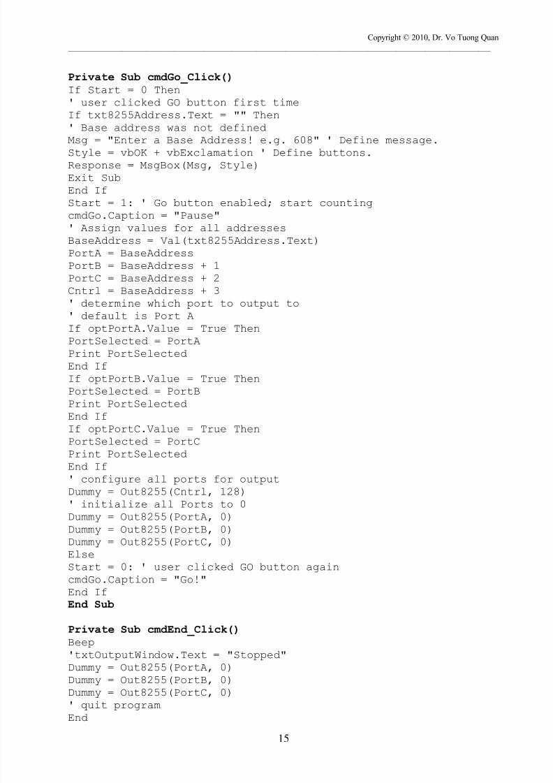
Ex: Print out the decimal equivalent of the 8 position Dip switch
Option Explicit'Declare use of the DLLPrivate Declare Function Out8255 Lib "8255.dll" (ByValPortAddress As Integer, ByVal PortData As Integer) As IntegerPrivate Declare Function In8255 Lib "8255.dll" (ByValPortAddress As Integer) As Integer'Declare variablesDim BaseAddress As Integer: ' 8255 Base Address

7/24/2019 PC Interfacing Lecture - 09-2013
http://slidepdf.com/reader/full/pc-interfacing-lecture-09-2013 17/36
Copyright © 2010, Dr. Vo Tuong Quan
_______________________________________________________________________________________________________
17
Dim Dummy As Integer: ' Dummy variable used with DLLDim PortA As Integer: ' 8255 Port A addressDim PortB As Integer: ' 8255 Port B addressDim PortC As Integer: ' 8255 Port C addressDim Cntrl As Integer: ' 8255 Control AddressDim PortValue As Integer: ' decimal value read at port
Dim PortValue As Integer: ' decimal value read at portDim Start As Integer: ' Start flagDim Msg As StringDim Style As IntegerDim Response As IntegerDim PortSelected As Integer
Private Sub cmdEnd_Click()Beep
'txtOutputWindow.Text = "Stopped"' quit programEndEnd Sub
Private Sub cmdGo_Click()If Start = 0 Then' user clicked GO button first timeIf txt8255Address.Text = "" Then' Base address was not definedMsg = "Enter a Base Address! e.g. 608" ' Define message.
Style = vbOK + vbExclamation ' Define buttons.Response = MsgBox(Msg, Style)Exit SubEnd IfStart = 1: ' Go button enabled; start countingcmdGo.Caption = "Pause"' Assign values for all addressesBaseAddress = Val(txt8255Address.Text)PortA = BaseAddressPortB = BaseAddress + 1PortC = BaseAddress + 2
Cntrl = BaseAddress + 3' determine which port to output to' default is Port AIf optPortA.Value = True ThenPortSelected = PortAEnd IfIf optPortB.Value = True ThenPortSelected = PortBEnd IfIf optPortC.Value = True ThenPortSelected = PortC
End If' configure all ports for inputDummy = Out8255(Cntrl, 155)
7/24/2019 PC Interfacing Lecture - 09-2013
http://slidepdf.com/reader/full/pc-interfacing-lecture-09-2013 18/36
Copyright © 2010, Dr. Vo Tuong Quan
_______________________________________________________________________________________________________
18
' initialize all Ports to 0ElseStart = 0: ' user clicked GO button againcmdGo.Caption = "Go!"End IfEnd Sub
Private Sub Form_Load()' Program is loaded with these valuestxtOutputWindow.Text = "Enter Base Address"Start = 0: 'Counting action not startedoptPortA.Value = True ' Default port is AEnd SubPrivate Sub tmrTimer_Timer()If Start = 1 ThenPortValue = In8255(PortSelected)
txtOutputWindow.Text = "Value = " + Str(PortValue)End IfEnd Sub
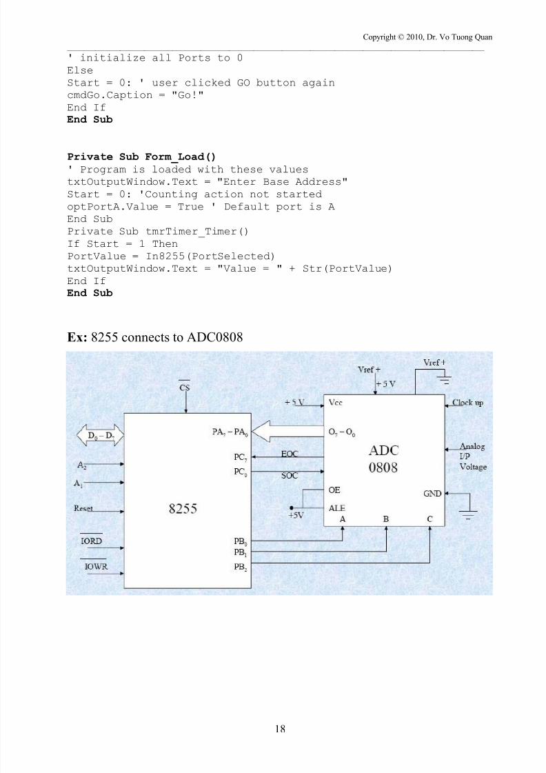
Ex: 8255 connects to ADC0808
7/24/2019 PC Interfacing Lecture - 09-2013
http://slidepdf.com/reader/full/pc-interfacing-lecture-09-2013 19/36
Copyright © 2010, Dr. Vo Tuong Quan
_______________________________________________________________________________________________________
19
7/24/2019 PC Interfacing Lecture - 09-2013
http://slidepdf.com/reader/full/pc-interfacing-lecture-09-2013 20/36
Copyright © 2010, Dr. Vo Tuong Quan
_______________________________________________________________________________________________________
20
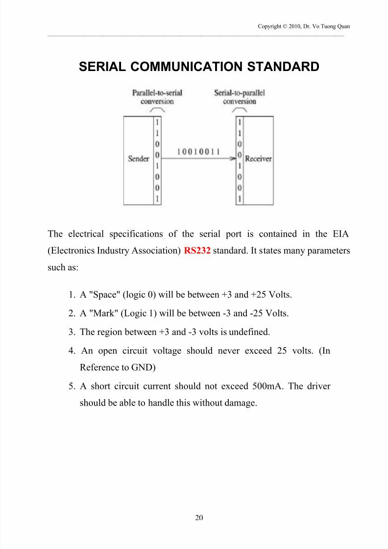
SERIAL COMMUNICATION STANDARD
The electrical specifications of the serial port is contained in the EIA
(Electronics Industry Association) RS232 standard. It states many parameters
such as:
1. A "Space" (logic 0) will be between +3 and +25 Volts.
2. A "Mark" (Logic 1) will be between -3 and -25 Volts.
3. The region between +3 and -3 volts is undefined.
4. An open circuit voltage should never exceed 25 volts. (In
Reference to GND)
5. A short circuit current should not exceed 500mA. The driver
should be able to handle this without damage.

7/24/2019 PC Interfacing Lecture - 09-2013
http://slidepdf.com/reader/full/pc-interfacing-lecture-09-2013 21/36
Copyright © 2010, Dr. Vo Tuong Quan
_______________________________________________________________________________________________________
21
The com port in a PC has 9 female pins.
Pin No Abbreviation Full Name
Pin 2 RD Transmit Data
Pin 3 TD Receive Data
Pin 7 RTS Request To Send
Pin 8 CTS Clear To Send
Pin 6 DSR Data Set Ready
Pin 5 SG Signal Ground
Pin 1 CD Carrier Detect
Pin 4 DTRData Terminal
Ready
Pin 9 RI Ring Indicator
There are two kinds of serial communication
The speed of transmission is called Baud (bit/s)

7/24/2019 PC Interfacing Lecture - 09-2013
http://slidepdf.com/reader/full/pc-interfacing-lecture-09-2013 22/36
Copyright © 2010, Dr. Vo Tuong Quan
_______________________________________________________________________________________________________
22
The width of bit also expresses the speed of communication. Ex, the
transmission data has the width of bit is 20ms, this means that it can be
transmit 1/20ms = 50 bit in 1 second. Then, it can be said that the
transmission speed is 50 bit per second or the baud rate is 50bps (bit persecond). Baud (Baud is number of bits transmitted/sec, including start, stop,
data and parity).
Some typical Baud of serial communications: 300, 600, 1200, 2400, 4800,
9600, 19200,….., 56000, 115200,….
Ex: Null Modem
1. SYNCHRONOUS COMMUNICATION
Sender and receiver must synchronize.
Block of data can be sent.
More efficient.
Expensive
Synchronous transmit/receive diagram
7/24/2019 PC Interfacing Lecture - 09-2013
http://slidepdf.com/reader/full/pc-interfacing-lecture-09-2013 23/36
Copyright © 2010, Dr. Vo Tuong Quan
_______________________________________________________________________________________________________
23
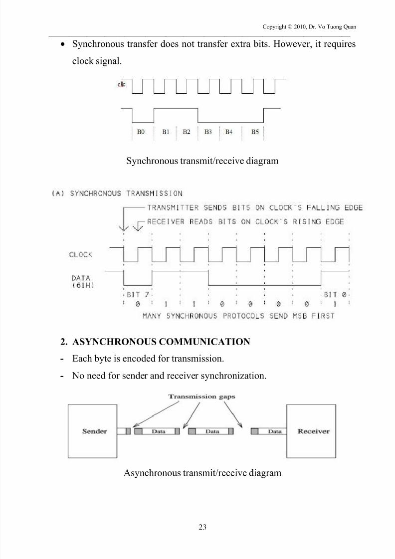
Synchronous transfer does not transfer extra bits. However, it requires
clock signal.
Synchronous transmit/receive diagram
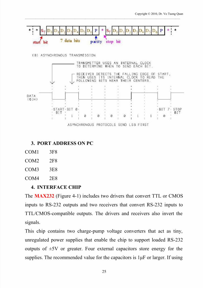
2. ASYNCHRONOUS COMMUNICATION
- Each byte is encoded for transmission.
- No need for sender and receiver synchronization.
Asynchronous transmit/receive diagram

7/24/2019 PC Interfacing Lecture - 09-2013
http://slidepdf.com/reader/full/pc-interfacing-lecture-09-2013 24/36
Copyright © 2010, Dr. Vo Tuong Quan
_______________________________________________________________________________________________________
24
Asynchronous transfer does not require clock signal. However, it
transfers extra bits (start bits and stop bits, parity bit) during data
communication.
-10 V Mark
+10 V Space
Asynchronous data transfer diagram
In the RS232 standard, logic 1 is named Mark (-10V) and logic 0 is
named Space (+10V). When not active, the transmission line is in the state of Mark.
When starting transmission, the Start bit is transmitted first, then 8 data
bit are followed (The LSB bit is transmit first then the MSB bit is
transmitted in the end).
7/24/2019 PC Interfacing Lecture - 09-2013
http://slidepdf.com/reader/full/pc-interfacing-lecture-09-2013 25/36
Copyright © 2010, Dr. Vo Tuong Quan
_______________________________________________________________________________________________________
25
3. PORT ADDRESS ON PC
COM1 3F8
COM2 2F8
COM3 3E8
COM4 2E8
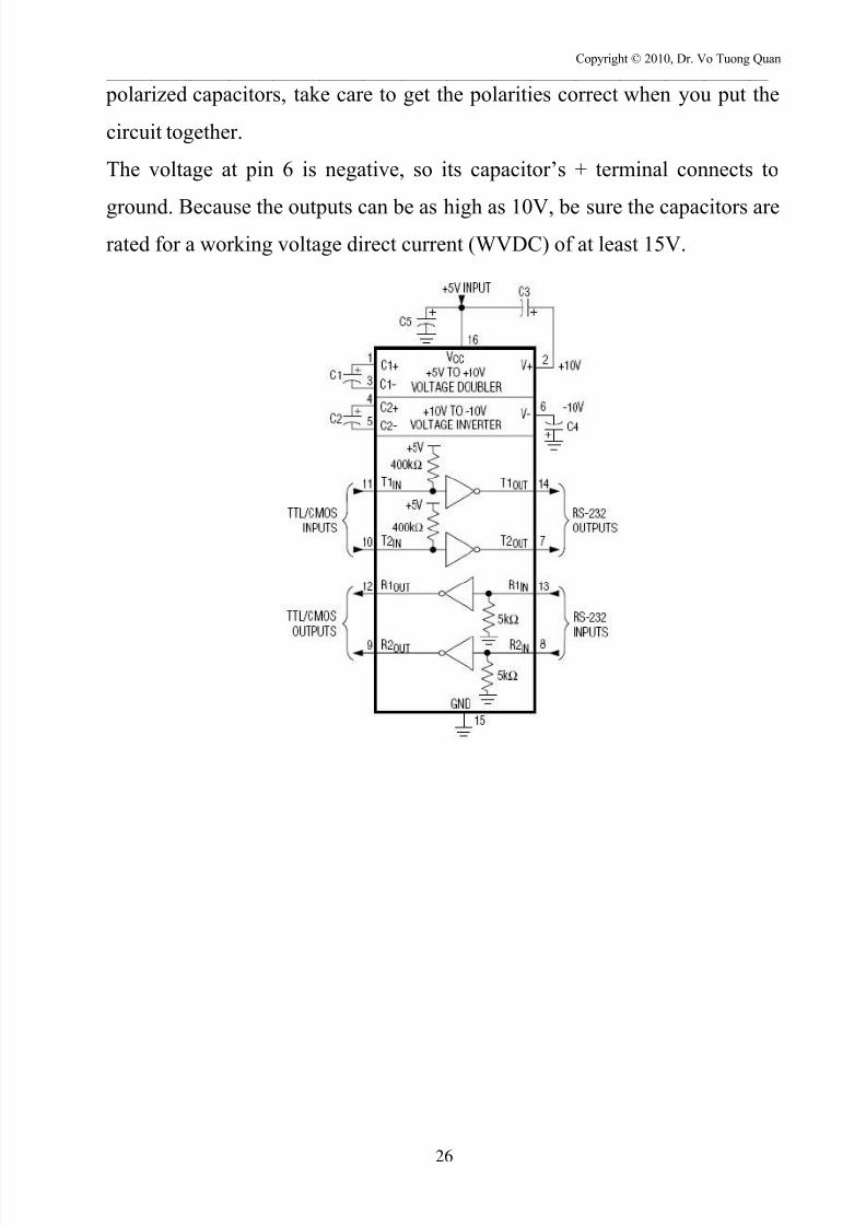
4. INTERFACE CHIP
The MAX232 (Figure 4-1) includes two drivers that convert TTL or CMOS
inputs to RS-232 outputs and two receivers that convert RS-232 inputs to
TTL/CMOS-compatible outputs. The drivers and receivers also invert the
signals.
This chip contains two charge-pump voltage converters that act as tiny,
unregulated power supplies that enable the chip to support loaded RS-232
outputs of ±5V or greater. Four external capacitors store energy for the
supplies. The recommended value for the capacitors is 1μF or larger. If using
7/24/2019 PC Interfacing Lecture - 09-2013
http://slidepdf.com/reader/full/pc-interfacing-lecture-09-2013 26/36
Copyright © 2010, Dr. Vo Tuong Quan
_______________________________________________________________________________________________________
26
polarized capacitors, take care to get the polarities correct when you put the
circuit together.
The voltage at pin 6 is negative, so its capacitor’s + terminal connects to
ground. Because the outputs can be as high as 10V, be sure the capacitors arerated for a working voltage direct current (WVDC) of at least 15V.

7/24/2019 PC Interfacing Lecture - 09-2013
http://slidepdf.com/reader/full/pc-interfacing-lecture-09-2013 27/36
Copyright © 2010, Dr. Vo Tuong Quan
_______________________________________________________________________________________________________
27
5. PROGRAMMING SERIAL COMMUNICATION USING PC
The controller of the serial communication on PC is called UART (Universal
Asynchronous Receiver Transmitter). Some typical UART controllers are:
8250, 8250A, 16550, 16650, 16750,…
In these UART controller, we just focus on some registers supply for
programming PC.
7/24/2019 PC Interfacing Lecture - 09-2013
http://slidepdf.com/reader/full/pc-interfacing-lecture-09-2013 28/36
Copyright © 2010, Dr. Vo Tuong Quan
_______________________________________________________________________________________________________
28
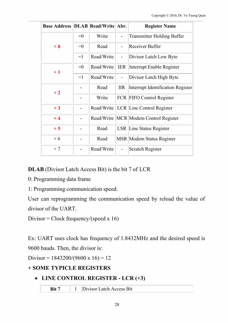
Base Address DLAB Read/Write Abr. Register Name
+ 0
=0 Write - Transmitter Holding Buffer
=0 Read - Receiver Buffer
=1 Read/Write - Divisor Latch Low Byte
+ 1=0 Read/Write IER Interrupt Enable Register
=1 Read/Write - Divisor Latch High Byte
+ 2- Read IIR Interrupt Identification Register
- Write FCR FIFO Control Register
+ 3 - Read/Write LCR Line Control Register
+ 4 - Read/Write MCR Modem Control Register
+ 5 - Read LSR Line Status Register
+ 6 - Read MSR Modem Status Register
+ 7 - Read/Write - Scratch Register
DLAB (Divisor Latch Access Bit) is the bit 7 of LCR
0: Programming data frame
1: Programming communication speed.
User can reprogramming the communication speed by reload the value of
divisor of the UART.
Divisor = Clock frequency/(speed x 16)
Ex: UART uses clock has frequency of 1.8432MHz and the desired speed is
9600 bauds. Then, the divisor is:
Divisor = 1843200/(9600 x 16) = 12
+ SOME TYPICLE REGISTERS
LINE CONTROL REGISTER - LCR (+3)
Bit 7 1 Divisor Latch Access Bit

7/24/2019 PC Interfacing Lecture - 09-2013
http://slidepdf.com/reader/full/pc-interfacing-lecture-09-2013 29/36
Copyright © 2010, Dr. Vo Tuong Quan
_______________________________________________________________________________________________________
29
0Access to Receiver buffer, Transmitter buffer &
Interrupt Enable Register
Bit 6 Set Break Enable
Bits 3, 4 And
5
Bit
5
Bit
4
Bit
3Parity Select
X X 0 No Parity
0 0 1 Odd Parity
0 1 1 Even Parity
Bit 2 Length of Stop Bit
0 One Stop Bit
12 Stop bits for words of length 6,7 or 8 bits or 1.5 Stop
Bits for Word lengths of 5 bits.
Bits 0 And 1 Bit
1
Bit
0 Word Length
0 0 5 Bits
0 1 6 Bits
1 0 7 Bits
1 1 8 Bits
Opencom(‘Com4’, 9600, 8, N, 1) TX
Opencom(‘Com7’, 9600, 8, N, 1) RX
E: even
O: odd
PARITY
A parity bit is a bit that is added to ensure that the number of bits with the
value one in a set of bits is even or odd. Parity bits are used as the simplest
form of error detecting code.
There are two variants of parity bits: even parity bit and odd parity bit.
When using even parity, the parity bit is set to 1 if the number of ones in a
given set of bits (not including the parity bit) is odd, making the entire set of
bits (including the parity bit) even. When using odd parity, the parity bit is set
to 1 if the number of ones in a given set of bits (not including the parity bit) is
even, keeping the entire set of bits (including the parity bit) odd.

7/24/2019 PC Interfacing Lecture - 09-2013
http://slidepdf.com/reader/full/pc-interfacing-lecture-09-2013 30/36
Copyright © 2010, Dr. Vo Tuong Quan
_______________________________________________________________________________________________________
30
However, parity has the advantage that it uses only a single bit and requires
only a number of XOR gates to generate.
If an odd number of bits (including the parity bit) are transmitted incorrectly,
the parity bit will be incorrect and thus indicates that an error occurred intransmission. The parity bit is only suitable for detecting errors; it cannot
correct any errors, as there is no way to determine which particular bit is
corrupted. The data must be discarded entirely, and re-transmitted from
scratch.
Ex: The parity bit can be computed as follows, assuming we are sending a
simple 4-bit value 1001 with the parity bit following on the right, and with ^
denoting an XOR gate:
Transmission sent using even parity:
A wants to transmit: 1001
A adds parity bit and sends: 10010
A computes parity bit value: 1^0^0^1^0 = 0
B receives: 10010
B computes parity: 1^0^0^1^0 = 0
B reports correct transmission after observing expected even result.
Transmission sent using odd parity:
A wants to transmit: 1001
A adds parity bit and sends: 10011
A computes parity bit value: 1^0^0^1^1 = 1
B receives: 10011
B computes overall parity: 1^0^0^1^1 = 1
B reports correct transmission after observing expected odd result.

7/24/2019 PC Interfacing Lecture - 09-2013
http://slidepdf.com/reader/full/pc-interfacing-lecture-09-2013 31/36
Copyright © 2010, Dr. Vo Tuong Quan
_______________________________________________________________________________________________________
31
Transmission sent using even parity:
A wants to transmit: 1001
A adds parity bit and sends: 10010
A computes parity bit value: 1^0^0^1^0 = 0*** ERROR CASE ***
B receives: 11010
B computes overall parity: 1^1^0^1^0 = 1
B reports incorrect transmission after observing unexpected odd result.
B calculates an odd overall parity indicating the bit error. Here's the same
example but now the parity bit itself gets corrupted:
A wants to transmit: 1001
A computes even parity value: 1^0^0^1 = 0
A sends: 10010
*** ERROR CASE ***
B receives: 10011
B computes overall parity: 1^0^0^1^1 = 1
B reports incorrect transmission after observing unexpected odd result.
Special case
A wants to transmit: 1001
A computes even parity value: 1^0^0^1 = 0
A sends: 10010
*** ERROR CASE***
B receives: 11011
B computes overall parity: 1^1^0^1^1 = 0
B reports correct transmission though actually incorrect.
If there are two bits error, parity can not check!
7/24/2019 PC Interfacing Lecture - 09-2013
http://slidepdf.com/reader/full/pc-interfacing-lecture-09-2013 32/36
Copyright © 2010, Dr. Vo Tuong Quan
_______________________________________________________________________________________________________
32
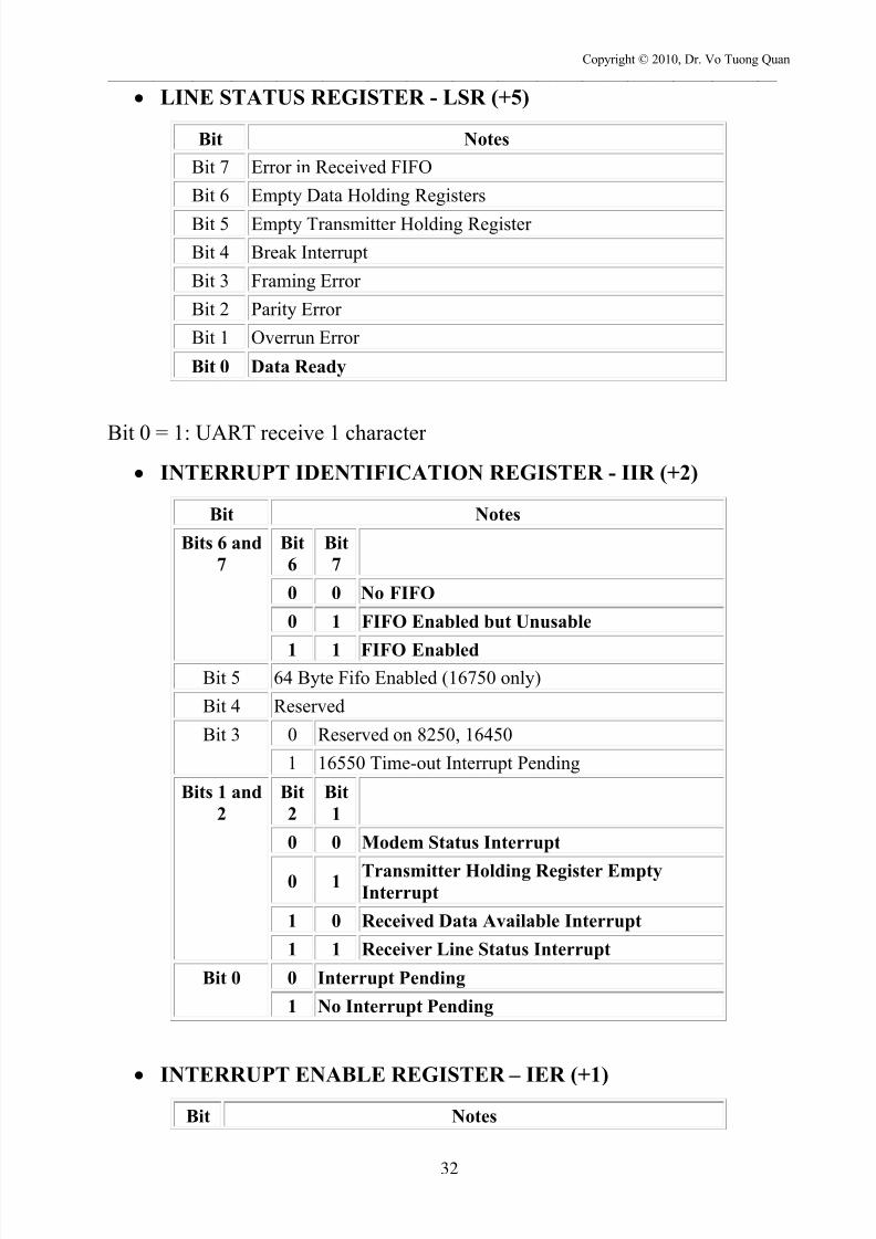
LINE STATUS REGISTER - LSR (+5)
Bit Notes
Bit 7 Error in Received FIFO
Bit 6 Empty Data Holding Registers
Bit 5 Empty Transmitter Holding Register
Bit 4 Break Interrupt
Bit 3 Framing Error
Bit 2 Parity Error
Bit 1 Overrun Error
Bit 0 Data Ready
Bit 0 = 1: UART receive 1 character
INTERRUPT IDENTIFICATION REGISTER - IIR (+2)
Bit Notes
Bits 6 and
7
Bit
6
Bit
7
0 0 No FIFO
0 1 FIFO Enabled but Unusable
1 1 FIFO EnabledBit 5 64 Byte Fifo Enabled (16750 only)
Bit 4 Reserved
Bit 3 0 Reserved on 8250, 16450
1 16550 Time-out Interrupt Pending
Bits 1 and
2
Bit
2
Bit
1
0 0 Modem Status Interrupt
0 1 Transmitter Holding Register EmptyInterrupt
1 0 Received Data Available Interrupt
1 1 Receiver Line Status Interrupt
Bit 0 0 Interrupt Pending
1 No Interrupt Pending
INTERRUPT ENABLE REGISTER – IER (+1)Bit Notes

7/24/2019 PC Interfacing Lecture - 09-2013
http://slidepdf.com/reader/full/pc-interfacing-lecture-09-2013 33/36
Copyright © 2010, Dr. Vo Tuong Quan
_______________________________________________________________________________________________________
33
Bit 7 Reserved
Bit 6 Reserved
Bit 5 Enables Low Power Mode (16750)
Bit 4 Enables Sleep Mode (16750)
Bit 3 Enable Modem Status InterruptBit 2 Enable Receiver Line Status Interrupt
Bit 1 Enable Transmitter Holding Register Empty Interrupt
Bit 0 Enable Received Data Available Interrupt
MODEM CONTROL REGISTER – MCR (+4)
Bit Notes
Bit 7 Reserved
Bit 6 Reserved
Bit 5 Autoflow Control Enabled (16750 only)
Bit 4 LoopBack Mode
Bit 3 Aux Output 2
Bit 2 Aux Output 1
Bit 1 Force Request to Send
Bit 0 Force Data Terminal Ready
7/24/2019 PC Interfacing Lecture - 09-2013
http://slidepdf.com/reader/full/pc-interfacing-lecture-09-2013 34/36
Copyright © 2010, Dr. Vo Tuong Quan
_______________________________________________________________________________________________________
34
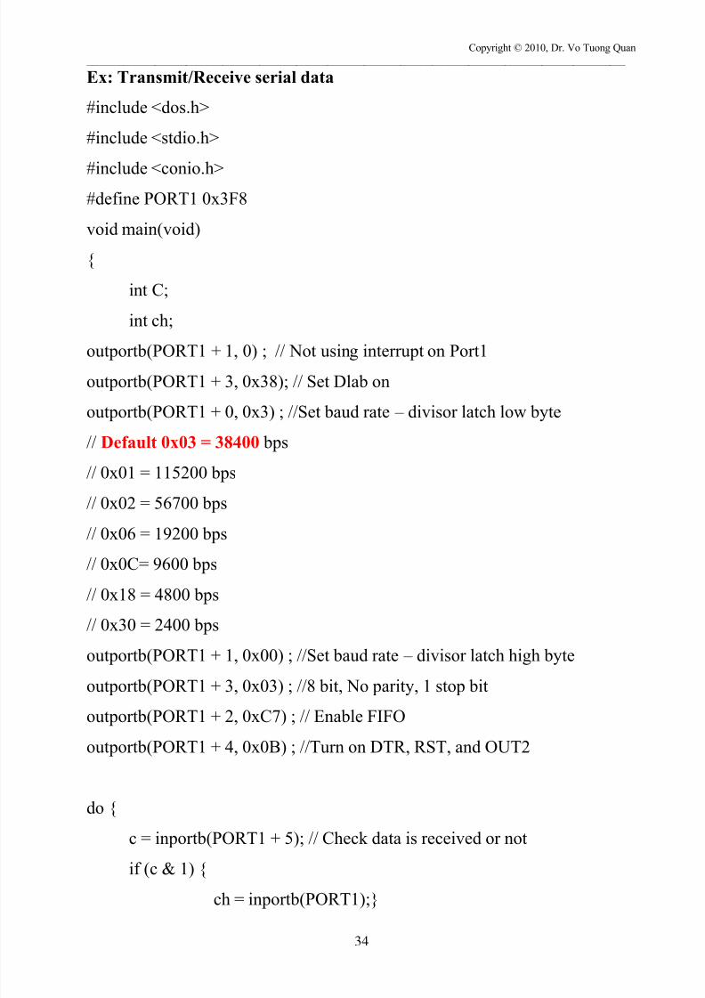
Ex: Transmit/Receive serial data
#include <dos.h>
#include <stdio.h>
#include <conio.h>#define PORT1 0x3F8
void main(void)
{
int C;
int ch;
outportb(PORT1 + 1, 0) ; // Not using interrupt on Port1
outportb(PORT1 + 3, 0x38); // Set Dlab on
outportb(PORT1 + 0, 0x3) ; //Set baud rate – divisor latch low byte
// Default 0x03 = 38400 bps
// 0x01 = 115200 bps
// 0x02 = 56700 bps
// 0x06 = 19200 bps
// 0x0C= 9600 bps
// 0x18 = 4800 bps
// 0x30 = 2400 bps
outportb(PORT1 + 1, 0x00) ; //Set baud rate – divisor latch high byte
outportb(PORT1 + 3, 0x03) ; //8 bit, No parity, 1 stop bit
outportb(PORT1 + 2, 0xC7) ; // Enable FIFO
outportb(PORT1 + 4, 0x0B) ; //Turn on DTR, RST, and OUT2
do {
c = inportb(PORT1 + 5); // Check data is received or not
if (c & 1) {ch = inportb(PORT1);}
7/24/2019 PC Interfacing Lecture - 09-2013
http://slidepdf.com/reader/full/pc-interfacing-lecture-09-2013 35/36
Copyright © 2010, Dr. Vo Tuong Quan
_______________________________________________________________________________________________________
35
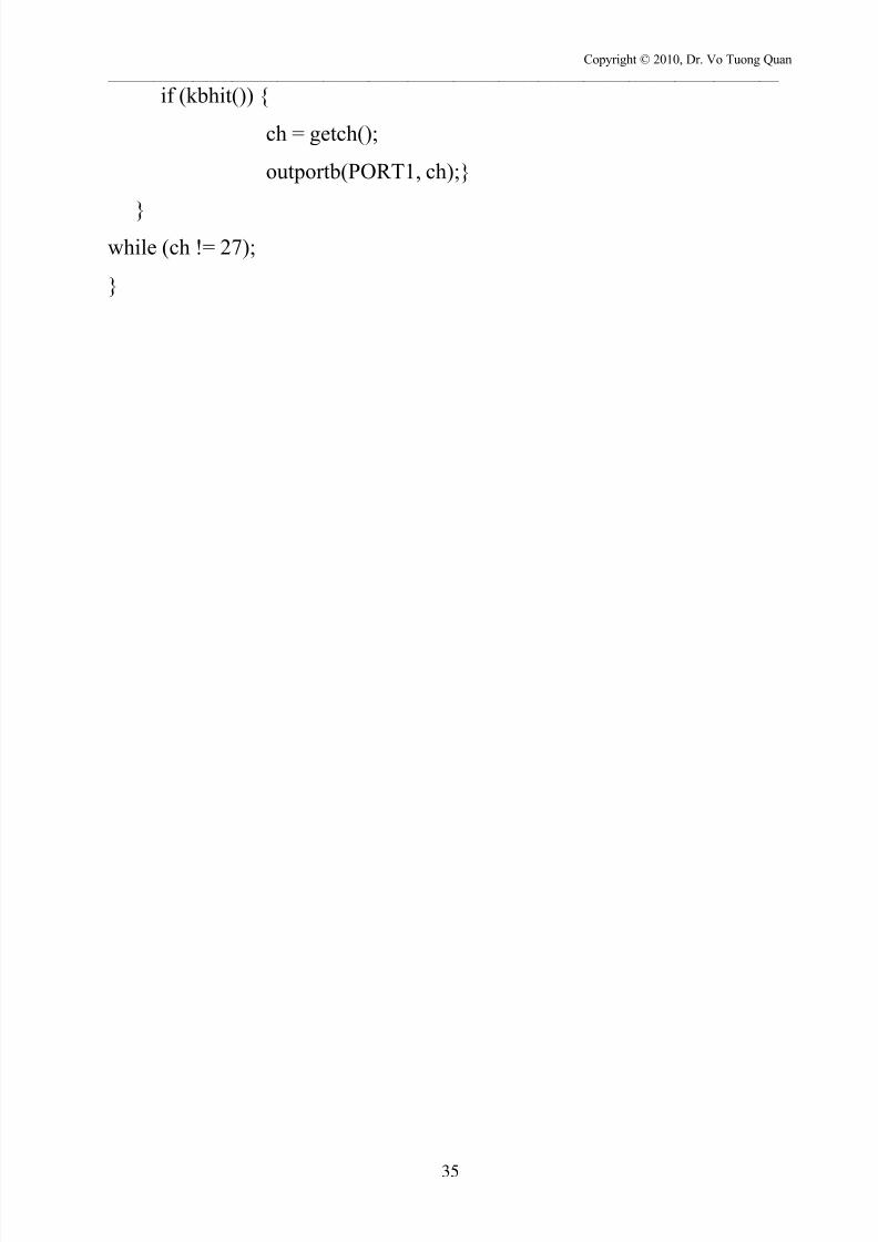
if (kbhit()) {
ch = getch();
outportb(PORT1, ch);}
}while (ch != 27);
}
7/24/2019 PC Interfacing Lecture - 09-2013
http://slidepdf.com/reader/full/pc-interfacing-lecture-09-2013 36/36
Copyright © 2010, Dr. Vo Tuong Quan
_______________________________________________________________________________________________________
EXERCISE:
Using COM Port control many actuators
Type