Embed Size (px)
Citation preview
PCC-450 REFERENCE BOOK
- 1 -
PCC-450REFERENCE BOOK
IMPORTANT NOTEBy using this software, you acknowledge that the Software is not intended for use in connection with anyhigh risk of personal injury or strict liability activity (including, without limitation to, air travel, spacetravel, fire fighting, police operations, power plant operation, military operations, rescue operations, hospi-tal and medical operations) and that Vertex Standard makes no warranty and shall have no liability in con-nection with any use of the Software in such situations.
All title and copyrights in and to the Software (including but not limited to any data, images, text, and othercomponents), and the accompanying printed materials, are owned by Vertex Standard. The Software isprotected by copyright laws and international treaty provisions, including U.S. federal criminal law. VertexStandard and YAESU are trademarks of Vertex Standard.
Vertex Standard expressly disclaims any warranty for the Software and Services. The Software and Ser-vices and any related documentation are provided “AS IS” without warranty of any kind, either express orimplied, including, without limitation, the implied warranties or merchantability, fitness for a particularpurpose, security, or noninfringement. The entire risk arising out of use or performance of the Software andthe Services remains with you.

PCC-450 REFERENCE BOOK
- 2 -
PCC-450 System Components ...................................... 3FT-450 and Computer Interconnections ........................ 3“PCC-450” Personal Computer Controller Window..... 3Opening/Closing the PCC-450 Controller Program ..... 4Data Connection ............................................................ 4Switching Power On/Off of the FT-450 ........................ 4AF Gain Control ............................................................ 4BAND Selection ............................................................ 5MODE Selection ........................................................... 5Frequency Navigation ................................................... 6Clarifier Operation ........................................................ 7Digital Voice Announcement ......................................... 7Audio Playback Feature ................................................ 7Voice Memory Feature .................................................. 8IPO (Intercept Point Optimization) &
ATT (Attenuator) ..................................................... 8RF Gain Control ............................................................ 9Noise Blanker Operation ............................................... 9AGC ............................................................................... 9CONTOUR Filter Operation ....................................... 10IF SHIFT Operation .................................................... 10WIDTH Operation ....................................................... 11NOTCH Operation ...................................................... 11
DNR (Digital Noise Reduction) Operation ................. 12DSP Microphone Equalizer ......................................... 12LOCK Feature ............................................................. 13Repeater Operation ...................................................... 13Beacon Feature ............................................................ 14CW Spotting ................................................................ 15TX/RX ......................................................................... 15Operation of Miscellaneous Knobs and Buttons ......... 16
[KEYER] Button ................................................... 16[A=B] Button ......................................................... 16[A/B] Button .......................................................... 16[TUNE] Button ...................................................... 16[F] Button .............................................................. 16[METER] Button ................................................... 17[VOICE/C.S] Button ............................................. 17[MW/V/M] Button .................................................. 18[HOME/RCL] Button ........................................... 18[VOX/STO] Button ............................................... 18[STEP/SPLIT] Button .......................................... 19[PMS/SCAN] Button ............................................ 19
Menu Operation ........................................................... 20Command Send ........................................................... 21Function Key Operation .............................................. 22
TABLE OF CONTENTS

PCC-450 REFERENCE BOOK
- 3 -
FT-450 AND COMPUTER INTERCONNECTIONS
“PCC-450” PERSONAL COMPUTER CONTROLLER WINDOW
PCC-450 SYSTEM COMPONENTSIBM® PC / compatible Computer with Microsoft® Windows® 2000, XP, or Vista30 MB of available Hard Disk space256 MB or more RAMRS-232C port1024 x 768 color display with 256-bit color support on the video cardRS-232C “Straight” Cable, DB9-pin Female to DB9-pin Female. (Or, USB to RS-232C Adapter Cable)
INPUTDC 13.8V 22A
ANT
GNDEXTSPKRCATLINEARTUNERDATA
COM
CAT
RS-232C “Straight” Cable

PCC-450 REFERENCE BOOK
- 4 -
OPENING/CLOSING THE PCC-450 CONTROLLER PROGRAMOPENING THE PCC-450 PROGRAMDouble click the left mouse button on the “PCC-450” icon orfile. The “Vertex Standard” logo will appear for three seconds;afterwards the “PCC-450” Personal Computer Controller Win-dow will open.
CLOSING THE PCC-450 PROGRAMTo close the “PCC-450” Personal Computer Controller:
Click the Close Button “ ” on the “PCC-450” Personal Com-puter Controller Window.Alternately, click the “Exit” item in the “File” menu on the“PCC-450” Personal Computer Controller Window.
DATA CONNECTIONTo enable computer control, click the left mouse button onthe [COM] button in the “PCC-450” Personal Computer Con-troller Window. The yellow indicator will glow.To disable computer control, click the left mouse button onthe [COM] button in the “PCC-450” Personal Computer Con-troller Window again. The yellow indicator will go out.
SWITCHING POWER ON/OFF OF THE FT-450To turn the transceiver “On” or “Off”: click the left mouse buttonin the [ON/OFF] button of the “PCC-450” Personal ComputerController Window.
AF GAIN CONTROLTo adjust the audio for a comfortable listening level, click theleft mouse button on the [AF GAIN] knob (the indication colorof “AF GAIN” will turn yellow), then turn the mouse scroll wheelor press the left/right mouse buttons to adjust AF gain.
“EXIT” parameter
“PCC-450” icon Close button
[COM] button
[ON/OFF] button
[AF GAIN] knob
PCC-450 REFERENCE BOOK
- 5 -
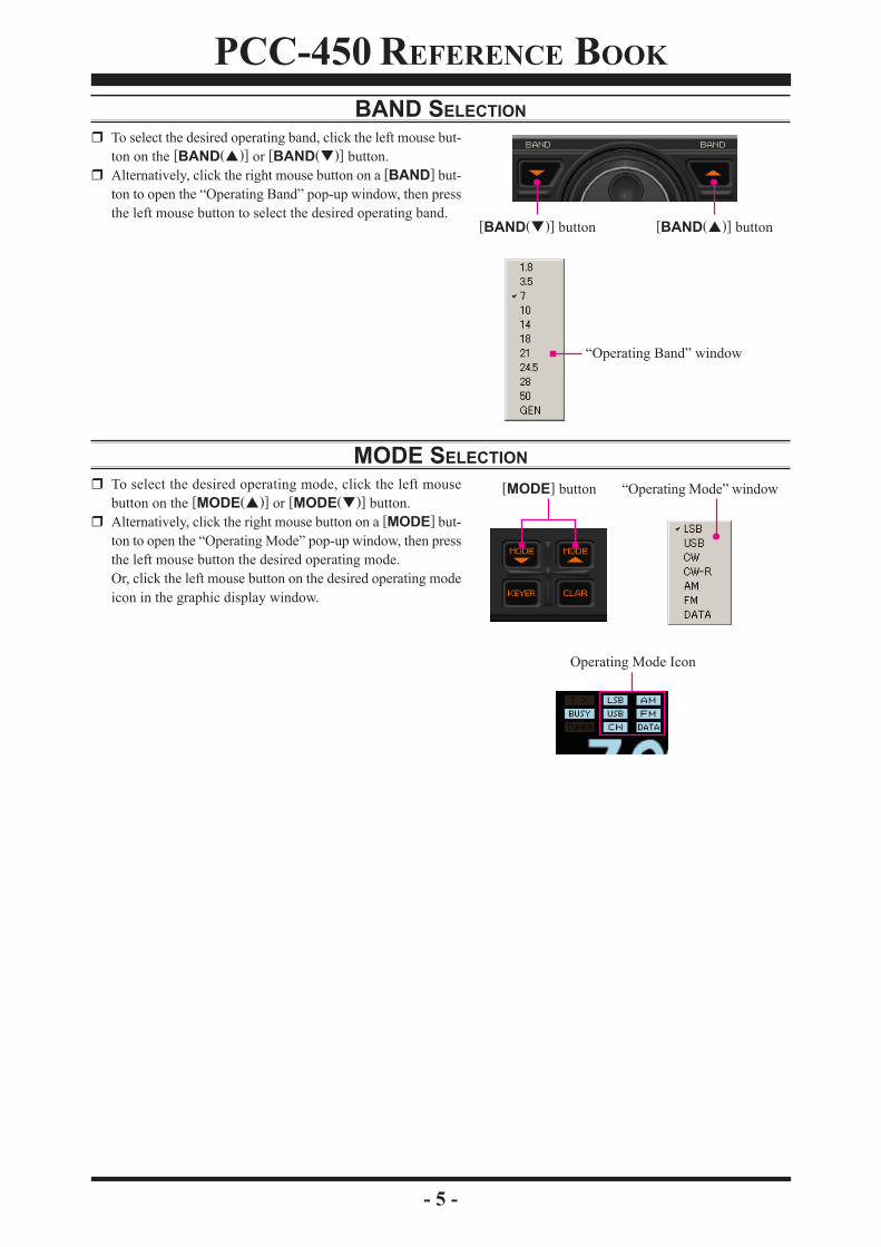
BAND SELECTIONTo select the desired operating band, click the left mouse but-ton on the [BAND( )] or [BAND( )] button.Alternatively, click the right mouse button on a [BAND] but-ton to open the “Operating Band” pop-up window, then pressthe left mouse button to select the desired operating band.
MODE SELECTIONTo select the desired operating mode, click the left mousebutton on the [MODE( )] or [MODE( )] button.Alternatively, click the right mouse button on a [MODE] but-ton to open the “Operating Mode” pop-up window, then pressthe left mouse button the desired operating mode.Or, click the left mouse button on the desired operating modeicon in the graphic display window.
“Operating Band” window
[BAND( )] button [BAND( )] button
“Operating Mode” window[MODE] button
Operating Mode Icon
PCC-450 REFERENCE BOOK
- 6 -
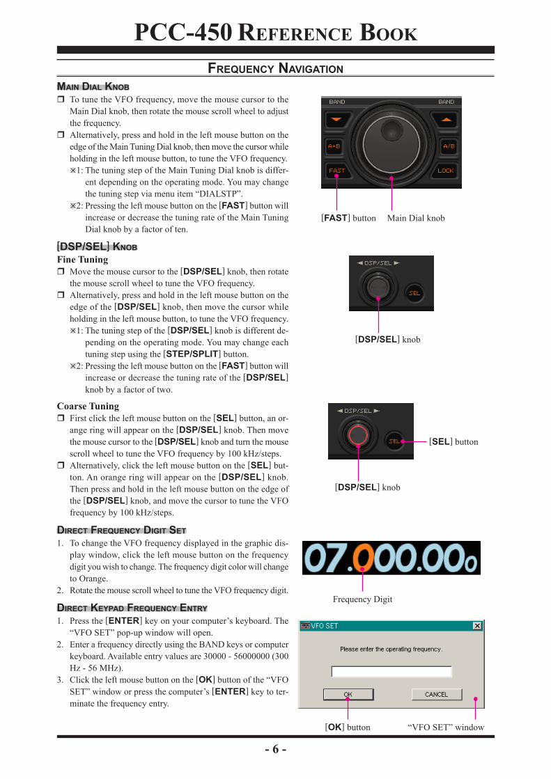
FREQUENCY NAVIGATIONMAIN DIAL KNOB
To tune the VFO frequency, move the mouse cursor to theMain Dial knob, then rotate the mouse scroll wheel to adjustthe frequency.Alternatively, press and hold in the left mouse button on theedge of the Main Tuning Dial knob, then move the cursor whileholding in the left mouse button, to tune the VFO frequency.
1: The tuning step of the Main Tuning Dial knob is differ-ent depending on the operating mode. You may changethe tuning step via menu item “DIALSTP”.
2: Pressing the left mouse button on the [FAST] button willincrease or decrease the tuning rate of the Main TuningDial knob by a factor of ten.
[DSP/SEL] KNOBFine Tuning
Move the mouse cursor to the [DSP/SEL] knob, then rotatethe mouse scroll wheel to tune the VFO frequency.Alternatively, press and hold in the left mouse button on theedge of the [DSP/SEL] knob, then move the cursor whileholding in the left mouse button, to tune the VFO frequency.
1: The tuning step of the [DSP/SEL] knob is different de-pending on the operating mode. You may change eachtuning step using the [STEP/SPLIT] button.
2: Pressing the left mouse button on the [FAST] button willincrease or decrease the tuning rate of the [DSP/SEL]knob by a factor of two.
Coarse TuningFirst click the left mouse button on the [SEL] button, an or-ange ring will appear on the [DSP/SEL] knob. Then movethe mouse cursor to the [DSP/SEL] knob and turn the mousescroll wheel to tune the VFO frequency by 100 kHz/steps.Alternatively, click the left mouse button on the [SEL] but-ton. An orange ring will appear on the [DSP/SEL] knob.Then press and hold in the left mouse button on the edge ofthe [DSP/SEL] knob, and move the cursor to tune the VFOfrequency by 100 kHz/steps.
DIRECT FREQUENCY DIGIT SET1. To change the VFO frequency displayed in the graphic dis-
play window, click the left mouse button on the frequencydigit you wish to change. The frequency digit color will changeto Orange.
2. Rotate the mouse scroll wheel to tune the VFO frequency digit.
DIRECT KEYPAD FREQUENCY ENTRY1. Press the [ENTER] key on your computer’s keyboard. The
“VFO SET” pop-up window will open.2. Enter a frequency directly using the BAND keys or computer
keyboard. Available entry values are 30000 - 56000000 (300Hz - 56 MHz).
3. Click the left mouse button on the [OK] button of the “VFOSET” window or press the computer’s [ENTER] key to ter-minate the frequency entry.
Frequency Digit
Main Dial knob[FAST] button
[DSP/SEL] knob
[DSP/SEL] knob
[SEL] button
“VFO SET” window[OK] button

PCC-450 REFERENCE BOOK
- 7 -
CLARIFIER OPERATION1. To turn the Clarifier on and off, click the left mouse button on
the [CLAR] button .2. Move the cursor to the Main Dial knob, then rotate the mouse
scroll wheel to tune the Clarifier offset frequency.Or, press and hold in the left mouse button on the edge of theMain Tuning Dial knob, then move the cursor while holdingin the left mouse button, to tune the Clarifier offset frequency.
3. Click the right mouse button on the [CLAR] button to clearthe Clarifier offset frequency (thereby setting the offset to“Zero”) when the Clarifier is activated.
You may also turn the Clarifier on and off by clicking the leftmouse button on the “CLAR” icon in the graphic displaywindow.
DIGITAL VOICE ANNOUNCEMENTTo announce the current operating frequency and operating modefrom the transceiver’s speaker, click the left mouse button on thetop half of the [VOICE/C.S] button.
AUDIO PLAYBACK FEATURERECORDING1. Click “Playback” in the “Option” menu on the menu bar, to
open the “Playback” pop-up window.2. Click the [REC] button in the “Playback” pop-up window to
initiate recording.3. Click the [STOP] button in the “Playback” pop-up window,
to stop recording.PLAYBACK1. Click “Playback” in the “Option” menu on the menu bar, to
open the “Playback” pop-up window.2. Click the left mouse button on the [PLAY] button in the “Play-
back” pop-up window, to begin playback of the recorded au-dio.
3. Click the left mouse button on the [STOP] button of the Au-dio Playback feature to stop the playback.
[CLAR] button
“CLAR” icon
[VOICE/C.S] button
“Playback” parameter
[STOP] button[PLAY] button
“Playback” window
[STOP] button[REC] button

PCC-450 REFERENCE BOOK
- 8 -
VOICE MEMORY FEATURERECORDING1. Click “Playback” in the “Option” menu on the menu bar, to
open the “Playback” pop-up window.2. Click the left mouse button on the desired Memory Channel
button (REC [Ch-1] or REC [Ch-2]) for the Voice Memoryfeature to initiate recording.
3. Click the left mouse button on the [STOP] button for theVoice Memory feature to stop recording.
PLAYBACK1. Click “Playback” in the “Option” menu on the menu bar, to
open the “Playback” pop-up window.2. Click the left mouse button on the desired Memory Channel
button (PLAY [Ch-1] or PLAY [Ch-2]) of the Voice Memoryfeature to begin playback of the recorded audio.
3. Click the left mouse button on the [STOP] button of the VoiceMemory feature to stop the playback.
TRANSMIT1. Click “Playback” in the “Option” menu on the menu bar, to
open the “Playback” pop-up window.2. Click the left mouse button on the desired Memory Channel
button (TX [Ch-1] or TX [Ch-2]) of the Voice Memory fea-ture to begin transmission of the recorded audio.
3. Click the left mouse button on the [STOP] button of the VoiceMemory feature to stop the transmission.
ATT (ATTENUATOR) & IPO (INTERCEPT POINT OPTIMIZATION)Click the left mouse button on the [ATT/IPO] button to openthe “ATT/IPO” pop-up window, then select the front-end sys-tem you wish to use.ATT OFF IPO OFF: Attenuator is OFF, and the incoming
signal is amplified by the RF pream-plifier.
ATT ON IPO OFF: Attenuator is ON, (the incoming sig-nal is reduced by 20 dB) and the in-coming signal is amplified by the RFpreamplifier.
ATT OFF IPO ON: Attenuator is OFF, and the incomingsignal bypasses the RF preamplifier,yielding direct feed to the first mixer.
ATT ON IPO ON: Attenuator is ON, (the incoming sig-nal power is reduced by 20 dB) andthe incoming signal bypasses the RFpreamplifier, yielding direct feed to thefirst mixer.
You may also select the front-end system you wish to use byclicking the left mouse button on the desired icon in the BlockDiagram Display in the graphic display window.
“Playback” parameter
PLAY [Ch-x] button
“Playback” window[STOP] button
REC [Ch-x] button
TX [Ch-x] button
[ATT/IPO] button
“ATT/IPO” window
IPO icon
Block Diagram Display
ATT icon

PCC-450 REFERENCE BOOK
- 9 -
RF GAIN CONTROLClick the left mouse button on the main [SQL/RF GAIN] knob(the indication color of “SQL/RF GAIN” will turn yellow), thenrotate the mouse scroll wheel or press the left/right buttons toadjust the RF gain.
NOISE BLANKER OPERATIONClick the left mouse button on the [NB] button to turn the NoiseBlanker “On” and “Off”.
You may also turn the Noise Blanker “On” or “Off” by click-ing the left mouse button on the “NB” icon of the Block Dia-gram Display of the display in the graphic display window.
AGCClick the left mouse button on the [AGC] button to open the“AGC” pop-up window, then select the receiver-recovery timeyou wish to use.AGC OFF: Disable the receiver AGC.AGC AUTO: Sets the receiver-recovery time auto-
matically depending on the operatingmode.
AGC FAST: Sets the receiver-recovery time to fast.This mode is suitable for CW/DATAreception.
AGC SLOW: Sets the receiver-recovery time to slow.This mode is suitable for SSB/AM re-ception.
You may also select the receiver-recovery time you wish touse by clicking the left mouse button on the “AGC” icon inthe Block Diagram Display in the graphic display window.
[NB] button
NB icon
Block Diagram Display
[AGC] button
AGC icon
Block Diagram Display
[SQL/RF GAIN] knob
“AGC” window
PCC-450 REFERENCE BOOK
- 10 -
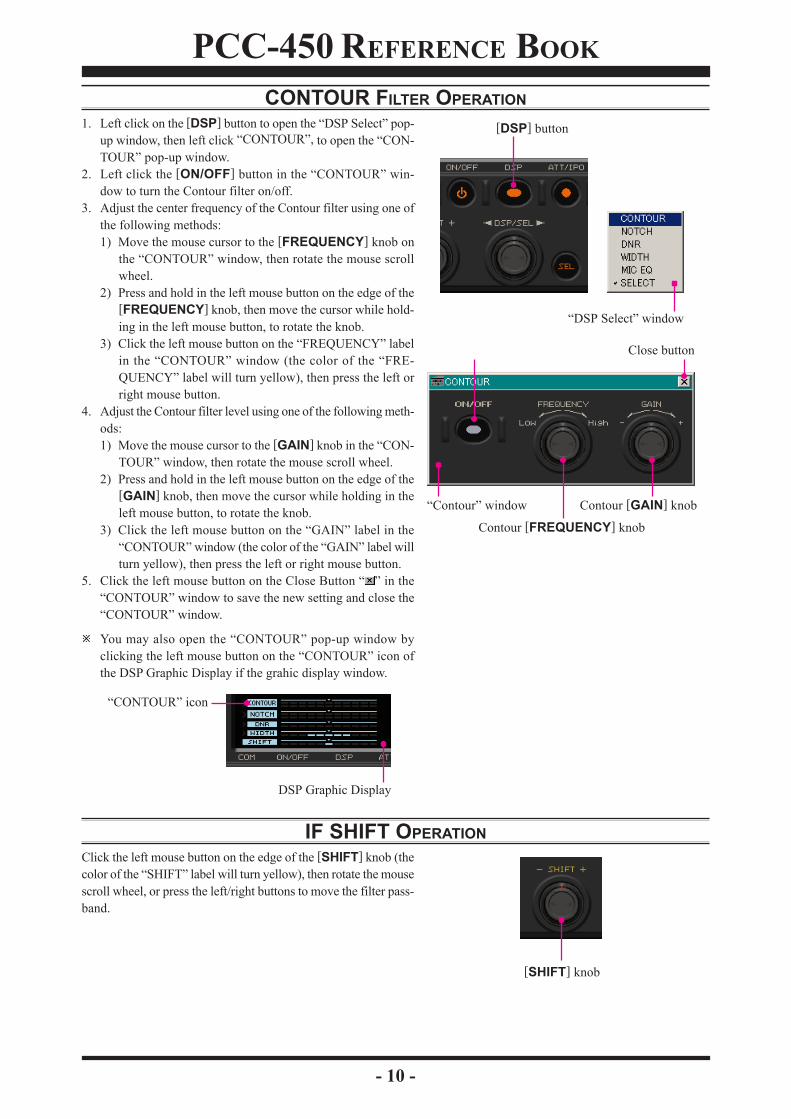
CONTOUR FILTER OPERATION1. Left click on the [DSP] button to open the “DSP Select” pop-
up window, then left click “CONTOUR”, to open the “CON-TOUR” pop-up window.
2. Left click the [ON/OFF] button in the “CONTOUR” win-dow to turn the Contour filter on/off.
3. Adjust the center frequency of the Contour filter using one ofthe following methods:1) Move the mouse cursor to the [FREQUENCY] knob on
the “CONTOUR” window, then rotate the mouse scrollwheel.
2) Press and hold in the left mouse button on the edge of the[FREQUENCY] knob, then move the cursor while hold-ing in the left mouse button, to rotate the knob.
3) Click the left mouse button on the “FREQUENCY” labelin the “CONTOUR” window (the color of the “FRE-QUENCY” label will turn yellow), then press the left orright mouse button.
4. Adjust the Contour filter level using one of the following meth-ods:1) Move the mouse cursor to the [GAIN] knob in the “CON-
TOUR” window, then rotate the mouse scroll wheel.2) Press and hold in the left mouse button on the edge of the
[GAIN] knob, then move the cursor while holding in theleft mouse button, to rotate the knob.
3) Click the left mouse button on the “GAIN” label in the“CONTOUR” window (the color of the “GAIN” label willturn yellow), then press the left or right mouse button.
5. Click the left mouse button on the Close Button “ ” in the“CONTOUR” window to save the new setting and close the“CONTOUR” window.
You may also open the “CONTOUR” pop-up window byclicking the left mouse button on the “CONTOUR” icon ofthe DSP Graphic Display if the grahic display window.
IF SHIFT OPERATIONClick the left mouse button on the edge of the [SHIFT] knob (thecolor of the “SHIFT” label will turn yellow), then rotate the mousescroll wheel, or press the left/right buttons to move the filter pass-band.
[DSP] button
“DSP Select” window
“CONTOUR” icon
DSP Graphic Display
Contour [FREQUENCY] knob
Contour [GAIN] knob“Contour” window
Close button
[SHIFT] knob
PCC-450 REFERENCE BOOK
- 11 -
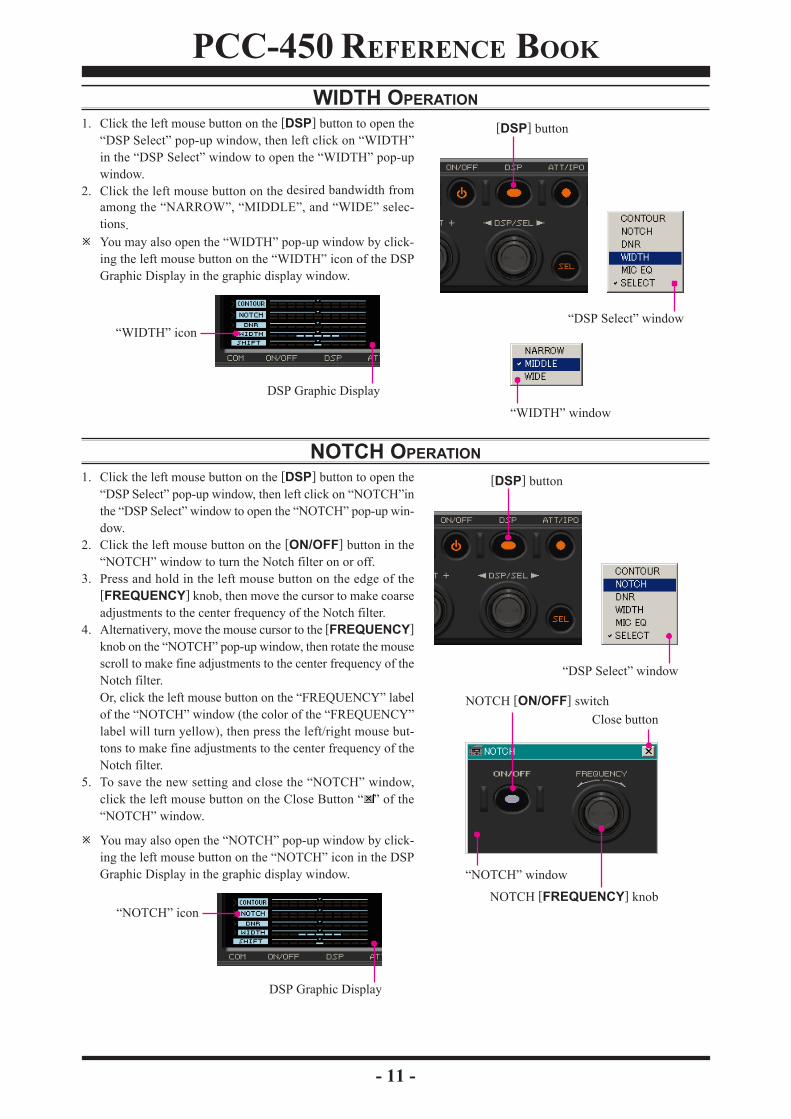
WIDTH OPERATION1. Click the left mouse button on the [DSP] button to open the
“DSP Select” pop-up window, then left click on “WIDTH”in the “DSP Select” window to open the “WIDTH” pop-upwindow.
2. Click the left mouse button on the desired bandwidth fromamong the “NARROW”, “MIDDLE”, and “WIDE” selec-tions.You may also open the “WIDTH” pop-up window by click-ing the left mouse button on the “WIDTH” icon of the DSPGraphic Display in the graphic display window.
NOTCH OPERATION1. Click the left mouse button on the [DSP] button to open the
“DSP Select” pop-up window, then left click on “NOTCH”inthe “DSP Select” window to open the “NOTCH” pop-up win-dow.
2. Click the left mouse button on the [ON/OFF] button in the“NOTCH” window to turn the Notch filter on or off.
3. Press and hold in the left mouse button on the edge of the[FREQUENCY] knob, then move the cursor to make coarseadjustments to the center frequency of the Notch filter.
4. Alternativery, move the mouse cursor to the [FREQUENCY]knob on the “NOTCH” pop-up window, then rotate the mousescroll to make fine adjustments to the center frequency of theNotch filter.Or, click the left mouse button on the “FREQUENCY” labelof the “NOTCH” window (the color of the “FREQUENCY”label will turn yellow), then press the left/right mouse but-tons to make fine adjustments to the center frequency of theNotch filter.
5. To save the new setting and close the “NOTCH” window,click the left mouse button on the Close Button “ ” of the“NOTCH” window.
You may also open the “NOTCH” pop-up window by click-ing the left mouse button on the “NOTCH” icon in the DSPGraphic Display in the graphic display window.
[DSP] button
“DSP Select” window“WIDTH” icon
DSP Graphic Display
“WIDTH” window
[DSP] button
“DSP Select” window
“NOTCH” icon
DSP Graphic Display
NOTCH [ON/OFF] switch
NOTCH [FREQUENCY] knob
“NOTCH” window
Close button

PCC-450 REFERENCE BOOK
- 12 -
DNR (DIGITAL NOISE REDUCTION) OPERATION1. Click the left mouse button on the [DSP] button to open the
“DSP Select” pop-up window, then click on “DNR”, to openthe “DNR” pop-up window.
2. Click the left mouse button on the [ON/OFF] button in the“DNR” window to turn the Digital Noise Reduction Systemon or off.
3. Select the setting that most effectively reduces the noise levelusing any of the following methods:1) Bring the mouse cursor to the [DNR] knob on the “DNR”
window, then rotate the mouse scroll wheel.2) Press and hold in the left mouse button on the edge of the
[DNR] knob, then move the cursor while holding in theleft mouse button.
3) Click the left mouse button on the “DNR” label in the“DNR” window (the indication color of the “DNR” labelwill turn yellow), then press the left or right mouse but-ton.
4. To save the new setting and close the “DNR” window, clickthe left mouse button on the Close Button “ ” on the “DNR”window.
You may also open the “DNR” pop-up window by clickingthe left mouse button on the “DNR” icon of the DSP GraphicDisplay in the graphic display window.
DSP MICROPHONE EQUALIZER1. To open the “MIC EQ” pop-up window, click the left mouse
button on the [DSP] button to open the “DSP Select” pop-upwindow, then click the left mouse button on the “MIC EQ”item.
2. Click on the button next to the desired equalizer pattern.Note: You can not move the individual slide bar symbols.
3. To save the new setting and close the “MIC EQ” window,click the left mouse button on the Close Button “ ” on the“MIC EQ” window.
[DSP] button
“DSP Select” window
“DNR” icon
DSP Graphic Display
[DSP] button
“DSP Select” window
DNR [ON/OFF] switch
[DNR] knob“DNR” window
Close button
“MIC EQ” window
Close button

PCC-450 REFERENCE BOOK
- 13 -
LOCK FEATURETo turn the Main Tuning Dial knob Lock “on”or “off”, left clickon the [LOCK] button .
You may also turn the Main Tuning Dial knob Lock “on” or“off” by clicking the left mouse button on the “LOCK” iconin the graphic display window.
REPEATER OPERATION1. To open the “Repeater” pop-up window, click “Option” in
the menu bar and then click “Repeater” in the drop-down list.2. In the “Repeater” pop-up window, click on [ENC], [SQL],
or [OFF], to select the desired CTCSS mode.3. Click on the “Freq” button to open the “CTCSS Tone Fre-
quency” pop-up window, and then select, and click on thedesired tone frequency.
4. Click the [OK] button to close the “CTCSS Tone Frequency”pop-up window.
5. Click the left mouse button on the [S], [–], or [+] button toselect the desired Repeater Shift Direction.
6. To save the new setting and close the “Repeater” pop-up win-dow, click the left mouse button on the Close Button “ ” inthe “Repeater” pop-up window .
You may also select the desired CTCSS mode by clicking theleft mouse button on the “ENC” / “DEC” icon in the graphicsdisplay window, and then select the desired Repeater ShiftDirection by clicking on the “–” / “+” icon in the graphicsdisplay window.
Note: You may select the CTCSS mode and Repeater Shift Di-rection only in FM mode.
[LOCK] button
“LOCK” icon
[OK] button
“CTCSS Tone Frequency” window
“Repeater” parameter
Close button
[+] button[Freq] button
[SQL] button[ENC] button
[OFF] button[–] button
[S] button
“Repeater” window
“ENC” “DEC” icon
“–” / “+” icon
PCC-450 REFERENCE BOOK
- 14 -
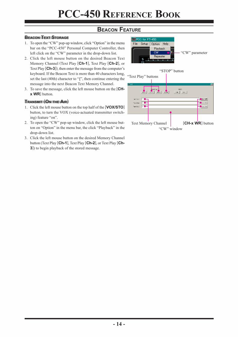
BEACON FEATUREBEACON TEXT STORAGE1. To open the “CW” pop-up window, click “Option” in the menu
bar on the “PCC-450” Personal Computer Controller, thenleft click on the “CW” parameter in the drop-down list.
2. Click the left mouse button on the desired Beacon TextMemory Channel (Text Play [Ch-1], Text Play [Ch-2], orText Play [Ch-3]), then enter the message from the computer’skeyboard. If the Beacon Text is more than 40 characters long,set the last (40th) character to “{”, then continue entering themessage into the next Beacon Text Memory Channel.
3. To save the message, click the left mouse button on the [CH-x WR] button.
TRANSMIT (ON THE AIR)1. Click the left mouse button on the top half of the [VOX/STO]
button, to turn the VOX (voice-actuated transmitter switch-ing) feature “on”.
2. To open the “CW” pop-up window, click the left mouse but-ton on “Option” in the menu bar, the click “Playback” in thedrop-down list.
3. Click the left mouse button on the desired Memory Channelbutton (Text Play [Ch-1], Text Play [Ch-2], or Text Play [Ch-3]) to begin playback of the stored message.
“CW” parameter
“STOP” button“Text Play” buttons
[CH-x WR] buttonText Memory Channel“CW” window

PCC-450 REFERENCE BOOK
- 15 -
CW SPOTTING1. To open the “CW” pop-up window, click on “Option” in the
menu bar on the “PCC-450” Personal Computer Controller,then click “CW” in the drop-down list.
2. Click SPOT [ON] button in the “CW” pop-up window, togenerate the CW Spot Tone.
3. Click the SPOT [OFF] button in the “CW” pop-up window,to stop the CW Spot Tone.
Note: You may activate the CW Spot Tone only in CW mode
TX/RXClick the left mouse button on the “TX” icon in the graphicdisplay window to activate the transmitter.Click the left mouse button on the “TX” icon again to returnto the receive mode.
“TX” icon
“CW” parameter
“SPOT” buttons
“CW” window

PCC-450 REFERENCE BOOK
- 16 -
OPERATION OF MISCELLANEOUS KNOBS AND BUTTONS[KEYER] BUTTONTo turn the Built-in Electronic Keyer “on” or “off”, left click onthe [KEYER] button .
You may also turn the Built-in Electronic Keyer “on” and“off” by left clicking on the “KEYER” icon in the graphicsdisplay window.
[A=B] BUTTONLeft click on the [A=B] button to copy the currently displayedVFO frequency (or a recalled memory channel) to the hiddenVFO; thus setting both VFO-A and VFO-B to the same frequencyand mode.
[A/B] BUTTONLeft click on the [A/B] button to toggle the frequency controlbetween VFO-A and VFO-B.
[TUNE] BUTTONLeft click on the [TUNE] button to open the “TUNER” pop-upwindow, then select the configuration you wish to use.
TUNER OFF: Disables the Automatic Antenna Tuner.TUNER ON: Activates the Automatic Antenna Tuner.TUNING: Begin automatic tuning.
You may also open the “TUNER” pop-up window by click-ing the left mouse button on the “TUNER” icon of the DSPGraphic Display in the graphics display window.
[F] BUTTONClick the left mouse button on the [F] button to engage the “Menu”mode.See page 20 for details.
[KEYER] button
“KEYER” icon
[A/B] button[A=B] button
“TUNER” window
[TUNE] button[F] button
“TUNER” icon

PCC-450 REFERENCE BOOK
- 17 -
[METER] BUTTONLeft click on the [METER] button, to open the “METER” pop-up window, and then select the meter function desired duringtransmit.
POWER: Indicates the average power output level.ALC: Indicates the relative ALC voltage.SWR: Indicates the Standing Wave Ratio (Forward/Re-
flected).
You may also select the function of the meter by clicking theleft mouse button on the “METER” icon in the graphic dis-play window.
[VOICE/C.S] BUTTONTo announce the current mode and operating frequency (withresolution to the displayed 100 Hz digit) from the transceiver’sspeaker, click the left mouse button on the top half of the[VOICE/C.S] button .Click the left mouse button on the bottom half of the [VOICE/C.S] button to open the “CUSTOM FUNCTION” pop-upwindow, then select the function you wish to use.MONITOR ON: Activates the Monitor feature to listen to
your transmitted voice signal.MONITOR OFF: Disables the Monitor feature.SPOT ON: Generates the CW Spot Tone when using
CW mode.SPOT OFF: Disables the CW Spot Tone.TXW ON: Activates the TXW feature which permits
monitoring the transmit frequency whenSplit Frequency operation is engaged.
TXW OFF: Disables the TXW feature.VCC: Opens the “VCC” pop-up window to dis-
play the DC supply voltage.AUX H: This function is for future expansion of
the transceiver’s capabilities.AUX L: This function is for future expansion of
the transceiver’s capabilities.Note: The functions of the “CUSTOM FUNCTION” win-dow are fixed. You can not arrange the window.
OPERATION OF MISCELLANEOUS KNOBS AND BUTTONS
[METER] button
“METER” window
“METER” icon
[MW/V/M] button[VOICE/C.S] button
“CUSTOM FUNCTION” window

PCC-450 REFERENCE BOOK
- 18 -
[MW/V/M] BUTTONTo store the current frequency into a memory channel, clickthe left mouse button on the top half of the [MW/V/M] buttonto open the “MEMORY WRITE” pop-up window. Type thedesired memory channel number into the “MEMORYWRITE” pop-up window text box.Click the left mouse button on the bottom half of the [MW/V/M] button to toggle the frequency control between the VFOand the Memory System.
Memory channels “P1L”, “P1U”, “P2L”, and “P2U” repre-sent “501”, “502”, “503”, and “504” respectively.
[HOME/RCL] BUTTONClick the left mouse button on the top half of the [HOME/RCL] button to recall the Home Channel on the band groupwhere you are currently operating (HF or 50 MHz).Click the top of the [HOME/RCL] button again to return tothe previously-used frequency (either a VFO or a memorychannel).Click the left mouse button on the bottom half of the [HOME/RCL] button to recall the QMB memory channel.Click the left mouse button again to return to the previously-used frequency (either a VFO or a memory channel).
[VOX/STO] BUTTONIn the SSB, AM, and FM modes, click the left mouse buttonon the top half of the [VOX/STO] button to turn the VOX(voice-actuated transmitter switching) feature “on” or “off”.In the CW mode, click the left mouse button on the top halfof the [VOX/STO] button to turn the CW Break-in (auto-matic activation of the transmitter when you close the CWkey) feature “on” or “off”.
You may also turn the VOX (voice-actuated transmitterswitching) feature “on” and “off” by clicking the leftmouse button on the “VOX” icon in the graphic displaywindow (in the SSB, AM, and FM modes). Turn the CWBreak-in (automatic activation of the transmitter when youclose the CW key) feature “on” or “off” by clicking theleft mouse button on the “BK-IN” icon in the graphic dis-play window (in the CW mode).
Click the left mouse button on the bottom half of the [VOX/STO] button to copy the operating information (frequency,mode, bandwidth, and also repeater direction/shift frequencyand CTCSS functions in FM mode) into the Quick MemoryBank.
OPERATION OF MISCELLANEOUS KNOBS AND BUTTONS
[VOX/STO] button[HOME/RCL] button
“BK-IN” icon
“VOX” icon
“MEMORY WRITE” window
PCC-450 REFERENCE BOOK
- 19 -
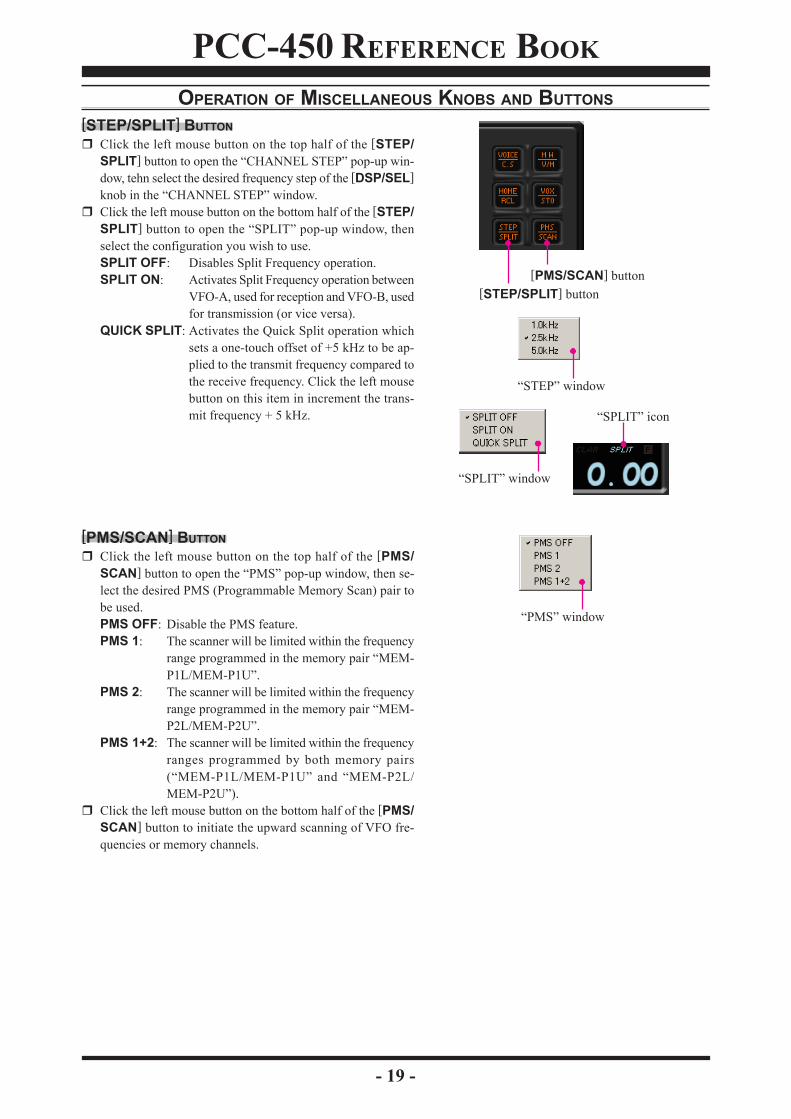
[STEP/SPLIT] BUTTONClick the left mouse button on the top half of the [STEP/SPLIT] button to open the “CHANNEL STEP” pop-up win-dow, tehn select the desired frequency step of the [DSP/SEL]knob in the “CHANNEL STEP” window.Click the left mouse button on the bottom half of the [STEP/SPLIT] button to open the “SPLIT” pop-up window, thenselect the configuration you wish to use.SPLIT OFF: Disables Split Frequency operation.SPLIT ON: Activates Split Frequency operation between
VFO-A, used for reception and VFO-B, usedfor transmission (or vice versa).
QUICK SPLIT: Activates the Quick Split operation whichsets a one-touch offset of +5 kHz to be ap-plied to the transmit frequency compared tothe receive frequency. Click the left mousebutton on this item in increment the trans-mit frequency + 5 kHz.
[PMS/SCAN] BUTTONClick the left mouse button on the top half of the [PMS/SCAN] button to open the “PMS” pop-up window, then se-lect the desired PMS (Programmable Memory Scan) pair tobe used.PMS OFF: Disable the PMS feature.PMS 1: The scanner will be limited within the frequency
range programmed in the memory pair “MEM-P1L/MEM-P1U”.
PMS 2: The scanner will be limited within the frequencyrange programmed in the memory pair “MEM-P2L/MEM-P2U”.
PMS 1+2: The scanner will be limited within the frequencyranges programmed by both memory pairs(“MEM-P1L/MEM-P1U” and “MEM-P2L/MEM-P2U”).
Click the left mouse button on the bottom half of the [PMS/SCAN] button to initiate the upward scanning of VFO fre-quencies or memory channels.
OPERATION OF MISCELLANEOUS KNOBS AND BUTTONS
[PMS/SCAN] button[STEP/SPLIT] button
“STEP” window
“SPLIT” window
“SPLIT” icon
“PMS” window

PCC-450 REFERENCE BOOK
- 20 -
MENU OPERATION1. Click the left mouse button on the [F] button to open the
“MENU” window.2. Rotate the mouse scroll wheel to select the Menu item you
wish to work on, then double click the left mouse button onthe Menu item to open the pop-up window.
3. Change the current setting of the selected Menu item, thenclick the [OK] button to close the pop-up window.
4. Click the [OK] button to save the new setting and close the“MENU” window.
[F] button
“MENU LIST” window
“MENU LIST SETTING” window
[OK] button

PCC-450 REFERENCE BOOK
- 21 -
COMMAND SEND1. Click the left mouse button on the “Command Send” param-
eter in the “File” menu on the “PCC-450” Personal Com-puter Controller to open the “Command Send” pop-up win-dow.
2. Enter the CAT command you wish send to the FT-450 withthe PC keyboard.For example: Set the VFO-A frequency to 14.250000 MHz.FA14250000;Refer to a “FT-450 CAT Operation Reference Book” for theCAT command.
3. Click the [OK] button to send the CAT command to the trans-ceiver and close the pop-up window.
“Command Send” parameter
[OK] button
“Command Send” window

PCC-450 REFERENCE BOOK
- 22 -
FUNCTION KEY OPERATIONYou can program and assign the CAT commands into your computer’s Function keys using the Vertex Standard KSE4PCCKeyboard Shortcut Editor, then you may control the transceiver by pressing your computer’s Function keys while activat-ing the “PCC450” Personal Computer Controller.
Each of the following 46 Function keys may be programmed with a CAT command sequence. There are a total of 52commands to chose from:
[F2] key ~ [F9] key, [F11] key, [F12] key,[Shift] + [F1] key ~ [Shift] + [F9] key, [Shift] + [F11] key, [Shift] + [F12] key,[Cntl] + [F1] key ~ [Cntl] + [F9] key, [Cntl] + [F11] key, [Cntl] + [F12] key,[Alt] + [F1] key ~ [Alt] + [F3] key, [Alt] + [F5] key, [Alt] + [F7] key ~ [Alt] + [F12] key,[Page Up] key, [Page Down] key, [Home] key, and [End] key
Following is an example of programming a CAT command shortcut into one of the Function keys:1. Copy the “KSE4PCC.exe” file into the folder where you in-
stalled the “PCC-450.exe” file.2. Double click the left mouse button on “KSE4PCC.exe” to
open the “Keyboard Shortcut Editor” pop-up window.3. Enter the CAT command you wish to assin to a specific Func-
tion key.Example 1: Set the VFO-A frequency to 14.250000 MHz.
FA14250000;Example 2: Set the Operating Mode to “USB”.
MD02;Example 3: Set the VFO-A frequecy to 14.250000 MHz,
USB mode.FA14250000; MD02;
(Notice in Example 3 that you may assign more than one CATcommand to a single function key. Simply add a semi-colonafter each command, and end the command line with a semi-colon).Refer to the “FT-450 CAT Operation Reference Book” forthe CAT command.Note: You can not enter CAT commands into the followingfunction keys.[F1] key, [F10] key, [Shift] + [F10] key,
[Cntl] + [F10] key, [Alt] + [F4] key, and [Alt] + [F6] key4. You may append an Alpha-numeric “Tag” to a CAT Com-
mand for your reference (This is for reference only. The Al-pha-numeric “Tag” is not displayed on the “PCC-450” Per-sonal Computer Controller).To append a “Tag” to your CAT shortcut key, click the leftmouse button on the “Tag” or the “Both” parameter in the“View” menu on the “Keyboard Shortcut Editor”. Your newreference “Tag” appears in the “Tag” column on the “Key-board Short-cut Editor”.
5. To close the “Keyboard Shortcut Editor” and save the CATcommands, click “File” in the menu bar, and then click “Save”in the drop-down list. In the Confirmation pop-up window,click the [Yes] button to save the new setting.
“View” menu
“Tag” column “Tag” column

PCC-450 REFERENCE BOOK
- 23 -
NOTE

PCC-450 REFERENCE BOOK
- 24 -
Copyright 2008VERTEX STANDARD CO., LTD.
All rights reserved
No portion of this manualmay be reproduced without
the permission ofVERTEX STANDARD CO., LTD.


![[XLS] · Web view450. 90. 450. 900. 900. 225. 450. 450. 900. 450. 225. 270. 4.5. 450. 450. 450. 450. 450. 450. 450. 450. 450. 900. 450. 450. 450. 112.5. 900. 900. 450. 112.5. 450](https://img.pdfslide.net/doc/110x75/5b3c17127f8b9a213f8d0b42/xls-web-view450-90-450-900-900-225-450-450-900-450-225-270-45.jpg)