Embed Size (px)
Citation preview

UNCLASSIFIED
Defense Technical Information CenterCompilation Part Notice
ADP014081TITLE: Programme for Life Extension and Widespread Fatigue DamageEvaluation to Ensure Continued Structural Integrity of Airbus LargeTransport Category Airplanes
DISTRIBUTION: Approved for public release, distribution unlimitedAvailability: Hard copy only.
This paper is part of the following report:
TITLE: Ageing Mechanisms and Control. Specialists' Meeting on LifeManagement Techniques for Ageing Air Vehicles [Les mecanismesvieillissants et le controle] [Reunions des specialistes des techniques degestion du cycle de vie pour vehicules aeriens vieillissants]
To order the complete compilation report, use: ADA415672
The component part is provided here to allow users access to individually authored sectionsof proceedings, annals, symposia, etc. However, the component should be considered within-he context of the overall compilation report and not as a stand-alone technical report.
The following component part numbers comprise the compilation report:ADP014058 thru ADP014091
UNCLASSIFIED

(SM) 29-1
Programme for Life Extension and Widespread FatigueDamage Evaluation to Ensure Continued Structural Integrity
of Airbus Large Transport Category Airplanes
Hans TreyStructure Analysis, Damage Tolerance Department (ESADG)
and Hans-Juergen SchmidtMetal Design Principles (ESO) and Fatigue and
Damage Tolerance Department (ESG-O)EADS Airbus GmbH
Fatigue and Fracture Mechanics Dept (EMF)Kreestslag 10
D-21129 HamburgGermany
Keywords ageing aircraft, life extension, widespread fatigue damage, Monte Carlo Simulation
Abstract
The Airworthiness Assurance Working Group (AAWG) has been charted by FAA to enhance anddevelop rules for continued structural integrity of large transport category airplanes. The subgroupAAWG - RWG (Rule Writing Group) has completed a draft proposal for enhancement of AC91-56and the introduction of operational rules of aircraft operated under 14 CFR Parts 91, 121, 125, 129 and135.The Airbus activities to meet the new regulations are in progress for the Airbus types A300B2,A300B4-100, A300B4-200 and A300B4-600. This paper describes details of tests, analysis andprocedures to meet the new requirements and recommendations. The presentation discusses especiallythe activities for the pressurized fuselage, which is mainly under the responsibility of AirbusDeutschland GmbH.The Airbus Life Extension activities include a general review of the fatigue and damage toleranceanalysis prepared for type certification, interpretation of full scale fatigue test findings, tear downresults and SB review with respect to extended service goals.Special emphasis will be given to the investigation and analysis of Widespread Fatigue Damage(WFD). Compliance must be ensured with the new requirements, which concern the need to limit thevalidity of the current structural maintenance programme and the need to impose operationalrequirements that mandate a structural maintenance programme to prevent WFD in the fleet. TheWFD evaluation of the fuselage will be performed using a new analysis tool developed in a Europeanresearch programme and extended and validated by Airbus Deutschland GmbH within the last years.The new analysis tool is verified by extensive coupon and panel testing comprising fatigue, crackgrowth and residual strength'ests for the major areas potentially susceptible to WFD.Another important topic of the life extension activities is the prevention of corrosion in the ageingfleet. Therefore a Corrosion Prevention and Control Programme (CPCP) was established which isreviewed periodically.In addition the structure of a retired high-time A300 is investigated in detail to support the lifeextension activities. Tear down investigation of critical areas and areas potentially susceptible to WFDare performed. Several structural parts, e.g. large panels are cut out of the airframe and tested forfatigue, crack growth and residual strength capabilities. In addition material properties, i.e. crackgrowth data and fracture toughness data will be determined for the aged structure and compared tomore recent values.
Paper presented at the RTO A VT Specialists'Meeting on "Life Management Techniques for Ageing Air Vehiclesheld in Manchester, United Kingdom, 8-11 October 2001, and published in RTO-MP-079(1 ).

(SM) 29-2
Status of Airbus Fleet
The A300 aircraft was the first of the Airbus types and approximately 500 aircraft are currently inservice. This number includes an increasing number of older aircraft converted from passenger tofreighter configuration. The A300 entered airline operation in May 1974 and production of theA300B4-600 variant continues today, however, some early models of the A300 are now approachingtheir Design Service Goal (DSG), i.e. the number of flight cycles or flight hours during which theprincipal structure is expected to be reasonably free from significant cracking.As can be seen from Figure 1 the Airbus fleets are still relatively young with the majority of theairplanes below 50 percent of their DSG [1]. No Airbus aircraft has reached its DSG up to now.However, in May 1999 26 A300 as well as 15 A300-600 aircraft had exceeded 75 percent of theirDSG. The high-time A300 B2/B4 and A300-600 aircraft will reach their DSGs within the next fewyears. In 1997 a forecast of the fleet status was made for planning of the Airbus life extensionactivities. Figure 2 shows the development of the A300 variants for the years 2001 to 2005. Especiallya considerable number of A300B4-600 aircraft will reach the DSG very soon. Consequently, lifeextension activities including widespread fatigue damage evaluation are needed.
800 - - - --- - -------
700-Fn5;G
500 <
r> 300 D
200
0-A300 A300 A310 A319 A320 A321 A330 A340
-600
Figure 1: Age of Airbus A300 Fleet
SO~~ A300B4- 100.- -
S14 - A300B4-200-• • A300B4-600
12 i
'- 108
S64 -
z
2•0 -
2001 2002 2003 2004 2005
Figure 2 :Predicted Development of Airbus A300 Fleet

(SM) 29-3
New Design Service Goals
The original DSG is generally established at the time of type certification and is not intended to limitthe life of the structure, or to define the point at which the aircraft can not continue its operation. In thecase of the A300 aircraft, operators have requested continued operation beyond the DSG, and the issueof an extension of the service life is now being addressed. In close cooperation with the operatorsAirbus has defined new, extended service goals (ESG) for the various A300 models. The table belowsummarizes the new ESGs:
A/C Type Design Service Goal [Fe] Extended Servi6e0Goal 0 FC Increase 2%5A300 B2 48e000 60 000 25
A300 B4-100 40000 57000 42.5A300 B4-200 34 000 42 500/57 000 25/67.6A300 B4-600 30 000 42 500 42
General Approach
To reach the above new ESGs Airbus Industry has launched a Full Life Extension Programme for theA300 aircraft. In order to justify a further period of operation up to the new ESG, it is necessary toreview service experience and re-assess the existing inspection programmes. This may lead to amodification of the maintenance strategy, including the inspection of additional items or an increasedlevel of surveillance in some areas.The following activities are performed under the A300 Full Life Extension.
Fatigue and damage tolerance analysis of the original structure and modifications including:o Detailed identification of the concerned areao Review of Full Scale Fatigue Test (A300, A3 10) and in-service experienceso Loads comparison for all variantso Review of former fatigue justificationso New calculationso Review of Service Bulletins and current inspection programme
* Widespread Fatigue Damage Analysis* Update of all inspection programmes incl. MRB, SSIP and the definition of new programmes* Definitions of modifications or replacement of structure including embodiment threshold
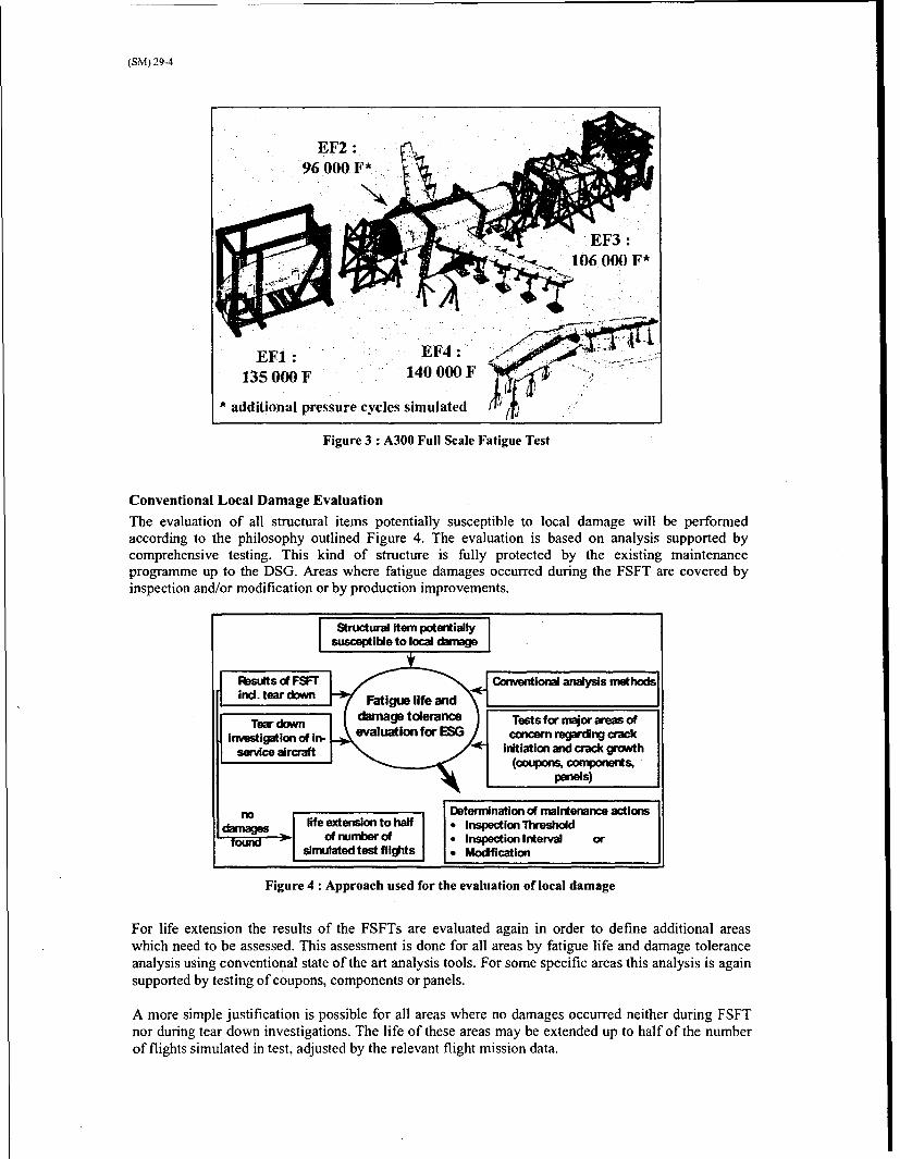
In addition to these activities all repairs and in-service problems that were monitored by the operatormust be considered in the ESG analysis. Therefore a complete review of all repairs, in-serviceproblems and of the Structural Repair Manual (SRM) is required.The activities are especially tuned to the pressurized fuselage, which is mainly under the responsibilityof Airbus Deutschland GmbH. Additionally some areas of the Vertical and Horizontal Tailplane areinvestigated.All activities are supported by comprehensive WFD and local damage testing and tear downinvestigation of a retired airframe.Furthermore, the life extension activities including WFD evaluation are significantly supported by theresults of the full scale fatigue tests. The A300 aircraft was tested in a multi-section test for at leasttwo lifetimes. Figure 3 shows the four A300 FSFT specimens together with the number of simulatedflights.For the assessment of areas susceptible to local damage only a conventional fatigue and damagetolerance analysis may be used. However, for the analysis of WFD susceptible areas a new approachwas developed.
(SM) 29-4
96 000 F* . .
.•: .106. 000 F*
EF1: EF4:1350900F 140 000 F
* additional pressure cycles simulated
Figure 3 : A300 Full Scale Fatigue Test
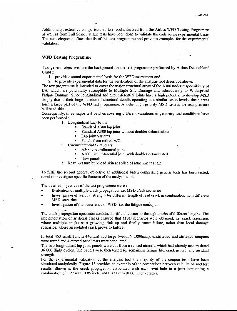
Conventional Local Damage Evaluation
The evaluation of all structural items potentially susceptible to local damage will be performedaccording to the philosophy outlined Figure 4. The evaluation is based on analysis supported bycomprehensive testing. This kind of structure is fully protected by the existing maintenanceprogramme up to the DSG. Areas where fatigue damages occurred during the FSFT are covered byinspection and/or modification or by production improvements.
1Structure! Item potentiallysusceptible to local damage
R ts of Fortir anlss ehd
Tow dow damage tolerance Tests for major areas of-evaluaton for ESG concern regarding crack
inv~etigatiof iInitiation and crack growth(coupons, componmts"
paels)
lo Deternination of maintenance actionsdmg life extension to half 9 Inspection Threshold
found 31 of number of * Inspection Interval orsimulated test flights * Modification
Figure 4 : Approach used for the evaluation of local damage
For life extension the results of the FSFTs are evaluated again in order to define additional areaswhich need to be assessed. This assessment is done for all areas by fatigue life and damage toleranceanalysis using conventional state of the art analysis tools. For some specific areas this analysis is againsupported by testing of coupons, components or panels.
A more simple justification is possible for all areas where no damages occurred neither during FSFTnor during tear down investigations. The life of these areas may be extended up to half of the numberof flights simulated in test, adjusted by the relevant flight mission data.

(SM) 29-5
Widespread Fatigue Damage Evaluation
Since fatigue crack initiation becomes more likely with extended service, the evaluation of structuralitems potentially susceptible to WFD requires a more complex analysis.With extended operation there is an increased probability of Multiple Site Damage (MSD), i.e. thesimultaneous presence of multiple fatigue cracks in the same structural element, or Multiple ElementDamage (MED), i.e. the simultaneous presence of multiple fatigue cracksý in similar adjacentstructural elements. MSD and MED can seriously degrade the damage tolerance capability, i.e. theresidual strength of the structure, and may develop into Widespread Fatigue Damage (WFD), which isdefined as the point where the structure is no longer able to meet the required level of residualstrength. Thus, the prevention of WFD is an important issue to the continued safe operation of ageingaircraft, and special WFD analysis methods have been developed.Following discussions between the manufacturers, aircraft operators and regulatory authoritiesundertaken by the Ageing Aircraft Working Group (AAWG), a draft proposal for enhancement ofAC91-56 and the introduction of operational rules for aircraft operated under 14 CFR Parts 91, 121,125, 129 and 135 was issued [2]. Compliance must be ensured with the new requirements, whichconcern the need to limit the validity of the current structural maintenance programme and the need toimpose operational requirements that mandate a structural maintenance programme to prevent WFD inthe fleet.The new rule requires the introduction of specific detailed inspections for MSD/MED, and thedeclaration of an 'Inspection Start Point (ISP)', where special WFD inspections must be started, andan operational limit, known as the 'Structural Modification Point (SMP)', beyond which a structuralitem may not be used without modification because of the increased risk of WFD. The SMP is derivedfrom the average expected behavior. Beyond this point the airplane may not be operated withoutfurther evaluation and modification. The SMP is established so, that operation up to the point providesequivalent protection to that of a two lifetime fatigue test.For structure where the MSD/MED situation is reliably detectable before it becomes critical a so-called monitoring period may be defined and applied before other means have to be taken. Themonitoring period is the period of time between ISP and SMP. Repeat inspection intervals areestablished based on the length of time from detectable fatigue cracks to the average WFD divided bya factor.Consequently, for each structural item potentially susceptible to WFD the analysis method mustprovide both the ISP and the SMP, as well as the interval of repeat inspections during the monitoringperiod. An example is shown in Figure 5, where MSD inspections start at 36000 FC with an repeatinspection interval of aprox. 7000 FC until the SMP is reached at 54000 FC. These values werederived according to the recommendations provided by the AAWG, which state that SMP and ISP aredetermined by applying a factor of 2 and 3 on the WED Average Behaviour, respectively.
Monitoring Period
6900 Rt 6900 Rt Rights
0 Inspection Structure WFD Averame,Startng Point, Modification 108,000 FlRs.
36,000 &ts. Point54,000 Rts.
Figure 5 : Example of Determination of Inspection Programme
The WFD phenomenon is commonly associated with longitudinal or circumferential fuselage lapjoints, such as in the Aloha Airlines Boeing 737 accident of April 1989, in which widespread fatigueand corrosion damage in a high-time aircraft led to an in-flight structural failure and explosivedecompression [3]. Although initially independent, the development of these cracks may eventuallylead to interaction and link-up of damage sites, and the possibility of structural failure.

(SM) 29-6
The structural items within the fuselage structure of a commercial large transport category aircraft thatare potentially susceptible to MSD/MED have been identified by the AAWG [2]. These locations aresummarized as follows:
"* Longitudinal Skin Joints, Frames and Tear Straps (MSD/MED)"* Circumferential Joints and Stringers (MSD/MED)"* Lap Joints with Milled, Chem-milled or Bonded Radius (MSD)"* Fuselage Frames (MED)"* Stringer to Frame Attachments (MED)* Shear Clip End Fasteners on Shear Tied Fuselage Frames (MSD/MED)* Aft Pressure Dome Outer Ring and Dome Web Splices (MSD/MED)* Skin Splice at Aft Pressure Bulkhead (MSD)* Abrupt Changes in Web or Skin Thickness Pressurized or Unpressurized Structure (MSD/MED)* Window Surround Structure (MSD/MED)* Latches and Hinges of Non-plug Doors (MSD/MED)* Skin at Runout of Large Doubler (MSD) Fuselage, Wing or Empennage
In the case of the Airbus A300, a number of specific structural features may be identified thatcorrespond to the generic items in the above list. These locations must be considered during the WFDassessment required to justify extended service of the aircraft.
The general approach for the WFD assessment used by Airbus Deutschland GmbH is presented inFigure 6. As for the local damages the results of the FSFTs including tear down are taken into account,but furthermore specific analysis methods are necessary to determine the WFD parameters.Additionally, a large testing programme was launched to investigate the behaviour of structural itemsin the presence of MSD.Both the WFD analysis tool and the WFD Testing Programme are described in the following chapters.
Structural item potentially1susceptible to WFDJ lAnalysis method developed
Riesults of FSFT [ in frame of Brite-EuramInd. tear down SMAAC project
Tear down evaluation Gene,_ctests regardinginvestagation of .crack initiation, crackinvesigation • " growth and residual
insevie aircraf.t jstrength
Determination of WFD parameters: Tests for major areas of"* Threshold for Monitoring Period concern regarding crack" Inspection Interval Initiation, crack growth and" Structure Modification Point residual strength (coupons,
modification or replacement components, panels)
Figure 6: Approach used for WFD Evaluation
Widespread Fatigue Damage Analysis
Effect of MSDThe cause of the Aloha Airlines accident was assigned to the presence of small cracks at adjacentfastener holes, MSD, in a skin lap splice leading to inflight structural failure of the upper part of theforward fuselage [3]. Therefore, the main issue of the aging aircraft fleet is the occurrence of multiple

(SM) 29-7
damages at adjacent locations (MSD, MED) which influence each other. This so-called 'interaction ofcracks' leads to higher stress intensity factors at the crack tips and consequently to higher crackpropagation rates.The effect of MSD is shown in Figure 7. In the presence of MSD adjacent to a lead crack the residualstrength is reduced drastically. The drop of the residual strength from the capability of the intactstructure to the capability required to withstand the design loads occurs in a much shorter timecompared to the case of a local damage. Furthermore the crack growth for a MSD scenario isincreased compared with the single crack. Together with the reduced critical crack length, this resultsin a significantly reduced crack growth period between the detectable and critical situation. Thediagram also acknowledges the fact that while the MSD crack growth and residual strengthdegradation occurs in a more rapid sense, it is also expected to occur later in the life of a structuraldetail. This very rapid decrease of the residual strength in MSD situations due to crack interaction andaccelerated crack growth must be taken into account during each analysis process.
./MSD/MED ResidualSStrength
Local Damage Residual Strength(may occur at any time)
---------------------------- ....--- .- - - --- ...... ----- -.............. ---- .. .. C.. . . ."noMSD ith MSD
St t t t t \ t t t t f a•
crack growth period crack cdtical damage sizel ocal damage -- "-"growth "• .....-... lclSperiod e i--------------
: i• •MSD •.. critical damage sizeS-- - (MSD)
- ------------------- -detectable damagesize
flightcycles
Figure 7: Effect of MSD
Analysis Method
The analysis method for WFD evaluation was mainly developed by of the European research project'Structural maintenance of Ageing Aircraft' (SMAAC) [4], partly founded by the EuropeanCommission. Significant additional effort was undertaken at Airbus to derive and validate anengineering tool for the Airbus structure to be evaluated. The development of this engineering toolwas supported by extensive testing, which is described in the next chapter.The main objective of the method is to estimate the development and evolution of MSD/MED in anaircraft structure. This information would permit the definition of an inspection programme forMSD/MED cracking. At a fundamental level, the methodology attempts to model both the initiation ofmultiple cracks at repetitive features within a structure susceptible to MSD/MED (e4g. a fastener holein a lap joint), and the subsequent growth of those cracks after initiation. In the approach used byAirbus this is done by means of a Monte-Carlo simulation, where multiple initial crack scenarios arerandomly generated and for each scenario subsequent crack propagation and failure is calculated(Figure 8). The method is summarized as follows [4]:"* The first step is the definition of the initial damage scenario. Each potential crack location (e.g.
two sides per fastener hole in a lap splice) is allocated a crack initiation time. The initiation timeis determined by randomly drawing a "life" from an overall log-normal distribution of fatiguelives for simple coupons.
"* The propagation of each initiated crack is calculated through the techniques of linear elasticfracture mechanics. The major parameter within each crack propagation calculation is the stressintensity factor at the crack tip. Due to the nature of the MSD problem, within this model anumber of solutions account for the interaction of cracks with other cracks. Plasticity effects areaccounted for by considering Irwin's plastic zone in front of each crack tip. There are differentways of calculating the stress intensity factor, for example FEM, BEM, complex stress functionsor compounding. Since a very important feature within a Monte-Carlo Simulation is the

(SM) 29-8
computer time consumption, this model uses the compounding method, because it combinesreasonable accuracy with very short calculation time compared to other methods."A damage accumulation procedure accounts for the effect of stress redistribution on theinitiation of additional cracks. This stress redistribution is a consequence of the occurrence andgrowth of cracks Three main effects are considered here: the increase of net stress, the stressincrease at the uncracked side of a cracked hole and the stress increase at an uncracked holeadjacent to a cracked hole. The increased accumulation of damage due to these effects leads toearlier crack initiation at the considered locations. This type of damage accumulation ensures arealistic simulation of the MSD behaviour in WFD susceptible components.
"* Damage accumulation and crack propagation stop at failure. Three different failure criteria maybe applied : reaching a critical stress intensity factor, net section yielding or exceeding a givenlead crack size. A reliable estimate of the residual strength of a component in the presence ofMSD is needed to complete the WFD analysis. Therefore, a R-curve analysis procedure hasbeen implemented, which accounts for crack interaction. In this procedure each crack tip of asimulated crack scenario is investigated for unstable crack extension
D efno .n
Iý I N'T71
_ _ .__ ___ _
::Statistical analysis <;i .• ••. ' .. ••:7...of the results : :••':'°:•;:•:•-• •
Figure 8: Flow Chart of WFD Analysis Method
These stages form a single Monte-Carlo iteration (Figure 9) and are repeated many times to form acomplete Monte-Carlo simulation of the structural item under investigation. The results of n iterationsare evaluated statistically to obtain probability distributions, mean values and standard deviation forthe Time to Initiation (left/blue curve in Figure 10), the Time to Detectable (mid/green curve in Figure10)and the WFD Average Behaviour / mean of Time to Failure/Endurance (right/red curve in Figure10).

(SM) 29-9
MSD Configuration 2 Std LL, no del, full doubler, TTS=1.27
ito
s-kdh'- rLA tKii44)4lUtt if L Li- Failure:
I I It it :: lllllj: 11 It 11 [1 1 1 11 110 175FIG- .. I II I It It I I
-L.mwi 7I I It 1 11"If it 11 1! 1 _ . i I it it II . tt _ I Il i t I I I
"- I I I II II II I ttj! I I II tI I tit II II II II II I, I t II 1 0 7 FIs I 1 11 [1 11 1 1 f t t-it if it 11 it it if • I II IJif
Po it "I I I- 2 ~~t 7 7Flitiation of first crack I
, I I ! i I It 1 i t l i I1 II It i it i II f t IIII t
I I 11 11 If I i It II 1i 1 tl I t II II I t II It
III It Ii It I t I
!i I I al IJ. i l i I II It II II liI I ! itI ! I I ! I
It I" I II It I t-- II i If II-/ 1 1 "- -1 1 1 1I- I I 1 1 It It I I i It FC it i t o I I t 11 It a 1 it I I I
- - t•¢ I I I It I t II It i II I1" II II f II iI il i I II I t' I I" li
I I i it I I If ii 1t It if II I1 t I f t i1 i 1 II It 1 1 1I. i I *I II II I I II II II I1 II t II II II II I I I!
II I ! I ! It It It I I II it Ii I t I t I tI t 1 It I It*~ il I I ft I II II It It It I t II ii II It I t It I t It I I
-I ; IgI2 It I t It II W3 II II I I . t1 I t II II II II
. 11, 33 55. 77 9 121 143 165. 187 259 231. 253. 275, 2q7, 319- 341. 363. 385. 407 429 454W,CacS LWVM4 IMM MDs0s44o4"
Figure 9 : Result of a single Monte Carlo Iteration : shown is the evolution of a scenario in a lap joint, i.e.the position of crack tips/holes against the number of cycles
Results of Simulation: Std LL, no del, full doublet, TTS= 1.27
MOM End : W 07737sOff Ent.53. E '.
-7 ln. i- -- '- -- N.0Mea k~jmattn M 214.Sftv ikisteaion 0WM
A 7oX eonSI ki MPO 8 .1.00
InputM• 5.190I lOut&SDv AG60O
II t
* S
- - - - - - - - -
0. fII= t'+/• ++Sl•a T8O CO Jl848J ,M48
I I -i' I: I : , **jI. I I 1 * * I , , *l'
1 2 3 4 5 6 7 8 9 10 '11 12 13 14
Number of Iterations: 5W0 No of Cycles x 10-4 MSiSWnim 04,M
Figure 10 : Results of a complete Monte Carlo Simulation comprising 500 iterations

(SM) 29-10
For relatively simple situations, such as constant amplitude cyclic loading, it is possible to evaluaterapidly many individual Monte Carlo scenarios with reasonable computational effort (of the order of100 scenarios per minute on a UNIX workstation). To obtain stable results the number of Monte Carloiterations performed should be in the order of 250 to 500 as illustrated in Figure 11. However, theincorporation of more complex features within the model, such as the calculation of crack growthunder spectrum loading or the use of sophisticated techniques such as finite element modeling wouldrequire significantly more computation time and would therefore limit the number of scenarios. Acareful balance between accuracy and speed needs to be achieved.
.U 7"°:':14 ,Conver, .ence of Model
6.5,104 -JU
6.0>.104
0 4
r 5.5;'104
5.0x 10⁴
0 4"5104
0 100 200 300 400 500Number of configurotions
Figure 11: Number of Monte Carlo iterations to obtain a stable mean value
The analysis tool (MSDSim) has been validated theoretically through comparison to existing fracturemechanics tools, such as NASGRO [5], FRAN2D [7][8][9], AFGROW [6], etc. An example is givenin Figure 12 : Special. emphasis has been given to the investigation of the crack interactionphenomenon. The stress intensity factors calculated for two approaching crack tips have beencompared to the FRANC2D calculation to ensure accurate performance of the code.
(nTipsm d8•F
kt'xmbivwmtvoa•a~t a ednn •frcnmdriarhdFranc2lD - model
a[rm4
l" toa 2 r• c hde- Mwado al~o rkt h:3 * Po•DS1 caR'Mk e2-~w1jga,5cgvhoad~ot hre3]
Figure 12 :Comparison of stress intensity factor calculation for two interacting cracks
(SM) 29-11
Additionally, extensive comparisons to test results derived from the Airbus WFD Testing Programmeas well as from Full Scale Fatigue tests have been done to validate the code on an experimental basis.The next chapter outlines details of this test programme and provides examples for the experimentalvalidation.
WFD Testing Programme
Two general objectives are the background for the test programme performed by Airbus DeutschlandGmbH:
1. provide a sound experimental basis for the WFD assessment and2. to provide experimental data for the verification of the analysis tool described above.
The test programme is intended to cover the major structural areas of the A300 under responsibility ofDA, which are potentially susceptible to Multiple Site Damage and subsequently to WidespreadFatigue Damage. Since longitudinal and circumferential joints have a high potential to develop MSDsimply due to their large number of structural details operating at a similar stress levels, these areasform a large part of the WFD test programme. Another high priority MSD item is the rear pressurebulkhead skin.Consequently, three major test batches covering different variations in geometry and conditions havebeen performed:
1. Longitudinal Lap Joints"* Standard A300 lap joint"* Standard A300 lap joint without doubler delamination"* Lap joint variants"u Panels from retired A/C
2. Circumferential Butt Joints"* A300 circumferential joint"* A300 Circumferential joint with doubler delaminated"* New panels
3. Rear pressure bulkhead skin at splice of attachment angle
To fulfil the second general objective an additional batch comprising generic tests has been tested,tuned to investigate specific features of the analysis tool.
The detailed objectives of the test programme were:* Evaluation of multiple crack propagation, i.e. MSD crack scenarios,* Investigation of residual strength for different length of lead crack in combination with different
MSD scenarios* Investigation of the occurrence of WFD, i.e. the fatigue concept.
The crack propagation specimen contained artificial comer or through cracks of different lengths. Theimplementation of artificial cracks ensured that MSD scenarios were obtained, i.e. crack scenarios,where multiple cracks start growing, link up and finally cause failure, rather than local damagescenarios, where an isolated crack grows to failure.
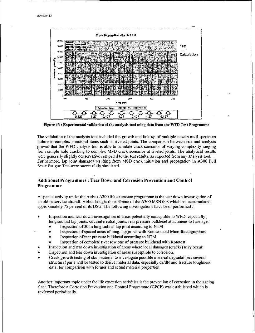
In total 463 small (width 440mm) and large (width > 1000mm), unstiffened and stiffened couponswere tested and 4 curved panel tests were conducted.The two longitudinal lap joint panels'were cut from a retired aircraft, which had already accumulated36 000 flight cycles. The panels were then tested for remaining fatigue life, crack growth and residualstrength.For the experimental validation of the analysis tool the majority of the coupon tests have beensimulated analytically. Figure 13 provides an example of the comparison between calculation and testresults. Shown is the crack propagation associated with each rivet hole in a joint containing acombination of 1.27 mm (0.05 inch) and 0.127 mm (0.005 inch) cracks.
(SM) 29-12
Cack Propagation- Batch 5.1.6
2000 Test
16000!
" 14000 Calculation
000
100 150 200 250 300 350
Xb (1mm)
O~~tn- Kaiw 8043-2264-15 EYA(3-2264-161
-0- -& <>o--- < -& -0- -&--0-0.127 1.27 0.127 1.27 0.127 1.27 0.127
Figure 13 : Experimental validation of the analysis tool using data from the WFD Test Programme
The validation of the analysis tool included the growth and link-up of multiple cracks until specimenfailure in complex structural items such as riveted joints. The comparison between test and analysisproved that the WFD analysis tool is able to simulate crack scenarios of varying complexity rangingfrom simple hole cracking to complex MSD crack scenarios at riveted joints. The analytical resultswere generally slightly conservative compared to the test results, as expected from any analysis tool.Furthermore, lap joint damages resulting from MSD crack initiation and propagation in A300 FullScale Fatigue Test were successfully simulated.
Additional Programmes : Tear Down and Corrosion Prevention and ControlProgramme
A special activity under the Airbus A300 life extension programme is the tear down investigation ofan old in-service aircraft. Airbus bought the airframe of the A300 MSN 008 which has accumulatedapproximately 75 percent of its DSG. The following investigations have been performed:
* Inspection and tear down investigation of areas potentially susceptible to WFD, especially_longitudinal lap joints, circumferential joints, rear pressure bulkhead attachment to fuselage.* Inspection of 50 m longitudinal lap joint according to NTM- Inspection of special areas of long. lap joints with Rototest and Microfractographics"* Inspection of rear pressure bulkhead according to NTM"* Inspection of complete rivet row one of pressure bulkhead with Rototest
* Inspection and tear down investigation of areas where local damages (cracks) may occur.."* Inspection and tear down investigation of areas susceptible to corrosion."• Crack growth testing of skin material to investigate possible material degradation : several
structural parts will be tested to derive material data, especially da/dN and fracture toughnessdata, for comparison with former and actual material properties
Another important topic under the life extension activities is the prevention of corrosion in the ageingfleet. Therefore a Corrosion Prevention and Control Programme (CPCP) was established which isreviewed periodically.

(SM) 29-13
Conclusion
Since an increasing number of Airbus A300 aircraft are approaching their original DSG or will reachtheir DSG in the near future, Airbus Industry has defined new ESG and launched a Full Life ExtensionProgramme for the A300 models, i.e. A300B2, B4-100, B4-200 and B4-600. In order to justify afurther period of operation up to the new ESG, it is necessary to review in-service experience and re-assess the existing inspection programmes. For pressurized fuselage, which is mainly underresponsibility of Airbus Deutschland GmbH, this includes a complete fatigue and damage toleranceanalysis of the original structure, modifications and repairs, which may lead to a modification of themaintenance strategy, including the inspection of additional items or an increased level of surveillancein some areas.In order to ensure compliance with the new requirements, which concern the need to limit the validityof the current structural maintenance programme and the need to impose operational requirements thatmandate a structural maintenance programme to prevent Widespread Fatigue Damage in the fleet,special emphasis is given to the analysis of MSD and MED, which are both defined as sources ofWFD.A new analysis tool was developed to assess structural items potentially susceptible to WFD and alarge Widespread Fatigue Damage Test Programme, including 463 small and large coupon tests and 4large curved panel tests, was conducted. Special inspections tuned to MSD/MED will be establishedbetween the Inspection Start Point (ISP) and the Structural Modification Point (SMP), the pointbeyond which the aircraft may not be operated without further evaluation or modification. Thecalculation of these points and the inspection interval is done by means of a Monte-Carlo simulation toreflect the statistical/probabilistic nature of MSD, where multiple initial crack scenarios are randomlygenerated and for each scenario subsequent crack propagation and failure is calculated.Significant effort was undertaken to develop and validate the computational tool for the Monte Carlo
- simulation with special consideration of balancing the needed accuracy against the speed of complexcalculations.
The large number of activities undertaken to obtain the goal for the A300 Life Extension Programmemay be summarized as follows:
* Evaluation of structure potentially susceptible to local damageo Evaluation of in-service and Full Scale Fatigue Test Experienceo Tests for areas susceptible to local damageo Conventional fatigue and damage tolerance analysis
* Evaluation of structure potentially susceptible to MSD/MEDo Evaluation of in-service and Full Scale Fatigue Test Experienceo WFD testingo Development of MSD/MED analysis toolo Validation of analysis toolo Complex MSD/MED analysis
* Tear Down investigation of a retired aircraft* Evaluation of repairs, in-service problems and Structural Repair Manual* Definition of new inspection programmes, adjustment of existing inspection programmes* Definition of modifications
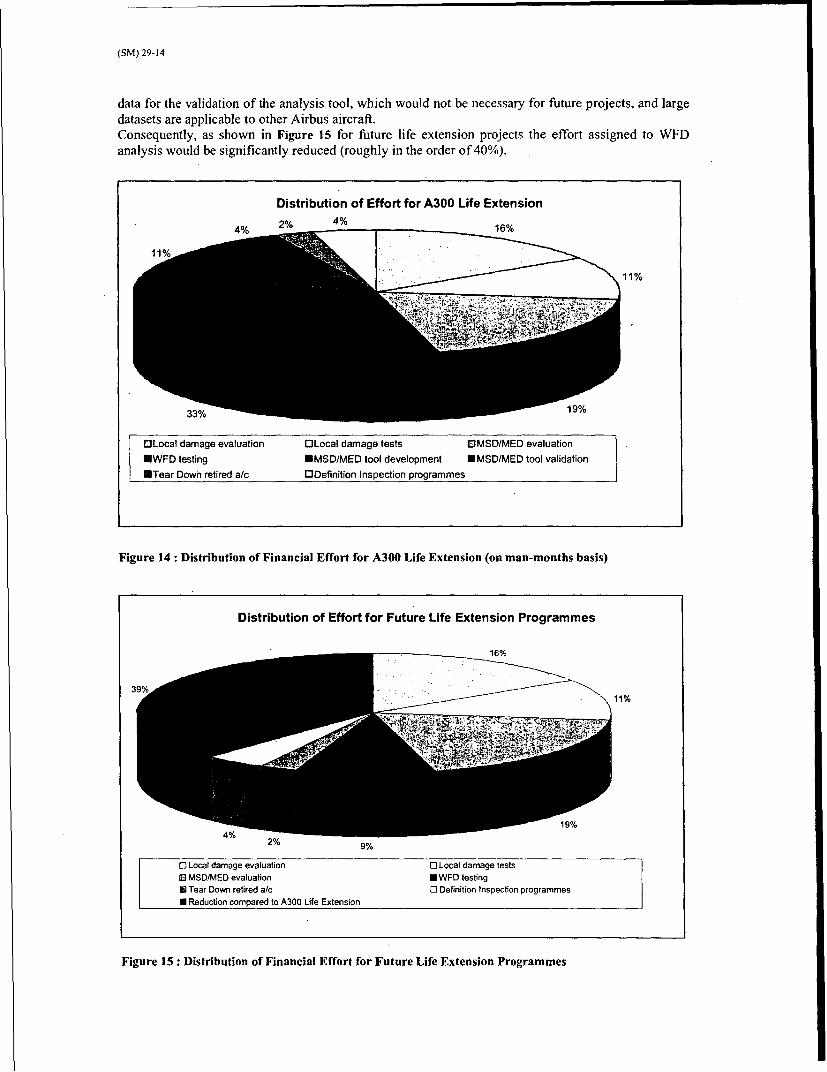
Figure 14 presents the distribution of financial effort spent for the major Full Life Extension activities(evaluation of repairs and definition of modifications not included).Approximately 30% of the total effort was required for the evaluation of local damage (including localdamage testing), while tear down and definition of inspection programmes only make up a small partof the total amount. It becomes obvious that the largest portion, almost 70% of the total effort, isassign to the evaluation of WFD with approximately half of that amount being consumed by WFDtesting. However, 15% of the total amount was required for the development and validation of theanalysis tool - this amount would not be counted for any follow-up life extension programme, e.g. forA3 10, A320 models. Furthermore, a large portion of the WFD testing was conducted in order to obtain
(SM) 29-14
data for the validation of the analysis tool, which would not be necessary for future projects, and largedatasets are applicable to other Airbus aircraft.Consequently, as shown in Figure 15 for future life extension projects the effort assigned to WFDanalysis would be significantly reduced (roughly in the order of 40%).
Distribution of Effort for A300 Life Extension4% 2% 4% 16%
111
OLocal damage evaluation 0 Local damage tests IMSD/MED evaluation*WFD testing IMSD/MED tool development *MSD/MED tool validationETear Down retired a/c ODefinition Inspection programmes
Figure 14: Distribution of Financial Effort for A300 Life Extension (on man-months basis)
Distribution of Effort for Future Life Extension Programmes
16%
4%4
9194% 2% 9%
O Local damage evaluation 0 Local damage tests0 MSD/MED evaluation 0 WFD testinga Tear Down retired a/c El Definition Inspection programmes0 Reduction compared to A300 Life Extension
Figure 15 : Distribution of Financial Effort for Future Life Extension Programmes

(SM) 29-15
References
[1] H.-J. SCHMIDT, B. SCHMIDT-BRANDECKER, H. TREY, 'Airbus A300 Fuselage Program forLife Extension and Widespread Fatigue Damage Evaluation', The Third Joint FAA/DOD/NASAConference on Aging Aircraft, Sept. 1999, Albuquerque, New Mexico, USA.
[2] J.McGUIRE & J.FOUCAULT, 'Recommendations for regulatory action to prevent widespreadfatigue damage in the commercial airplane fleet', Airworthiness Assurance Working Group,Transport Airplane and Engine Issues Group, Aviation Rulemaking Advisory Committee, FederalAviation Administration, Washington, D.C., USA (March 1999)
[3] ANON, 'Aircraft accident report, Aloha Airlines, flight 243,Boeing 737-200, N7371 1, near Maui,Hawaii, April 28, 1988', Report No. NTSB/AAR-89/03, National Transportation Safety Board,Washington, D.C., USA (June 1989)
[4] P. HORST, H. TREY, 'Structural Maintenance of Ageing Aircraft : SMAAC', Air & SpaceEurope, Vol 1, No. 5, 1999.
[5] R.G. FORMAN, Shivakumar, V., Mettu, R.S., Newman, J.C., "Fatigue Crack Growth ComputerProgramme NASGRO, JSC-22267B, Apr. 1999.
[6] J.A. HARTER, "AFGROW Users Guide and Technical Manual", AFRL-VA-WP-TR-1999-3016,Feb. 1999.
[7] J.C. NEWMAN, D.S. Darwicke, C.A. Bigelow, 'Finite Element Analysis and Fracture Simulationin Thin-sheet Aluminium Alloy', NASA TM 107662, August 1992, NASA Langley ResearchCenter, Hampton, V.A.
[8] P. WAWRZYNEK, A.R. Ingraffea, 'Interactive Finite Element Analysis of Fracture ProcessesAn Integrated Approach', Theoretical and Applied Facture Mechanics, v.8, pp. 137-150
[9] D. SWENSON, M. James, 'FRANC2D/L: A Crack Propagation Simulator for LayeredStructures' - User's Guide.


![Defense Technical Information Center Compilation Part Notice · Capabilities of Military Aircraft, ... des vehicules terrestres et des vehicules maritimes] To order the complete compilation](https://img.pdfslide.net/doc/110x75/5b2560117f8b9a26578b485b/defense-technical-information-center-compilation-part-notice-capabilities-of.jpg)


![Defense Technical Information Center Compilation Part … militaires: Consommation actuelle, questions et strategies pour des options elargies] ... Biologic Effects of Adrenal Hormones](https://img.pdfslide.net/doc/110x75/5ae3820a7f8b9a5b348d84ce/defense-technical-information-center-compilation-part-consommation-actuelle.jpg)


