Embed Size (px)
Citation preview
57JR EAST Technical Review-No.15
Special edition paperSpecial edition paper
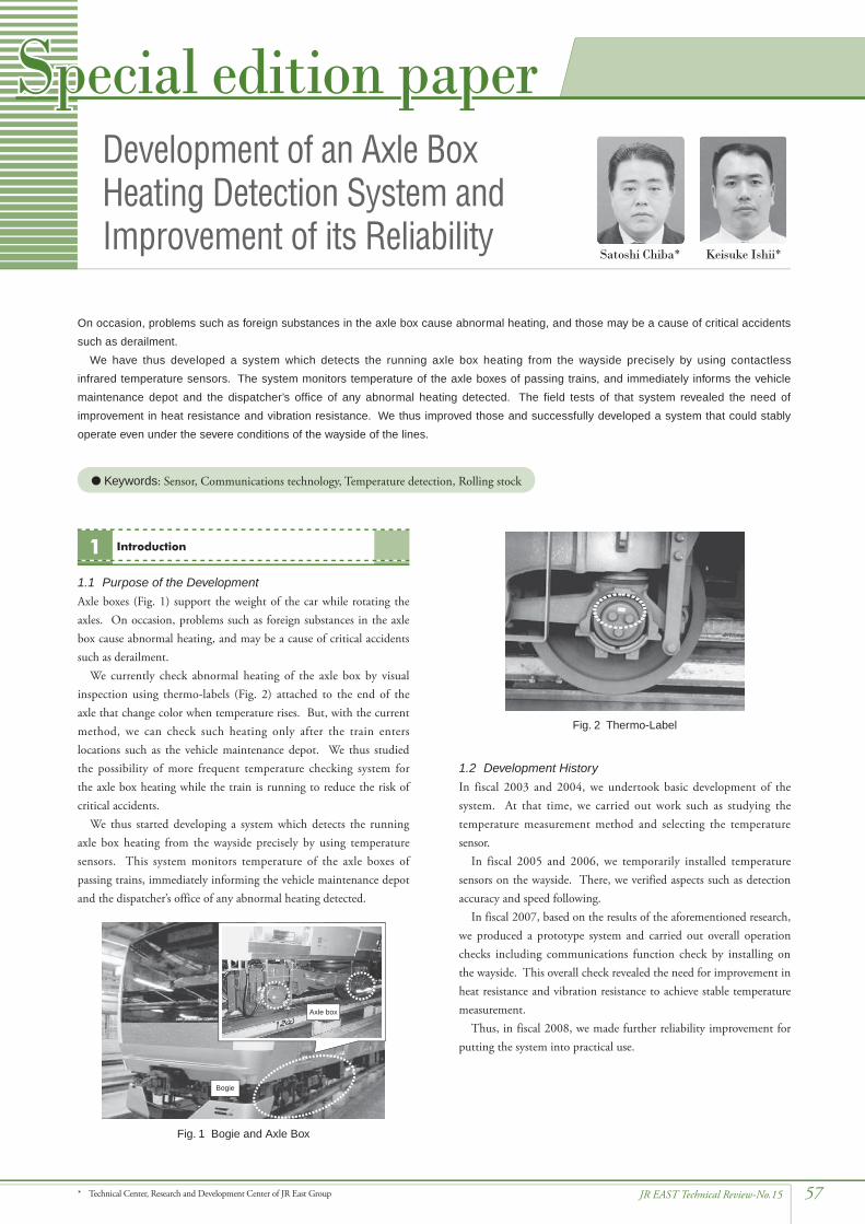
1.1 Purpose of the DevelopmentAxle boxes (Fig. 1) support the weight of the car while rotating the axles. On occasion, problems such as foreign substances in the axle box cause abnormal heating, and may be a cause of critical accidents such as derailment.
We currently check abnormal heating of the axle box by visual inspection using thermo-labels (Fig. 2) attached to the end of the axle that change color when temperature rises. But, with the current method, we can check such heating only after the train enters locations such as the vehicle maintenance depot. We thus studied the possibility of more frequent temperature checking system for the axle box heating while the train is running to reduce the risk of critical accidents.
We thus started developing a system which detects the running axle box heating from the wayside precisely by using temperature sensors. This system monitors temperature of the axle boxes of passing trains, immediately informing the vehicle maintenance depot and the dispatcher’s office of any abnormal heating detected.
Introduction1
1.2 Development HistoryIn fiscal 2003 and 2004, we undertook basic development of the system. At that time, we carried out work such as studying the temperature measurement method and selecting the temperature sensor.
In fiscal 2005 and 2006, we temporarily installed temperature sensors on the wayside. There, we verified aspects such as detection accuracy and speed following.
In fiscal 2007, based on the results of the aforementioned research, we produced a prototype system and carried out overall operation checks including communications function check by installing on the wayside. This overall check revealed the need for improvement in heat resistance and vibration resistance to achieve stable temperature measurement.
Thus, in fiscal 2008, we made further reliability improvement for putting the system into practical use.
Development of an Axle Box Heating Detection System and Improvement of its Reliability
On occasion, problems such as foreign substances in the axle box cause abnormal heating, and those may be a cause of critical accidents such as derailment.
We have thus developed a system which detects the running axle box heating from the wayside precisely by using contactless infrared temperature sensors. The system monitors temperature of the axle boxes of passing trains, and immediately informs the vehicle maintenance depot and the dispatcher’s office of any abnormal heating detected. The field tests of that system revealed the need of improvement in heat resistance and vibration resistance. We thus improved those and successfully developed a system that could stably operate even under the severe conditions of the wayside of the lines.
l Keywords: Sensor, Communications technology, Temperature detection, Rolling stock
* Technical Center, Research and Development Center of JR East Group
Keisuke Ishii*Satoshi Chiba*
Axle box
Bogie
Fig. 1 Bogie and Axle Box
Fig. 2 Thermo-Label

58 JR EAST Technical Review-No.15
Special edition paper
Here we will introduce the function and feature of individual devices.
3.2 Temperature SensorThe temperature sensors used are infrared radiation thermometers. They focus the energy radiated from the target using a lens and make contactless temperature measurement of that temperature. For this system, we adopted a highly directional temperature sensor that can capture the target within a measurement diameter of 24 mm or less at a measurement distance of 1,000 mm. With that sensor, the system can accurately measure the axle box temperature under the floor of the cars of a running train. When the sensor is installed just to the side of the bogie, it cannot make accurate measurement of the axle box temperature because the tachometer generator at the end of the axle is located between the sensor and the axle box. So, in this system, the sensor measures the temperature of the bottom surface of the axle box obliquely from below (Fig. 5).
To protect it against flying debris, the sensor is accommodated in a housing (Fig. 6). The housing also has a dust-proof structure to protect the infrared receiver lens from dust (Fig. 7). That structure is divided into two chambers, and they have many “labyrinth rings” inside. When pumping air is ventilated to “labyrinth rings” from the processor through the air pipe (Fig. 5 and 6), a localized vortex is caused. By this mechanism, the infrared receiver lens is protected from dust.
Under the floor of a train car, wheels and some devices sometimes have a relatively high temperature even in normal use. Therefore, in this system, we decided to adopt a method to identify the positions of the center of each wheel based on signals from the wheel detector that checks passing trains. And from that information, we identify the position of the axle box of the passing train.
This method allows us to detect only abnormal heating of the axle box, avoiding accidentally detecting normal heating of the wheels and some devices (Fig. 3). Next, distinguished peak temperature is checked with the train set number of the passing train that the ID antenna receives. As the result, the system can check abnormal heating of each axle box of each car of the passing trains.
If abnormal heating is detected, the system immediately informs the terminal units in the vehicle maintenance depot and the dispatcher’s office of that via a dedicated line, and the alarm units there give an alert and light up an indicator lamp. Just as the thermo-labels do, the system judges the temperature of the axle box more than 120°C to be abnormal.
3.1 System ConfigurationIndividual devices are installed on the wayside and in the vehicle maintenance depot and dispatcher’s office as follows (Fig. 4).(1) On the wayside Temperature sensor, Wheel detector, ID antenna, Processor(2) In the vehicle maintenance depot and the dispatcher’s office Terminal, Alarm unit
Peak values within the red marks are recorded as the axle box temperature.
Peak values
Fig. 3 Relation Between the Location of the Bogie and Temperature Waveform of the Axle Box
Connection of the air pipe from the processor to the dust-proof structure
Fig. 5 Setup of Housing that Holds the Temperature Sensor
Dust-proof structure
Air pipe from processorand air vent
Temperaturesensor
Fig. 6 Dust-Proof Structure in the Housing and Temperature Sensor
[Along the track][Vehicle maintenance depot]Wheel detector
Terminal
Alarm
[Dispatcher’s office]
Terminal
Alarm
ID antenna
Temperature sensor Processor
[Dedicated line]
Fig. 4 System Configuration
System Configuration and Functions/Features of Individual Devices3
System Overview2

59JR EAST Technical Review-No.15
Special edition paper
3.3 Wheel DetectorWe set six wheel detectors in three opposing pairs on both sides of the inside of the rails at intervals of about 3 m (Fig. 8). Those output a detection signal to the processor at passing of a wheel to detect the position of the axle box. They also work as a power-on switch for the system to make detection only at passing of trains.
3.4 ID AntennaThe ID antenna is installed on the wayside to obtain data from the onboard ID plate. When a train passes, the antenna obtains data such as the train set number, the depot that the train set belongs to and the car type (Fig. 9).
3.5 ProcessorThe processor performs a variety of operations based on data of the temperature sensor, wheel detector and ID plate. Those include checking passing train speed, calculating the center of the wheels, identifying the peak value of the temperature data of the axle box, collating that peak value with the position of the axle box of the passing train and checking for abnormal heating of each axle box of each car of the trains. If the processor detects the axle box temperature to be more than 120°C, an alarm signal is sent immediately via a dedicated line to the terminal units in the vehicle maintenance depot and the dispatcher’s office (Fig. 10). The processor further has the aforementioned ventilation device for the dust-proof structure of the temperature sensor.
Data obtained is also saved in the processor. The processor sends the peak temperature values of the axle boxes of the trains of the day to the vehicle maintenance depot daily at night.
3.6 Terminal Unit and Alarm UnitThe terminal units in the vehicle maintenance depot and the dispatcher’s office are usually standing by with the power on. When the terminal receives information of abnormal heating of an axle box, it displays on the screen the date and time, train set number, train speed and temperature of each axle box. The part of the axle box with abnormal heating is indicated in red. The terminal unit also shows a message indicating the abnormal heating (Fig. 11) and the alarm unit gives an alert and lights up an indicator lamp.
Labyrinth seal rings
Air vent
Fig. 7 Dust-Proof Structure
Fig. 8 Installation and Appearance of the Wheel Detector
ID antenna
Housing for temperature sensor
Fig. 9 ID Antenna
Measurement resultsfor a car of a train Part with
abnormal heating
Fig. 11 Display in Abnormal Heating of the Axle Box
Ventilation device
Fig. 10 Processor and Ventilation Device

60 JR EAST Technical Review-No.15
Special edition paper
keep the temperature in the housing under the 45°C that is sufficient for use of the temperature sensor.
5.2 Vibration ResistanceWe found that passing trains sometimes caused vibration larger than that allowed in the specs of the temperature sensor. We thus added a damper and anti-vibration gel to the mount of the temperature sensor (Fig. 14) and checked the effectiveness in bench tests and the field tests. The test results showed that those could sufficiently keep vibration value.
5.3 Field Tests IIIn fiscal 2008, we installed the system on the wayside of two lines after the improvement in heat resistance and vibration resistance, and we confirmed good results as previously mentioned. We also reviewed the conditions of installation points and checked maintainability and cost performance.
As described above, we were able to develop an axle box temperature detection system that could demonstrate stable operation even in the severe conditions near commercial lines. We will gradually introduce a production model of that system to major conventional lines in the Tokyo metropolitan area.
Coolers(on the right and left sides of the housing)
Thermal barrier coating(to the all surfaces of the housing)
Fig. 13 Improvement Details (Heat Resistance)
Damper
Anti-vibration gel
Temperaturesensor
Fig. 14 Improvement Details (Quake Resistance)
4.1 Overall Operation CheckOn the assumption that the system will be introduced to conventional lines in the Tokyo metropolitan area, we installed the prototype systems near Higashi-Totsuka station on the Yokosuka line (outbound line) and Akabane station on the Keihin Tohoku line (northbound line) and monitored the temperature of the axle boxes of the passing trains to verify system operation on commercial lines (Fig. 12). The prototype generally showed good results in terms of detection and information flow. However, the results showed that the system needs to be further improved in terms of heat resistance and vibration resistance.
4.2 Operation Check in Abnormal HeatingIn the overall operation check, no abnormal heating of the axle box occurred with trains in commercial service. So, we carried out another test to check the operation flow from detection of abnormal heating by the temperature sensor, through determining abnormal heating and informing to the terminal units by the processor, to alarm units giving an alert. In this check, we ran a test train at actual operating speeds with a heater attached to the side of a car body that simulated abnormal heating of the axle box. The system successfully detected heat at every train speed, and we confirmed that the system operates properly.
The overall operation check showed that the system required further improvement terms heat resistance and vibration resistance for practical use, so we carried out that improvement. Details are as follows.
5.1 Heat ResistanceThe field tests revealed that the temperature in the housing became quite high when the ambient temperature in midsummer is high, and we are concerned about adverse effects on the temperature sensor. We thus added coolers and thermal barrier coating to the housing (Fig. 13) and checked the effectiveness in bench tests and in the field temperature tests. The test results showed that those measures could
Omiya
Yokohama
Urawa depotAkabane station
Higashi-Totsukastation
Tokyo generaldispatcher’s office
Temperature sensor installation point
Terminal unit or other device installation point
Kamakura vehicle maintenance depot
Fig. 12 Test Points
Field Test I4
Improvement5 Conclusion6
Reference:1) Satoshi Chiba: “Development of the TC-Type Axle Box
Temperature Detection System”, JR East Technical Review No. 21, 2007