Embed Size (px)
Citation preview

Center for proton therapy - PSI
15.06.2011PSI,
Gantry 2, the next generation gantry of PSI:
a new system for promoting pencil beam scanning as a universal
beam delivery technique
IOP Half-Day Meeting on Hadron Therapy
Friday 10 June 2011
Manchester
Pedroni Eros
Paul Scherrer Institute - Villigen PSI, Switzerland
15.06.2011PSI, Page 2
Layout of the presentation
–Gantry 1 experience–Facility expansion at PSI - new SC cyclotron
–The new Gantry 2 of PSI
–Layout
–Beam optics and beam size
–Energy variations with the beam
–Sweeper magnets calibration
–Advanced beam scanning techniques
–Possible future clinical use of Gantry 2
–Scanning as a universal beam delievery

15.06.2011PSI, Page 3
Early 90's …
GANTRY 1
USED FOR PATIENT TREATMENTS SINCE 1996
GOAL in 1989
SHOW THE BASIC FEASIBILITY OF PENCIL BEAM SCANNING
15.06.2011PSI, Page 4
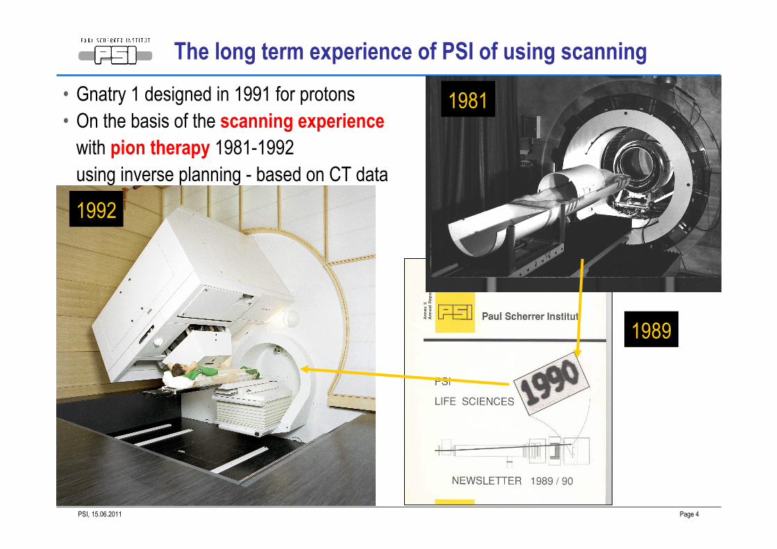
The long term experience of PSI of using scanning
Gantry 1
• Gnatry 1 designed in 1991 for protons
• On the basis of the scanning experience
with pion therapy 1981-1992
using inverse planning - based on CT data
1981
1992
1989

15.06.2011PSI, Page 5
• Upstream scanning
• Magnetic scanning started before the last bending magnet
• Eccentric mounting of patient table on the gantry front wheel
(with counter-rotation)
• Gantry radius reduced to 2 m
• Still the smallest proton gantry in the world
System characteristics of Gantry 1
α rotation
φ rotationβ rotation
15.06.2011PSI, Page 6
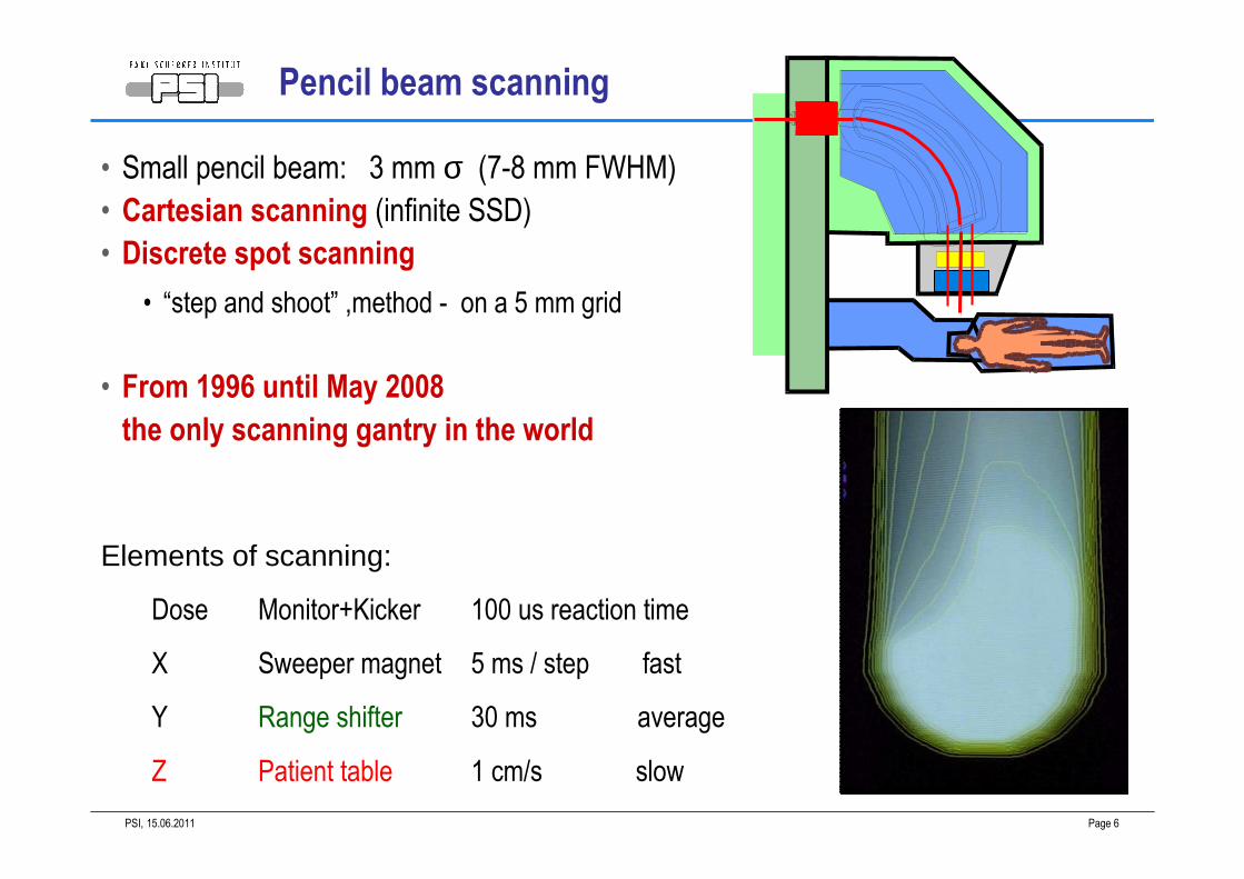
X Sweeper magnet 5 ms / step fast
Y Range shifter 30 ms average
Z Patient table 1 cm/s slow
Dose Monitor+Kicker 100 us reaction time
Elements of scanning:
Pencil beam scanning
• Small pencil beam: 3 mm σ (7-8 mm FWHM)
• Cartesian scanning (infinite SSD)
• Discrete spot scanning
• “step and shoot” ,method - on a 5 mm grid
• From 1996 until May 2008
the only scanning gantry in the world

15.06.2011PSI, Page 7
Clinical use of GANTRY 1
• In use since1996
• Full fractionation ~30 fractions
• Treatments 8:00 16:00
• Max 19 patients/day (2.5 per hour)
• 2.8 fields/fractions in average
• 1/3 of patients are children
• Under anesthesia
• 1/3 of treatments are IMPT
• Weak points of Gantry 1
• Table motion is part of scanning
• Not possible to use collimators
• Not possible to apply repainting
• We treat only
• non moving targets!
Courtesy of B. Timmermann
15.06.2011PSI, Page 8
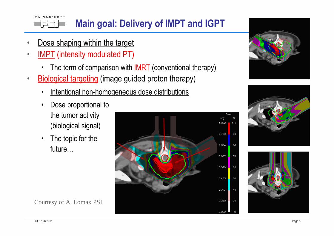
Main goal: Delivery of IMPT and IGPT
• Dose shaping within the target
• IMPT (intensity modulated PT)
• The term of comparison with IMRT (conventional therapy)
• Biological targeting (image guided proton therapy)
• Intentional non-homogeneous dose distributions
• Dose proportional to
the tumor activity
(biological signal)
• The topic for the
future…
Courtesy of A. Lomax PSI
15.06.2011PSI, Page 9
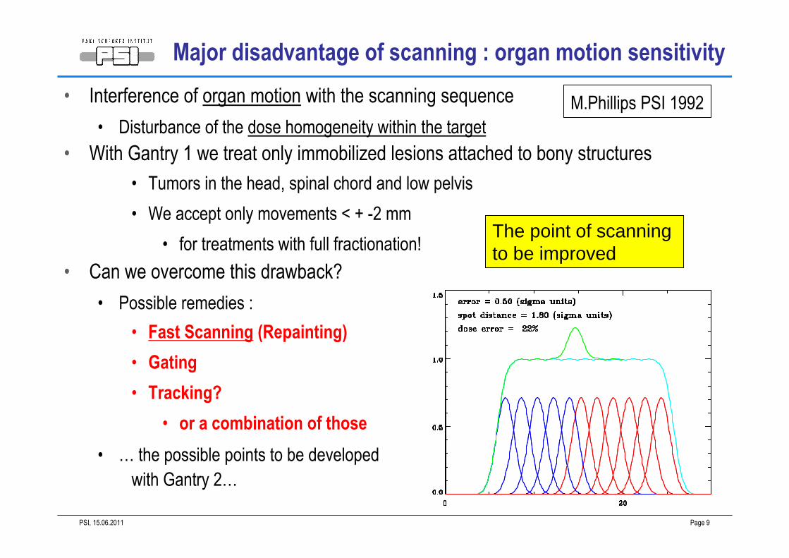
Major disadvantage of scanning : organ motion sensitivity
• Interference of organ motion with the scanning sequence
• Disturbance of the dose homogeneity within the target
• With Gantry 1 we treat only immobilized lesions attached to bony structures
• Tumors in the head, spinal chord and low pelvis
• We accept only movements < + -2 mm
• for treatments with full fractionation!
• Can we overcome this drawback?
• Possible remedies :
• Fast Scanning (Repainting)
• Gating
• Tracking?
• or a combination of those
• … the possible points to be developed
with Gantry 2…
The point of scanning to be improved
M.Phillips PSI 1992
15.06.2011PSI, Page 10
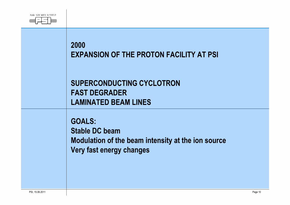
2000
EXPANSION OF THE PROTON FACILITY AT PSI
SUPERCONDUCTING CYCLOTRON
FAST DEGRADER
LAMINATED BEAM LINES
GOALS:
Stable DC beam
Modulation of the beam intensity at the ion source
Very fast energy changes
15.06.2011PSI, Page 11
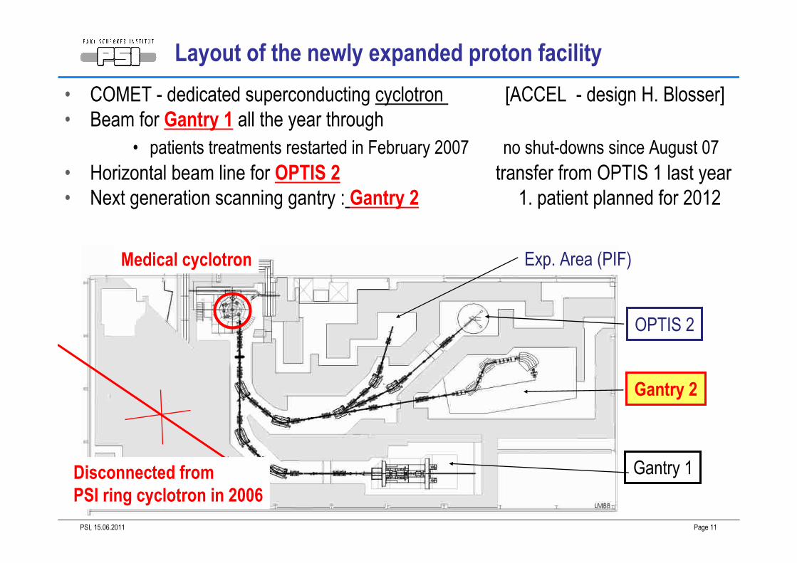
Layout of the newly expanded proton facility
• COMET - dedicated superconducting cyclotron [ACCEL - design H. Blosser]
• Beam for Gantry 1 all the year through
• patients treatments restarted in February 2007 no shut-downs since August 07
• Horizontal beam line for OPTIS 2 transfer from OPTIS 1 last year
• Next generation scanning gantry : Gantry 2 1. patient planned for 2012
Gantry 2
Gantry 1
OPTIS 2
Exp. Area (PIF)
Disconnected from
PSI ring cyclotron in 2006
Medical cyclotron

15.06.2011PSI, Page 12
Facility specifications were derived for the new Gantry 2
• Super-conducting cyclotron
• Very stable beam at the ion source
• Aiming at 2-3% at the 100-200 µs scale• Deflector plate in the first orbit
• Dynamic control of the beam intensity
• 100-200 µs time scale• Fast degrader (moving carbon wedges)
• Continuous choice of the beam energy
• Beam line with laminated magnets
• Providing fast changes of beam energy
15.06.2011PSI, Page 13
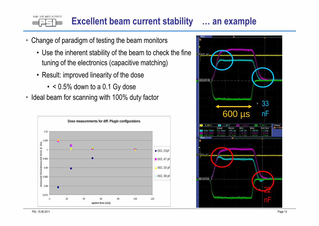
Excellent beam current stability … an example
• Change of paradigm of testing the beam monitors
• Use the inherent stability of the beam to check the fine
tuning of the electronics (capacitive matching)
• Result: improved linearity of the dose
• < 0.5% down to a 0.1 Gy dose
• Ideal beam for scanning with 100% duty factor
Dose measurements for diff. Plugin configurations
0.975
0.98
0.985
0.99
0.995
1
1.005
1.01
0 20 40 60 80 100 120
applied Dose [cGy]
mea
sure
d D
ose
/mea
sure
d D
ose
@ 1
Gy
ISO, 22pf
ISO, 47 pf
ISO, 33 pf
ISO, 39 pf
• 22
nF
• 33
nF600 µs
15.06.2011PSI, Page 14
2005
A NEW PSI GANTRY - GANTRY 2
MAIN GOAL
DEVELOP FURTHER SCANNING
TO BECOME A UNIVERSAL BEAM DELIVERY TECHNIQUE
15.06.2011PSI, Page 15
GANTRY 2
TOPIC 1: INNOVATIVE GANTRY LAYOUT
READINESS FOR
IMAGE GUIDED PROTON THERAPY
VERY EFFICIENT PATIENT HANDLING
15.06.2011PSI, Page 16
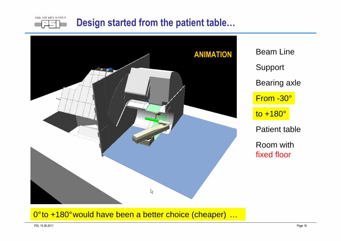
Beam Line
Support
Bearing axle
From -30°
to +180°
Patient table
Room withfixed floor
0°to +180°would have been a better choice (cheaper) …
Design started from the patient table…
ANIMATION
15.06.2011PSI, Page 17
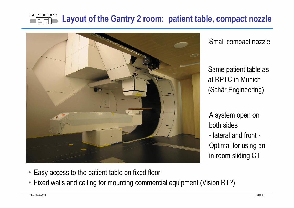
Layout of the Gantry 2 room: patient table, compact nozzle
• Easy access to the patient table on fixed floor
• Fixed walls and ceiling for mounting commercial equipment (Vision RT?)
A system open on
both sides
- lateral and front -
Optimal for using an
in-room sliding CT
Small compact nozzle
Same patient table as
at RPTC in Munich
(Schär Engineering)
15.06.2011PSI, Page 18
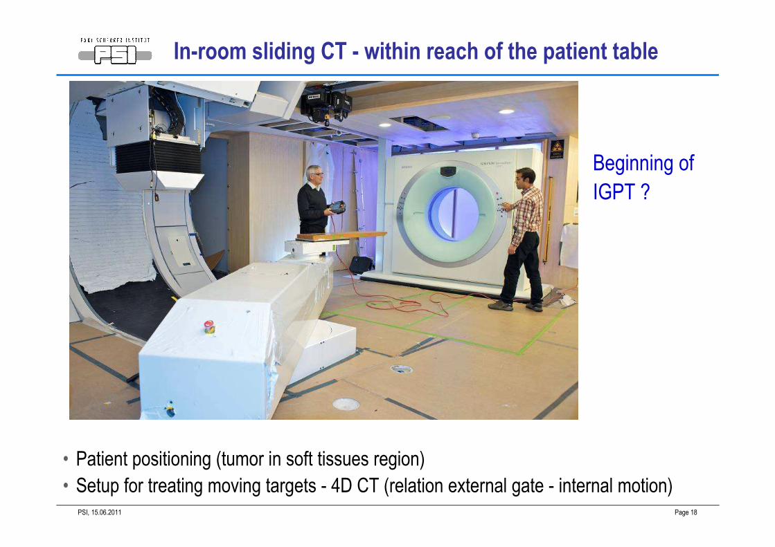
In-room sliding CT - within reach of the patient table
• Patient positioning (tumor in soft tissues region)
• Setup for treating moving targets - 4D CT (relation external gate - internal motion)
Beginning of
IGPT ?

15.06.2011PSI, Page 19
a) compact gantry b) long throw gantry
Sweepers
X rays tubeProton beam
Bending
magnet
nozzle
Yoke hole
Patient
Imager
Sweeper
or
Scatterer
Collimator
• BEV imaging - equivalent to portal imaging with photons• Very large field-of-view (26 cm x 16 cm)
• not masked by equipment or collimators in the beam path• QA control of gating and tracking
(scanning + pulsed X-rays)• Fluoroscopy mode
• Beam guidance?
BEV X-ray - synchronized with proton beam delivery
UPSTREAM SCANNING
Bend and scan
Scan and bend
IGPT
15.06.2011PSI, Page 20
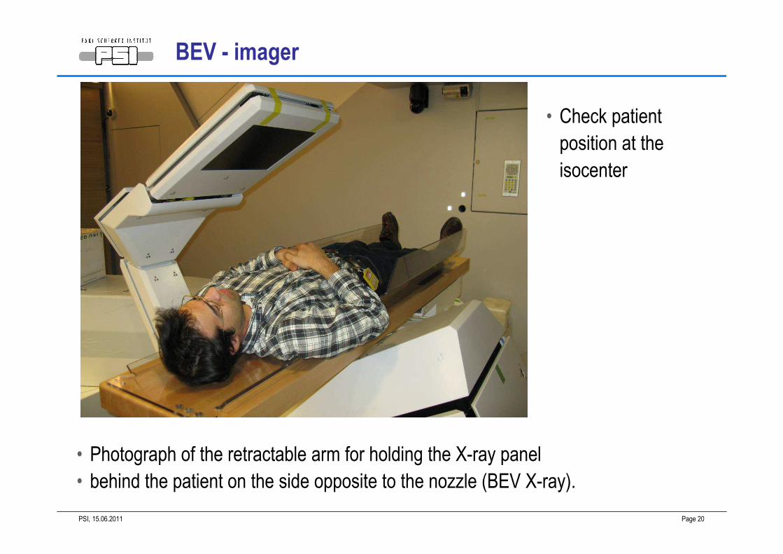
BEV - imager
• Photograph of the retractable arm for holding the X-ray panel
• behind the patient on the side opposite to the nozzle (BEV X-ray).
• Check patient
position at the
isocenter
15.06.2011PSI, Page 21
GANTRY 2
TOPIC 2: PENCIL BEAM AND BEAM OPTICS
GOALS:
SMALL PENCIL BEAM FOR PRECISION THERAPY
PARALLELISM OF SCANNING
15.06.2011PSI, Page 22
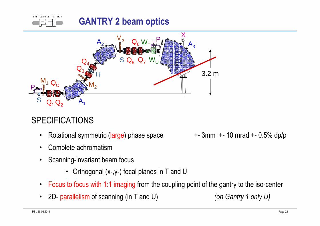
GANTRY 2 beam optics
• Rotational symmetric (large) phase space +- 3mm +- 10 mrad +- 0.5% dp/p
• Complete achromatism
• Scanning-invariant beam focus
• Orthogonal (x-,y-) focal planes in T and U
• Focus to focus with 1:1 imaging from the coupling point of the gantry to the iso-center
• 2D- parallelism of scanning (in T and U) (on Gantry 1 only U)
SPECIFICATIONS
Q1
Q3
Q4Q5
Q6
Q7
A1
A2 A3
WU
WT
M1 M2
M3 P
P
S
S
H 3.2 m
Q2
QC
X
15.06.2011PSI, Page 23
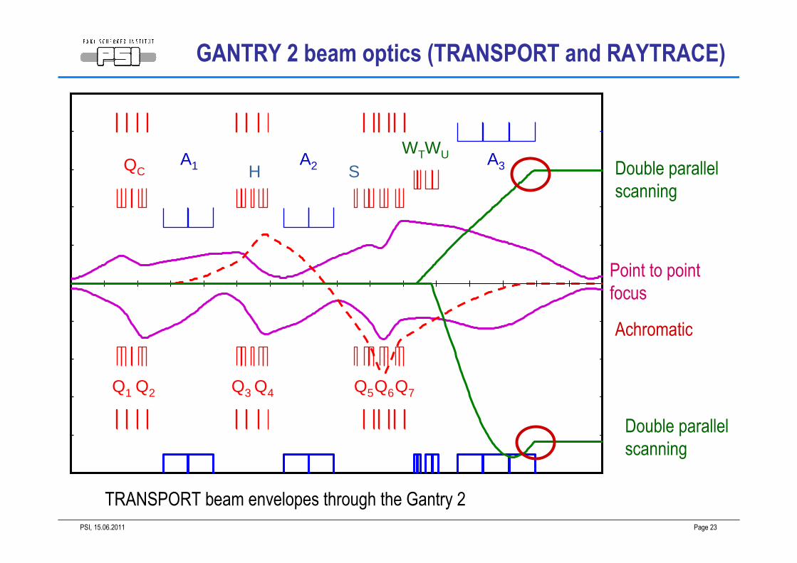
TRANSPORT beam envelopes through the Gantry 2
A3A2A1
Q2Q1
QC
Q3 Q4 Q5Q6Q7
WTWU
H S Double parallel
scanning
Point to point
focus
Achromatic
Double parallel
scanning
GANTRY 2 beam optics (TRANSPORT and RAYTRACE)
15.06.2011PSI, Page 24
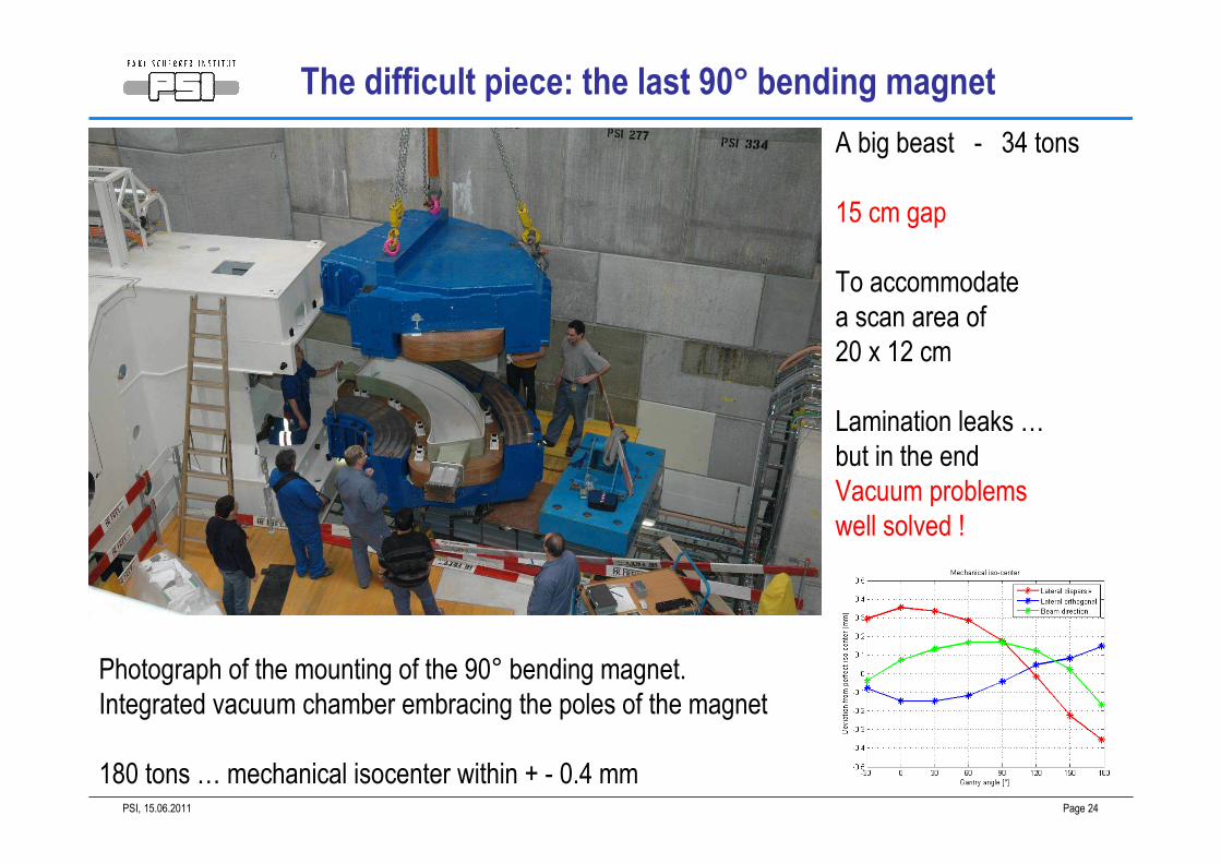
Photograph of the mounting of the 90° bending magnet.
Integrated vacuum chamber embracing the poles of the magnet
180 tons … mechanical isocenter within + - 0.4 mm
A big beast - 34 tons
15 cm gap
To accommodate
a scan area of
20 x 12 cm
Lamination leaks …
but in the end
Vacuum problems
well solved !
The difficult piece: the last 90° bending magnet
15.06.2011PSI, Page 25
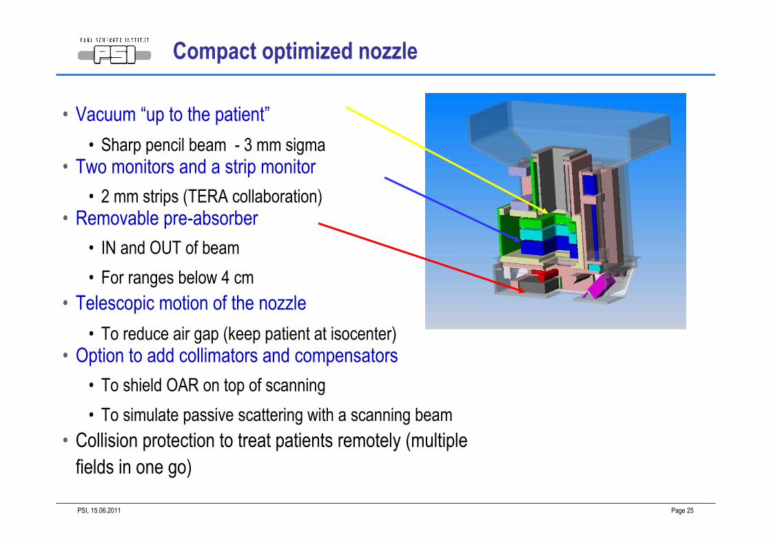
• Vacuum “up to the patient”
• Sharp pencil beam - 3 mm sigma
• Two monitors and a strip monitor
• 2 mm strips (TERA collaboration)
• Removable pre-absorber
• IN and OUT of beam
• For ranges below 4 cm
• Telescopic motion of the nozzle
• To reduce air gap (keep patient at isocenter)
• Option to add collimators and compensators
• To shield OAR on top of scanning
• To simulate passive scattering with a scanning beam
• Collision protection to treat patients remotely (multiple
fields in one go)
Compact optimized nozzle
15.06.2011PSI, Page 26
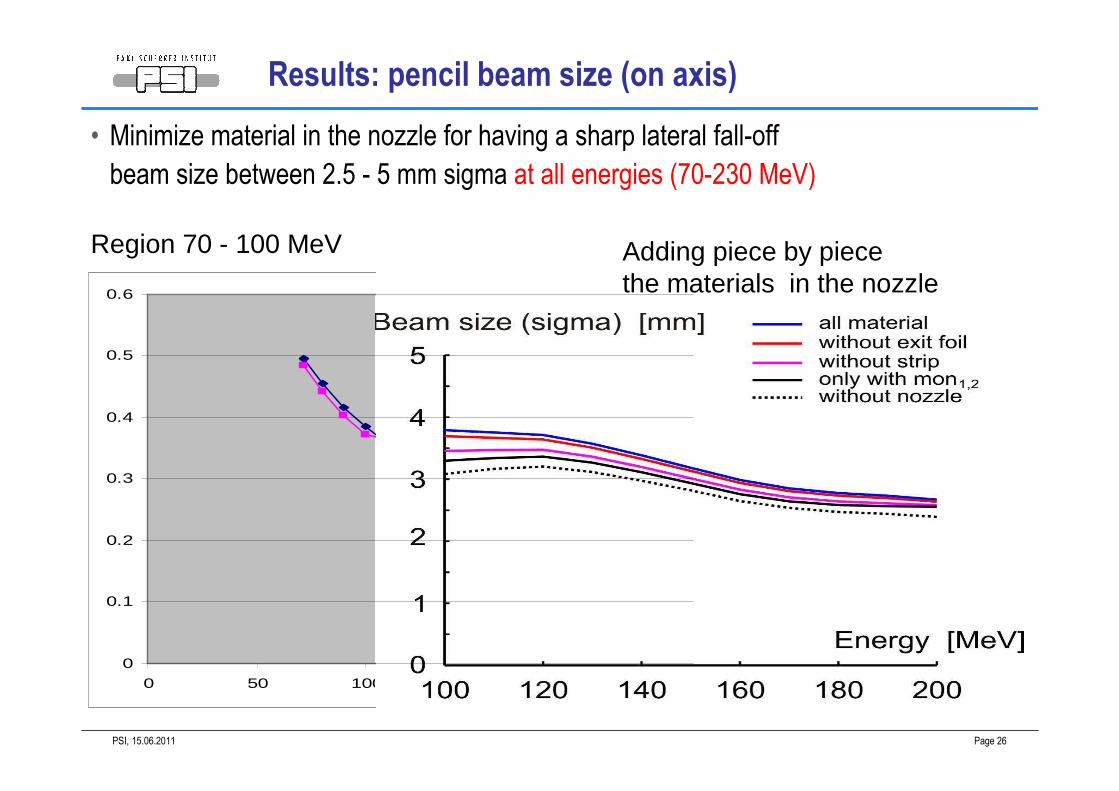
Results: pencil beam size (on axis)
• Minimize material in the nozzle for having a sharp lateral fall-off
beam size between 2.5 - 5 mm sigma at all energies (70-230 MeV)
0
0.1
0.2
0.3
0.4
0.5
0.6
0 50 100
Adding piece by piecethe materials in the nozzle
Region 70 - 100 MeV
15.06.2011PSI, Page 27
GANTRY 2
TOPIC 3 :
ENERGY VARIATIONS WITH THE BEAM LINE
COMPENSATED INTENSITY-ENERGY LOSSES
VERY FAST ENERGY CHANGES
15.06.2011PSI, Page 28
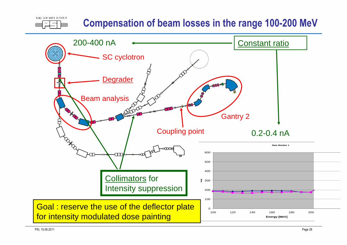
SC cyclotron
Degrader
Beam analysis
Collimators forIntensity suppression
Coupling point
Gantry 2
Compensation of beam losses in the range 100-200 MeV
Rate Monitor 1
0
100
200
300
400
500
600
100 120 140 160 180 200
Energy [MeV]
kHz
200-400 nA
0.2-0.4 nA
Constant ratio
Goal : reserve the use of the deflector plate for intensity modulated dose painting
15.06.2011PSI, Page 29
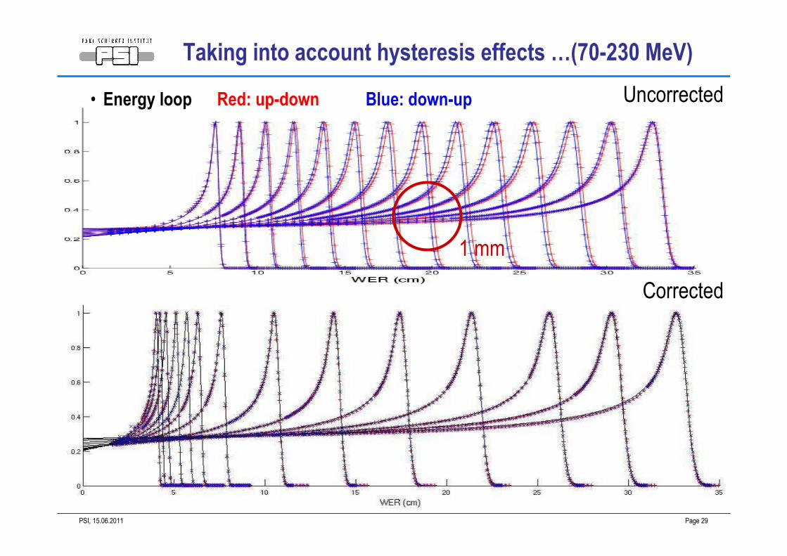
• Energy loop Red: up-down Blue: down-up
Taking into account hysteresis effects …(70-230 MeV)
Uncorrected
Corrected
1 mm
15.06.2011PSI, Page 30
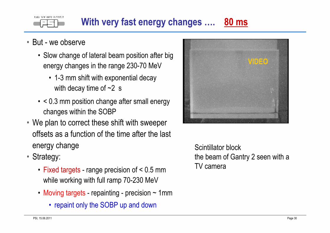
Scintillator block
the beam of Gantry 2 seen with a
TV camera
• But - we observe
• Slow change of lateral beam position after big
energy changes in the range 230-70 MeV
• 1-3 mm shift with exponential decay
with decay time of ~2 s
• < 0.3 mm position change after small energy
changes within the SOBP
• We plan to correct these shift with sweeper
offsets as a function of the time after the last
energy change
• Strategy:
• Fixed targets - range precision of < 0.5 mm
while working with full ramp 70-230 MeV
• Moving targets - repainting - precision ~ 1mm
• repaint only the SOBP up and down
With very fast energy changes …. 80 ms
VIDEO
15.06.2011PSI, Page 31
GANTRY 2
TOPIC 4 : SWEEPER MAGNETS
COMMISSIONING ISSUES
NON LINEARITIES OF THE SWEEPERS
15.06.2011PSI, Page 32
−15 −10 −5 0 5 10 15−8
−6
−4
−2
0
2
4
6
8210 MeV
U (cm)
T (
cm)
−15 −10 −5 0 5 10 15−8
−6
−4
−2
0
2
4
6
8150 MeV
U (cm)
T (
cm)
−15 −10 −5 0 5 10 15−8
−6
−4
−2
0
2
4
6
880 MeV
U (cm)
T (
cm)
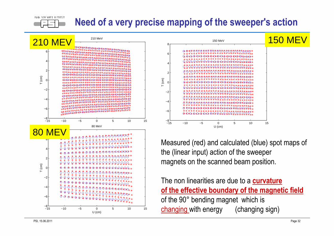
Measured (red) and calculated (blue) spot maps of
the (linear input) action of the sweeper
magnets on the scanned beam position.
The non linearities are due to a curvature
of the effective boundary of the magnetic field
of the 90° bending magnet which is
changing with energy (changing sign)
210 MEV
80 MEV
150 MEV
Need of a very precise mapping of the sweeper's action
15.06.2011PSI, Page 33
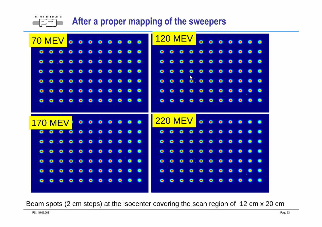
Beam spots (2 cm steps) at the isocenter covering the scan region of 12 cm x 20 cm
70 MEV 120 MEV
170 MEV 220 MEV
After a proper mapping of the sweepers
15.06.2011PSI, Page 34
GANTRY 2
Topic 5 : the main goal of Gantry 2
NEW ADVANCED BEAM DELIVERY TECHNIQUES
TO PROMOTE SCANNING AS A UNIVERSAL BEAM DELIVERY
TECHNIQUE
15.06.2011PSI, Page 35
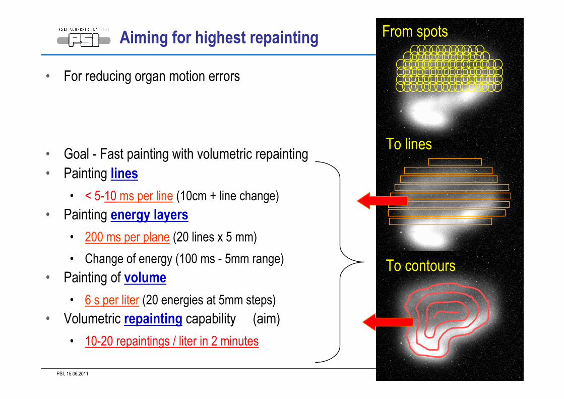
• For reducing organ motion errors
• Goal - Fast painting with volumetric repainting
• Painting lines
• < 5-10 ms per line (10cm + line change)
• Painting energy layers
• 200 ms per plane (20 lines x 5 mm)
• Change of energy (100 ms - 5mm range)
• Painting of volume
• 6 s per liter (20 energies at 5mm steps)
• Volumetric repainting capability (aim)
• 10-20 repaintings / liter in 2 minutes
Aiming for highest repainting From spots
To lines
To contours
15.06.2011PSI, Page 36
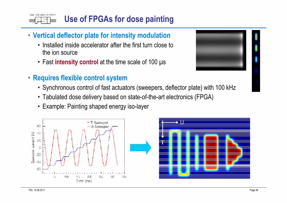
Use of FPGAs for dose painting
• Vertical deflector plate for intensity modulation
• Installed inside accelerator after the first turn close to the ion source
• Fast intensity control at the time scale of 100 µs
• Requires flexible control system
• Synchronous control of fast actuators (sweepers, deflector plate) with 100 kHz
• Tabulated dose delivery based on state-of-the-art electronics (FPGA)
• Example: Painting shaped energy iso-layer
15.06.2011PSI, Page 37
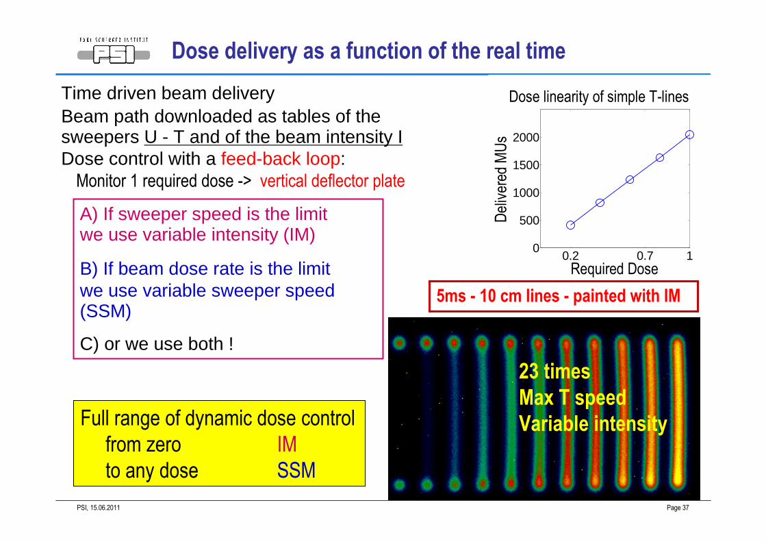
Time driven beam delivery Beam path downloaded as tables of the sweepers U - T and of the beam intensity IDose control with a feed-back loop:Monitor 1 required dose -> vertical deflector plate
A) If sweeper speed is the limitwe use variable intensity (IM)
B) If beam dose rate is the limitwe use variable sweeper speed (SSM)
C) or we use both !
Dose delivery as a function of the real time
Full range of dynamic dose control
from zero IM
to any dose SSM
23 times
Max T speed
Variable intensity
0.2 0.7 10
500
1000
1500
2000
Required Dose
Delivered MUs
Dose linearity of simple T-lines
5ms - 10 cm lines - painted with IM
15.06.2011PSI, Page 38
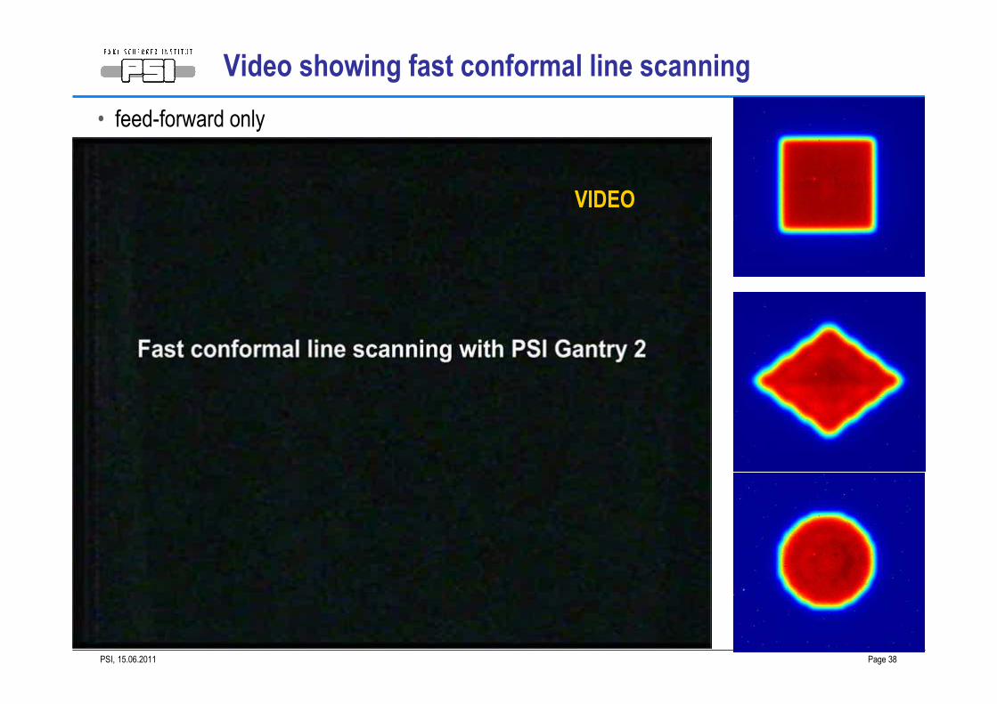
Video showing fast conformal line scanning
• feed-forward only
VIDEO
15.06.2011PSI, Page 39
GANTRY 2
POSSIBLE CLINICAL USE OF GANTRY 2
GOAL:
PROMOTE SCANNING
AS A UNIVERSAL BEAM DELIVERY TECHNIQUE
make scattering obsolete
15.06.2011PSI, Page 40
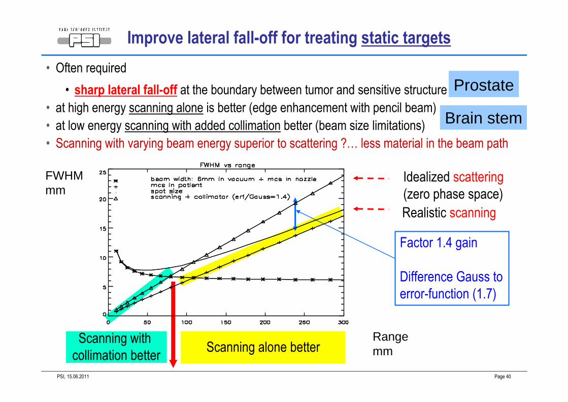
• Often required
• sharp lateral fall-off at the boundary between tumor and sensitive structure
• at high energy scanning alone is better (edge enhancement with pencil beam)
• at low energy scanning with added collimation better (beam size limitations)
• Scanning with varying beam energy superior to scattering ?… less material in the beam path
Factor 1.4 gain
Difference Gauss to
error-function (1.7)
Scanning with
collimation betterScanning alone better
Idealized scattering
(zero phase space)
Realistic scanning
FWHMmm
Rangemm
Prostate
Brain stem
Improve lateral fall-off for treating static targets
15.06.2011PSI, Page 41
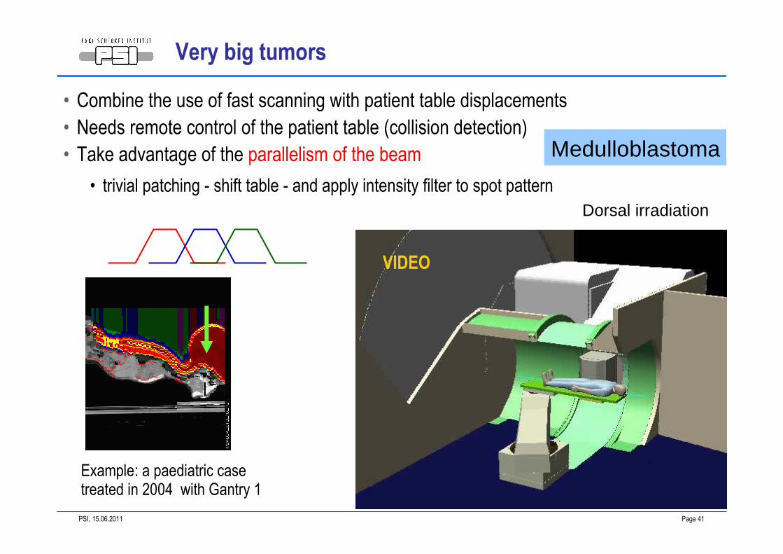
Example: a paediatric case treated in 2004 with Gantry 1
Dorsal irradiation
Very big tumors
• Combine the use of fast scanning with patient table displacements
• Needs remote control of the patient table (collision detection)
• Take advantage of the parallelism of the beam
• trivial patching - shift table - and apply intensity filter to spot pattern
Medulloblastoma
VIDEO
15.06.2011PSI, Page 42
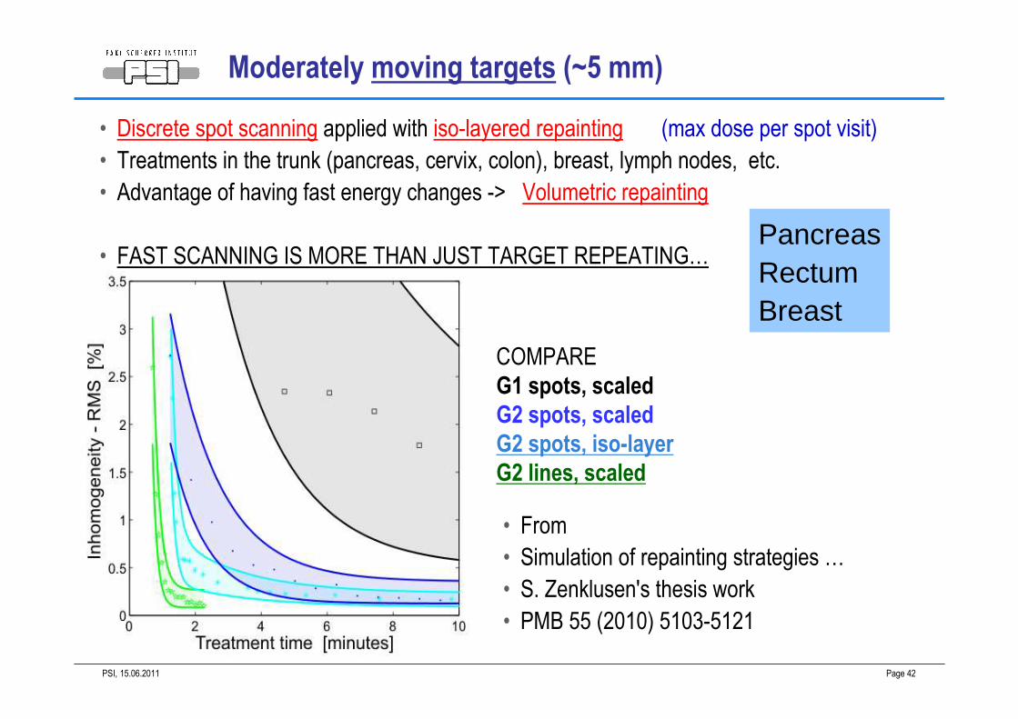
• From
• Simulation of repainting strategies …
• S. Zenklusen's thesis work
• PMB 55 (2010) 5103-5121
COMPARE
G1 spots, scaled
G2 spots, scaled
G2 spots, iso-layer
G2 lines, scaled
PancreasRectumBreast
• Discrete spot scanning applied with iso-layered repainting (max dose per spot visit)
• Treatments in the trunk (pancreas, cervix, colon), breast, lymph nodes, etc.
• Advantage of having fast energy changes -> Volumetric repainting
• FAST SCANNING IS MORE THAN JUST TARGET REPEATING…
Moderately moving targets (~5 mm)
15.06.2011PSI, Page 43
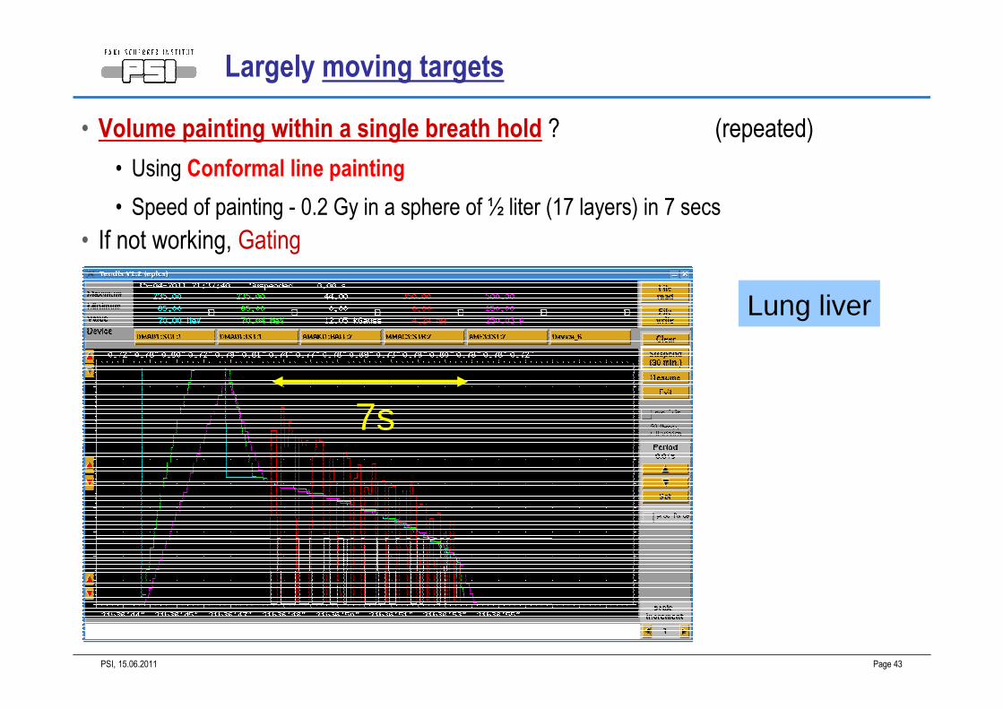
Largely moving targets
• Volume painting within a single breath hold ? (repeated)
• Using Conformal line painting
• Speed of painting - 0.2 Gy in a sphere of ½ liter (17 layers) in 7 secs
• If not working, Gating
7s
Lung liver
15.06.2011PSI, Page 44
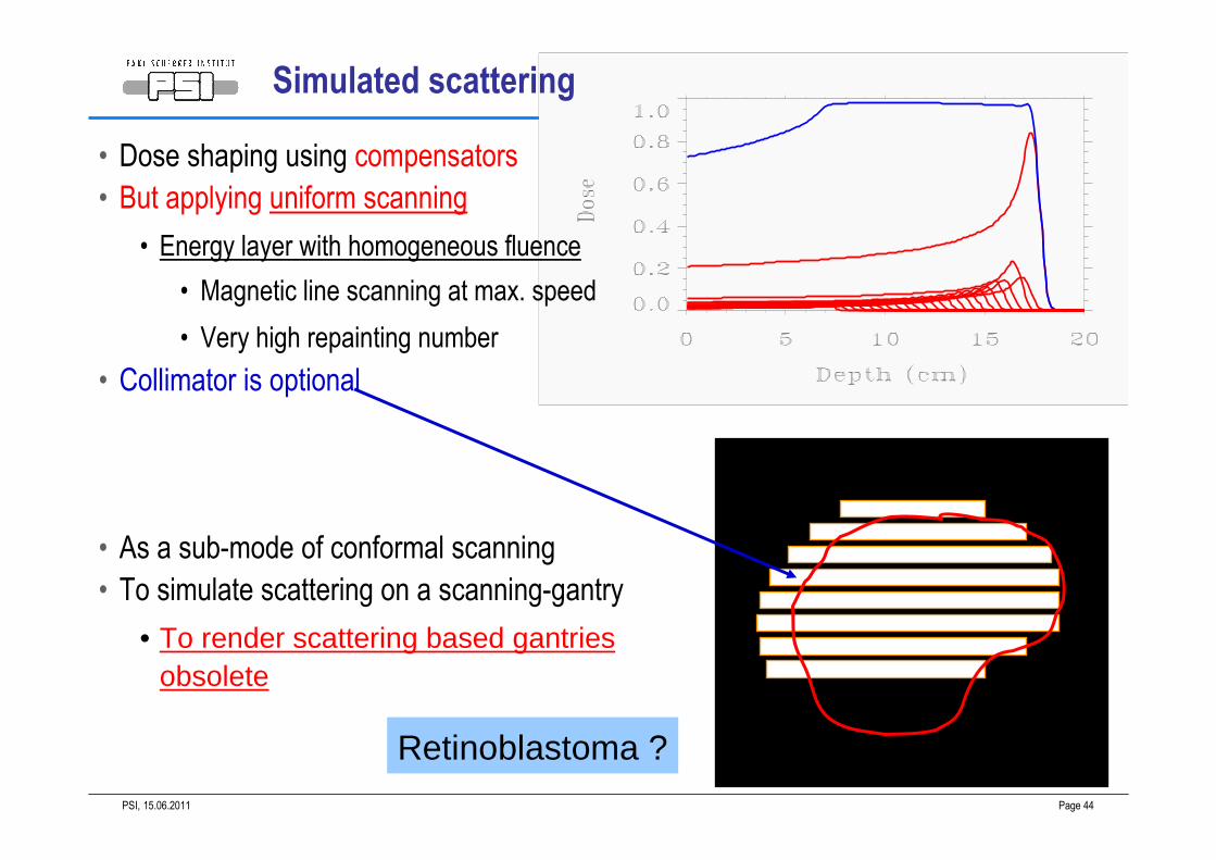
Retinoblastoma ?
Simulated scattering
• Dose shaping using compensators
• But applying uniform scanning
• Energy layer with homogeneous fluence
• Magnetic line scanning at max. speed
• Very high repainting number
• Collimator is optional
• As a sub-mode of conformal scanning
• To simulate scattering on a scanning-gantry
• To render scattering based gantries obsolete
15.06.2011PSI, Page 45
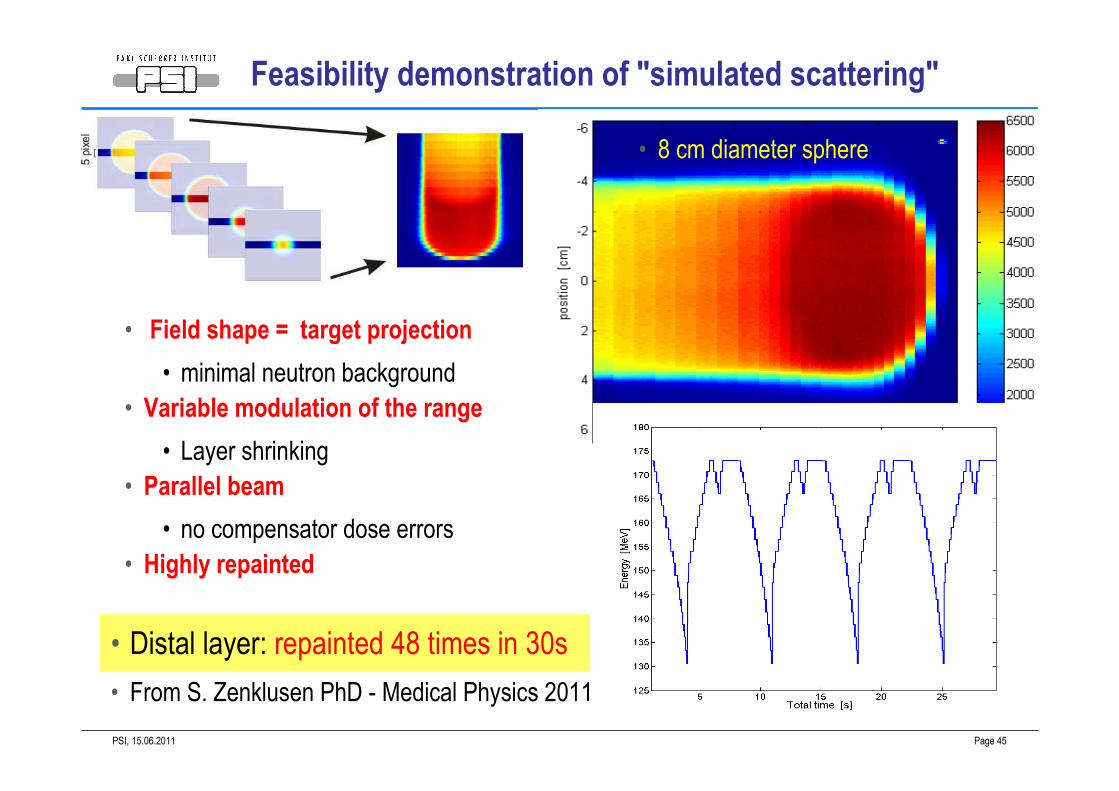
• Distal layer: repainted 48 times in 30s
• 8 cm diameter sphere
Feasibility demonstration of "simulated scattering"
• Field shape = target projection
• minimal neutron background
• Variable modulation of the range
• Layer shrinking
• Parallel beam
• no compensator dose errors
• Highly repainted
• From S. Zenklusen PhD - Medical Physics 2011
15.06.2011PSI, Page 46
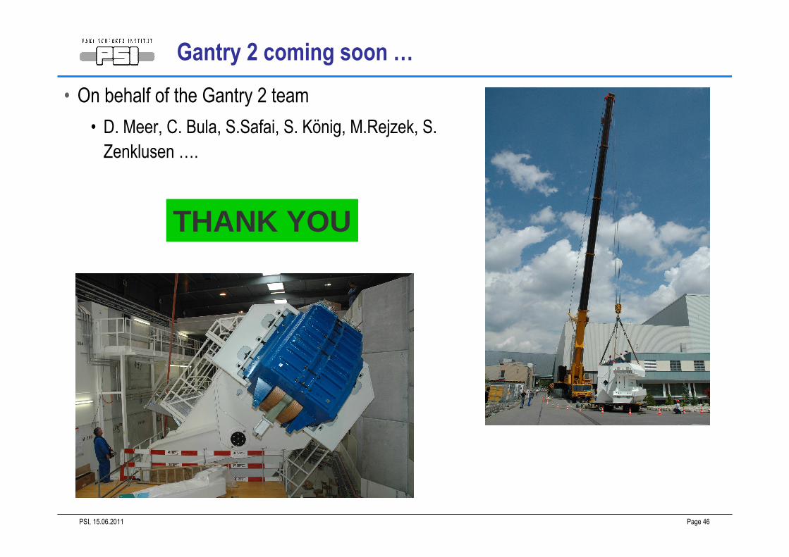
Gantry 2 coming soon …
• On behalf of the Gantry 2 team
• D. Meer, C. Bula, S.Safai, S. König, M.Rejzek, S.
Zenklusen ….
THANK YOU