Embed Size (px)
DESCRIPTION
ATPIAL Quick Ref Card
Citation preview
AN/PEQ-15 ATPIAL QUICK REFERENCE GUIDEThe Advanced Target Pointer Illuminator Aiming Light (ATPIAL) is a multifunctionlaser device that emits visible or infrared (I R) light for precise weapon aiming andtarget I area illumination. This guide provides a quick reference of the keyfeatures of the ATPIAL. Complete familiarization with the Operator and FieldMaintenance Manual prior to using the equipment will ensure safe operationand maximum effectiveness of the ATPIAL.
SAFETY SUMMARYThe ATPIAL emils bolh visible and invisible laser radiation. Nominal OcularHazard Dislances for safe operation (NOHD) are listed in the table below.
II WARNING ILaser modes designated as Safety Class 1 or 3R (lOW power) may be used forforce-an-force training only if Ihe opposing forces are beyond the NOHD valuesshown in the lable below.
~ WARNING IILaser modes designaled as Safely Class 3B (high power) shall NOT be usedfor force-cn-force training.
[I WARNING II
00 not stare into the laser beams.Do not look into the laser beams through binoculars or telescopes.
• Do not point the laser beams at mirror-like surfaces.• Do not shine the laser beams into other individual's eyes.
II WARNING IIThe ATPIAL's IR lasers are more detectable to an enemy using nighl visiondevices when used in smoke, fog, and rain. Avoid prolonged activalion of the IRlasers in these conditions.
laser Safety Dala
AL AL AH AHw/ IH DL DH DLwI DHwlFilter Fill ••.• Fllten
CIIIss 3R , 39 , 3B 39 39 , ,NOHD unaided 101m Om 234m Om 57.1m 32.6m "Om Om OmNOHO 5cmaided 654m Om 1.34km Om 336m 161m 1.38km Om OmNOHD gem aid&d 1.0000m om 2.11km Om 539m 255m 2.16km Om omNOHD 12cm aided 1.52km Om 3.09luTl Om 803m 37&n 3. 16km Om omNSHD Om Om Om Om Om Om Om Om Om00 unaided 0.7 1.7 1., 0.6 2.'00 aided 0.7 1.6 1., 0.6 2'
Rev. 3 ATP-QAG-M~AL
OPERATING INSTRUCTIONSMode Selection. Turn Ihe Mode Seleclor Switch to the desired position.
Modes of Operation
VI$IBLEAIMClass 3R
Position Mode Remarks
The ATPIAL will not operate. Prevents inadvenentemission of laser enerov.
VISAL
DUAL HIGHClass 38
Visible Aim Laser is selected. Visible without the use ofni hI vision devices.
o OFF
Programming Mode is selected 10 set the desiredInfrared IA IlILrninator Dulse rate.
PROGRAM
AL AIM LOWClass 1
IA Aim Laser is selected at high power. Visible with theuse of niaht vision devices.
DL DUAL LOWClass 1/3A
IR Aim Laser is selected at low power. Visible with theuse of nioht vision devices.IR Aim Laser and IR IIh.rninator are both selected at lowDOwer. Visible with the use of nioht vision devices.
AH AIM HIGHClass 38
IR Aim Laser and IR Illuminator are both selected athi h power. Visible with the use of nioht vision devices.
IHILLUMINATOR
HIGHClass 38
DH
IR Illuminator is selected at high power. Visible with theuse of night vision devices.
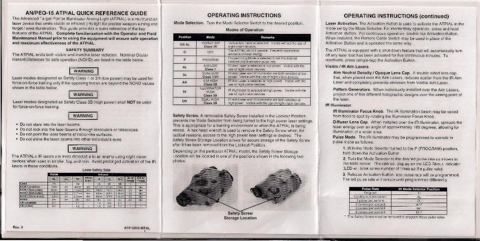
Safety Screw. A removable Safety Screw installed in the Lockout Positionprevents the Mode Selector from being turned to the high power laser settings.This is appropriate for a training environment or when the ATPIAL is beingstored. A hex head wrench is used to remove the Safety Screw when, for.tactical reasons, access to the high power laser settings is desired. TheSafety Screw Storage Location allows for secure storage of the Safety Screwatter it has been removed from the Lockout Position.
Depending on the particular ATPIAL model, the Safety Screw StorageLocation will be located in one of Ihe positions shown in the following Iwophotos.
Safety ScrewStorage Location
OPERATING INSTRUCTIONS (continued)Laser Activation. The Activation Button is used to activate the ATPIAL in themode set by the Mode Selector. For momenlary operation, press and holdActivation Button. For continuous operation, double-tap Activation Button.When installed, the Remote Cable Switch may be used in place of IheActivation Button and is operated the same way.
The ATPIAL is equipped with a shut-down feature that will automatically turnoff any laser that has been activated for five continuous minutes. Toreactivate, press (single-tap) the Activation Button.
Visible IIR Aim Lasers.
Aim Neutral Density I Opaque Lens Cap. A double-sided lens capthat, when placed over the Aim Lasers, reduces scatter from the IR AimLaser and completely prevents emission from Visible Aim Laser.
Pattern Generators. When individually installed over the Aim Lasers,project one of five different holographic designs over the aiming point ofthe laser.
IA Illuminator.
IR Illuminator Focus Knob. The IR illumination beam may be variedfrom flood to spot by rotating the Illuminator Focus Knob.
Diffuser Lens Cap. When installed over the IR Illuminator, spreads thelaser energy over an angle of approximately 180 degrees, allowing forillumination of a wider area.
Pulse Mode. The IR lIIuminalor may be programmed to operate inpulse mode as follows:
1. With the Mode Selector turned 10 the P (PROGRAM) position,hold down the Activation Button.
2. Turn the Mode Selector to the desired pulse rate as shown inthe table below. The rate will display on the LED Status Indicator(LED will blink same number of times as the pulse rate).
3. Release Activation Button, and pulse rate will be programmed.The set pulse rate will remain until programmed differently.
Pro ram PContinuous no ulse AL
1 ulse et second DL2 ulses er second AH"4 ulses er second IH"8 pulses per second DW
• The Safety Screw must be removed 10 program these pulse rates.
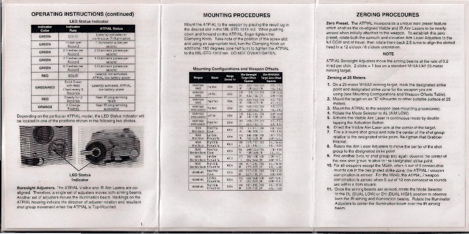
OPERATING INSTRUCTIONS (continued)lED Status Indicator
Indicator Indicator ATPIAL StatusColor Rate
GREEN SOLIDLaser(s) activated or
continuous IA Illumination
GREEN1 Flash per 1 illuminator pulse per
Second second
GREEN2 Flashes per 2 illuminator pulses per
Second second
GREEN4 Flashes per 4 illuminator pulses per
Second second
GREEN8 Flashes per B illuminator pulses per
Second second
RED SOLIDLaser(s) not activated,
ATPIAL low batterv powerSolid Green
GREEN/REDwith Red Laser(s) activated, ATPIAL
Flash every 5 low battery powerSeconds
REDSteady for 2 Near IR programming
Seconds failed
ORANGE3 Orange Near IA programmingFlashes successful
Depending on the particular ATPIAl model, the lED Status Indicator willbe located in one of the positions shown in the following two photos.
lED StatusIndicator
Boresight Adjusters. The ATPIAl Visible and IR Aim l.asers are co-aligned. Therefore, a single set of adjusters moves both aiming beams.Another set of adjusters moves the illumination beam. Markings on theATPIAl housing indicate the direction of adjuster rotation and resultantshot group movement when the ATPIAl is Top-Mounted.
MOUNTING PROCEDURES
Mount the ATPIAl to the weapon by placing the recoil lug inthe desired slot in the Mll-STD-1913 rail. While pushingdown and forward on the ATPIAl, finger tighten theClamping Knob. Take note of the position of the screw slotand using an appropriate tool, turn the Clamping Knob anadditional 180 degrees (one half tum) to tighten the ATPIAlto the Mll-STD-1913' rail. DO NOT OVERTIGHTEN.
Mounting Configurations and Weapon Offsets
Range10m Boresrght 2SmM16A2}A4
Weapon Nount Zeroed To TargetOHset Target Zero OHsetSquares Squares
/l4IMl€}.4)TapRajl I - VIS 2.ORfl.5~ VIS 2.5lfl.5U
MWS IR 1.5R125U IR 1.5UO.5UM4IMl6A4 LellRaiI :;00.,; VIS 3.OlJO.0 VIS 2.5=1/3.5U
MWS IR t..rJ.../l.00 IR 3.5R/4.5UM4IMl6A4 Rit$llRail
"""VIS 3.0R/4.50 VIS 3.OL/7.W
MWS IR 4.00/350 R 4.0L/6.OU114iM16A4
Tap Rail """VIS 2.0~/4.5U VIS 2.Sl/0.0
MWSwJ'J..\203 IR 1.OOJ55U R 1.SL/0.SU1I4IM1SA4
lell Rail 300m VS 3.Sl/0.SU VIS 2.5=1/2.SUMWSw/M203 IR 4.Sl I 0.50 IR 3.5R/3.5UM4IM1SA4 Right Rail 300m VIS S.sR/1.00 VIS 4.0L/S.W
MWSw/M203 IR 4.SR/I.50 IR S.OUS.OU1.1249 Feed Tray 400m VIS D.O/4.0U VIS 3.04../4.0U
Short Barrel Cover IR 1.000/S.oo IR 2.QU3.0UM249 Left Side 400m
VIS 6.OLt3.SD VIS l.SA/l1.OUShort Barrel Forward Rajl IR 7.01./4.50 " 2.5F1/12.OU
M249 RighI Side 400m VIS 2.SRn.So VIS J.SltI4.5UShort Barrel Forward Rail IR 3.SR/6.5D IR 4.Sll13.SU
M249 Feed Tray 400mVIS 2.0Rf2.0U VIS 1.5l/4.OU
Standard Barrel Cover IR 1.0RIJ.OU IR O.Sl/3.0UM249 ten see 400m VIS S.Ol/4.0D VIS 4.SR/II.OU
Standard Barrel For.vardRail IR S.OlIS.OD IR S.SAI12.0UM249 AightSlde
'00mVIS 4.7A/9.S0 VIS 3.01l1S.OU
SlandardBarrel Forward Rail IR S.7R/a.50 IR 4.0l/It..OU
M240BMG Feed Tray SOOn VIS 3.0A/0.5U VIS 2.0US.OUCover IR 2.0R/I.SU IR I.OUS.OU
M2400MG lehSide500m
VIS 4.0l/S.0D VIS S.OR/12.5UForward Aa~ IR 5.0./S.00 IR 6.OR113.5U
M2408 MGRighlSKie
SOOn VIS 5.SA/8.50 VIS 4.0UI6.OUForward Pa~ IR 6.SRf7.S0 IR S.OLI 17.QU
ZEROING PROCEDURES
Zero Preset. The ATPIAL incorporates a unique zero preset featurewhich enables the co-aligned Visible and IR Aim lasers to be nearlyzeroed when initially attached to the weapon. To establish this zeropreset, rotate both the azimuth and elevation Aim laser Adjusters to thefull CCW end of travel, then rotate them back 2.5 turns to align the slottedhead in a 12 o'clock / 6 o'clock orientation.
NOTE
ATPIAl Boresight Adjusters move the aiming beams at the rate of 0.2mrad per click. 2 clicks = 1 box on a standard M16A1/A2 25 meterzeroing target.
Zeroing at 25 Meters
1. On a 25-meter M 16A2 zeroing target, mark the designated strikepoint and designated strike zone for the weapon you areusing (see Mounting Configurations and Weapon Offsets Table).
2. Mount the target on an "E" silhouette or other suitable surface at 25meters.
3. Mount the ATPIAl to the weapon (see mounting procedures).4. Rotate the Mode Selector to AL (AIM lOW).5. Activate the Visible Aim Laser in continuous mode by double-
tapping the Activation Button.6. Direct the Visible Aim Laser aim at the center of the target.7. Fire a 3-round shot group and note the center of the shot group
relative to the designated strike paint. Re-tighten Rail GrabberBracket.
8. Rotate the Aim laser Adjusters to move the center of the shotgroup to the desiqnated strike point.
9. Fire another 3-round shot group and again observe the center ofthe new shot group relative to the designated strike point.
10. For all weapons except the M249, when 5 out of 6 consecutiverounds are in the desiqnatad strike zone, the ATPIAl I weaponcombination is zeroed. For the M249, the ATPIAL! weaponcombination is zeroed when 5 out of 12 non-consecutive roundsare within a 6cm square.
11. Once the aiming beams are zeroed, rotate the Mode Selectorto the Dl (DUAL lOW) or DH (DUAL HIGH) position to observeboth the IR aiming and illumination beams. Rotate the IlluminatorAdjusters to center the illumination beam over the IR aimingbeam.