Embed Size (px)
Citation preview
7/30/2019 Performance Analysis of the Constructed Updraft Biomass Gasifier for Three Different Biomass Fuels
http://slidepdf.com/reader/full/performance-analysis-of-the-constructed-updraft-biomass-gasifier-for-three 1/6
International Journal of Modern Engineering Research (IJMER)
www.ijmer.com Vol. 3, Issue. 4, Jul - Aug. 2013 pp-2056-2061 ISSN: 2249-6645
www.ijmer.com 2056 | Page
Prince Yadav1, Amit Dutta2, Dr. Bhupendra Gupta3, Dr. Mukesh Pandey4 1Student Master of Engineering, Heat Power, JEC, Jabalpur
2
Assistant Professor, GRKIST, Jabalpur, M.P.3 Assistant Professor, Jabalpur Engineering College, Jabalpur, India
4 Proffesor, School of Energy and Environment, UIT, RGPV Bhopal, India
Abstract: Gasification is the process in which a solid carbonaceous fuel is converted into combustible gas using partial
amount of air. The gases which evolve are known as “ producer gas”. This gas is more suitable than the direct combustion of
biomass. In this paper an updraft gasifier is constructed and is used to carry out the experiment. The waste material like
bagasse (sugarcane waste), coconut shells and wood particles are used for the generation of producer gas. The sense of this
paper is to study the effect of waste products in form of biomass. The performance of the gasifier is evaluated in terms of
zone temperature with different air velocity. By taking the different fuels and varying the air flow rate the temperature of the
zones are analyzed. The gas composition is not considered. The arrangement of tar is also seen in this apparatus. After
analysis it is found that the coconut shell having maximum temperature for all three zones as compare to other two sococonut shell is the best suitable material for this gasifier.
Keywords: Biomass gasification, construction, updraft gasifier, temperature analysis.
I. IntroductionBiomass is an organic material, including plant matter from trees, grasses, and agricultural crops. The chemical
composition of biomass varies among species, but basically consists of high, but variable moisture content, a fibrousstructure consisting of lignin, carbohydrates or sugars, and ash. Biomass is very heterogeneous in its natural state and
possesses a heating value lower than that of coal.
Gasification is a more than century old technology, which flourished before and during the Second World War. The
technology disappeared soon after the Second World War, when liquid fuel (petroleum based) became easily available.
During the 20th century, the gasification technology roused intermittent and fluctuating interest among the researchers.
However, today with rising prices of fossil fuel and increasing environmental concern, this technology has regained interestand has been developed as a more modern and sophisticated technology. A process of conversion of solid carbon fuels into
combustible gas by partial combustion known as gasification. The resulting gas known as producer gas (with thecomposition of CO 15-20%, H₂ 10-15%, CH₄upto4%, N₂ 45-55%, CO₂ 8-12%), is more versatile in its use then the original
solid biomass. The equipment used for this gasification process is known as gasifier. Gasification is primarily a thermo-
chemical conversion of organic materials at elevated temperature with partial oxidation. In gasification, the energy in biomass or any other organic matter is converted to combustible gases (mixture of CO, CH4 and H2), with char, water, and
condensable as minor products. Initially, in the first step called pyrolysis, the organic matter is decomposed by heat into
gaseous and liquid volatile materials and char (which is mainly a nonvolatile material, containing high carbon content). In
the second step, the hot char reacts with the gases (mainly CO2 and H2O), leading to product gases namely, CO, H2 and CH4.
The producer gas leaves the reactor with pollutants and therefore, requires cleaning to satisfy requirements for engines.
Mixed with air, the cleaned producer gas can be used in gas turbines (in large scale plants), gas engines, gasoline or diesel
engine.
1.1 Processes of Gasification: Four distinct processes in the gasifier -
1. Drying :- In this stage, the moisture content of biomass is typically reduced to be 5-35%.In drying zone the temperature
is about 100-200°C.2. Pyrolysis:-It is the first step in the combustion or gasification of biomass. When biomass heated in the absence of air to
about 350-600°C,it form charcoal, gases and tar vapors.
Biomass + heat → solid, liquid, gases products (H2 , H2O, CO , CO2)
3. Combustion: - In this process the reaction between solid carbonized biomass and oxygen in the air, resulting in
formation of CO2. Hydrogen present in the biomass is also oxidized to generate water. Large amount of heat is releasedwith the oxidation of carbon and hydrogen.
C+ O2 → CO2
4. Reduction: - In absence of oxygen, several reduction reactions occur in the temperature range of 600-1000ºC. These
reactions are mostly endothermic. The major in this category are as follows:
C+H2O → CO +H2
C+CO2↔
2COCO2+H2 ↔ CO+ H2O
C + 2H2 ↔ CH4
Performance Analysis of the Constructed Updraft Biomass
Gasifier for Three Different Biomass Fuels
7/30/2019 Performance Analysis of the Constructed Updraft Biomass Gasifier for Three Different Biomass Fuels
http://slidepdf.com/reader/full/performance-analysis-of-the-constructed-updraft-biomass-gasifier-for-three 2/6
International Journal of Modern Engineering Research (IJMER)
www.ijmer.com Vol. 3, Issue. 4, Jul - Aug. 2013 pp-2056-2061 ISSN: 2249-6645
www.ijmer.com 2057 | Page
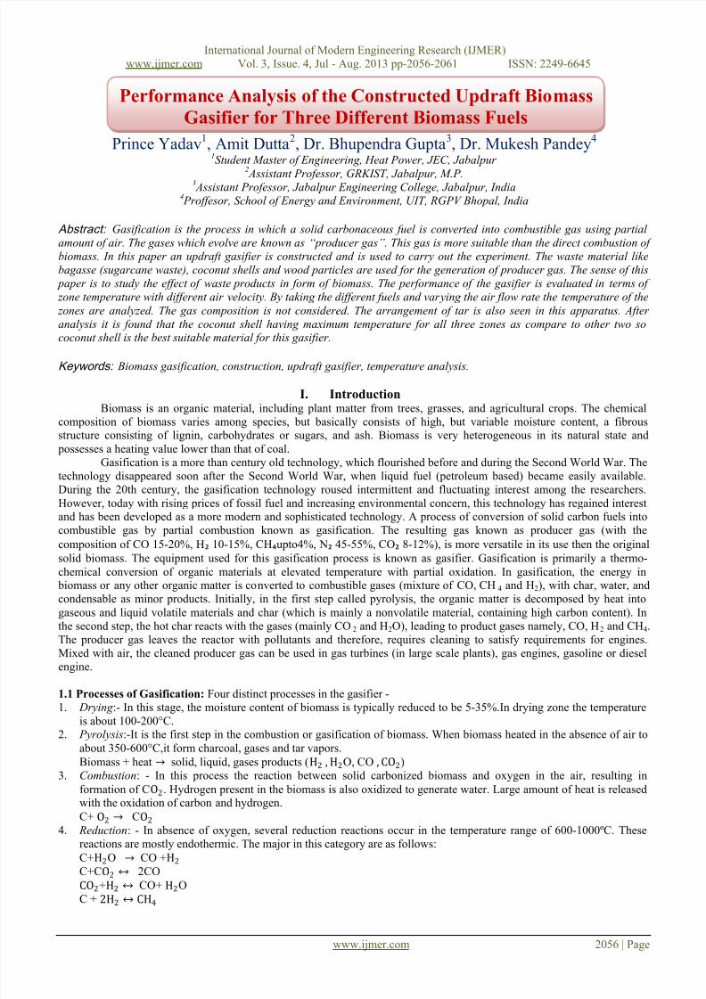
1.2 Classification of biomass gasifier: They are classified according to the way air or oxygen is introduced in it. There are
three types of gasifier-
1.3.1) Downdraft: Biomass is introduced from the top and moves downward. Oxidizer (air) is introduced at the top and
flows downward. Producer gas is extracted at the bottom at grate level.
1.3.2) Updraft: Biomass is introduced from the top and moves downward. Oxidizer is introduced at the bottom and flows
upward. Some drying occurs. Producer gas is extracted at the top.
1.3.3) Cross draft: Biomass is introduced from the top and moves downward. Oxidizer is introduced at the bottom and
flows across the bed. Producer gas is extracted opposite the air nozzle at the grate.
Fig. 1.1- Types of biomass gasifier
Our current work focused on the construction of updraft gasifier and performance analysis of the updraft gasifier.
There are various biomass materials are available in the countries. Where in the following three bio mass materials which are
commonly available and reliable were taken for performance analysis of the updraft gasifier – wood chips, sugarcane waste,and coconut shells.
II. Construction of Updraft Biomass GasifierThe original aim with this gasifier project, were to build a compact and simple gasifier, that used inexpensive
feedstock (like wood chips or mulch that is available very inexpensively, or even free), and produced high-quality gas. Theresearch showed that the updraft gasifier design generally produced the best quality gas. Some gasifier designs are quite
complex and difficult to fabricate, others much simpler. So naturally,we gravitated toward the simpler design. Thework
originally aimed to building a simple open core design.
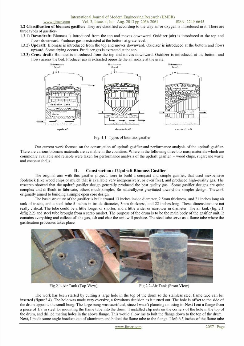
The basic structure of the gasifier is built around 13 inches inside diameter, 2.5mm thickness, and 21 inches long air
tank of trucks, and a steel tube 5 inches in inside diameter, 3mm thickness, and 22 inches long. These dimensions are not
really critical. The tube could be a little longer or shorter, and a little wider or narrower in diameter. The air tank (fig. 2.1
&fig 2.2) and steel tube brought from a scrap market. The purpose of the drum is to be the main body of the gasifier unit. It
contains everything and collects all the gas, ash and char the unit will produce. The steel tube serve as a flame tube where the
gasification processes takes place.
Fig.2.1-Air Tank (Top View) Fig.2.2-Air Tank (Front View)
The work has been started by cutting a large hole in the top of the drum so the stainless steel flame tube can be
inserted (figure2.4). The hole was made very oversize, a fortuitous decision as it turned out. The hole is offset to the side of
the drum opposite the small bung. The large bung was sacrificed, since I wasn't planning on using it. Next I cut a flange froma piece of 1/8 in steel for mounting the flame tube into the drum. I installed clip nuts on the corners of the hole in the top of
the drum, and drilled mating holes in the above flange. This would allow me to bolt the flange down to the top of the drum.
Next, I made some angle brackets out of aluminum and bolted the flame tube to the flange. I left 6.5 inches of the flame tube

7/30/2019 Performance Analysis of the Constructed Updraft Biomass Gasifier for Three Different Biomass Fuels
http://slidepdf.com/reader/full/performance-analysis-of-the-constructed-updraft-biomass-gasifier-for-three 3/6
International Journal of Modern Engineering Research (IJMER)
www.ijmer.com Vol. 3, Issue. 4, Jul - Aug. 2013 pp-2056-2061 ISSN: 2249-6645
www.ijmer.com 2058 | Page
sticking up above the flange. The rest protrudes down into the drum. Here the unit is being test fit on top of the drum. The
holes in the ends of the angle brackets are over the clip nuts in the top of the drum.The high temperature silicone gasket
material (figure2.5) is used to seal every crack, crevasse, joint and bolt hole in the gasifier.
Fig.2.3-Cutting of the air tank Fig.2.4-Cutting flange for tank
Fig.2.5- Silicon gasket Fig.2.6- Six numbers of j type copper tubes
Here I have installed the six j-tubes (figure 2.6). They are made of 1cm inside diameter, 0.5mm thickness, and 1foot
length copper tubing. They are called j-tubes because they are shaped like the letter J. I used a large hose clamp cinched
down tight to hold the tubes in place. The opening in the top of the drum needed to have a few notches cut in it to
accommodate a couple of the j-tubes that stuck out too far.
The constrictor plate (figure 2.7) installed in the bottom of the flame tube. To make the plate I cut a circle out of a11
inch sheet steel that would fit in the bottom of the flame tube. Then I cut a 1.6 inch diameter hole in the center of the circle.
To mount the constrictor in the flame tube, I welded three 1/4-20 nuts to the plate, and drilled passage holes in the flame tube
for three 1/4-20 bolts. The manifold I made to cover the inlets of all six j-tubes. It was cut from a 6 in to 4 in steel AC duct
reduction fitting. It slips down over the flame tube and covered all six j-tubes. A single air inlet fitting will be installed on the
side of the manifold.
Fig.2.7-Constrictor plate Fig.2.8- Updraft gasifier
After this, the gasifier is ready to use. But before starting the gasifier, it has been equipped with all the measuring
instruments to take the readings.
III. Experimental Setup and ProcedureIn this setup, the updraft biomass gasifier installed with the blower of different speeds, Anemometer, k-type thermo
couples and digital temperature reader. First of all, the pulverized coal is heated with direct burning and this coal is used for the initial combustion of biomass fuel. This burn coal placed to the grate. Firstly, I used wood chips as a biomass fuel and
filled the flame tube and closed the upper portion of the flame tube with the special type cap. The cap has two outlet valves
for the producer gas. One is going to the burner and another to the nozzle.

7/30/2019 Performance Analysis of the Constructed Updraft Biomass Gasifier for Three Different Biomass Fuels
http://slidepdf.com/reader/full/performance-analysis-of-the-constructed-updraft-biomass-gasifier-for-three 4/6
International Journal of Modern Engineering Research (IJMER)
www.ijmer.com Vol. 3, Issue. 4, Jul - Aug. 2013 pp-2056-2061 ISSN: 2249-6645
www.ijmer.com 2059 | Page
Fig.3.1- Experimental setup of updraft biomass gasifier
Fig. 3.2- Experimental setup and burning flame in the burner
Further, blower is started with minimum speed of air inlet and the gasifier has been started. When the velocity of
inlet air increases, the combustion presses of the gasifier become faster.This time the temperature of the three different zones
of the gasifier increase greatly. The readings of different air velocity have been taken from the Anemometer and
temperatures of three different zones taken from the Digital Temperature reader. This process continues with the other two
fuels, sugarcane wastes and coconut shells.
IV. Results and DiscussionThe gasification experiments were performed in the heat engine laboratory of the JEC, Jabalpur for three different
biomass materials for the performance analysis of the constructed updraft biomass gasifier. The different velocity of air wasmeasured with an Anemometer. The pyrolysis, reduction and oxidation zone temperature were also monitored with the aid of
K type thermocouples.The temperatures of the three different zones at different air velocities of the producer gas for these three materials
were found out (Table 4.1, Table 4.2, and Table 4.3).
The comparison of Temperatures for these biomass materialswith respect to the air velocity are shown in the graph
given below:
Table1: Different zone temperatures at different air velocities for wood chips.
Air velocitie
s
(m/sec.)
Temperature of Pyrolysis zone
(˚C)
Temperature of Reduction zone
(˚C)
Temperature of Combustion
zone
(˚C)
0.8 380 405 4201.2 470 520 535
1.8 495 542 578
2.2 585 610 635

7/30/2019 Performance Analysis of the Constructed Updraft Biomass Gasifier for Three Different Biomass Fuels
http://slidepdf.com/reader/full/performance-analysis-of-the-constructed-updraft-biomass-gasifier-for-three 5/6
International Journal of Modern Engineering Research (IJMER)
www.ijmer.com Vol. 3, Issue. 4, Jul - Aug. 2013 pp-2056-2061 ISSN: 2249-6645
www.ijmer.com 2060 | Page
Table2: Different zone temperatures at different air velocities for Sugarcane waste.
Air
velocities
(m/sec.)
Temperature
of Pyrolysis
zone (˚C)
Temperature
of Reduction
zone (˚C)
Temperature of
Combustion
zone (˚C)
0.8 315 356 380
1.2 460 485 510
1.8 625 658 6832.2 542 558 576
Table3: Different zone temperatures at different air velocities for Coconut shells.
Air
velocities
(m/sec.)
Temperature
of Pyrolysis
zone (˚C)
Temperature
of Reduction
zone (˚C)
Temperature of
Combustion
zone (˚C)
0.8 535 558 610
1.2 595 638 796
1.8 705 780 835
2.2 785 810 880
Fig 4.1: Comparison of Pyrolysis zone temperature (oC) for different biomass materials with constant variations of air
velocity (m/s).
Fig 4.2: Comparison of Reduction zone temperature (oC) for different biomass materials with constant variations of air
velocity (m/s).
0
100
200
300
400
500
600
700
800
900
0 1 2 3
Wood chips
T e m p e r a t u r e ( O C )
Air Velocity→
0
100
200
300
400
500
600
700
800
900
0 1 2 3
Wood chips
Sugarcane Waste
Coconut shell
T e m p e r a t u r e ( O C )

7/30/2019 Performance Analysis of the Constructed Updraft Biomass Gasifier for Three Different Biomass Fuels
http://slidepdf.com/reader/full/performance-analysis-of-the-constructed-updraft-biomass-gasifier-for-three 6/6
International Journal of Modern Engineering Research (IJMER)
www.ijmer.com Vol. 3, Issue. 4, Jul - Aug. 2013 pp-2056-2061 ISSN: 2249-6645
www.ijmer.com 2061 | Page
Fig 4.3: Comparison of Combustion zone temperature (oC) for different biomass materials with constant variations of air
velocity (m/s).
By analyzing the graph, it is found that, when the air velocity increases from 0.8m/sec. to 2.2 m/sec, the pyrolysis,
Reduction, and combustion zone temperatures also increases gradually. The temperature of the pyrolysis zone varies from315˚C to 785˚C at the constant variation of the air velocity. The Temperature of combustion zone varies from 380˚C to
880˚C at the similar variation of the air velocity. The Temperature of Reduction zone varies from 356˚C to 810˚C at thesimilar variation of the air velocity.
The combustion zone temperature depends upon the heat released due to the biomass combustion and air flow rate.
The increasing in combustion zone temperature means that there is greater amount of oxygen takes provides by increasing
air velocity but also brings inert N₂, which acts as a heat barrier and reduces the temperature of the combustion and pyrolysis
zone. The maximum value of temperature in pyrolysis and combustion zone represents the optimum amount of biomassconsumption rate. From the analysis of previous papers, it is assumed that, at the optimum amount of biomass combustion,
the amount of carbon monoxide and hydrogen produced are maximum and the fraction of carbon dioxide is minimum.
V. ConclusionThe experimental analysis for different biomass materials clearly show that the coconut shell having the greater
temperature for all the zones as compare to the other two, when the air velocity increases. Maximum temperature of the different
zones for coconut shell represents the optimum amount of combustion. The energy released will increase the rate of drying and
pyrolysis. Optimum amount of biomass consumption rate is not only due to a higher combustion rate, but also due to the
enhanced pyrolysis and drying rate. So, the coconut shell is best suitable material for the above constructed updraft biomassgasifier as compare to the other two. The coconut shell is one of the waste biomass and easily available material.
References [1] Pratik N. Sheth et al. (2009) -Experimental studies on producer gas generation from wood waste in a downdraft biomass gasifier.
Bioresource Technology 100 (2009) 3127 – 3133.
[2] J.K. Ratnadhariya et al. (2010) - Experimental studies on molar distribution of CO/CO2 and CO/H2 along the length of downdraftwood gasifier. Energy Conversion and Management 51 (2010) 452 – 458.
[3] K. Sivakumar et al. (2010) - Performance analysis of downdraft gasifier for agriwaste biomass materials. Indian Journal of Scienceand Technology (Jan 2010) ISSN: 0974- 6846.
[4] Sarah Rowland et al. (2009) - Updraft Gasification of Salmon Processing Waste.Journal of food science E427.[5] J.J. hernández et al. (2012) - Combustion characterization of producer gas from biomass gasification. Global NEST Journal, Vol
14, No 2, pp 125-132, 2012.[6] Jeng-ChyanMutiLin (2006) -Development of an updraft fixed bed gasifier with an embedded combustor fed by solid biomass.
Journal of the Chinese Institute of Engineers, Vol. 29, No. 3, pp. 557-562 (2006).[7] V. N. Raibhole- Syngas Production By Updraft Biomass Gasifer And Its Parametric Analysis. IOSR Journal of Mechanical and
Civil Engineering (IOSR-JMCE) ISSN (e): 2278-1684, ISSN (p): 2320 – 334X, PP: 56-62.[8] Adnan Midilli, Murat Dogru, Colin R, Howarth Mike, Ling J and Teoman Ayhan (2001)-Combustible gasproduction from sewage
sludge with a down draft gasifier. Energy Conservation & Management; 42, 157-172.[9] Avdhesh K and Sharma R (2009) - Experimental studyon 75 KW the downdraft (biomass) gasifier system.[10] Renewable Energy. 34, 1726-1733.[11] Dogru M, Howarth CR, Akay G, Keskinler B and MalikAA (2002) - Gasification of hazelnut shells in a downdraft gasifier.
Energy. 27, 415-427.
[12] Khater EMH, El-Ibiary NN, Khattab IA and Hamad MA(1992) Gasification of rice hulls. Biomass &Bioenergy. 3, 329-333.
[13] Pattarporn Chairprasert and Tharapong Vitidsant (2009)-Promotion of coconut shell gasification by Steam reforming on nickle-dolomite. Am. J. Appl. Sci.6 (2), 332-336.[14] Paulo R. Wander and Carlos R (2004) - Assessment of a small saw dust gasification unit. Bio mass & Bio Energy. 27, 467-476.
0
100
200
300
400500
600
700
800
900
1000
0 0.5 1 1.5 2 2.5
Wood chips
Sugarcne waste
Coconut shell
T e m p e r t u r e ( O
C )