Embed Size (px)
Citation preview

Performance enhancement of VSAT MC-CDMA system using
channel coding techniques and Predistortion over Rayleigh channel
1Mohammed EL JOURMI,
2Hassan EL GHAZI,
1Abdellatif BENNIS,
3Hassan OUAHMANE
1Physics Department, Hassan II University, FSBM, Casablanca, Morocco
2Telecommunications Department, INPT, Rabat, Morocco
3Networks and Telecommunications Department, ENSA, El jadida, Morocco
Abstract: - In this paper, the performance of VSAT network, in uplink (earth station to a geostationary satellite)
and Ku-band have been examined over Rayleigh channel. The most popular type of multiple access schemes:
Code Division Multiple Access (CDMA) combined with the multi-carrier transmission system OFDM is used
in this study, in order to obtain a densification of data traffic on the network and achieve a high data rate. To
improve the performance of the envisaged system, and get a very low bit error rate, we proposed the use of
strategies allowing the correction of errors induced by the imperfections of the communication channel.
Channel coding techniques used in this study are (LDPC codes, Turbo codes and convolutional codes). In the
simulation results, we have demonstrated the effectiveness of each coding strategy in our communication
system. The integration of LDPC coding in our transmission chain has provided a significant gain compared to
other encoding schemes, and the bit error rate (BER) has reached a satisfying level at a low energy per bit to
noise power spectral density ratio ( / ). To compensate the effect of the non-linearity of the High Power
Amplifier HPA, a predistortion technique is adopted to further improve performance of the envisaged system.
Key-Words: - VSAT Network, MC-CDMA scheme, Channel coding, predistortion, Ku band, Uplink.
1 Introduction Today's satellites can be used in many
communication services requiring point to point or
point to multipoint. The use of satellites has solved
some problems in communication domain and this
basically amounts to the large area of coverage
provided by them. Thus, communication between
remote ground stations geographically is become
possible with the first commercial communications
satellite "Early Bird". The field of satellite
communications is still on a path of improvement,
but the major problem hindering its progress is the
presence of random errors on the satellite link and
that can significantly degrades the system
performance. For this reason we used channel
coding mechanisms to reduce the error rate and
improve the system performance.
The objective of this paper is to design a satellite
ground segment component for use in
telecommunications and analyze its performance.
Therefore, the ground segment is designed to fit in
the description of a Very Small Aperture Terminal
(VSAT), which requires antenna dimensions less
than 1.8 m in diameter. The designed system has a
wide bandwidth and use MC-CDMA scheme. In this
study, the BPSK is preferred for their low latency in
the modulation or demodulation process. In the
event of the destruction of the orthogonality
between user codes, the resulting multiple access
interference (MAI) severely limits the system
performance. In order to reduce the bit error rate
caused by intersymbol interference (ISI) or multiple
access interference (MAI) channel coding (LDPC
codes, Turbo codes and Convolutional codes) is
applied which can make error detection and
correction at the receiver. An adaptive equalization
technique must be used to compensate distortions
caused by propagation environment. Therefore, the
use of MMSE technique is able to improve
performance of the envisaged system in multipath-
interference environments. To be able to send
signals through great distance, the signals need to be
amplified before transmission. The High Power
Amplifier (HPA) of Rapp’s model which is based
on a Solide State Power Amplifier (SSPA) is used
and a low noise amplifier (LNA) is used to amplify
very weak signals captured by an antenna. To
compensate the effect of the non-linearity in the
communication system, a predistortion process
adapted to the SSPA amplifier is proposed. In this
study, the CDMA encoder uses PN sequences and
Walsh Codes to generate a spread signal. Each
VSAT uses a different PN sequence and each user
in a VSAT uses different Walsh Codes.
This paper is organized as follows. In Section 2 the
VSAT Network are briefly described with its
configurations. The principle of MC-CDMA scheme
is presented with modeling of proposed system in
Section 3. Section 4 presents the convolutional
codes principle. Sections 5 and 6, respectively,
WSEAS TRANSACTIONS on COMMUNICATIONSMohammed El Jourmi, Hassan El Ghazi, Abdellatif Bennis, Hassan Ouahmane
E-ISSN: 2224-2864 318 Volume 13, 2014

describe the principle of Turbo coding and LDPC
codes. In section 7 the simulation model and system
specifications are presented. Simulation results are
presented in Section 8, and conclusions are drawn in
Section 9.
2 VSAT Network The satellite communications networks using
Very Small Aperture Terminals (VSAT) appeared in
the 1980s. The appearance of these terminals
amounts in particular to the companies which wish
to rent analog or digital telephone lines with low
cost. VSATs networks allow bidirectional satellite
communication (i.e. earth stations play the role of a
transmitter and receiver), which eliminates
terrestrial link, unless the user wishes to
communication relief and to provide another type of
application such as video on demand [3].
There are two major network configurations viz:
the hub-based star VSAT network, which provides a
"star" type of topology, and the "mesh" network,
which allows connections between any pair of
VSATs.
2.1 Meshed configuration As all the VSATs are visible from the satellite,
carriers can be relayed by the satellite from any
VSAT to any other VSAT in the network as shown
in figure 1. This type of configuration is called
point-to-point topology. In this mesh type, earth
stations communicate directly via satellite and will
have only one hop communication.
Fig. 1 Meshed topology of VSAT Network
2.2 Star configuration This configuration is based on a station
larger than a VSAT in the network, called the hub.
The hub station has a larger antenna size than that of
a VSAT, about 4m to 11m resulting in a higher gain
than that of a typical VSAT antenna, and is
equipped with a more powerful transmitter [5]. As a
result of its improved capability, the hub station is
able to receive adequately all carriers transmitted by
the VSATs, and to convey the desired information
to all VSATs by means of its own transmitted
carriers. The architecture of the network becomes
star as shown in figure 2. The links from the hub to
the VSAT are named “outbound links” and the ones
from the VSAT to the hub are named “inbound
links”. Both inbound and outbound links consist of
two links, uplink and downlink, to and from the
satellite.
Fig. 2 Star topology of VSAT Network
In conclusion, star configuration is imposed by
power requirements resulting from the reduced size
and hence the low cost of the VSAT earth station in
conjunction with power limitation of the satellite.
Meshed configuration is considered whenever such
limitations do not hold, or are unacceptable. Meshed
networks have the advantage of a reduced
propagation delay (single hop delay is 0.25 sec
instead of 0.5 sec for double hop) which is
especially of interest for telephone service [2].
3 Multi-carrier CDMA Multi-carrier CDMA system is based on a
combination of the CDMA scheme and orthogonal
frequency division multiplexing (OFDM) signaling.
MC-CDMA transmitter spreads the original
signal using a given spreading code in the frequency
domain. In other words, a fraction of the symbol
corresponding to a chip of the spreading code is
transmitted through a different subcarrier.
Fig. 3 MC-CDMA Transmitter
WSEAS TRANSACTIONS on COMMUNICATIONSMohammed El Jourmi, Hassan El Ghazi, Abdellatif Bennis, Hassan Ouahmane
E-ISSN: 2224-2864 319 Volume 13, 2014

The figure 3 shows the MC-CDMA transmitter
for the user. The input information sequence is
first converted into P parallel data sequences, and
then each Serial/Parallel converter output is
multiplied with the spreading code with length .
All the data in total (corresponding to
the total number of subcarriers) are modulated in
baseband by the inverse Fast Fourier transform
(IFFT) and converted back into serial data. The
guard interval is inserted between symbols to
avoid intersymbol interference, and finally the
signal is transmitted.
Figure 4 shows the MC-CDMA receiver. It
requires coherent detection for successful
despreading operation and this causes the structure
of MC-CDMA receiver to be very complicated. In
figure, the k-subcarrier components (k=1,2,…Lc)
corresponding to the received data is first
coherently detected with FFT and then multiplied
with the gain to combine the energy of the
received signal scattered in the frequency domain
[6]-[7].
Fig. 4 MC-CDMA Receiver
3.1 Transmitter model of envisaged system Transmitted signal corresponding to the
data bit of the user is defined by:
b
S 1 N 1α,m
α,m α,m
0 l n 0
c α T b
b
2PS(t) W n b l
N
n cos 2π f t C U (t lT )
T
v
v
(1)
Where is the power of data bit,
is the rectangular pulse defined in the . Every user has a spreading code with
and is the length of the
sequence chip. The same signature sequence chip is
used to modulate each of the carriers of the
user. The maximum number of users in the system
is . Every VSAT has a signature with
and S is the length of the
spreading code. denote the number of VSATs
with and is the maximum number
of VSATs.
3.2 Receiver model of system over Rayleigh
channel The receiver signal of active users in the
VSAT-MC-CDMA system can be written as:
b
K S 1 M 1 N 1α,m
α,m,n α,m α,m
α 1 0m 0l n 0
c α,m,n α T b
b
2PR t φ W n b l
N
ncos 2π f t ψ C U t lT n t ξ(t)
T
v
v
(2)
Where and are respectively fading
amplitude and phase shift. is the additive white
Gaussian noise (AWGN) with double sided power
spectral density of and is the inter-VSAT
interference.
3.3 The Decision Statistic The information bits received from a user
specified and VSAT will be used
for this analysis. (α = β) and (m = j) are the indices
of despreaded information bits we want to retrieve.
All other values of α (α ≠ β) and m (m ≠ j) will be
considered co-channel interference and inter-VSATs
interference.
Assuming that users are synchronous in time,
after demodulation and combination of sub-carrier
signals, the decision variable is obtained as:
1 1
, , β, j,n β, j
0
c βα,m,n
b
1( ) G W [n]
ncos 2π f t ψ C dt
T
b
b
l T N
j l
nb lT
R tT
v
(3)
Where β is the equalizing coefficient of the
user from the earth station .
The decision variable consists of four
components, the first term corresponds to the
desired signal, the second term corresponds to the
multiple access interference from other users, the
third term corresponds to the noise and the last term
represents the interference between VSATs.
, ,j l (4)
: Signal désiré
: Interférence Co-canal
: Bruit blanc gaussien additif
: Interférence entre VSATs
WSEAS TRANSACTIONS on COMMUNICATIONSMohammed El Jourmi, Hassan El Ghazi, Abdellatif Bennis, Hassan Ouahmane
E-ISSN: 2224-2864 320 Volume 13, 2014

Note that the absence of interference between
symbols and the interference between carriers is
ensured by the use of a guard interval longer than
the delay spread of the channel impulse response.
Components of the decision variable can be
written in the following form:
Desired signal
N 1
β, j
β, j,n β, j β, j,n
l n 0
2P1 ( 1)φ b l G
2 NS
(5)
Co-channel interference
1 N 1
β,m
β,m,n β,m β, j,n0l n 0
β,m β, j β, j,n β,m,n
2P1φ b l G
2 N
W [n]W [n]cos(ψ ψ )
M
m
m j
(6)
Noise
b
b
l 1 TS 1 N 1
β, j,n β, j
0 n 0 b lT
β c β, j,n
b
1n(t)G W [n]
T
nC cos 2π f t ψ dt
T
v
v
(7)
Inter-VSATs interference
K S 1 M 1 N 1α,m
α,m,n α,m α,m1 0 m 0l n 0
β, j,n α β, j β β, j,n α,m,n
2P1 φ W n b l
2 N
G C W [n]C cos ψ ψ
v
v v
(8)
Generally speaking the user from the
earth station, the SNIR can be expressed as:
2
, β, j
, β, j
φ
φ
j
j
E
SNIR
(9)
Where is the
vector of fading amplitudes of the user from the
earth station . is variance.
Assume independent users and independent
subcarriers,
2
12, 2
, β, j β, j,n β, j,n
0
21φ ( 1) φ G
4
Nj
j
n
PE S
N
(10)
, j (11)
2 2 2
, j E E E
(12)
The variance of the noise components is:
1
20β, j , ,
0
φ4
N
j n
n
NG
T
(13)
The variance of the MAI can be expressed as
1 1
, 2
β, j , , , ,0 0
21 φ
8
M Nm
m n j nm n
m j
PE G
N
(14)
The variance of the inter-VSAT interference is:
1 1
, 2
β, j1 0 0
2
, , , ,
21φ ( 1)
8
K M Nm
m n
m n j n
PS
N
E G
(15)
The following expression is the total variance of
noise plus interferences of proposed system:
1
20, β, j , ,
0
1 1, 2
, , , ,0 0
1 1, 2 2
, , , ,1 0 0
φ4
21 8
21 ( 1)8
N
j j n
n
M Nm
m n j nm n
m j
K M Nm
m n j n
m n
NG
T
PE G
N
PS E G
N
(16)
4 Convolutional codes
A convolutional encoder generates code symbols
for transmission utilizing a sequential finite-state
machine driven by the information sequence.
Decoding these codes then amounts to sequentially
observing a corrupted version of the output of this
system and attempting to infer the input sequence.
From a formal perspective, there is no need to
divide the message into segments of some specific
length.
Figure 5 illustrates one of the simplest nontrivial
convolutional encoders. It is implemented by a shift
register of memory (number of delay elements) m =
2 and three summers ⊕ over Galois field GF(2).
The rate of the code is r = 1/2. The information
WSEAS TRANSACTIONS on COMMUNICATIONSMohammed El Jourmi, Hassan El Ghazi, Abdellatif Bennis, Hassan Ouahmane
E-ISSN: 2224-2864 321 Volume 13, 2014
sequence . . . β0, β1, . . . , βn . . . , βn ∈ {0, 1}, is the
input sequence of the encoder. The encoder is a
finite-state machine that can be described in terms
of its state transition diagram. This is shown in
Figure 6, where the nodes refer to the contents of
the register just before the next input bit arrives. The
encoder inputs . . . β0, β1, . . . , βn, . . . , and outputs .
. . α0, α1, . . . , αn, . . . , βn, αn ∈ {0, 1} (2 output
symbols per input bit for the rate r = 1/2 encoder)
are shown as labels on the transition branches[9]
Fig. 5 A rate r = 1/2 memory m = 2 convolutional encoder
Fig. 6 The state-transition diagram for the encoder in Figure
5
Decoding of convolutional codes is a more
difficult problem than encoding. The function of a
convolutional decoder is estimating the encoded
input information using a method that results in the
minimum possible number of errors. Unlike a block
code, a convolutional code is a finite state machine.
Therefore, the output decoder is a “maximum
likelihood estimator” and optimum decoding is done
by searching through the trellis for the most
probable sequence. Depending on whether hard
decision or soft decision decoding is used, either the
Hamming or Euclidian metric is used, respectively.
Convolutional coding can be decoded with
several different algorithms. The Viterbi algorithm
is the most commonly used, and for this reason we
adopted the Viterbi decoder to decode the data
encoded with Convolutional encoder.
5 Turbo codes Parallel-concatenated convolutional codes
(PCCCs), also known as turbo codes, were first
introduced by Berrou, Galvieux and Thitimajshima
in 1993 [11] and have been shown to offer near-
capacity performance for large block sizes. This
turbo code is constructed by parallel concatenation
of two or more convolutional constituent codes with
an interleaver. Encoder and decoder for rate 1/3
turbo code are illustrated in Fig.7 and Fig.8.
One of the key advantages of turbo codes is that
they can be decoded by a practical decoding scheme
for which the decoding complexity only grows
linearly in the length of the code. In general, the
complexity of maximum-likelihood (ML) decoding
grows exponentially in the length of the code.
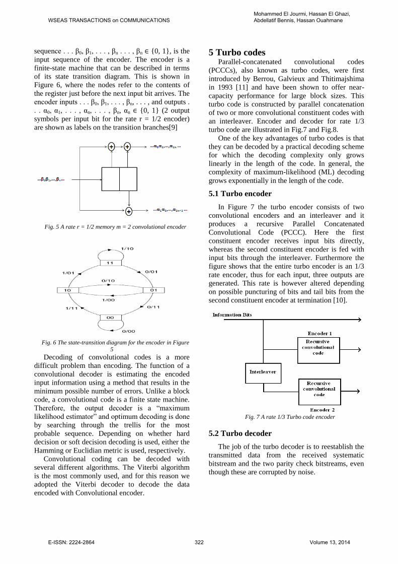
5.1 Turbo encoder
In Figure 7 the turbo encoder consists of two
convolutional encoders and an interleaver and it
produces a recursive Parallel Concatenated
Convolutional Code (PCCC). Here the first
constituent encoder receives input bits directly,
whereas the second constituent encoder is fed with
input bits through the interleaver. Furthermore the
figure shows that the entire turbo encoder is an 1/3
rate encoder, thus for each input, three outputs are
generated. This rate is however altered depending
on possible puncturing of bits and tail bits from the
second constituent encoder at termination [10].
Fig. 7 A rate 1/3 Turbo code encoder
5.2 Turbo decoder
The job of the turbo decoder is to reestablish the
transmitted data from the received systematic
bitstream and the two parity check bitstreams, even
though these are corrupted by noise.
WSEAS TRANSACTIONS on COMMUNICATIONSMohammed El Jourmi, Hassan El Ghazi, Abdellatif Bennis, Hassan Ouahmane
E-ISSN: 2224-2864 322 Volume 13, 2014

Fig. 8 A rate 1/3 Turbo code decoder
In a typical turbo decoding system (see Fig.8),
two decoders operate iteratively and pass their
decisions to each other after each iteration. These
decoders should produce soft-outputs to improve the
decoding performance. Such a decoder is called a
Soft-Input Soft- Output (SISO) decoder [10]. Each
decoder operates not only on its own input but also
on the other decoder’s incompletely decoded output.
In this paper the two SISO decoders used for
turbo decoding are Max-Log-Map.
6 LDPC codes LDPC codes were invented by Robert Gallager
[11] in his PhD thesis. Soon after their invention,
they were largely forgotten, and reinvented several
times for the next 30 years. Their comeback is one
of the most intriguing aspects of their history, since
two different communities reinvented codes similar
to Gallager's LDPC codes at roughly the same time,
but for entirely different reasons.
Fig. 9 An LDPC code
LDPC codes are linear codes obtained from
sparse bipartite graphs. Suppose that is a graph
with left nodes (called message nodes) and right
nodes (called check nodes). The graph gives rise to
a linear code of block length and dimension at
least in the following way: The coordinates
of the codewords are associated with the message
nodes. The codewords are those vectors
such that for all check nodes the sum of the
neighboring positions among the message nodes is
zero. Figure 9 gives an example.
The graph representation is analogous to a matrix
representation by looking at the adjacency matrix of
the graph: let be a binary -matrix in which
the entry is 1 if and only if the th check node
is connected to the th message node in the graph.
Then the LDPC code defined by the graph is the set
of vectors such that . The
matrix is called a parity check matrix for the code.
Conversely, any binary -matrix gives rise to a
bipartite graph between message and check
nodes, and the code defined as the null space of is
precisely the code associated to this graph.
Therefore, any linear code has a representation as a
code associated to a bipartite graph (note that this
graph is not uniquely defined by the code).
However, not every binary linear code has a
representation by a sparse bipartite graph. If it does,
then the code is called a low-density parity-check
(LDPC) code.
The sparsity of the graph structure is key
property that allows for the algorithmic efficiency of
LDPC codes.
6.1 Decoding Algorithms: Belief Propagation
Let us first start by describing a general class of
decoding algorithms for LDPC codes. These
algorithms are called message passing algorithms,
and are iterative algorithms. The reason for their
name is that at each round of the algorithms
messages are passed from message nodes to check
nodes, and from check nodes back to message
nodes. The messages from message nodes to check
nodes are computed based on the observed value of
the message node and some of the messages passed
from the neighboring check nodes to that message
node. An important aspect is that the message that is
sent from a message node to a check node must
not take into account the message sent in the
previous round from to . The same is true for
messages passed from check nodes to message
nodes.
One important subclass of message passing
algorithms is the belief propagation algorithm. This
algorithm is presented in Gallager's work, and it is
also used in the Artificial Intelligence community.
The messages passed along the edges in this
algorithm are probabilities, or beliefs. More
precisely, the message passed from a message node
to a check node is the probability that has a
WSEAS TRANSACTIONS on COMMUNICATIONSMohammed El Jourmi, Hassan El Ghazi, Abdellatif Bennis, Hassan Ouahmane
E-ISSN: 2224-2864 323 Volume 13, 2014

certain value given the observed value of that
message node, and all the values communicated to
in the prior round from check nodes incident to
other than . On the other hand, the message passed
from to is the probability that has a certain
value given all the messages passed to in the
previous round from message nodes other than .
7 Simulation model and system
specifications
This section is devoted to the description of the
simulation model, and presents the main
characteristics and specifications of the proposed
system.
Fig. 10 Overall Simulation Block Diagram
Figure 10 illustrates the overall simulation
model. Binary input signal to the system is
converted to symbol stream after passing through
the encoder. The frequency domain spreading is
done by using signature sequence of length 32 in the
CDMA transmitter. Up-converter is capable of
outputting its carrier at the desired RF frequency.
Signal is amplified with HPA before being
transmitted through the transmission channel. LNA
amplify very weak signals captured by the VSAT
antenna. Down-converter converts the desired signal
band to a convenient IF frequency for digitization.
Despreading in the CDMA receiver, demodulation
is done before passing through the decoder. The
original binary data is recovered after passing
through the decoder [8]. The parameters that we use
in our simulation are as follows:
TABLE 1: GENERAL INFORMATION
Satellite orbit radius 42242 km
Earth radius 6370 km
Distance from the VSAT to
satellite 38054 km
Free space loss 206.1 dB
Speed of light, c 3.108 ms-1
Boltzmann’s constant -228.6 dBJK-1 (=1.38 ×
10−23J/K)
TABLE 2: VSAT PARAMETERS
up-link frequency 14.25 GHz
VSAT HPA output power
1 W
Antenna diameter 1.2 m
Antenna gain 42.84 dBi
EIRP 42.84 dBW
VSAT latitude 45.5° N
VSAT longitude 9.5° E
Elevation angle 37.56°
Azimuth angle 183.5°
TABLE 3: SATELLITE PARAMETERS
Satellite figure of merit
-1 dB/K
satellite receiver effective
input noise temperature 500 K
Satellite antenna noise
temperature 290 K
uplink system noise
temperature 790 K
Power Flux density -119.22
Transponder bandwidth 54 MHz
Satellite antenna gain 31 dBi
Sub-satellite point longitude 7° E
C/ in up-link 64.34 dBHz
8 Results and discussion
In this simulation the performance results of
VSAT MC-CDMA system are obtained for uncoded
system and coded system with different channel
coding schemes and by using Binary Phase Shift
Keying modulation over Rayleigh channel. In this
WSEAS TRANSACTIONS on COMMUNICATIONSMohammed El Jourmi, Hassan El Ghazi, Abdellatif Bennis, Hassan Ouahmane
E-ISSN: 2224-2864 324 Volume 13, 2014

simulation the number of sub-carriers equals the
number of chips of the spreading code, the
maximum number of users is 32 users (full loading)
and the code length of spreading code is 32 chips.
8.1 Performance of uncoded VSAT MC-
CDMA system
Fig.11 Performance of uncoded VSAT MC-CDMA system (for
single, 8, 16 and 32 users)
Figure 11 shows the performance of VSAT MC-
CDMA system over Rayleigh channel for single, 8,
16 and 32 users. As seen in the figure, we can see
that the difference of performance curves is due to
the difference in number of active users in the
network. It is observed that the performance
obtained in the single-user case was better in
comparison with those of 8, 16 and 32 users. We
can also note that the performance is not very good
without coding, and it degrades rapidly as the total
number of users increase.
For different number of users the BER
performance achieves up to . For single user
the is beyond 19 dB and for half loading (16
users) the is beyond 38 dB. For full loading
(32 users) the is beyond 43 dB.
8.2 Performance of VSAT MC-CDMA
system using convolutional code
The simulation results of the system using
convolutional coding over Rayleigh channel are
shown in Figure 12. The decoder type used for
convolutional coding is the Viterbi decoder with
code rate
.
Fig.12 Performance of VSAT MC-CDMA system using
Convolutional code (for single, 8, 16 and 32 users)
We analyse the results of the Figure 12, we note
that the use of convolutional coding significantly
improves the performance of VSAT MC-CDMA.
Indeed, for 32 users active in the network, we notice
that there is an additional gain of 9 dB offered for a
bit error rate .
8.3 Performance of VSAT MC-CDMA
system using Turbo codes To evaluate the performance of the system using
turbo coding in a multipath environment, we used
the SISO decoder, which is carried out by using the
Max-Log-Map algorithm. In this simulation we
stopped at 3th iteration since there is no additional
improvement in term of BER for further iterations.
Fig.13 Performance of VSAT MC-CDMA system using Turbo
codes (For Single, 8, 16 and 32 users)
0 5 10 15 20 25 30 35 40 45 5010
-6
10-5
10-4
10-3
10-2
10-1
100
Eb/No (dB)
Bit
Erro
r R
ate
(B
ER
)
uncoded VSAT MC-CDMA system over Rayleigh channel
Single user
8 users
16 users
36 users
0 5 10 15 20 25 30 3510
-6
10-5
10-4
10-3
10-2
10-1
100
Eb/No (dB)
Bit
Erro
r R
ate
(B
ER
)
VSAT MC-CDMA system with Convolutional code Over Rayleigh channel (code rate R=1/3)
Single user
8 users
16 users
32 users
0 5 10 15 20 25 3010
-7
10-6
10-5
10-4
10-3
10-2
10-1
100
Eb/No (dB)
Bit
Erro
r R
ate
(B
ER
)
VSAT MC-CDMA system with Turbo codes (3rd iter) over Rayleigh channel
Single user
8 users
16 users
32 users
WSEAS TRANSACTIONS on COMMUNICATIONSMohammed El Jourmi, Hassan El Ghazi, Abdellatif Bennis, Hassan Ouahmane
E-ISSN: 2224-2864 325 Volume 13, 2014

On figure 13 we show the results of the third
iteration obtained by the simulation of VSAT MC-
CDMA system, for a variation of the active users
number in the network. As can be observed, for a
full loading of the network and for a bit error rate of
, the iterative process provides a gain of
approximately 6 dB compared with the performance
of the system using convolutional coding (for a
similar number of users).
We can conclude that the performance of VSAT
MC-CDMA system has been improved when the
iterative turbo coding is used. The latter has
provided advantageous performance compared to
convolutional coding system, but in terms of
complexity, the iterative turbo decoding is more
complex compared to Viterbi decoding.
8.4 Performance of VSAT MC-CDMA
system using LDPC codes
The decoder algorithm used for LDPC is the
Belief Propagation with
. For different
number of active users in the network, the
performance results of the envisaged system, using
LDPC codes are showed in the figure 14.
Fig.14 Performance of VSAT MC-CDMA system using LDPC
codes (For Single, 8, 16 and 32 users)
In our simulation we stopped at 20th iteration
since there is no additional improvement in term of
BER for further iterations. In comparison with
previously reported results, we note that system
using LDPC coding showed better performance
compared to the system adopting the Turbo coding.
In the figure it is observed that for a bit error rate of
the system opting to the LDPC coding provides an
additional gain of 2 dB (for 32 users) compared with
coded system by Turbo code (for similar number of
users). In terms of BER, the performance of system
using LDPC reaches a lower value compared with
that achieved by the use of Turbo coding. In terms
of complexity, we find that the LDPC decoding
system is less complex compared to Turbo decoding
process.
8.5 Performance of VSAT MC-CDMA
system using the predistortion technique
This part is devoted to the description of the
linearization technique principle adapted to the
power amplifier adopted by VSATs stations, and
analysis of simulation results obtained by the VSAT
MC-CDMA system using LDPC codes in
conjunction with the predistortion process.
8.5.1 Predistortion technique
SSPA and TWTA are two types of power
amplifiers which are widely used by the VSAT
networks. TWTA is mostly used for high power
satellite transmitters (in this case, we talk about the
HUB stations), while SSPA is used in many other
applications requiring stations with small antenna
(as the case of VSATs stations).
To compensate the effect of non-linearity of the
High Power Amplifier (HPA), we introduced in the
communication system a predistortion technique
which is adapted to the SSPA amplifier.
The complex output of RF with non-linear
distortion can be expressed as:
.exp Φ ρ tz t A t j t (17)
Where and represent the conversion
AM/AM and AM/PM of the nonlinear amplifier.
The SSPA’s AM/AM and AM/PM can be
captured by [12][13]:
2 1/2
0[1 ( / ) ]p p
tA t
t A
(18)
Φ 0t (19)
A is the maximum output amplitude and the
parameter controls the smoothness of the
transition from the linear region to the limiting
region [13].
In general, the predistortion technique principle
is illustrated in the Figure 15.
0 5 10 15 20 25 3010
-7
10-6
10-5
10-4
10-3
10-2
10-1
100
Eb/No (dB)
Bit
Erro
r R
ate
(B
ER
)
VSAT MC-CDMA system with LDPC codes (20 iter) over Rayleigh channel
LDPC Single user
LDPC 8 users
LDPC 16 users
LDPC 32 users
WSEAS TRANSACTIONS on COMMUNICATIONSMohammed El Jourmi, Hassan El Ghazi, Abdellatif Bennis, Hassan Ouahmane
E-ISSN: 2224-2864 326 Volume 13, 2014

Fig.15 predistortion technique principle
When a PD transformation is applied to the
signal, this last will pass through the HPA in order
to be amplified and the nonlinearity effects of the
amplifier will be compensated. For the predistortion
technique, the input-output relationship is given by
the following expressions:
1[ ( )]r t A t (20)
Φ[ ( )] t t r t (21)
The linearization technique chosen in our study
is the predistortion described in [14]. Therefore by
inversion of we get the expression of
corresponding to the SSPA amplifier.
2 1/2
0
( )[1 ( / ) ]p p
tr t
t A
(22)
8.5.2 Simulation results of VSAT MC-CDMA
with predistortion technique
To highlight the improvement provided by the
predistortion technique in the VSAT MC-CDMA
system using the LDPC coding, we have shown in
Figure 16 the performance curves of the system with
and without integrating the predistortion.
Fig.16 Performance of VSAT MC-CDMA system using LDPC
codes and predistortion technique (For 32 users)
In Figure 16, we can observe that for a BER=10-5
the system using LDPC coding provides an
additional gain of 2 dB compared to the system
coded by turbo codes. We can notice also that, after
the integration of LDPC coding in communication
chain, system performance reaches a lower value of
BER compared to that reached by the adoption of
Turbo coding.
In the figure above, we observe that the adoption
of the predistortion technique improves the system
performance in terms of bit error rate. Indeed, for a
BER of 10-5
, the system adopting the LDPC codes
in conjunction with the predistortion technique
provides a gain of about 1 dB compared to the
system using the LDPC codes without predistortion
process.
In figure 17 we presented the performance of the
communication system using LDPC codes for a
variation of the size of the code blocks.
In general, we note that the performance
gradually improved when the block code size
increases. For large blocks of code, LDPC coding
can result very close to the Shannon limit
performance. But, we find that increasing the code
block size leads to increased complexity of the
decoding system.
Fig.17 impact of the block length on performance of VSAT MC-
CDMA system (For 32 users)
9 Conclusion
In this paper, the performance in uplink of VSAT
MC-CDMA system has been investigated by using
the Ku band and the most popular type of multiple
access technique, Code Division Multiple Access
10 12 14 16 18 20 22 24 26 28 30 3210
-6
10-5
10-4
10-3
10-2
10-1
100
Eb/No (dB)
Bit
Erro
r R
ate
(B
ER
)
VSAT MC-CDMA System with LDPC (20 iter) and PD over Rayleigh Channel
Turbo-codes (32 users)
LDPC without PD (32 users)
LDPC with PD (32 users)
14 16 18 20 22 24 2610
-7
10-6
10-5
10-4
10-3
10-2
10-1
100
Eb/No (dB)
Bit
Erro
r R
ate
(B
ER
)
VSAT MC-CDMA with LDPC and PD over Rayleigh channel (32 users)
LDPC (3072,1024)
LDPC (1536,512)
LDPC (768,256)
LDPC (384,128)
WSEAS TRANSACTIONS on COMMUNICATIONSMohammed El Jourmi, Hassan El Ghazi, Abdellatif Bennis, Hassan Ouahmane
E-ISSN: 2224-2864 327 Volume 13, 2014

(CDMA) combining with multicarrier transmission
system. To get the lower bit error rate, the most
common types of channel coding methods (LDPC
codes, Turbo codes and convolutional codes) are
used. To compensate the effect of the non-linearity
in the system, a predistortion technique adapted to
the SSPA amplifier was adopted. The results show
that the performance depends upon the number of
active users in the network and performance of
encoding/decoding mechanisms.
In conclusion, for a similar code rate we can see
that despite the performance offered by the coding
structures "Turbo and Convolutional" these coding
strategies are less reliable and efficient process
compared to LDPC coding. Because this mechanism
presented a great potential for improvement and
optimization. we can add that the increasing of the
code length improves performance but also
increases the complexity of the decoding system. it
was noted that the integration of the predistortion
technique further improves the performance of the
coded system.
References:
[1] Maral, G. 1996. VSAT Networks. New York: John
Wiley & Sons Ltd.
[2] Evans, B.G., Satellite Communication Systems, 3rd
ed., United Kingdom. The Institution of Electrical
Engineers, 1999.
[3] Elbert, B.R., The Satellite Communication Ground
Segment and Earth Station Handbook, Artech House,
2000.
[4] Elbert, B.R., Introduction to Satellite
Communication 3rd , Artech House, 2008.
[5] Moheb, H., C. Robinson, J. Kijeski, “Design and
Development of Co-Polarized Ku-band Ground
Terminal System for VSAT Application,” IEEE
Publications 0-7803-5639-X/99, pp. 2158-2161,
1999.
[6] H. E. Ghazi, “Allocation Algorithm for Optimizing
MC-CDMA Over Correlated Channel”accepted by
WSEAS Trans. On commun.2010.
[7] Q. Shi and M. Latva-Aho, “Performance analysis of
MC-CDMA in Rayleigh fading channels with
correlated envelopes and phases,” IEE Proc.
Commun., vol. 150, pp. 214–220, June 2003.
[8] M. El jourmi, “Performance analysis of channel
coding in satellite communicationbased on VSAT
Network and MC-CDMA scheme” WSEAS Trans.
on commun., issue 5, vol 12, May 2013.
[9] Q. Shi and M. Latva-Aho, “Performance analysis of
MC-CDMA in Rayleigh fading channels with
correlated envelopes and phases,” IEE Proc.
Commun., vol. 150, pp. 214–220, June 2003.
[10] 3GPP, \3GPP TS 45.003 V7.5.0." Internet, 2008.
[11] Peter Clements, Paul Nettle, and Ryan Gallagher.
Parity volume set specification 2.0, May 11th 2003.
[12] A. N. D’Andrea, V. Lottici and R. Reggiannin, «Nonlinear Predistortion of OFDM Signals over
Frequency-Selective Fading Channels», IEEE
Transactions on Communications. Vol. 49. N° 5. pp.
837-843. 2001.
[13] R. zayani, S. Zid, R. Bouallegue, « Simulateur des
non-linéarités HPA sur un système OFDM » OHD
Conference, septembre 2005.
[14] P.B. Kenington, "High-linearity RF amplifier
design", Artech house, pp.351-423, 2000.
WSEAS TRANSACTIONS on COMMUNICATIONSMohammed El Jourmi, Hassan El Ghazi, Abdellatif Bennis, Hassan Ouahmane
E-ISSN: 2224-2864 328 Volume 13, 2014