Embed Size (px)
Citation preview
PERFORMANCE OF A DAYLIGHT REDIRECTING GLASS SHADING SYSTEM DEMONSTRATION IN AN OFFICE BUILDING
David Appelfeld1,*, Svend Svendsen1 and Steen Traberg-Borup2
1Technical University of Denmark, Department of Civil Engineering, Section of Building Physics and Services
2 SBi, Danish Building Research Institute, Denmark *Corresponding Author: [email protected]
ABSTRACT This paper evaluates the daylighting performance of a prototype external dynamic integrated shading and light redirecting system. The demonstration project was carried out on a building with an open-plan office. The prototype and original façades were placed on the same floor with the same orientation and similar surroundings. The existing façade was used as the reference for measurements and simulations. The focus of this research project was to employ available simulation tools for the system performance evaluation. This was accompanied by measurements of the daylight conditions in the investigated space. The prototype system improved daylighting conditions compared to the existing shading system.
INTRODUCTION The growing demand for energy savings, money savings, and seeking new innovative technologies is the motivation of the research. Available simulation programs cannot easily evaluate unique complex fenestration systems using standardized methods, since they are mostly created to evaluate specific solutions. The complexity of the assessment can be seen from many perspectives such as energy impact, shape, material, cost and operating cost. Therefore, we have to use more generic and versatile simulation programs and techniques to have the possibility to evaluate the performance impact. Consequently, by the obtained knowledge it is possible to do an evaluation on more standardized level for future solution development. Additionally, the need to cut down energy consumption of buildings has led to buildings that are increasingly insulated against heat losses. It has been emphasized in many publications and studies that buildings consume around 40% of overall energy used globally (EU, 2010). Therefore cutting the energy used by buildings is of major interest in this study. The solar gains in the buildings are twofold. The glazed areas in the new office buildings are getting larger, which increases solar gains during the cold periods of year and increase working plane illuminance, however during the warmer season the over-glazed areas can cause overheating problems or
cause glare. Using energy to remove excessive heat is costly and may completely wash out the energy saving effect of utilizing solar energy for space heating. In addition, the solar gains in newly built buildings are considered as significant source of heating. Therefore, the solar gains have to be included in the total energy demand of a building (EN 15603, 2008). Hence, transparent parts of the building envelopes serve several functions. First, they must provide enough light transmittance, or daylight utilization, which is also the main purpose behind this article. Second, they should provide sufficient solar energy transmittance during cold months. Third, they should prevent indoor space from overheating during warmer months by shading excessive solar gains without blocking the view and the solar energy gains, as has been a pitfall of current shading systems. Since a significant portion of energy in the buildings is devoted to lighting and ventilation, daylight and cooling have a large energy saving potential for advanced solar shading systems (Lee, 2009).
BACKGROUND Based on previous studies, a shading system with light redirecting glass lamellas with a solar control surface was built as demonstration (Laustsen et al., 2008; Iversen et al., 2009). The shading system removes the drawback of the current systems, which partly block views, while shade excessive solar gains and redirect daylight into the back of deep office rooms where daylight is desirable. The investigation was based on the full-scale demonstration project and is accompanied by computer modelling. The simulation model can be used for various buildings, since it is not feasible to build a demonstration for all possible buildings and shading scenarios. The evaluation of the performance of the shading system by simulations is the objective and the central point of the research. The main focuses are to evaluate the daylighting performance of the demonstrated system, based on simulations and measurements of illuminance readings at working plane and comparing it with the reference system. The scope of this study is therefore not to evaluate the visual comfort aspects like glare, that might be caused by the shading system.
Proceedings of Building Simulation 2011: 12th Conference of International Building Performance Simulation Association, Sydney, 14-16 November.
- 1406 -
EXPERIMENT Demonstration building
The demonstration building equipped with a prototype of an external dynamic integrated shading and light redirecting system is located in Humlebaek 30km north of Copenhagen, Denmark (55.96N -12.49E). The building was refurbished from a production facility to an open space office, which caused deep open office space with working spaces far away from the façade. The building is one floor high and the open façade with 2.26m high windows is oriented 11° west by south. The whole building has dimensions of 66m x 28m with the longer side oriented south. The surrounded landscape is relatively flat without any big trees or high buildings that might shade the investigated façade. However, the opposite building blocks the open horizon. The open space office has a room depth up to 14m. The floor plan of building is on Figure 1. The building/façade layout allows preservation of a reference office space with the same orientation and similar layout as the investigated space for comparison of daylighting conditions. The two spaces were fitted with same set of illuminance sensors to monitor the actual conditions. The open space is divided by small meeting rooms, which are separated by the partitions. The partitions are partially from wood and glass, which allow better penetration of light into the space. The test and reference areas are both approximately 9.5m wide and 14m deep with ceiling height of 3.45m. The building has windows on the south and west façades with columns between individual windows. The window openings are 1.98m wide and 2.26m high with windowsill 0.75m above the floor. The reflectance of the surfaces in the building and outdoors were measured by illuminance meter in order to have identical surface properties for the measurements and simulation model. The visible reflectance measurements were averaged from three values measured on different places of the surface, values are presented in Table 1. The roughness and specularity of surfaces for the model were neglected.
Table 1
Building model surface reflectance values
SURFACE VISIBLE REFLECTANCE (Rvis) Floor 20.5% White walls 89.3% Wooden partitions 32.6% Ceiling 89.9%
The shading system The major difference between the new and original shading system is that newly installed lamellas rotate in an opposite direction, compared to the conventional shading system. The outer edge moves
upwards and the upper surface goes towards the façade when the system is closing. Each window consists of eight horizontal 330mm wide lamellas. The rotation directions of the lamellas are demonstrated on Figure 2. Four uppermost lamellas rotated in toward the façade and the rest of lamellas rotate in opposite direction out of the facade. This strategy allows the upper part of the system to redirect and shade while the lower part acts as a traditional shading system which allows to see outside. The new system is made from highly reflective solar control coated glass to redirect daylight into the back of the room. New lamellas were produced by Saint Gobain Glass (SGG) and the used glass was Antelio Silver 10mm, with light reflectance of 31%. The original lamellas were made from Parasol Green 8mm with light reflection of 6%, made by SGG, with white frit covering 55% of the surface. The properties of shading glass, glazing and glass partitions are listed in Table 2.
Table 2 Centre-of-glass properties of glass used in the model
GLASS VIS. TRANSMITTANCE (Tvis) Glazing 73% Glass partitions 88% New glass lamellas 66% Old glass lamellas 68% (without frit)
Shading control strategy The shading strategy of the system was based on results from the previous investigation, location and sun position. The most effective daylight redirecting position is when the lamellas are in the position of 30° towards the façade (Laustsen et al., 2008). The lamellas stay in this position when the sky is overcast or the total horizontal illuminance is lower than threshold of 25 klux for longer than 10min. The time delay prevents excessive opening and closing the shading system, which could irritate office occupants. The threshold for moving lamellas back to the redirecting stage, in the case that the daylighting conditions are poor, was set to 17.5 klux with time offset of at least 20min. This assumption was based on the illuminance under clear, overcast and intermediate sky. The redirecting position was 30° all year around expect May and June when the position was set to 25° down towards the façade to avoid direct reflection from the lamellas’ surfaces to the occupants’ faces. The system had three possible positions:
• Redirecting position 30° (25°) • Open position 0° • Close position 90°
In addition, the redirecting position was designed to avoid reflection of direct sunlight from the lamellas surfaces when the sun is partially behind clouds.
Proceedings of Building Simulation 2011: 12th Conference of International Building Performance Simulation Association, Sydney, 14-16 November.
- 1407 -
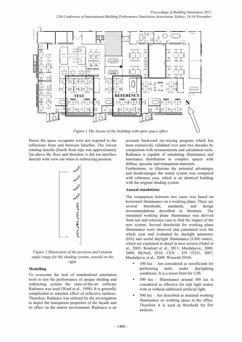
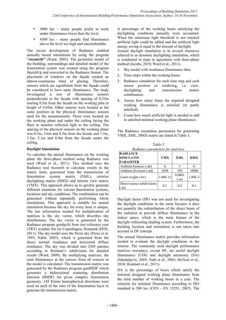
Figure 1 The layout of the building with open space office. Hence the space occupants were not exposed to the reflections from and between lamellas. The lowest rotating lamella (fourth from top) was approximately 2m above the floor and therefore it did not interface directly with view out when in redirecting position.
Figure 2 Illustration of the position and rotation
angle range for the shading system, outside on the right.
Modelling To overcome the lack of standardized simulation tools to test the performance of unique shading and redirecting system the state-of-the-art software Radiance was used (Ward et al., 1998). It is generally complicated to simulate effect of reflective surfaces. Therefore, Radiance was utilized for the investigation to depict the transparent properties of the façade and its effect on the indoor environment. Radiance is an
accurate backward ray-tracing program which has been extensively validated over past two decades by comparison with measurements and calculation tools. Radiance is capable of simulating illuminance and luminance distribution in complex spaces with diffuse, specular and transparent materials. Furthermore, to illustrate the potential advantages and disadvantages the tested system was compared with reference case, which is an identical building with the original shading system.
Annual simulations
The comparison between two cases was based on horizontal illuminance on a working plane. There are several thresholds, standards, and design recommendations described in literature. The simulated working plane illuminance was derived from test and reference case to find the impact of the new system. Several thresholds for working plane illuminance were observed and cumulated over the whole year and evaluated by daylight autonomy (DA) and useful daylight illuminance (UDI) matrix, which are explained in detail in next section (Nabil et al., 2005; Reinhart et al., 2011; Mardaljevic, 2000, 2009; McNeil, 2010; CEN - EN 15251, 2007; Mardaljevic et al., 2009, Wienold 2010).
• 100 lux – Are considered as insufficient for performing tasks under daylighting conditions. It is a lower limit for UDI.
• 300 lux – Illuminance around 300 lux is considered as effective for task light source with or without additional artificial light.
• 500 lux – Are described as minimal working illuminance on working space in the office. Therefore it is used as threshold for DA analysis.
TEST REFERENCE
N
Proceedings of Building Simulation 2011: 12th Conference of International Building Performance Simulation Association, Sydney, 14-16 November.
- 1408 -
• 3000 lux – many people prefer to work under illuminance lower then the level.
• 4500 lux – many people find illuminance above the level too high and uncomfortable.
The recent development of Radiance enabled annually based simulations by using the program “rtcontrib” (Ward, 2005). The geometric model of the building, surroundings and detailed model of the fenestration system was created using the program SketchUp and converted to the Radiance format. The placement of windows on the façade created an almost-continuous band of glazing. Therefore, sensors which are equidistant from the façade could be considered to have same illuminance. The study investigated a row of illuminance sensors perpendicular to the facade with spacing of 0.25m starting 0.5m from the facade on the working plan in height of 0.85m. Other sensors were located at the same position as the physical illuminance sensors used for the measurements. These were located on the working plane and under the ceiling facing the floor to monitor reflected light to the ceiling. The spacing of the physical sensors on the working plane was 0.5m, 3.6m and 8.5m from the facade and 1.5m, 3.3m, 5.1m and 6.9m from the facade under the ceiling.
Daylight Simulation To calculate the annual illuminance on the working plane the three-phase method using Radiance was used (Ward et al., 2011). This method uses the Radiance tool rtcontrib to calculate results in the matrix form, generated from the transmission of fenestration system matrix (XML), exterior daylighting matrix (DMX) and interior view matrix (VMX). This approach allows us to quickly generate different situations for various fenestration systems, locations and sky conditions. The combination can be generated without repeatedly performing whole simulations. This approach is suitable for annual simulation because the sky for every hour is unique. The last information needed for multiplication of matrixes is the sky vector, which describes sky distributions. The sky vector is generated by the Radiance program gendaylit from test reference year (TRY) weather file for Copenhagen, Denmark (DOE, 2011). The sky model uses the Perez sky (Perez et al, 1993; Nabil, 2005), which is generated from the direct normal irradiance and horizontal diffuse irradiance. The sky was divided into 2305 patches according to Reinhart’s subdivision for detailed results (Ward, 2009). By multiplying matrixes, the total illuminance at the sensors from all sources in the model is calculated. The transmission matrix was generated by the Radiance program genBSDF which generates a bidirectional scattering distribution function (BSDF) for given complex fenestration geometry. 145 Klems hemispherical directions were used on each of the sites of the fenestration layer to generate the transmission matrix.
A percentage of the working hours satisfying the daylighting conditions annually were accounted. When the minimum light threshold is not reached artificial light could be added and the artificial light energy saving is equal to the amount of daylight. Annual daylight simulation is in several resources referred to as dynamic daylighting simulation, which is conducted in steps in agreement with three-phase method (Jacobs, 2010; Ward et al., 2011). 1. Sky model with irradiance/illuminance data. 2. Time steps within the working hours. 3. Radiance simulation for each time step and each
sensor position or rendering, i.e. view, daylighting and transmission matrix combination.
4. Assess how many times the required designed working illuminance is satisfied (or partly satisfied).
5. Count how much artificial light is needed to add to satisfied minimal working plane illuminance.
The Radiance simulation parameters for generating VMX, XML, DMX matrix are listed in Table 3.
Table 3
Radiance parameters for matrixes RADIANCE SIMULATIN PARAMTER
VMX XML DMX
Ambient bounces (-ab) 6 3 6 Ambient divisions (-ad) 2048 350 10000
Limit weight (-lw) 1.00E-12 0.0001 (-st) 1.00E-3
Direct source subdivisions (-ds) 0.1 0.2 0.1
Daylight factor (DF) was not used for investigating the daylight conditions in the room because it does not quantify the redistribution of the direct beam of the radiation to provide diffuse illuminance in the indoor space, which is the main feature of the daylight redirecting shading system. Furthermore, the building location and orientation is not taken into account in DF concept. The annual illuminance matrix provides information needed to evaluate the daylight conditions in the interior. The commonly used daylight performance matrixes nowadays, except DF, are useful daylight illuminance (UDI) and daylight autonomy (DA) (Mardaljevic, 2005; Nabi et al., 2005; McNeal et al., 2010; Reinhart et al., 2011). DA is the percentage of hours which satisfy the minimal designed working plane illuminance from the total number of working hours in a year. The criterion for minimal illuminance according to ISO standard is 500 lux (CEN - EN 15251, 2007). The
Proceedings of Building Simulation 2011: 12th Conference of International Building Performance Simulation Association, Sydney, 14-16 November.
- 1409 -
commonly used design horizontal working illuminance is between 300 – 500 lux. The UDI matrix quantifies when the daylight is perceived as useful for occupants of the space. It is calculated as percentage of the occupied working hours when the illuminance on the working plan is between the lower and upper thresholds. 100 lux is considered as the lower illuminace level. The upper level is not clearly defined and differs between studies and publications. Therefore several levels was recorded in this study. As the threshold, when the occupants may feel uncomfortable, 4500 lux was used. According to (Wienold, 2010) 30% of people find horizontal illuminance above 4500 as dissatisfying. Midrange between 100 lux and 4500 lux may be considered as usable for most of the occupants. Some subjects may consider the values in this range as uncomfortable, however values should not be considered as not useful values since every subject perceive different illuminance levels differently (Wienold, 2010; Mardaljevic et al., 2009).
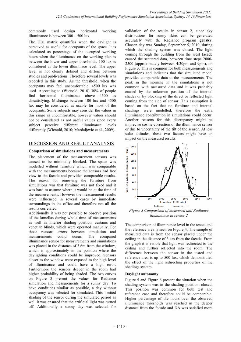
DISCUSSION AND RESULT ANALYSIS Comparison of simulations and measurements The placement of the measurement sensors was caused to be minimally blocked. The space was modelled without furniture which was comparable with the measurements because the sensors had free view to the façade and provided comparable results. The reason for removing the furniture from simulations was that furniture was not fixed and it was hard to assume where it would be at the time of the measurements. However the measurement results were influenced in several cases by immediate surroundings in the office and therefore not all the results correlated. Additionally it was not possible to observe position of the lamellas during whole time of measurements as well as interior shading position, curtains and venetian blinds, which were operated manually. For those reasons errors between simulation and measurements could occur. The compared illuminance sensor for measurements and simulations was placed in the distance of 3.6m from the window, which is approximately in the position where the daylighting conditions could be improved. Sensors closer to the window were exposed to the high level of illuminance and could have a high error. Furthermore the sensors deeper in the room had higher probability of being shaded. The two curves on Figure 3 present the values for Radiance simulation and measurements for a sunny day. To have conditions similar as possible, a day without occupancy was selected for simulated. This limited shading of the sensor during the simulated period as well it was ensured that the artificial light was turned off. Additionally a sunny day was selected for
validation of the results in sensor 2, since sky distributions for sunny skies can be generated accurately with the Radiance program gensky. Chosen day was Sunday, September 5, 2010, during which the shading system was closed. The light coming through the building from the west facade caused the scattered data, between time steps 2000-2500 (approximately between 4:30pm and 9pm), on Figure 3. This is common for both measurements and simulations and indicates that the simulated model provides comparable data to the measurements. The peak in the morning in the simulations is not common with measured data and it was probably caused by the unknown position of the internal shades or by blocking of the direct or reflected light coming from the side of sensor. This assumption is based on the fact that no furniture and internal shadings were modelled, therefore the extra illuminance contribution in simulations could occur. Another reasons for this discrepancy might be imprecise cosine-correction of the illuminance sensor or due to uncertainty of the tilt of the sensor. At low solar altitudes, these two factors might have an impact on the measured results.
Figure 3 Comparison of measured and Radiance
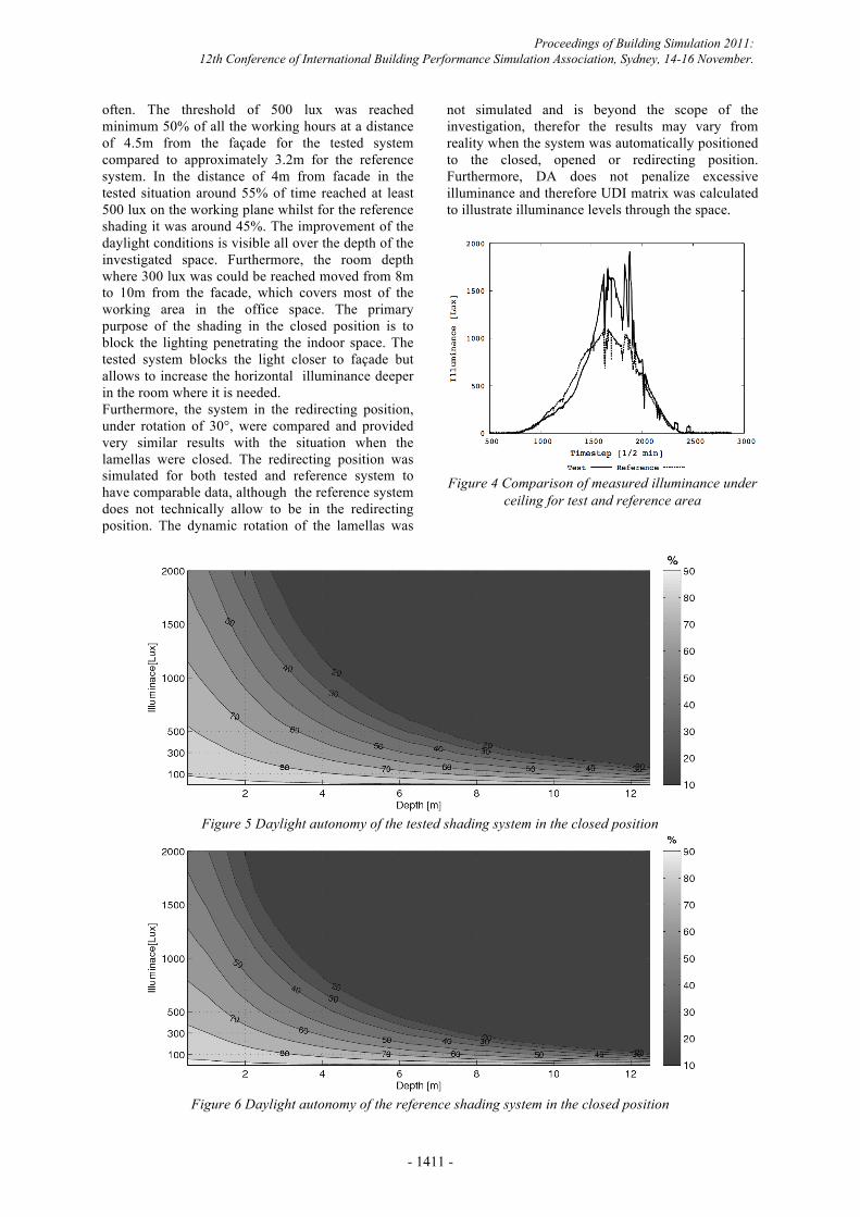
illuminance in sensor 2 The comparison of illuminance level in the tested and the reference area is seen on Figure 4. The sample of measured data is from the sensor placed under the ceiling in the distance of 3.4m from the façade. From the graph it is visible that light was redirected to the ceiling and further reflected into the room. The difference between the sensor in the tested and reference area is up to 500 lux, which demonstrated the effect of the light redirecting properties of the shadings system.
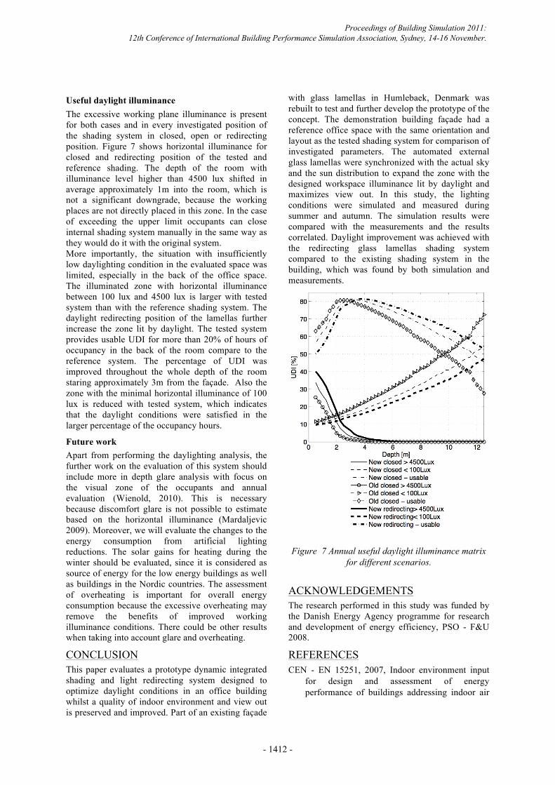
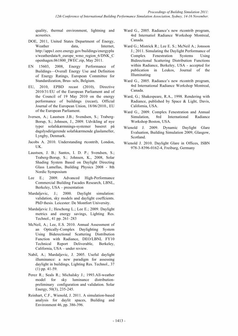
Daylight autonomy Figure 5 and Figure 6 present the situation when the shading system was in the shading position, closed. This position was common for both test and reference case and therefore could be comparable. Higher percentage of the hours over the observed illuminance thresholds was reached in the deeper distance from the facade and DA was satisfied more
Proceedings of Building Simulation 2011: 12th Conference of International Building Performance Simulation Association, Sydney, 14-16 November.
- 1410 -
often. The threshold of 500 lux was reached minimum 50% of all the working hours at a distance of 4.5m from the façade for the tested system compared to approximately 3.2m for the reference system. In the distance of 4m from facade in the tested situation around 55% of time reached at least 500 lux on the working plane whilst for the reference shading it was around 45%. The improvement of the daylight conditions is visible all over the depth of the investigated space. Furthermore, the room depth where 300 lux was could be reached moved from 8m to 10m from the facade, which covers most of the working area in the office space. The primary purpose of the shading in the closed position is to block the lighting penetrating the indoor space. The tested system blocks the light closer to façade but allows to increase the horizontal illuminance deeper in the room where it is needed. Furthermore, the system in the redirecting position, under rotation of 30°, were compared and provided very similar results with the situation when the lamellas were closed. The redirecting position was simulated for both tested and reference system to have comparable data, although the reference system does not technically allow to be in the redirecting position. The dynamic rotation of the lamellas was
not simulated and is beyond the scope of the investigation, therefor the results may vary from reality when the system was automatically positioned to the closed, opened or redirecting position. Furthermore, DA does not penalize excessive illuminance and therefore UDI matrix was calculated to illustrate illuminance levels through the space.
Figure 4 Comparison of measured illuminance under
ceiling for test and reference area
Figure 5 Daylight autonomy of the tested shading system in the closed position
Figure 6 Daylight autonomy of the reference shading system in the closed position
Proceedings of Building Simulation 2011: 12th Conference of International Building Performance Simulation Association, Sydney, 14-16 November.
- 1411 -
Useful daylight illuminance The excessive working plane illuminance is present for both cases and in every investigated position of the shading system in closed, open or redirecting position. Figure 7 shows horizontal illuminance for closed and redirecting position of the tested and reference shading. The depth of the room with illuminance level higher than 4500 lux shifted in average approximately 1m into the room, which is not a significant downgrade, because the working places are not directly placed in this zone. In the case of exceeding the upper limit occupants can close internal shading system manually in the same way as they would do it with the original system. More importantly, the situation with insufficiently low daylighting condition in the evaluated space was limited, especially in the back of the office space. The illuminated zone with horizontal illuminance between 100 lux and 4500 lux is larger with tested system than with the reference shading system. The daylight redirecting position of the lamellas further increase the zone lit by daylight. The tested system provides usable UDI for more than 20% of hours of occupancy in the back of the room compare to the reference system. The percentage of UDI was improved throughout the whole depth of the room staring approximately 3m from the façade. Also the zone with the minimal horizontal illuminance of 100 lux is reduced with tested system, which indicates that the daylight conditions were satisfied in the larger percentage of the occupancy hours.
Future work Apart from performing the daylighting analysis, the further work on the evaluation of this system should include more in depth glare analysis with focus on the visual zone of the occupants and annual evaluation (Wienold, 2010). This is necessary because discomfort glare is not possible to estimate based on the horizontal illuminance (Mardaljevic 2009). Moreover, we will evaluate the changes to the energy consumption from artificial lighting reductions. The solar gains for heating during the winter should be evaluated, since it is considered as source of energy for the low energy buildings as well as buildings in the Nordic countries. The assessment of overheating is important for overall energy consumption because the excessive overheating may remove the benefits of improved working illuminance conditions. There could be other results when taking into account glare and overheating.
CONCLUSION This paper evaluates a prototype dynamic integrated shading and light redirecting system designed to optimize daylight conditions in an office building whilst a quality of indoor environment and view out is preserved and improved. Part of an existing façade
with glass lamellas in Humlebaek, Denmark was rebuilt to test and further develop the prototype of the concept. The demonstration building façade had a reference office space with the same orientation and layout as the tested shading system for comparison of investigated parameters. The automated external glass lamellas were synchronized with the actual sky and the sun distribution to expand the zone with the designed workspace illuminance lit by daylight and maximizes view out. In this study, the lighting conditions were simulated and measured during summer and autumn. The simulation results were compared with the measurements and the results correlated. Daylight improvement was achieved with the redirecting glass lamellas shading system compared to the existing shading system in the building, which was found by both simulation and measurements.
Figure 7 Annual useful daylight illuminance matrix for different scenarios.
ACKNOWLEDGEMENTS The research performed in this study was funded by the Danish Energy Agency programme for research and development of energy efficiency, PSO - F&U 2008.
REFERENCES CEN - EN 15251, 2007, Indoor environment input
for design and assessment of energy performance of buildings addressing indoor air
Proceedings of Building Simulation 2011: 12th Conference of International Building Performance Simulation Association, Sydney, 14-16 November.
- 1412 -
quality, thermal environment, lightning and acoustics.
DOE, 2011, United States Department of Energy, Weather data, Internet, http://apps1.eere.energy.gov/buildings/energyplus/weatherdata/6_europe_wmo_region_6/DNK_Copenhagen.061800_IWEC.zip, May 2011.
EN 15603, 2008, Energy Performance of Buildings—Overall Energy Use and Definition of Energy Ratings, European Committee for Standardization, Brus- sels, Belgium.
EU, 2010, EPBD recast (2010), Directive 2010/31/EU of the European Parliament and of the Council of 19 May 2010 on the energy performance of buildings (recast), Official Journal of the European Union, 18/06/2010., EU of the European Parliament.
Iversen, A.; Laustsen J.B.; Svendsen, S.; Traberg-Borup, S.; Johnsen, J., 2009. Udvikling af nye typer solafskærmnings-systemer baseret på dagslysdirigerende solafskærmende glaslameller, Lyngby, Denmark.
Jacobs A. 2010. Understanding rtcontrib, London, UK.
Laustsen, J. B.; Santos, I. D. P.; Svendsen, S.; Traberg-Borup, S.; Johnsen, K., 2008, Solar Shading System Based on Daylight Directing Glass Lamellas, Building Physics 2008 - 8th Nordic Symposium
Lee E.; 2009. Advanced High-Performance Commercial Building Facades Research, LBNL, Berkeley, USA – presentation
Mardaljevic, J.; 2000. Daylight simulation: validation, sky models and daylight coeffcients. PhD thesis. Leicester: De Montfort University.
Mardaljevic J.; Heschong L.; Lee E.; 2009. Daylight metrics and energy savings, Lighting Res. Technol., 41 pp. 261–283
McNeil, A.; Lee, E.S. 2010. Annual Assessment of an Optically-Complex Daylighting System Using Biderectional Scattering Distribution Function with Radiance, DEO/LBNL FY10 Technical Report Deliverable, Berkeley, California, USA – under review.
Nabil, A.; Mardaljevic, J. 2005. Useful daylight illuminance: a new paradigm for assessing daylight in buildings, Lighting Res. Technol., 37 (1) pp. 41-59.
Perez R.; Seals R.; Michalsky J.; 1993.All-weather model for sky luminance distribution-preliminary configuration and validation. Solar Energy, 50(3), 235-245.
Reinhart, C.F., Wienold, J. 2011. A simulation-based analysis for daylit spaces, Building and Environment 46, pp. 386-396.
Ward G., 2005. Radiance’s new rtcontrib program, 4rd Internatiol Radiance Workshop Montreal, Canada.
Ward G.; Mistrick R.; Lee E. S.; McNeil A.; Jonsson J.; 2011. Simulating the Daylight Performance of Complex Fenestration Systems Using Bidirectional Scattering Distribution Functions within Radiance, Berkeley, USA - accepted for publication in Leukos, Journal of the Illuminating
Ward G., 2005. Radiance’s new rtcontrib program, 4rd International Radiance Workshop Montreal, Canada.
Ward, G.; Shakespeare, R.A., 1998. Rendering with Radiance, published by Space & Light, Davis, California, USA.
Ward G., 2009. Complex Fenestration and Annual Simulation, 8rd International Radiance Workshop Boston, USA.
Wienold J. 2009. Dynamic Daylight Glare Evaluation, Building Simulation 2009, Glasgow, Scotland.
Wienold J. 2010. Daylight Glare in Offices, ISBN 978-3-8396-0162-4, Freiburg, Germany
Proceedings of Building Simulation 2011: 12th Conference of International Building Performance Simulation Association, Sydney, 14-16 November.
- 1413 -