Embed Size (px)
Citation preview
PERFORMANCE OF DIFFERENT MACH-ZEHNDER INTERFEROMETER
(MZI) STRUCTURES FOR OPTICAL MODULATOR
NUR HIDAYAH BINTI SULAIMAN
This Report Is Submitted In Partial Fulfillment of Requirements for The Bachelor
Degree of Electronic Engineering (Electronic Telecommunication)
Fakulti Kejuruteraan Elektronik dan Kejuruteraan Komputer
Universiti Teknikal Malaysia Melaka
June 2016


i
To Mama and Ayah.
To my sister, brothers and friends.
You all are my strongest bone.

ii
ACKNOWLEDGEMENT
All praise to Allah for my good health and well being without His permission, I
won’t be able to finish my journey until now.
First and foremost, I wish to express my sincere thanks to all coordinator and
comitter for this Final Year Project. Special thanks to my supervisor, Dr. Hanim binti
Abdul Razak and my co-supervisor Dr. Hazura Binti Haroon. I am very thankful and
indebted to them for their support, guidance, monitoring and encouragement.
I would like to express my special thanks to all my friends that have being so
kind to me. They always there when I am at the worst contion and give moral support.
Lastly, thanks to my family that always support me in everything I do.
iii
ABSTRACT
Mach-Zehnder Interferometer (MZI) is an optical modulator device that
electrically control the output phase and the output amplitude of the optical signal that
passes through the device. Geometrical structure of the MZI modulator will produce
different effect on the optical modulator performance. This project analyzed two
different types of MZI structures which use the Y-structure and the MMI-structure.
Phase modulator is the active region of the MZI modulator in which the optical signal
that passes through it will be shifted. The phase modulator arm is the P-I-N structures
based on silicon material by Silicon-On-Insulator (SOI) technology. This project is
conducted in 2-Dimensions of OptiBPM and OptiSys software. The operating
wavelength is 1.55µm and 3.45 as the refractive index. From the simulation that had
been conducted MMI-structure shows the best performance as the MZI optical
modulator. The performance is based on several parameters which are the insertion
loss, extinction ratio, phase shift and modulation efficiency with the results of 5.81dB,
30.54, 2.26 µm and 45.03V.cm
iv
ABSTRAK
Mach-Zehnder Interferometer (MZI) merupakan modulator optik yang
menggunakan tenaga elektrik untuk mengawal fasa keluaran dan amplitud keluaran
bagi setiap isyarat optic yang melalui nya. Struktur geometri memainkan perana
penting bagi prestazi sebuah MZI uktuk dia menghasil kan fungsi modulator optic.
Lantas projek ini dianalisis menggunakan dua jenis yang struktur yang berbeza iaitu
Y-struktur dan MMI-struktur. Subseksyen yang paling utama di dalam mereka bentuk
MZI modulator adalah lengan fasa modulator yang diamana ia akan berubah fasa
isyarat yang melaluinya. Lengan fasa modulator akan menggunakan struktur P-I-N
yang berasaskan bahan silikon melalui teknologi SOI. Projek ini dijalankan di dalam
teknik 2-Dimensi melalui perisian OptiBPM dan OptiSys. Panjang gelombang operasi
adalah 1.55μm dan 3.45 sebagai indeks biasan. Dari simulasi yang telah dijalankan
MMI-struktur menunjukkan prestasi yang terbaik sebagai modulator optik MZI.
Prestasi di ambil ukur melalui beberaoa berdasarkan beberapa parameter antaranya
adalah kecekapan kehilangan sisipan, nisbah kepupusan, anjakan fasa dan modulasi
dan masing-masing memeperoleh 5.81dB, 30.54, 2.26 mikron dan 45.03V.cm
v
TABLE OF CONTENTS
CHAPTER CONTENTS PAGE
I INTRODUCTION 1
1.1 Project Introduction 3
1.2 Objectives 4
1.3 Problem Statements 4
1.4 Scope 3
1.5 Methodology summary 4
1.6 Report Structures 4
II LITERATURE REVIEW 5
2.1 Optical Modulator 6
2.2 Phase Modulator 7
2.3 Mach-Zehnder Interferometer (MZI) Modulator 9
2.4 Power Splitter 11
2.4.1 Y-Coupler 13
2.4.2 Multimode Interference (MMI) Coupler 15
2.5 Silicon on Insulator (SOI) 16
vi
2.5.1 Optical Modulation Mechanism in SOI 17
2.5.2 SOI on Coupler Devices 17
2.6 Performance Parameter 19
2.6.1 Insertion Loss (IL) 19
2.6.2 Extinction Ratio (ER) 19
2.6.3 Phase Shift (∆ϕ) 19
2.6.4 Modulation Efficiency (VπLπ) 19
2.7 Software Used 21
III METHODLOGY 23
3.1 Flow Chart 24
3.2 Designing the Project 25
3.2.1 Designing Coupler Device 25
3.2.2 Designing the MZI Optical Modulator 27
3.3 Analyzing the Result 28
IV RESULT AND DISCUSSION 30
4.1 Designing the Optical Modulator 31
4.1.1 Y- Structure as MZI Optical Modulator 32
4.1.2 MMI-Structure as MZI Optical
Modulator
36
4.2 MZI Optical Modulator Performance 40

vii
V CONCLUSION AND RECOMMENDATION 43
REFFERENCES 46
viii
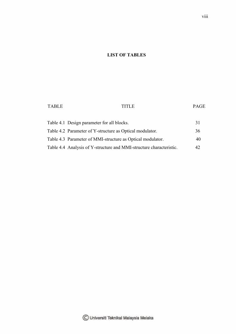
LIST OF TABLES
TABLE TITLE PAGE
Table 4.1 Design parameter for all blocks. 31
Table 4.2 Parameter of Y-structure as Optical modulator. 36
Table 4.3 Parameter of MMI-structure as Optical modulator. 40
Table 4.4 Analysis of Y-structure and MMI-structure characteristic. 42
ix
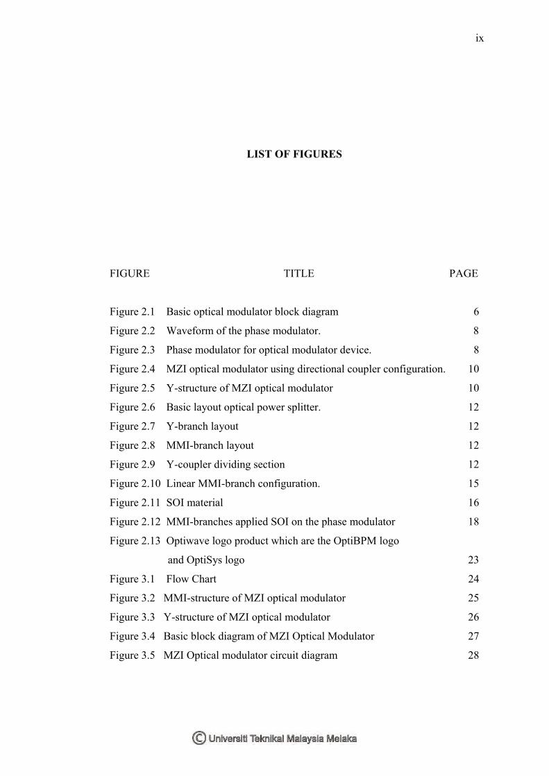
LIST OF FIGURES
FIGURE TITLE PAGE
Figure 2.1 Basic optical modulator block diagram 6
Figure 2.2 Waveform of the phase modulator. 8
Figure 2.3 Phase modulator for optical modulator device. 8
Figure 2.4 MZI optical modulator using directional coupler configuration. 10
Figure 2.5 Y-structure of MZI optical modulator 10
Figure 2.6 Basic layout optical power splitter. 12
Figure 2.7 Y-branch layout 12
Figure 2.8 MMI-branch layout 12
Figure 2.9 Y-coupler dividing section 12
Figure 2.10 Linear MMI-branch configuration. 15
Figure 2.11 SOI material 16
Figure 2.12 MMI-branches applied SOI on the phase modulator 18
Figure 2.13 Optiwave logo product which are the OptiBPM logo
and OptiSys logo 23
Figure 3.1 Flow Chart 24
Figure 3.2 MMI-structure of MZI optical modulator 25
Figure 3.3 Y-structure of MZI optical modulator 26
Figure 3.4 Basic block diagram of MZI Optical Modulator 27
Figure 3.5 MZI Optical modulator circuit diagram 28
x
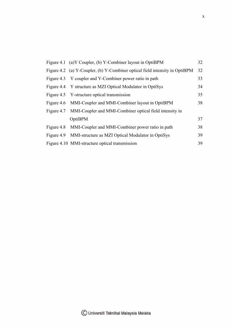
Figure 4.1 (a)Y Coupler, (b) Y-Combiner layout in OptiBPM 32
Figure 4.2 (a) Y-Coupler, (b) Y-Combiner optical field intensity in OptiBPM 32
Figure 4.3 Y coupler and Y-Combiner power ratio in path 33
Figure 4.4 Y structure as MZI Optical Modulator in OptiSys 34
Figure 4.5 Y-structure optical transmission 35
Figure 4.6 MMI-Coupler and MMI-Combiner layout in OptiBPM 38
Figure 4.7 MMI-Coupler and MMI-Combiner optical field intensity in
OptiBPM 37
Figure 4.8 MMI-Coupler and MMI-Combiner power ratio in path 38
Figure 4.9 MMI-structure as MZI Optical Modulator in OptiSys 39
Figure 4.10 MMI-structure optical transmission 39
xi
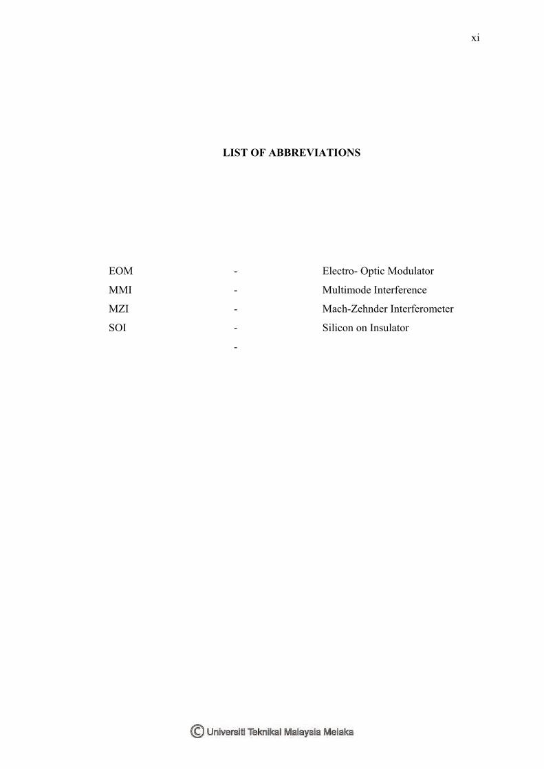
LIST OF ABBREVIATIONS
EOM - Electro- Optic Modulator
MMI - Multimode Interference
MZI - Mach-Zehnder Interferometer
SOI - Silicon on Insulator
-
1
CHAPTER I
1 INTRODUCTION
In this chapter, a complete explanation about the whole project had been
explained. In contains the general idea how this project will be conducted. Related
topics include in this chapter are the Project Introduction, Objectives, Problem
Statement, Scope, Methodology Summary and Report Structure.
2
1.1 Project Introduction
Optical modulator is a device that is able to modulate and vary the optical signal
in a controlled manner. It is an electrical based controlling the output phase and the
output amplitude of the optical signal that passing through the device. This optical
devices been used in photonics devices, optical communication systems and now
widely used in optical electrical integrated circuit (OIEC).
There are many types of optical device such as directional coupler, single
waveguide, microring and Mach-Zehnder (MZ). Implementation of interferometer
technique into the optical modulator created a Mach Zehnder Interferometer (MZI).
MZI is now becoming a new trend in designing an integrated optical devices modulator
due to its simplicity for designing and fabrication[1]. Geometrical structure of MZI
that commonly used are Y-structure and MMI-structure.
MZI modulator four main subsections which are input waveguide, output
waveguide, reference arm and phase modulator arm. Phase modulator will make
optical signal that passes through it been shifted. The structure been used for this phase
modulator is P-I-N structure.
P-I-N structure is a silicon based material through Silicon-On-Insulator (SOI)
technique. The carrier depletion is the method that inject the electrical field on the
phase modulator arm through the P-I-N structure. This doping technique make
changing of refractive index of phase modulator compared to the rest of subsection.
3
1.2 Objectives
The objectives of this project are to:
1. Design and simulate MZI structure using Y-structure and MMI
structure
2. Analyze the performance of MZI optical modulator using both Y-
structure and MM-structure.
3. Propose the best MZI optical modulator.
1.3 Problem Statements
The Y-structure and MMI-structure are widely used as MZI optical modulator.
However, there is no research to compare the performance for both structure can give
better performance. Different structure of MZI can produce different effect on the
optical modulator. Therefore, this project will analyse which structure can give better
performance in MZI modulator.
1.4 Scope
This project focuses to design the MZI structure using Y-coupler and MMI
coupler device. Insertion loss (IL), extinction ratio (ER) and modulation efficiency
(VπLπ) also phase shift (∆ϕ) are among characteristic performance of MZI modulator
4
that will observed. OptiSys and OptiBPM are the mainly software used to design this
project. Dimensions (2D) techniques will be applied to design the coupler device. The
operating wavelength used is 1.55 µm while the refractive index will be used at 3.45.
The phase modulator used P-I-N structure. Meanwhile the material for the devices is
based on SOI.
1.5 Methodology Summary
The methodology of this research is briefly about how the project being
conducted from the designing the coupler device until complete design of the MZI
optical modulator. The project is involving two different kind of software which are
OptiSys and OptiBPM. The OptiSys software been used to design coupler device. The
OptiBPM software been used to design the MZI optical modulator. Further details will
be discussed in Chapter III.
1.6 Report Structure
This report consists of 5 chapters. Chapter I will cover the overview of the
project. It will include the introduction, the objective, problem statements, scope,
methodology review and the report structure.
Chapter II contain the literature review of the project. All information obtained
from the articles and reference books.
Chapter III about the methodology and the project implementation process. This
chapter also describe all parameters used.
Chapter IV describe about the result and discussion based on the simulation.
Observation based on the optical modulator performance has been made
Chapter V conclude the project. This chapter also recommend future work and
step to overcome any limitation.
5
CHAPTER II
2 LITERATURE REVIEW
This chapter will explain more about theoretical analysis and basic principle
project. Through this chapter, all key terms and definition will be explained. All
information had been obtained through journals and reference books. This chapter will
describe about the optical modulator, phase modulator, MZI optical modulator, P-I-N
structure for the phase modulator, performance of the optical modulator and the
OptiBPM and OptiSys software.
6
2.1 Optical Modulator
Optical Modulator is a device that is able to modulate or vary the amplitude
optical signal in a controlled manner. It is divided into two types of modulator which
are the absorptive modulator and the refractive modulator. This project focused on the
refractive modulator on the electro-optic Modulator (EOM). EOM is a device used to
control the phase, polarization or power of optical signal beam with an electrical
control signal.
Optical modulators are used to electrically control the phase or the output
amplitude of the optical wave passes through it. The changes of output waveform is
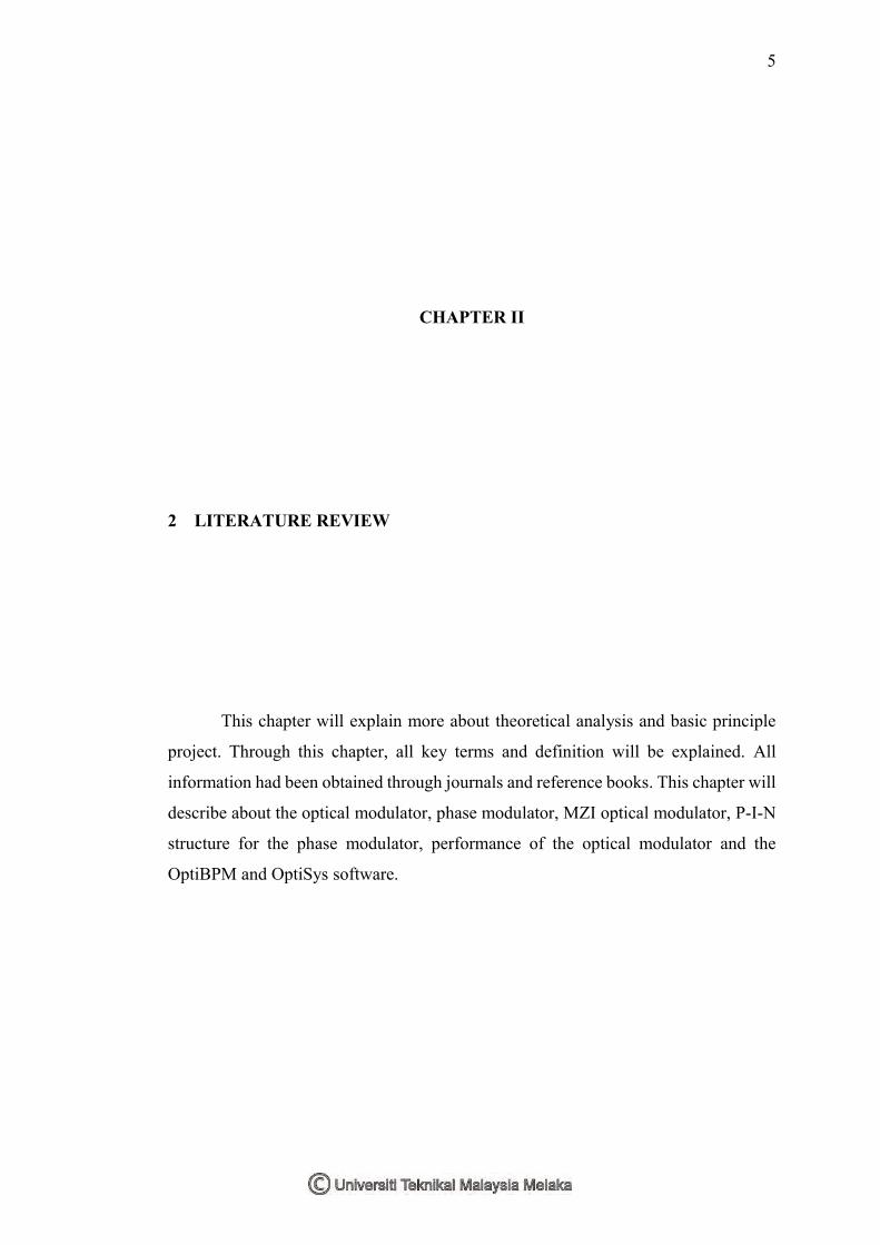
proportional to the applied electric field [2]. Figure 2.1 show basic block diagram of
optical modulator. Elements that highlighted on the optical modulator are laser,
polarizer, electro-optic modulator, analyser and photo detector.
Figure 2.1: Basic optical modulator block diagram
Laser Polarizer Electro-Optic Modulator
Analyzer
Photo-detector
Oscilloscope/ Lock-in AC Power
Supply
7
Laser act as the input optical signal that will pass through the polarizer. At
polarizer it will vary sinusoidal input signal with linear change. The electro-optic
modulator where the phase or amplitude modulator run their function. It will compare
the reference signal with modulated signal. The signal will be transmitted to the
analyzer so that the product of differentiating between the previous signal and current
signal can be monitored. When optical signal is received at the photo detector the
signal will transmit to the oscilloscope lock in where reference signal will be compared
with the incoming signal. When both signal fully matched it means that the overall
signal successfully perform their function and will continuous repeating.
Interference structures that can be implemented as the optical modulator
introduce to the MZI. MZI is an interference structure that can applied on optical
processing signals like switching, add-drop, multiplexing and modulator [3].
2.2 Phase Modulator
Phase modulator is a device locate on the phase modulator arm of MZI optical
modulator. Phase modulator region is where the electrical field applied to it through
the plate electrodes. Then it will change the phase delay of the optical signal [4].
It changes the phase delay of optical signal by applied different density of the
material. Adjusting the value the refractive index can produce different density of
material and it is become a key for semiconductor optical devices. Hence, phase
modulator concern on the refractive index changes and immune from absorption
changes semiconductor waveguide. Effect from that, phase modulator is a device that
the suitable design compared to the absorption modulator in terms of detecting present
changing of refractive index.
8
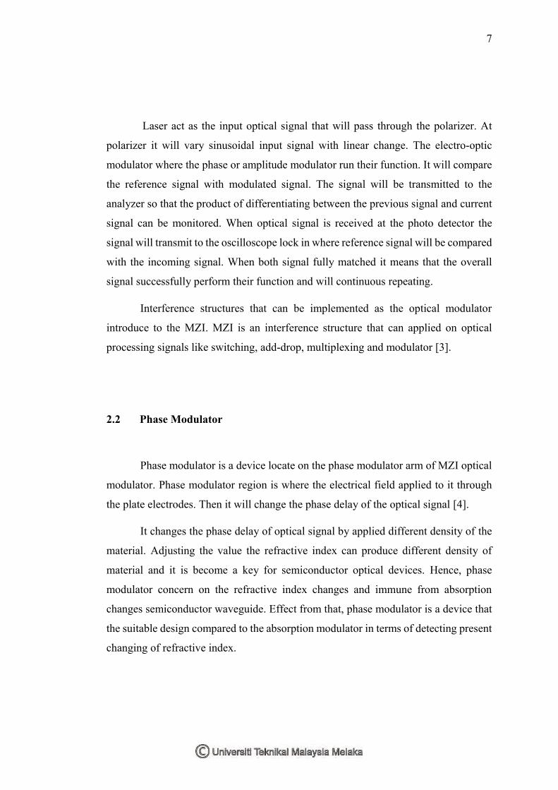
Phase modulator measure and detect some signal by differentiating the
incoming signal with the reference signal. Phase modulation is a technique that
manipulate the changes of phase angle and create new sequence output signal. Figure
2.2 show effect on the signal wave after passed through the phase modulator region.
Figure 2.2: Waveform of the phase modulator.
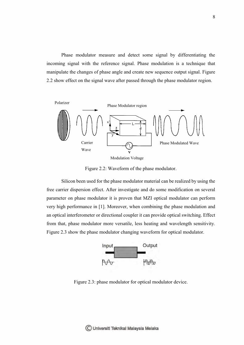
Silicon been used for the phase modulator material can be realized by using the
free carrier dispersion effect. After investigate and do some modification on several
parameter on phase modulator it is proven that MZI optical modulator can perform
very high performance in [1]. Moreover, when combining the phase modulation and
an optical interferometer or directional coupler it can provide optical switching. Effect
from that, phase modulator more versatile, less heating and wavelength sensitivity.
Figure 2.3 show the phase modulator changing waveform for optical modulator.
Figure 2.3: phase modulator for optical modulator device.
Phase Modulator region Polarizer
Modulation Voltage
Phase Modulated Wave Carrier
Wave
9
Research shows that the phase modulator have an ability to inject a free carriers
from the p-n junction configuration to guide light effectively. It can function in both
condition either in forward-bias or reverse bias. When in forward bias it will increase
the efficiency of the phase modulator through the speed characteristics. While in
reversed bias phase modulator can perform in high-speed characteristics with limited
device capacitance. It happen because the free carrier away from the junction and make
electric field produce between the depletion areas. Hence from that, the refractive
index and the phase of propagating signal wave will be changed [2].
Through the carrier injection mode the properties of phase modulator can be
investigate when applied some voltage supply. Phase modulator device can be
integrated in the silicon-on-insulator (SOI) rib waveguide by using P-I-N diode
structure [5]. Performance of phase modulator depending on the value of drive current
(Iπ) is also can be used to find the π phase shift.
2.3 Mach-Zehnder Interferometer (MZI) Modulator
They are few devices for optical modulator but due to the special property of
MZI, it had attracts many researcher about it. Interference happens when two or more
optical waves are present simultaneously in the same area [6].
Interferometer also defined as an optical devices that have ability to splits the
signal into two signal by using the beam splitter and then can to recombine it together
by another beam splitter and detect it through the intensity of their superposition.