Embed Size (px)
Citation preview
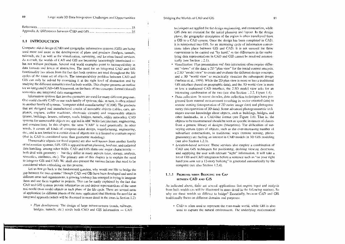
I Bridging the Worlds of CAD and CIS
Peter van Oosterom. jantien Stoter, and Erik jansen
CONTENTS
1.1 Introduction .................................................................................................. 10 1 . I .I Problems when Bridging the Gap between CAD and GIs .............. 11 1.1.2 Overview ........................................................................................... 13
1.2 Case Studies Integrating CAD and GIs ..................................................... 14 1.2.1 Plan Development .............................................................................. 14
I.?. 1.1 Example 1: Hubertus Tunnel .............................................. 14 1.2.1.2 Example 2: Cycle Tunnel, Houten ..................................... 14
..................................................................................... 1.2.2 Visualization I 6 1.2.2.1 Example i : Bridge Amsterdam-Rijnkanaal near CJtrecht ....... I h 1.2.2.2 Example 2: Karma System ................................................. 17
1.2.3 Data Collection .................................................................................. 18 1.2.3.1 Example 1: 3D Cadastral Parcel ....................................... 18 1.2.3.2 Example 2: Point Clouds ................................................. 18
1.2.4 Location-Rased Services .................................................................... 21 1.2.4.1 Example 1: Augmented Reality ......................................... 21 1.2.4.2 Example 2: Disaster Management ..................................... 22
1.2.5 Analyzing the Open Issues when Bridging the Gap between GTS and CAD ...................................................................... 22
1.3 Conversions and Multiple Representations ................................................... 23 1.3.1 Conversions between and within GIs ............................................... 23 1.3.2 Conversions between and within CAD ............................................. 24 1.3.3 Functional and Thematic Semantic Aspects ...................................... 25 1.3.4 Multiview Modeling .......................................................................... 25
1.4 Framework for Bridging the Gap between GTS and CAD .......................... 26 1 . 4.1 Formal Semantics ............................................................................... 27
1.4.1.1 Formal Geometry Semantics in the GJS Domain .............. 19 1.4.1.2 Formal Geometry Semantics in the CAD Domain ............ 31
1.4.2 Integrated Data Management ............................................................. 31 1.5 Conclusions .................................................................................................... 32
.................................................................................................... Acknowledgments 33
10 Large-scale 3D Data Integration: Challenges and Opportunities I
Uridg~ng the Worlds of CAD and GIs 1 1
References ................................................................................................................ 33 Appendix A: Differences betwcen CAD and CIS .............................................. 35
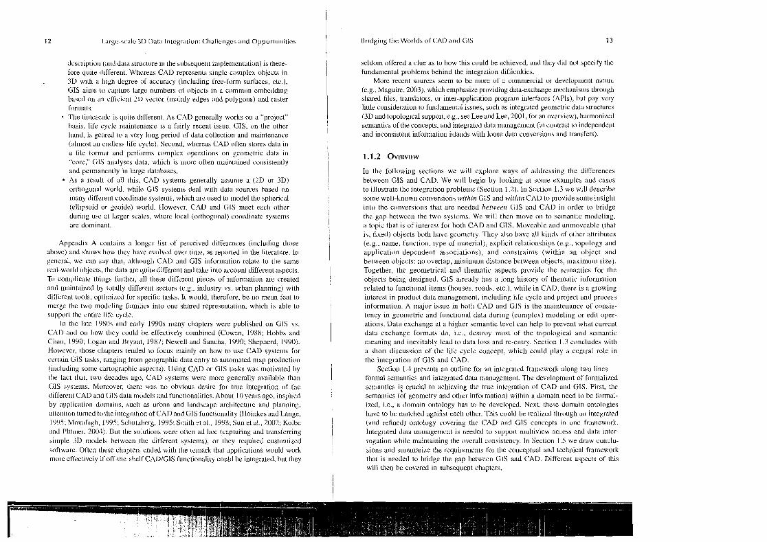
Computer aided design (CAD) and geographic information systems (CIS) are bcing used more and more in the dcvelopmcnt of plans and products (bridges, tunncls, railroads, etc.) as well as for visualization, surveying, and location-bascd services. As a rcsult, the worlds of CAD and CIS are becoming increasingly intertwined - bul not without p r o b l c ~ ~ ~ s . Scveral real-world examples point to incoinpatibility in data fomlata and levcls of abstractiou. The need for an intcgrated CAD and CIS I'uuctionality has arisen from the fact that both systenls are used throughout the life cycles of the same sel of objccts. The interoperability problem between CAD and CIS can only bc solved by examining it at h e right levcl of abstraction and by studying the different se~riantics used in both worlds. This chapter prcsents an outline lor an integrated CAD-CIS framework on the basis of two concepts: formal (shared) semantics and intcgrated data management.
Inl'ormation systems that involve geometry are used for many diflereut purposes. One could clnasify CAD as one auch family of systems; this, in turu, is often rclated to anolhcr family of systems, "computer aided manufacturing" (CAM). The products that are designed and ~nanuhctured consist of moveable objects (tables, cars, air- planes, engines, coffee ~nachines, electronic circuits) and unmoveablc objects (plants, buildings, houses, railways, roads, bridges, tunnels, utility networks). CAD systems l'or unmoveable vbjccts arc applied in AEC fields (architecture, enginecring, and conslruction). In this chapter, the term "CAD" is used ge~~erically. In other words, it covers all kinds of co~nputer-aided design, n~anufacturing, engineering, elc., and is not lin~ilcd to a certain class of objects nor is it limited to a certain aspect (tliat is, CAD is coilsidered inorc than geometric modeling).
Un~novcable objccts (or fixed objects) are also well know11 f r o ~ r ~ another fainily of in~or~ualion aystenls, CIS. GIS is applied in urban planning, land use, and cadastral dala handling, among other lields. CAD and GIS share onc major characteristic - both deal with geometry - but thcy differ in many aspects (size, storage, analysis, sern:u~tics, attributes, etc.). The primary aim of this chapter is to explaii~ the ueed to integrate CIS a11d CAD. Wc shall also present the various factors that need to be considered when embarking on this process.
Let us first go back to Lhc fundamental question, why would one like to bridge the gap between Lhc two systems? Though CAD and GIS have been developed and used in different arcas and organizations, a growing tendency has emerged in trying to integrate them and use Lhcm togelher in projects. This can be easily explaincd by the fact that CAD and G1S systeins provide infunnation on and deliver represenlations of thc same rcd-world (man-made) objects in each phase of the life cycle. There arc several areas of application (or diffcrent phases of the sane application) that illustrate the need for an integrated approach (which will be discussed in more detail in the cases in Section 1.2):
Plan development: The design of large infrastructures (roads, ra~lways, bridgcs, tunnels, etc.) needs both CAD and CIS information - CAD
I techn~ques are applied for the dcsign engineering, and construction, wh~le CIS data are essential for the initial planning and layout. In the design phase, the geographic dcscription of the region is often transferred from a GIS to a CAD system. Once thc deaign has bcen completed in CAD, it is reimported into CIS. So an interesting cycle of information conver- sions takes place between CIS and CAD. It is not ui~usual for these conversions to be carried out "by hand," as the dirferences in the under- lying data representations in CAD and CIS cannot be resolved automat- ically (see Section 1.2.1). Visualization: Plan presentation and data interaction oftell require differ- ent "views" of the data: a 2D "plan view" for the initial context analysis, a 2.5D "~nodcl view" to create and evaluate the differeut design concepts. a ~ ~ d a 3D "world view" to realistically visualize thc subsequent design (Verbrcc ct al., 1999). While the 2D plan view is more or less a traditional CIS intcrfacc (based on geographic data), and the 3D world view is Inore or less a traditional CAD interface, the 2.5D model view asks for an interestiug combination of the two (see also Section I .2.2, Figure 1.4). Dutu cullection: In reccnt decades, data collection techniques have pro-
I I gressed from manual measurement (rcaulting in vector-oriented data) to
remote sensing (inlerpretation of 2D raster image data) and photogram- metry (interpretation of 3D data). Some advanccd photogrammetric tech- niques assume knowledge about objects, such as buildings, bridges, and other landmarks, in a CAD-like format (see Figure 1.6). That is, the objecls to be reconstructed should be seen as spccific instances of classes from a generic library of dcsigns (blueprints). The difliculties of sur- veying certaiu types of objccts, such as the ever-increasing number of subsurface constructions, in traditional ways (remote sensing, photo- granunetry) arc fueling ;In interest in CAD models in 3D CIS modeling (see also Section 1.2.3). Lucution-bu~ed services: These services also employ a combination of CAD and CIS techniques for positioning, deriving viewing directions, and supplying Lhe user with relevant "sight" information. It will take a lot of CIS and CAD integration before a sentence such as "on your right hand you IIOW see a 12-story building" is gcncratcd auto~natically by the computer (see also Section 1.2.4).
I 1.1.1 PROBLEMS WHEN BRIDGING THE GAP 1 BETWEEN CAD AND GIs
As indicated above, lh&e are several applications that reqnire input and analysis from both worlds (as will bc illustrated in more detail in the following section). So why are these worlds so difficult to bridge? Essentially, because CAD and CIS tiad~t~vnally focus on d~fferent doma~ns and purposes:
CAD is often used to represent the man-made world, while CIS is also used to capture the natural environment. Thc underlying mathematical
12 Large-scale 3D Data Integration: Challenges and Opportunities
description (and data structure in the subsequent inlplementation) is there- lore quite different. Whereas CAD represents single complex objects in 3D with a high dcgree of accuracy (including free-form surfaces, etc.), GIS aims lo capture large numbers of objects in a common embedding bascd on an efficient 2D vector (mainly edges and polygons) and raster for~nats. The Li~iicscalc is quite different. As CAD generally works on a "project" hasis, lire cycle maintenance is a fairly recent issue. CIS, on the other hand, is geared to a very long period of data collection and maintenance (almost an endless life cycle). Second, whereas CAD often stores data in a file format and performs complex operations on geometric data in "core," GIS analyses data. which is more often maintained consistently and permanently in large databases. As a result of all this. CAD systems generally assunie a (2D or 3D) orthogonal world, while GIS systenis deal with data sources based on rnany different coordinate systems, which are used to model the spherical (ellipsoid or geoide) world. However, CAD and CIS meet each othcr during usc at larger scales, wlierc local (orthogonal) coordinate systems are dominant.
Appendix A co~~ta ins a longer list of perceived differences (including tl~ose above) and shows how they have evolved over time, as reported in the literature. In general, we can say that, although CAD and GIS information relate to the same real-world objects, the data are quite difl'erent and take into account different aspects. Tci complicate things l'urthcr, all these difl'ercnt pieces of information are created and maintained by totally different sectors (e.g., industry vs. urban planning) with dill'erent tools, optirnizcd for specific tasks. It would, therefore, be no mean feat to merge the two modcling families into one shared represet~tation, which is able to support the entire life cycle.
In the late 1980s aud early 1990s many chapters were published on CIS vs. CAD and on how they could be effectively combined (Cowen, 1988; Hobbs and Chan, 1990; Logan and Bryant, 1987; Newel1 and Sancha, 1990; Shepherd, 1990). However. those chapters tended lo focus mainly on how to use CAD systems [or certair~ GIS tasks, ranging fro171 geographic data entry to automated map production (including somc cartographic aspects). Using CAD or CIS tasks was motivated by the fact that, two decades ago, CAD systems were more generally available than CIS systems. Moreover, there was no obvious desirc for true integration of thc differen1 CAD and CIS dala models and functionalities. About 10 years ago, inspired by applicatio~~ domai~ls, such as urban and landscape architecture and planning, attention turned to thc integration of CAD and GIS fu~lctionalily (fioinkes and Lange, 1995: Movafagh, 1995; Scliutzberg, 1995; Smith et al., 1998; Sun et al., 2002; Kolbc and I'M~ner, 2003). But the solulions were often ad hoc (capluring and ~ransfcrring simple 3D nlodels between the different systems), or they required custon~ized softwarc. Often tl~ese chapters ended with Lhe remark that applications would work rnore effectively if off-the-shelf CADICIS functionality could be integrated, but they
Bridging the Worlds of CAD and CIS 13
seldorn offered a clue as Lo how this could be achieved, and thcy did not specify the fundan~e~ital problems behind the integration difficulties.
More recent sources seem to be more of a co~nniercial or development nature (e.g., Maguire, 2003), which emphasize providing data-exchange mechanisms through shared files, translators, or inter-application program interfaces (APls), but pay very little consideration to fundamental issues, such as integrated geometric data structures (3D and topological support, e.g., see Lee and Lee, 2001, for an overview), harmonized semantics of the concepts, and integrated data management (in contrast to independent and inconsistent informatio~~ islands with loose data conversions and transfers).
In the following sections we will explore ways of addressing the differences between CIS and CAD. We will begin by looking at some examples and cascs to illustrate the integration problems (Section 1.2). In Scctiol~ 1.3 we will describe solrle well-known conversions within G1S and within CAD to provide some insigl~t into the conversions that are needed between CIS and CAD in order to bridge the gap between the two systcms. We will then move on to semantic modeling, a topic that is of interest for both CAD and GIS. Moveable and unmoveable (that is, fixed) objects both have geometry. They also have all kinds ol'otlicr attributes (e.g., name, function, type of material), explicit relationships (e.g., topology a ~ ~ d application-dependent associations), and constraints (within an object and between objects: no overlap, minimum distance between objects, maximum size). Together, the geometrical and thematic aspects provide the semantics for the objects being designed. GIS already has a long history of thematic i~iformation related to functional items (houses, roads, etc.), while in CAD, there is a growing interest in product data management, including life cycle and project and process information. A major issue in both CAD and CIS is the ~ n a i n t e ~ ~ a n c e of consis- tency in geometric and functional dala during (complex) modeling or edil oper- ations. Data exchange at a higher semantic level can help to prevent what current data exchange formats do, i.e., destroy most of the topological and sc~nantic meaning and inevitably lead to data loss and re-entry. Section 1.3 concludes with a short discussion of the life cycle concept, which could play a central role in the integration of GIS and CAD.
Section 1.3 presents an outline for an integrated framework along two lines -- formal semantics and integrated data management. The developme~~t of formalized semantics is crucial to achieving the true integration of CAD and GIS. First, the semantics (Af geometry and other information) within a domain need to be formal- ized, i.e., a domain ontology has to be developed. Next, these domain ontologies havc to be matched agaiAst each othcr. This could be realized through all integrated (and refined) ontology covering the CAD and GIS concepts in one framework. Integrated data management is needed to support n~ultiview access and data inter- rogation while maintaining the overall consistency. In Section 1.5 we draw conclu- sions and sunlmarize the requirements for the conceptual and tech~~ical framework that is needed to bridge the gap between CIS and CAD. Different aspects of this will then be covered in subsequent chapters.
14 Large-scale 3D Data Integration: Challenges and Opportunities 1 Bridging the Worlds of CAD and CIS
1.2 CASE STUDIES INTEGRATING CAD A N D GIs I i I
In this section we present a number of case studies relating to the application areas rrlentioned irr the introduction; these include plan development, (3D) visualization, (3D) data collection, and location-based services. Sorr~e of the cases will illustrate o p c ~ issues (problems) with respect to the integration of CAD arid CIS, while olhcr I cases may also show initial parts of the solution (of~eri by making agreements and adapting the dataflow for the anticipated integration of CAD and GlS). After studying these cases, we will conclude with an analysis and summary of the prc~hlems we encountered when trying lo bridge the gap between CAD and CIS.
1.2.1 PLAN DEVELOPMENT
1.2.1.1 Example 1: Hubertus Tunnel I
The first example in the planning process is taken from 3D cadastre research (i.e.. I
actual property rrgislration). Property 1-cgistration, including the geclgrapliic arid thematic information, is often implemented with a GIs, usually with an underlying geo-DBMS for data managelnent. Information in 3D on physical objects is required when registering the properly of constructiorls above and below the surface. 'L'hc question is, how can this 3D description be obtained?
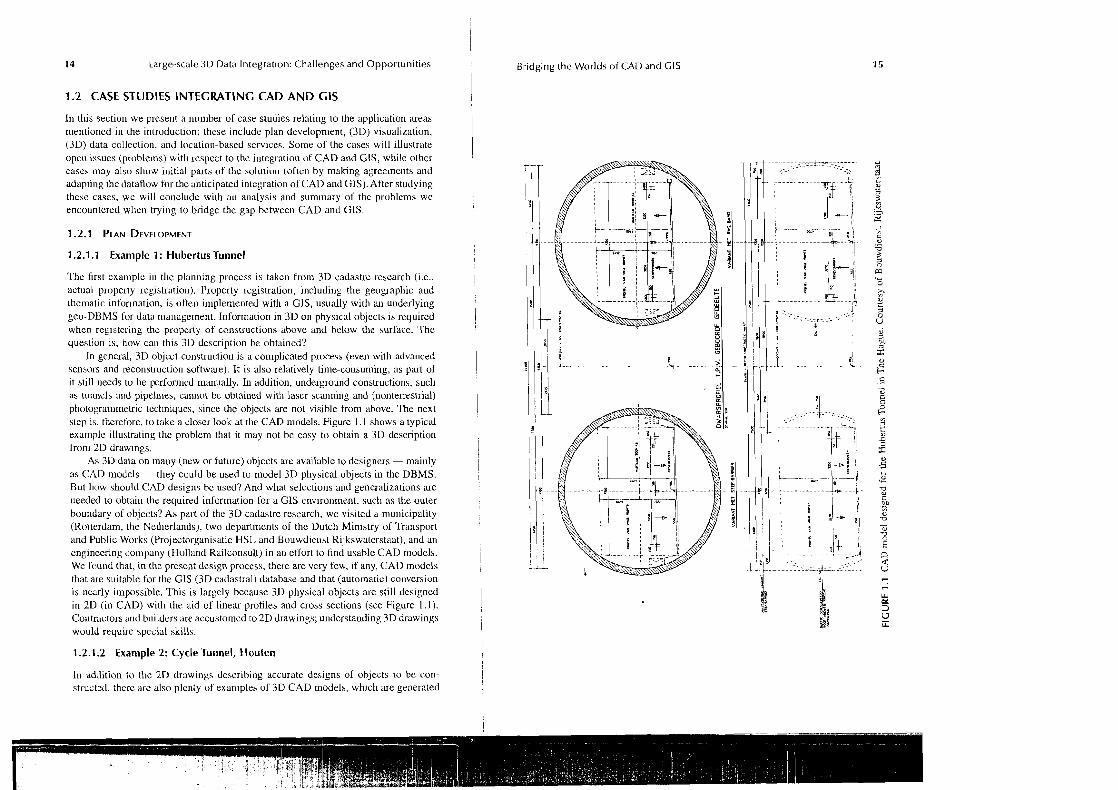
In general, 3D object construclion is a complicated process (even with advanced sensors and reconstruction software). It is also relatively time-consuming, as p a t of it still needs to be performed manually. In addition, underground constructions, sucll as turrricls iuld pipelines, cannot be obtained with lascr scanning ,md (nonterrestrial) photogrammetric tcchniqucs, since the objects are not visible from above. The next step is, therefore, to take a closer look at the CAD models. Figure 1.1 shows a typical example illustrating the problem that it may not be easy to obtain a 3D description from 2D drawmgs.
As 3 0 data on many (new or future) objects are avaikable to designers -mainly as CAD models -they could be used to model 3D physical objects in the DBMS. Bul how should CAD designs bc used? And what seleclioris and generalizations are rreeded to obtair~ the required information lor a GIS cnvironmznt, such as the outer boundary of objects? As part of the 3D cadastre research, we visited a municipality (liotterdam, the Netherlands): two departments of the Dutch Ministry of Transport and Public Works (Projectorganisatie HSL and Bouwdienst Kijkswaterstaat), and an cngincering company (Holland Railconsult) in an effort to find usable CAD models. We found that, in the present design process, there are very few, if any, CAD ~nodcls that are suitable for the CIS (3D cadastral) database and that (automatic) conversion is nearly in~possible. This is largely because 3D physical objects are still designed in 2D (in CAD) with the aid of linear profiles and cross sections (see Figure 1.1).
i Co~rtractors and builders are accustomed to 2D drawings; understanding 3D drawings would require spccial skills. ! 1.2.1.2 Example 2: Cycle Tunnel, Houten
i In addition to the 2D tlrawings describing accurate designs of objects to be con- j I strutted, therc are also plenty of exan~ples of 3D CAD models, which are generated
16 Large-scale 3D Data Integration: Challenges and Opportunities ! Bridging the Worlds of CAD and CIS 17
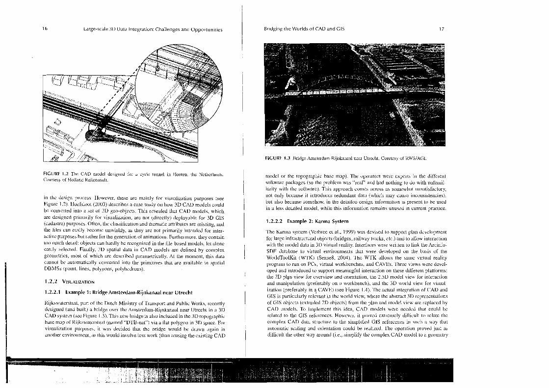
FIGURE 1.2 Thc CAD ~rlodel dcs~gned for a cycle tunnel in Ilouten, the Netherlands. Courtesy of Uolland Railconsult.
in the design process. However, these are mainly for visualization purposes (see Figurc 1.2). Hocfsloot (2003) describes a case study OII how 3D CAD models could be converted into a set of 3D geo-objects. This revealed that CAD n~odels, which are designed primarily for visualization, are not (directly) deployable for 3D GIS (cadastre) purposes. Often, the classification and thematic attributes are missing, and the files can easily becon~c unwieldy, as they arc not primarily intcnded for inter- active purposea but rather for the generation of animations. Furthermore, they contain too much detail: objects can hardly be rccognized in the lile-based models, let alone easily selected. Finally, 3D spatial data in CAD models are defined by complex geometries, most of which are described parametrically. At the ~nolncnt, this data cannot bc automatically converted into the primitives that are available in spatial DBMSs (point, lines, polygons, polyhedrons).
1.2.2.1 Example 1: Bridge Amsterdam-Rijnkanaal near Utrecht
Kijkswatcrstaat, part of the Dutch Ministry of Transport and Public Works, recently designed (and built) a bridge over thc Amsterdam-Rijnkanaal near Utrecht in a 3D CAD syhtcrn (see Figure 1.3). This new bridge is also included in the 3D topographic base map ol' Kijkswatcrstaat (named "DTB-nat") via a Hat polygon in 3D space. For visualizatioll purposes, it was decided that the bridge would be drawn again in ar~otl~er cnvirollment, as this would involve lcss work (than reusing the existing CAD
FIGURE 1.3 Bridge A I I I S I ~ I ~ ~ I I I - R i j ~ ~ k a r l a a l near Utr-ecl~l. Courtesy at' l<WSIAGI
model or the topographic base map). The operators were cxpcrts in the difl'erent softwarc packages (so the problem was "real" and had nolhing to do with unfamil- iarity with the software). This approach comes across as so~newhat unsatisfactory, not only bccause it introduces redundant data (wl~icli nlay causc incoi~siste~~cies), but also because somehow, in the detailed design illformation is present to be used in a less detailed model, while this inlormation remains unused in currerlt practice.
1.2.2.2 Example 2: Karma System
The Karl~la system (Vcrbrce et al., 1999) was devised to support plan devclopmerlt for large infrastructural objects (bridges, railway tracks, etc.) and to allow interaction with the nod el data in 3 0 virtual reality. Interfaces were written to link the Arcil~fo- SDE database to virtual ellvironments that were developed on the basis of the WorldToolKit (WTK) (Sense8, 2004). Thc W'TK allows the salnc virtual reality program to run on PCs, virtual workbenches, and CAVES. Threc views were devel- oped and ir~troduced to support meaningful interaction on these dirfercnt platforms: the 2D plyn view for overview and orientation, the 2.5D model view for interaction and ~nanipulation (preferably on a workbench), and thc 3D world view for visual- ization (preferably in ? CAVE) (see Figure 1.4). The actual integration of CAD and GIS is particularly relevant in the world view, where the abstract 3D representations of GIS objects (extruded 2D objects) from the p1a11 and model view are replaced by CAD 111odels. To implement this idea, CAD models were nccdcd that could be related to the GIS references. Howcvcr, it proved extremely dil'licult to relate the complex CAD data structure to the simplified GIS rei'ercnccs in such a way that automatic scaling and orientation could be realized. The operation proved just as diSIicult the other way around (i.e., si~nplify thc coinplex CAD model to a gconictry
Large-scale 3D Data Integration: Challenges and Opportunilies Bridging the Worlds of CAD and GI5
FIGURE 1.4 (See color insert alter page 86). 21) plan view, 2.51) model view, and 3D world view in Karma.
that could be linked to the "ground plan" of the object in the GIs databasej. So, the Karma system did indeed succeed, up to a certain levcl, to intcgrate CAD and GTS objects and their i'unctionality. However, as described abovc, this was not easily achieved, and i t involved much nonautornated "hand work," taking too much time.
1.2.3 DATA COLLECTION
1.2.3.1 Example 1: 3D Cadastral Parcel
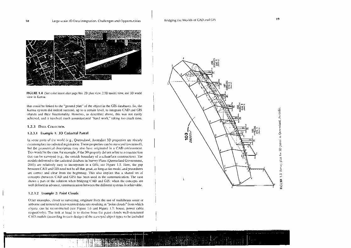
In some parts of the world (r.g., Queensland, Australia) 3D properties are already comn~onplacc iu cadastral registration. These properties can be surveyed (measured), but the gcornctrical description may also have originated in a CAD erivirontnent. This would be the case, for example, if Lhe 3D property did not relate to a construclion that can be surveyed (r.g., thc outsidc boundary of a subsurface construction). The models delivered to [lie cadaslral databasc in Survey Plans (Queensland Governrnent, 2003) arc relatively easy to incoiporate in a GIs; sce Figure 1.5. Here. the gap belween CAD and GIS need not be all that great, as long as the model and procedures arc corrcct and clellr from the beginning. 'This also implies that a shared set of concepts (belwceli CAD and GIs) has been used in the communicatio~~. The case shows a par1 of the bolution when bridging CAD and GIs: when the concepts are well defined in advance, communication betwcen the diffe~ent systems is achievable.
1.2.3.2 Example 2: Point Clouds
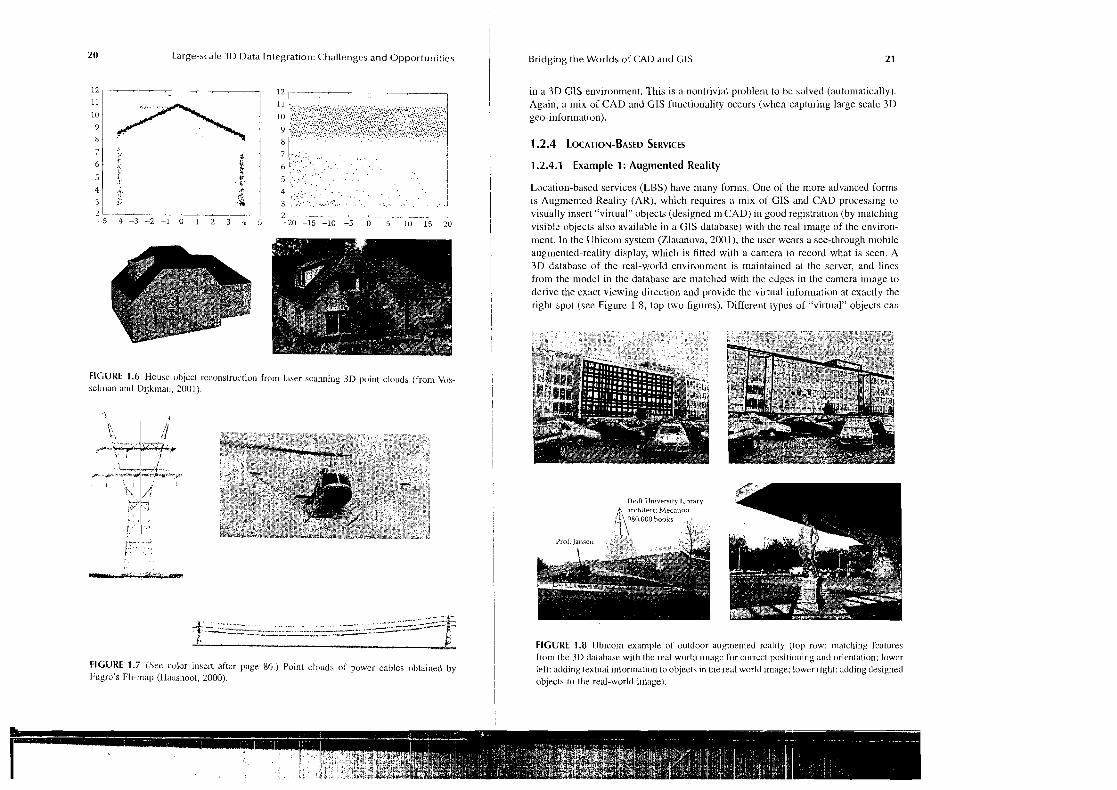
Other examples, closer to surveying, originate from the use of rnultibeam sonar or nirbor~ic and terrestrial lascr-scanned data sets resulting in "point clouds" from which objects can bc reconstructed (sce Figure 1.6 and Figure 1.7: house, power cable respectively). The task at hand is to derive from the point clouds well-slructured CAD models (according to [heir design) of lhc surveyed object types to be included
20 Large-scale 3D Data Inlegration: Challenges and Opportunities 1 Bridging the Worlds of CAD and CIS 2 1
in a 3D GlS environment. This 1s a nontrivial problem to bc aolved (automatically). Again, a mix of CAD and GIs functionality occurs (wl~en capturir~g large scale 3D geo-information).
1.2.4.1 Example 1: Augmented Reality
Location-bascd services (LBS) have many forms. One of the more advanced forms is Augmented Reality (AR), which requires a mix of CIS and CAD processing to visually insert "virtual" objects (designed in CAD) in good registration (by ~nalching visible objects also available in a CIS database) with the real image of the environ- ment. In the Ubicorn system (Llatanova, 2001), the user wears a see-through mobile augmented-reality display, which is fitted with a camera to record what is seen. A 3D database of the real-worId environment is maintained at thc server, and lincs horn the ~iiodcl in the database are matched with the cdges in the camera image lo derive the exact viewing direction and provide the virtual information at exactly the right spot (see Figure 1.8, top two figures). Differellt types of "virtual" objects can
FIGURE 1.G House objcct r-cconslruction from laser scanning 3D point clouds (from Vos- sclman and Dijkrna~~. 2001).
FIGURE 1.7 (Sce color inscrt after page 86.) Point clouds of power cables obtained by Fugru's Iyli-map (Haasnoot, 2000).
FIGURE 1.8 Ubicorn example of outdoor augmented rc:rlily (top row: matching I'catul-es from the 3D database wilh the real world ilr~agc for corrccl posilioriing and orientation; lowcr left: adding lextual information to objecls in the real world image; lowrr righ~: adding designed objecls to the real-world image).
22 Large-scale 3D Data Integration: Challenges and Opportunities ~ Bridging the Worlds of CAD and CIS 2 3
be added to the real-world image: I. Planned and designed objects not yet realized in the real world, 2. Real, but invisible objects could be displayed in the right perspective (e.g., subsurface objects), and 3. Textual information can be added in "clouds" attached to real-world objects describing certain properties. Again, these cases show the integrated use of CAD and G1S functionality.
1.2.4.2 Example 2: Disaster Management
Another example is the (geo-) ICT support for policc, ambulances, and firefighters in emergencies or crisis situations; the emergency scrvices might want to use both outdoor and indoor information in an integrated manner (via the interfaces of (heir mobile equipn~ent). At present, interior building designs from CAD systems and geographic information (from GIS) have to be combined in one environment. Again, this case shows the need to offer integrated GIs and CAD functionality within one application or user environment.
1.2.5 ANALYZING THE OPEN ISSUES WHEN BRIDGING THE CAP BETWEEN CIS AND CAD
As several of the ahove exan~ples illustrate, large-scale 3D geo-information is a subject of great interest for CAD and GIS users alike. This is also reflected in the G1S-extendcd CAD software packages of the market leaders such as Autodesk's AutoCADlmap, and Bentley's Microstaton Geographics (Bentley, 2004). Recently, CAD designers have been confronted with more and more requests for Reo- information (i.c., the geometry of identifiable objects with a fixed location with respect to the earth) lo which other information can be linked. This data can serve many purposes, e.g., spatial analysis or the updating of existing geographic data sets with planued (designed) objects. Much progress has been made in 2D in the past few years; after all, cadastral parcels can now be designed in CAD systems (with svmc kind of geographic extension) and maintained in a DBMS. These local, designed environments are now part of the complete world for which coordinates are needed. As the same information is constantly being reused and updated, a system is needed whcreby the integrity and consistency of the spatial, temporal, and thematic data is maintained.
However, data sharing between CAD and GIS appears to be difficult in practice. It is not unusual for two departments (one working with CAD and another with GlS softwae) in one organization, such as a province or state, to not communicate because they cannot exchange data. Everybody who has tried to import CAD data into GIS software has experienced this in one way or another, e.g., lack of object definitions in the CAD models, different scale rcpresentations. transformation of the local (CAD) coordinates into a reference system for both the horizontal and vertical coordinates, parametric shapes that cannot be converted into GIS objects, different levels of detail that require generalization, etc. OLlen, there is also a conceptwal or seinantic dicference between the concepts in a design (CAD) environment and the concepts in the observed and ~neasurcd gco-information (as in GIS). These conceptual frameworks (ontologies)
1 have to be made explicit and compared and related to each other before things can I
i improve. In 3D, spanning a bridge between CAD and GIs is even more of a challenge.
I CAD software provides all kinds of primitives to create geometric (and their visual attributes) models close to reality; however these primitives are not supported in
1 CIS. I-low can CAD primitives (e.g., parametric primitives) bc used in an Open
I Geospatial- (or I S 0 TC21 I - ) compliant environment or the other way round'! How can Open Geospatial primitives be used in coinbination with CAD lunctionalities I
! (textures, shading, etc.) to represent a model close to reality'! In 3D, CAD designers may become major providers (holding the set ol' tools to edit and update) of Iarge-
I scale geo-data for use in GIS once a fundamental bridge between CAD and GIS has
1 been established. It should be noted, at this point, that up-to-date, large-scale geo- information is being used more and more as the source of derived mediunl- a~ld small-
I scale geo-information after (dynamic or on-the-Hy) generalization. ~ Not surprisingly, if we convert data from GlS to CAD and vice vcrsa, enorlnous 1 mismatches will arise in the elementary data representations and auto~llatically lead
to a loss of (implicitly encoded) semantic meaning or information. Maiutaining the I
I integrity and functional meaning of the data is, therefore, a crucial issue in "bridging"
! the two domains. Much research is needed to examine in detail the interoperability problem between GIS and CAD.
I 1.3 CONVERSIONS AND MULTIPLE
REPRESENTATIONS
To get a "feeling" for conversions between CAD and GIs, it is worthwhile to take a look at some conversions within a domain. I~nportant lessons can be learned up front from these examples, which can later be useful when widening the scope again (and covering both GIS and CAD representations). We will start with solne conver- sions (including geometly and thematic information) from thc G1S donlain (Sec- tion 1.3.1) and then move on to the CAD domain (Section 1.3.2). The i~r~portant role of semantics during the conversions and several aspects of semantics (alached to the geometric objects) are discussed in Section 1.3.3. Often, the different rcpre- sentations of the same object arc due to the specific application environment. lnstcad of considering the different representations as hiffercnt objects, it is better to consider the111 as the sanie object to which different views are assocbated (depending on the context). Section 1.3.4 will show that these viewa arc closely related to the phase of its life cycle the object is in (design, conatruct, survey, ~nainlain, ctc.).
Examples from the GIS donlain include the following:
From large-scale (detailed) to small-scale (overview): This proccas is called ,qetlerulizutiot~ (not to be confused with spccializalion and generaikation within the object class hierarchy). It is essential to understand the meaning
24 Large-scale 3D Data Integration: Challenges and Opportunities
ol' the diSScrent objccls and h c purpose or ask of thc person using the reprcscntaliou or map. Fro111 digital laudscape riiodcl (dala structure or database) to digital car- tog~.aphic modcl (display on screen, paper, e t ~ . ) : This process is called visuulizu/ion. Again. the sel~~antics are important in order to choose the right graphic prinlitivea or symbols (for the diCCerent object classes) and the right graphic parameters (color, width, texlure) to represent the value of rclevant attributes. A thorough u~~derstanding of sc~nantics is required lo achieve schernu inregrutiott (crcaling models with "the best of both worlds" in one uniform envirurlmcnt) and schernu rntrp~~ing (converting models, objects, or descriptions from one world irito the concepts used in the other world) on the basis of geographic data from heterogeneous sources covering the same legion.
1.3 .2 CONVERSIONS BETWEEN AND WITHIN C A D
Exa~nplcs from the CAI) domain include the followmg:
Levels of detail: 111 ordcr to maintain interactivity and real-lime display, a complex CAI) model ol'ten has to be simplified in the polygon count, but not at the expense of visual quality. In a flight sin~ulator, the resolution of Lhe terrain niodel is adaptively improved and simplified according to the posilion of Lhe aircraft above the terraill. Here we skive for a coutin- uum between thc local detail and the overview. Anothcr technique known as "occlusion culling" reduces the polygon count when rendering large urban er~viron~~lcnts from street level, where large parts of the town will riot be visible anyhow. Using the facades of the street as "clipping planes,"
- -
and merging these complicated facades into simplified "virtual occluders" will speed up the visualization process with ordcrs of magnitude (Wonka and Schn~alsteig, 1999.) Mesliinfi: Although the same basic geometry is used for several functional ar~alyses (e.g., calculations of strength and stifliicss), Llie exact for111 can din'er from application to applicalion. For instance, (inite element stress analysis needs volumetric meshing. Ideally, the mesh resolution should be adapted to the gradient of Lhe local stress in order to avoid unnecessary co~nputations in regions where nolhing is happening and to achieve high accuracy in regions wit11 large stress concentrations. A dil'ferent mesh topology might ligure in other finite-element sin~ulations such as "mould flow," bccausc here we want to concentrate on the thin and distant parts lhat the How might have difficulty reaching. Feuture rrludeling trnd conversiorts (Uidarra and Bronsvoort, 2000; Urousvoort and Noorl, 2U04): The notion of "feature" has been defined lo elicotlc thcmatic information in combination with geometry. A leaturc is a shape elemcnt with some predefined functional meaning. For instance, a cylindrical hole might be defined as a through hole or a blind
Bridging the Worlds of CAD and CIS
hole depending on the topology (open or closed at Lhe bottom) and the manufacturing process. Again, the same part of the geomctry might "feature" in different feature reprcscntations, depending on whether we want to use a picce of the geometry (e.g., a surfacc plane) as a refercncc for the surlace smoothness properties, or as a reftrence plane in an assembly, or as a fixing plane in a machining operation.
As we can see from these examples, model co~iversions are scldorn based on pure geo~rietric "~anslations." I11 most cases, some funclional knowledge ("sernuntics") about Ihc geometry is also applied to interpret the functional meaning and to maintain consistency (e.g., Lhe geometry is closed) and validity (il still perfc~rnms its intended function). The different aspects of "semantics" can bc encoded in the following ways:
Paramehization: Some of the geo~netry variables are used as defining parameters that disccrn the product in diirercnt classes (discrete param- ctcrs) or in conti~iuous shape ranges Procedural definition: Algorithmic or conlputational shape definition to define repetition or a certain randomness Topology: Relations between geonletric elernents to encode "connective- ness" and "uniqueness," i.e., elerne~its do not overlap, and the boundary is complete and closcd Constraints: As in the case of topology relations but with a general numeric or computational character to def ne certain geometric or topo- logical properties
A powerlul modeler w i h at least some "solving" capabilities is needed to maintain the functional relations. For instance, if a bridge is lowered, this may inhibit a pass-through l'unction for trucks. Ideally, thc system would chcck and maintain this type of functional constraint. It oftell takes a complicated proccss to spccify Ll~e constraint and dcterrnine the degrees of freedom, which are left Tor adjustment. All of these observations indicate that simple conversions do not exisl and, hence, that si~uple schemata based on "geouietry alone" will not work.
The sellrantic content of modcls can also be organized by arl-anging the data accord- ing to aspects of deskn and manufacturing or life cycle stages. There arc several ways of classifying this life cycle. Onc approach is described below:
2 6 Large-scale 3D Data Inlegration: Challenges and Opportunities
It should bc noted that this life cycle is ongoing, because objects are added, dclcted, and redesigned in 11cw cycles (in the spatial contcxt), which again follow the same phases. DiKercnt sectors are inlerested in different aspects of the same real-world objects and use diffcreut tools lo create and work with the information (~nodels) associated with thcm. Each sector or organiration chooses the tools that are optimized for the lask at hand. Also, the (data) model and the data storage (DBMS, lilcs, formats) inighl be completely different.
The life cycle should be given a central place in the integration, as it comprises the diffcrent design, manufacturing, and analysis aspects. To address the life cyclc concept in GlS and CAD at a fundamental level, the data should be explicitly storcd only once at a basic level, and a "view specific data" stmcture should support and allow data analysis and n~anipula~ion from a variety or perspectives without disturb- ing the underlying consistency.
Gel~erally speaking, conversion beiwccn ditlerent representations is not simple - not even within the GIs and CAD packages, let alone between them. The convcrsions cannot be fully aulomated within the current state-of-the-art CIS and CAD software and tcclinology, and human intervention is slill required to obtain acceptable results. Hence, bolh versions of a nod el (original and post-conversion) are often kept and storcd explicitly. This could be called a ~nultiple-represeneation solution. Care must bc take11 lo ~riaiutain consislency during updates. However, with lechnological progress (and the trend loward more lbrmal semantics), it should be possible to have fully aulomatic convcrsions (perhaps also by lowering the requirements for the difrerent vicws). It should be possible in the future to have only one (integrated) source of thc model and to compute (updatable) vicws.
1.4 FRAMEWORK FOR BRIDGING THE GAP BETWEEN CIS AND CAD
T11e open isaucs whcn integrating CIS and CAD representations and functionality (sec Scction 1.2.5), illustrated in the case studies (see Sections 1.2.1-1.2.4), can be addressed by applyi~~g the experience and knowledge gained from the conversions that are already available within GlS and CAD (see Section 1.3). These conversions use both semanlics and gcomctry to arrivc at different representations of the same real-world ol>jecl. Whal is needed in order to bridge thc gap between CIS and CAD is a frarncwork that covers both the geometry and the semantics. This section will begin wilh a prclin~inary rc~uark on model class and instance level and then consider the conditions for such a fnlmcwork, namely: formal semantics (see Section 1.4.1) and in~cgratcd data managerrlent (scc Secliou 1.4.2).
Whcn we refer lo inodcling, we can distinguish between ~ w o levels:
klodcl class levcl: Define a blueprint (structure) for the vbjccts later on, dcscr~bc Lhcir atlributcs (spatial and thematic), relationships, etc. Essentially, this is tllc object class model (derived from object-oriented approaches to rnodcling and design) with evcrytliing at object class level (including the class i~lllc~ilancc hierarchy and aggregatio~dco~r~posite relationships).
Bridging the Worlds of CAD and GI5 2 7
Model instance level: Create an actual abstraction of (some part ol) the (planned or designed) real world, i.e., create instances of the object classcs defined above: spccify actual geometries and thematic attributes, crcate ~ela~ionships, and satisfy specified conslraints.
Design tools are availablc to creatc nlodels at class level. The Unified Modeling Language (OMG. 2002) is used to create models in all kinds of disciplines. Highly appropriate in this context are the class diagrams. These are not only used in the development of information systems, but also to capture (formal) semantics in specific domains (e.g., the semantic web and slruclured diclionaries).
I1 can be concluded from the above discussion that an imporlant key to bridging CAD and CIS is to capture the semantics in the different models. However, implicil knowledge or tidy pieccs of natural text and tablcs are not sufficient for this purpose. A more formal approach is required, as developed in disciplines such as knowledge cngineering, ontologies, and objcct-oriented modeling. On lhe basis of this lorma1 semantic approach, it becomes possible to decide whether dillerelit domain nlodcls (or cvcn models within one domain) are or can be harmonized. Mcanti~ne, morc meaningful handling of spatial inforrnalion (by machiocs) will become all thc more important and make the formal approach even morc necessary. In the lasl decade, significant technological progress was made in knowledge engineering (via the develop~nents from UML, ontology, semantic web, OWL), which enables knowl- edge to be furthcr formali~cd in a practical way.
At presenl, most spatial (both CAD and GIs) information is used rnore or less directly by humans; in the future large parts of thc information will also be processed (iirst) by machines (before recommencing com~nunication with hurnans). Whcrcas humans are capable of interpreling diflerent concepts by using implicit contcxt information (which domain is involved, who supplied or produced the information, etc.), Lhis knowledge will have lo be made explicitly availablc Sor a machine. A large part of the l'orrnal slructural knowledge about the concepts (objecls b e i ~ ~ g modeled) is captured in the relationships that one object has with othcr types of objccts (specialization/generalization, part/whole, association), characteristics (attributes), and opcrations (methods, fullctions) bclonging lo the object class. The principles of object-oricnled nodel ling are also discernible in this knowledge-el~ginecring approach,
To m\ke the idea of ~nachine handling of geo-inlormation a little less abstracl, one could think of automaling the conversions as described in Scction 1.3. Other cxamples are automatit inlcrpretation of sensor inSc)rnlation (e.g., acrial pholograpliy. remote-sensing, or laser-scanning data sets) or recognizing and classifying objects or cxccuting several (spatial) analyses in the conlext of a "dccision support systcnl." What all these tasks have in common is that, without Lhc "domain knowlcdgc," a ~nachinc could never execute thcm in an adequate manncr. Interestingly, the wish for formalization of knowledge also occurs in many other disciplines and domains. Attempts arc bcing made LO formalize knowlcdgc will~in specific domains (e.g., ship
28 Large-scale 3D Data Integrat~on: Challenges and Opportunities
construction and ~iiedical disciplines) or even to compile complete collections of common and gcneral concepts (dictionaries). Most of the time, these attempts are launched for exactly the same reason (to make a machine do certain tasks in a meaningful manner). For example, efforts are underway in the context of the "seman- tic web" to provide more meaningful search operation by developing formal frame- works of' coucepts ("or~tologies" and making them operational). The UML class diagrams are l'requcnlly used for this purpose (OMG, 2002). Additional ~nelhods aud tools are also used to, for example, map equivalent concepts in (different) frameworks or "rewrite" infornlation from one set of well-defined cvnccpts to the terminology of another (a geo-information example would be translating from the GBKN (Large Scale Map of the Netherlands) to the TOPIONL (Top10 vector data set of the Ncthcrlands)).
Thougl~ UML class diagrams more or less constitute the "default" approach when crcating rormal knowledge i'ramcworks, the graphic diagram has limited semantic accuracy. A nongraphic language is provided withill UML for the further modeling of semantics (knowledge frameworks) with the aid of the Object Constraint Language (OCL, see OMG, 7002; OMG, 2003). This can be used to specify the criteria for a valid ri~odel (constraints), such as invariants for classes i111d pre- and post-conditions for operations. The advantage of using UML is that, as in the case of UML class diagrams, gcneric tools are available to support OCL (i.e., not CAD- or GLS-specific). Tlie context of an invariant is specified by the relevant class; e.g., "parcel" if tlie constraint were that "the area oi' a parcel is at least 5 m2." It is also possiblc within a constraint to use the association between two classes (e.g., "parcel" must have a1 least one owner, which is an association with the class "person"). The following are two ex;~mplcs in UML syntax (keywords in bold print):
context P a r c e l inv r n i n i n ~ a l A r e a :
context Parcel inv h a s o w n e r :
s e l f . O w n e r -> notEmpty ( )
Uesidcs UML (ar~d OCL) for the Sorn~al description of the sema~~tics (knowledge) of t l ~ c diffcrcnt object classes in information models, there are specific tools for handling ("reasoning w i t h ) formal concepts (semantics, ontology). Cases in point are OWL. the Web Ontology Language (W3C, 2003) or the new ODM (Onlology Definition Mctamodcl) development from the OMG, which resulted in a proposal submitted in January 2005 (DSTC et al., 2005). The potential use and application of OWL in forming a bridge between CAD and CIS needs to be further explored.
It is already difficult cnougl~ to agree on the concepts and their (formal) defini- tions witliin a domain, so it will be even harder to do so between quite dil'lerent donlains (as ill thc case oSCAD and GIS integration). A numbcr of domain standards arc currc~itly beiug developed in the Dutch geo-information co~i~munity (IMKOI spatial planning, IMWAIwatcr, IMKlCHlcultural history, GRIMInatural and agricul- tural enviroument, topography, cadastral/owncrship, soil/subsurface, etc.). These crystallize out after lengthy discussions with many of the parties in a community.
( Bridging the Worlds of CAD and GI5 29
The more recent domain models are described in UML class diagrams, which are
i a first step toward formal knowledge representalion. Needless to say, it is also important to have these domain models in an international contcxl and to harmonize the models from different countries (within one domain). Herc, the discussions become even tricliier (because laws, regulations, habits, and cultures vary in an internatio~ial setting). One exa~nple of an atlen~pt to crcatc an inlernational domain nlodel is the FIG initiative to specify a "core cadasVal niodel." It should be reali~ed l l~at multiple (natural) languages also feature heavily ill the international concepts and that the labels of the concepts necd to be translated illto different languages (Lemmen et al., 2003).
It is becoming harder to agree on formal concepts, which should be shared 1 between niultiple disciplines of d0111u"ns (already the case in the geo-informati011
1 world, but even more so in the broader scope of CAD and CIS). Sometimes the same words (labels) are used lor concepts with different meanings; other times the 1 same concepts get different labels. This problen~ can only get worse in our network
i 1 (information) society, but even so, attempts must still be made to harmonize [lie I diiTcrent domains. Probably the best approach is to start with a nur~~ber of formal I
models in different do~nains (with a certain amount of "overlap") and to try to reach 1
agreement (or at least try to develop mapping rules fur the concepts of one do~nai r~ I to the ones of allother donrain and vice vcrsa). One country that is relatively advanced
in the geo-information domain is Australia, where a harmonized model between different (geo-information) domains has been dcveloped: topography, cadastral, I addresses. hydrography (ICSM, 2002).
The time has come to relate the concepts in the gco-iufomlation (CIS) world to ; the world of design, engineering, and construction (CADICAEICAM). As we have
seen in thc case studies, huge differences (semantic and geometric) can exist even i within one single organizatio~i (due lo the use of difSere11t lnoBls and different
1 soltware packages). Obviously, this is deeply disconccrting, give11 that in the real world, these systems relate to the same objects (roads, bridges, buildings, etc.) but
I in different "phases" of their life cycles (and from different perspectives). i
1 1.4.1 .I Formal Geometry Semantics in the CIS Domain
In CIS, the geometry (and topology) is standardized by the Open Geospatial Consor- tium and I S 0 TC2I I, that is, also the geometry itself has a well-defined meaning and the different concepts are indicated by the names of the primitives or data typcs (tlie semantics). Since 1997, IS0 und OCC have worked togclher on the basis of the large overlap in their area of work. One important concept in the OGC model is a spatial (or geographical) feature, which is an abstraction of a real-world phenomenon asso- ciated with a location relative to h e elutli (OGC, 2001). The conceptual model ol'the spatial feature is metrically and topologically described in Topic I ol' the OGC Abstract Specifications (called "feature geometry"). The aim of the Abstract Specilications is to creale and docurrlenl a conceptual n~odel that is sui'ticient to crcatc the Implemen- tation Specifications. The geometry of spatial features is described by the basic claas "GM-Object" (see Figure 1.9). At the moment, the irnplenlentation of the spatid feature in GIS is usually limited to siinple features such as points, lines, and polygons.
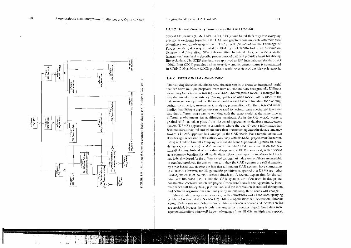
Large-scale 3D Data Integration: Challenges and Opportunities 1 Bridging the Worlds of CAD and GIs 31
1.4.1.2 Formal Geometry Semantics in the CAD Domain
Several file formats (DGN, DWG. X3D, SVG) have found their way into everyday practice as exchange formats in the CAD and graphics domain, each with their own advantages and disadvantages. The STEP project (STandard for the Exchange of Product model data) was initiated in 1984 by I S 0 TC184 lriduslrial Automation Systems and Integration, SC4 Subconirnittee Industrial Data, to create a single internatior~al standard to describe product model data and provide a basis for sharing life cycle data. The STEP standard was approved as I S 0 International Standard I S 0 10303. Pratt (2001) provides a short overview, and its current status is summarized in STEP (2004). Mason (2002) provides a useful overvicw of the life cycle aspects.
After solving the semantic dilferences, the next step is to create an integrated ~rlodel that can serve multiple purposes (from both a CAD arid CIS background). DilTere~~t views n~ay be defined on this representation. The integrated model is managed in a way that rnainlains consistency (during updates or when model data is added to the data management system). So the same model is used as the foundation for planning, design, construction, management, analysis, presentation, etc. The integrated modcl implics that different applications can be used to petionn these specialized tasks and also that different users can be working with the same model at the same time in different environments (or at different locations). As in the GIS world, where a gradual shift has taken place from file-based approaches to database management system (DBMS) approaches in situations whcre the use of (geo-) inrorn~ation has become more structural and where more than one person updatcs the data, a tendency t o w d a DBMS approach has emerged in the CAD world. For example, about two decades ago, when one of the authors was busy with his M.Sc. project (van Oosterom, 1985) at Fokker Aircraft Company, several different depru-tments (predesign, aero- dynamics, construction) needed access to the same CAD information on the new aircraft designs. Insbad of a file-based approach, a DBMS was used, which scrved as a common baseline for all applications. Back then, specific intcrl'aces to Oracle had to be developed for the different applications, but today some of these are available in standard products. Be that as it may, to date the CAD systems are still dominated by a file-based use, despite the fact that all modern CAD systems have connections to a DBMS. However, the 3D geometric prin~itives supported in a DBMS are rather limited, which is of course a serious drawback. A second explatration for the still dominant file-based use, is that the CAD systems are often used in design and construction contexts, which are project (or contract) based; see Appendix A. How- ever, when lull life cycle support matures and the information is (re)used throughout and between organizations (and not just by individuals), these needs will change.
Shwed data management does away with conversious and all the accornpariying problems (as illustrated in Section 1.2). Different applications will operate on (different views of) the same set of objects. So no data conversion is needed and inconsislencies we avoided, because there is only one source for a spccific object. Good data man- agement also offers other well-known advantages liom DBMSs: niulliple user support,
32 L.arge-scale 3D Data Integration: Challenges and Opportunities
transaction support, security and authorization, (spatial) data clustering and indexing, query optimiration, dislributed architectures, support for the concept of multiple views, maintenance of integrity conskaints (especially referential integrity, but also other types), and integration with othcr relevant information systems within an organization. In a nutshell. "island" automation will be abandoned, as company-wide information managcmerlt beco~ncs a reality. Though most current DBMSs suppott spatial data types (Oucle. DI32, Informix, Ingres, PostgreSQL, and MySQL, to namc just a few), thesc are not (yet) capable of supporting the higher geometry demands from CAD s y s t c ~ ~ ~ s . That said, it should not be that difficult to extend the DBMS with nrvre spatial dava typcs. l'he authors of this chapter were involved in extending Oracle with a new spatial d a t ~ type, the polyhedron (Arens et al., 2003). It should also bc possible to implement other required types, but it should be stressed, at the same time, that a DBMS alone is not the answer to bridging the gap between CAD and CIS. The prcrequirire is an integrated model, which is rich enough to support the semantics required or i~nplicd by [he different domains.
Thc DBMS can be considered as an implementation platform lor an integrated CAD-GIS 111ode1 (with difierent views). However, when exchanging information (or using services from other sources), the structured exchange of information beconles an important issue. The UML (OCL) models are the foundation for both the storage data rnodels (further described in the data defi~~ition languages (DDLs) of the DBMS) and the exchange data models. The latter have not becn addressed in this chaplcr, but they are vitally in~pvrtant in our network society. The extensible Markup Language (XML) can be used for the models containing the class descrip- tions at class level (XML schema document "xsd") und for the data at object instance levcl ("normal" XML document with data "xml"). XML documents also includc the geometric aspect of objects (e.g., LandXML, GML, X3D).
1.5 CONCLUSIONS
This chapter has explained the nccd to integrate CIS and CAD. Although such integration would offer great potcntial for the management of representations of real-world objects, it has been very difficult so far to use representations from GIS and CAD in one environment. The life cycle concept takes a central place in the integration: dil'fcrent represent:ltions or views of the same real-world object are needed throughout the life cyclc of an objcct (plan, construct, survey, maintain).
I t can already bc concluded from conversions within onc domain (GIS and CAD examples in Se~t ion 1.3) that geometric and semantic aspects both need to be taken into accou~rl. Tlrc sarne will he true for bridging the gap betwcen CIS and CAD systems. However, as both the semantics and the geometry may be more different thar~ witllin CIS or within CAD, the task is more challenging. At least two major dcveloprnenrs t r~c ncedcd to close the gap between CIS and CAD (which many users want to sce). Ttrc first is to perform a semantic analysis of the concepts of these "d~lfercnt" worlds m d , il' possible, develop a two-way translation between the two (or an integrated model with multiple views). Sccond, both GIS and CAD should base theil. data management on the samc technology, i.c., as proposed in this chapter, aspatial DBMS, which is co~nplianr will1 Open Geospatial(1SO) and CAD standards.
Bridging the Worlds of CAD and CIS 33
In this chapter we sketched the framework that is needcd to bridge the gap between CIS and CAD. First, a formal description is required of the semantics used in both domains. Thc preliminary steps were set out in this chapter. The next step is to design one central formal semantic that is compliant with both CIS and CAD sernantics. This formal semantic can be used in the factual integration of CIS and CAD, which should be implemented in an integrated data management structure based on the multiview model. This structure should bc well defined in a DBMS environment. 111 effect, this will then close the gap between CIS and CAD in thc future, and thc user can select his favorite tool for a specific task, operating on a view of the shared model managed by the Spatial DBMS. Of course, this assunlcs that the CIS and CAD tools will all be adapted to the spatial DBMS with the different (semantic) views. Also, this approach should be used irorn scratch, which will then makc the day-to-day practice of the cases mentioned in Section 1.2 much easie~.
ACKNOWLEDGMENTS
We would like to thank Justin Simpson and Daniel Edwards for their inspiring discussion, which startcd in the spring of 2003, on the differences (and affinities) between CAD and CIS. Thanks also to Wiln Bronsvoort and Sisi Zlatanova for their input in the carly stages of the discussion. Finally, we would like to thank Bentley for organizing the "geospatial research seminal" (23 May 2004) and the participants in this seminar for the inspiring discussions related to the topics such as large-scale 3D geo-information and the integration ol' CAD and CIS.
REFERENCES
Arens, C., Stoler, J.E., and. vall Oosterom, P.J.M., Modelling 3D spalial objects in a GcoDBMS using a 3D pi~nitive, in Pmceedings AGILE 2003, Lyon, France, April 2003.
Bcntley, Bentley MicroS~atio~~ GeoGraphics, http://www.bentley.com/, 2004. Bidarra, K. and Bro~lsvoort, W.F., Sernanlic feature modelling, Computer-Aided Design, 32.
20 1-225, 2000. Bro~~s\~oor~. W.F.., and Noor~, A., Multiple-view fea~ure modcling Ibr integral produc~ dcvel-
oprnent, Corr1putt.r--Aidrt1 Design, 36 (10); 929-946, 2004. Cowen, D.J.. GIS versus CAD versus DBMS: what are the dil-ferences? Photogrunlt~letr~c
Err~fneerir~g orid h'e~rlote Sensing, 54 (1 I), 1551-1555, 1988. DSTC, I?M, Sandpiper Sol~ware. Or~tology Definition Metarnodel, Reviscd sub~nission to
OMGIRFP adl2003-03-40, h1t~://www.omg.org/docs/ad/05-OI-Ol.pdf, LO January 2005.
Haasnool, H., Het gcbmik van hct FLI-MAP system voor trace kartering in versct~iller~dc industrien (in Dutch), KvAG themadag Laseralti~netric in Nedcrland. Vcrder kijkel~ dan het AHN ..., I I May 2000, http://www.gco.~udelft.nl/frs/lascrsca~dkvagll~aaa~loot. PPt.
klobbs, 1;. and Chan, C., AutoCAD as a cartographic t~aining 1001: u casc study, Cufnl~uter- Aided Design, 22 (3), 15 1-159, 1990.
Hoefsloot. M., 3D Geo-Informatie uit bestaande CAD rnodcllcn (ill Dutch), Case study report, TU Delft, scction GIS technology, 2003.
34 Large-scale 3D Data Integration: Challenges and Opportuni t ies
Hoinkes, K. and Lange, E., 3D for free-toolkitexpands visual dimensions in CIS, CIS World, 8 (7). 54-56, July 1995.
ICSM, 2002, Harrnonised dala manual - the harnlonised data model, I~~tergoverntnental Cotnmitlee on Surveying & Mapping (ICSM), 2002.
Kolbe, T.H. and I'lii~ner, L., Bridging the gap between GIS and CAAD - geornetry, reler- encing, rcpresenlalions, standards and semantic modelling, GlMIr~~err~a~iot~ul . 12-1 5. July 2004.
Lemmen, C., van der Molen, P., van Oosterom, I>., Ploeger. H., Quak, W., Stoter. J., and Zevenhergzn, J., A niodular standard for tlie Cadnslral Domaill, in proceedings of Uigilal Eurth lrfonnulion Resources for Globul Sirstuirrabilin; Brno. Czech Republic, Seplernbcr 21-25, 2003.
Lee, S.1-I. and Lee, K., Partial entily struclure: a compact non-manifold boundarv reoresen- - . talion based on p'arLia1 topological erililics, in proceedings Solid Modelitr~, Ann Arbor. MI, 159-170, 2001.
Logan, T. and Bryanl, N.A., Spatial data sortware integration: nlerging CADICAMlMapping with GIS and iriiage processing, Phologrutntnelr-ic. Errcqrtreering arrd Hetnoru .Sensitz~, 53 (10). 1391-1395, 1987.
Maguire, D.J., lniproving CAD-CIS lnteroperability, An.News Orrline, http:l/www.esri.corn/ newslarcr1ewslwinterO203arlicles/improving-~adhtnl), January 2003.
Mason, H., STEP and tlie other SCS standards - a backbone for induatry, www.eslec.esa.nl/ co~~Serenceslaerospace-pde-2002/presenations SL1DES-APDE2002~i~ason~~t
MovaSagh, S.M., GISICAD convergence enhances mapping applications, GIS World, 8 (5), 41C47, 1995.
Ncwell, R.G. and Sanclia. T.L., Thc dilfcrence between CAD and GIS, Cotrlpuler-Aided Design. 22 (31, 131-135, 1990.
OGC, OpenGIS Co~isortiuln. The OpenGlS Absuact Spccilication, Topic I: Feature Geometry (IS0 1'1107 Spatial Sclic~na). Version 5. Herring, J.H., Ed., OpenGlS Project Docu- riicnl Nu~ubcr 01- 101, Wayland. MA, 2001.
OMG, 2002, Object Managerrlent Group, Unilied Modeling Language Specificalion (Action Sernaillics), UML 1.4 will1 action sernan~ics, Janualy 2002.
OMG, 2003. Object Managemen1 Group, Response to the UML 2.0 OCL KfP (Object Constraint Language). January 2003.
Prall, M.J., lntroducl~on to 1SO 10303 - the STEP Standard for producl data exchange, Joirr-rral of Compurit~g utrd It~forrrruriu!~ Scierlce in Engineering, I (I), 102-103, 2001.
Queensla~~d Government, Registrar of Titlea - Directions for the Preparation of Plans, Deparln~enl of Naiural Revources and Mines. version 3.3. 1 May 2003.
Scllutzberg, A., Bringing GIS lo CAD - A Developer's Challenge, GIS World, 8 (5), 48-54, 1995.
Sensc8, WorldToolKitB Release 10, hltp://www.sense8,com/products/wlk.html, 2004. Shepherd, I.D.H., Mapping with desktop CAD: n critical review, Computer-Aided De~igri, 22 (3),
1361150, 1990. S~nrtli, A., Dodge, M., and Doylc, S., Visuul Comrnut~rculion in Urban Planning and Urban
Design, Centre for Advanced Spatial Analysis, University College London, CASA chapter 2, June 1998.
STEP-on-a-page, www.mel.nist.gov/sc5/soap/soapgrf030407.pdf, 2004. Sun, M., Chen, J., and Ma, A., Construction of Corrlplex City Landscape with the support of
CAD Model, ISPKS Comm. V, WG V/6, lnlernutional Ar-cc/~i~,us of Phologrummerry, Kernole Set~srtrg utld Spaliul lr$ormu~ion Scrence (LSSN: 1682-1777. Volurne: XXX IV, Part no.: 5/W3), lt~lerrialionul Work~hop on Visuulization and Arrinrulion of h n d - Jcupe, Kunriiing, China, 26 February-I March 2002.
Bridging t h e Worlds of CAD and GIs 35
vari Oosleronl, P.J.M., Visualiseren van aerodynamischc gcgcvens (in Dutch), M.Sc. Thebis TU DelfL, Cotrrputer Science, October 1985.
Verbree, E., van Maren, G., Janscn, F., and Kraak, M-.I., Interaction in virlual world views, linking 3D GIS withVK, lntertzutionul Journal ofGeogruphicu1 IrrJbr-nrutiorr Scirrrcc,, 13 (4). 385-396, 1999.
Voasclman, G. and Dijkrnan, S., 3D Building model reconslruction from point clouds and ground plans, lnferriationul Archives of l'hologrutnmetry and Kurfrole Surr.sirrg, XXXlV-3lW4: 3 7 4 3 , 2 0 0 1.
W3C, World Wide Web Consortium. OWL Web O~itology Language (Ovcl-view), Wic Rec- ommcndation, 10 February 2004.
Wonka, P. and Schmalstieg, D., Occluder shadows for rasl walklhroughs of urban environ- ments, Computer Graphics Forurn, 18 (3). Blackwell Publishers, 1SSN: 1007-7055, 51-60, 1999.
Zlatanova, S., 3D Modeling for augmented reality, Proceedit~gs of [he 3rd lSPl<S Work~hol) on Dvnumic und Multidimensionul CIS, Bangkok, Thailand. 415420, 23-25 May 2001.
APPENDIX A: DIFFERENCES BETWEEN CAD AND GIS
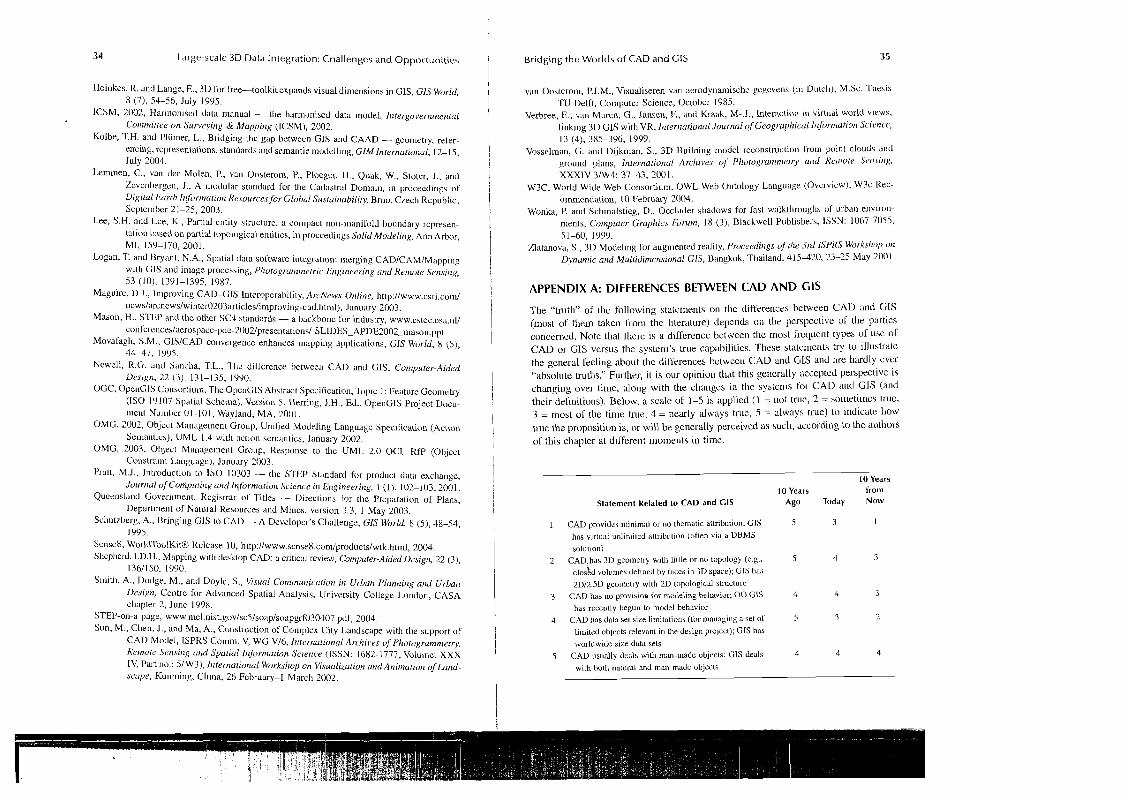
The "truth" of the following statements on the differences between CAD and GIS (most of them taken liom the literature) depends c ~ r ~ Lhe perspective of the parties concerncd. Note lhal lhcrc is a difference between the most frcquent types of uae of CAD or C;IS versus the syslern's true capabililies. 'These slalcn~erlls try to illuslrale the general reeling about the differences belwee11 CAD and GIS and :ue hardly ever "absolule truths." Further, it is our opinion that this generally accepted perspeclive is changing over time, along with the changes in the systcnls foor CAD and GIS (and their dehnitiot~s). Below, a scale of 1-5 is applied (I = not true, 2 = sometimes Lruc, 3 = most of the time true, 4 = nearly always true, 5 = always true) to indicate how true the propositioil is, ur will be generally perceived as such, according to the autllors of this chapler a1 different nlo~uents in time.
10 Years 10 Years frorn
Statement Related to CAD and CIS Ago Today NOW
1 CAD provides ~rrinimal or no thcn~atic atuibution; GIS 5 3 I
lias vlrtual unlinliled allribu~ion (often via a DBMS solutiori)
2 CAD,hes 311 geomelry wrllr lillle or no topology (e.g., 5 4 3
closkd volumes delined by faccs In 3D space); CIS has 2Dl2.5D geolllelry with 2D Lopological atlucture
3 CAD h a no prov~aioa for modeling behaviol; 00 CIS 4 4 3
has recently begun to model behavior 4 CAD has data sel size limitations (for rnanaging a set of 5 3 2
li~iiitcd objects relevant In the design project); CIS has worldwide size data sets
5 CAD usually deals with man-made objccts; GIS deals 4 4 4
with hoth natural and rrlarl-made object?
36 L a r g e - s c a l e 3D Data I n t e g r a t ~ o n : C h a l l e n g e s a n d O p p o r t u n i t i e s
10 Years 10 Years from
Statement Related to C A D and C IS Ago Today N o w
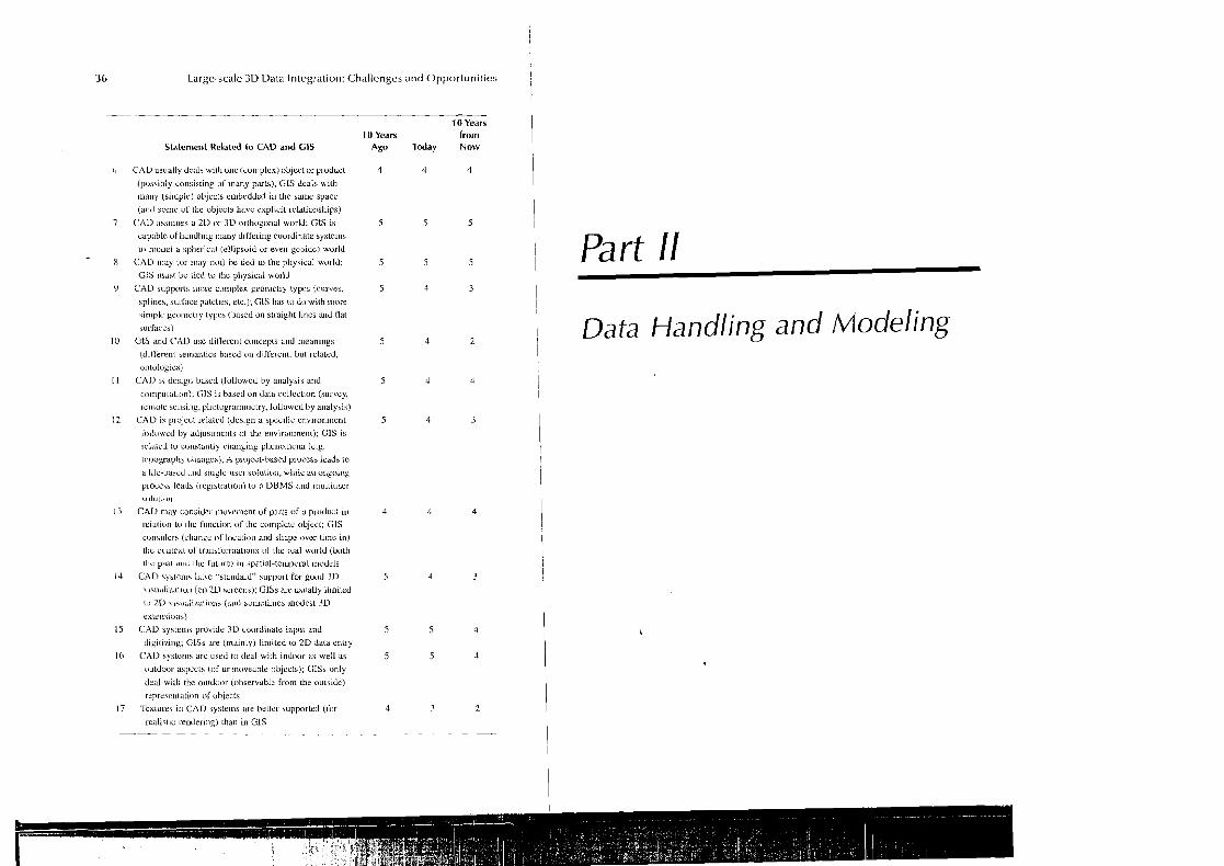
o CAD usually dcvla wllll one (conlple?.) object or product 4 4 4 (posalbly consisting oT Inany pals) . G I s deals with
many (si~rrple) objecls ernbedded in the same space
(and sorrrc of the objecls havc cxpllcil lelalionships)
7 CALI assurnea a 211 or 3D o~lhogonal world; G1S is 5 5 5
capable of handling nrany diife~ing coordinate syslerns
lo nn>del a s p h e ~ ~ c ; ~ l (elljpsuid or evcu gcuidc) wurld
- 8 CAI) ]nay (or 11r;ly not) be lied to the phya~cal wo~ ld ; 5 5 5
CIS 111usr bc tied to thc physical world
CAD supports Iiiure complex geometry typcs (curves,
splines, aurL~ce patches, elc.); CIS has to do with inore
uimplc gcalnclry [yllrs (bascd on srra~ght lines and Rat
surTaces)
CitS and CAI) use dillerent concepts alrd meanings
(difrcreot setnal~lics bnscd a11 d~f l 'c~el~l . but rclaled,
ontologicsj
CAI) IS deslgt~ bascd (followed by analysis and
conrputalron): (;IS is based on data collcct~on (sulvcy.
sclnote scnsing, photugrarnmetry, followed by analysis)
CAD is ploject related (deslgn o specific envi~onment
followcd by adlustlrlcnts o i thc ~ t~v~ron rnen t ) ; CIS i b
]elated to colrstanlly changing phenomena (e.g.,
t c~pog re~ l~ ) ~ l ~ a u g e a ) , A projcct-based proczss leads to
a lile-based and single-usel solution, whilc an ongoing
proceis leads (registration) lo a DBMS and lnultiuser
<oluliao
CAD may conaidcr movcment of pu t s of a product in
~ e l a t ~ o n lo lire fnncrion of the complete rlbject; GlS
considers (change o l locatii,n and shape over time in)
l l ~ c cuntext of Lranslormations of Ihe seal world (both thc past rl~id he Cu~ure) In spat~al-terr~pornl rnodels
CAD systems habe "stand;~~d" suppoll for good D \isuuli/.atiun (on2U hc~eens); GlSs are usually l ~ ~ n i l e d
to 2D viaual~rnt~onb (and so~r~r l imea nodes st i D
extensions)
CAD bytent\ provide i D ~oordirratr input and
dipili~ing; ClSs are (mainly) lilriitrd lo 2 D dilW errlry
CAT) syslcois arc used to deal wilh indoor as well as
outdoor aspects (of un~noveable objects); GISs only
deal wit11 the outdoor (observable from the outaide)
~.epreacrrlatiun o l objects
Tcxlu~cs rn CAD systems ale bellel supported (Cur
rcalist~c r e n d e n n ~ ) than io G1S
Part /I
( I Data Handling and Modeling