Embed Size (px)
Citation preview
Review
Received: 14 December 2010, Revised: 16 February 2011, Accepted: 16 February 2011, Published online in Wiley Online Library: 2011
(wileyonlinelibrary.com) DOI: 10.1002/cmmi.443
332
Photoacoustic tomography: fundamentals,advances and prospects†
Junjie Yaoa and Lihong V. Wanga*
Optical microscopy has been contributing to the dev
Contrast M
elopment of life science for more than three centuries. However,due to strong optical scattering in tissue, its in vivo imaging ability has been restricted to studies at superficial depths.Advances in photoacoustic tomography (PAT) now allow multiscale imaging at depths from sub‐millimeter to severalcentimeters, with spatial resolutions from sub‐micrometer to sub‐millimeter. Because of this high scalability and itsunique optical absorption contrast, PAT is capable of performing anatomical, functional, molecular and fluid‐dynamicimaging at various system levels, and is playing an increasingly important role in fundamental biological research andclinical practice. This review discusses recent technical progress in PAT and presents corresponding applications. Itends with a discussion of several prospects and their technical challenges. Copyright © 2011 John Wiley & Sons, Ltd.
Keywords: photoacoustic tomography; photoacoustic microscopy; photoacoustic computed tomography; photoacousticendoscopy; multiscale imaging; optical absorption contrast
* Correspondence to: L. V. Wang, Optical Imaging Laboratory, Department ofBiomedical Engineering, Washington University in St Louis, Campus Box 1097,One Brookings Drive, St Louis, MO 63130‐4899, USA.E‐mail: [email protected]
a J. Yao, L. V. WangOptical Imaging Laboratory, Department of Biomedical Engineering,Washington University in St Louis, Campus Box 1097, One Brookings Drive,St Louis, MO 63130‐4899, USA
† This article is published in Contrast Media and Molecular Imaging as part ofthe special issue on Photoacoustic Imaging, edited by Dr. Gregory Lanza,Department of Medicine, Washington University Medical Hospital.
1. INTRODUCTION
By zooming in on tiny features, optical microscopy has driventhe development of life science. However, no matter howsophisticated the optical microscope, its imaging signal fadesexponentially with imaging depth (1,2). As a photon travelsthrough tissue, multiple scattering events eventually lead torandomization of its propagation direction, i.e. photon diffusion,and thus blur the image (3). The mean propagation distance fora photon to diffuse is termed the transport mean free path(TMFP), which is typically 1mm in tissue (2). No existing opti-cal microscopy technologies can penetrate beyond one TMFP,where many biological processes and diseases occur. Therefore,there is a need for noninvasive in vivo imaging with high res-olution in deep tissue.
Photoacoustic tomography (PAT), an emerging powerfuloptical imaging modality using optical absorption contrast andultrasonic resolution, has broken through the fundamental barrierof one TMFP imaging depth (2,4–9). Most importantly, all the keycharacteristics of PAT are highly scalable. PAT has become one ofthe fastest growing fields in biomedical imaging (7). To avoidoverlappingwith recent review articles, this reviewmostly focuseson progress since the second half of year 2009. It is organized inthe following order: (i) fundamentals of the photoacoustic effectand photoacoustic imaging; (ii) multiscale PAT systems, based ontheir image formationmechanisms; (iii) anatomical and functionalPAT using intrinsic contrasts; (iv) molecular and chemical PATusing exogenous contrasts; (v) PAT of fluid dynamics; and (vi)prospects and challenges for PAT development in the near future.
2. FUNDAMENTALS OFPHOTOACOUSTIC TOMOGRAPHY
Based on the photoacoustic effect, discovered by Alexander G.Bell in 1880 (2), the principle of PAT is illustrated in Fig. 1.Typically, the PA effect starts from a target within tissueirradiated by a short laser pulse. The pulse energy is partially
edia Mol. Imaging 2011, 6 332–345 Copyri
absorbed by the target and converted into heat, which gen-erates a local transient temperature rise, followed by a localpressure rise through thermo‐elastic expansion. The pressurepropagates as ultrasonic waves, termed PA waves, and isdetected by ultrasonic transducers placed outside the tissue. APA image is then formed by resolving the origins of the ul-trasonic waves from their arrival times. Because the PA signalamplitude is proportional to the product of the local absorptioncoefficient and local fluence, PAT is essentially listening to theoptical absorption contrast of tissue. Meanwhile, because PATuncouples signal generation and detection, the diffusedphotons also contribute to the resultant PA signals withoutdegrading the signal quality. For biological tissue, becauseultrasonic scattering is about two to three orders of magnitudeweaker than optical scattering, PAT can achieve high spatialresolution deep in tissue. In addition, unlike other coherentimaging techniques, PAT is speckle free (10).
3. MULTISCALE PHOTOACOUSTICTOMOGRAPHY SYSTEMS
From organelles to organs, currently, PAT is the only imagingmodality spanning the microscopic and macroscopic worlds. Thehigh scalability of PAT is achieved by trading off imagingresolutions and penetration depths (11). Higher acoustic
ght © 2011 John Wiley & Sons, Ltd.
Biography
Dr Lihong Wang earned his Ph.D. degree at Rice University, Houston, Texas under the tutelage of Robert Curl,Richard Smalley and Frank Tittel and currently holds the Gene K. Beare Distinguished Professorship ofBiomedical Engineering at Washington University in St Louis. His book entitled Biomedical Optics: Principles andImaging, one of the first textbooks in the field, won the 2010 Joseph W. Goodman Book Writing Award. He alsocoauthored a book on polarization and edited the first book on photoacoustic tomography. He serves as theEditor‐in‐Chief of the Journal of Biomedical Optics. Professor Wang has published >230 peer‐reviewed journalarticles and delivered >255 keynote, plenary or invited talks. He is a Fellow of the American Institute for Medicaland Biological Engineering, the Optical Society of America, the Institute of Electrical and Electronics Engineersand the Society of Photo‐Optical Instrumentation Engineers. He chairs the annual conference on Photons plusUltrasound, and chaired the 2010 Gordon Conference on Lasers in Medicine and Biology and the 2010 OSATopical Meeting on Biomedical Optics. He is a chartered member on an NIH Study Section. Wang is the foundingchair of the scientific advisory boards for two companies commercializing his inventions. He received FIRSTand CAREER awards. He has received 27 research grants as the principal investigator with a cumulative budgetof >$30 million. His laboratory invented or discovered the dark‐field confocal photoacoustic microscopy (PAM),optical‐resolution PAM, photoacoustic Doppler effect, photoacoustic reporter gene imaging, focused scanningmicrowave‐induced thermoacoustic tomography, the universal photoacoustic or thermoacoustic reconstructionalgorithm, frequency‐swept ultrasound‐modulated optical tomography, sonoluminescence tomography,Mueller‐matrix optical coherence tomography, optical coherence computed tomography and oblique‐incidencereflectometry. In particular, PAM broke through the long‐standing diffusion limit to the penetration ofconventional optical microscopy and reached super‐depths for noninvasive biochemical, functional andmolecular imaging in living tissue at high resolution. Professor Wang’s Monte Carlo model of photon transportin scattering media is used worldwide.
PHOTOACOUSTIC TOMOGRAPHY: REVIEW
frequency contributes to higher spatial resolution, but is atten-uated more by tissue, thus resulting in a shallower penetrationdepth, and vice versa. In addition, optical attenuation is anotherlimiting factor for penetration depth, since PA waves aregenerated only where photons can reach. According to theirimaging formation mechanisms, PAT systems can be classifiedinto four categories: raster‐scan based photoacoustic microscopy(PAM), inverse‐reconstruction based photoacoustic computedtomography (PACT), rotation‐scan based photoacoustic endos-copy (PAE) and hybrid PAT systems with other imagingmodalities. A thorough side‐by‐side comparison of differentPAT systems can be found in recent review articles (9,11).
3.1. Raster‐scan based photoacoustic microscopy
By using a single focused ultrasonic transducer, usually placedconfocally with the irradiation laser beam, PAM forms a 1Dimage at each position, where the flight time of the ultrasoundsignal provides depth information. A 3D image is thengenerated by piecing together the 1D images obtained fromraster scanning, and thus no inverse reconstruction algorithm is
Figure 1. Illustration of the photoacoustic (PA) effect and PA imaging.
Contrast Media Mol. Imaging 2011, 6 332–345 Copyright © 2011 John
needed. PAM has two forms, based on its focusing mechanism.In acoustic‐resolution photoacoustic microscopy (AR‐PAM), theoptical focus is usually expanded wider than the acoustic focus,and thus acoustic focusing provides the system resolution(Fig. 2A) (12,13). Because the resolution is not affected by opticalscattering, by using a focused ultrasonic transducer with a50MHz central frequency and a 70% nominal bandwidth, atransverse resolution of 15 µm and axial resolution of 45 µmhave been achieved with a maximum penetration depth of3mm in live animals. However, to further improve the resolutionby increasing the acoustic frequency is quite challenging,because of the strong acoustic attenuation at high frequencies(14). The other form of PAM, termed optical‐resolution photo-acoustic microscopy (OR‐PAM), has an optical focus muchtighter than the acoustic focus, and thus the system resolution isprovided by optical focusing. Since the optical wavelength ismuch shorter than the acoustic wavelength, OR‐PAM can easilyachieve high spatial resolution, down to the micrometer or evensub‐micrometer scale (Fig. 2B) (14,15). However, like traditionaloptical microcopy, OR‐PAM generally obeys the one TMFPlimitation due to photon scattering, which, however, is stilldeeper than the acoustic solution mentioned above.
PAM usually suffers from slow imaging speed due to rasterscanning. To improve this, different scanning mechanisms havebeenproposed to replace the traditionalmechanical scanning. Theseinclude optical scanning using Galvo mirrors (~2Hz frame rate) (16),mechanical scanning using a voice‐coil motor (~15Hz frame rate)(17) and hybrid scanning with optical scanning on one axis andmechanical scanning on the other axis (~6Hz frame rate) (18).
33
3.2. Inverse‐reconstruction based photoacousticcomputed tomography
Despite its high spatial resolution and improved imagingspeed, PAM usually has a limited focal depth and is not yetcapable of video‐rate imaging (19). In contrast, PACT is typically
Wiley & Sons, Ltd. wileyonlinelibrary.com/journal/cmmi
3
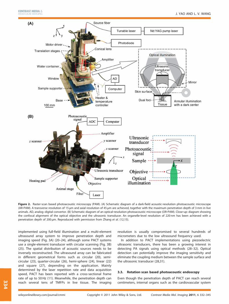
Figure 2. Raster‐scan based photoacoustic microscopy (PAM). (A) Schematic diagram of a dark‐field acoustic‐resolution photoacoustic microscope(AR‐PAM). A transverse resolution of 15 µm and axial resolution of 45 µm are achieved, together with the maximum penetration depth of 3mm in liveanimals. AD, analog–digital convertor. (B) Schematic diagram of an optical‐resolution photoacoustic microscope (OR‐PAM). Close‐up: diagram showingthe confocal alignment of the optical objective and the ultrasonic transducer. An organelle‐level resolution of 220 nm has been achieved with apenetration depth of 200 µm. Reproduced with permission from Zhang et al. (12,15).
J. YAO AND L. V. WANG
334
implemented using full‐field illumination and a multi‐elementultrasound array system to improve penetration depth andimaging speed (Fig. 3A) (20–24), although some PACT systemsuse a single‐element transducer with circular scanning (Fig. 3B)(25). The spatial distribution of acoustic sources needs to beinversely reconstructed. The ultrasound array can be fabricatedin different geometrical forms such as circular (20), semi‐circular (23), quarter‐circular (26), hemi‐sphere (24), linear (22)and square (27), depending on the application. Mainlydetermined by the laser repetition rate and data acquisitionspeed, PACT has been reported with a cross‐sectional framerate of up to 50Hz (11). Meanwhile, the penetration depth canreach several tens of TMFPs in live tissue. The imaging
Copyright © 2011 Johnwileyonlinelibrary.com/journal/cmmi
resolution is usually compromised to several hundreds ofmicrometers due to the low ultrasound frequency used.In addition to PACT implementations using piezoelectric
ultrasonic transducers, there has been a growing interest indetecting PA signals using optical methods (28–32). Opticaldetection can potentially improve the imaging sensitivity andeliminate the coupling medium between the sample surface andthe ultrasonic transducer (28,31).
3.3. Rotation‐scan based photoacoustic endoscopy
Even though the penetration depth of PACT can reach severalcentimeters, internal organs such as the cardiovascular system
Contrast Media Mol. Imaging 2011, 6 332–345Wiley & Sons, Ltd.
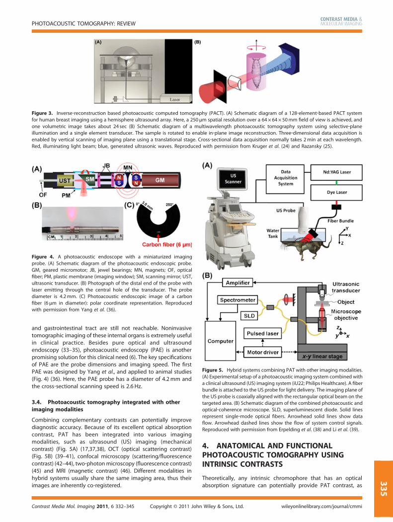
Figure 3. Inverse‐reconstruction based photoacoustic computed tomography (PACT). (A) Schematic diagram of a 128‐element‐based PACT systemfor human breast imaging using a hemisphere ultrasound array. Here, a 250 µm spatial resolution over a 64 × 64× 50mm field of view is achieved, andone volumetric image takes about 24 sec (B) Schematic diagram of a multiwavelength photoacoustic tomography system using selective‐planeillumination and a single element transducer. The sample is rotated to enable in‐plane image reconstruction. Three‐dimensional data acquisition isenabled by vertical scanning of imaging plane using a translational stage. Cross‐sectional data acquisition normally takes 2min at each wavelength.Red, illuminating light beam; blue, generated ultrasonic waves. Reproduced with permission from Kruger et al. (24) and Razansky (25).
Figure 4. A photoacoustic endoscope with a miniaturized imagingprobe. (A) Schematic diagram of the photoacoustic endoscopic probe.GM, geared micromotor; JB, jewel bearings; MN, magnets; OF, opticalfiber; PM, plastic membrane (imaging window); SM, scanning mirror; UST,ultrasonic transducer. (B) Photograph of the distal end of the probe withlaser emitting through the central hole of the transducer. The probediameter is 4.2mm. (C) Photoacoustic endoscopic image of a carbonfiber (6 μm in diameter): polar coordinate representation. Reproducedwith permission from Yang et al. (36).
Figure 5. Hybrid systems combining PAT with other imaging modalities.(A) Experimental setup of a photoacoustic imaging system combined witha clinical ultrasound (US) imaging system (iU22; Philips Healthcare). A fiberbundle is attached to the US probe for light delivery. The imaging plane ofthe US probe is coaxially aligned with the rectangular optical beam on thetargeted area. (B) Schematic diagram of the combined photoacoustic andoptical‐coherence microscope. SLD, superluminescent diode. Solid linesrepresent single‐mode optical fibers. Arrowhead solid lines show dataflow. Arrowhead dashed lines show the flow of system control signals.Reproduced with permission from Erpelding et al. (38) and Li et al. (39).
PHOTOACOUSTIC TOMOGRAPHY: REVIEW
33
and gastrointestinal tract are still not reachable. Noninvasivetomographic imaging of these internal organs is extremely usefulin clinical practice. Besides pure optical and ultrasoundendoscopy (33–35), photoacoustic endoscopy (PAE) is anotherpromising solution for this clinical need (6). The key specificationsof PAE are the probe dimensions and imaging speed. The firstPAE was designed by Yang et al., and applied to animal studies(Fig. 4) (36). Here, the PAE probe has a diameter of 4.2mm andthe cross‐sectional scanning speed is 2.6 Hz.
3.4. Photoacoustic tomography integrated with otherimaging modalities
Combining complementary contrasts can potentially improvediagnostic accuracy. Because of its excellent optical absorptioncontrast, PAT has been integrated into various imagingmodalities, such as ultrasound (US) imaging (mechanicalcontrast) (Fig. 5A) (17,37,38), OCT (optical scattering contrast)(Fig. 5B) (39–41), confocal microscopy (scattering/fluorescencecontrast) (42–44), two‐photonmicroscopy (fluorescence contrast)(45) and MRI (magnetic contrast) (46). Different modalities inhybrid systems usually share the same imaging area, thus theirimages are inherently co‐registered.
Contrast Media Mol. Imaging 2011, 6 332–345 Copyright © 2011 John
4. ANATOMICAL AND FUNCTIONALPHOTOACOUSTIC TOMOGRAPHY USINGINTRINSIC CONTRASTS
Theoretically, any intrinsic chromophore that has an opticalabsorption signature can potentially provide PAT contrast, as
Wiley & Sons, Ltd. wileyonlinelibrary.com/journal/cmmi
5
J. YAO AND L. V. WANG
336
long as appropriate irradiation wavelengths are applied and thesystem sensitivity is sufficient. Here, we review the currentlyused intrinsic contrasts, in the order of hemoglobin, melanin,water, lipid and nucleic acid.
4.1. Photoacoustic tomography of hemoglobin
In the visible spectral range (450–600 nm), oxyhemoglobin(HbO2) and deoxyhemoglobin (HbR) account for most of theoptical absorption in blood (47). The absorption coefficient ratiobetween blood and surrounding tissues is as high as six ordersof magnitude; hence, PAT can image with nearly no backgroundRBC‐perfused vasculature, the functional vascular subset re-sponsible for tissue oxygen supply. Furthermore, because PAsignal amplitudes depend on the concentrations of HbO2 (Cox)and HbR (Cde), spectroscopic measurements can be performedto quantify Cox and Cde by solving linear equations (48). From Coxand Cde, the total hemoglobin concentration (HbT) and oxygen
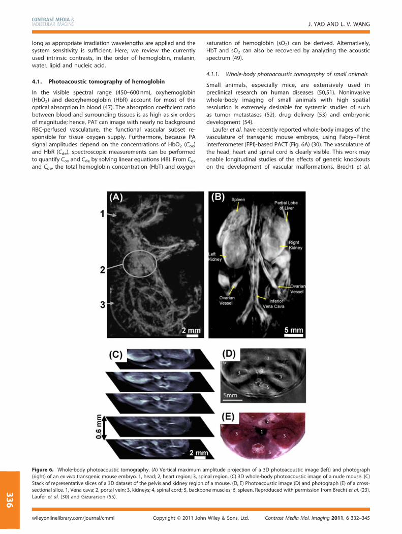
Figure 6. Whole‐body photoacoustic tomography. (A) Vertical maximum a(right) of an ex vivo transgenic mouse embryo. 1, head; 2, heart region; 3, spiStack of representative slices of a 3D dataset of the pelvis and kidney regionsectional slice. 1, Vena cava; 2, portal vein; 3, kidneys; 4, spinal cord; 5, backboLaufer et al. (30) and Gizurarson (55).
Copyright © 2011 Johnwileyonlinelibrary.com/journal/cmmi
saturation of hemoglobin (sO2) can be derived. Alternatively,HbT and sO2 can also be recovered by analyzing the acousticspectrum (49).
4.1.1. Whole‐body photoacoustic tomography of small animals
Small animals, especially mice, are extensively used inpreclinical research on human diseases (50,51). Noninvasivewhole‐body imaging of small animals with high spatialresolution is extremely desirable for systemic studies of suchas tumor metastases (52), drug delivery (53) and embryonicdevelopment (54).Laufer et al. have recently reported whole‐body images of the
vasculature of transgenic mouse embryos, using Fabry–Pérotinterferometer (FPI)‐based PACT (Fig. 6A) (30). The vasculature ofthe head, heart and spinal cord is clearly visible. This work mayenable longitudinal studies of the effects of genetic knockoutson the development of vascular malformations. Brecht et al.
mplitude projection of a 3D photoacoustic image (left) and photographnal region. (C) 3D whole‐body photoacoustic image of a nude mouse. (C)of a mouse. (D, E) Photoacoustic image (D) and photograph (E) of a cross‐ne muscles; 6, spleen. Reproduced with permission from Brecht et al. (23),
Contrast Media Mol. Imaging 2011, 6 332–345Wiley & Sons, Ltd.
PHOTOACOUSTIC TOMOGRAPHY: REVIEW
reported the first in vivo whole‐body PAT images of a mouse(Fig. 6B) (23). The 3D tomography clearly shows blood‐richinternal organs such as the liver, spleen and kidneys, as well aslarge and small vasculature. Buehler et al. developed a novel PATscanner capable of fast whole‐body imaging in vivo (55). Thesystem has achieved cross‐sectional animal imaging with video‐rate data acquisition. Imaging performance was demonstrated
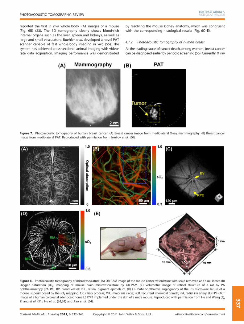
Figure 7. Photoacoustic tomography of human breast cancer. (A) Breast cimage from mediolateral PAT. Reproduced with permission from Ermilov et
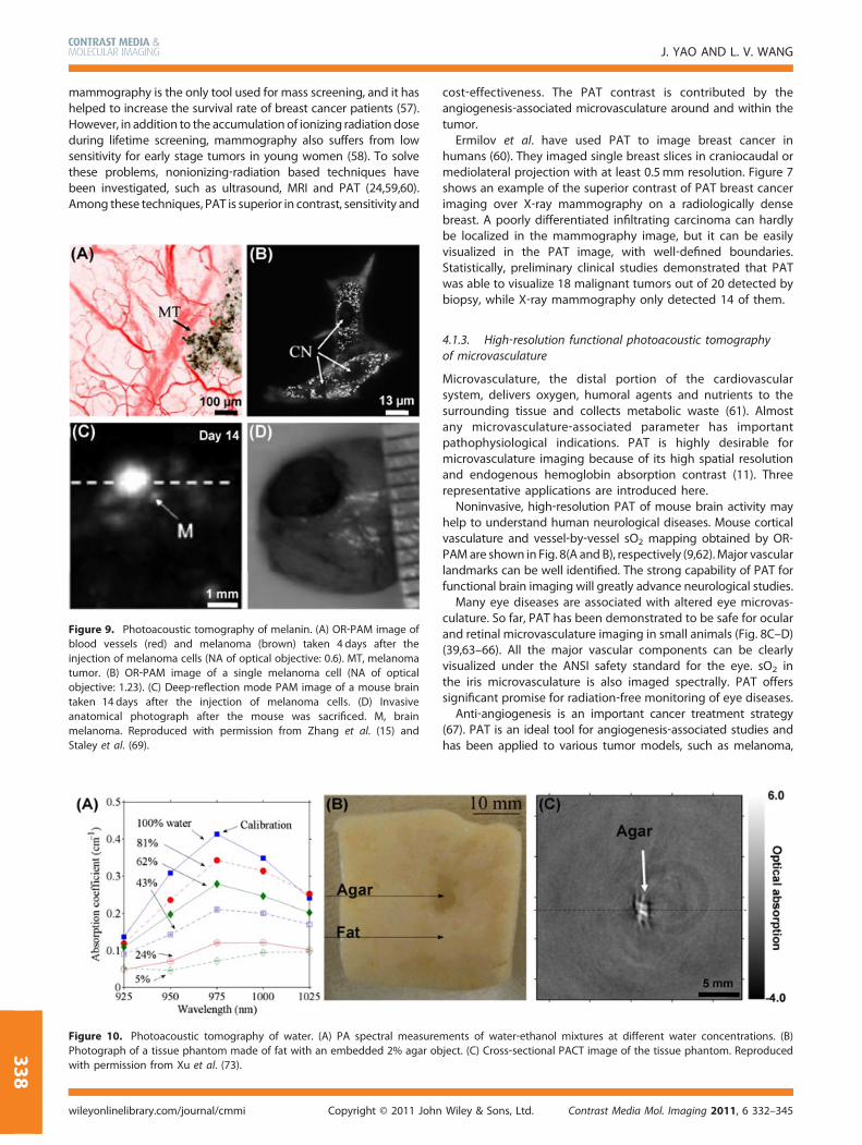
Figure 8. Photoacoustic tomography of microvasculature. (A) OR‐PAM imagOxygen saturation (sO2) mapping of mouse brain microvasculature byophthalmoscopy (PAOM). BV, blood vessel; RPE, retinal pigment epitheliummouse, superimposed by the sO2 mapping. CP, ciliary process; MIC, major irisimage of a human colorectal adenocarcinoma LS174T implanted under the skZhang et al. (31), Hu et al. (62,63) and Jiao et al. (64).
Contrast Media Mol. Imaging 2011, 6 332–345 Copyright © 2011 John
by resolving the mouse kidney anatomy, which was congruentwith the corresponding histological results (Fig. 6C–E).
4.1.2. Photoacoustic tomography of human breast
As the leading cause of cancer death amongwomen, breast cancercan be diagnosed earlier by periodic screening (56). Currently, X‐ray
ancer image from mediolateral X‐ray mammography. (B) Breast canceral. (60).
e of the mouse cortex vasculature with scalp removed and skull intact. (B)OR‐PAM. (C) Volumetric image of retinal structure of a rat by PA. (D) OR‐PAM ophthalmic angiography of the iris microvasculature of acircle; RCB, recurrent choroidal branch; RIA, radial iris artery. (E) FPI‐PACTin of a nude mouse. Reproduced with permission from Hu and Wang (9),
Wiley & Sons, Ltd. wileyonlinelibrary.com/journal/cmmi
337
J. YAO AND L. V. WANG
338
mammography is the only tool used for mass screening, and it hashelped to increase the survival rate of breast cancer patients (57).However, in addition to the accumulationof ionizing radiationdoseduring lifetime screening, mammography also suffers from lowsensitivity for early stage tumors in young women (58). To solvethese problems, nonionizing‐radiation based techniques havebeen investigated, such as ultrasound, MRI and PAT (24,59,60).Among these techniques, PAT is superior in contrast, sensitivity and
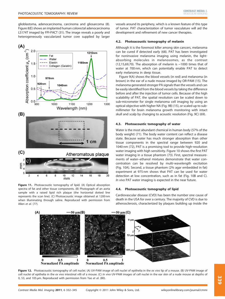
Figure 9. Photoacoustic tomography of melanin. (A) OR‐PAM image oblood vessels (red) and melanoma (brown) taken 4 days after theinjection of melanoma cells (NA of optical objective: 0.6). MT, melanomatumor. (B) OR‐PAM image of a single melanoma cell (NA of opticaobjective: 1.23). (C) Deep‐reflection mode PAM image of a mouse braintaken 14 days after the injection of melanoma cells. (D) Invasiveanatomical photograph after the mouse was sacrificed. M, brainmelanoma. Reproduced with permission from Zhang et al. (15) andStaley et al. (69).
Figure 10. Photoacoustic tomography of water. (A) PA spectral meaPhotograph of a tissue phantom made of fat with an embedded 2% agwith permission from Xu et al. (73).
Copyright © 2011wileyonlinelibrary.com/journal/cmmi
f
l
surear ob
John
cost‐effectiveness. The PAT contrast is contributed by theangiogenesis‐associated microvasculature around and within thetumor.Ermilov et al. have used PAT to image breast cancer in
humans (60). They imaged single breast slices in craniocaudal ormediolateral projection with at least 0.5mm resolution. Figure 7shows an example of the superior contrast of PAT breast cancerimaging over X‐ray mammography on a radiologically densebreast. A poorly differentiated infiltrating carcinoma can hardlybe localized in the mammography image, but it can be easilyvisualized in the PAT image, with well‐defined boundaries.Statistically, preliminary clinical studies demonstrated that PATwas able to visualize 18 malignant tumors out of 20 detected bybiopsy, while X‐ray mammography only detected 14 of them.
4.1.3. High‐resolution functional photoacoustic tomographyof microvasculature
Microvasculature, the distal portion of the cardiovascularsystem, delivers oxygen, humoral agents and nutrients to thesurrounding tissue and collects metabolic waste (61). Almostany microvasculature‐associated parameter has importantpathophysiological indications. PAT is highly desirable formicrovasculature imaging because of its high spatial resolutionand endogenous hemoglobin absorption contrast (11). Threerepresentative applications are introduced here.Noninvasive, high‐resolution PAT of mouse brain activity may
help to understand human neurological diseases. Mouse corticalvasculature and vessel‐by‐vessel sO2 mapping obtained by OR‐PAMare shown in Fig. 8(A and B), respectively (9,62).Major vascularlandmarks can be well identified. The strong capability of PAT forfunctional brain imaging will greatly advance neurological studies.Many eye diseases are associated with altered eye microvas-
culature. So far, PAT has been demonstrated to be safe for ocularand retinal microvasculature imaging in small animals (Fig. 8C–D)(39,63–66). All the major vascular components can be clearlyvisualized under the ANSI safety standard for the eye. sO2 inthe iris microvasculature is also imaged spectrally. PAT offerssignificant promise for radiation‐free monitoring of eye diseases.Anti‐angiogenesis is an important cancer treatment strategy
(67). PAT is an ideal tool for angiogenesis‐associated studies andhas been applied to various tumor models, such as melanoma,
ments of water‐ethanol mixtures at different water concentrations. (B)ject. (C) Cross‐sectional PACT image of the tissue phantom. Reproduced
Contrast Media Mol. Imaging 2011, 6 332–345Wiley & Sons, Ltd.
PHOTOACOUSTIC TOMOGRAPHY: REVIEW
glioblastoma, adenocarcinoma, carcinoma and gliosarcoma (8).Figure 8(E) shows an implanted human colorectal adenocarcinomaLS174T imaged by FPI‐PACT (31). The image reveals a poorly andheterogeneously vascularized tumor core supplied by larger
Figure 11. Photoacoustic tomography of lipid. (A) Optical absorptionspectra of fat and other tissue components. (B) Photograph of an aortasample with a raised lipid rich plaque (the horizontal dotted linerepresents the scan line). (C) Photoacoustic image obtained at 1200nmwhen illuminating through saline. Reproduced with permission fromAllen et al. (77).
Figure 12. Photoacoustic tomography of cell nuclei. (A) UV‐PAM image of ccell nuclei of epithelia in the ex vivo intestinal villi of a mouse. (C) In vivo UV0, 53, and 105 µm. Reproduced with permission from Yao et al. (80).
Contrast Media Mol. Imaging 2011, 6 332–345 Copyright © 2011 John
vessels around its periphery, which is a known feature of this typeof tumor. PAT characterization of tumor vasculature will aid thedevelopment and refinement of new cancer therapies.
4.2. Photoacoustic tomography of melanin
Although it is the foremost killer among skin cancers, melanomacan be cured if detected early (68). PAT has been investigatedfor noninvasive melanoma imaging using melanin, the light‐absorbing molecules in melanosomes, as the contrast(12,15,69,70). The absorption of melanin is ~1000 times that ofwater at 700 nm, which can potentially enable PAT to detectearly melanoma in deep tissue.
Figure 9(A) shows the blood vessels (in red) and melanoma (inbrown) in the ear of a nude mouse imaged by OR‐PAM (15). Themelanoma generated stronger PA signals than the vessels and canbe easily identified from the blood vessels by taking the differencebefore and after the injection of tumor cells. Because of the highscalability of PAT, the spatial resolution can be scaled down tosub‐micrometer for single melanoma cell imaging by using anoptical objective with higher NA (Fig. 9B) (15), or scaled up to sub‐millimeter for brain melanoma growth monitoring with intactskull and scalp by changing to acoustic resolution (Fig. 9C) (69).
4.3. Photoacoustic tomography of water
Water is the most abundant chemical in human body (57% of thebody weight) (71). The body water content can reflect a diseasestate. Because water has much stronger absorption than othertissue components in the spectral range between 920 and1040 nm (72), PAT is a promising tool to provide high‐resolutionwater imaging with high sensitivity. Figure 10 shows the first PATwater imaging in a tissue phantom (73). First, spectral measure-ments of water–ethanol mixtures demonstrate that water con-centration can be resolved by multi‐wavelength excitation(Fig. 10A). Second, a tissue phantom (2% agar embedded in fat)experiment at 975 nm shows that PAT can be used for waterdetection at low concentration, such as in fat (Fig. 10B and C).In vivo PAT water imaging is expected in the near future.
4.4. Photoacoustic tomography of lipid
Cardiovascular disease (CVD) has been the number one cause ofdeath in the USA for over a century. The majority of CVD is due toatherosclerosis, characterized by plaques building up inside the
ell nuclei of epithelia in the ex vivo lip of a mouse. (B) UV‐PAM image of‐PAM images of cell nuclei in the ear skin of a nude mouse at depths of
Wiley & Sons, Ltd. wileyonlinelibrary.com/journal/cmmi
339
J. YAO AND L. V. WANG
340
arterial wall (74). Lipid is a common constituent in atheroscleroticplaques, the location and area of which are closely related to theprogression of the disease. PAT is well suited for lipid imaging:compared with water‐based tissue components, lipid has adistinct absorption spectrum between 1150 and 1250 nm(Fig. 11A) (75–77). A recent advance in PAT lipid imaging wasreported by Allen et al. (77). A human aorta containing a raisedlipid‐rich plaque (Fig. 11B) was imaged at 1200 nm (Fig. 11C). Theplaque is clearly identified due to the strong absorption by lipid.The results demonstrate that spectroscopic PAT is a promisingtool for lipid detection in atherosclerosis.
4.5. Photoacoustic tomography of cell nuclei
Cell nuclei are organelles where major cell activities take place.Compared with those of normal cells, nuclei of cancer cells havefolded shapes and enlarged size (78). Imaging cell nuclei plays acritical role in cancer diagnosis. Traditional imaging of cell nucleineeds tissue sectioning and histological staining, which are notapplicable for in vivo studies. Because nucleic acids, the majorcomponents of DNA and RNA in cell nuclei, have strongabsorption in the ultraviolet range (79), PAT is a good choice forimaging cell nuclei using nucleic acids as intrinsic contrast.
By exciting DNA and RNA at 266 nm, Yao et al. have recentlyreported the first label‐free PA ex vivo and in vivo images of cellnuclei (Fig. 12) (80), termed UV‐PAM. Cell nuclei in the epitheliaof the mouse lip and the intestinal villi were imaged ex vivo(Fig. 12A and B). Cell nuclei in the ear skin of a nude mouse wereimaged in vivo at depths greater than 100 µm (Fig. 12C). UV‐PAMis cable of 3D noninvasive cell nuclei imaging without staining.
5. CHEMICAL AND MOLECULARPHOTOACOUSTIC TOMOGRAPHYUSING EXOGENOUS CONTRAST AGENTS
Even though the intrinsic contrasts in biological tissue arepromising, exogenous contrast agents can extend the power of
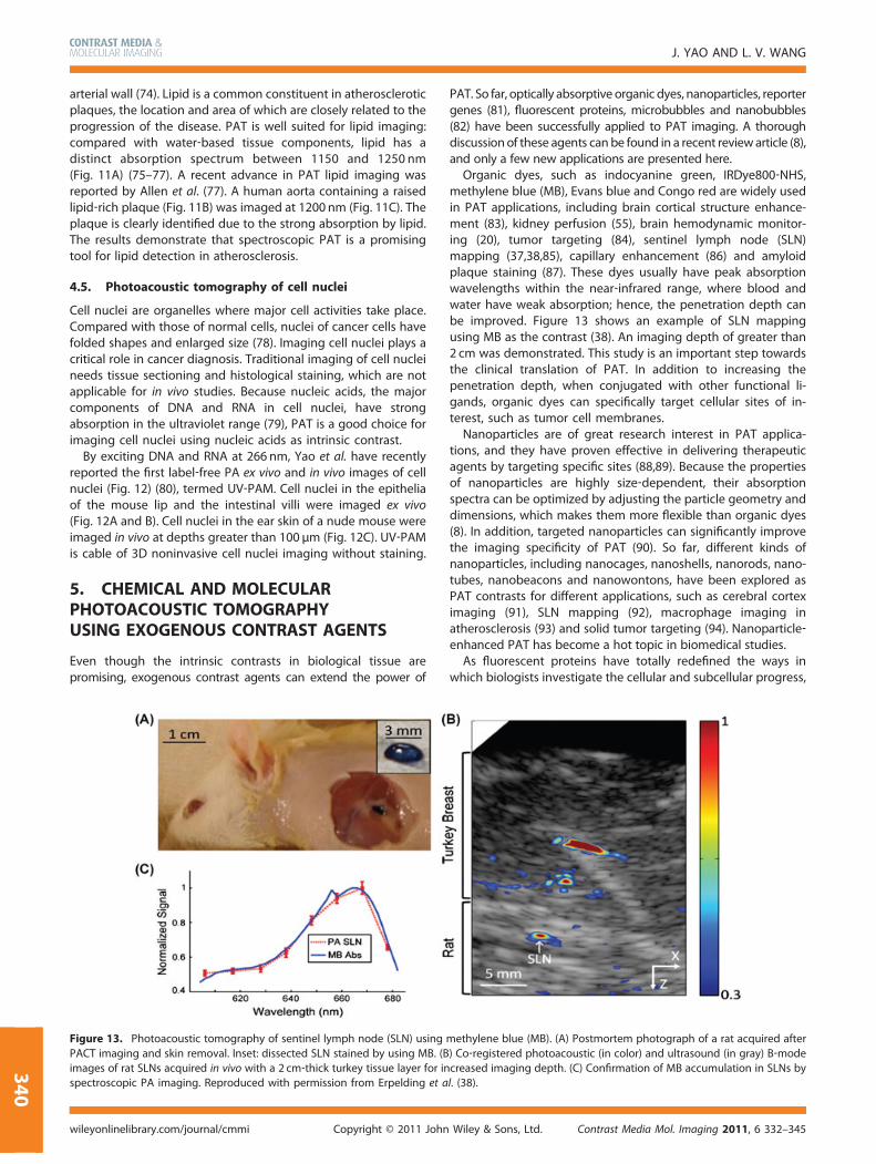
Figure 13. Photoacoustic tomography of sentinel lymph node (SLN) usingPACT imaging and skin removal. Inset: dissected SLN stained by using MB. (Bimages of rat SLNs acquired in vivo with a 2 cm‐thick turkey tissue layer for inspectroscopic PA imaging. Reproduced with permission from Erpelding et a
Copyright © 2011 Johnwileyonlinelibrary.com/journal/cmmi
PAT. So far, optically absorptive organic dyes, nanoparticles, reportergenes (81), fluorescent proteins, microbubbles and nanobubbles(82) have been successfully applied to PAT imaging. A thoroughdiscussionof these agents can be found in a recent review article (8),and only a few new applications are presented here.Organic dyes, such as indocyanine green, IRDye800‐NHS,
methylene blue (MB), Evans blue and Congo red are widely usedin PAT applications, including brain cortical structure enhance-ment (83), kidney perfusion (55), brain hemodynamic monitor-ing (20), tumor targeting (84), sentinel lymph node (SLN)mapping (37,38,85), capillary enhancement (86) and amyloidplaque staining (87). These dyes usually have peak absorptionwavelengths within the near‐infrared range, where blood andwater have weak absorption; hence, the penetration depth canbe improved. Figure 13 shows an example of SLN mappingusing MB as the contrast (38). An imaging depth of greater than2 cm was demonstrated. This study is an important step towardsthe clinical translation of PAT. In addition to increasing thepenetration depth, when conjugated with other functional li-gands, organic dyes can specifically target cellular sites of in-terest, such as tumor cell membranes.Nanoparticles are of great research interest in PAT applica-
tions, and they have proven effective in delivering therapeuticagents by targeting specific sites (88,89). Because the propertiesof nanoparticles are highly size‐dependent, their absorptionspectra can be optimized by adjusting the particle geometry anddimensions, which makes them more flexible than organic dyes(8). In addition, targeted nanoparticles can significantly improvethe imaging specificity of PAT (90). So far, different kinds ofnanoparticles, including nanocages, nanoshells, nanorods, nano-tubes, nanobeacons and nanowontons, have been explored asPAT contrasts for different applications, such as cerebral corteximaging (91), SLN mapping (92), macrophage imaging inatherosclerosis (93) and solid tumor targeting (94). Nanoparticle‐enhanced PAT has become a hot topic in biomedical studies.As fluorescent proteins have totally redefined the ways in
which biologists investigate the cellular and subcellular progress,
methylene blue (MB). (A) Postmortem photograph of a rat acquired after) Co‐registered photoacoustic (in color) and ultrasound (in gray) B‐modecreased imaging depth. (C) Confirmation of MB accumulation in SLNs byl. (38).
Contrast Media Mol. Imaging 2011, 6 332–345Wiley & Sons, Ltd.
PHOTOACOUSTIC TOMOGRAPHY: REVIEW
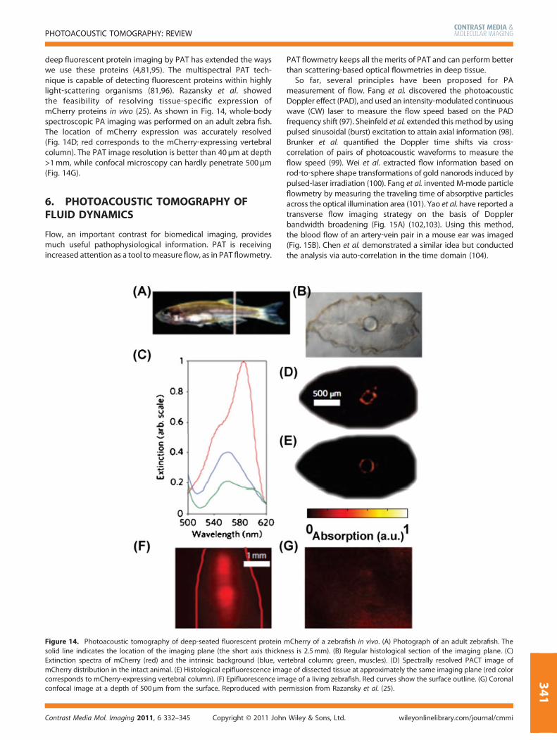
deep fluorescent protein imaging by PAT has extended the wayswe use these proteins (4,81,95). The multispectral PAT tech-nique is capable of detecting fluorescent proteins within highlylight‐scattering organisms (81,96). Razansky et al. showedthe feasibility of resolving tissue‐specific expression ofmCherry proteins in vivo (25). As shown in Fig. 14, whole‐bodyspectroscopic PA imaging was performed on an adult zebra fish.The location of mCherry expression was accurately resolved(Fig. 14D; red corresponds to the mCherry‐expressing vertebralcolumn). The PAT image resolution is better than 40 µm at depth>1mm, while confocal microscopy can hardly penetrate 500 µm(Fig. 14G).
6. PHOTOACOUSTIC TOMOGRAPHY OFFLUID DYNAMICS
Flow, an important contrast for biomedical imaging, providesmuch useful pathophysiological information. PAT is receivingincreased attention as a tool tomeasure flow, as in PAT flowmetry.
Figure 14. Photoacoustic tomography of deep‐seated fluorescent proteinsolid line indicates the location of the imaging plane (the short axis thicknExtinction spectra of mCherry (red) and the intrinsic background (blue, vemCherry distribution in the intact animal. (E) Histological epifluorescence imacorresponds to mCherry‐expressing vertebral column). (F) Epifluorescence imconfocal image at a depth of 500µm from the surface. Reproduced with pe
Contrast Media Mol. Imaging 2011, 6 332–345 Copyright © 2011 John
PAT flowmetry keeps all the merits of PAT and can perform betterthan scattering‐based optical flowmetries in deep tissue.
So far, several principles have been proposed for PAmeasurement of flow. Fang et al. discovered the photoacousticDoppler effect (PAD), and used an intensity‐modulated continuouswave (CW) laser to measure the flow speed based on the PADfrequency shift (97). Sheinfeld et al. extended this method by usingpulsed sinusoidal (burst) excitation to attain axial information (98).Brunker et al. quantified the Doppler time shifts via cross‐correlation of pairs of photoacoustic waveforms to measure theflow speed (99). Wei et al. extracted flow information based onrod‐to‐sphere shape transformations of gold nanorods induced bypulsed‐laser irradiation (100). Fang et al. invented M‐mode particleflowmetry by measuring the traveling time of absorptive particlesacross the optical illumination area (101). Yao et al. have reported atransverse flow imaging strategy on the basis of Dopplerbandwidth broadening (Fig. 15A) (102,103). Using this method,the blood flow of an artery‐vein pair in a mouse ear was imaged(Fig. 15B). Chen et al. demonstrated a similar idea but conductedthe analysis via auto‐correlation in the time domain (104).
mCherry of a zebrafish in vivo. (A) Photograph of an adult zebrafish. Theess is 2.5mm). (B) Regular histological section of the imaging plane. (C)rtebral column; green, muscles). (D) Spectrally resolved PACT image ofge of dissected tissue at approximately the same imaging plane (red colorage of a living zebrafish. Red curves show the surface outline. (G) Coronalrmission from Razansky et al. (25).
Wiley & Sons, Ltd. wileyonlinelibrary.com/journal/cmmi
341
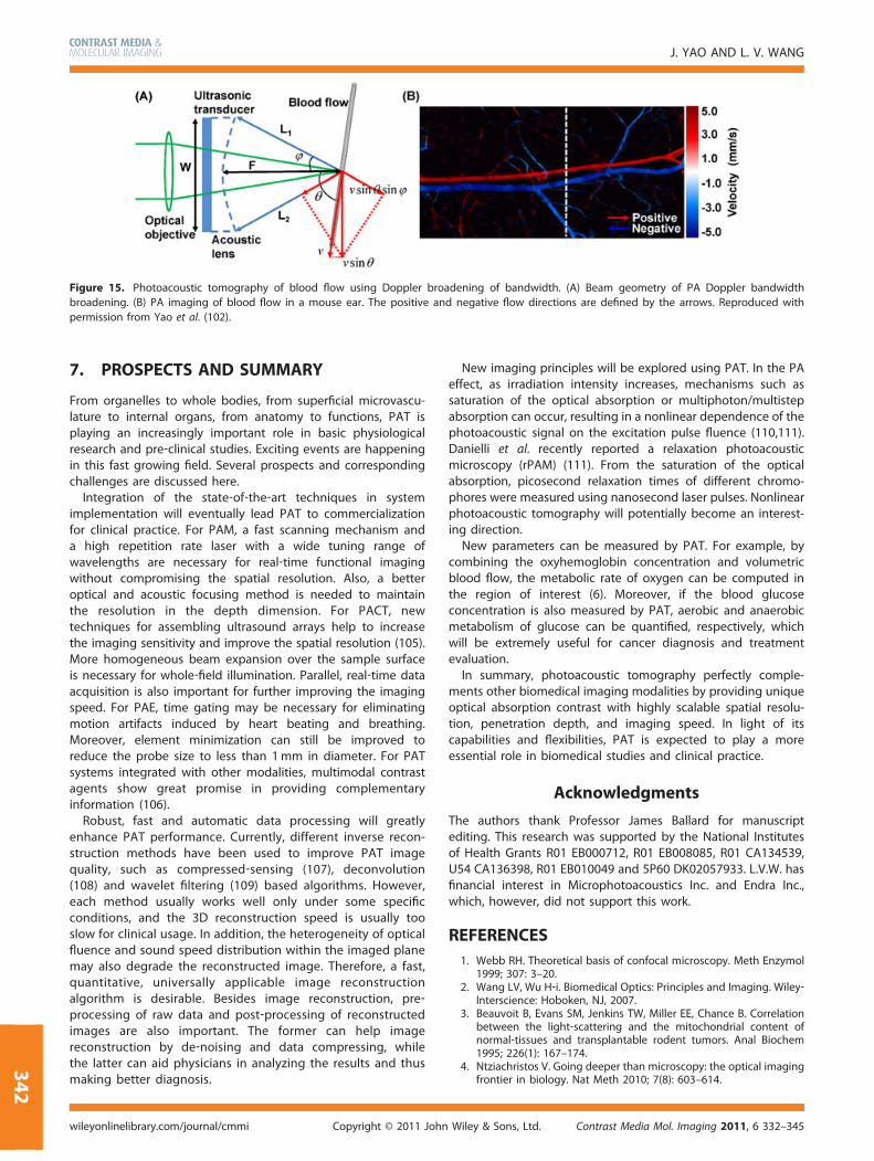
Figure 15. Photoacoustic tomography of blood flow using Doppler broadening of bandwidth. (A) Beam geometry of PA Doppler bandwidthbroadening. (B) PA imaging of blood flow in a mouse ear. The positive and negative flow directions are defined by the arrows. Reproduced withpermission from Yao et al. (102).
J. YAO AND L. V. WANG
342
7. PROSPECTS AND SUMMARY
From organelles to whole bodies, from superficial microvascu-lature to internal organs, from anatomy to functions, PAT isplaying an increasingly important role in basic physiologicalresearch and pre‐clinical studies. Exciting events are happeningin this fast growing field. Several prospects and correspondingchallenges are discussed here.
Integration of the state‐of‐the‐art techniques in systemimplementation will eventually lead PAT to commercializationfor clinical practice. For PAM, a fast scanning mechanism anda high repetition rate laser with a wide tuning range ofwavelengths are necessary for real‐time functional imagingwithout compromising the spatial resolution. Also, a betteroptical and acoustic focusing method is needed to maintainthe resolution in the depth dimension. For PACT, newtechniques for assembling ultrasound arrays help to increasethe imaging sensitivity and improve the spatial resolution (105).More homogeneous beam expansion over the sample surfaceis necessary for whole‐field illumination. Parallel, real‐time dataacquisition is also important for further improving the imagingspeed. For PAE, time gating may be necessary for eliminatingmotion artifacts induced by heart beating and breathing.Moreover, element minimization can still be improved toreduce the probe size to less than 1mm in diameter. For PATsystems integrated with other modalities, multimodal contrastagents show great promise in providing complementaryinformation (106).
Robust, fast and automatic data processing will greatlyenhance PAT performance. Currently, different inverse recon-struction methods have been used to improve PAT imagequality, such as compressed‐sensing (107), deconvolution(108) and wavelet filtering (109) based algorithms. However,each method usually works well only under some specificconditions, and the 3D reconstruction speed is usually tooslow for clinical usage. In addition, the heterogeneity of opticalfluence and sound speed distribution within the imaged planemay also degrade the reconstructed image. Therefore, a fast,quantitative, universally applicable image reconstructionalgorithm is desirable. Besides image reconstruction, pre‐processing of raw data and post‐processing of reconstructedimages are also important. The former can help imagereconstruction by de‐noising and data compressing, whilethe latter can aid physicians in analyzing the results and thusmaking better diagnosis.
Copyright © 2011 Johnwileyonlinelibrary.com/journal/cmmi
New imaging principles will be explored using PAT. In the PAeffect, as irradiation intensity increases, mechanisms such assaturation of the optical absorption or multiphoton/multistepabsorption can occur, resulting in a nonlinear dependence of thephotoacoustic signal on the excitation pulse fluence (110,111).Danielli et al. recently reported a relaxation photoacousticmicroscopy (rPAM) (111). From the saturation of the opticalabsorption, picosecond relaxation times of different chromo-phores were measured using nanosecond laser pulses. Nonlinearphotoacoustic tomography will potentially become an interest-ing direction.New parameters can be measured by PAT. For example, by
combining the oxyhemoglobin concentration and volumetricblood flow, the metabolic rate of oxygen can be computed inthe region of interest (6). Moreover, if the blood glucoseconcentration is also measured by PAT, aerobic and anaerobicmetabolism of glucose can be quantified, respectively, whichwill be extremely useful for cancer diagnosis and treatmentevaluation.In summary, photoacoustic tomography perfectly comple-
ments other biomedical imaging modalities by providing uniqueoptical absorption contrast with highly scalable spatial resolu-tion, penetration depth, and imaging speed. In light of itscapabilities and flexibilities, PAT is expected to play a moreessential role in biomedical studies and clinical practice.
Acknowledgments
The authors thank Professor James Ballard for manuscriptediting. This research was supported by the National Institutesof Health Grants R01 EB000712, R01 EB008085, R01 CA134539,U54 CA136398, R01 EB010049 and 5P60 DK02057933. L.V.W. hasfinancial interest in Microphotoacoustics Inc. and Endra Inc.,which, however, did not support this work.
REFERENCES1. Webb RH. Theoretical basis of confocal microscopy. Meth Enzymol
1999; 307: 3–20.2. Wang LV, Wu H‐i. Biomedical Optics: Principles and Imaging. Wiley‐
Interscience: Hoboken, NJ, 2007.3. Beauvoit B, Evans SM, Jenkins TW, Miller EE, Chance B. Correlation
between the light‐scattering and the mitochondrial content ofnormal‐tissues and transplantable rodent tumors. Anal Biochem1995; 226(1): 167–174.
4. Ntziachristos V. Going deeper than microscopy: the optical imagingfrontier in biology. Nat Meth 2010; 7(8): 603–614.
Contrast Media Mol. Imaging 2011, 6 332–345Wiley & Sons, Ltd.
PHOTOACOUSTIC TOMOGRAPHY: REVIEW
3
5. Wang LV. Tutorial on photoacoustic microscopy and computedtomography. IEEE J Sel Top Quant 2008; 14(1): 171–179.
6. Wang LV. Prospects of photoacoustic tomography. Med Phys 2008;35(12): 5758–5767.
7. Wang LV. Multiscale photoacoustic microscopy and computedtomography. Nat Phot 2009; 3(9): 503–509.
8. Kim C, Favazza C, Wang LHV. In vivo photoacoustic tomographyof chemicals: high‐resolution functional and molecular opticalimaging at new depths. Chem Rev 2010; 110(5): 2756–2782.
9. Hu S, Wang LV. Neurovascular photoacoustic tomography. FrontNeuroenerget 2010; 2: 10.
10. Guo ZJ, Li L, Wang LHV. On the speckle‐free nature ofphotoacoustic tomography. Med Phys 2009; 36(9): 4084–4088.
11. Hu S, Wang LV. Photoacoustic imaging and characterization of themicrovasculature. J Biomed Opt 2010; 15(1): 011101.
12. Zhang HF, Maslov K, Stoica G, Wang LHV. Functional photoacousticmicroscopy for high‐resolution and noninvasive in vivo imaging.Nat Biotechnol 2006; 24(7): 848–851.
13. Maslov K, Stoica G, Wang LHV. In vivo dark‐field reflection‐modephotoacoustic microscopy. Opt Lett 2005; 30(6): 625–627.
14. Maslov K, Zhang HF, Hu S, Wang LV. Optical‐resolution photo-acoustic microscopy for in vivo imaging of single capillaries. OptLett 2008; 33(9): 929–931.
15. Zhang C, Maslov K, Wang LHV. Subwavelength‐resolution label‐freephotoacoustic microscopy of optical absorption in vivo. Opt Lett2010; 35(19): 3195–3197.
16. Xie ZX, Jiao SL, Zhang HF, Puliafito CA. Laser‐scanning optical‐resolution photoacoustic microscopy. Opt Lett 2009; 34(12):1771–1773.
17. Harrison T, Ranasinghesagara J, Lu H, Zemp RJ. Fast‐scanningUltrasonic–Photoacoustic Biomicroscope: In Vivo Performance,Oraevsky AA, Wang LV (eds). SPIE: San Francisco, CA, 2010;75641X.
18. Rao B, Li L, Maslov K, Wang LH. Hybrid‐scanning optical‐resolutionphotoacoustic microscopy for in vivo vasculature imaging. Opt Lett2010; 35(10): 1521–1523.
19. Zhang HF, Maslov K, Wang LHV. Automatic algorithm for skinprofile detection in photoacoustic microscopy. J Biomed Opt 2009;14(2): 024050.
20. Li CH, Aguirre A, Gamelin J, Maurudis A, Zhu Q, Wang LV. Real‐time photoacoustic tomography of cortical hemodynamics in smallanimals. J Biomed Opt 2010; 15(1): 010509.
21. Gamelin J, Maurudis A, Aguirre A, Huang F, Guo PY, Wang LV,Zhu Q. A real‐time photoacoustic tomography system for smallanimals. Opt Express 2009; 17(13): 10489–10498.
22. Song LA, Maslov K, Shung KK, Wang LHV. Ultrasound‐array‐basedreal‐time photoacoustic microscopy of human pulsatile dynamicsin vivo. J Biomed Opt 2010; 15(2): 021303.
23. Brecht HP, Su R, Fronheiser M, Ermilov SA, Conjusteau A, Oraevsky AA.Whole‐body three‐dimensional optoacoustic tomography systemfor small animals. J Biomed Opt 2009; 14(6): 064007.
24. Kruger R, Lam R, Reinecke D, Del Rio S, Doyle R. Photoacousticangiography of the breast. Med Phys 2010; 37(11): 6096–6100.
25. Razansky D, Distel M, Vinegoni C, Ma R, Perrimon N, Koster RW,Ntziachristos V. Multispectral opto‐acoustic tomography of deep‐seated fluorescent proteins in vivo. Nat Photon 2009; 3(7): 412–417.
26. Gamelin J, Aguirre A, Maurudis A, Huang F, Castillo D, Wang LV, ZhuQ. Curved array photoacoustic tomographic system for smallanimal imaging. J Biomed Opt 2008; 13(2): 024007.
27. Balogun O, Regez B, Zhang HF, Krishnaswamy S. Real‐time full‐fieldphotoacoustic imaging using an ultrasonic camera. J Biomed Opt2010; 15(2): 021318.
28. Payne BP, Venugopalan V, Mikic BB, Nishioka NS. Optoacoustictomography interferometric detection using time‐resolved ofsurface displacement. J Biomed Opt 2003; 8(2): 273–280.
29. Nuster R, Holotta M, Kremser C, Grossauer H, Burgholzer P,Paltauf G. Photoacoustic microtomography using optical interfer-ometric detection. J Biomed Opt 2010; 15(2): 021307.
30. Laufer JG, Cleary JO, Zhang EZ, Lythgoe MF, Beard PC.Photoacoustic Imaging of Vascular Networks in Transgenic Mice,Oraevsky AA, Wang LV (eds). SPIE: San Francisco, CA, 2010;75641A.
31. Zhang EZ, Laufer JG, Pedley RB, Beard PC. In vivo high‐resolution3D photoacoustic imaging of superficial vascular anatomy. PhysMed Biol 2009; 54(4): 1035–1046.
Contrast Media Mol. Imaging 2011, 6 332–345 Copyright © 2011 John
32. Zhang E, Laufer J, Beard P. Backward‐mode multiwavelengthphotoacoustic scanner using a planar Fabry–Perot polymer filmultrasound sensor for high‐resolution three‐dimensional imagingof biological tissues. Appl Opt 2008; 47(4): 561–577.
33. Sergeev A, Gelikonov V, Gelikonov G, Feldchtein F, Kuranov R,Gladkova N, Shakhova N, Snopova L, Shakhov A, Kuznetzova I,Denisenko A, Pochinko V, Chumakov Y, Streltzova O. In vivoendoscopic OCT imaging of precancer and cancer states of humanmucosa. Opt Express 1997; 1(13): 432–440.
34. Kiesslich R, Burg J, Vieth M, Gnaendiger J, Enders M, Delaney P,Polglase A, McLaren W, Janell D, Thomas S, Nafe B, Galle PR,Neurath MF. Confocal laser endoscopy for diagnosing intraepithe-lial neoplasias and colorectal cancer in vivo. Gastroenterology2004; 127(3): 706–713.
35. Rosch T, Lorenz R, Braig C, Feuerbach S, Siewert JR, Schusdziarra V,Classen M. Endoscopic ultrasound in pancreatic tumor‐diagnosis.Gastrointest Endosc 1991; 37(3): 347–352.
36. Yang JM, Maslov K, Yang HC, Zhou QF, Shung KK, Wang LHV.Photoacoustic endoscopy. Opt Lett 2009; 34(10): 1591–1593.
37. Kim C, Erpelding TN, Jankovic L, Pashley MD, Wang LV. Deeplypenetrating in vivo photoacoustic imaging using a clinicalultrasound array system. Biomed Opt Express 2010; 1(1): 278–284.
38. Erpelding TN, Kim C, Pramanik M, Jankovic L, Maslov K, Guo Z,Margenthaler JA, Pashley MD, Wang LV. Sentinel lymph nodes inthe rat: noninvasive photoacoustic and US imaging with a clinicalUS system. Radiology 2010; 256(1): 102–110.
39. Li L, Maslov K, Ku G, Wang LV. Three‐dimensional combinedphotoacoustic and optical coherence microscopy for in vivomicrocirculation studies. Opt Express 2009; 17(19): 16450–16455.
40. Jiao SL, Xie ZX, Zhang HF, Puliafito CA. Simultaneous multimodalimaging with integrated photoacoustic microscopy and opticalcoherence tomography. Opt Lett 2009; 34(19): 2961–2963.
41. Zhang EZ, Laufer J, Povazay B, Alex A, Hofer B, Drexler W, Beard P.Multimodal Simultaneous Photoacoustic Tomography, OpticalResolution Microscopy, and OCT System, Oraevsky AA, Wang LV(eds). SPIE: San Francisco, CA, 2010; 75640U.
42. Zhang X, Jiang M, Fawzi AA, Li X, Shung KK, Puliafito CA, Zhang HF,Jiao S. Simultaneous dual molecular contrasts provided by theabsorbed photons in photoacoustic microscopy. Opt Lett 2010;35(23): 4018–4020.
43. Wang Y, Maslov K, Kim C, Hu S, Wang LHV. Integratedphotoacoustic and fluorescence confocal microscopy. IEEE T Bio‐Med Eng 2010; 57(10): 2576–2578.
44. Zhang HF, Wang J, Wei Q, Liu T, Jiao SL, Puliafito CA. Collectingback‐reflected photons in photoacoustic microscopy. Opt Express2010; 18(2): 1278–1282.
45. van Raaij ME, Lee M, Cherin E, Stefanovic B, Foster FS. FemtosecondPhotoacoustics: Integrated Two‐photon Fluorescence and Photo-acoustic Microscopy, Oraevsky AA, Wang LV (eds). SPIE: SanFrancisco, CA, 2010; 75642E.
46. Bouchard LS, Anwar MS, Liu GL, Hann B, Xie ZH, Gray JW, Wang XD,Pines A, Chen FF. Picomolar sensitivity MRI and photoacousticimaging of cobalt nanoparticles. Proc Natl Acad Sci USA 2009;106(11): 4085–4089.
47. Wang XD, Xie XY, Ku GN, Wang LHV. Noninvasive imaging ofhemoglobin concentration and oxygenation in the rat brain usinghigh‐resolution photoacoustic tomography. J Biomed Opt 2006;11(2): 024015.
48. Zhang HF, Maslov K, Sivaramakrishnan M, Stoica G, Wang LHV.Imaging of hemoglobin oxygen saturation variations in singlevessels in vivo using photoacoustic microscopy. Appl Phys Lett2007; 90(5): 053901.
49. Guo ZJ, Hu S, Wang LHV. Calibration‐free absolute quantification ofoptical absorption coefficients using acoustic spectra in 3Dphotoacoustic microscopy of biological tissue. Opt Lett 2010;35(12): 2067–2069.
50. Lewis JS, Achilefu S, Garbow JR, Laforest R, Welch MJ. Small animalimaging: current technology and perspectives for oncologicalimaging. Eur J Cancer 2002; 38(16): 2173–2188.
51. Weissleder R. Scaling down imaging: molecular mapping of cancerin mice. Nat Rev Cancer 2002; 2(1): 11–18.
52. Deroose CM, De A, Loening AM, Chow PL, Ray P, Chatziioannou AF,Gambhir SS. Multimodality imaging of tumor xenografts andmetastases in mice with combined small‐animal PET, small‐animalCT, and bioluminescence imaging. J Nucl Med 2007; 48(2): 295–303.
Wiley & Sons, Ltd. wileyonlinelibrary.com/journal/cmmi
43
J. YAO AND L. V. WANG
344
53. Gizurarson S. Animal‐models for intranasal drug delivery studies –a review article. Acta Pharm Nordica 1990; 2(2): 105–122.
54. Levine M, Tjian R. Transcription regulation and animal diversity.Nature 2003; 424(6945): 147–151.
55. Buehler A, Herzog E, Razansky D, Ntziachristos V. Video rateoptoacoustic tomography of mouse kidney perfusion. Opt Lett2010; 35(14): 2475–2477.
56. American Cancer Society. Hawaii Cancer Facts and Figures 2010: aSourcebook for Planning and Implementing Programs for CancerPrevention and Control. Honolulu, HI: Hawaii Pacific Division.,Cancer Research Center of Hawaii, Department of Health; 2010.
57. Schopper D, de Wolf C. How effective are breast cancer screeningprogrammes by mammography? Review of the current evidence.Eur J Cancer 2009; 45(11): 1916–1923.
58. Berg WA, Gutierrez L, NessAiver MS, Carter WB, Bhargavan M, LewisRS, Ioffe OB. Diagnostic accuracy of mammography, clinicalexamination, US, and MR imaging in preoperative assessment ofbreast cancer. Radiology 2004; 233(3): 830–849.
59. Yang WT, Le‐Petross HT, Macapinlac H, Carkaci S, Gonzalez‐Angulo AM,Dawood S, Resetkova E, Hortobagyi GN, Cristofanilli M. Inflam-matory breast cancer: PET/CT, MRI, mammography, and so-nography findings. Breast Cancer Res Treatment 2008; 109(3):417–426.
60. Ermilov SA, Khamapirad T, Conjusteau A, Leonard MH, Lacewell R,Mehta K, Miller T, Oraevsky AA. Laser optoacoustic imaging systemfor detection of breast cancer. J Biomed Opt 2009; 14(2): 024007.
61. Li JKJ. Dynamics of the Vascular System. Series on Bioengineeringand Biomedical Engineering, Vol. 1. World Scientific: River Edge,NJ; 2004.
62. Hu S, Maslov K, Tsytsarev V, Wang LV. Functional transcranial brainimaging by optical‐resolution photoacoustic microscopy. J BiomedOpt 2009; 14(4): 040503.
63. Hu S, Rao B, Maslov K, Wang LV. Label‐free photoacousticophthalmic angiography. Opt Lett 2010; 35(1): 1–3.
64. Jiao SL, Jiang MS, Hu JM, Fawzi A, Zhou QF, Shung KK, Puliafito CA,Zhang HF. Photoacoustic ophthalmoscopy for in vivo retinalimaging. Opt Express 2010; 18(4): 3967–3972.
65. Silverman RH, Kong F, Lloyd HO, Chen YC. Fine‐resolutionPhotoacoustic Imaging of the Eye, Oraevsky AA, Wang LV (eds).SPIE: San Francisco, CA, 2010; 75640Y.
66. Silverman RH, Kong F, Chen YC, Lloyd HO, Kim HH, Cannata JM,Shung KK, Coleman DJ. High‐resolution photoacoustic imaging ofocular tissues. Ultrasound Med Biol 2010; 36(5): 733–742.
67. Shahi P, Pineda I. Tumoral angiogenesis: review of the literature.Cancer Invest 2008; 26(1): 104–108.
68. American Cancer Society. Cancer Facts & Figures 2008. AmericanCancer Society: Atlanta, GA, 2008.
69. Staley J, Grogan P, Samadi AK, Cui H, Cohen MS, Yang X. Growth ofmelanoma brain tumors monitored by photoacoustic microscopy. JBiomed Opt 2010; 15(4): 040510.
70. Zhang Y, Cai X, Choi SW, Kim C, Wang LV, Xia Y. Chronic label‐freevolumetric photoacoustic microscopy of melanoma cellsin three‐dimensional porous scaffolds. Biomaterials 2010;31(33): 8651–8658.
71. Guyton AC. Textbook of Medical Physiology. Saunders: Philadelphia,PA; 1991.
72. Hale GM, Querry MR. Optical‐constants of water in 200‐nm to200‐µm wavelength region. Appl Optics 1973; 12(3): 555–563.
73. Xu Z, Li CH, Wang LV. Photoacoustic tomography of water inphantoms and tissue. J Biomed Opt 2010; 15(3): 036019.
74. Lloyd‐Jones. Heart disease and stroke statistics‐2010 update: areport from the American Heart Association (Vol. 121, p. e46, 2010).Circulation 2010; 121(12): E260–E260.
75. Wang B, Su JL, Amirian J, Litovsky SH, Smalling R, Emelianov S.Detection of lipid in atherosclerotic vessels using ultrasound‐guided spectroscopic intravascular photoacoustic imaging. OptExpress 2010; 18(5): 4889–4897.
76. Karpiouk AB, Wang B, Emelianov SY. Integrated Catheter forIntravascular Ultrasound and Photoacoustic Imaging, Oraevsky AA,Wang LV (eds). SPIE: San Francisco, CA, 2010; 756408.
77. Allen TJ, Hall A, Dhillon A, Owen JS, Beard PC. PhotoacousticImaging of Lipid Rich Plaques in Human Aorta, Oraevsky AA,Wang LV (eds). SPIE: San Francisco, CA, 2010; 75640C.
78. Zink D, Fischer AH, Nickerson JA. Nuclear structure in cancer cells.Nat Rev Cancer 2004; 4(9): 677–687.
Copyright © 2011 Johnwileyonlinelibrary.com/journal/cmmi
79. Stoscheck CM.Quantitation of protein. Meth Enzymol 1990; 182: 50–68.80. Yao D, Maslov K, Shung KK, Zhou Q, Wang LV. In vivo label‐free
photoacoustic microscopy of cell nuclei by excitation of DNA andRNA. Opt Lett 2010; 35(24): 4139–4141.
81. Li L, Zemp RJ, Lungu G, Stoica G, Wang LV. Photoacousticimaging of lacZ gene expression in vivo. J Biomed Opt 2007;12(2): 020504.
82. Kim C, Qin RG, Xu JS, Wang LV, Xu R. Multifunctional microbubblesand nanobubbles for photoacoustic and ultrasound imaging.J Biomed Opt 2010; 15(1): 010510.
83. Wang XD, Ku G, Wegiel MA, Bornhop DJ, Stoica G, Wang LHV.Noninvasive photoacoustic angiography of animal brains in vivowith near‐infrared light and an optical contrast agent. Opt Lett2004; 29(7): 730–732.
84. Menglin L, Jung‐Taek O, Xueyi X, Geng K, Wei W, Chun L, Lungu G,Stoica G, Wang LV. Simultaneous molecular and hypoxia imagingof brain tumors in vivo using spectroscopic photoacoustictomography. Proc IEEE 2008; 96(3): 481–489.
85. Kim C, Erpelding TN, Maslov K, Jankovic L, Akers WJ, Song LA,Achilefu S, Margenthaler JA, Pashley MD, Wang LHV. Handheldarray‐based photoacoustic probe for guiding needle biopsy ofsentinel lymph nodes. J Biomed Opt 2010; 15(4): 046010.
86. Yao JJ, Maslov K, Hu S, Wang LHV. Evans blue dye‐enhancedcapillary‐resolution photoacoustic microscopy in vivo. J BiomedOpt 2009; 14(5): 054049.
87. Hu S, Yan P, Maslov K, Lee JM, Wang LHV. Intravital imaging of amyloidplaques in a transgenic mouse model using optical‐resolutionphotoacoustic microscopy. Opt Lett 2009; 34(24): 3899–3901.
88. Muller RH, Mader K, Gohla S. Solid lipid nanoparticles (SLN) forcontrolled drug delivery – a review of the state of the art. Eur JPharm Biopharm 2000; 50(1): 161–177.
89. Brannon‐Peppas L, Blanchette JO. Nanoparticle and targetedsystems for cancer therapy. Adv Drug Deliv Rev 2004;56(11): 1649–1659.
90. Yang XM, Stein EW, Ashkenazi S, Wang LHV. Nanoparticles forphotoacoustic imaging. Wires Nanomed Nanobiol 2009; 1(4):360–368.
91. Lu W, Huang Q, Geng KB, Wen XX, Zhou M, Guzatov D, Brecht P, SuR, Oraevsky A, Wang LV, Li C. Photoacoustic imaging ofliving mouse brain vasculature using hollow gold nanospheres.Biomaterials 2010; 31(9): 2617–2626.
92. Pan DPJ, Pramanik M, Senpan A, Ghosh S, Wickline SA, Wang LV,Lanza GM. Near infrared photoacoustic detection of sentinellymph nodes with gold nanobeacons. Biomaterials 2010;31(14): 4088–4093.
93. Wang B, Joshi P, Sapozhnikova V, Amirian J, Litovsky SH, Smalling R,Sokolov K, Emelianov S. Intravascular Photoacoustic Imaging ofMacrophages using Molecularly Targeted Gold Nanoparticles,Oraevsky AA, Wang LV (eds). SPIE: San Francisco, CA, 2010;75640A.
94. Cui HZ, Yang XM. In vivo imaging and treatment of solid tumorusing integrated photoacoustic imaging and high intensity focusedultrasound system. Med Phys 2010; 37(9): 4777–4781.
95. Weissleder R, Ntziachristos V. Shedding light onto live moleculartargets. Nat Med 2003; 9(1): 123–128.
96. Ntziachristos V, Razansky D. Molecular imaging by means ofmultispectral optoacoustic tomography (MSOT). Chem Rev 2010;110(5): 2783–2794.
97. Fang H, Maslov K, Wang LV. Photoacoustic Doppler effect fromflowing small light‐absorbing particles. Phys Rev Lett 2007;99(18): 184501.
98. Sheinfeld A, Gilead S, Eyal A. Time‐resolved Photoacoustic DopplerCharacterization of Flow using Pulsed Excitation, Oraevsky AA,Wang LV (eds). SPIE: San Francisco, CA, 2010; 75643N.
99. Brunker J, Beard P. Pulsed Photoacoustic Doppler Flowmetry usinga Cross Correlation Method, Oraevsky AA, Wang LV (eds). SPIE:San Francisco, CA, 2010; 756426.
100. Wei CW, Huang SW, Wang CR, Li PC. Photoacoustic flowmeasurements based on wash‐in analysis of gold nanorods. IEEETrans Ultrason Ferroelectr Freq Control 2007; 54(6): 1131–1141.
101. Fang H, Wang LHV. M‐mode photoacoustic particle flow imaging.Opt Lett 2009; 34(5): 671–673.
102. Yao J, Maslov KI, Shi Y, Taber LA, Wang LV. In vivo photoacousticimaging of transverse blood flow by using Doppler broadening ofbandwidth. Opt Lett 2010; 35(9): 1419–1421.
Contrast Media Mol. Imaging 2011, 6 332–345Wiley & Sons, Ltd.
PHOTOACOUSTIC TOMOGRAPHY: REVIEW
103. Yao JJ, Wang LHV. Transverse flow imaging based on photo-acoustic Doppler bandwidth broadening. J Biomed Opt 2010;15(2): 021304.
104. Chen SL, Ling T, Huang SW, Won Baac H, Guo LJ. Photoacousticcorrelation spectroscopy and its application to low‐speed flowmeasurement. Opt Lett 2010; 35(8): 1200–1202.
105. Guldiken RO, Balantekin M, Zahorian J, Degertekin FL. Character-ization of dual‐electrode CMUTs: Demonstration of improvedreceive performance and pulse echo operation with dynamicmembrane shaping. IEEE T Ultrason Ferr 2008; 55(10): 2336–2344.
106. Homan K, Gomez S, Gensler H, Shah J, Brannon‐Peppas L,Emelianov S. Design and Development of Multifunctional ContrastAgents for Photoacoustic Imaging, Achilefu S, Raghavachari R (eds).SPIE: San Jose, CA, 2009; 71900I.
Contrast Media Mol. Imaging 2011, 6 332–345 Copyright © 2011 John
107. Guo ZJ, Li CH, Song LA, Wang LHV. Compressed sensing inphotoacoustic tomography in vivo. J BiomedOpt 2010; 15(2): 021311.
108. Zhang C, Li C, Wang LV. Fast and robust deconvolution‐basedimage reconstruction for photoacoustic tomography in circulargeometry: experimental validation. IEEE Photon J 2010; 2(1): 57–66.
109. Patrickeyev I, Oraevsky AA. Multiresolution Reconstruction Methodto Optoacoustic Imaging, Oraevsky AA (ed.). SPIE: San Jose, CA,2003; 99–105.
110. Wang J, Liu T, Jiao SL, Chen RM, Zhou QF, Shung KK, Wang LHV,Zhang HF. Saturation effect in functional photoacoustic imaging.J Biomed Opt 2010; 15(2): 021317.
111. Danielli A, Favazza CP, Maslov K, Wang LV. Picosecond absorptionrelaxation measured with nanosecond laser photoacoustics. ApplPhys Lett 2010; 97(16): 163701.
Wiley & Sons, Ltd. wileyonlinelibrary.com/journal/cmmi
345


![Nonlinear quantitative photoacoustic tomography with two …kr2002/publication_files/Ren-Zhang-TP-PAT-2016.pdf · Two-photon photoacoustic tomography (TP-PAT) [35,36,51,53,56,57,58,60,59]](https://img.pdfslide.net/doc/110x75/5e26be0daa2e5d594541a49c/nonlinear-quantitative-photoacoustic-tomography-with-two-kr2002publicationfilesren-zhang-tp-pat-2016pdf.jpg)