Embed Size (px)
Citation preview

www.thalesgroup.com
Research & Technology
Photonique Hyperfréquence pour le traitement de signal : perspectives
….au moins à Thales
L. Morvan (Thales Research &Technology-France)
2 /2 /
The
info
rmat
ion
cont
aine
d in
this
doc
umen
t and
any
atta
chm
ents
are
the
prop
erty
of T
HA
LES
. You
are
her
eby
notif
ied
that
any
rev
iew
, dis
sem
inat
ion,
dis
trib
utio
n, c
opyi
ng o
r ot
herw
ise
use
of th
is d
ocum
ent i
s st
rictly
pro
hibi
ted
with
out T
hale
s pr
ior w
ritte
n ap
prov
al. ©
TH
ALE
S 2
011.
Tem
plat
e tr
tp v
ersi
on 7
.0.8
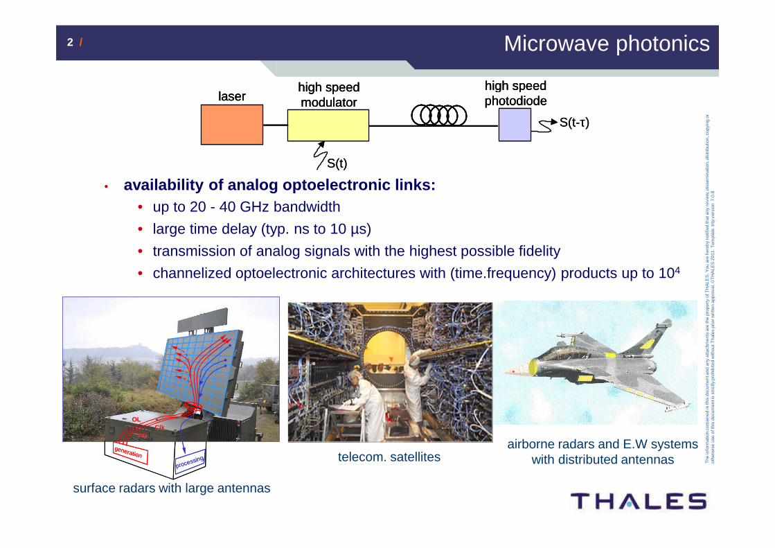
Microwave photonics
• availability of analog optoelectronic links:• up to 20 - 40 GHz bandwidth
• large time delay (typ. ns to 10 µs)
• transmission of analog signals with the highest possible fidelity
• channelized optoelectronic architectures with (time.frequency) products up to 104
generation
OLOL
processing
FOFOClkClk
generation
OLOL
processing
FOFOClkClk
surface radars with large antennas
airborne radars and E.W systems with distributed antennas
laserhigh speed modulator
high speed photodiode
S(t)
S(t-τ)
laserhigh speed modulator
high speed photodiodelaser
high speed modulator
high speed photodiode
S(t)
S(t-τ)
telecom. satellites
3 /3 /
The
info
rmat
ion
cont
aine
d in
this
doc
umen
t and
any
atta
chm
ents
are
the
prop
erty
of T
HA
LES
. You
are
her
eby
notif
ied
that
any
rev
iew
, dis
sem
inat
ion,
dis
trib
utio
n, c
opyi
ng o
r ot
herw
ise
use
of th
is d
ocum
ent i
s st
rictly
pro
hibi
ted
with
out T
hale
s pr
ior w
ritte
n ap
prov
al. ©
TH
ALE
S 2
011.
Tem
plat
e tr
tp v
ersi
on 7
.0.8
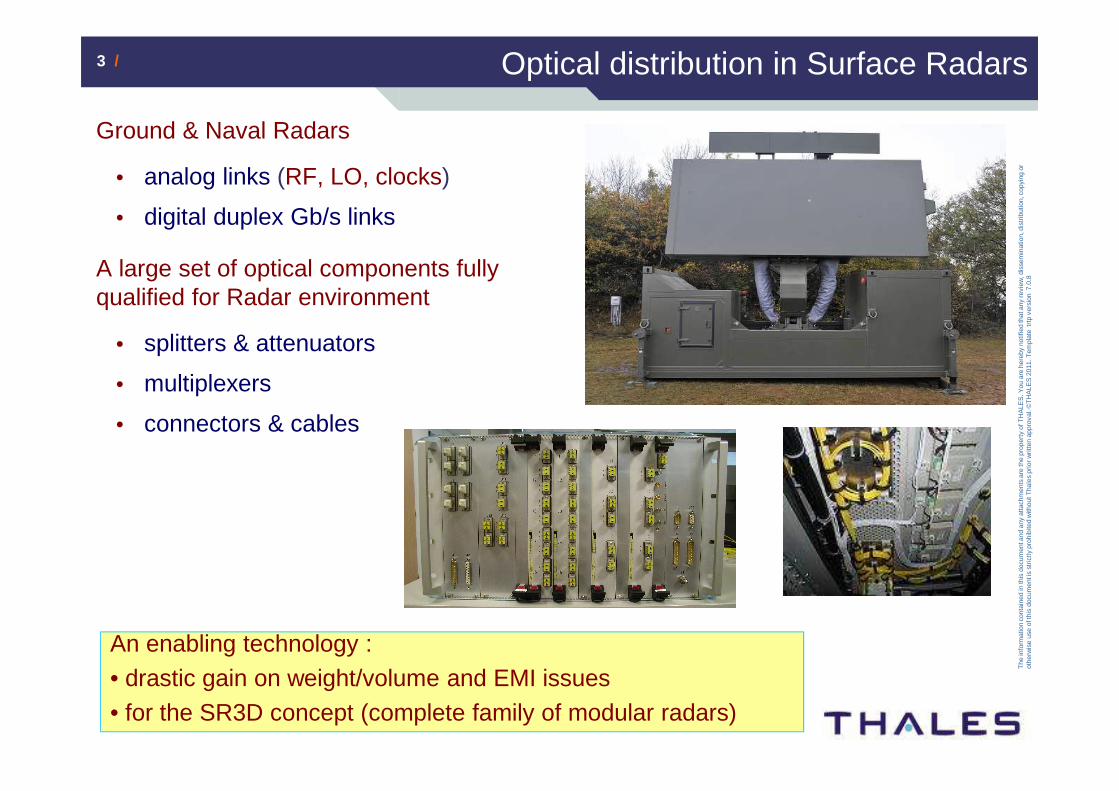
Optical distribution in Surface Radars
Ground & Naval Radars
• analog links (RF, LO, clocks)
• digital duplex Gb/s links
A large set of optical components fully qualified for Radar environment
• splitters & attenuators
• multiplexers
• connectors & cables
An enabling technology :• drastic gain on weight/volume and EMI issues • for the SR3D concept (complete family of modular radars)
4 /4 /
The
info
rmat
ion
cont
aine
d in
this
doc
umen
t and
any
atta
chm
ents
are
the
prop
erty
of T
HA
LES
. You
are
her
eby
notif
ied
that
any
rev
iew
, dis
sem
inat
ion,
dis
trib
utio
n, c
opyi
ng o
r ot
herw
ise
use
of th
is d
ocum
ent i
s st
rictly
pro
hibi
ted
with
out T
hale
s pr
ior w
ritte
n ap
prov
al. ©
TH
ALE
S 2
011.
Tem
plat
e tr
tp v
ersi
on 7
.0.8
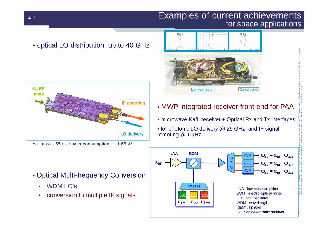
Examples of current achievementsfor space applications
• optical LO distribution up to 40 GHz
• Optical Multi-frequency Conversion
• WDM LO’s • conversion to multiple IF signals
20 GHz20 GHz 30 GHz 40 GHz20 GHz20 GHz 30 GHz 40 GHz
Microwave input Optical outputMicrowave input Optical output
LNA : low-noise amplifierEOM : electro-optical mixerLO : local oscillatorWDM : wavelength(de)multiplexerO/E : optoelectronic receiver
O/EO/ELNA
LO3LO1 LO2
ωIF1 = ωRF – ωLO1
ωRF
ωLO1
O/EO/E
O/EO/E
ωIF2 = ωRF – ωLO2
ωIF3 = ωRF – ωLO3
EOM
ωLO2 ωLO3
W D M
WDM
LNA : low-noise amplifierEOM : electro-optical mixerLO : local oscillatorWDM : wavelength(de)multiplexerO/E : optoelectronic receiver
O/EO/ELNA
LO3LO1 LO2
ωIF1 = ωRF – ωLO1
ωRF
ωLO1
O/EO/E
O/EO/E
ωIF2 = ωRF – ωLO2
ωIF3 = ωRF – ωLO3
EOM
ωLO2 ωLO3
W D M
WDM
IF remoting
LO delivery
Ka RFInput
IF remoting
LO delivery
Ka RFInput
• MWP integrated receiver front-end for PAA
• microwave Ka/L receiver + Optical Rx and Tx interfaces
• for photonic LO delivery @ 29 GHz and IF signal remoting @ 1GHz
est. mass : 55 g - power consumption : ~ 1.65 W
5 /5 /
The
info
rmat
ion
cont
aine
d in
this
doc
umen
t and
any
atta
chm
ents
are
the
prop
erty
of T
HA
LES
. You
are
her
eby
notif
ied
that
any
rev
iew
, dis
sem
inat
ion,
dis
trib
utio
n, c
opyi
ng o
r ot
herw
ise
use
of th
is d
ocum
ent i
s st
rictly
pro
hibi
ted
with
out T
hale
s pr
ior w
ritte
n ap
prov
al. ©
TH
ALE
S 2
011.
Tem
plat
e tr
tp v
ersi
on 7
.0.8
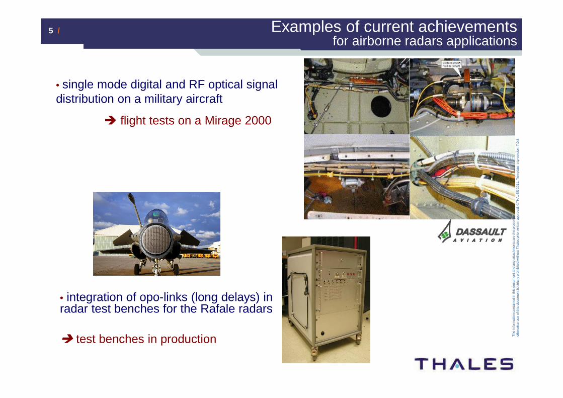
Examples of current achievementsfor airborne radars applications
• single mode digital and RF optical signal distribution on a military aircraft
� flight tests on a Mirage 2000
• integration of opo-links (long delays) in radar test benches for the Rafale radars
� test benches in production

6 /6 /
The
info
rmat
ion
cont
aine
d in
this
doc
umen
t and
any
atta
chm
ents
are
the
prop
erty
of T
HA
LES
. You
are
her
eby
notif
ied
that
any
rev
iew
, dis
sem
inat
ion,
dis
trib
utio
n, c
opyi
ng o
r ot
herw
ise
use
of th
is d
ocum
ent i
s st
rictly
pro
hibi
ted
with
out T
hale
s pr
ior w
ritte
n ap
prov
al. ©
TH
ALE
S 2
011.
Tem
plat
e tr
tp v
ersi
on 7
.0.8
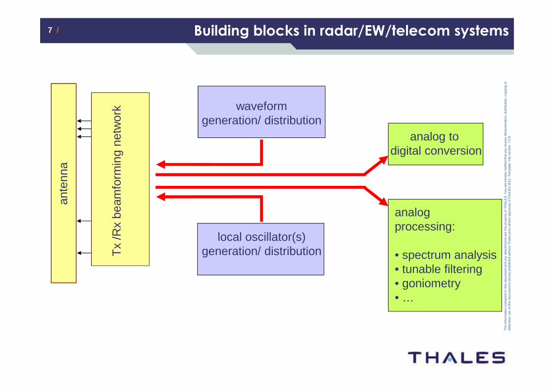
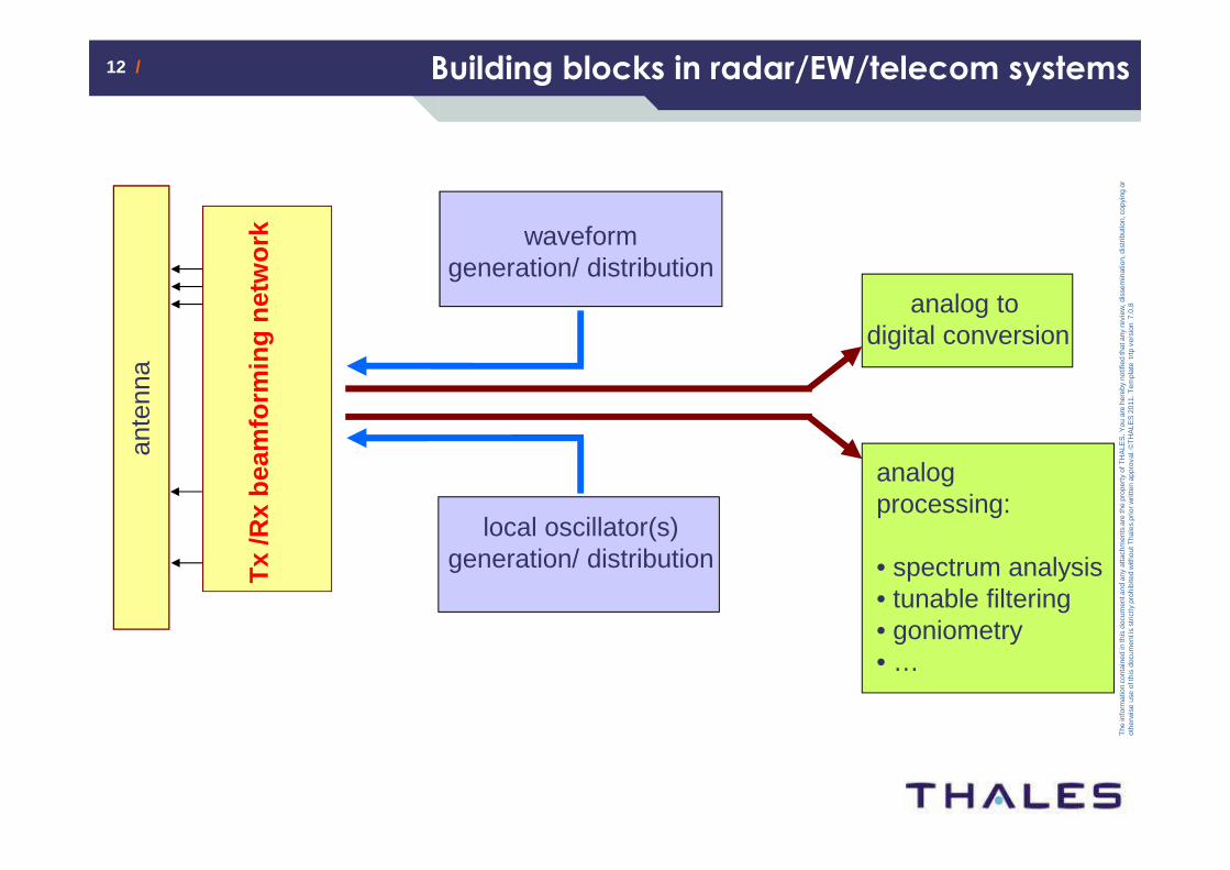
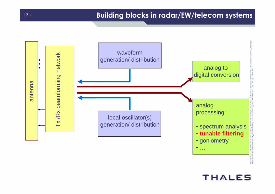
Building blocks in radar/EW/telecom systems
ante
nna
Tx
/Rx
beam
form
ing
netw
ork waveform
generation/ distribution
local oscillator(s) generation/ distribution
analog to digital conversion
analog processing:
• spectrum analysis• tunable filtering• goniometry• …
7 /7 /
The
info
rmat
ion
cont
aine
d in
this
doc
umen
t and
any
atta
chm
ents
are
the
prop
erty
of T
HA
LES
. You
are
her
eby
notif
ied
that
any
rev
iew
, dis
sem
inat
ion,
dis
trib
utio
n, c
opyi
ng o
r ot
herw
ise
use
of th
is d
ocum
ent i
s st
rictly
pro
hibi
ted
with
out T
hale
s pr
ior w
ritte
n ap
prov
al. ©
TH
ALE
S 2
011.
Tem
plat
e tr
tp v
ersi
on 7
.0.8
Building blocks in radar/EW/telecom systems
ante
nna
Tx
/Rx
beam
form
ing
netw
ork waveform
generation/ distribution
local oscillator(s) generation/ distribution
analog to digital conversion
analog processing:
• spectrum analysis• tunable filtering• goniometry• …

8 /8 /
The
info
rmat
ion
cont
aine
d in
this
doc
umen
t and
any
atta
chm
ents
are
the
prop
erty
of T
HA
LES
. You
are
her
eby
notif
ied
that
any
rev
iew
, dis
sem
inat
ion,
dis
trib
utio
n, c
opyi
ng o
r ot
herw
ise
use
of th
is d
ocum
ent i
s st
rictly
pro
hibi
ted
with
out T
hale
s pr
ior w
ritte
n ap
prov
al. ©
TH
ALE
S 2
011.
Tem
plat
e tr
tp v
ersi
on 7
.0.8
DFB laser diode:� class-B laser where
τphotons< τelectrons
� resonant noise spectrum
Influence of laser RIN
potential solutions :
• class-A semiconductor laser with τp >> τe
• solid state diode pumped Er lasers• RIN filtering through non-linear optics
Radar Antenna
RF Signal
Typical RFOptical
LinkDFB MZ Signal
Processing
Radar Antenna
RF Signal
Radar Antenna
RF Signal
Typical RFOptical
LinkDFB MZDFB MZ Signal
ProcessingSignal
Processing
RF
Pow
er(d
Bm
/Hz)
80.1GHz 18GHz
Noise Floor
RF Signal
RF
Pow
er(d
Bm
/Hz)
80.1GHz 18GHz
Noise Floor
RF Signal
�
20
20
20
2 )()()()(
i
fS
P
fS
P
fPfRIN ip ==⟩∆⟨=
laser fluctuations
laser mean power
9 /9 /
The
info
rmat
ion
cont
aine
d in
this
doc
umen
t and
any
atta
chm
ents
are
the
prop
erty
of T
HA
LES
. You
are
her
eby
notif
ied
that
any
rev
iew
, dis
sem
inat
ion,
dis
trib
utio
n, c
opyi
ng o
r ot
herw
ise
use
of th
is d
ocum
ent i
s st
rictly
pro
hibi
ted
with
out T
hale
s pr
ior w
ritte
n ap
prov
al. ©
TH
ALE
S 2
011.
Tem
plat
e tr
tp v
ersi
on 7
.0.8
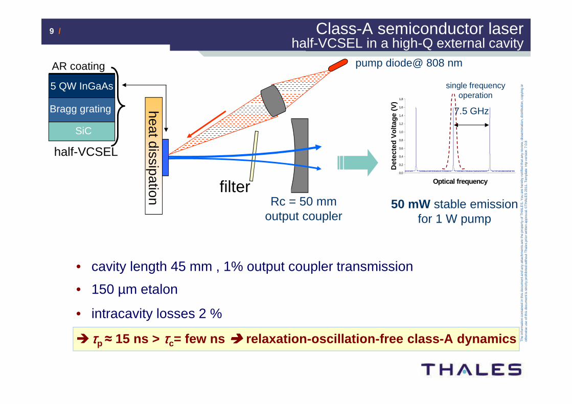
SiC
AR coating
5 QW InGaAs
Bragg grating
half-VCSEL
• cavity length 45 mm , 1% output coupler transmission
• 150 µm etalon
• intracavity losses 2 %
� ττττp ≈ 15 ns > ττττc= few ns ���� relaxation-oscillation-free class-A dynamics
50 mW stable emission for 1 W pump
0,0
0,2
0,4
0,6
0,8
1,0
1,2
1,4
1,6
1,8
Optical frequency
Det
ecte
d V
olta
ge (
V)
7.5 GHz
filter
heat dissipation
pump diode@ 808 nm
Rc = 50 mm output coupler
Class-A semiconductor laser half-VCSEL in a high-Q external cavity
single frequency operation
10 /10 /
The
info
rmat
ion
cont
aine
d in
this
doc
umen
t and
any
atta
chm
ents
are
the
prop
erty
of T
HA
LES
. You
are
her
eby
notif
ied
that
any
rev
iew
, dis
sem
inat
ion,
dis
trib
utio
n, c
opyi
ng o
r ot
herw
ise
use
of th
is d
ocum
ent i
s st
rictly
pro
hibi
ted
with
out T
hale
s pr
ior w
ritte
n ap
prov
al. ©
TH
ALE
S 2
011.
Tem
plat
e tr
tp v
ersi
on 7
.0.8
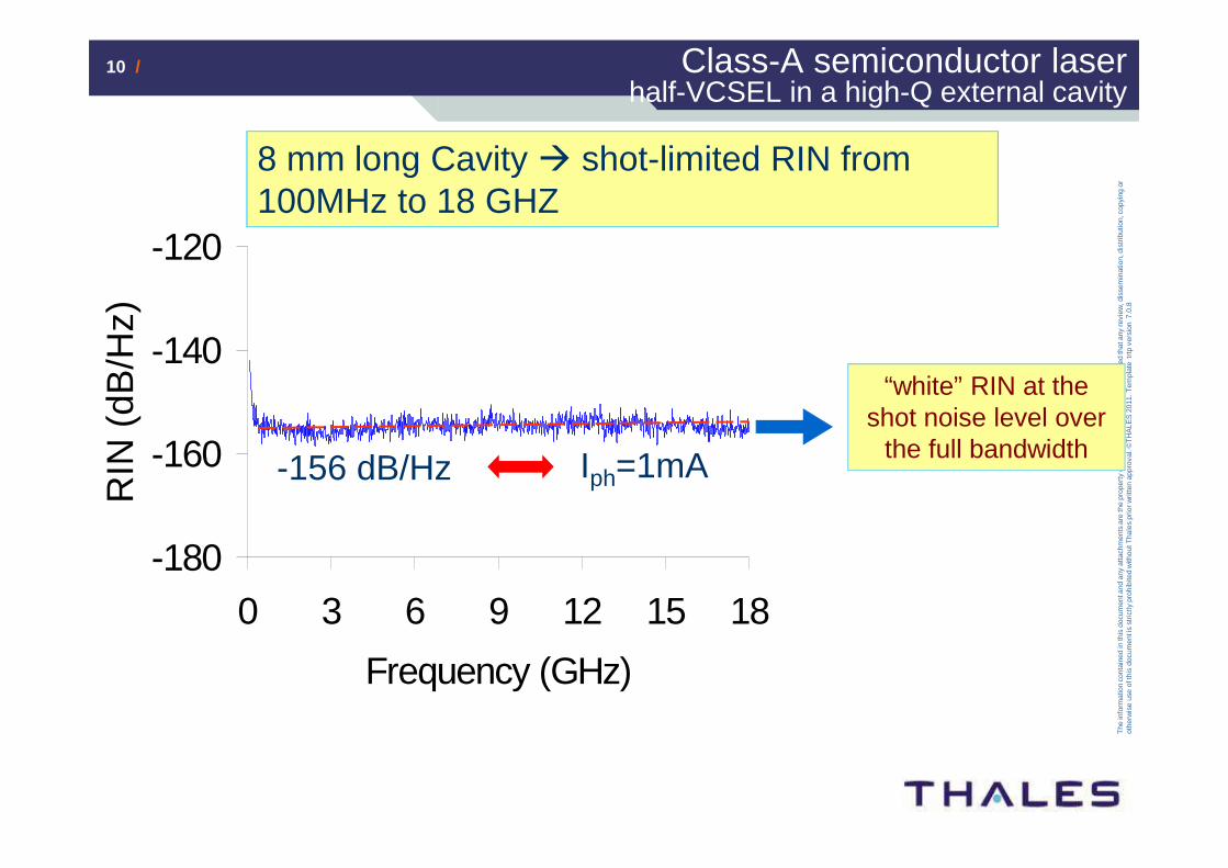
-180
-160
-140
-120
0 3 6 9 12 15 18
Frequency (GHz)
RIN
(dB
/Hz)
-156 dB/Hz Iph=1mA
8 mm long Cavity � shot-limited RIN from 100MHz to 18 GHZ
“white” RIN at the shot noise level over
the full bandwidth
Class-A semiconductor laser half-VCSEL in a high-Q external cavity
11 /11 /
The
info
rmat
ion
cont
aine
d in
this
doc
umen
t and
any
atta
chm
ents
are
the
prop
erty
of T
HA
LES
. You
are
her
eby
notif
ied
that
any
rev
iew
, dis
sem
inat
ion,
dis
trib
utio
n, c
opyi
ng o
r ot
herw
ise
use
of th
is d
ocum
ent i
s st
rictly
pro
hibi
ted
with
out T
hale
s pr
ior w
ritte
n ap
prov
al. ©
TH
ALE
S 2
011.
Tem
plat
e tr
tp v
ersi
on 7
.0.8
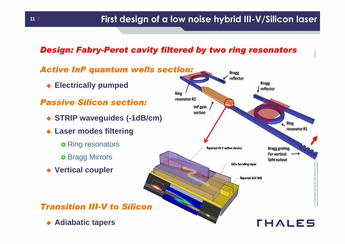
First design of a low noise hybrid III-V/Silicon laser
Design: Fabry-Perot cavity filtered by two ring resonators
Active InP quantum wells section:
� Electrically pumped
Passive Silicon section:
� STRIP waveguides (-1dB/cm)
� Laser modes filtering
� Ring resonators
� Bragg Mirrors
� Vertical coupler
Transition III-V to Silicon
� Adiabatic tapers
12 /12 /
The
info
rmat
ion
cont
aine
d in
this
doc
umen
t and
any
atta
chm
ents
are
the
prop
erty
of T
HA
LES
. You
are
her
eby
notif
ied
that
any
rev
iew
, dis
sem
inat
ion,
dis
trib
utio
n, c
opyi
ng o
r ot
herw
ise
use
of th
is d
ocum
ent i
s st
rictly
pro
hibi
ted
with
out T
hale
s pr
ior w
ritte
n ap
prov
al. ©
TH
ALE
S 2
011.
Tem
plat
e tr
tp v
ersi
on 7
.0.8
Building blocks in radar/EW/telecom systems
ante
nna
Tx
/Rx
beam
form
ing
netw
ork waveform
generation/ distribution
local oscillator(s) generation/ distribution
analog to digital conversion
analog processing:
• spectrum analysis• tunable filtering• goniometry• …
13 /13 /
The
info
rmat
ion
cont
aine
d in
this
doc
umen
t and
any
atta
chm
ents
are
the
prop
erty
of T
HA
LES
. You
are
her
eby
notif
ied
that
any
rev
iew
, dis
sem
inat
ion,
dis
trib
utio
n, c
opyi
ng o
r ot
herw
ise
use
of th
is d
ocum
ent i
s st
rictly
pro
hibi
ted
with
out T
hale
s pr
ior w
ritte
n ap
prov
al. ©
TH
ALE
S 2
011.
Tem
plat
e tr
tp v
ersi
on 7
.0.8
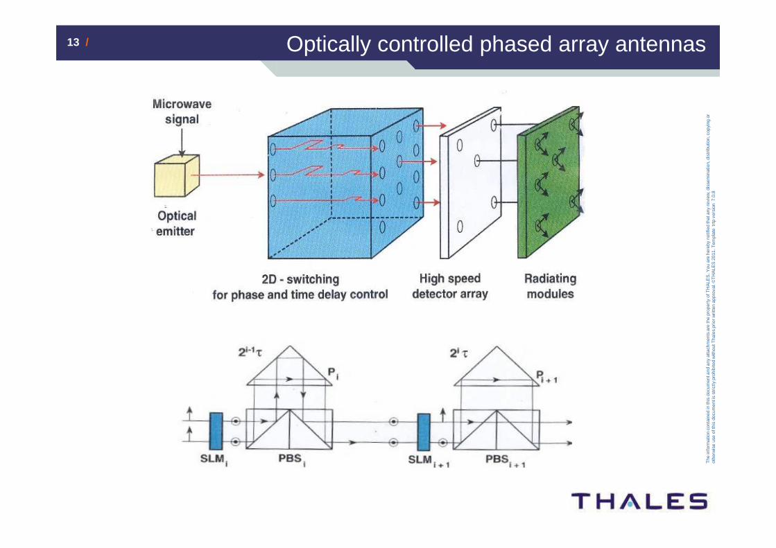
Optically controlled phased array antennas
Transmit mode
14 /14 /
The
info
rmat
ion
cont
aine
d in
this
doc
umen
t and
any
atta
chm
ents
are
the
prop
erty
of T
HA
LES
. You
are
her
eby
notif
ied
that
any
rev
iew
, dis
sem
inat
ion,
dis
trib
utio
n, c
opyi
ng o
r ot
herw
ise
use
of th
is d
ocum
ent i
s st
rictly
pro
hibi
ted
with
out T
hale
s pr
ior w
ritte
n ap
prov
al. ©
TH
ALE
S 2
011.
Tem
plat
e tr
tp v
ersi
on 7
.0.8
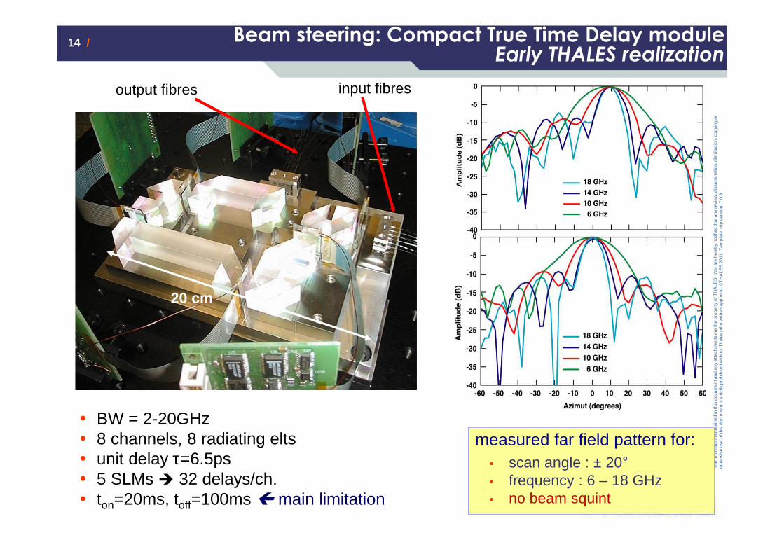
Beam steering: Compact True Time Delay moduleEarly THALES realization
input fibresoutput fibres
� BW = 2-20GHz� 8 channels, 8 radiating elts� unit delay τ=6.5ps� 5 SLMs � 32 delays/ch.� ton=20ms, toff=100ms main limitation
20 cm
measured far field pattern for:� scan angle : ± 20°� frequency : 6 – 18 GHz� no beam squint
15 /15 /
The
info
rmat
ion
cont
aine
d in
this
doc
umen
t and
any
atta
chm
ents
are
the
prop
erty
of T
HA
LES
. You
are
her
eby
notif
ied
that
any
rev
iew
, dis
sem
inat
ion,
dis
trib
utio
n, c
opyi
ng o
r ot
herw
ise
use
of th
is d
ocum
ent i
s st
rictly
pro
hibi
ted
with
out T
hale
s pr
ior w
ritte
n ap
prov
al. ©
TH
ALE
S 2
011.
Tem
plat
e tr
tp v
ersi
on 7
.0.8
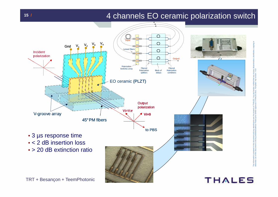
4 channels EO ceramic polarization switch
EO ceramic (PLZT)
V-groove array
Gnd V1V2
V3V4
Incident polarization
Output polarization
Vi=0Vi=Vππππ
to PBS
45°PM fibers
EO ceramic (PLZT)
V-groove array
Gnd V1V2
V3V4
Incident polarization
Output polarization
Vi=0Vi=Vππππ
to PBS
45°PM fibers
• 3 µs response time• < 2 dB insertion loss• > 20 dB extinction ratio
Input
Polarization
Switches array Fibered Polarization splitters
Fibered Polarization combiners
Output
Block of delays
Lensed fibers
TRT + Besançon + TeemPhotonic
16 /16 /
The
info
rmat
ion
cont
aine
d in
this
doc
umen
t and
any
atta
chm
ents
are
the
prop
erty
of T
HA
LES
. You
are
her
eby
notif
ied
that
any
rev
iew
, dis
sem
inat
ion,
dis
trib
utio
n, c
opyi
ng o
r ot
herw
ise
use
of th
is d
ocum
ent i
s st
rictly
pro
hibi
ted
with
out T
hale
s pr
ior w
ritte
n ap
prov
al. ©
TH
ALE
S 2
011.
Tem
plat
e tr
tp v
ersi
on 7
.0.8
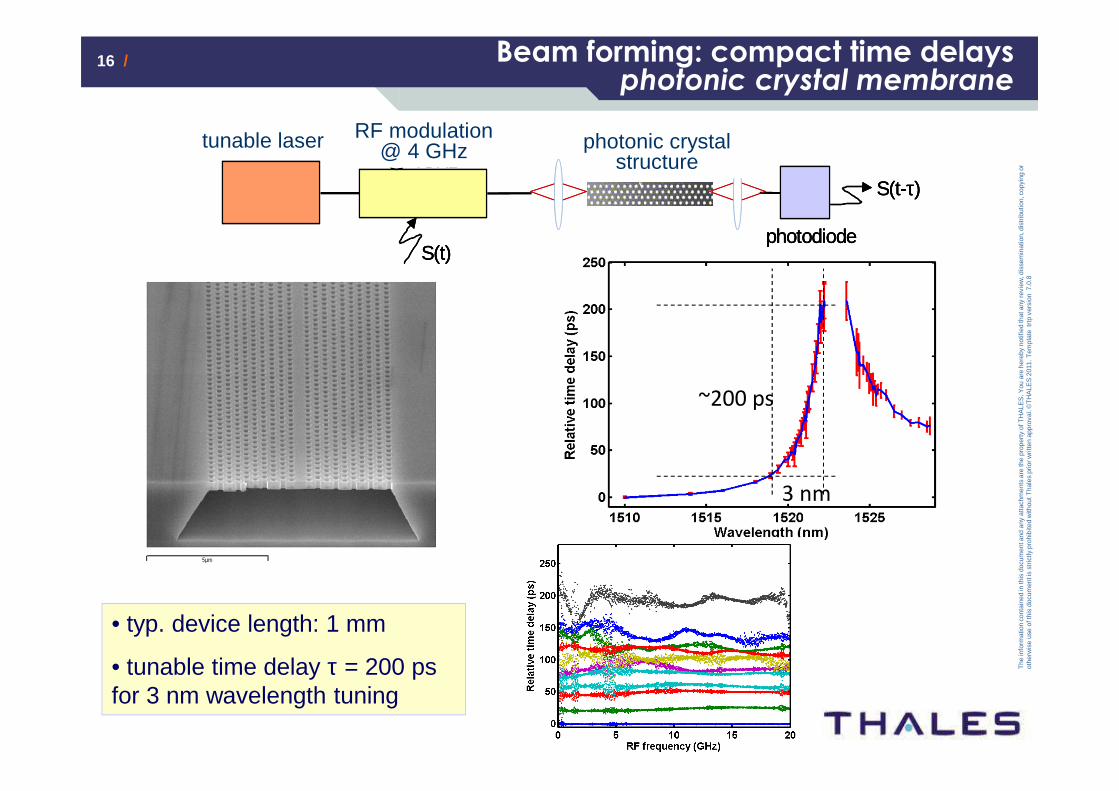
laser accordable modulateur RF
@ 4GHz
S(t)photodiode
S(t-τ)
struct. photoniquelaser accordable modulateur RF
@ 4GHz
S(t)
laser accordable modulateur RF
@ 4GHz
S(t)photodiode
S(t-τ)
photodiode
S(t-τ)
struct. photonique
• typ. device length: 1 mm
• tunable time delay τ = 200 ps for 3 nm wavelength tuning
tunable laser RF modulation @ 4 GHz photonic crystal
structure
Beam forming: compact time delaysphotonic crystal membrane
3 nm
~200 ps
17 /17 /
The
info
rmat
ion
cont
aine
d in
this
doc
umen
t and
any
atta
chm
ents
are
the
prop
erty
of T
HA
LES
. You
are
her
eby
notif
ied
that
any
rev
iew
, dis
sem
inat
ion,
dis
trib
utio
n, c
opyi
ng o
r ot
herw
ise
use
of th
is d
ocum
ent i
s st
rictly
pro
hibi
ted
with
out T
hale
s pr
ior w
ritte
n ap
prov
al. ©
TH
ALE
S 2
011.
Tem
plat
e tr
tp v
ersi
on 7
.0.8
Building blocks in radar/EW/telecom systems
ante
nna
Tx
/Rx
beam
form
ing
netw
ork waveform
generation/ distribution
local oscillator(s) generation/ distribution
analog to digital conversion
analog processing:
• spectrum analysis• tunable filtering• goniometry• …
18 /18 /
The
info
rmat
ion
cont
aine
d in
this
doc
umen
t and
any
atta
chm
ents
are
the
prop
erty
of T
HA
LES
. You
are
her
eby
notif
ied
that
any
rev
iew
, dis
sem
inat
ion,
dis
trib
utio
n, c
opyi
ng o
r ot
herw
ise
use
of th
is d
ocum
ent i
s st
rictly
pro
hibi
ted
with
out T
hale
s pr
ior w
ritte
n ap
prov
al. ©
TH
ALE
S 2
011.
Tem
plat
e tr
tp v
ersi
on 7
.0.8
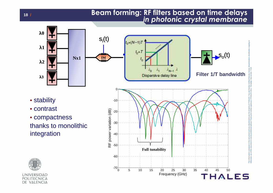
Nx1
si(t)
IM
λλλλ0
λλλλ1
λλλλ2
λλλλ3
Nx1
si(t)
IM
λλλλ0
λλλλ1
λλλλ2
λλλλ3
PhC
so(t)so(t)
Beam forming: RF filters based on time delaysin photonic crystal membrane
0 5 10 15 20 25 30 35 40 45 50-70
-60
-50
-40
-30
-20
-10
0
Frequency (GHz)
RF
pow
er v
aria
tion
(dB
)
Full tunability
• stability• contrast• compactnessthanks to monolithic integration
Filter 1/T bandwidth
19 /19 /
The
info
rmat
ion
cont
aine
d in
this
doc
umen
t and
any
atta
chm
ents
are
the
prop
erty
of T
HA
LES
. You
are
her
eby
notif
ied
that
any
rev
iew
, dis
sem
inat
ion,
dis
trib
utio
n, c
opyi
ng o
r ot
herw
ise
use
of th
is d
ocum
ent i
s st
rictly
pro
hibi
ted
with
out T
hale
s pr
ior w
ritte
n ap
prov
al. ©
TH
ALE
S 2
011.
Tem
plat
e tr
tp v
ersi
on 7
.0.8
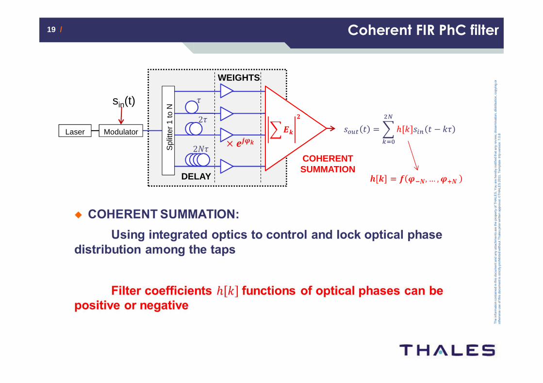
Coherent FIR PhC filter
Laser
Spl
itter
1 to
NDELAY
sin(t)
Modulator
WEIGHTS
COHERENT SUMMATION
20 /20 /
The
info
rmat
ion
cont
aine
d in
this
doc
umen
t and
any
atta
chm
ents
are
the
prop
erty
of T
HA
LES
. You
are
her
eby
notif
ied
that
any
rev
iew
, dis
sem
inat
ion,
dis
trib
utio
n, c
opyi
ng o
r ot
herw
ise
use
of th
is d
ocum
ent i
s st
rictly
pro
hibi
ted
with
out T
hale
s pr
ior w
ritte
n ap
prov
al. ©
TH
ALE
S 2
011.
Tem
plat
e tr
tp v
ersi
on 7
.0.8
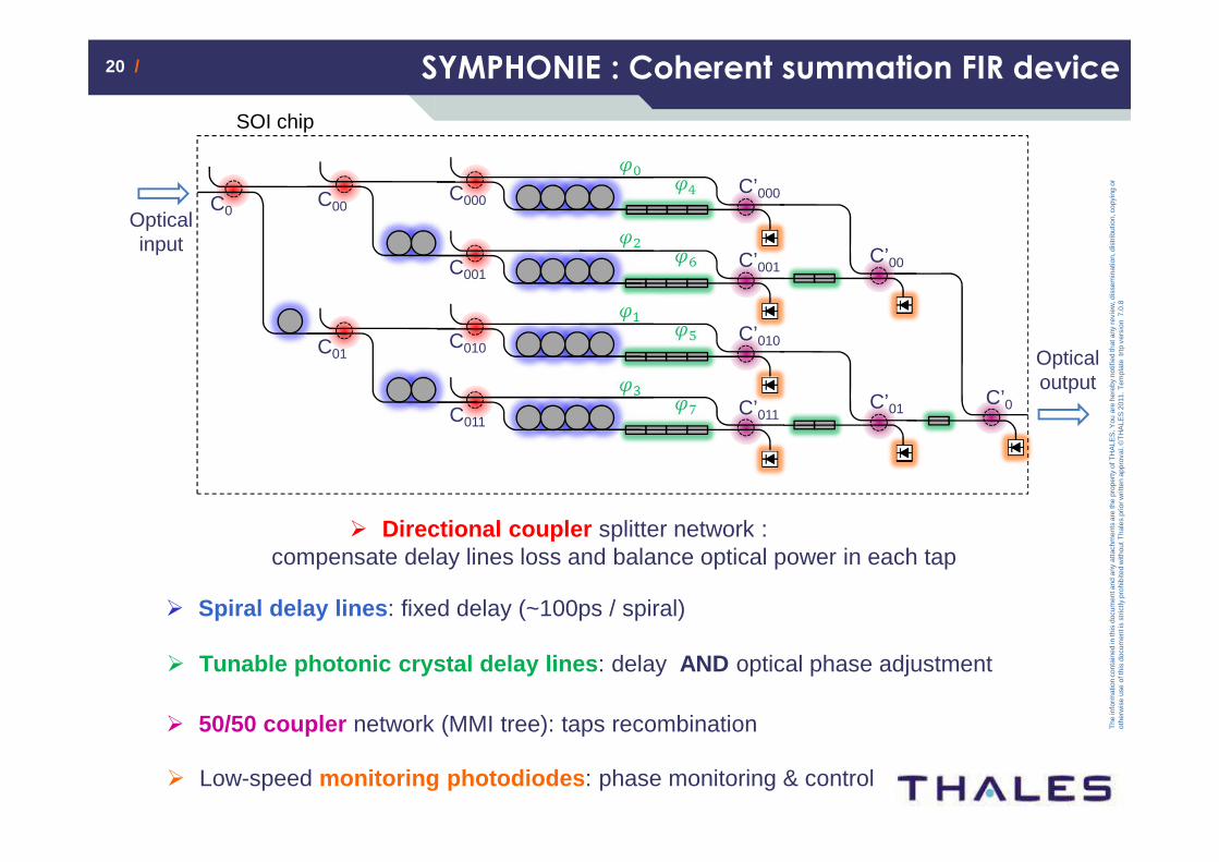
� Tunable photonic crystal delay lines : delay AND optical phase adjustment
� Low-speed monitoring photodiodes : phase monitoring & control
� 50/50 coupler network (MMI tree): taps recombination
� Directional coupler splitter network : compensate delay lines loss and balance optical power in each tap
� Spiral delay lines : fixed delay (~100ps / spiral)
SYMPHONIE : Coherent summation FIR device
C0
C’0
C00
C01
C000
C010
C001
C011
C’000
C’010
C’001
C’011
C’00
C’01
Optical input
Optical output
SOI chip
21 /21 /
The
info
rmat
ion
cont
aine
d in
this
doc
umen
t and
any
atta
chm
ents
are
the
prop
erty
of T
HA
LES
. You
are
her
eby
notif
ied
that
any
rev
iew
, dis
sem
inat
ion,
dis
trib
utio
n, c
opyi
ng o
r ot
herw
ise
use
of th
is d
ocum
ent i
s st
rictly
pro
hibi
ted
with
out T
hale
s pr
ior w
ritte
n ap
prov
al. ©
TH
ALE
S 2
011.
Tem
plat
e tr
tp v
ersi
on 7
.0.8
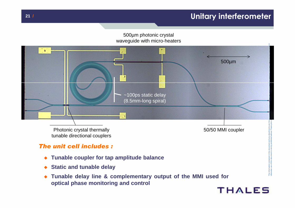
Unitary interferometer
The unit cell includes :
� Tunable coupler for tap amplitude balance
� Static and tunable delay
� Tunable delay line & complementary output of the MMI used foroptical phase monitoring and control
500µm
~100ps static delay(8.5mm-long spiral)
500µm photonic crystal waveguide with micro-heaters
Photonic crystal thermally tunable directional couplers
50/50 MMI coupler
22 /22 /
The
info
rmat
ion
cont
aine
d in
this
doc
umen
t and
any
atta
chm
ents
are
the
prop
erty
of T
HA
LES
. You
are
her
eby
notif
ied
that
any
rev
iew
, dis
sem
inat
ion,
dis
trib
utio
n, c
opyi
ng o
r ot
herw
ise
use
of th
is d
ocum
ent i
s st
rictly
pro
hibi
ted
with
out T
hale
s pr
ior w
ritte
n ap
prov
al. ©
TH
ALE
S 2
011.
Tem
plat
e tr
tp v
ersi
on 7
.0.8
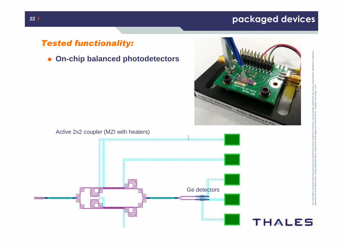
packaged devices
Ge detectors
Active 2x2 coupler (MZI with heaters)
Tested functionality:
� On-chip balanced photodetectors

23 /23 /
The
info
rmat
ion
cont
aine
d in
this
doc
umen
t and
any
atta
chm
ents
are
the
prop
erty
of T
HA
LES
. You
are
her
eby
notif
ied
that
any
rev
iew
, dis
sem
inat
ion,
dis
trib
utio
n, c
opyi
ng o
r ot
herw
ise
use
of th
is d
ocum
ent i
s st
rictly
pro
hibi
ted
with
out T
hale
s pr
ior w
ritte
n ap
prov
al. ©
TH
ALE
S 2
011.
Tem
plat
e tr
tp v
ersi
on 7
.0.8
Building blocks in radar/EW/telecom systems
ante
nna
Tx
/Rx
beam
form
ing
netw
ork waveform
generation/ distribution
local oscillator(s) generation
analog to digital conversion
analog processing:
• spectrum analysis• tunable filtering• goniometry• …
24 /24 /
The
info
rmat
ion
cont
aine
d in
this
doc
umen
t and
any
atta
chm
ents
are
the
prop
erty
of T
HA
LES
. You
are
her
eby
notif
ied
that
any
rev
iew
, dis
sem
inat
ion,
dis
trib
utio
n, c
opyi
ng o
r ot
herw
ise
use
of th
is d
ocum
ent i
s st
rictly
pro
hibi
ted
with
out T
hale
s pr
ior w
ritte
n ap
prov
al. ©
TH
ALE
S 2
011.
Tem
plat
e tr
tp v
ersi
on 7
.0.8
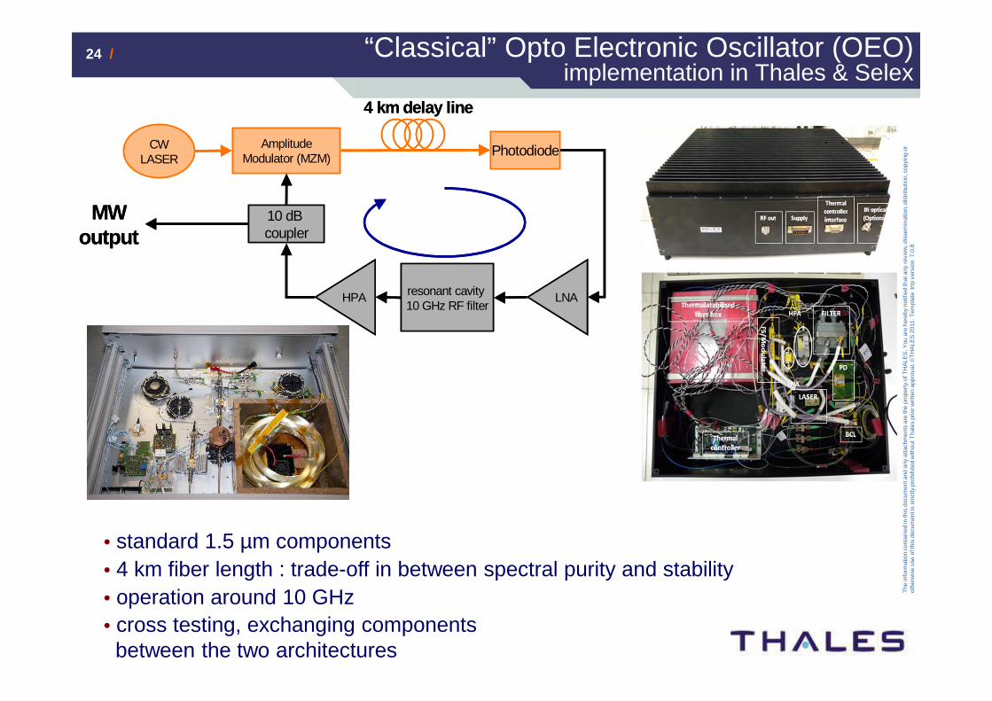
• standard 1.5 µm components• 4 km fiber length : trade-off in between spectral purity and stability• operation around 10 GHz• cross testing, exchanging components between the two architectures
“Classical” Opto Electronic Oscillator (OEO) implementation in Thales & Selex
CW LASER
Amplitude Modulator (MZM)
Photodiode
resonant cavity 10 GHz RF filter
10 dB coupler
LNAHPA
MWoutput
4 km delay line
CW LASER
Amplitude Modulator (MZM)
Photodiode
resonant cavity 10 GHz RF filter
10 dB coupler
LNAHPA
MWoutput
4 km delay line
25 /25 /
The
info
rmat
ion
cont
aine
d in
this
doc
umen
t and
any
atta
chm
ents
are
the
prop
erty
of T
HA
LES
. You
are
her
eby
notif
ied
that
any
rev
iew
, dis
sem
inat
ion,
dis
trib
utio
n, c
opyi
ng o
r ot
herw
ise
use
of th
is d
ocum
ent i
s st
rictly
pro
hibi
ted
with
out T
hale
s pr
ior w
ritte
n ap
prov
al. ©
TH
ALE
S 2
011.
Tem
plat
e tr
tp v
ersi
on 7
.0.8
102 103 104 105 106 107 108-180
-170
-160
-150
-140
-130
-120
-110
-100
-90
-80
-70
-60
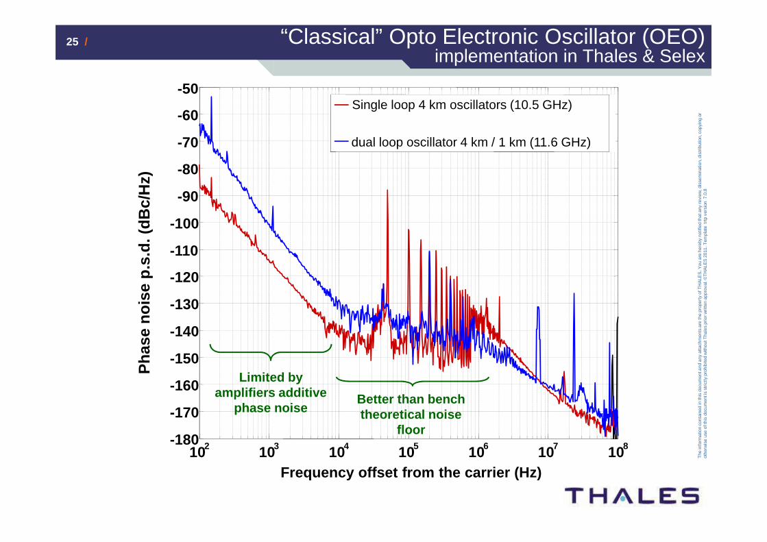
-50Single loop 4 km oscillators (10.5 GHz)
dual loop oscillator 4 km / 1 km (11.6 GHz)P
hase
noi
se p
.s.d
. (dB
c/H
z)
Frequency offset from the carrier (Hz)
Limited by amplifiers additive
phase noiseBetter than bench theoretical noise
floor
“Classical” Opto Electronic Oscillator (OEO) implementation in Thales & Selex
26 /26 /
The
info
rmat
ion
cont
aine
d in
this
doc
umen
t and
any
atta
chm
ents
are
the
prop
erty
of T
HA
LES
. You
are
her
eby
notif
ied
that
any
rev
iew
, dis
sem
inat
ion,
dis
trib
utio
n, c
opyi
ng o
r ot
herw
ise
use
of th
is d
ocum
ent i
s st
rictly
pro
hibi
ted
with
out T
hale
s pr
ior w
ritte
n ap
prov
al. ©
TH
ALE
S 2
011.
Tem
plat
e tr
tp v
ersi
on 7
.0.8
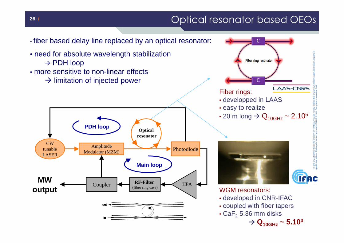
Optical resonator based OEOs
Fiber rings: • developped in LAAS• easy to realize• 20 m long � Q10GHz ~ 2.105
WGM resonators:• developed in CNR-IFAC• coupled with fiber tapers• CaF2 5.36 mm disks
���� Q10GHz ~ 5.103
CW tunable LASER
Amplitude Modulator (MZM) Photodiode
Coupler HPAMW
output
Main loop
PDH loop
RF-Filter(fiber ring case)
Optical resonator
• fiber based delay line replaced by an optical resonator:
• need for absolute wavelength stabilization � PDH loop
• more sensitive to non-linear effects � limitation of injected power
27 /27 /
The
info
rmat
ion
cont
aine
d in
this
doc
umen
t and
any
atta
chm
ents
are
the
prop
erty
of T
HA
LES
. You
are
her
eby
notif
ied
that
any
rev
iew
, dis
sem
inat
ion,
dis
trib
utio
n, c
opyi
ng o
r ot
herw
ise
use
of th
is d
ocum
ent i
s st
rictly
pro
hibi
ted
with
out T
hale
s pr
ior w
ritte
n ap
prov
al. ©
TH
ALE
S 2
011.
Tem
plat
e tr
tp v
ersi
on 7
.0.8
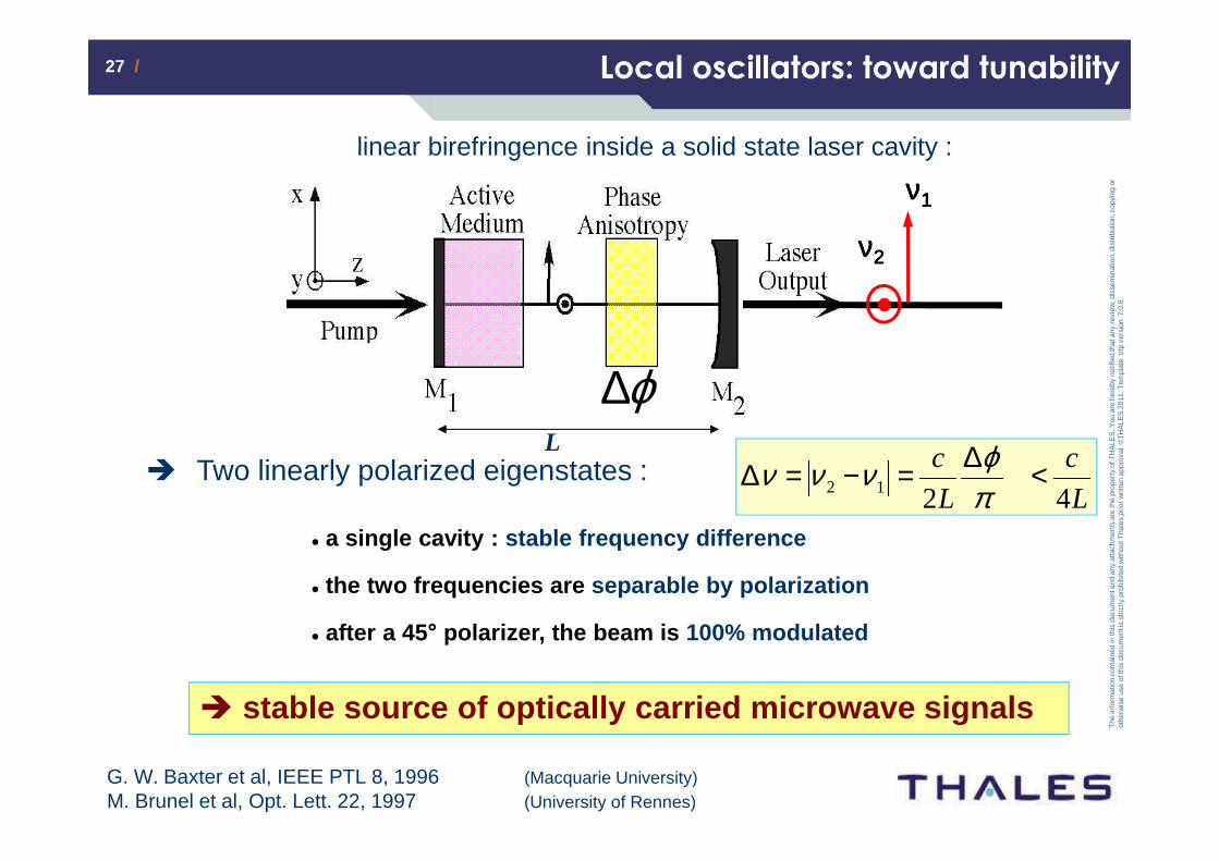
Local oscillators: toward tunability
linear birefringence inside a solid state laser cavity :
L
c
L
c
4212 <∆=−=∆πϕννν� Two linearly polarized eigenstates :
� stable source of optically carried microwave signal s
ϕ∆
νννν1111
νννν2222
L
G. W. Baxter et al, IEEE PTL 8, 1996 (Macquarie University)M. Brunel et al, Opt. Lett. 22, 1997 (University of Rennes)
� a single cavity : stable frequency difference
� the two frequencies are separable by polarization
� after a 45 ° polarizer, the beam is 100% modulated
28 /28 /
The
info
rmat
ion
cont
aine
d in
this
doc
umen
t and
any
atta
chm
ents
are
the
prop
erty
of T
HA
LES
. You
are
her
eby
notif
ied
that
any
rev
iew
, dis
sem
inat
ion,
dis
trib
utio
n, c
opyi
ng o
r ot
herw
ise
use
of th
is d
ocum
ent i
s st
rictly
pro
hibi
ted
with
out T
hale
s pr
ior w
ritte
n ap
prov
al. ©
TH
ALE
S 2
011.
Tem
plat
e tr
tp v
ersi
on 7
.0.8
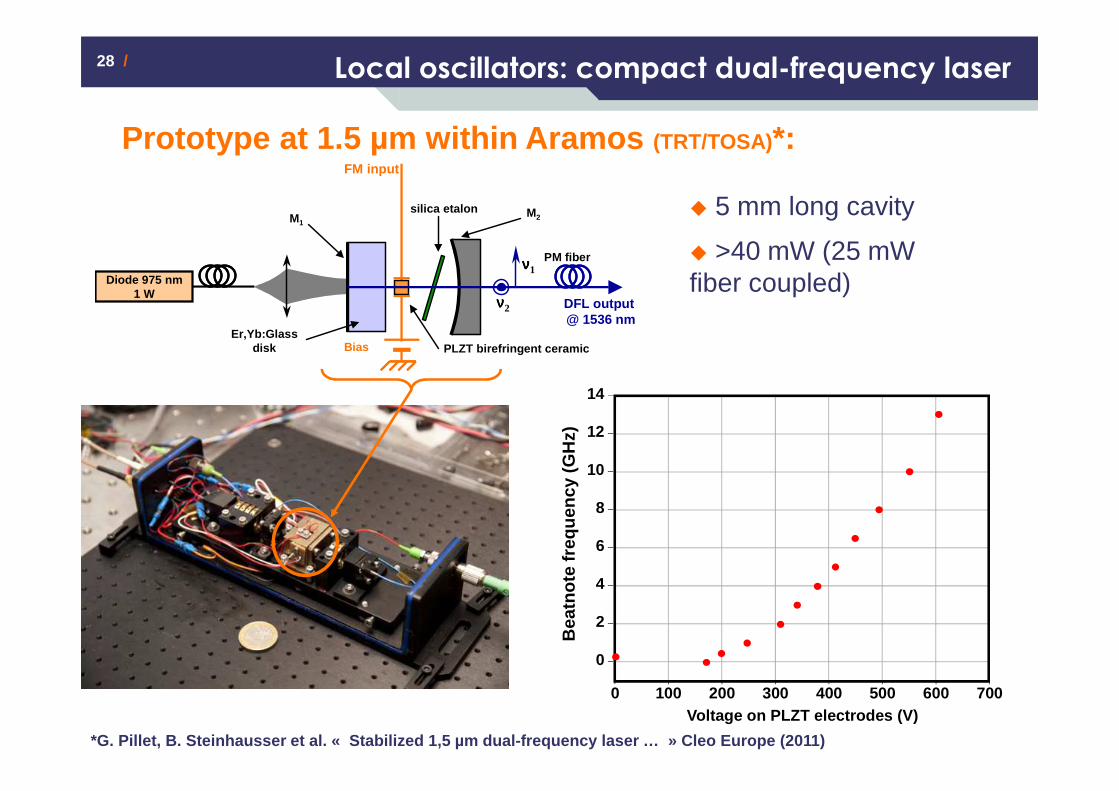
Local oscillators: compact dual-frequency laser
*G. Pillet, B. Steinhausser et al. « Stabilized 1,5 µ m dual-frequency laser … » Cleo Europe (2011)
PLZT birefringent ceramicEr,Yb:Glass
disk
νννν1
νννν2
M2M1
Diode 975 nm 1 W
silica etalon
Bias
FM input
DFL output @ 1536 nm
PM fiber
� 5 mm long cavity
� >40 mW (25 mW fiber coupled)
Prototype at 1.5 µm within Aramos (TRT/TOSA)*:
Bea
tnot
efr
eque
ncy
(GH
z)
Voltage on PLZT electrodes (V)0 300 400 700600500200100
12
8
6
4
2
0
10
14
29 /29 /
The
info
rmat
ion
cont
aine
d in
this
doc
umen
t and
any
atta
chm
ents
are
the
prop
erty
of T
HA
LES
. You
are
her
eby
notif
ied
that
any
rev
iew
, dis
sem
inat
ion,
dis
trib
utio
n, c
opyi
ng o
r ot
herw
ise
use
of th
is d
ocum
ent i
s st
rictly
pro
hibi
ted
with
out T
hale
s pr
ior w
ritte
n ap
prov
al. ©
TH
ALE
S 2
011.
Tem
plat
e tr
tp v
ersi
on 7
.0.8
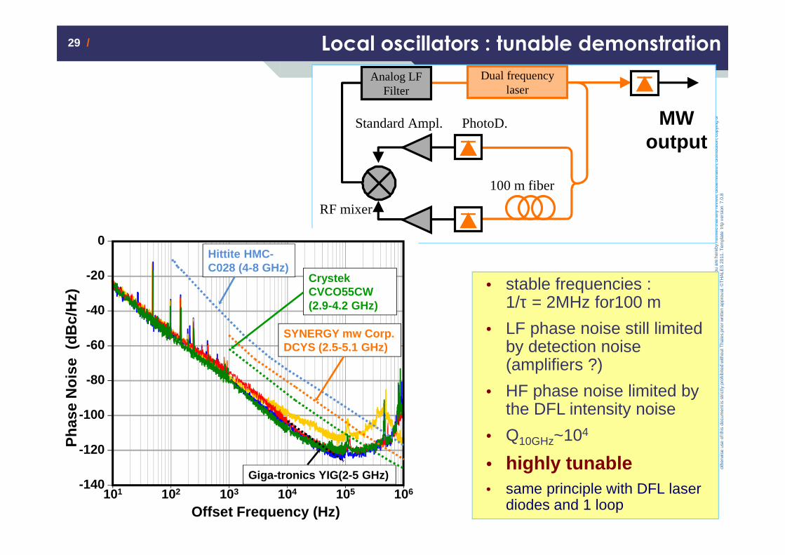
• stable frequencies : 1/τ = 2MHz for100 m
• LF phase noise still limited by detection noise (amplifiers ?)
• HF phase noise limited by the DFL intensity noise
• Q10GHz~104
• highly tunable• same principle with DFL laser
diodes and 1 loop
Dual frequency laser
Analog LFFilter
MWoutput
100 m fiber
Standard Ampl. PhotoD.
RF mixer
Local oscillators : tunable demonstration
0
-20
-40
-60
-80
-100
-120Pha
se N
oise
(dB
c/H
z)
-140101 102 103 104 105 106
Offset Frequency (Hz)
2.5 GHz
3.5 GHz
4.5 GHz
5.5 GHz
0
-20
-40
-60
-80
-100
-120Pha
se N
oise
(dB
c/H
z)
-140101 102 103 104 105 106
Offset Frequency (Hz)
Hittite HMC-C028 (4-8 GHz)
Crystek CVCO55CW (2.9-4.2 GHz)
SYNERGY mw Corp. DCYS (2.5-5.1 GHz)
Giga-tronics YIG(2-5 GHz)
30 /30 /
The
info
rmat
ion
cont
aine
d in
this
doc
umen
t and
any
atta
chm
ents
are
the
prop
erty
of T
HA
LES
. You
are
her
eby
notif
ied
that
any
rev
iew
, dis
sem
inat
ion,
dis
trib
utio
n, c
opyi
ng o
r ot
herw
ise
use
of th
is d
ocum
ent i
s st
rictly
pro
hibi
ted
with
out T
hale
s pr
ior w
ritte
n ap
prov
al. ©
TH
ALE
S 2
011.
Tem
plat
e tr
tp v
ersi
on 7
.0.8
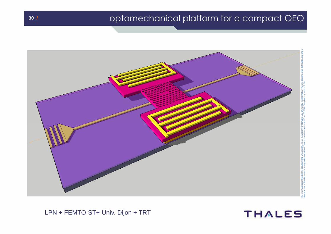
optomechanical platform for a compact OEO
LPN + FEMTO-ST+ Univ. Dijon + TRT
31 /31 /
The
info
rmat
ion
cont
aine
d in
this
doc
umen
t and
any
atta
chm
ents
are
the
prop
erty
of T
HA
LES
. You
are
her
eby
notif
ied
that
any
rev
iew
, dis
sem
inat
ion,
dis
trib
utio
n, c
opyi
ng o
r ot
herw
ise
use
of th
is d
ocum
ent i
s st
rictly
pro
hibi
ted
with
out T
hale
s pr
ior w
ritte
n ap
prov
al. ©
TH
ALE
S 2
011.
Tem
plat
e tr
tp v
ersi
on 7
.0.8
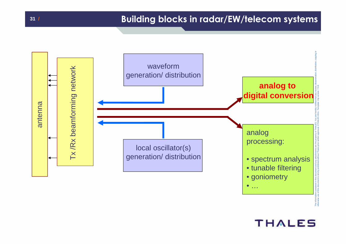
Building blocks in radar/EW/telecom systems
ante
nna
Tx
/Rx
beam
form
ing
netw
ork waveform
generation/ distribution
local oscillator(s) generation/ distribution
analog to digital conversion
analog processing:
• spectrum analysis• tunable filtering• goniometry• …
32 /32 /
The
info
rmat
ion
cont
aine
d in
this
doc
umen
t and
any
atta
chm
ents
are
the
prop
erty
of T
HA
LES
. You
are
her
eby
notif
ied
that
any
rev
iew
, dis
sem
inat
ion,
dis
trib
utio
n, c
opyi
ng o
r ot
herw
ise
use
of th
is d
ocum
ent i
s st
rictly
pro
hibi
ted
with
out T
hale
s pr
ior w
ritte
n ap
prov
al. ©
TH
ALE
S 2
011.
Tem
plat
e tr
tp v
ersi
on 7
.0.8
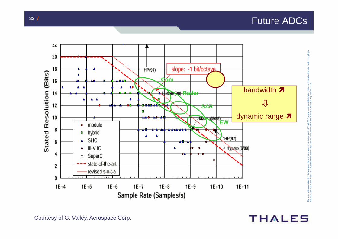
Future ADCs
Take Away – message clé du transparent: Arial 24
EW
SAR
Radar
Com
bandwidth
dynamic range
Courtesy of G. Valley, Aerospace Corp.
33 /33 /
The
info
rmat
ion
cont
aine
d in
this
doc
umen
t and
any
atta
chm
ents
are
the
prop
erty
of T
HA
LES
. You
are
her
eby
notif
ied
that
any
rev
iew
, dis
sem
inat
ion,
dis
trib
utio
n, c
opyi
ng o
r ot
herw
ise
use
of th
is d
ocum
ent i
s st
rictly
pro
hibi
ted
with
out T
hale
s pr
ior w
ritte
n ap
prov
al. ©
TH
ALE
S 2
011.
Tem
plat
e tr
tp v
ersi
on 7
.0.8
RF
LO
IF
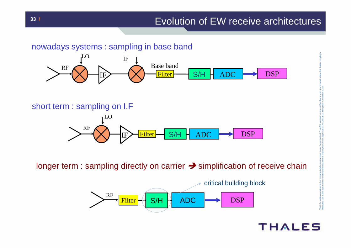
short term : sampling on I.F
Filter
nowadays systems : sampling in base band
RF
LO
IFBase band
IF
ADCFilter DSP
longer term : sampling directly on carrier � simplification of receive chain
ADCRF
Filter DSP
S/H
ADC DSPS/H
S/H
critical building block
Evolution of EW receive architectures
34 /34 /
The
info
rmat
ion
cont
aine
d in
this
doc
umen
t and
any
atta
chm
ents
are
the
prop
erty
of T
HA
LES
. You
are
her
eby
notif
ied
that
any
rev
iew
, dis
sem
inat
ion,
dis
trib
utio
n, c
opyi
ng o
r ot
herw
ise
use
of th
is d
ocum
ent i
s st
rictly
pro
hibi
ted
with
out T
hale
s pr
ior w
ritte
n ap
prov
al. ©
TH
ALE
S 2
011.
Tem
plat
e tr
tp v
ersi
on 7
.0.8
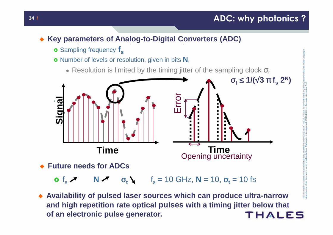
ADC: why photonics ?
Take Away – message clé du transparent: Arial 24
� Key parameters of Analog-to-Digital Converters (ADC)� Sampling frequency fs
� Number of levels or resolution, given in bits N,
� Resolution is limited by the timing jitter of the sampling clock σσσσt
,
Time
Sig
nal
� Future needs for ADCs
� fs N σσσσt fs = 10 GHz, N = 10, σσσσt = 10 fs
Opening uncertaintyTime
Err
or
σσσσt ≤≤≤≤ 1/(√√√√3 ππππ fs 2N)
� Availability of pulsed laser sources which can prod uce ultra-narrow and high repetition rate optical pulses with a timing jitter below that of an electronic pulse generator.
,
35 /35 /
The
info
rmat
ion
cont
aine
d in
this
doc
umen
t and
any
atta
chm
ents
are
the
prop
erty
of T
HA
LES
. You
are
her
eby
notif
ied
that
any
rev
iew
, dis
sem
inat
ion,
dis
trib
utio
n, c
opyi
ng o
r ot
herw
ise
use
of th
is d
ocum
ent i
s st
rictly
pro
hibi
ted
with
out T
hale
s pr
ior w
ritte
n ap
prov
al. ©
TH
ALE
S 2
011.
Tem
plat
e tr
tp v
ersi
on 7
.0.8
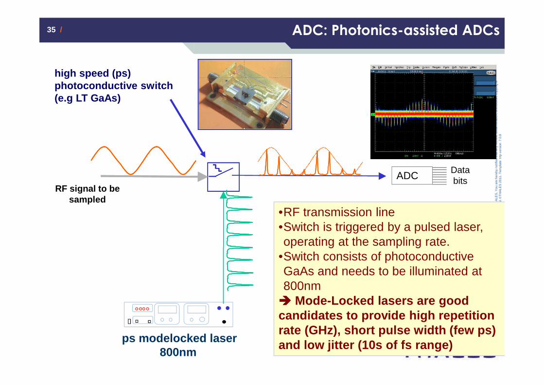
ADC: Photonics-assisted ADCs
RF signal to be sampled
ps modelocked laser800nm
high speed (ps) photoconductive switch (e.g LT GaAs)
ADCDatabits
•RF transmission line•Switch is triggered by a pulsed laser, operating at the sampling rate.
•Switch consists of photoconductive GaAs and needs to be illuminated at 800nm���� Mode-Locked lasers are good candidates to provide high repetition rate (GHz), short pulse width (few ps) and low jitter (10s of fs range)

36 /36 /
The
info
rmat
ion
cont
aine
d in
this
doc
umen
t and
any
atta
chm
ents
are
the
prop
erty
of T
HA
LES
. You
are
her
eby
notif
ied
that
any
rev
iew
, dis
sem
inat
ion,
dis
trib
utio
n, c
opyi
ng o
r ot
herw
ise
use
of th
is d
ocum
ent i
s st
rictly
pro
hibi
ted
with
out T
hale
s pr
ior w
ritte
n ap
prov
al. ©
TH
ALE
S 2
011.
Tem
plat
e tr
tp v
ersi
on 7
.0.8
• SOA + fiber loop
• P ≈ 2mW,
• ∆τ ≈ 8 ps @ frep = 18GHz,
• jitter ~ 47fs
SOA
MZM
RFV
FILTER COUPLER
-160
-140
-120
-100
-80
-60
-40
-20
0
10 100 1000 10000 100000 1000000 10000000
Frequency Offset (Hz)
Pha
s no
ise
(dB
c/H
z)
MLL additive phase noise at 18GHzRF synthesizer at 18 GHz absolute phase noise
Additive jitter 9 fs
Absolute jitter 46 fs
state-of-the art results for additive jitter @ 0.8 µm.
30 cm
MZM
Bragg
SOA
Coupler
Circulator
ADC: Realization of a mode locked [email protected]µm
37 /37 /
The
info
rmat
ion
cont
aine
d in
this
doc
umen
t and
any
atta
chm
ents
are
the
prop
erty
of T
HA
LES
. You
are
her
eby
notif
ied
that
any
rev
iew
, dis
sem
inat
ion,
dis
trib
utio
n, c
opyi
ng o
r ot
herw
ise
use
of th
is d
ocum
ent i
s st
rictly
pro
hibi
ted
with
out T
hale
s pr
ior w
ritte
n ap
prov
al. ©
TH
ALE
S 2
011.
Tem
plat
e tr
tp v
ersi
on 7
.0.8
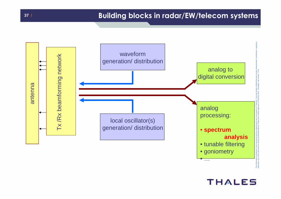
Building blocks in radar/EW/telecom systems
ante
nna
Tx
/Rx
beam
form
ing
netw
ork waveform
generation/ distribution
local oscillator(s) generation/ distribution
analog to digital conversion
analog processing:
• spectrumanalysis
• tunable filtering• goniometry• …
38 /38 /
The
info
rmat
ion
cont
aine
d in
this
doc
umen
t and
any
atta
chm
ents
are
the
prop
erty
of T
HA
LES
. You
are
her
eby
notif
ied
that
any
rev
iew
, dis
sem
inat
ion,
dis
trib
utio
n, c
opyi
ng o
r ot
herw
ise
use
of th
is d
ocum
ent i
s st
rictly
pro
hibi
ted
with
out T
hale
s pr
ior w
ritte
n ap
prov
al. ©
TH
ALE
S 2
011.
Tem
plat
e tr
tp v
ersi
on 7
.0.8
Remerciement
� TRT : G. Baili, P. Berger, J. Bourderionnet, D. Dol fi, S. Combrié, A. De Rossi, G. Pillet, V. Crozatier….
� III-Vlab : F. Van Dijk, M. Faugeron, B. Gérard,….
� TSA, TR6, TAS :
S. Formont, L. Ménager, T. Merlet, J. Schiellein, M. Maignan, M. Sotom
� IEMN, IEF, LAC, IPR, UCL, UDE,…
� DGA, EDA, ANR, FP7,…
Merci de votre attention !