Embed Size (px)
Citation preview
PIAGGIO WOULD LIKE TO THANK YOU
for choosing one of its products. We have prepared this manual to help you to get the very best from your scooter. Please read it carefully before ridingthe scooter for the first time. It contains information, tips and precautions for using your scooter. It also describes features, details and devices to assureyou that you have made the right choice. We believe that if you follow our suggestions, you will soon get to know your new vehicle and it will serve youwell for a long time to come. This booklet forms an integral part of the scooter; should the scooter be sold, it must be transferred to the new owner.
Carnaby es 125 - 200
Ed. 2
The instructions given in this manual are intended to provide a clear, simple guide to using your scooter; this booklet also details routine maintenanceprocedures and regular checks that should be carried out on the vehicle at an authorised Dealer or Service Centre. The booklet also containsinstructions for simple repairs. Any operations not specifically described in this manual require the use of special tools and/or particular technicalknowledge: to carry out these operations refer to any authorised Dealer of Service Centres.
2
Personal safety
Failure to completely observe these instructions will result in serious risk of personalinjury.
Safeguarding the environment
Sections marked with this symbol indicate the correct use of the vehicle to prevent dam-aging the environment.
Vehicle intactness
The incomplete or non-observance of these regulations leads to the risk of seriousdamage to the vehicle and sometimes even the invalidity of the guarantee.
The signs that you see on this page are very important. They are used to highlight thoseparts of the booklet that should be read with particular care. As you can see, each signconsists of a different graphic symbol, making it quick and easy to locate the varioustopics.
3

4
INDEX
VEHICLE...................................................................................... 7Dashboard................................................................................ 9Analogue instrument panel....................................................... 11Clock......................................................................................... 11Key switch................................................................................. 12
Locking the steering wheel.................................................... 12Releasing the steering wheel................................................ 12
Switch direction indicators........................................................ 13Horn button............................................................................... 13Light switch............................................................................... 13Start-up button.......................................................................... 14Engine stop button.................................................................... 14Accessing the fuel tank............................................................. 14
Opening the saddle............................................................... 15Keys.......................................................................................... 15Identification.............................................................................. 16Bag clip..................................................................................... 16
USE.............................................................................................. 17Checks...................................................................................... 18Refuelling.................................................................................. 18Shock absorbers adjustment.................................................... 19Running in................................................................................. 20Starting up the engine............................................................... 21
Precautions........................................................................... 22Difficult start up......................................................................... 22Stopping the engine.................................................................. 23Stand......................................................................................... 24Automatic transmission............................................................. 24Safe driving............................................................................... 24
MAINTENANCE........................................................................... 27Engine oil level.......................................................................... 28
Engine oil level check............................................................ 28Engine oil top-up................................................................... 28
Warning light (insufficient oil pressure)................................. 28Engine oil change.................................................................. 29
Hub oil level.............................................................................. 30Tyres......................................................................................... 32Spark plug dismantlement........................................................ 32Removing the air filter............................................................... 34Air filter cleaning....................................................................... 34Secondary air system............................................................... 35Cooling fluid level...................................................................... 35Checking the brake oil level...................................................... 37
Braking system fluid top up................................................... 37Battery....................................................................................... 40
Use of a new battery............................................................. 40Long periods of inactivity.......................................................... 41Fuses........................................................................................ 42Front light group........................................................................ 46
Headlight adjustment............................................................. 46Front direction indicators........................................................... 48Rear optical unit........................................................................ 50Number plate light..................................................................... 52Rear-view mirrors...................................................................... 52Idle adjustment.......................................................................... 52Front and rear disc brake.......................................................... 53Puncture.................................................................................... 54Periods of inactivity................................................................... 55Cleaning the vehicle.................................................................. 55
TECHNICAL DATA...................................................................... 61Kit equipment............................................................................ 68
SPARE PARTS AND ACCESSORIES........................................ 69Warnings................................................................................... 70
PROGRAMMED MAINTENANCE............................................... 73Scheduled maintenance table................................................... 74
5

6

Carnaby es125 - 200
Chap. 01Vehicle
7
01_01
8
1 Ve
hicl
e
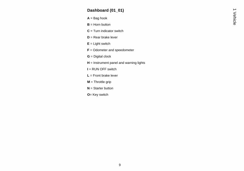
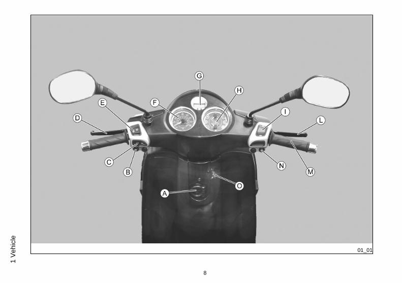
Dashboard (01_01)
A = Bag hook
B = Horn button
C = Turn indicator switch
D = Rear brake lever
E = Light switch
F = Odometer and speedometer
G = Digital clock
H = Instrument panel and warning lights
I = RUN OFF switch
L = Front brake lever
M = Throttle grip
N = Starter button
O= Key switch
9
1 Vehicle
01_02
10
1 Ve
hicl
e
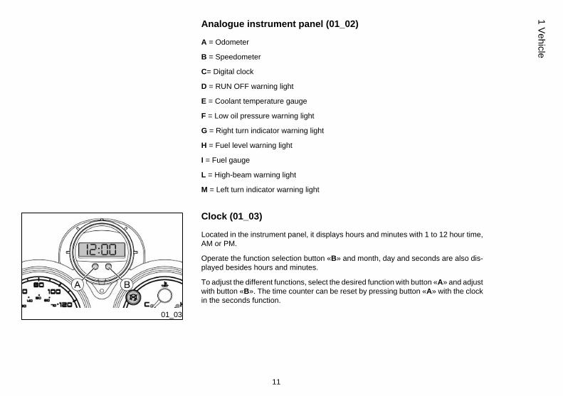
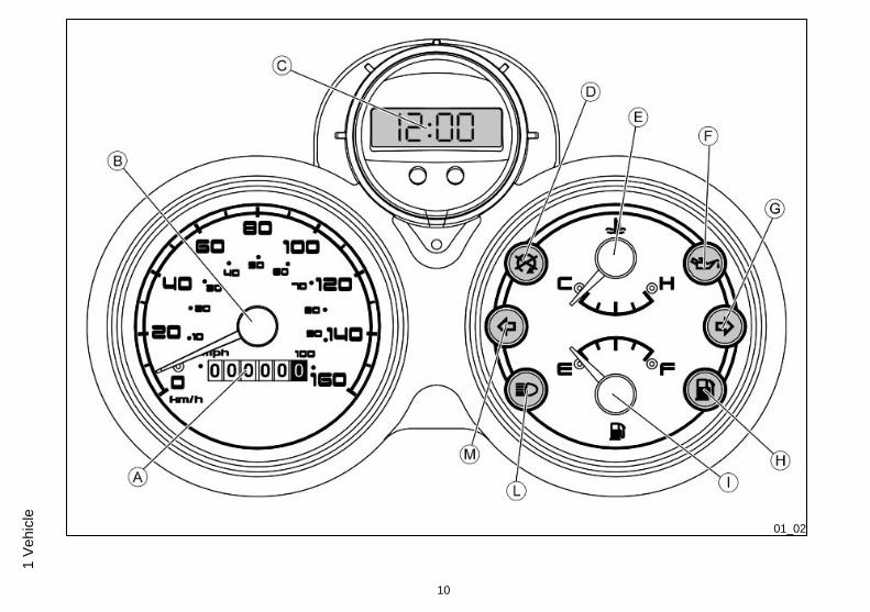
Analogue instrument panel (01_02)
A = Odometer
B = Speedometer
C= Digital clock
D = RUN OFF warning light
E = Coolant temperature gauge
F = Low oil pressure warning light
G = Right turn indicator warning light
H = Fuel level warning light
I = Fuel gauge
L = High-beam warning light
M = Left turn indicator warning light
01_03
Clock (01_03)
Located in the instrument panel, it displays hours and minutes with 1 to 12 hour time,AM or PM.
Operate the function selection button «B» and month, day and seconds are also dis-played besides hours and minutes.
To adjust the different functions, select the desired function with button «A» and adjustwith button «B». The time counter can be reset by pressing button «A» with the clockin the seconds function.
11
1 Vehicle
01_04
01_05
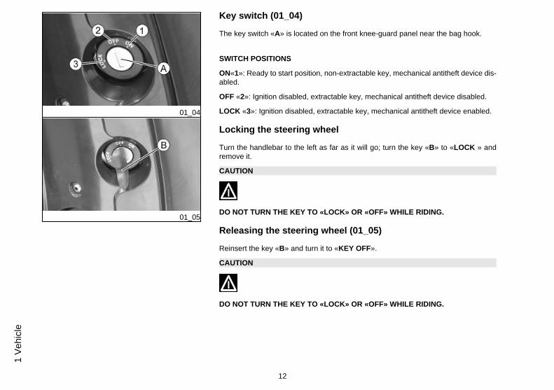
Key switch (01_04)
The key switch «A» is located on the front knee-guard panel near the bag hook.
SWITCH POSITIONS
ON«1»: Ready to start position, non-extractable key, mechanical antitheft device dis-abled.
OFF «2»: Ignition disabled, extractable key, mechanical antitheft device disabled.
LOCK «3»: Ignition disabled, extractable key, mechanical antitheft device enabled.
Locking the steering wheel
Turn the handlebar to the left as far as it will go; turn the key «B» to «LOCK » andremove it.
CAUTION
DO NOT TURN THE KEY TO «LOCK» OR «OFF» WHILE RIDING.
Releasing the steering wheel (01_05)
Reinsert the key «B» and turn it to «KEY OFF».
CAUTION
DO NOT TURN THE KEY TO «LOCK» OR «OFF» WHILE RIDING.
12
1 Ve
hicl
e

01_06
Switch direction indicators (01_06)
Lever «C» towards «1» = left turn indicators switched on;
Lever «C» towards «2» = right turn indicators switched on;
The lever «C» automatically goes back to its «0» position and the indicators remainon; push the lever «C» to turn them off.
01_07
Horn button (01_07)
Push the button «B» to sound the horn.
01_08
Light switch (01_08)
When the light switch «E» is set to «0», the low-beam light is on. When set to «1», thehigh-beam light is activated. If the light switch «E» is pressed when set to «2», thehigh-beam light is activated. The switch goes back to «0» automatically.
13
1 Vehicle
01_09
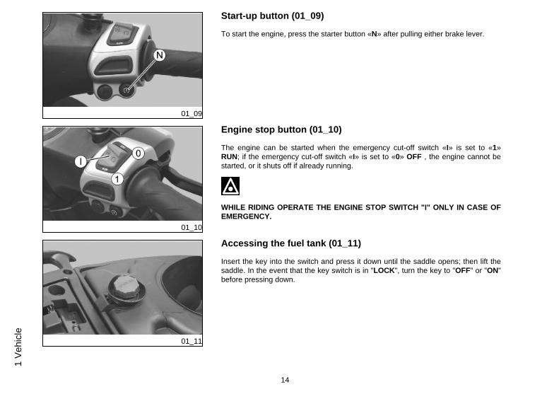
Start-up button (01_09)
To start the engine, press the starter button «N» after pulling either brake lever.
01_10
Engine stop button (01_10)
The engine can be started when the emergency cut-off switch «I» is set to «1»RUN; if the emergency cut-off switch «I» is set to «0» OFF , the engine cannot bestarted, or it shuts off if already running.
WHILE RIDING OPERATE THE ENGINE STOP SWITCH "I" ONLY IN CASE OFEMERGENCY.
01_11
Accessing the fuel tank (01_11)
Insert the key into the switch and press it down until the saddle opens; then lift thesaddle. In the event that the key switch is in "LOCK", turn the key to "OFF" or "ON"before pressing down.
14
1 Ve
hicl
e
01_12
01_13
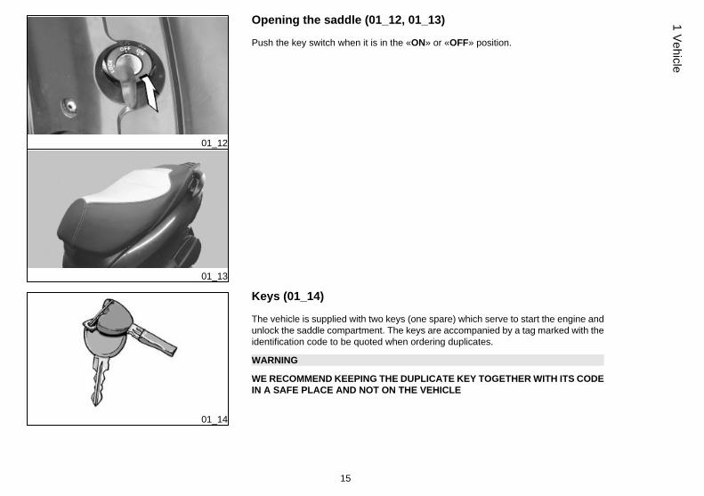
Opening the saddle (01_12, 01_13)
Push the key switch when it is in the «ON» or «OFF» position.
01_14
Keys (01_14)
The vehicle is supplied with two keys (one spare) which serve to start the engine andunlock the saddle compartment. The keys are accompanied by a tag marked with theidentification code to be quoted when ordering duplicates.
WARNING
WE RECOMMEND KEEPING THE DUPLICATE KEY TOGETHER WITH ITS CODEIN A SAFE PLACE AND NOT ON THE VEHICLE
15
1 Vehicle
01_15
01_16
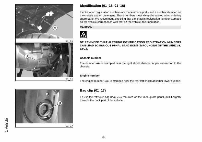
Identification (01_15, 01_16)
Identification registration numbers are made up of a prefix and a number stamped onthe chassis and on the engine. These numbers must always be quoted when orderingspare parts. We recommend checking that the chassis registration number stampedon the vehicle corresponds with that on the vehicle documentation.
CAUTION
BE REMINDED THAT ALTERING IDENTIFICATION REGISTRATION NUMBERSCAN LEAD TO SERIOUS PENAL SANCTIONS (IMPOUNDING OF THE VEHICLE,ETC.).
Chassis number
The number «A» is stamped near the right shock absorber upper connection to thechassis.
Engine number
The engine number «B» is stamped near the rear left shock absorber lower support.
01_17
Bag clip (01_17)
To use the retractile bag hook «B» mounted on the knee-guard panel, pull it slightlytowards the back part of the vehicle.
16
1 Ve
hicl
e
Carnaby es125 - 200
Chap. 02Use
17
Checks
Before using the vehicle, check:
1. That the fuel tank is full.
2. Front and rear brake fluid level
3. That the tyres are properly inflated.
4. The correct functioning of the tail lights, the headlamp, the turn indicators, the stoplight and the license plate light.
5. The correct functioning of the front and rear brakes.
6. The oil level in the gearcase.
7. The engine oil level.
8. The coolant level.
02_01
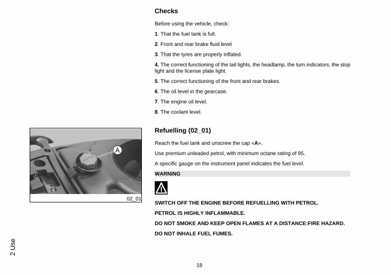
Refuelling (02_01)
Reach the fuel tank and unscrew the cap «A».
Use premium unleaded petrol, with minimum octane rating of 95.
A specific gauge on the instrument panel indicates the fuel level.
WARNING
SWITCH OFF THE ENGINE BEFORE REFUELLING WITH PETROL.
PETROL IS HIGHLY INFLAMMABLE.
DO NOT SMOKE AND KEEP OPEN FLAMES AT A DISTANCE:FIRE HAZARD.
DO NOT INHALE FUEL FUMES.
18
2 U
se
DO NOT ALLOW PETROL TO COME INTO CONTACT WITH HOT ENGINE ORANY PLASTIC PARTS.
CAUTION
PETROL DAMAGES THE PLASTIC PARTS OF THE BODYWORK.
02_02
02_03
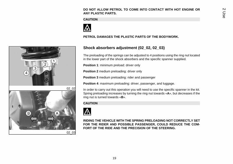
Shock absorbers adjustment (02_02, 02_03)
The preloading of the springs can be adjusted to 4 positions using the ring nut locatedin the lower part of the shock absorbers and the specific spanner supplied.
Position 1: minimum preload: driver only
Position 2 medium preloading: driver only
Position 3 medium preloading: rider and passenger
Position 4: maximum preloading: driver, passenger, and luggage.
In order to carry out this operation you will need to use the specific spanner in the kit.Spring preloading increases by turning the ring nut towards «A», but decreases if thering nut is turned towards «B».
CAUTION
RIDING THE VEHICLE WITH THE SPRING PRELOADING NOT CORRECTLY SETFOR THE RIDER AND POSSIBLE PASSENGER, COULD REDUCE THE COM-FORT OF THE RIDE AND THE PRECISION OF THE STEERING.
19
2 Use
WARNING
WE RECOMMEND WEARING GLOVES WHILE CARRYING OUT THIS OPERA-TION IN ORDER TO AVOID INJURIES.
WARNING
WE STRONGLY RECOMMEND NOT TO ADJUST BOTH SHOCK ABSORBERSWITH DIFFERENT PRELOADING
Running in
WARNING
DURING THE FIRST 1000 KM DO NOT RIDE THE VEHICLE OVER 80% OF ITSMAXIMUM SPEED. AVOID TWISTING THE THROTTLE GRIP FULLY OR KEEP-ING A CONSTANT SPEED ALONG LONG SECTIONS OF ROAD. AFTER THEFIRST 1000 KM, GRADUALLY INCREASE SPEED UNTIL REACHING THE MAX-IMUM PERFORMANCE.
20
2 U
se
02_04
02_05
02_06
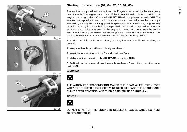
Starting up the engine (02_04, 02_05, 02_06)
The vehicle is supplied with an ignition cut-off system, activated by the emergencycut-off switch. The engine cannot start if the RUN/OFF switch is set to OFF. If theengine is running, it shuts off when the RUN/OFF switch is pressed when in OFF. Thescooter is equipped with automatic transmission with direct drive, so that starting iseffected by turning the throttle grip to idle speed; to start-off from still, progressivelytwist the throttle grip. The vehicle is equipped with an electric pump and a starter thatswitch on automatically as soon as the engine is started. In order to start the engineand before pressing the starter button «N», pull and hold the front brake lever «L» orthe rear brake lever «D» to actuate the specific start-up enabling switch
1. Rest the vehicle on its centre stand, ensuring the rear wheel is not touching theground.
2. Keep the throttle grip «M» completely untwisted.
3. Insert the key into the switch «O» and turn it to «ON».
4. Make sure that the switch «I» «RUN/OFF» is set to «RUN».
5. Pull the front brake lever «L » or the rear brake lever «D» and then press the starterbutton «N».
WARNING
THE AUTOMATIC TRANSMISSION MAKES THE REAR WHEEL TURN EVENWHEN THE THROTTLE IS SLIGHTLY TWISTED. RELEASE THE BRAKE CARE-FULLY AFTER STARTING, AND THEN ACCELERATE GRADUALLY.
CAUTION
DO NOT START-UP THE ENGINE IN CLOSED AREAS BECAUSE EXHAUSTGASES ARE TOXIC.
21
2 Use
Precautions
WARNING
NEVER STRESS THE ENGINE AT LOW TEMPERATURES IN ORDER TO AVOIDPOSSIBLE DAMAGE. BE CAREFUL NEVER TO EXCEED THE MAXIMUM SPEEDWHILE RUNNING DOWNHILL, IN ORDER TO AVOID DAMAGING THE ENGINE.IN ANY CASE, IN ORDER TO PRESERVE THE ENGINE FROM PROLONGED EX-CESSIVE REVOLUTIONS, THE REVOLUTION LIMITER WILL BE ACTIVATED IFTHE ENGINE SPEED EXCEEDS THE ESTABLISHED THRESHOLD. DO NOT AC-TIVATE THE REVOLUTION LIMITER RECURRENTLY SO AS TO AVOID DAM-AGING THE CATALYTIC CONVERTER.
WARNING
AFTER A LONG DISTANCE COVERED AT THE MAXIMUM SPEED, DO NOT STOPTHE ENGINE IMMEDIATELY, BUT LET IT RUN AT IDLE FOR A FEW SECONDS.
02_07
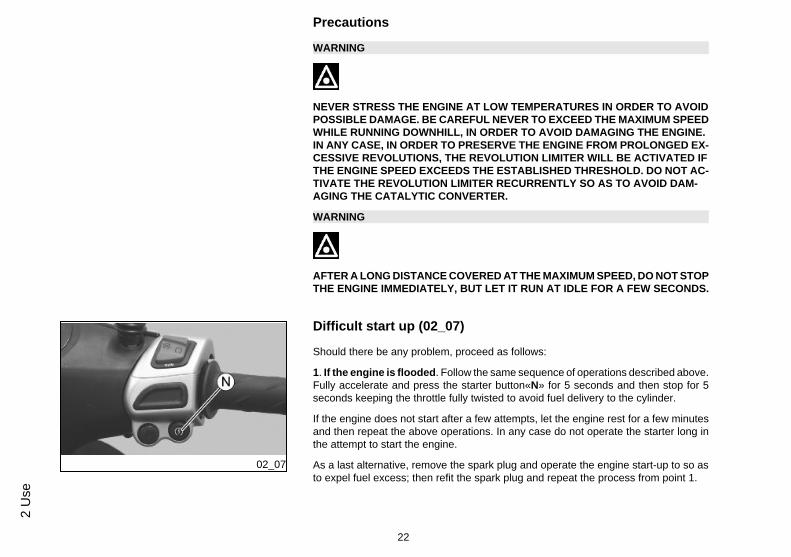
Difficult start up (02_07)
Should there be any problem, proceed as follows:
1. If the engine is flooded. Follow the same sequence of operations described above.Fully accelerate and press the starter button«N» for 5 seconds and then stop for 5seconds keeping the throttle fully twisted to avoid fuel delivery to the cylinder.
If the engine does not start after a few attempts, let the engine rest for a few minutesand then repeat the above operations. In any case do not operate the starter long inthe attempt to start the engine.
As a last alternative, remove the spark plug and operate the engine start-up to so asto expel fuel excess; then refit the spark plug and repeat the process from point 1.
22
2 U
se
2. If the engine overheats. Follow the same sequence of operations keeping thethrottle grip slightly twisted.
If the scooter fails to start even after using any of the procedures described above,take it to an Authorised Dealer or Service Centre.
02_08
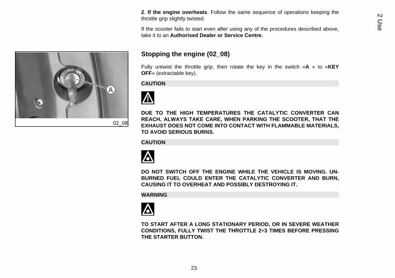
Stopping the engine (02_08)
Fully untwist the throttle grip, then rotate the key in the switch «A » to «KEYOFF» (extractable key).
CAUTION
DUE TO THE HIGH TEMPERATURES THE CATALYTIC CONVERTER CANREACH, ALWAYS TAKE CARE, WHEN PARKING THE SCOOTER, THAT THEEXHAUST DOES NOT COME INTO CONTACT WITH FLAMMABLE MATERIALS,TO AVOID SERIOUS BURNS.
CAUTION
DO NOT SWITCH OFF THE ENGINE WHILE THE VEHICLE IS MOVING. UN-BURNED FUEL COULD ENTER THE CATALYTIC CONVERTER AND BURN,CAUSING IT TO OVERHEAT AND POSSIBLY DESTROYING IT.
WARNING
TO START AFTER A LONG STATIONARY PERIOD, OR IN SEVERE WEATHERCONDITIONS, FULLY TWIST THE THROTTLE 2÷3 TIMES BEFORE PRESSINGTHE STARTER BUTTON.
23
2 Use
02_09
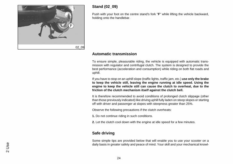
Stand (02_09)
Push with your foot on the centre stand's fork "F" while lifting the vehicle backward,holding onto the handlebar.
Automatic transmission
To ensure simple, pleasurable riding, the vehicle is equipped with automatic trans-mission with regulator and centrifugal clutch. The system is designed to provide thebest performance (acceleration and consumption) while riding on both flat roads anduphill.
If you have to stop on an uphill slope (traffic lights, traffic jam, etc.) use only the braketo keep the vehicle still, leaving the engine running at idle speed. Using theengine to keep the vehicle still can cause the clutch to overheat, due to thefriction of the clutch mechanism itself against the clutch bell.
It is therefore recommended to avoid conditions of prolonged clutch slippage (otherthan those previously indicated) like driving uphill fully laden on steep slopes or startingoff with driver and passenger at slopes with steepness greater than 25%.
Observe the following precautions if the clutch overheats:
1. Do not continue riding in such conditions.
2. Let the clutch cool down with the engine at idle speed for a few minutes.
Safe driving
Some simple tips are provided below that will enable you to use your scooter on adaily basis in greater safety and peace of mind. Your skill and your mechanical knowl-
24
2 U
se
edge are the basis of a safe ride. We recommend trying out the vehicle in traffic - freezones, in order to acquire a good knowledge of the vehicle it self.1. Before riding off, remember to put on your helmet and fasten it correctly.
2.Reduce speed on rough roads and drive with care.
3. After driving on a long stretch of wet road without using the brakes, the brakingeffect is initially lower. In these conditions, it is a good idea to apply the brakes fromtime to time.
4. Do not brake hard on wet, unsurfaced or slippery road surfaces.
5. Avoid riding off by mounting the scooter when resting on the support. In any case,the rear wheel should not be turning when in comes into contact with the ground, inorder to avoid abrupt departures.
6. If driving over roads affected by sand, mud, snow mixed with salt, etc. we recom-mend cleaning the brake disc with a non-corrosive detergent frequently in order toprevent corrosive particles from building up in the holes, which may cause early breakpad wear.
CAUTION
ALWAYS RIDE WITHIN YOUR LIMITS RIDING UNDER THE INFLUENCE OF AL-COHOL OR OTHER DRUGS AND CERTAIN MEDICATIONS IS EXTREMELY DAN-GEROUS.
CAUTION
ANY CHANGES TO THE VEHICLE PERFORMANCE AS WELL AS ALTERATIONSTO ORIGINAL STRUCTURAL PARTS IS STRICTLY FORBIDDEN BY LAW, ANDRENDERS THE VEHICLE NO LONGER CONFORMING TO THE APPROVED TYPEAND DANGEROUS FOR RIDING.
25
2 Use
CAUTION
DO NOT ADJUST THE MIRRORS WHILE RIDING. THIS COULD CAUSE YOU TOLOOSE CONTROL OF THE VEHICLE.
WARNING
IN ORDER TO PREVENT ANY ACCIDENTS RIDE VERY CAREFULLY WHENADDING ACCESSORIES AND CARRYING LUGGAGE. THE ADDITION OF AC-CESSORIES AND BAGGAGE CAN REDUCE THE STABILITY AND PERFORM-ANCE OF THE SCOOTER, AS WELL AS DECREASE THE LEVEL OF SAFETYDURING ITS USE. NEVER DRIVE THE SCOOTER EQUIPPED WITH ACCESSO-RIES AT A SPEED HIGHER THAN 100 km/h (see section "SPARE PARTS ANDACCESSORIES").
26
2 U
se
Carnaby es125 - 200
Chap. 03Maintenance
27
03_01
03_02
03_03
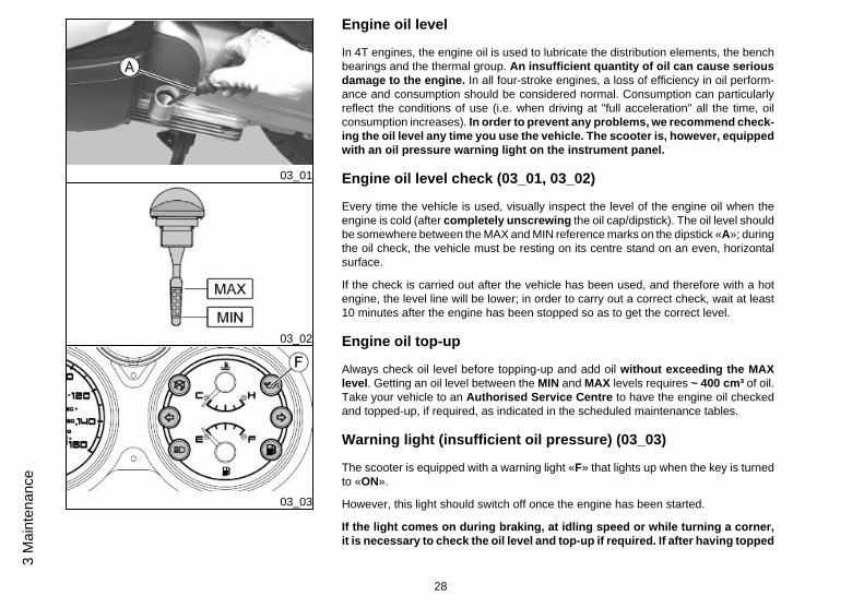
Engine oil level
In 4T engines, the engine oil is used to lubricate the distribution elements, the benchbearings and the thermal group. An insufficient quantity of oil can cause seriousdamage to the engine. In all four-stroke engines, a loss of efficiency in oil perform-ance and consumption should be considered normal. Consumption can particularlyreflect the conditions of use (i.e. when driving at "full acceleration" all the time, oilconsumption increases). In order to prevent any problems, we recommend check-ing the oil level any time you use the vehicle. The scooter is, however, equippedwith an oil pressure warning light on the instrument panel.
Engine oil level check (03_01, 03_02)
Every time the vehicle is used, visually inspect the level of the engine oil when theengine is cold (after completely unscrewing the oil cap/dipstick). The oil level shouldbe somewhere between the MAX and MIN reference marks on the dipstick «A»; duringthe oil check, the vehicle must be resting on its centre stand on an even, horizontalsurface.
If the check is carried out after the vehicle has been used, and therefore with a hotengine, the level line will be lower; in order to carry out a correct check, wait at least10 minutes after the engine has been stopped so as to get the correct level.
Engine oil top-up
Always check oil level before topping-up and add oil without exceeding the MAXlevel. Getting an oil level between the MIN and MAX levels requires ~ 400 cm³ of oil.Take your vehicle to an Authorised Service Centre to have the engine oil checkedand topped-up, if required, as indicated in the scheduled maintenance tables.
Warning light (insufficient oil pressure) (03_03)
The scooter is equipped with a warning light «F» that lights up when the key is turnedto «ON».
However, this light should switch off once the engine has been started.
If the light comes on during braking, at idling speed or while turning a corner,it is necessary to check the oil level and top-up if required. If after having topped
28
3 M
aint
enan
ce
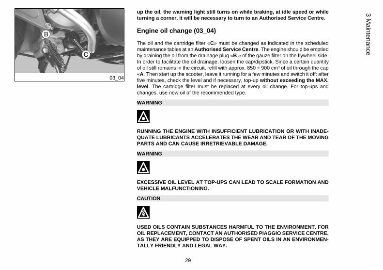
03_04
up the oil, the warning light still turns on while braking, at idle speed or whileturning a corner, it will be necessary to turn to an Authorised Service Centre.
Engine oil change (03_04)
The oil and the cartridge filter «C» must be changed as indicated in the scheduledmaintenance tables at an Authorised Service Centre. The engine should be emptiedby draining the oil from the drainage plug «B » of the gauze filter on the flywheel side.In order to facilitate the oil drainage, loosen the cap/dipstick. Since a certain quantityof oil still remains in the circuit, refill with approx. 850 ÷ 900 cm³ of oil through the cap«A. Then start up the scooter, leave it running for a few minutes and switch it off: afterfive minutes, check the level and if necessary, top-up without exceeding the MAX.level. The cartridge filter must be replaced at every oil change. For top-ups andchanges, use new oil of the recommended type.
WARNING
RUNNING THE ENGINE WITH INSUFFICIENT LUBRICATION OR WITH INADE-QUATE LUBRICANTS ACCELERATES THE WEAR AND TEAR OF THE MOVINGPARTS AND CAN CAUSE IRRETRIEVABLE DAMAGE.
WARNING
EXCESSIVE OIL LEVEL AT TOP-UPS CAN LEAD TO SCALE FORMATION ANDVEHICLE MALFUNCTIONING.
CAUTION
USED OILS CONTAIN SUBSTANCES HARMFUL TO THE ENVIRONMENT. FOROIL REPLACEMENT, CONTACT AN AUTHORISED PIAGGIO SERVICE CENTRE,AS THEY ARE EQUIPPED TO DISPOSE OF SPENT OILS IN AN ENVIRONMEN-TALLY FRIENDLY AND LEGAL WAY.
29
3 Maintenance
CAUTION
USING OILS OTHER THAN THOSE RECOMMENDED CAN SHORTEN THE LIFEOF THE ENGINE.
Recommended productsAGIP CITY HI TEC 4T
Engine oilSAE 5W-40, API SL, ACEA A3, JASO MA Synthetic oil
03_05
03_06
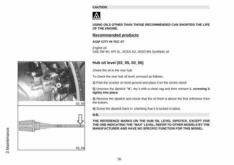
Hub oil level (03_05, 03_06)
Check the oil in the rear hub.
To check the rear hub oil level, proceed as follows:
1) Park the scooter on level ground and place it on the centre stand.
2) Unscrew the dipstick "A", dry it with a clean rag and then reinsert it, screwing ittightly into place;
3) Remove the dipstick and check that the oil level is above the first reference fromthe bottom.
4) Screw the dipstick back in, checking that it is locked in place.
N.B.
THE REFERENCE MARKS ON THE HUB OIL LEVEL DIPSTICK, EXCEPT FORTHE ONE INDICATING THE "MAX" LEVEL, REFER TO OTHER MODELS BY THEMANUFACTURER AND HAVE NO SPECIFIC FUNCTION FOR THIS MODEL.
30
3 M
aint
enan
ce
CAUTION
RIDING THE VEHICLE WITH INSUFFICIENT HUB LUBRICATION OR WITH CON-TAMINATED OR IMPROPER LUBRICANTS ACCELERATES THE WEAR ANDTEAR OF THE MOVING PARTS AND CAN CAUSE SERIOUS DAMAGE.
CAUTION
USED OILS CONTAIN SUBSTANCES HARMFUL TO THE ENVIRONMENT. FOROIL REPLACEMENT, CONTACT AN AUTHORISED SERVICE CENTRE, WHICHIS EQUIPPED TO DISPOSE OF USED OILS IN AN ENVIRONMENTALLY FRIEND-LY AND LEGAL WAY.
CAUTION
UPON REPLACING HUB OIL, AVOID THE OIL COMING INTO CONTACT WITHTHE REAR BRAKE DISC.
Recommended productsAGIP ROTRA 80W-90
Rear hub oilSAE 80W/90 Oil that exceeds the requirements of API GL3 specifications
CharacteristicHub Oil Quantity
See the Technical Data Chapter
31
3 Maintenance
03_07
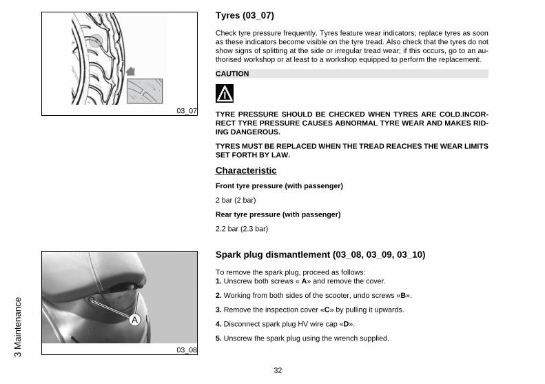
Tyres (03_07)
Check tyre pressure frequently. Tyres feature wear indicators; replace tyres as soonas these indicators become visible on the tyre tread. Also check that the tyres do notshow signs of splitting at the side or irregular tread wear; if this occurs, go to an au-thorised workshop or at least to a workshop equipped to perform the replacement.
CAUTION
TYRE PRESSURE SHOULD BE CHECKED WHEN TYRES ARE COLD.INCOR-RECT TYRE PRESSURE CAUSES ABNORMAL TYRE WEAR AND MAKES RID-ING DANGEROUS.
TYRES MUST BE REPLACED WHEN THE TREAD REACHES THE WEAR LIMITSSET FORTH BY LAW.
CharacteristicFront tyre pressure (with passenger)
2 bar (2 bar)
Rear tyre pressure (with passenger)
2.2 bar (2.3 bar)
03_08
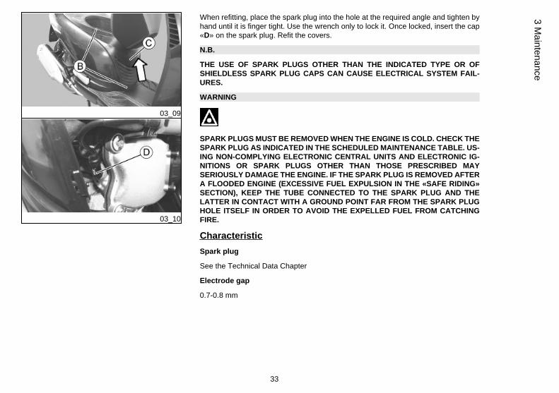
Spark plug dismantlement (03_08, 03_09, 03_10)
To remove the spark plug, proceed as follows:1. Unscrew both screws « A» and remove the cover.
2. Working from both sides of the scooter, undo screws «B».
3. Remove the inspection cover «C» by pulling it upwards.
4. Disconnect spark plug HV wire cap «D».
5. Unscrew the spark plug using the wrench supplied.
32
3 M
aint
enan
ce
03_09
03_10
When refitting, place the spark plug into the hole at the required angle and tighten byhand until it is finger tight. Use the wrench only to lock it. Once locked, insert the cap«D» on the spark plug. Refit the covers.
N.B.
THE USE OF SPARK PLUGS OTHER THAN THE INDICATED TYPE OR OFSHIELDLESS SPARK PLUG CAPS CAN CAUSE ELECTRICAL SYSTEM FAIL-URES.
WARNING
SPARK PLUGS MUST BE REMOVED WHEN THE ENGINE IS COLD. CHECK THESPARK PLUG AS INDICATED IN THE SCHEDULED MAINTENANCE TABLE. US-ING NON-COMPLYING ELECTRONIC CENTRAL UNITS AND ELECTRONIC IG-NITIONS OR SPARK PLUGS OTHER THAN THOSE PRESCRIBED MAYSERIOUSLY DAMAGE THE ENGINE. IF THE SPARK PLUG IS REMOVED AFTERA FLOODED ENGINE (EXCESSIVE FUEL EXPULSION IN THE «SAFE RIDING»SECTION), KEEP THE TUBE CONNECTED TO THE SPARK PLUG AND THELATTER IN CONTACT WITH A GROUND POINT FAR FROM THE SPARK PLUGHOLE ITSELF IN ORDER TO AVOID THE EXPELLED FUEL FROM CATCHINGFIRE.
CharacteristicSpark plug
See the Technical Data Chapter
Electrode gap
0.7-0.8 mm
33
3 Maintenance
03_11
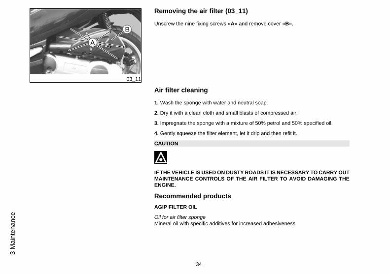
Removing the air filter (03_11)
Unscrew the nine fixing screws «A» and remove cover «B».
Air filter cleaning
1. Wash the sponge with water and neutral soap.
2. Dry it with a clean cloth and small blasts of compressed air.
3. Impregnate the sponge with a mixture of 50% petrol and 50% specified oil.
4. Gently squeeze the filter element, let it drip and then refit it.
CAUTION
IF THE VEHICLE IS USED ON DUSTY ROADS IT IS NECESSARY TO CARRY OUTMAINTENANCE CONTROLS OF THE AIR FILTER TO AVOID DAMAGING THEENGINE.
Recommended productsAGIP FILTER OIL
Oil for air filter spongeMineral oil with specific additives for increased adhesiveness
34
3 M
aint
enan
ce
03_12
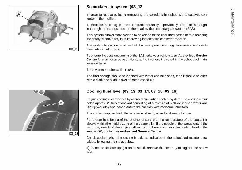
Secondary air system (03_12)
In order to reduce polluting emissions, the vehicle is furnished with a catalytic con-verter in the muffler.
To facilitate the catalytic process, a further quantity of previously filtered air is broughtin through the exhaust duct on the head by the secondary air system (SAS).
This system allows more oxygen to be added to the unburned gases before reachingthe catalytic converter, thus improving the catalytic converter reaction.
The system has a control valve that disables operation during deceleration in order toavoid abnormal noises.
To ensure the best functioning of the SAS, take your vehicle to an Authorised ServiceCentre for maintenance operations, at the intervals indicated in the scheduled main-tenance table.
This system requires a filter «A».
The filter sponge should be cleaned with water and mild soap, then it should be driedwith a cloth and slight blows of compressed air.
03_13
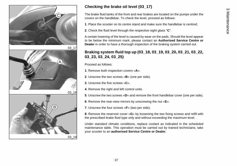
Cooling fluid level (03_13, 03_14, 03_15, 03_16)
Engine cooling is carried out by a forced-circulation coolant system. The cooling circuitholds approx. 2 litres of coolant consisting of a mixture of 50% de-ionised water and50% glycol ethylene-based antifreeze solution with corrosion inhibitors.
The coolant supplied with the scooter is already mixed and ready for use.
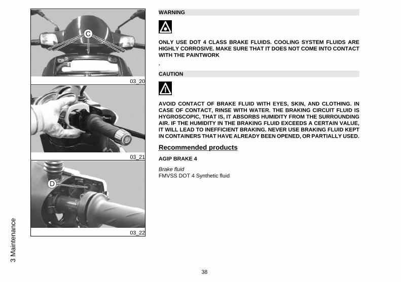
For proper functioning of the engine, ensure that the temperature of the coolant isalways within the middle zone of the gauge «E». If the needle of the gauge enters thered zone, switch off the engine, allow to cool down and check the coolant level; if thelevel is OK, contact an Authorised Service Centre.
Check coolant when the engine is cold as indicated in the scheduled maintenancetables, following the steps below.
a) Place the scooter upright on its stand. remove the cover by taking out the screw«A».
35
3 Maintenance
03_14
03_15
03_16
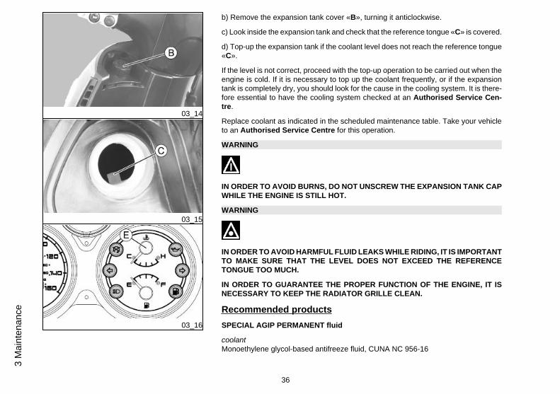
b) Remove the expansion tank cover «B», turning it anticlockwise.
c) Look inside the expansion tank and check that the reference tongue «C» is covered.
d) Top-up the expansion tank if the coolant level does not reach the reference tongue«C».
If the level is not correct, proceed with the top-up operation to be carried out when theengine is cold. If it is necessary to top up the coolant frequently, or if the expansiontank is completely dry, you should look for the cause in the cooling system. It is there-fore essential to have the cooling system checked at an Authorised Service Cen-tre.
Replace coolant as indicated in the scheduled maintenance table. Take your vehicleto an Authorised Service Centre for this operation.
WARNING
IN ORDER TO AVOID BURNS, DO NOT UNSCREW THE EXPANSION TANK CAPWHILE THE ENGINE IS STILL HOT.
WARNING
IN ORDER TO AVOID HARMFUL FLUID LEAKS WHILE RIDING, IT IS IMPORTANTTO MAKE SURE THAT THE LEVEL DOES NOT EXCEED THE REFERENCETONGUE TOO MUCH.
IN ORDER TO GUARANTEE THE PROPER FUNCTION OF THE ENGINE, IT ISNECESSARY TO KEEP THE RADIATOR GRILLE CLEAN.
Recommended productsSPECIAL AGIP PERMANENT fluid
coolantMonoethylene glycol-based antifreeze fluid, CUNA NC 956-16
36
3 M
aint
enan
ce
03_17
03_18
03_19
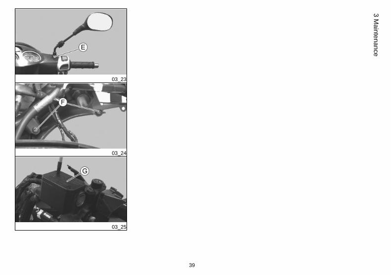
Checking the brake oil level (03_17)
The brake fluid tanks of the front and rear brakes are located on the pumps under thecovers on the handlebar. To check the level, proceed as follows:
1. Place the scooter on its centre stand and make sure the handlebar is centred;
2. Check the fluid level through the respective sight glass "C".
A certain lowering of the level is caused by wear on the pads. Should the level appearto be below the minimum mark, please contact an Authorised Service Centre orDealer in order to have a thorough inspection of the braking system carried out.
Braking system fluid top up (03_18, 03_19, 03_20, 03_21, 03_22,03_23, 03_24, 03_25)
Proceed as follows:
1. Remove both inspection covers «A».
2. Unscrew the two screws «B» (one per side).
3. Unscrew the five screws «C».
4. Remove the right and left control units.
5. Unscrew the two screws «D» and remove the front handlebar cover (one per side).
6. Remove the rear-view mirrors by unscrewing the nut «E».
7. Unscrew the four screws «F» (two per side).
8. Remove the reservoir cover «G» by loosening the two fixing screws and refill withthe prescribed brake fluid type only and without exceeding the maximum level.
Under standard climatic conditions, replace coolant as indicated in the scheduledmaintenance table. This operation must be carried out by trained technicians; takeyour scooter to an authorised Service Centre or Dealer.
37
3 Maintenance
03_20
03_21
03_22
WARNING
ONLY USE DOT 4 CLASS BRAKE FLUIDS. COOLING SYSTEM FLUIDS AREHIGHLY CORROSIVE. MAKE SURE THAT IT DOES NOT COME INTO CONTACTWITH THE PAINTWORK.
CAUTION
AVOID CONTACT OF BRAKE FLUID WITH EYES, SKIN, AND CLOTHING. INCASE OF CONTACT, RINSE WITH WATER. THE BRAKING CIRCUIT FLUID ISHYGROSCOPIC, THAT IS, IT ABSORBS HUMIDITY FROM THE SURROUNDINGAIR. IF THE HUMIDITY IN THE BRAKING FLUID EXCEEDS A CERTAIN VALUE,IT WILL LEAD TO INEFFICIENT BRAKING. NEVER USE BRAKING FLUID KEPTIN CONTAINERS THAT HAVE ALREADY BEEN OPENED, OR PARTIALLY USED.
Recommended productsAGIP BRAKE 4
Brake fluidFMVSS DOT 4 Synthetic fluid
38
3 M
aint
enan
ce
03_23
03_24
03_25
39
3 Maintenance
03_26
03_27
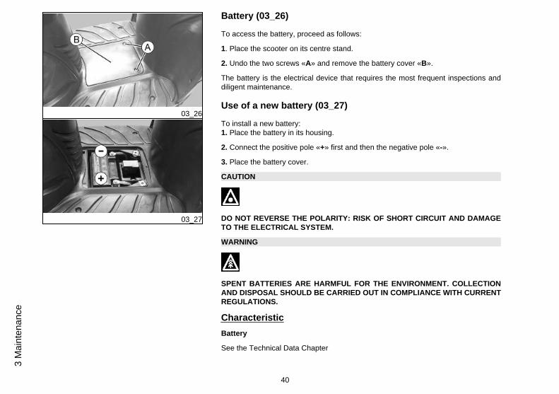
Battery (03_26)
To access the battery, proceed as follows:
1. Place the scooter on its centre stand.
2. Undo the two screws «A» and remove the battery cover «B».
The battery is the electrical device that requires the most frequent inspections anddiligent maintenance.
Use of a new battery (03_27)
To install a new battery:1. Place the battery in its housing.
2. Connect the positive pole «+» first and then the negative pole «-».
3. Place the battery cover.
CAUTION
DO NOT REVERSE THE POLARITY: RISK OF SHORT CIRCUIT AND DAMAGETO THE ELECTRICAL SYSTEM.
WARNING
SPENT BATTERIES ARE HARMFUL FOR THE ENVIRONMENT. COLLECTIONAND DISPOSAL SHOULD BE CARRIED OUT IN COMPLIANCE WITH CURRENTREGULATIONS.
CharacteristicBattery
See the Technical Data Chapter
40
3 M
aint
enan
ce
Long periods of inactivity
Battery performance will decrease if the vehicle is not used for a long time. This is theresult of the natural phenomenon of battery discharging plus residual absorption byvehicle components with constant power consumption. Poor battery performance mayalso be due to environmental conditions and the cleanness of the poles. In order toavoid difficult starts and/or irreversible damage to the battery, follow any of thesesteps:
- At least once a month start the engine and run it slightly above idle speed for 10-15minutes. This keeps all the engine components, as well as the battery, in good workingorder.
- Take your vehicle to a garage (as indicated in the "Vehicle not used for extendedperiods" section) to have the battery removed. Have the battery cleaned, charged fullyand stored in a dry, ventilated place. Recharge at least once every two months.
CAUTION
THE BATTERY MUST BE CHARGED WITH A CURRENT EQUAL TO 1/10 OF THERATED CAPACITY OF THE BATTERY AND FOR NOT LONGER THAN 10 HOURS.CONTACT AN AUTHORISED SERVICE CENTRE TO CARRY OUT THIS OPERA-TION SAFELY. WHEN REFITTING THE BATTERY MAKE SURE THE LEADS ARECORRECTLY CONNECTED TO THE TERMINALS.
WARNING
DO NOT DISCONNECT THE BATTERY CABLES WITH THE ENGINE RUNNING,THIS CAN CAUSE PERMANENT DAMAGE TO THE VEHICLE ELECTRONIC CON-TROL UNIT.
41
3 Maintenance
WARNING
SPENT BATTERIES ARE HARMFUL FOR THE ENVIRONMENT. COLLECTIONAND DISPOSAL SHOULD BE CARRIED OUT IN COMPLIANCE WITH CURRENTREGULATIONS.
03_28
03_29
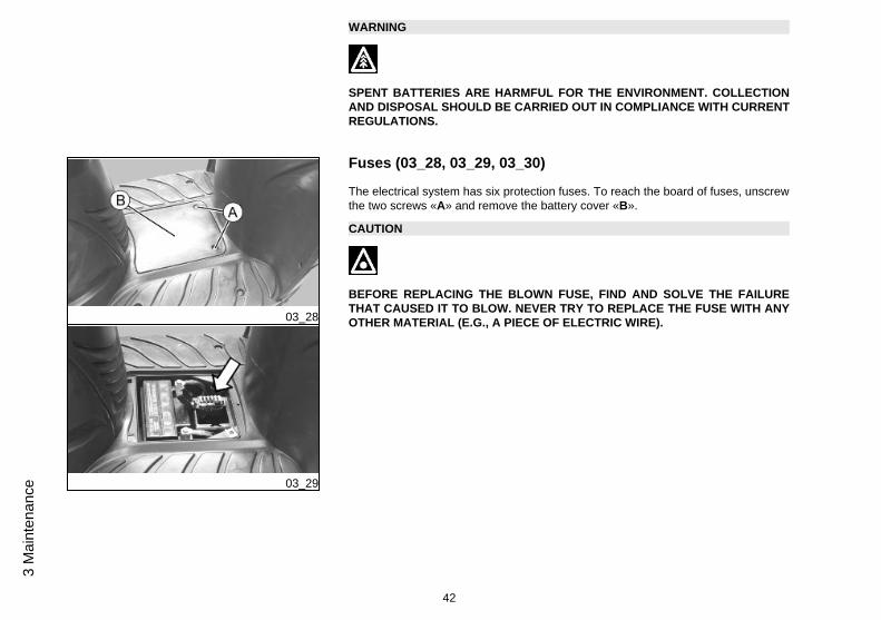
Fuses (03_28, 03_29, 03_30)
The electrical system has six protection fuses. To reach the board of fuses, unscrewthe two screws «A» and remove the battery cover «B».
CAUTION
BEFORE REPLACING THE BLOWN FUSE, FIND AND SOLVE THE FAILURETHAT CAUSED IT TO BLOW. NEVER TRY TO REPLACE THE FUSE WITH ANYOTHER MATERIAL (E.G., A PIECE OF ELECTRIC WIRE).
42
3 M
aint
enan
ce
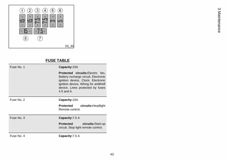
03_30
FUSE TABLEFuse No. 1 Capacity:15A
Protected circuits:Electric fan,Battery recharge circuit, Electronicignition device, Clock, Electronicignition device, Wiring for antitheftdevice, Lines protected by fuses4.5 and 6.
Fuse No. 2 Capacity:15A
Protected circuits:HeadlightRemote control.
Fuse No. 3 Capacity:7.5 A
Protected circuits:Start-upcircuit, Stop light remote control.
Fuse No. 4 Capacity:7.5 A
43
3 Maintenance
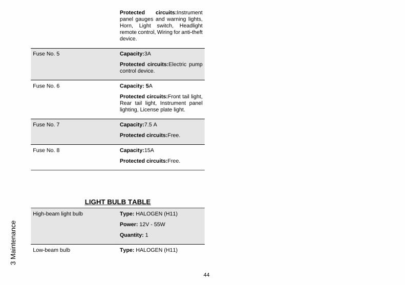
Protected circuits:Instrumentpanel gauges and warning lights,Horn, Light switch, Headlightremote control, Wiring for anti-theftdevice.
Fuse No. 5 Capacity:3A
Protected circuits:Electric pumpcontrol device.
Fuse No. 6 Capacity: 5A
Protected circuits:Front tail light,Rear tail light, Instrument panellighting, License plate light.
Fuse No. 7 Capacity:7.5 A
Protected circuits:Free.
Fuse No. 8 Capacity:15A
Protected circuits:Free.
LIGHT BULB TABLEHigh-beam light bulb Type: HALOGEN (H11)
Power: 12V - 55W
Quantity: 1
Low-beam bulb Type: HALOGEN (H11)
44
3 M
aint
enan
ce
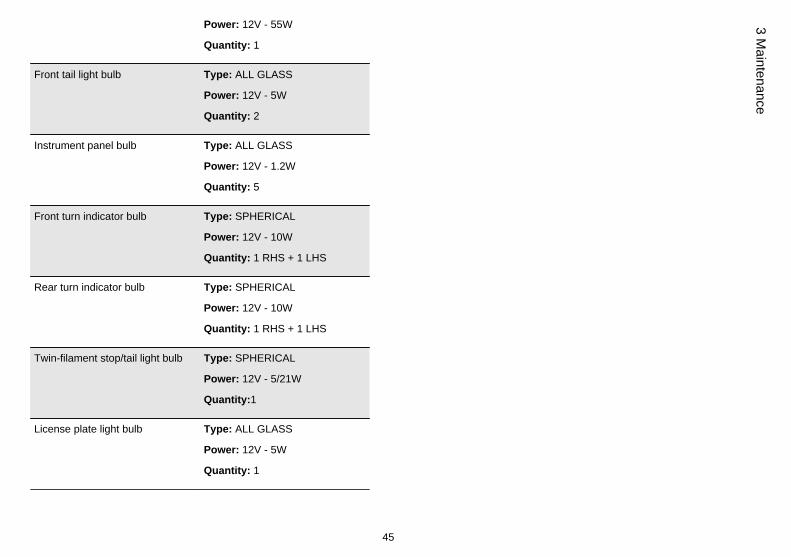
Power: 12V - 55W
Quantity: 1
Front tail light bulb Type: ALL GLASS
Power: 12V - 5W
Quantity: 2
Instrument panel bulb Type: ALL GLASS
Power: 12V - 1.2W
Quantity: 5
Front turn indicator bulb Type: SPHERICAL
Power: 12V - 10W
Quantity: 1 RHS + 1 LHS
Rear turn indicator bulb Type: SPHERICAL
Power: 12V - 10W
Quantity: 1 RHS + 1 LHS
Twin-filament stop/tail light bulb Type: SPHERICAL
Power: 12V - 5/21W
Quantity:1
License plate light bulb Type: ALL GLASS
Power: 12V - 5W
Quantity: 1
45
3 Maintenance
03_31
03_32
03_33
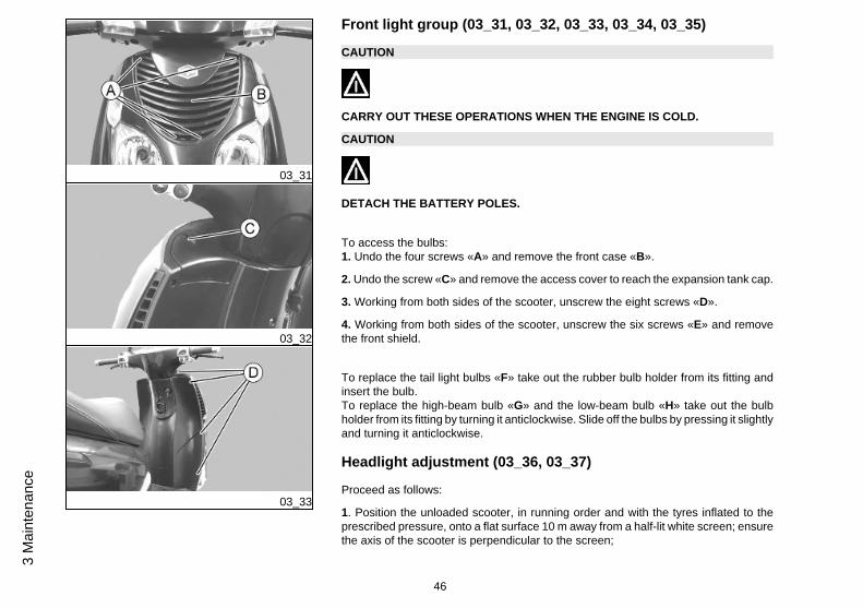
Front light group (03_31, 03_32, 03_33, 03_34, 03_35)
CAUTION
CARRY OUT THESE OPERATIONS WHEN THE ENGINE IS COLD.
CAUTION
DETACH THE BATTERY POLES.
To access the bulbs:1. Undo the four screws «A» and remove the front case «B».
2. Undo the screw «C» and remove the access cover to reach the expansion tank cap.
3. Working from both sides of the scooter, unscrew the eight screws «D».
4. Working from both sides of the scooter, unscrew the six screws «E» and removethe front shield.
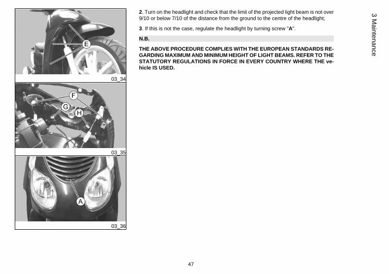
To replace the tail light bulbs «F» take out the rubber bulb holder from its fitting andinsert the bulb.To replace the high-beam bulb «G» and the low-beam bulb «H» take out the bulbholder from its fitting by turning it anticlockwise. Slide off the bulbs by pressing it slightlyand turning it anticlockwise.
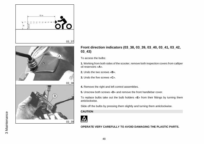
Headlight adjustment (03_36, 03_37)
Proceed as follows:
1. Position the unloaded scooter, in running order and with the tyres inflated to theprescribed pressure, onto a flat surface 10 m away from a half-lit white screen; ensurethe axis of the scooter is perpendicular to the screen;
46
3 M
aint
enan
ce
03_34
03_35
03_36
2. Turn on the headlight and check that the limit of the projected light beam is not over9/10 or below 7/10 of the distance from the ground to the centre of the headlight;
3. If this is not the case, regulate the headlight by turning screw "A".
N.B.
THE ABOVE PROCEDURE COMPLIES WITH THE EUROPEAN STANDARDS RE-GARDING MAXIMUM AND MINIMUM HEIGHT OF LIGHT BEAMS. REFER TO THESTATUTORY REGULATIONS IN FORCE IN EVERY COUNTRY WHERE THE ve-hicle IS USED.
47
3 Maintenance
03_37
03_38
03_39
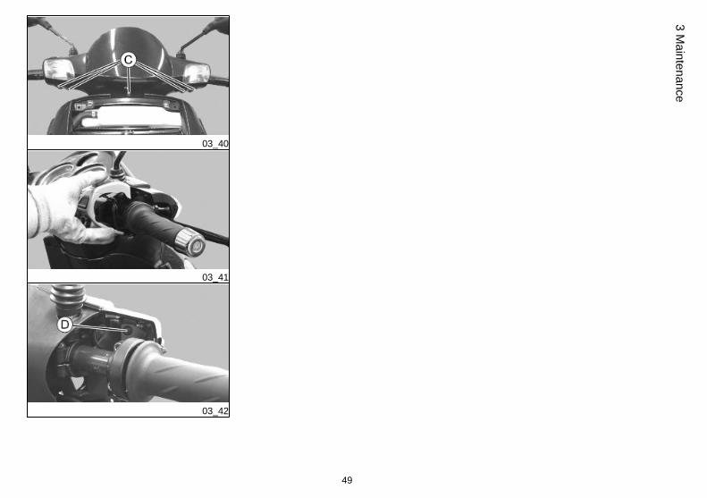
Front direction indicators (03_38, 03_39, 03_40, 03_41, 03_42,03_43)
To access the bulbs:
1. Working from both sides of the scooter, remove both inspection covers from calliperoil reservoirs «A».
2. Undo the two screws «B».
3. Undo the five screws «C».
4. Remove the right and left control assemblies.
5. Unscrew both screws «D» and remove the front handlebar cover.
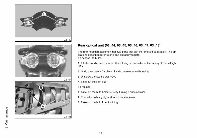
To replace bulbs take out the bulb holders «E» from their fittings by turning themanticlockwise.
Slide off the bulbs by pressing them slightly and turning them anticlockwise.
CAUTION
OPERATE VERY CAREFULLY TO AVOID DAMAGING THE PLASTIC PARTS.
48
3 M
aint
enan
ce
03_40
03_41
03_42
49
3 Maintenance
03_43
03_44
03_45
Rear optical unit (03_44, 03_45, 03_46, 03_47, 03_48)
The rear headlight assembly has two parts that can be removed separately. The op-erations described refer to one part but apply to both.To access the bulbs:
1. Lift the saddle and undo the three fixing screws «A» of the fairing of the tail light«B».
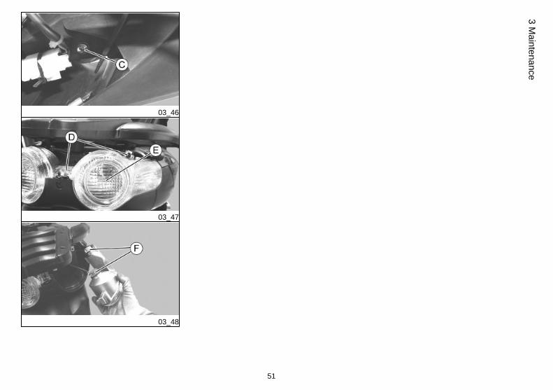
2. Undo the screw «C» placed inside the rear wheel housing.
3. Unscrew the two screws «D».
4. Take out the light «E».
To replace:
1. Take out the bulb holder «F» by turning it anticlockwise.
2. Press the bulb slightly and turn it anticlockwise.
3. Take out the bulb from its fitting.
50
3 M
aint
enan
ce
03_46
03_47
03_48
51
3 Maintenance
03_49
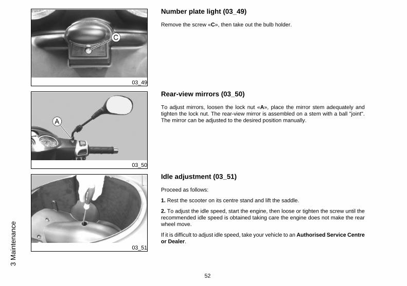
Number plate light (03_49)
Remove the screw «C», then take out the bulb holder.
03_50
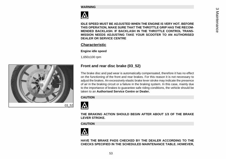
Rear-view mirrors (03_50)
To adjust mirrors, loosen the lock nut «A», place the mirror stem adequately andtighten the lock nut. The rear-view mirror is assembled on a stem with a ball "joint".The mirror can be adjusted to the desired position manually.
03_51
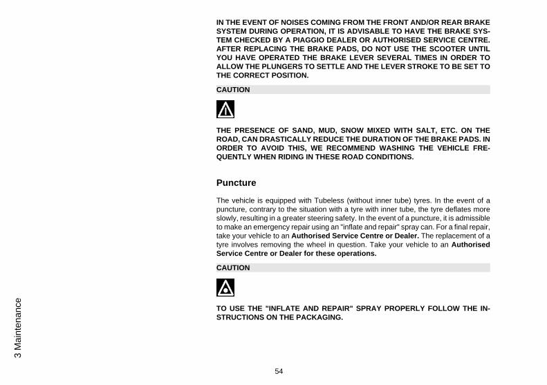
Idle adjustment (03_51)
Proceed as follows:
1. Rest the scooter on its centre stand and lift the saddle.
2. To adjust the idle speed, start the engine, then loose or tighten the screw until therecommended idle speed is obtained taking care the engine does not make the rearwheel move.
If it is difficult to adjust idle speed, take your vehicle to an Authorised Service Centreor Dealer.
52
3 M
aint
enan
ce
WARNING
IDLE SPEED MUST BE ADJUSTED WHEN THE ENGINE IS VERY HOT. BEFORETHIS OPERATION, MAKE SURE THAT THE THROTTLE GRIP HAS THE RECOM-MENDED BACKLASH. IF BACKLASH IN THE THROTTLE CONTROL TRANS-MISSION NEEDS ADJUSTING TAKE YOUR SCOOTER TO AN AUTHORISEDDEALER OR SERVICE CENTRE
CharacteristicEngine idle speed
1,650±100 rpm
03_52
Front and rear disc brake (03_52)
The brake disc and pad wear is automatically compensated, therefore it has no effecton the functioning of the front and rear brakes. For this reason it is not necessary toadjust the brakes. An excessively elastic brake lever stroke may indicate the presenceof air in the braking circuit or a failure in the braking system. In this case, mainly dueto the importance of brakes to guarantee safe riding conditions, the vehicle should betaken to an Authorised Service Centre or Dealer.
CAUTION
THE BRAKING ACTION SHOULD BEGIN AFTER ABOUT 1/3 OF THE BRAKELEVER STROKE.
CAUTION
HAVE THE BRAKE PADS CHECKED BY THE DEALER ACCORDING TO THECHECKS SPECIFIED IN THE SCHEDULED MAINTENANCE TABLE. HOWEVER,
53
3 Maintenance
IN THE EVENT OF NOISES COMING FROM THE FRONT AND/OR REAR BRAKESYSTEM DURING OPERATION, IT IS ADVISABLE TO HAVE THE BRAKE SYS-TEM CHECKED BY A PIAGGIO DEALER OR AUTHORISED SERVICE CENTRE.AFTER REPLACING THE BRAKE PADS, DO NOT USE THE SCOOTER UNTILYOU HAVE OPERATED THE BRAKE LEVER SEVERAL TIMES IN ORDER TOALLOW THE PLUNGERS TO SETTLE AND THE LEVER STROKE TO BE SET TOTHE CORRECT POSITION.
CAUTION
THE PRESENCE OF SAND, MUD, SNOW MIXED WITH SALT, ETC. ON THEROAD, CAN DRASTICALLY REDUCE THE DURATION OF THE BRAKE PADS. INORDER TO AVOID THIS, WE RECOMMEND WASHING THE VEHICLE FRE-QUENTLY WHEN RIDING IN THESE ROAD CONDITIONS.
Puncture
The vehicle is equipped with Tubeless (without inner tube) tyres. In the event of apuncture, contrary to the situation with a tyre with inner tube, the tyre deflates moreslowly, resulting in a greater steering safety. In the event of a puncture, it is admissibleto make an emergency repair using an "inflate and repair" spray can. For a final repair,take your vehicle to an Authorised Service Centre or Dealer. The replacement of atyre involves removing the wheel in question. Take your vehicle to an AuthorisedService Centre or Dealer for these operations.
CAUTION
TO USE THE "INFLATE AND REPAIR" SPRAY PROPERLY FOLLOW THE IN-STRUCTIONS ON THE PACKAGING.
54
3 M
aint
enan
ce
WARNING
THE WHEELS FITTED WITH TYRES SHOULD ALWAYS BE BALANCED. RIDINGTHE VEHICLE WITH VERY LOW TYRE PRESSURE OR WITH INCORRECTLYBALANCED TYRES CAN LEAD TO DANGEROUS STEERING VIBRATIONS.
03_53
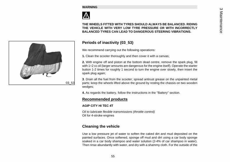
Periods of inactivity (03_53)
We recommend carrying out the following operations:
1. Clean the scooter thoroughly and then cover it with a canvas;
2. With engine off and piston at the bottom dead centre, remove the spark plug, fillwith 1÷2 cc oil (larger amounts are dangerous for the engine itself). Operate the starterbutton 1-2 times for roughly 1 second to turn the engine over slowly, then insert thespark plug again;
3. Drain all the fuel from the scooter; spread antirust grease on the unpainted metalparts; keep the wheels lifted above the ground by resting the chassis on two woodenwedges;
4. As regards the battery, follow the instructions in the "Battery" section.
Recommended productsAGIP CITY HI TEC 4T
Oil to lubricate flexible transmissions (throttle control)Oil for 4-stroke engines
Cleaning the vehicle
Use a low pressure jet of water to soften the caked dirt and mud deposited on thepainted surfaces. Once softened, sponge off mud and dirt using a car body spongesoaked in a car body shampoo and water solution (2-4% of car shampoo in water).Then rinse abundantly with water, and dry with a shammy cloth. For the outside of the
55
3 Maintenance
engine, use petroleum, a brush and clean cloths. Petrol can damage paintwork. Re-member that any polishing with silicone wax must always be preceded by washing.
CAUTION
DETERGENTS CAN POLLUTE WATER. THE VEHICLE MUST BE WASHED AT AWASH STATION EQUIPPED WITH A SPECIAL WATER PURIFICATION SYSTEM.
WARNING
THE USE OF A HIGH-PRESSURE WATER JET IS STRONGLY DISCOURAGEDFOR ANY ENGINE CLEANING OPERATION; HOWEVER, IF NO OTHER MEANSARE AVAILABLE, IT IS THEN NECESSARY TO:• ONLY USE THE FAN JET.
• DO NOT PLACE THE NOZZLE CLOSER THAN 60 CM.
• DO NOT USE WATER AT TEMPERATURES OVER 40ºC.
• DO NOT USE HIGH-PRESSURE WATER JETS.
• DO NOT STEAM WASH.
• DO NOT DIRECT THE JET AT: THE CARBURETTOR, THE ELECTRIC CABLES,THE SLOT DIFFUSERS IN THE TRANSMISSION COVER AND THE SCROLLCOVER.
CAUTION
NEVER WASH THE SCOOTER IN DIRECT SUNLIGHT, ESPECIALLY IN SUMMERWHEN THE BODYWORK IS STILL HOT AS THE SHAMPOO COULD DAMAGETHE PAINTWORK IF IT DRIES BEFORE BEING RINSED OFF. NEVER USECLOTHS SOAKED IN ALCOHOL, PETROL, DIESEL OIL OR KEROSENE FOR
56
3 M
aint
enan
ce
CLEANING THE PAINTED OR PLASTIC SURFACES, IN ORDER NOT TO DAM-AGE THE LUSTRE FINISH OR ALTER THE MECHANICAL PROPERTIES. USINGSILICONE-BASED WAX CAN DAMAGE THE PAINTED SURFACES, DEPENDINGON THE VEHICLE COLOUR (SATIN COLOURS). FOR FURTHER INFORMATIONON THIS MATTER, CONTACT AN AUTHORISED SERVICE CENTRE .
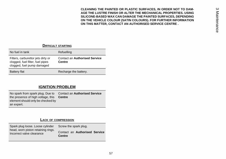
DIFFICULT STARTING
No fuel in tank Refuelling
Filters, carburettor jets dirty orclogged, fuel filter, fuel pipesclogged, fuel pump damaged
Contact an Authorised ServiceCentre
Battery flat Recharge the battery.
IGNITION PROBLEMNo spark from spark plug. Due tothe presence of high voltage, thiselement should only be checked byan expert.
Contact an Authorised ServiceCentre
LACK OF COMPRESSION
Spark plug loose. Loose cylinderhead, worn piston retaining rings.Incorrect valve clearance
Screw the spark plug.
Contact an Authorised ServiceCentre
57
3 Maintenance
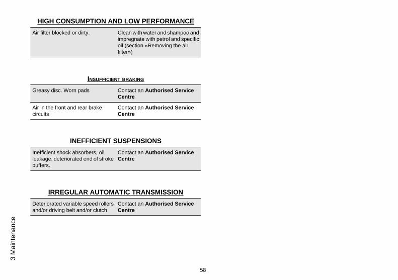
HIGH CONSUMPTION AND LOW PERFORMANCEAir filter blocked or dirty. Clean with water and shampoo and
impregnate with petrol and specificoil (section «Removing the airfilter»)
INSUFFICIENT BRAKING
Greasy disc. Worn pads Contact an Authorised ServiceCentre
Air in the front and rear brakecircuits
Contact an Authorised ServiceCentre
INEFFICIENT SUSPENSIONSInefficient shock absorbers, oilleakage, deteriorated end of strokebuffers.
Contact an Authorised ServiceCentre
IRREGULAR AUTOMATIC TRANSMISSIONDeteriorated variable speed rollersand/or driving belt and/or clutch
Contact an Authorised ServiceCentre
58
3 M
aint
enan
ce
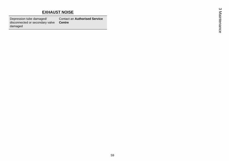
EXHAUST NOISEDepression tube damaged/disconnected or secondary valvedamaged
Contact an Authorised ServiceCentre
59
3 Maintenance

60
3 M
aint
enan
ce

Carnaby es125 - 200
Chap. 04Technical data
61
04_01
62
4 Te
chni
cal d
ata
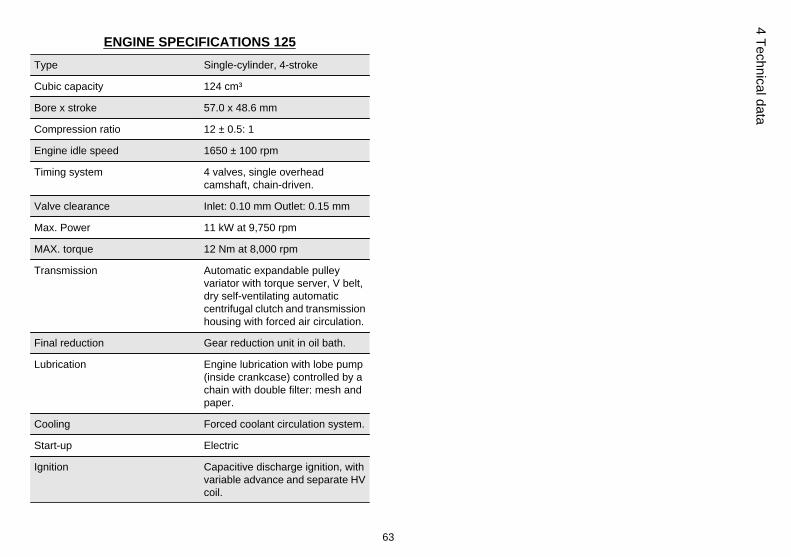
ENGINE SPECIFICATIONS 125Type Single-cylinder, 4-stroke
Cubic capacity 124 cm³
Bore x stroke 57.0 x 48.6 mm
Compression ratio 12 ± 0.5: 1
Engine idle speed 1650 ± 100 rpm
Timing system 4 valves, single overheadcamshaft, chain-driven.
Valve clearance Inlet: 0.10 mm Outlet: 0.15 mm
Max. Power 11 kW at 9,750 rpm
MAX. torque 12 Nm at 8,000 rpm
Transmission Automatic expandable pulleyvariator with torque server, V belt,dry self-ventilating automaticcentrifugal clutch and transmissionhousing with forced air circulation.
Final reduction Gear reduction unit in oil bath.
Lubrication Engine lubrication with lobe pump(inside crankcase) controlled by achain with double filter: mesh andpaper.
Cooling Forced coolant circulation system.
Start-up Electric
Ignition Capacitive discharge ignition, withvariable advance and separate HVcoil.
63
4 Technical data
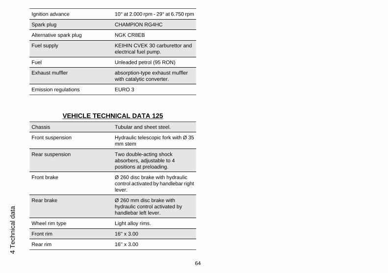
Ignition advance 10° at 2.000 rpm - 29° at 6.750 rpm
Spark plug CHAMPION RG4HC
Alternative spark plug NGK CR8EB
Fuel supply KEIHIN CVEK 30 carburettor andelectrical fuel pump.
Fuel Unleaded petrol (95 RON)
Exhaust muffler absorption-type exhaust mufflerwith catalytic converter.
Emission regulations EURO 3
VEHICLE TECHNICAL DATA 125Chassis Tubular and sheet steel.
Front suspension Hydraulic telescopic fork with Ø 35mm stem
Rear suspension Two double-acting shockabsorbers, adjustable to 4positions at preloading.
Front brake Ø 260 disc brake with hydrauliccontrol activated by handlebar rightlever.
Rear brake Ø 260 mm disc brake withhydraulic control activated byhandlebar left lever.
Wheel rim type Light alloy rims.
Front rim 16'' x 3.00
Rear rim 16'' x 3.00
64
4 Te
chni
cal d
ata
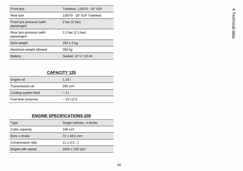
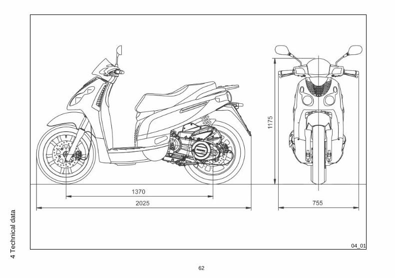
Front tyre Tubeless, 110/70 - 16'' 52P
Rear tyre 130/70 - 16'' 61P Tubeless
Front tyre pressure (withpassenger)
2 bar (2 bar)
Rear tyre pressure (withpassenger)
2.2 bar (2.3 bar)
Kerb weight 154 ± 5 kg
Maximum weight allowed 350 kg
Battery Sealed, 12 V / 10 Ah
CAPACITY 125Engine oil 1.10 l
Transmission oil 250 cm³
Cooling system fluid ~ 2 l
Fuel tank (reserve) ~ 10 l (2 l)
ENGINE SPECIFICATIONS 200Type Single-cylinder, 4-stroke
Cubic capacity 198 cm³
Bore x stroke 72 x 48.6 mm
Compression ratio 11 ± 0.5 : 1
Engine idle speed 1650 ± 100 rpm
65
4 Technical data
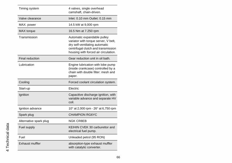
Timing system 4 valves, single overheadcamshaft, chain-driven.
Valve clearance Inlet: 0.10 mm Outlet: 0.15 mm
MAX. power 14.5 kW at 9,000 rpm
MAX torque 16.5 Nm at 7.250 rpm
Transmission Automatic expandable pulleyvariator with torque server, V belt,dry self-ventilating automaticcentrifugal clutch and transmissionhousing with forced air circulation.
Final reduction Gear reduction unit in oil bath.
Lubrication Engine lubrication with lobe pump(inside crankcase) controlled by achain with double filter: mesh andpaper.
Cooling Forced coolant circulation system.
Start-up Electric
Ignition Capacitive discharge ignition, withvariable advance and separate HVcoil.
Ignition advance 10° at 2,000 rpm - 26° at 6,750 rpm
Spark plug CHAMPION RG6YC
Alternative spark plug NGK CR8EB
Fuel supply KEIHIN CVEK 30 carburettor andelectrical fuel pump.
Fuel Unleaded petrol (95 RON)
Exhaust muffler absorption-type exhaust mufflerwith catalytic converter.
66
4 Te
chni
cal d
ata
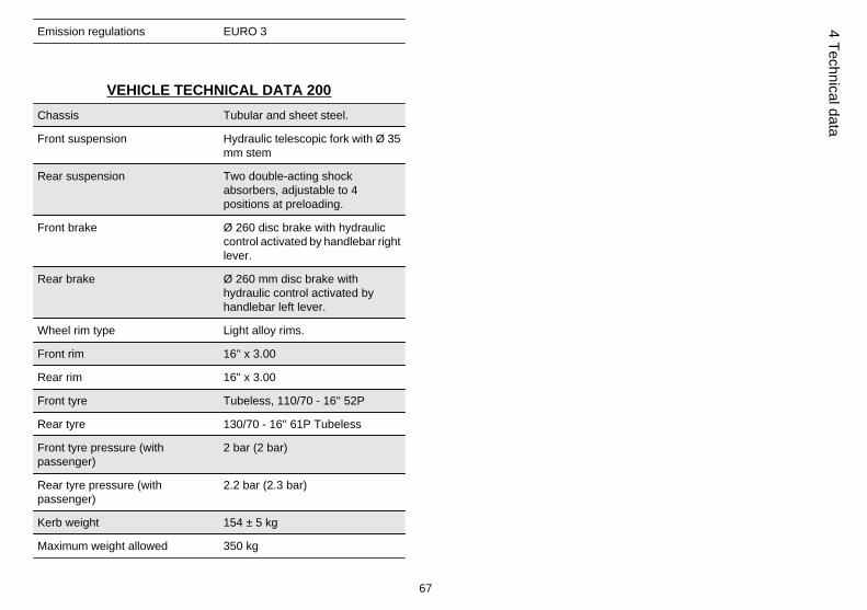
Emission regulations EURO 3
VEHICLE TECHNICAL DATA 200Chassis Tubular and sheet steel.
Front suspension Hydraulic telescopic fork with Ø 35mm stem
Rear suspension Two double-acting shockabsorbers, adjustable to 4positions at preloading.
Front brake Ø 260 disc brake with hydrauliccontrol activated by handlebar rightlever.
Rear brake Ø 260 mm disc brake withhydraulic control activated byhandlebar left lever.
Wheel rim type Light alloy rims.
Front rim 16'' x 3.00
Rear rim 16'' x 3.00
Front tyre Tubeless, 110/70 - 16'' 52P
Rear tyre 130/70 - 16'' 61P Tubeless
Front tyre pressure (withpassenger)
2 bar (2 bar)
Rear tyre pressure (withpassenger)
2.2 bar (2.3 bar)
Kerb weight 154 ± 5 kg
Maximum weight allowed 350 kg
67
4 Technical data
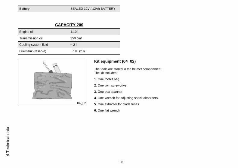
Battery SEALED 12V / 12Ah BATTERY
CAPACITY 200Engine oil 1.10 l
Transmission oil 250 cm³
Cooling system fluid ~ 2 l
Fuel tank (reserve) ~ 10 l (2 l)
04_02
Kit equipment (04_02)
The tools are stored in the helmet compartment.The kit includes:
1. One toolkit bag
2. One twin screwdriver
3. One box-spanner
4. One wrench for adjusting shock absorbers
5. One extractor for blade fuses
6. One flat wrench
68
4 Te
chni
cal d
ata
Carnaby es125 - 200
Chap. 05Spare parts and
accessories
69
05_01
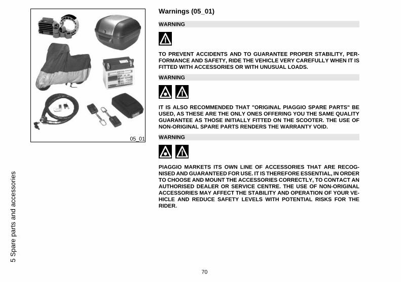
Warnings (05_01)
WARNING
TO PREVENT ACCIDENTS AND TO GUARANTEE PROPER STABILITY, PER-FORMANCE AND SAFETY, RIDE THE VEHICLE VERY CAREFULLY WHEN IT ISFITTED WITH ACCESSORIES OR WITH UNUSUAL LOADS.
WARNING
IT IS ALSO RECOMMENDED THAT "ORIGINAL PIAGGIO SPARE PARTS" BEUSED, AS THESE ARE THE ONLY ONES OFFERING YOU THE SAME QUALITYGUARANTEE AS THOSE INITIALLY FITTED ON THE SCOOTER. THE USE OFNON-ORIGINAL SPARE PARTS RENDERS THE WARRANTY VOID.
WARNING
PIAGGIO MARKETS ITS OWN LINE OF ACCESSORIES THAT ARE RECOG-NISED AND GUARANTEED FOR USE. IT IS THEREFORE ESSENTIAL, IN ORDERTO CHOOSE AND MOUNT THE ACCESSORIES CORRECTLY, TO CONTACT ANAUTHORISED DEALER OR SERVICE CENTRE. THE USE OF NON-ORIGINALACCESSORIES MAY AFFECT THE STABILITY AND OPERATION OF YOUR VE-HICLE AND REDUCE SAFETY LEVELS WITH POTENTIAL RISKS FOR THERIDER.
70
5 Sp
are
parts
and
acc
esso
ries
WARNING
NEVER RIDE THE SCOOTER EQUIPPED WITH ACCESSORIES (TOP BOX AND/OR WINDSHIELD) AT A SPEED HIGHER THAN 100 km/h.
THE SCOOTER CAN BE RIDDEN AT A HIGHER SPEED WITHOUT THE ACCES-SORIES MENTIONED BEFORE WITHIN THE LIMITS ESTABLISHED BY LAW.
IF THERE SHOULD BE NOT-PIAGGIO ACCESSORIES INSTALLED, OR AN AB-NORMAL LOAD, OR IF THE SCOOTER IS NOT IN A GENERALLY GOOD CON-DITION, OR WHENEVER WEATHER CONDITIONS DEMAND IT, SPEED SHOULDBE REDUCED FURTHER.
WARNING
BE EXTREMELY CAREFUL WHEN INSTALLING AND REMOVING THE MECHAN-ICAL ANTITHEFT DEVICE ON THE VEHICLE (U-SHAPED PADLOCK, DISCBLOCK, ETC.).
MAINLY DUE TO THE PROXIMITY TO THE BRAKE PIPES, TRANSMISSIONSAND/OR ELECTRIC CABLES, AN INCORRECT INSTALLATION OR REMOVALOF THE ANTITHEFT DEVICE AS WELL AS LEAVING IT ON BEFORE STARTINGTHE VEHICLE CAN SERIOUSLY DAMAGE ITS COMPONENTS AND AFFECT THECORRECT FUNCTIONING OF THE VEHICLE AND HARM THE USER.
71
5 Spare parts and accessories

72
5 Sp
are
parts
and
acc
esso
ries
Carnaby es125 - 200
Chap. 06Programmedmaintenance
73
Scheduled maintenance table
Adequate maintenance is fundamental to ensuring long-lasting, optimum operationand performance of your scooter.
For this purpose, PIAGGIO offers a set of checks and maintenance services (for pay-ment), which are included in the summary table shown on the following page. Anyminor faults should be reported without delay to an Authorised Service Centre orDealer without waiting until the next scheduled service to solve it.
All scheduled maintenance services must be carried out at the specified times, evenif the stated mileage has not yet been reached. Carrying out scheduled services ontime is necessary to ensure your warranty remains valid. For all other informationconcerning Warranty procedures and "Scheduled Maintenance", please refer to the"Warranty Booklet".
EVERY 2 YEARSCoolant - change
Brake fluid - change
EVERY 3,000 KMEngine oil - level check/ top-up
AFTER 1,000 KM
Engine oil - replacement
Hub oil - change
Engine oil - change
74
6 Pr
ogra
mm
ed m
aint
enan
ce
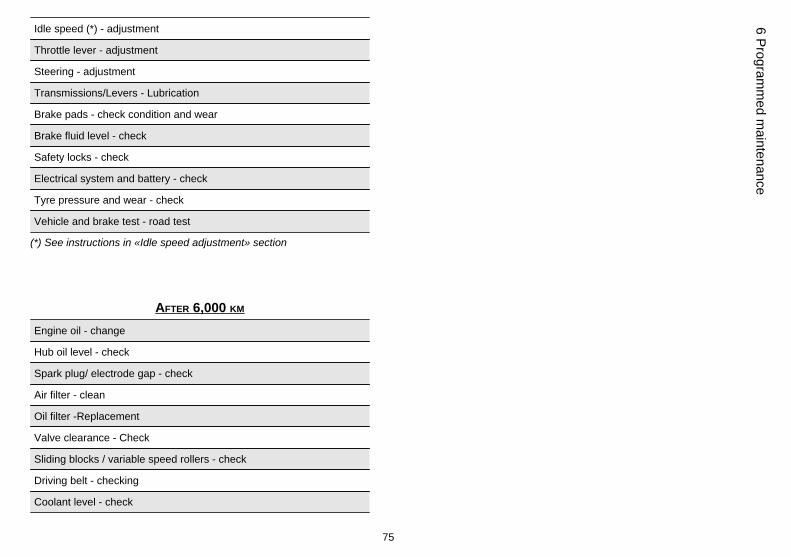
Idle speed (*) - adjustment
Throttle lever - adjustment
Steering - adjustment
Transmissions/Levers - Lubrication
Brake pads - check condition and wear
Brake fluid level - check
Safety locks - check
Electrical system and battery - check
Tyre pressure and wear - check
Vehicle and brake test - road test
(*) See instructions in «Idle speed adjustment» section
AFTER 6,000 KM
Engine oil - change
Hub oil level - check
Spark plug/ electrode gap - check
Air filter - clean
Oil filter -Replacement
Valve clearance - Check
Sliding blocks / variable speed rollers - check
Driving belt - checking
Coolant level - check
75
6 Programm
ed maintenance
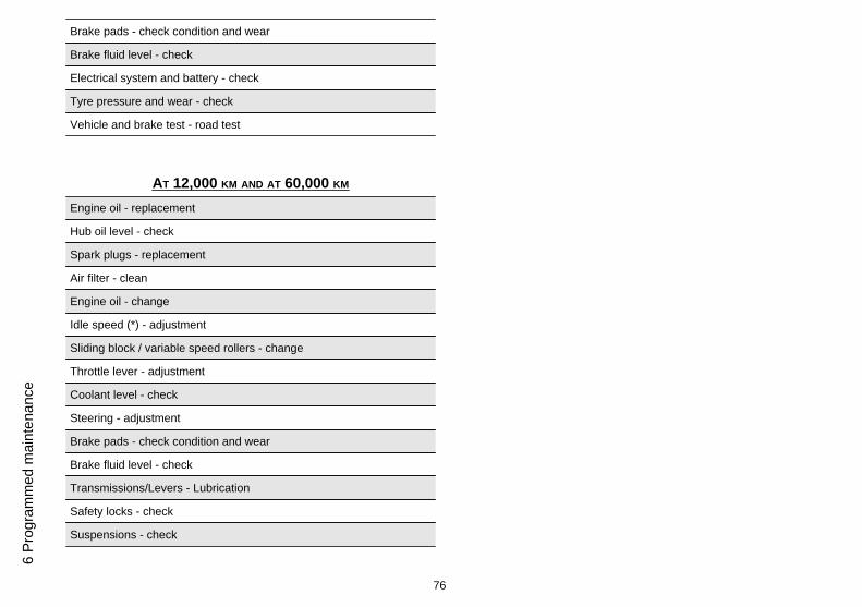
Brake pads - check condition and wear
Brake fluid level - check
Electrical system and battery - check
Tyre pressure and wear - check
Vehicle and brake test - road test
AT 12,000 KM AND AT 60,000 KM
Engine oil - replacement
Hub oil level - check
Spark plugs - replacement
Air filter - clean
Engine oil - change
Idle speed (*) - adjustment
Sliding block / variable speed rollers - change
Throttle lever - adjustment
Coolant level - check
Steering - adjustment
Brake pads - check condition and wear
Brake fluid level - check
Transmissions/Levers - Lubrication
Safety locks - check
Suspensions - check
76
6 Pr
ogra
mm
ed m
aint
enan
ce
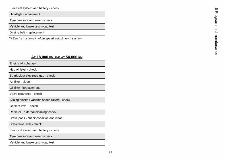
Electrical system and battery - check
Headlight - adjustment
Tyre pressure and wear - check
Vehicle and brake test - road test
Driving belt - replacement
(*) See instructions in «Idle speed adjustment» section
AT 18,000 KM AND AT 54,000 KM
Engine oil - change
Hub oil level - check
Spark plug/ electrode gap - check
Air filter - clean
Oil filter -Replacement
Valve clearance - check
Sliding blocks / variable speed rollers - check
Coolant level - check
Radiator - external cleaning/ check
Brake pads - check condition and wear
Brake fluid level - check
Electrical system and battery - check
Tyre pressure and wear - check
Vehicle and brake test - road test
77
6 Programm
ed maintenance
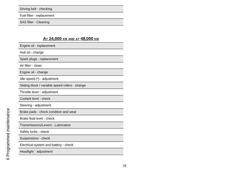
Driving belt - checking
Fuel filter - replacement
SAS filter - Cleaning
AT 24,000 KM AND AT 48,000 KM
Engine oil - replacement
Hub oil - change
Spark plugs - replacement
Air filter - clean
Engine oil - change
Idle speed (*) - adjustment
Sliding block / variable speed rollers - change
Throttle lever - adjustment
Coolant level - check
Steering - adjustment
Brake pads - check condition and wear
Brake fluid level - check
Transmissions/Levers - Lubrication
Safety locks - check
Suspensions - check
Electrical system and battery - check
Headlight - adjustment
78
6 Pr
ogra
mm
ed m
aint
enan
ce
Tyre pressure and wear - check
Vehicle and brake test - road test
Driving Belt - replacement
(*) See instructions in «Idle speed adjustment» section
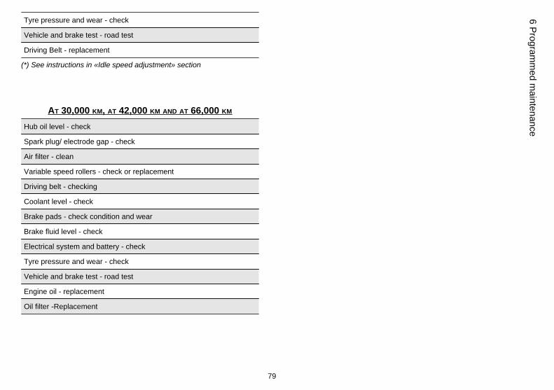
AT 30,000 KM, AT 42,000 KM AND AT 66,000 KM
Hub oil level - check
Spark plug/ electrode gap - check
Air filter - clean
Variable speed rollers - check or replacement
Driving belt - checking
Coolant level - check
Brake pads - check condition and wear
Brake fluid level - check
Electrical system and battery - check
Tyre pressure and wear - check
Vehicle and brake test - road test
Engine oil - replacement
Oil filter -Replacement
79
6 Programm
ed maintenance
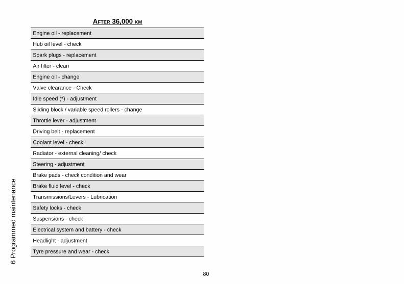
AFTER 36,000 KM
Engine oil - replacement
Hub oil level - check
Spark plugs - replacement
Air filter - clean
Engine oil - change
Valve clearance - Check
Idle speed (*) - adjustment
Sliding block / variable speed rollers - change
Throttle lever - adjustment
Driving belt - replacement
Coolant level - check
Radiator - external cleaning/ check
Steering - adjustment
Brake pads - check condition and wear
Brake fluid level - check
Transmissions/Levers - Lubrication
Safety locks - check
Suspensions - check
Electrical system and battery - check
Headlight - adjustment
Tyre pressure and wear - check
80
6 Pr
ogra
mm
ed m
aint
enan
ce
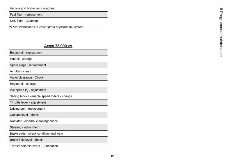
Vehicle and brake test - road test
Fuel filter - replacement
SAS filter - Cleaning
(*) See instructions in «Idle speed adjustment» section
AFTER 72,000 KM
Engine oil - replacement
Hub oil - change
Spark plugs - replacement
Air filter - clean
Valve clearance - Check
Engine oil - change
Idle speed (*) - adjustment
Sliding block / variable speed rollers - change
Throttle lever - adjustment
Driving belt - replacement
Coolant level - check
Radiator - external cleaning/ check
Steering - adjustment
Brake pads - check condition and wear
Brake fluid level - check
Transmissions/Levers - Lubrication
81
6 Programm
ed maintenance
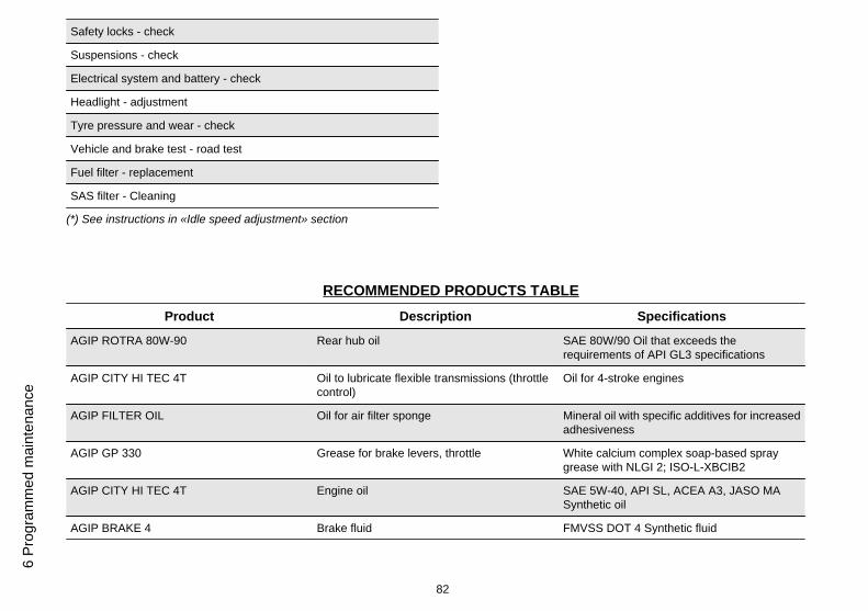
Safety locks - check
Suspensions - check
Electrical system and battery - check
Headlight - adjustment
Tyre pressure and wear - check
Vehicle and brake test - road test
Fuel filter - replacement
SAS filter - Cleaning
(*) See instructions in «Idle speed adjustment» section
RECOMMENDED PRODUCTS TABLEProduct Description Specifications
AGIP ROTRA 80W-90 Rear hub oil SAE 80W/90 Oil that exceeds therequirements of API GL3 specifications
AGIP CITY HI TEC 4T Oil to lubricate flexible transmissions (throttlecontrol)
Oil for 4-stroke engines
AGIP FILTER OIL Oil for air filter sponge Mineral oil with specific additives for increasedadhesiveness
AGIP GP 330 Grease for brake levers, throttle White calcium complex soap-based spraygrease with NLGI 2; ISO-L-XBCIB2
AGIP CITY HI TEC 4T Engine oil SAE 5W-40, API SL, ACEA A3, JASO MASynthetic oil
AGIP BRAKE 4 Brake fluid FMVSS DOT 4 Synthetic fluid
82
6 Pr
ogra
mm
ed m
aint
enan
ce
Product Description Specifications
SPECIAL AGIP PERMANENT fluid coolant Monoethylene glycol-based antifreeze fluid,CUNA NC 956-16
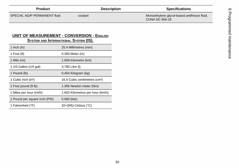
UNIT OF MEASUREMENT - CONVERSION - ENGLISHSYSTEM AND INTERNATIONAL SYSTEM (IS).
1 Inch (in) 25.4 Millimetres (mm)
1 Foot (ft) 0.305 Meter (m)
1 Mile (mi) 1.609 Kilometre (km)
1 US Gallon (US gal) 3.785 Litre (l)
1 Pound (lb) 0.454 Kilogram (kg)
1 Cubic inch (in³) 16.4 Cubic centimetres (cm³)
1 Foot pound (ft lb) 1.356 Newton meter (Nm)
1 Miles per hour (mi/h) 1.602 Kilometres per hour (km/h)
1 Pound per square inch (PSI) 0.069 (bar)
1 Fahrenheit (°F) 32+(9/5) Celsius (°C)
83
6 Programm
ed maintenance

84
6 Pr
ogra
mm
ed m
aint
enan
ce
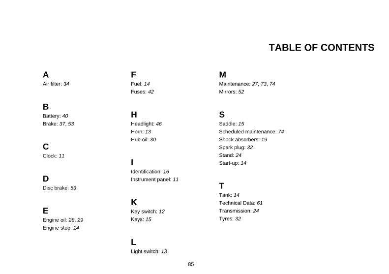
TABLE OF CONTENTS
AAir filter: 34
BBattery: 40Brake: 37, 53
CClock: 11
DDisc brake: 53
EEngine oil: 28, 29Engine stop: 14
FFuel: 14Fuses: 42
HHeadlight: 46Horn: 13Hub oil: 30
IIdentification: 16Instrument panel: 11
KKey switch: 12Keys: 15
LLight switch: 13
MMaintenance: 27, 73, 74Mirrors: 52
SSaddle: 15Scheduled maintenance: 74Shock absorbers: 19Spark plug: 32Stand: 24Start-up: 14
TTank: 14Technical Data: 61Transmission: 24Tyres: 32
85

The descriptions and illustrations given in this publication are not binding. While the basic features as described and illustrated in this manual remainunchanged, PIAGGIO - GILERA reserves the right, at any time and without being required to update this publication beforehand, to make any changesto components, parts or accessory supplies, which it considers necessary to improve the product or which are required for manufacturing or constructionreasons.
Not all versions shown in this publication are available in all Countries. The availability of individual versions should be confirmed with the official Piaggio sales network.
"© Copyright 2007 - PIAGGIO & C. S.p.A. Pontedera. All rights reserved. Reproduction of this publication in whole or in part is prohibited."
PIAGGIO & C. S.p.A. - After-Sales
V.le Rinaldo Piaggio, 23 - 56025 PONTEDERA (Pi)