Embed Size (px)
Citation preview
PIAGGIO WOULD LIKE TO THANK YOU
for choosing one of its products. We have prepared this manual to help you to get the very best from your vehicle. Please read it carefully before ridingthe vehicle for the first time. It contains information, tips and precautions for using your vehicle. It also describes features, details and devices to assureyou that you have made the right choice. We believe that if you follow our suggestions, you will soon get to know your new scooter and it will serve youwell for a long time to come. This booklet forms an integral part of the vehicle; should the vehicle be sold, it must be transferred to the new owner.
Liberty 125-150
Ed. 02_02/2013
The instructions given in this manual are intended to provide a clear, simple guide to using your vehicle; this booklet also details routine maintenanceprocedures and regular checks that should be carried out on the vehicle at an authorised Dealer or Service Centre. The booklet also containsinstructions for simple repairs. Any operations not specifically described in this booklet require the use of special tools and/or particular technicalknowledge: to carry out these operations, refer to any authorised Dealer or Service Centres.
2
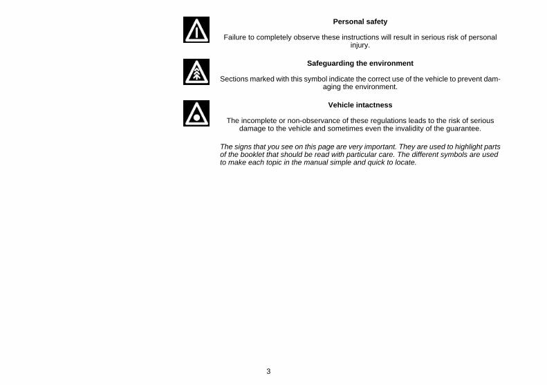
Personal safety
Failure to completely observe these instructions will result in serious risk of personalinjury.
Safeguarding the environment
Sections marked with this symbol indicate the correct use of the vehicle to prevent dam-aging the environment.
Vehicle intactness
The incomplete or non-observance of these regulations leads to the risk of seriousdamage to the vehicle and sometimes even the invalidity of the guarantee.
The signs that you see on this page are very important. They are used to highlight partsof the booklet that should be read with particular care. The different symbols are usedto make each topic in the manual simple and quick to locate.
3

4
INDEX
VEHICLE...................................................................................... 7Dashboard................................................................................ 8Clock......................................................................................... 9Keyswitch.................................................................................. 10
Locking the steering wheel.................................................... 10Releasing the steering wheel................................................ 11
Switch direction indicators........................................................ 11Horn button............................................................................... 12Light switch............................................................................... 12Start-up button.......................................................................... 13
Opening the saddle............................................................... 13Identification.............................................................................. 14Rear top box opening................................................................ 14Bag clip..................................................................................... 15
USE.............................................................................................. 17Checks...................................................................................... 18Refuelling.................................................................................. 18Tyre pressure............................................................................ 19Shock absorbers adjustment.................................................... 20Running in................................................................................. 21Starting up the engine............................................................... 21
Precautions........................................................................... 22Difficult start up......................................................................... 23Stopping the engine.................................................................. 24Automatic transmission............................................................. 24Safe driving............................................................................... 25
MAINTENANCE........................................................................... 27Engine oil level.......................................................................... 28
Engine oil level check............................................................ 28Engine oil top-up................................................................... 29Warning light (insufficient oil pressure)................................. 30Engine oil change.................................................................. 30
Hub oil level.............................................................................. 31
Tyres......................................................................................... 33Spark plug dismantlement........................................................ 34Removing the air filter............................................................... 35Secondary air system............................................................... 35Checking the brake oil level...................................................... 36
Braking system fluid top up................................................... 38Battery....................................................................................... 39Long periods of inactivity.......................................................... 40Fuses........................................................................................ 41Front light group........................................................................ 45
Head light adjustment............................................................ 47Front direction indicators........................................................... 48Rear optical unit........................................................................ 48Rear-view mirrors...................................................................... 50Idle adjustment.......................................................................... 50Front disc brake........................................................................ 51Rear drum brake....................................................................... 52Puncture.................................................................................... 52Inactivity of the vehicle.............................................................. 52Cleaning the vehicle.................................................................. 53
TECHNICAL DATA...................................................................... 59Tool kit...................................................................................... 65
SPARE PARTS AND ACCESSORIES........................................ 67Warnings................................................................................... 68
SCHEDULED MAINTENANCE.................................................... 69Scheduled servicing table......................................................... 70
5

6
Liberty 125-150
Chap. 01Vehicle
7
01_01
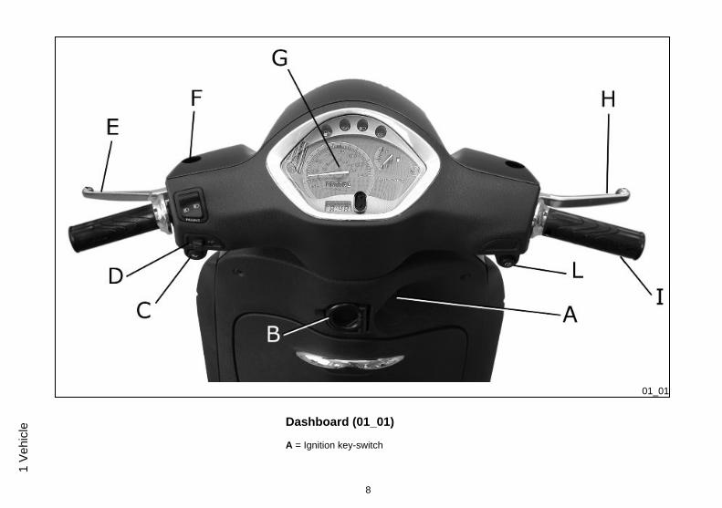
Dashboard (01_01)
A = Ignition key-switch
8
1 Ve
hicl
e

B = Bag hook
C = Horn button
D = Turn indicator switch
E = Rear brake lever
F = Headlight switch
G = Analogue instrument panel
H = Front brake lever
I = Throttle grip
L = Starter button
01_02
Clock (01_02, 01_03)
Hours and minutes are displayed in a 1 to 12, AM or PM, format on the instrumentpanel.Operating the function selection switch «T» month, day and seconds can be seenbesides hours and minutes. In order to adjust the above mentioned functions, operatebutton «U». The digital clock is powered by a battery (battery life is about 2 years); liftthe whole instrument panel to replace the battery. It is advisable to take your vehicleto an Authorised Service Centre for this operation.
WARNING
DEAD BATTERIES ARE HARMFUL TO THE ENVIRONMENT. THEY MUST DIS-POSED OF IN SUITABLE CONTAINERS AS PRESCRIBED BY THE REGULA-TIONS IN FORCE.
9
1 Vehicle

01_03
01_04
Keyswitch (01_04)
SWITCH POSITIONS
ON«1»: Ready to start position, non-extractable key, mechanical antitheft device dis-abled.
OFF «2»: Ignition disabled, extractable key, mechanical antitheft device disabled.
LOCK «3»: Ignition disabled, extractable key, mechanical antitheft device enabled.
Locking the steering wheel
Turn the handlebar to the left (as far as it will go), turn the key to «LOCK» and removethe key.
CAUTION
NEVER TURN THE KEY TO «LOCK» OR «OFF» WHILE RIDING.
10
1 Ve
hicl
e

Releasing the steering wheel
Reinsert the key and turn it to «OFF».
CAUTION
NEVER TURN THE KEY TO «LOCK» OR «OFF» WHILE RIDING.
01_05
Switch direction indicators (01_05)
To set the left turn indicators flashing, move lever «B» to the left; to set the right turnindicators flashing, move it to the right. The lever automatically returns to the centralposition and the indicators remain on. To turn the indicators off, press the lever towardsthe switch.
11
1 Vehicle

01_06
Horn button (01_06)
Horn button «E»
Light switch (01_07)
0 = Low-beam and taillight
1 = High-beam and taillight
2 = High-beam flash (passing)
01_07
CAUTION
DO NOT PLACE, TRANSPORT OBJECTS AND/OR CLOTHES OVER THE FRONTHEADLIGHT ASSEMBLY, WHEN THE HEADLIGHT IS TURNED ON OR OFF.FAILURE TO FOLLOW THIS PRECAUTION MAY CAUSE OVERHEATING ANDTHE SUBSEQUENT FUSION OF THE GLASS.
12
1 Ve
hicl
e
01_08
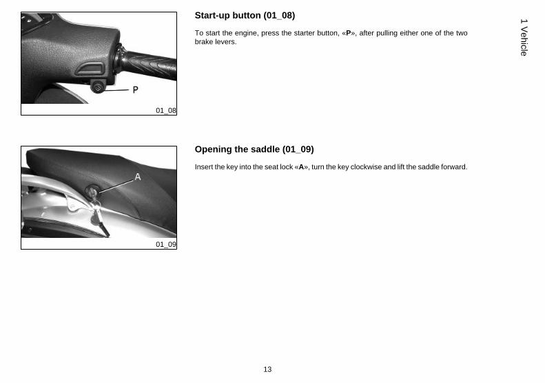
Start-up button (01_08)
To start the engine, press the starter button, «P», after pulling either one of the twobrake levers.
01_09
Opening the saddle (01_09)
Insert the key into the seat lock «A», turn the key clockwise and lift the saddle forward.
13
1 Vehicle
01_10
01_11
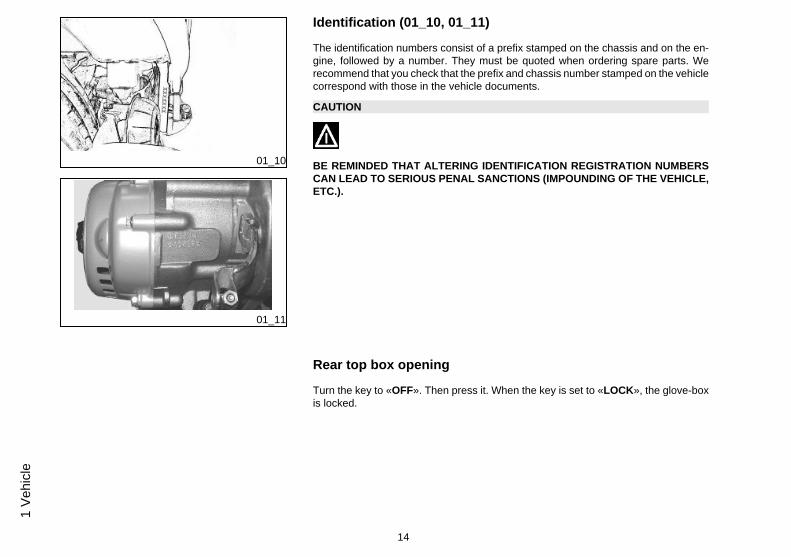
Identification (01_10, 01_11)
The identification numbers consist of a prefix stamped on the chassis and on the en-gine, followed by a number. They must be quoted when ordering spare parts. Werecommend that you check that the prefix and chassis number stamped on the vehiclecorrespond with those in the vehicle documents.
CAUTION
BE REMINDED THAT ALTERING IDENTIFICATION REGISTRATION NUMBERSCAN LEAD TO SERIOUS PENAL SANCTIONS (IMPOUNDING OF THE VEHICLE,ETC.).
Rear top box opening
Turn the key to «OFF». Then press it. When the key is set to «LOCK», the glove-boxis locked.
14
1 Ve
hicl
e
01_12
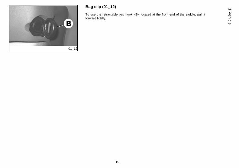
Bag clip (01_12)
To use the retractable bag hook «B» located at the front end of the saddle, pull itforward lightly.
15
1 Vehicle

16
1 Ve
hicl
e

Liberty 125-150
Chap. 02Use
17
Checks
Before using the vehicle, check:
1. That the fuel tank is full.
2. Rear hub oil level.
3. Engine oil level (see the «Engine oil level» section).
4. That the tyres are properly inflated.
5. The correct functioning of headlights, rear light and turn indicators.
6. The correct functioning of front and rear brakes.
02_01
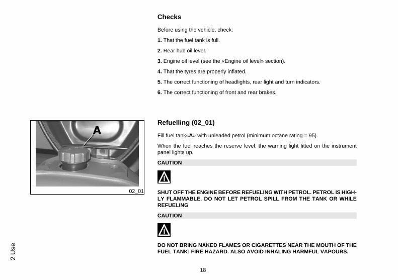
Refuelling (02_01)
Fill fuel tank«A» with unleaded petrol (minimum octane rating = 95).
When the fuel reaches the reserve level, the warning light fitted on the instrumentpanel lights up.
CAUTION
SHUT OFF THE ENGINE BEFORE REFUELING WITH PETROL. PETROL IS HIGH-LY FLAMMABLE. DO NOT LET PETROL SPILL FROM THE TANK OR WHILEREFUELING
CAUTION
DO NOT BRING NAKED FLAMES OR CIGARETTES NEAR THE MOUTH OF THEFUEL TANK: FIRE HAZARD. ALSO AVOID INHALING HARMFUL VAPOURS.
18
2 U
se
CAUTION
USING OILS OTHER THAN THOSE RECOMMENDED CAN SHORTEN THE LIFEOF THE ENGINE.
CharacteristicFuel tank capacity
about 7 litres (1.5 l of which is reserve)
02_02
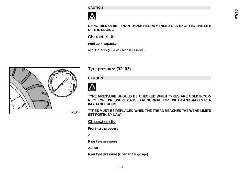
Tyre pressure (02_02)
CAUTION
TYRE PRESSURE SHOULD BE CHECKED WHEN TYRES ARE COLD.INCOR-RECT TYRE PRESSURE CAUSES ABNORMAL TYRE WEAR AND MAKES RID-ING DANGEROUS.
TYRES MUST BE REPLACED WHEN THE TREAD REACHES THE WEAR LIMITSSET FORTH BY LAW.
CharacteristicFront tyre pressure
2 bar
Rear tyre pressure
2.2 bar
Rear tyre pressure (rider and luggage)
19
2 Use

2.5 bar
TYRESFront tyre Tubeless, 90/80 - 16" 51J
Rear tyre Tubeless, 110/80 - 14" 59J
02_03
Shock absorbers adjustment (02_03)
The preloading of the springs can be adjusted to 4 positions acting on the ring nutlocated in the lower part of the shock absorbers with the specific spanner supplied.
Position 1: minimum preload: rider only
Position 2 medium preloading: rider only
Position 3 medium preloading: rider and passenger
Position 4: maximum preloading: rider, passenger, and luggage.
In order to carry out this operation you will need to use the specific spanner in the kit.
CAUTION
RIDING THE VEHICLE WITH THE SPRING PRELOADING NOT CORRECTLY SETFOR THE RIDER AND POSSIBLE PASSENGER, COULD REDUCE THE COM-FORT OF THE RIDE AND THE PRECISION OF THE STEERING.
20
2 U
se
WARNING
WE RECOMMEND WEARING GLOVES WHILE CARRYING OUT THIS OPERA-TION IN ORDER TO AVOID INJURIES.
02_04
Running in (02_04)
WARNING
DURING THE FIRST 1000 KM DO NOT RIDE THE VEHICLE OVER 80% OF ITSMAXIMUM SPEED. AVOID TWISTING THE THROTTLE GRIP FULLY OR KEEP-ING A CONSTANT SPEED ALONG LONG SECTIONS OF ROAD. AFTER THEFIRST 1000 KM, GRADUALLY INCREASE SPEED UNTIL REACHING THE MAX-IMUM PERFORMANCE.
02_05
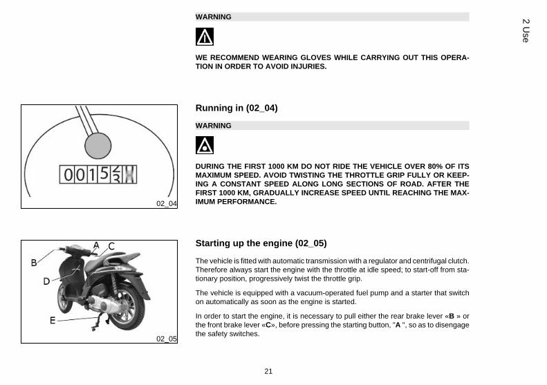
Starting up the engine (02_05)
The vehicle is fitted with automatic transmission with a regulator and centrifugal clutch.Therefore always start the engine with the throttle at idle speed; to start-off from sta-tionary position, progressively twist the throttle grip.
The vehicle is equipped with a vacuum-operated fuel pump and a starter that switchon automatically as soon as the engine is started.
In order to start the engine, it is necessary to pull either the rear brake lever «B » orthe front brake lever «C», before pressing the starting button, "A ", so as to disengagethe safety switches.
21
2 Use
1: Put the scooter on its stand "E"; check that the rear wheel is off the ground.
2: Keep the throttle closed.
3: Insert the key into the ignition switch, "D", and turn to the ON position.
4: Push the starter button «A» after pulling the rear brake lever «B» or the front brakelever «C».
CAUTION
DO NOT CARRY OUT THESE OPERATIONS IN CLOSED AREAS SINCE EX-HAUST GASES ARE TOXIC.
CAUTION
DUE TO THE HIGH TEMPERATURES THE CATALYTIC CONVERTER CANREACH, ALWAYS TAKE CARE, WHEN PARKING THE VEHICLE, THAT THE SI-LENCER DOES NOT COME INTO CONTACT WITH FLAMMABLE MATERIALS,TO AVOID SERIOUS BURNS.
Precautions
CAUTION
NEVER STRESS THE ENGINE AT LOW TEMPERATURES IN ORDER TO AVOIDPOSSIBLE DAMAGE. BE CAREFUL NEVER TO EXCEED THE MAXIMUM SPEEDWHILE RUNNING DOWNHILL, IN ORDER TO AVOID DAMAGING THE ENGINE.IN ANY CASE, IN ORDER TO PRESERVE THE ENGINE FROM PROLONGED
22
2 U
se
OVERREVVING, THE REVOLUTION LIMITER WILL BE ACTIVATED IF THE EN-GINE SPEED EXCEEDS THE ESTABLISHED THRESHOLD.
WARNING
AFTER A LONG DISTANCE COVERED AT THE MAXIMUM SPEED, DO NOT STOPTHE ENGINE IMMEDIATELY, BUT LET IT RUN AT IDLE FOR A FEW SECONDS.
02_06
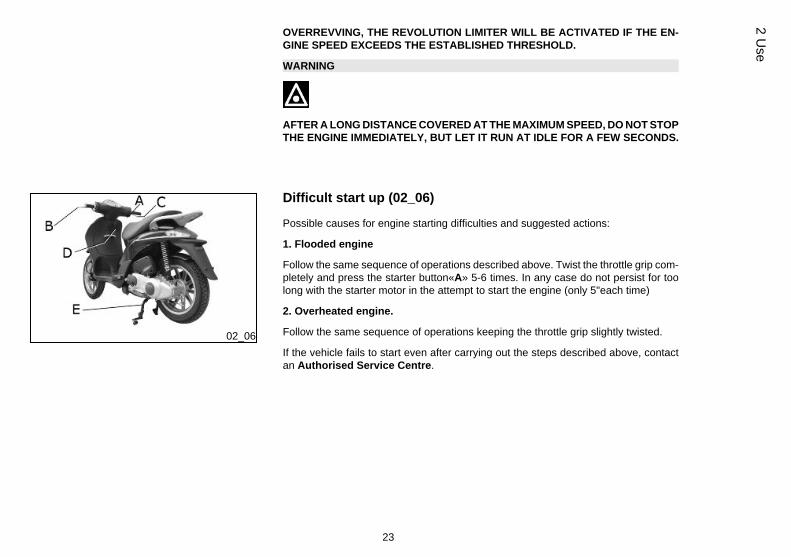
Difficult start up (02_06)
Possible causes for engine starting difficulties and suggested actions:
1. Flooded engine
Follow the same sequence of operations described above. Twist the throttle grip com-pletely and press the starter button«A» 5-6 times. In any case do not persist for toolong with the starter motor in the attempt to start the engine (only 5"each time)
2. Overheated engine.
Follow the same sequence of operations keeping the throttle grip slightly twisted.
If the vehicle fails to start even after carrying out the steps described above, contactan Authorised Service Centre.
23
2 Use
02_07
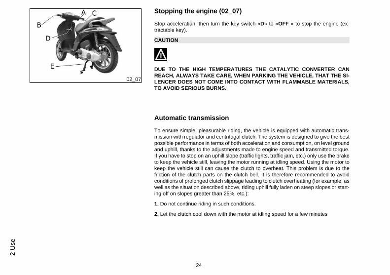
Stopping the engine (02_07)
Stop acceleration, then turn the key switch «D» to «OFF » to stop the engine (ex-tractable key).
CAUTION
DUE TO THE HIGH TEMPERATURES THE CATALYTIC CONVERTER CANREACH, ALWAYS TAKE CARE, WHEN PARKING THE VEHICLE, THAT THE SI-LENCER DOES NOT COME INTO CONTACT WITH FLAMMABLE MATERIALS,TO AVOID SERIOUS BURNS.
Automatic transmission
To ensure simple, pleasurable riding, the vehicle is equipped with automatic trans-mission with regulator and centrifugal clutch. The system is designed to give the bestpossible performance in terms of both acceleration and consumption, on level groundand uphill, thanks to the adjustments made to engine speed and transmitted torque.If you have to stop on an uphill slope (traffic lights, traffic jam, etc.) only use the braketo keep the vehicle still, leaving the motor running at idling speed. Using the motor tokeep the vehicle still can cause the clutch to overheat. This problem is due to thefriction of the clutch parts on the clutch bell. It is therefore recommended to avoidconditions of prolonged clutch slippage leading to clutch overheating (for example, aswell as the situation described above, riding uphill fully laden on steep slopes or start-ing off on slopes greater than 25%, etc.):
1. Do not continue riding in such conditions.
2. Let the clutch cool down with the motor at idling speed for a few minutes
24
2 U
se
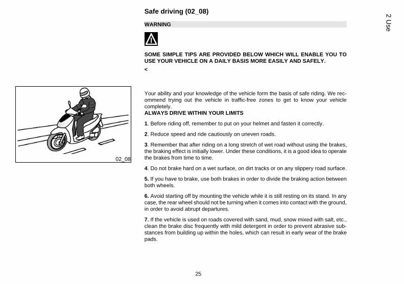
Safe driving (02_08)
WARNING
SOME SIMPLE TIPS ARE PROVIDED BELOW WHICH WILL ENABLE YOU TOUSE YOUR VEHICLE ON A DAILY BASIS MORE EASILY AND SAFELY.<
02_08
Your ability and your knowledge of the vehicle form the basis of safe riding. We rec-ommend trying out the vehicle in traffic-free zones to get to know your vehiclecompletely.ALWAYS DRIVE WITHIN YOUR LIMITS
1. Before riding off, remember to put on your helmet and fasten it correctly.
2. Reduce speed and ride cautiously on uneven roads.
3. Remember that after riding on a long stretch of wet road without using the brakes,the braking effect is initially lower. Under these conditions, it is a good idea to operatethe brakes from time to time.
4. Do not brake hard on a wet surface, on dirt tracks or on any slippery road surface.
5. If you have to brake, use both brakes in order to divide the braking action betweenboth wheels.
6. Avoid starting off by mounting the vehicle while it is still resting on its stand. In anycase, the rear wheel should not be turning when it comes into contact with the ground,in order to avoid abrupt departures.
7. If the vehicle is used on roads covered with sand, mud, snow mixed with salt, etc.,clean the brake disc frequently with mild detergent in order to prevent abrasive sub-stances from building up within the holes, which can result in early wear of the brakepads.
25
2 Use
8. Any elaboration that modifies the vehicle's performances, such as tampering withoriginal structural parts is strictly forbidden by law, and renders the vehicle not con-forming to the approved type and therefor dangerous to ride.
CAUTION
RIDING UNDER THE INFLUENCE OF ALCOHOL, DRUGS OR CERTAIN MEDI-CINES CAN BE EXTREMELY DANGEROUS FOR ONESELF AND FOR OTHERS.
CAUTION
ANY ELABORATION THAT MODIFIES THE VEHICLE'S PERFORMANCES, SUCHAS TAMPERING WITH ORIGINAL STRUCTURAL PARTS IS STRICTLY FORBID-DEN BY LAW, AND RENDERS THE VEHICLE NO LONGER CONFORMING TOTHE APPROVED TYPE AND DANGEROUS FOR RIDING.
26
2 U
se

Liberty 125-150
Chap. 03Maintenance
27
03_01
03_02
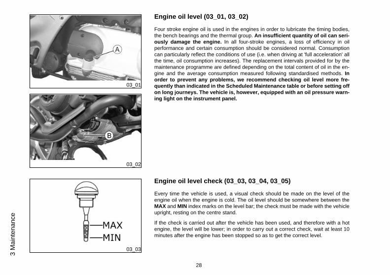
Engine oil level (03_01, 03_02)
Four stroke engine oil is used in the engines in order to lubricate the timing bodies,the bench bearings and the thermal group. An insufficient quantity of oil can seri-ously damage the engine. In all four-stroke engines, a loss of efficiency in oilperformance and certain consumption should be considered normal. Consumptioncan particularly reflect the conditions of use (i.e. when driving at 'full acceleration' allthe time, oil consumption increases). The replacement intervals provided for by themaintenance programme are defined depending on the total content of oil in the en-gine and the average consumption measured following standardised methods. Inorder to prevent any problems, we recommend checking oil level more fre-quently than indicated in the Scheduled Maintenance table or before setting offon long journeys. The vehicle is, however, equipped with an oil pressure warn-ing light on the instrument panel.
03_03
Engine oil level check (03_03, 03_04, 03_05)
Every time the vehicle is used, a visual check should be made on the level of theengine oil when the engine is cold. The oil level should be somewhere between theMAX and MIN index marks on the level bar; the check must be made with the vehicleupright, resting on the centre stand.
If the check is carried out after the vehicle has been used, and therefore with a hotengine, the level will be lower; in order to carry out a correct check, wait at least 10minutes after the engine has been stopped so as to get the correct level.
28
3 M
aint
enan
ce

03_04
03_05
CAUTION
RUNNING THE ENGINE WITH INSUFFICIENT LUBRICATION OR WITH THE IN-ADEQUATE LUBRICANTS ACCELERATES WEAR AND TEAR OF THE MOVINGPARTS AND CAN CAUSE IRRETRIEVABLE DAMAGE.
CharacteristicEngine oil
1100 cm³
Engine oil top-up
Always check oil level before carrying out top-ups and add oil without exceeding theMAX level. An engine oil check-up and top-up should be carried out every 3,000 kmat an Authorised Piaggio Service Centre.
29
3 Maintenance

03_06
03_07
Warning light (insufficient oil pressure) (03_06, 03_07)
The vehicle is equipped with a warning light that comes on when the key is turned to«ON». However, this light should switch off once the engine has been started. If thelight comes on while braking, at idle speed or while turning a corner, it is nec-essary to check the oil level and top it up if required. If after having topped-upthe oil, the warning light still comes on while braking, at idle speed or whileturning a corner, it will be necessary to take your vehicle to an Authorised Serv-ice Centre.
03_08
Engine oil change (03_08, 03_09)
Oil must be changed and filter replaced at an Authorised Service Centre (as indi-cated in the Scheduled Maintenance Table). The engine should be emptied bydraining the oil through drainage plug «B » of the mesh filter on the flywheel side. Inorder to facilitate oil drainage, loosen the cap/dipstick «A». Since a certain quantity ofoil remains in the circuit still, the top-up should be carried out from the cap«A».
Then start up the vehicle, leave it running for a few minutes and switch it off: afterabout five minutes check the level and if necessary top up without exceeding theMAX level.
The cartridge filter must be replaced every time the oil is changed. For top-ups andchanges use new oil of the recommended type.
30
3 M
aint
enan
ce
03_09
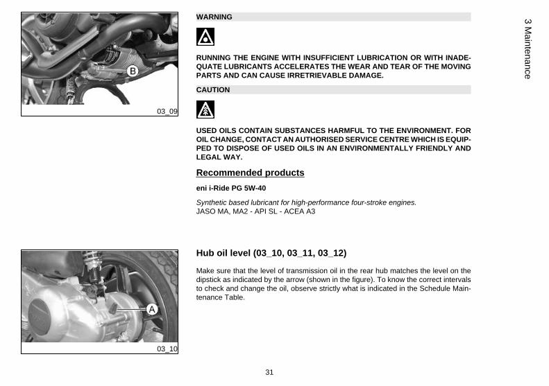
WARNING
RUNNING THE ENGINE WITH INSUFFICIENT LUBRICATION OR WITH INADE-QUATE LUBRICANTS ACCELERATES THE WEAR AND TEAR OF THE MOVINGPARTS AND CAN CAUSE IRRETRIEVABLE DAMAGE.
CAUTION
USED OILS CONTAIN SUBSTANCES HARMFUL TO THE ENVIRONMENT. FOROIL CHANGE, CONTACT AN AUTHORISED SERVICE CENTRE WHICH IS EQUIP-PED TO DISPOSE OF USED OILS IN AN ENVIRONMENTALLY FRIENDLY ANDLEGAL WAY.
Recommended productseni i-Ride PG 5W-40
Synthetic based lubricant for high-performance four-stroke engines.JASO MA, MA2 - API SL - ACEA A3
03_10
Hub oil level (03_10, 03_11, 03_12)
Make sure that the level of transmission oil in the rear hub matches the level on thedipstick as indicated by the arrow (shown in the figure). To know the correct intervalsto check and change the oil, observe strictly what is indicated in the Schedule Main-tenance Table.
31
3 Maintenance
03_11
03_12
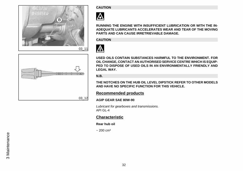
CAUTION
RUNNING THE ENGINE WITH INSUFFICIENT LUBRICATION OR WITH THE IN-ADEQUATE LUBRICANTS ACCELERATES WEAR AND TEAR OF THE MOVINGPARTS AND CAN CAUSE IRRETRIEVABLE DAMAGE.
CAUTION
USED OILS CONTAIN SUBSTANCES HARMFUL TO THE ENVIRONMENT. FOROIL CHANGE, CONTACT AN AUTHORISED SERVICE CENTRE WHICH IS EQUIP-PED TO DISPOSE OF USED OILS IN AN ENVIRONMENTALLY FRIENDLY ANDLEGAL WAY.
N.B.
THE NOTCHES ON THE HUB OIL LEVEL DIPSTICK REFER TO OTHER MODELSAND HAVE NO SPECIFIC FUNCTION FOR THIS VEHICLE.
Recommended productsAGIP GEAR SAE 80W-90
Lubricant for gearboxes and transmissions.API GL-4
CharacteristicRear hub oil
~ 200 cm³
32
3 M
aint
enan
ce

03_13
Tyres (03_13)
Periodically check the inflation pressure of each tyre. Tyres are equipped with wearindicators. Tyres should be replaced as soon as these indicators become visible onthe tyre tread. Also check that tyres do not show signs of splitting at the sides orirregular tread wear; should this occur, go to an authorised workshop or to a workshopproperly equipped for refitting.
CAUTION
TYRE PRESSURE SHOULD BE CHECKED WHEN TYRES ARE COLD.INCOR-RECT TYRE PRESSURE CAUSES ABNORMAL TYRE WEAR AND MAKES RID-ING DANGEROUS.
TYRES MUST BE REPLACED WHEN THE TREAD REACHES THE WEAR LIMITSSET FORTH BY LAW.
CharacteristicFront tyre pressure
2 bar
Rear tyre pressure
2.2 bar
Rear tyre pressure (rider and luggage)
2.5 bar
33
3 Maintenance
03_14
03_15
03_16
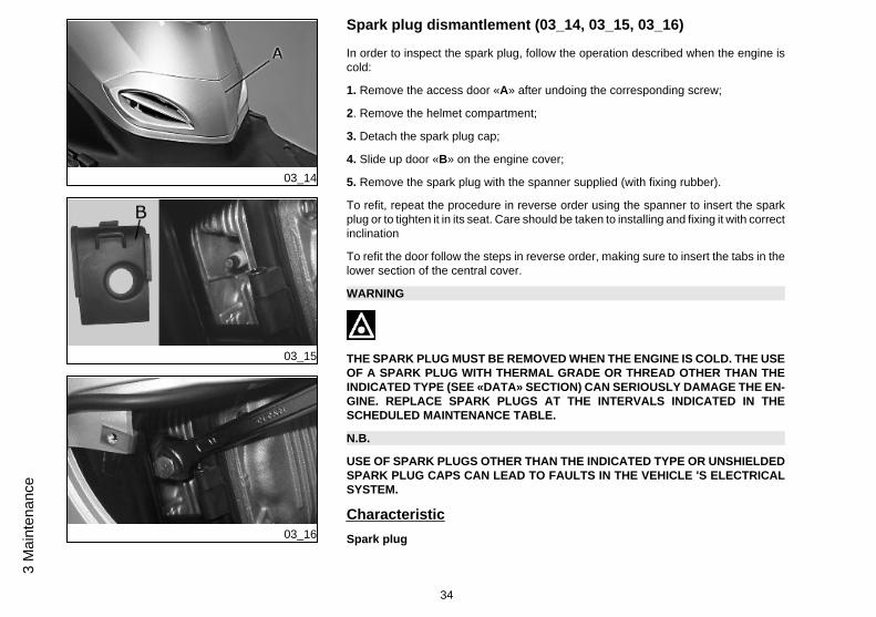
Spark plug dismantlement (03_14, 03_15, 03_16)
In order to inspect the spark plug, follow the operation described when the engine iscold:
1. Remove the access door «A» after undoing the corresponding screw;
2. Remove the helmet compartment;
3. Detach the spark plug cap;
4. Slide up door «B» on the engine cover;
5. Remove the spark plug with the spanner supplied (with fixing rubber).
To refit, repeat the procedure in reverse order using the spanner to insert the sparkplug or to tighten it in its seat. Care should be taken to installing and fixing it with correctinclination
To refit the door follow the steps in reverse order, making sure to insert the tabs in thelower section of the central cover.
WARNING
THE SPARK PLUG MUST BE REMOVED WHEN THE ENGINE IS COLD. THE USEOF A SPARK PLUG WITH THERMAL GRADE OR THREAD OTHER THAN THEINDICATED TYPE (SEE «DATA» SECTION) CAN SERIOUSLY DAMAGE THE EN-GINE. REPLACE SPARK PLUGS AT THE INTERVALS INDICATED IN THESCHEDULED MAINTENANCE TABLE.
N.B.
USE OF SPARK PLUGS OTHER THAN THE INDICATED TYPE OR UNSHIELDEDSPARK PLUG CAPS CAN LEAD TO FAULTS IN THE VEHICLE 'S ELECTRICALSYSTEM.
CharacteristicSpark plug
34
3 M
aint
enan
ce
CHAMPION RG6YC - NGK CR7EB
03_17
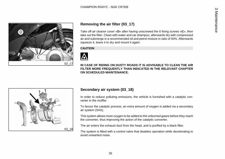
Removing the air filter (03_17)
Take off air cleaner cover «D» after having unscrewed the 6 fixing screws «C», thentake out the filter. Clean with water and car shampoo, afterwards dry with compressedair and submerge in a recommended oil and petrol mixture in ratio of 50%. Afterwardssqueeze it, leave it to dry and mount it again.
CAUTION
IN CASE OF RIDING ON DUSTY ROADS IT IS ADVISABLE TO CLEAN THE AIRFILTER MORE FREQUENTLY THAN INDICATED IN THE RELEVANT CHAPTERON SCHEDULED MAINTENANCE.
03_18
Secondary air system (03_18)
In order to reduce polluting emissions, the vehicle is furnished with a catalytic con-verter in the muffler.
To favour the catalytic process, an extra amount of oxygen is added via a secondaryair system (SAS).
This system allows more oxygen to be added to the unburned gases before they reachthe converter, thus improving the action of the catalytic converter.
The air enters the exhaust duct from the head, and is purified by a black filter.
The system is fitted with a control valve that disables operation while decelerating toavoid unwanted noise.
35
3 Maintenance

To ensure the best functioning of the SAS system, every 12,000 km the scooter shouldbe taken to an Authorised Piaggio Service Centre to have the filter cleaned (Sched-uled maintenance operations section).
The filter sponge should be cleaned with water and mild soap, then it should be driedwith a cloth and slight blows of compressed air.
CAUTION
CONTACT AN AUTHORISED PIAGGIO SERVICE CENTRE TO CARRY OUTTHESE OPERATIONS.
03_19
Checking the brake oil level (03_19)
The brake fluid reservoir is equipped with a sight glass «A» made of transparent ma-terial; the quantity of liquid contained in the sight glass indicates the level of liquid inthe reservoir.
When the sight glass «A» is full, the level inside the reservoir exceeds the MIN level;when it is partially full, the level drops to the MIN level; when it is fully empty, the levelof fluid in the reservoir is below the MIN level.
The brake fluid level may fall due to wear on the brake pads. In case the pad wear isbelow the minimum mark, contact an Authorised Service Centre to have the brakingsystem thoroughly checked. If you need to top up the level, follow the steps listedbelow. Unscrew the 2 screws «B», remove the reservoir cap «C » and pour in therequired quantity of fluid (the brake fluid level must be above minimum). Place thehandlebar in the riding position and pay attention not to tilt the vehicle in order to keepthe brake fluid reservoir in horizontal position when checking the fluid level.
36
3 M
aint
enan
ce

CAUTION
THE SYSTEM MUST ONLY BE TOPPED UP WITH DOT4 TYPE BRAKE FLUID.
WARNING
IN NORMAL CLIMATIC CONDITIONS IT IS ADVISABLE TO REPLACE THEABOVE-MENTIONED FLUID EVERY 2 YEAR. NEVER USE BRAKE FLUID CON-TAINED IN CONTAINERS WHICH ARE ALREADY OPEN OR PARTIALLY USED.
CAUTION
THE BRAKING CIRCUIT FLUID IS HIGHLY CORROSIVE. THEREFORE, WHENTOPPING UP, AVOID LETTING IT COME INTO CONTACT WITH THE PAINTEDPARTS OF THE VEHICLE. THE BRAKING CIRCUIT FLUID IS HYGROSCOPIC,THAT IS, IT ABSORBS HUMIDITY FROM THE SURROUNDING AIR. IF MOISTURECONTAINED IN THE BRAKE FLUID EXCEEDS A CERTAIN VALUE, THIS WILLRESULT IN INEFFICIENT BRAKING.
37
3 Maintenance
03_20
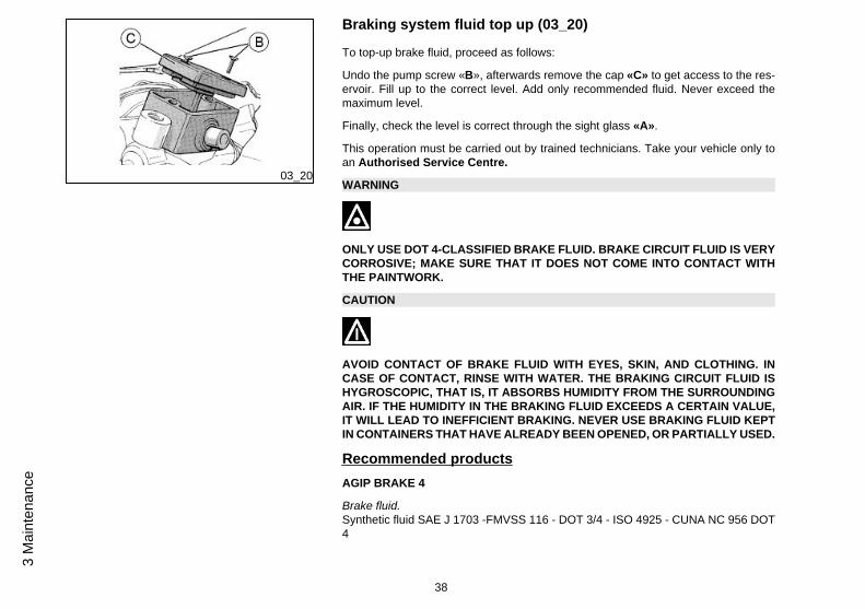
Braking system fluid top up (03_20)
To top-up brake fluid, proceed as follows:
Undo the pump screw «B», afterwards remove the cap «C» to get access to the res-ervoir. Fill up to the correct level. Add only recommended fluid. Never exceed themaximum level.
Finally, check the level is correct through the sight glass «A».
This operation must be carried out by trained technicians. Take your vehicle only toan Authorised Service Centre.
WARNING
ONLY USE DOT 4-CLASSIFIED BRAKE FLUID. BRAKE CIRCUIT FLUID IS VERYCORROSIVE; MAKE SURE THAT IT DOES NOT COME INTO CONTACT WITHTHE PAINTWORK.
CAUTION
AVOID CONTACT OF BRAKE FLUID WITH EYES, SKIN, AND CLOTHING. INCASE OF CONTACT, RINSE WITH WATER. THE BRAKING CIRCUIT FLUID ISHYGROSCOPIC, THAT IS, IT ABSORBS HUMIDITY FROM THE SURROUNDINGAIR. IF THE HUMIDITY IN THE BRAKING FLUID EXCEEDS A CERTAIN VALUE,IT WILL LEAD TO INEFFICIENT BRAKING. NEVER USE BRAKING FLUID KEPTIN CONTAINERS THAT HAVE ALREADY BEEN OPENED, OR PARTIALLY USED.
Recommended productsAGIP BRAKE 4
Brake fluid.Synthetic fluid SAE J 1703 -FMVSS 116 - DOT 3/4 - ISO 4925 - CUNA NC 956 DOT4
38
3 M
aint
enan
ce
03_21
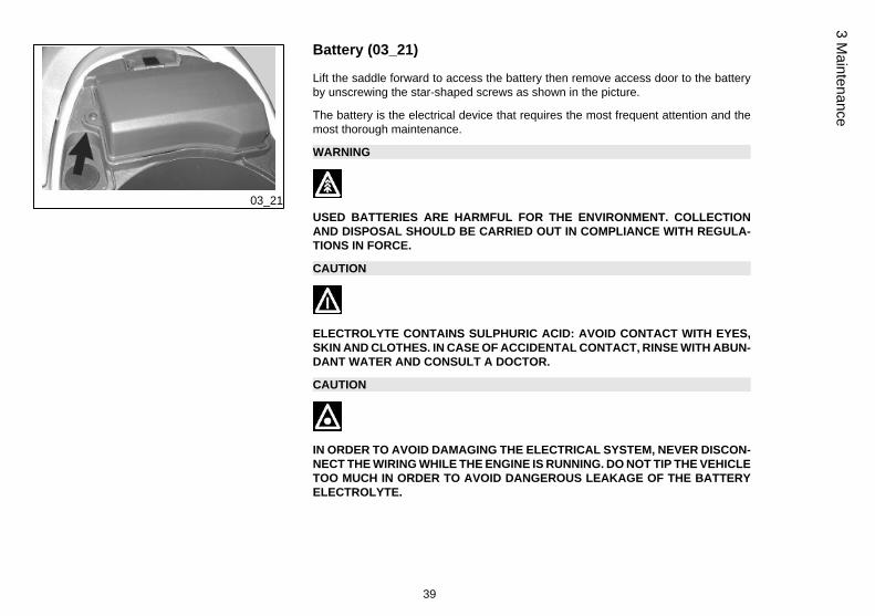
Battery (03_21)
Lift the saddle forward to access the battery then remove access door to the batteryby unscrewing the star-shaped screws as shown in the picture.
The battery is the electrical device that requires the most frequent attention and themost thorough maintenance.
WARNING
USED BATTERIES ARE HARMFUL FOR THE ENVIRONMENT. COLLECTIONAND DISPOSAL SHOULD BE CARRIED OUT IN COMPLIANCE WITH REGULA-TIONS IN FORCE.
CAUTION
ELECTROLYTE CONTAINS SULPHURIC ACID: AVOID CONTACT WITH EYES,SKIN AND CLOTHES. IN CASE OF ACCIDENTAL CONTACT, RINSE WITH ABUN-DANT WATER AND CONSULT A DOCTOR.
CAUTION
IN ORDER TO AVOID DAMAGING THE ELECTRICAL SYSTEM, NEVER DISCON-NECT THE WIRING WHILE THE ENGINE IS RUNNING. DO NOT TIP THE VEHICLETOO MUCH IN ORDER TO AVOID DANGEROUS LEAKAGE OF THE BATTERYELECTROLYTE.
39
3 Maintenance
Long periods of inactivity
Battery performance will be poor if the vehicle is not used for a long time. This is theresult of the natural phenomenon of battery discharging, and may be due to residualabsorption by vehicle components with constant power consumption. Poor batteryperformance may also be due to environmental conditions and the cleanliness of thepoles. In order to avoid difficult starts and/or irreversible damage to the battery, followany of these steps:
- At least once a month start the engine and run it slightly above idle speed for 10-15minutes. This keeps all the engine components, as well as the battery, in good workingorder.
- Take your vehicle to a garage (as indicated in the «Vehicle not used for extendedperiods» section) to have the battery removed. Have the battery cleaned, chargedfully and stored in a dry, ventilated place. Recharge at least once every twomonths.
N.B.
THE BATTERY MUST BE CHARGED WITH A CURRENT EQUAL TO 1/10 OF THERATED CAPACITY OF THE BATTERY AND FOR NOT LONGER THAN 10 HOURS.CONTACT AN AUTHORISED SERVICE CENTRE TO CARRY OUT THIS OPERA-TION SAFELY. WHEN REFITTING THE BATTERY MAKE SURE THE LEADS ARECORRECTLY CONNECTED TO THE TERMINALS.
WARNING
DO NOT DISCONNECT THE BATTERY CABLES WITH THE ENGINE RUNNING,THIS CAN CAUSE IRREPARABLE DAMAGE TO THE VEHICLE'S ELECTRONICCONTROL UNIT.
40
3 M
aint
enan
ce
WARNING
USED BATTERIES ARE HARMFUL FOR THE ENVIRONMENT. COLLECTIONAND DISPOSAL SHOULD BE CARRIED OUT IN COMPLIANCE WITH REGULA-TIONS IN FORCE.
03_22
03_23
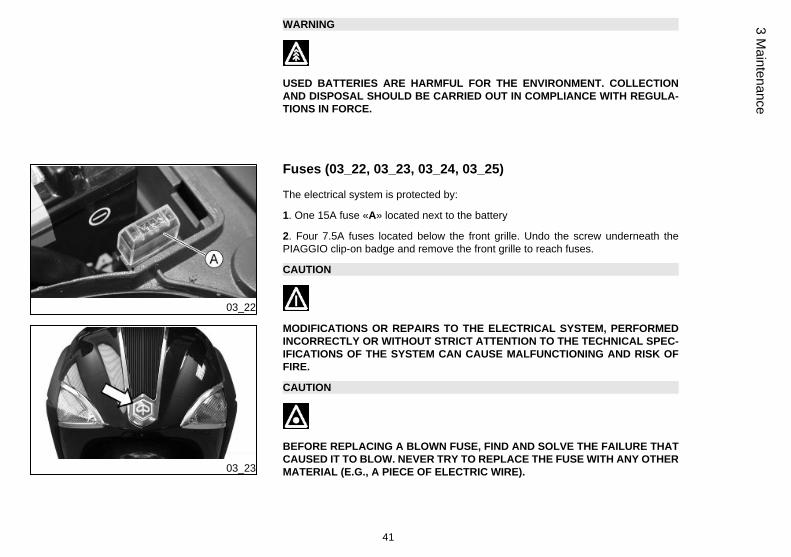
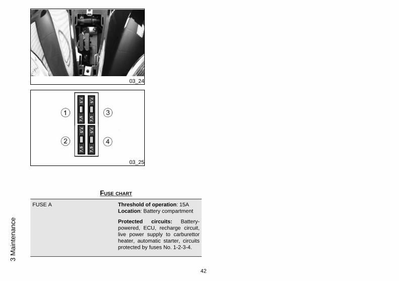
Fuses (03_22, 03_23, 03_24, 03_25)
The electrical system is protected by:
1. One 15A fuse «A» located next to the battery
2. Four 7.5A fuses located below the front grille. Undo the screw underneath thePIAGGIO clip-on badge and remove the front grille to reach fuses.
CAUTION
MODIFICATIONS OR REPAIRS TO THE ELECTRICAL SYSTEM, PERFORMEDINCORRECTLY OR WITHOUT STRICT ATTENTION TO THE TECHNICAL SPEC-IFICATIONS OF THE SYSTEM CAN CAUSE MALFUNCTIONING AND RISK OFFIRE.
CAUTION
BEFORE REPLACING A BLOWN FUSE, FIND AND SOLVE THE FAILURE THATCAUSED IT TO BLOW. NEVER TRY TO REPLACE THE FUSE WITH ANY OTHERMATERIAL (E.G., A PIECE OF ELECTRIC WIRE).
41
3 Maintenance
03_24
03_25
FUSE CHART
FUSE A Threshold of operation: 15ALocation: Battery compartment
Protected circuits: Battery-powered, ECU, recharge circuit,live power supply to carburettorheater, automatic starter, circuitsprotected by fuses No. 1-2-3-4.
42
3 M
aint
enan
ce

Fuse No. 1 Threshold of operation: 7.5
Location: front part
Protected circuits: Instrumentpanel bulbs, license plate lightbulb, rear tail light, front light bulb
Fuse No. 2 Threshold of operation: 7.5
Location: front part
Protected circuits: horn, oilpressure warning light, low fuelindicator and warning light, stoplight, starter button.
Fuse No. 3 Threshold of operation: 7.5
Location: front part
Protected circuits: Low-beamlight bulb
Fuse No. 4 Threshold of operation: 7.5
Location: front part
Protected circuits: high-beamlight bulb, high-beam warning light
BULBS
High/low beam light bulb Type: Halogen (H4)
43
3 Maintenance
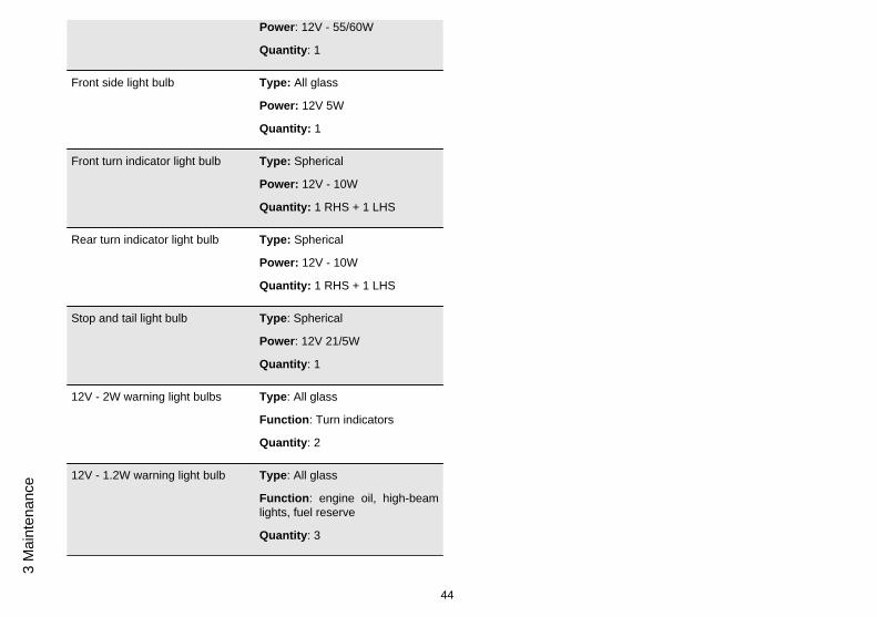
Power: 12V - 55/60W
Quantity: 1
Front side light bulb Type: All glass
Power: 12V 5W
Quantity: 1
Front turn indicator light bulb Type: Spherical
Power: 12V - 10W
Quantity: 1 RHS + 1 LHS
Rear turn indicator light bulb Type: Spherical
Power: 12V - 10W
Quantity: 1 RHS + 1 LHS
Stop and tail light bulb Type: Spherical
Power: 12V 21/5W
Quantity: 1
12V - 2W warning light bulbs Type: All glass
Function: Turn indicators
Quantity: 2
12V - 1.2W warning light bulb Type: All glass
Function: engine oil, high-beamlights, fuel reserve
Quantity: 3
44
3 M
aint
enan
ce

Instrument panel light bulbs Type: All glass
Power: 12V - 2W
Quantity: 4
License plate bulb Type: ALL GLASS
Power: 12V - 5W
Quantity: 1
03_26
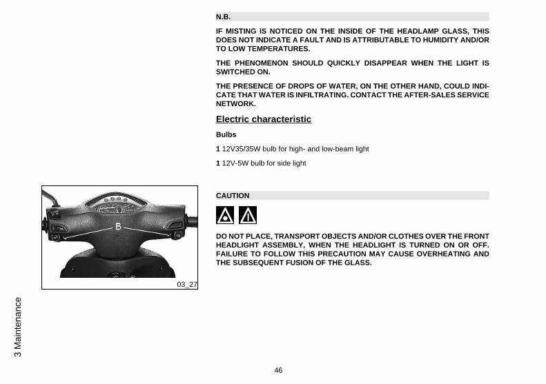
Front light group (03_27, 03_28)
To access the headlight bulbs, remove the front of the handlebar cover, as follows:
1) Remove the rear-view mirrors; for this operation follow the instructions describedand illustrated in the «Rear-view mirrors» section.
2) Unscrew the 3 screws holding the handlebar cover. The front central one «B» andthe rear 2 «C». Once this is done, the handlebar cover can be removed.
3) Remove the handlebar cover to access the headlight and the bulbs.
45
3 Maintenance
N.B.
IF MISTING IS NOTICED ON THE INSIDE OF THE HEADLAMP GLASS, THISDOES NOT INDICATE A FAULT AND IS ATTRIBUTABLE TO HUMIDITY AND/ORTO LOW TEMPERATURES.
THE PHENOMENON SHOULD QUICKLY DISAPPEAR WHEN THE LIGHT ISSWITCHED ON.
THE PRESENCE OF DROPS OF WATER, ON THE OTHER HAND, COULD INDI-CATE THAT WATER IS INFILTRATING. CONTACT THE AFTER-SALES SERVICENETWORK.
Electric characteristicBulbs
1 12V35/35W bulb for high- and low-beam light
1 12V-5W bulb for side light
03_27
CAUTION
DO NOT PLACE, TRANSPORT OBJECTS AND/OR CLOTHES OVER THE FRONTHEADLIGHT ASSEMBLY, WHEN THE HEADLIGHT IS TURNED ON OR OFF.FAILURE TO FOLLOW THIS PRECAUTION MAY CAUSE OVERHEATING ANDTHE SUBSEQUENT FUSION OF THE GLASS.
46
3 M
aint
enan
ce

03_28
03_29
03_30
Head light adjustment (03_29, 03_30)
Proceed as follows:
1. Place the vehicle in running order and with the tyres inflated to the prescribed pres-sure, on a flat surface 10 m away from a white screen situated in a shaded area,making sure that the longitudinal axis of the vehicle is perpendicular to the screen;
2. Turn on the headlight and check that the borderline of the projected light beam onthe screen is no higher than 9/10 or lower than 7/10 of the distance from the groundto the centre of the vehicle's headlamp;
3. If otherwise, adjust the right headlight with screw «A».
N.B.
THE ABOVE PROCEDURE COMPLIES WITH THE EUROPEAN STANDARDS RE-GARDING MAXIMUM AND MINIMUM HEIGHT OF LIGHT BEAMS. REFER TO THESTATUTORY REGULATIONS IN FORCE IN EVERY COUNTRY WHERE THE VE-HICLE IS USED.
47
3 Maintenance
03_31
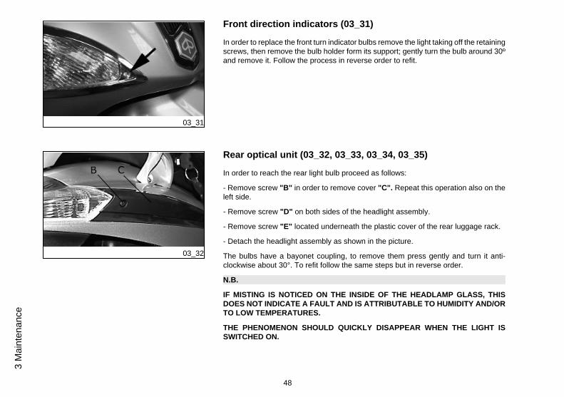
Front direction indicators (03_31)
In order to replace the front turn indicator bulbs remove the light taking off the retainingscrews, then remove the bulb holder form its support; gently turn the bulb around 30ºand remove it. Follow the process in reverse order to refit.
03_32
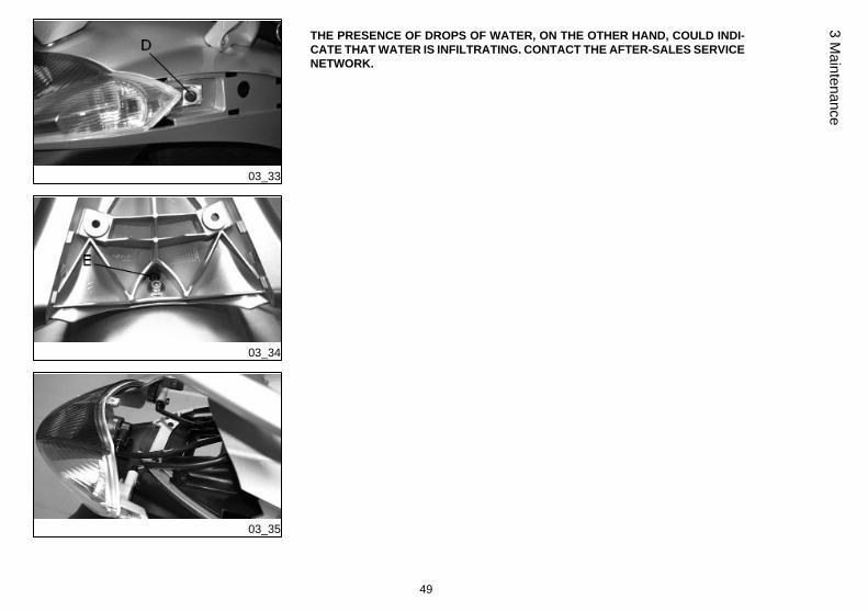
Rear optical unit (03_32, 03_33, 03_34, 03_35)
In order to reach the rear light bulb proceed as follows:
- Remove screw "B" in order to remove cover "C". Repeat this operation also on theleft side.
- Remove screw "D" on both sides of the headlight assembly.
- Remove screw "E" located underneath the plastic cover of the rear luggage rack.
- Detach the headlight assembly as shown in the picture.
The bulbs have a bayonet coupling, to remove them press gently and turn it anti-clockwise about 30°. To refit follow the same steps but in reverse order.
N.B.
IF MISTING IS NOTICED ON THE INSIDE OF THE HEADLAMP GLASS, THISDOES NOT INDICATE A FAULT AND IS ATTRIBUTABLE TO HUMIDITY AND/ORTO LOW TEMPERATURES.
THE PHENOMENON SHOULD QUICKLY DISAPPEAR WHEN THE LIGHT ISSWITCHED ON.
48
3 M
aint
enan
ce
03_33
03_34
03_35
THE PRESENCE OF DROPS OF WATER, ON THE OTHER HAND, COULD INDI-CATE THAT WATER IS INFILTRATING. CONTACT THE AFTER-SALES SERVICENETWORK.
49
3 Maintenance

03_36
Rear-view mirrors (03_36)
To adjust mirrors, loosen lock nut «A», place the mirror stem adequately and tightenthe lock nut. The rear-view mirror is assembled on a stem with a ball 'joint'. The mirrorcan be adjusted manually to the desired position.
03_37
03_38
Idle adjustment (03_37, 03_38)
To adjust idle speed it is necessary to operate the idle set screw «A » located in thecarburettor. To do this,lift the saddle, remove the rubber cover «B» and use a Phillips screwdriver.
Adjust the idle speed with the rear wheel off the ground (vehicle on stand) and with awarm engine: undo or tighten the screw until the engine idles smoothly, i.e. withoutthe rear wheel being moved by the engine. If adjustment in these conditions is difficult,contact an Authorised Service Centre.
CAUTION
WHEN ADJUSTING IDLE SPEED, BE CAREFUL NOT TO TOUCH HOT PARTS OFTHE ENGINE TO AVOID BURNS.
CharacteristicEngine idle speed
1,650±100 rpm
50
3 M
aint
enan
ce
03_39
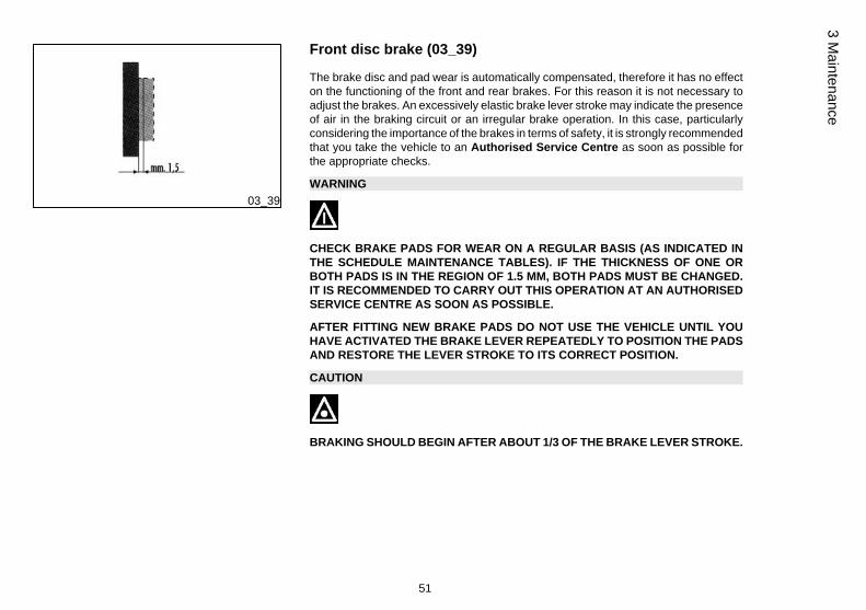
Front disc brake (03_39)
The brake disc and pad wear is automatically compensated, therefore it has no effecton the functioning of the front and rear brakes. For this reason it is not necessary toadjust the brakes. An excessively elastic brake lever stroke may indicate the presenceof air in the braking circuit or an irregular brake operation. In this case, particularlyconsidering the importance of the brakes in terms of safety, it is strongly recommendedthat you take the vehicle to an Authorised Service Centre as soon as possible forthe appropriate checks.
WARNING
CHECK BRAKE PADS FOR WEAR ON A REGULAR BASIS (AS INDICATED INTHE SCHEDULE MAINTENANCE TABLES). IF THE THICKNESS OF ONE ORBOTH PADS IS IN THE REGION OF 1.5 MM, BOTH PADS MUST BE CHANGED.IT IS RECOMMENDED TO CARRY OUT THIS OPERATION AT AN AUTHORISEDSERVICE CENTRE AS SOON AS POSSIBLE.
AFTER FITTING NEW BRAKE PADS DO NOT USE THE VEHICLE UNTIL YOUHAVE ACTIVATED THE BRAKE LEVER REPEATEDLY TO POSITION THE PADSAND RESTORE THE LEVER STROKE TO ITS CORRECT POSITION.
CAUTION
BRAKING SHOULD BEGIN AFTER ABOUT 1/3 OF THE BRAKE LEVER STROKE.
51
3 Maintenance

03_40
Rear drum brake (03_40)
Operate adjusting nut «B» and loosen lock nut «A» shown in the figure. Note thatwhen the throttle is in idle the wheel should rotate free. After the adjustment, screwlock nut «A».
CAUTION
BRAKING SHOULD BEGIN AFTER ABOUT 1/3 OF THE BRAKE LEVER STROKE.
03_41
Puncture (03_41)
The vehicle is equipped with Tubeless tyres. When there is a puncture, Tubeless tyres- unlike tyres with inner tubes - go flat very slowly. This offers greater riding safety. Atyre that goes flat very slowly can be repaired with an "Inflate and Repair" spray. Tyresshould be later fully repaired or replaced at an Authorised Service Centre.
Inactivity of the vehicle
We recommend carrying out the following operations:1. General cleaning of the vehicle.
2 - With the engine off and the piston at bottom dead centre position, remove the sparkplug and pour 1÷2 cc of motor oil through its hole. Operate the starter motor 3-4 timesletting the engine perform a few revolutions, then remount the spark plug.
52
3 M
aint
enan
ce

3 - Drain up all the vehicle's fuel; spread antirust grease on the uncoated metal parts;keep the wheels lifted above the ground.
4 - For the battery, follow the procedures described in the «Battery» section.
5 - Drain the petrol from the carburettor tank.
6 - Replace engine oil.
Recommended productseni i-Ride PG 5W-40
Synthetic based lubricant for high-performance four-stroke engines.JASO MA, MA2 - API SL - ACEA A3
Cleaning the vehicle
Use a low pressure jet of water to soften the caked dirt and mud deposited on thepainted surfaces. Once softened, sponge off mud and dirt using a car body spongesoaked in a car body shampoo and water solution (2-4% of car shampoo in water).Then rinse with abundant water, and dry with a shammy cloth. For the engine exterior,use petrol, a brush and clean cloths. Petrol can damage paintwork. Remember thatany polishing with silicone wax must always be preceded by washing.
WARNING
To avoid the appearance of oxidations, wash the vehicle every time it is used incertain areas or in special conditions of:
· Environmental / seasonal conditions: use of salt, de-icer chemical products onthe road in winter.
· Air pollution: city and/or industrial areas.
· Salinity and humidity of the atmosphere: marine areas, hot and wet weather.
53
3 Maintenance

WARNING
. Prevent deposits from remaining on the bodywork, industrial and pollutantresidual dust, tar spots, dead insects, bird droppings, etc.
· Do not park the vehicle under the trees. In some seasons, in fact, residues,resins, fruits or leaves may fall from the trees, containing chemicals that areharmful to the paintwork.
CAUTION
DETERGENTS POLLUTE WATER. THEREFORE THE VEHICLE SHOULD BEWASHED IN AN AREA EQUIPPED FOR THE COLLECTION AND PURIFICATIONOF THE LIQUIDS USED.
WARNING
NEVER WASH THE VEHICLE UNDER DIRECT SUNLIGHT, ESPECIALLY IN SUM-MER WHEN THE BODYWORK IS STILL HOT, AS THE CAR SHAMPOO MAY DRYBEFORE BEING RINSED OFF, AND COULD DAMAGE THE PAINTWORK. NEVERUSE RAGS SOAKED IN PETROL OR DIESEL OIL TO CLEAN THE PAINTED ORPLASTIC SURFACES, IN ORDER TO PREVENT THEM LOSING THEIR SHINEAND MECHANICAL CHARACTERISTICS.
WARNING
WHEN WASHING THE ENGINE WITH A HIGH-PRESSURE WATER JET:
• ONLY USE FAN SPRAY JETS.
54
3 M
aint
enan
ce
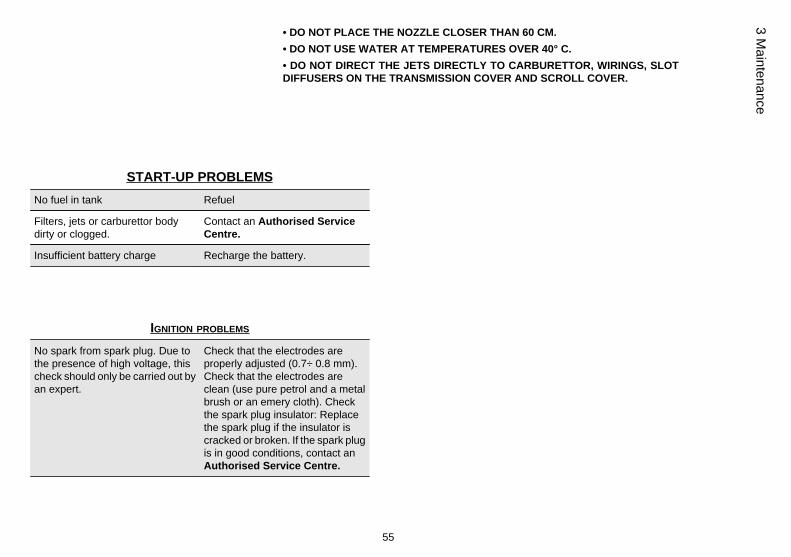
• DO NOT PLACE THE NOZZLE CLOSER THAN 60 CM.• DO NOT USE WATER AT TEMPERATURES OVER 40° C.• DO NOT DIRECT THE JETS DIRECTLY TO CARBURETTOR, WIRINGS, SLOTDIFFUSERS ON THE TRANSMISSION COVER AND SCROLL COVER.
START-UP PROBLEMSNo fuel in tank Refuel
Filters, jets or carburettor bodydirty or clogged.
Contact an Authorised ServiceCentre.
Insufficient battery charge Recharge the battery.
IGNITION PROBLEMS
No spark from spark plug. Due tothe presence of high voltage, thischeck should only be carried out byan expert.
Check that the electrodes areproperly adjusted (0.7÷ 0.8 mm).Check that the electrodes areclean (use pure petrol and a metalbrush or an emery cloth). Checkthe spark plug insulator: Replacethe spark plug if the insulator iscracked or broken. If the spark plugis in good conditions, contact anAuthorised Service Centre.
55
3 Maintenance

LACK OF COMPRESSION
Spark plug adapter "worn", valveclearance not adequate; wornpiston gas rings
Contact an Authorised ServiceCentre.
HIGH CONSUMPTION AND LOW PERFORMANCEAir filter blocked or dirty. Clean with water and shampoo and
impregnate with petrol and specificoil («Air filter removal» section)
INEFFICIENT BRAKINGOil on drum or disc. Worn Pads/Shoes
Contact an Authorised ServiceCentre
incorrect rear brake adjustment Adjust
INEFFICIENT SUSPENSIONInefficient shock absorbers, oilleakage, deteriorated end of strokebuffers.
Contact an Authorised ServiceCentre
56
3 M
aint
enan
ce

AUTOMATIC TRANSMISSION PROBLEMSDeteriorated CVT rollers and/ordrive belt and/or clutch
Contact an Authorised ServiceCentre
EXHAUST NOISEDepression tube damaged/disconnected or secondary valvedamaged
Contact an Authorised ServiceCentre
STAND DOES NOT RETURN TO POSITIONPresence of dirt Clean and grease
57
3 Maintenance

58
3 M
aint
enan
ce

Liberty 125-150
Chap. 04Technical data
59
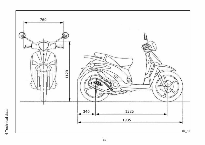
04_01
60
4 Te
chni
cal d
ata
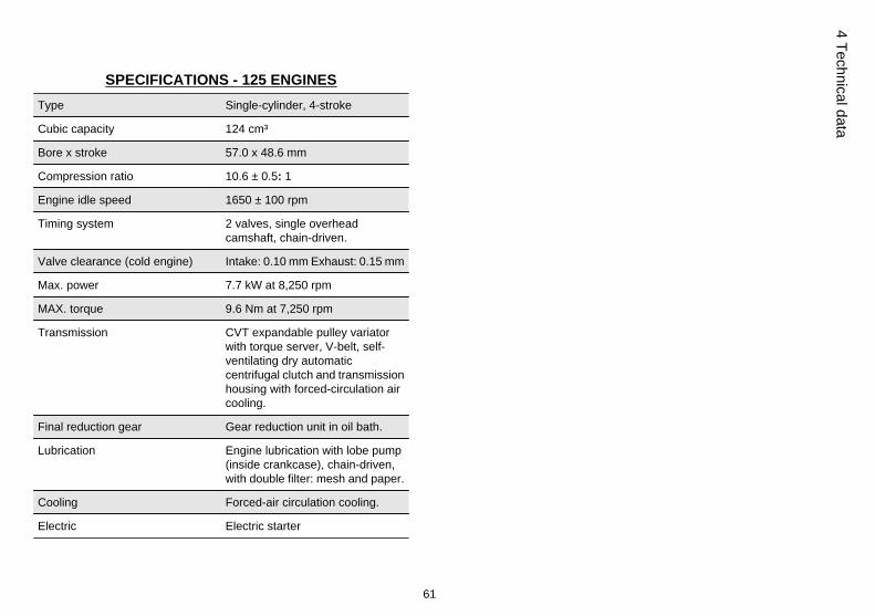
SPECIFICATIONS - 125 ENGINESType Single-cylinder, 4-stroke
Cubic capacity 124 cm³
Bore x stroke 57.0 x 48.6 mm
Compression ratio 10.6 ± 0.5: 1
Engine idle speed 1650 ± 100 rpm
Timing system 2 valves, single overheadcamshaft, chain-driven.
Valve clearance (cold engine) Intake: 0.10 mm Exhaust: 0.15 mm
Max. power 7.7 kW at 8,250 rpm
MAX. torque 9.6 Nm at 7,250 rpm
Transmission CVT expandable pulley variatorwith torque server, V-belt, self-ventilating dry automaticcentrifugal clutch and transmissionhousing with forced-circulation aircooling.
Final reduction gear Gear reduction unit in oil bath.
Lubrication Engine lubrication with lobe pump(inside crankcase), chain-driven,with double filter: mesh and paper.
Cooling Forced-air circulation cooling.
Electric Electric starter
61
4 Technical data
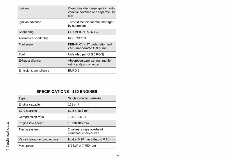
Ignition Capacitive discharge ignition, withvariable advance and separate HVcoil.
Ignition advance Three-dimensional map managedby control unit
Spark plug CHAMPION RG 6 YC
Alternative spark plug NGK CR7EB
Fuel system KEIHIN CVK 27 carburettor andvacuum-operated fuel pump.
Fuel Unleaded petrol (95 RON)
Exhaust silencer Absorption-type exhaust mufflerwith catalytic converter.
Emissions compliance EURO 3
SPECIFICATIONS - 150 ENGINESType Single-cylinder, 4-stroke
Engine capacity 151 cm³
Bore x stroke 62.8 x 48.6 mm
Compression ratio 10.6 ± 0.5 : 1
Engine idle speed 1,650±100 rpm
Timing system 2 valves, single overheadcamshaft, chain-driven.
Valve clearance (cold engine) Intake: 0.10 mm Exhaust: 0.15 mm
Max. power 8.9 kW at 7,750 rpm
62
4 Te
chni
cal d
ata

MAX. torque 11.8 Nm at 6,500 rpm
Transmission CVT expandable pulley variatorwith torque server, V-belt, self-ventilating dry automaticcentrifugal clutch and transmissionhousing with forced-circulation aircooling.
Final reduction gear Gear reduction unit in oil bath.
Lubrication Engine lubrication with lobe pump(inside crankcase), chain-driven,with double filter: mesh and paper.
Cooling Forced-air circulation cooling.
Electric Electric starter
Ignition Capacitive discharge ignition, withvariable advance and separate HVcoil.
Ignition advance Three-dimensional map managedby control unit
Spark plug CHAMPION RG 6 YC
Alternative spark plug NGK CR7EB
Fuel system KEIHIN CVK 27 carburettor andvacuum-operated fuel pump.
Fuel Unleaded petrol (95 RON)
Exhaust silencer Absorption-type exhaust mufflerwith catalytic converter.
Emissions compliance EURO 3
63
4 Technical data
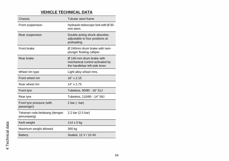
VEHICLE TECHNICAL DATAChassis Tubular steel frame
Front suspension Hydraulic telescopic fork with Ø 30-mm stem.
Rear suspension Double-acting shock absorber,adjustable to four positions atpreloading.
Front brake Ø 240mm drum brake with twin-plunger floating calliper.
Rear brake Ø 140-mm drum brake withmechanical control activated bythe handlebar left-side lever.
Wheel rim type Light alloy wheel rims.
Front wheel rim 16'' x 2.15
Rear wheel rim 14'' x 2.75
Front tyre Tubeless, 90/80 - 16" 51J
Rear tyre Tubeless, 110/80 - 14" 59J
Front tyre pressure (withpassenger)
2 bar (- bar)
Tekanan roda belakang (denganpenumpang)
2.2 bar (2.5 bar)
Kerb weight 114 ± 5 kg
Maximum weight allowed 300 kg
Battery Sealed, 12 V / 10 Ah
64
4 Te
chni
cal d
ata
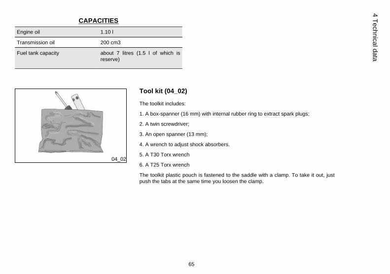
CAPACITIESEngine oil 1.10 l
Transmission oil 200 cm3
Fuel tank capacity about 7 litres (1.5 l of which isreserve)
04_02
Tool kit (04_02)
The toolkit includes:
1. A box-spanner (16 mm) with internal rubber ring to extract spark plugs;
2. A twin screwdriver;
3. An open spanner (13 mm);
4. A wrench to adjust shock absorbers.
5. A T30 Torx wrench
6. A T25 Torx wrench
The toolkit plastic pouch is fastened to the saddle with a clamp. To take it out, justpush the tabs at the same time you loosen the clamp.
65
4 Technical data

66
4 Te
chni
cal d
ata

Liberty 125-150
Chap. 05Spare parts and
accessories
67
05_01
05_02
Warnings (05_01, 05_02)
WARNING
IT IS RECOMMENDED THAT "ORIGINAL PIAGGIO SPARE PARTS" BE USED,AS THESE ARE THE ONLY ONES OFFERING YOU THE SAME QUALITY AS-SURANCE AS THOSE INITIALLY FITTED ON THE VEHICLE.
IT SHOULD BE REMEMBERED THAT USING NON-ORIGINAL SPARE PARTSCAUSES YOUR WARRANTY RIGHTS TO EXPIRE.
WARNING
PIAGGIO MARKETS ITS OWN LINE OF ACCESSORIES THAT ARE RECOG-NISED AND GUARANTEED FOR USE. IT IS THEREFORE ESSENTIAL TO CON-TACT AN AUTHORISED DEALER OR SERVICE CENTRE IN ORDER TO CHOOSEAND FIT ACCESSORIES CORRECTLY. THE USE OF NON-ORIGINAL ACCES-SORIES MAY AFFECT THE STABILITY AND OPERATION OF YOUR VEHICLEAND REDUCE SAFETY LEVELS WITH POTENTIAL RISKS FOR THE RIDER.
68
5 Sp
are
parts
and
acc
esso
ries
Liberty 125-150
Chap. 06Scheduled
maintenance
69
06_01
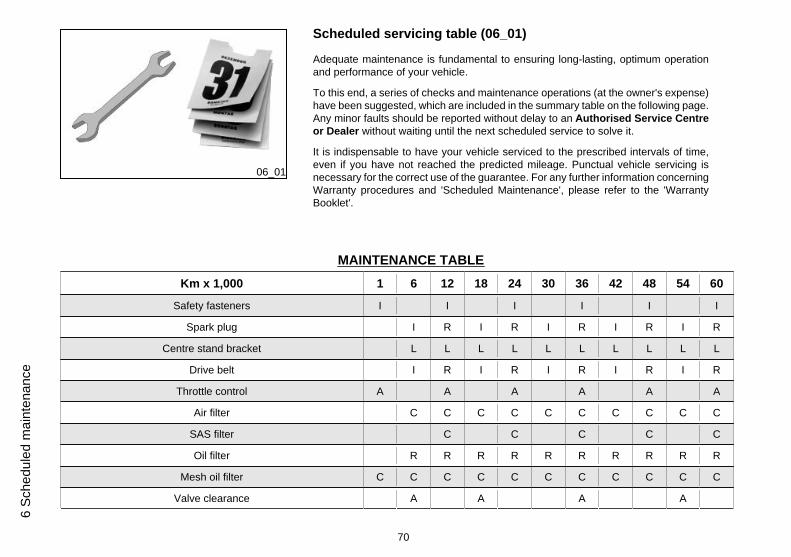
Scheduled servicing table (06_01)
Adequate maintenance is fundamental to ensuring long-lasting, optimum operationand performance of your vehicle.
To this end, a series of checks and maintenance operations (at the owner's expense)have been suggested, which are included in the summary table on the following page.Any minor faults should be reported without delay to an Authorised Service Centreor Dealer without waiting until the next scheduled service to solve it.
It is indispensable to have your vehicle serviced to the prescribed intervals of time,even if you have not reached the predicted mileage. Punctual vehicle servicing isnecessary for the correct use of the guarantee. For any further information concerningWarranty procedures and 'Scheduled Maintenance', please refer to the 'WarrantyBooklet'.
MAINTENANCE TABLEKm x 1,000 1 6 12 18 24 30 36 42 48 54 60
Safety fasteners I I I I I I
Spark plug I R I R I R I R I R
Centre stand bracket L L L L L L L L L L
Drive belt I R I R I R I R I R
Throttle control A A A A A A
Air filter C C C C C C C C C C
SAS filter C C C C C
Oil filter R R R R R R R R R R
Mesh oil filter C C C C C C C C C C C
Valve clearance A A A A
70
6 Sc
hedu
led
mai
nten
ance
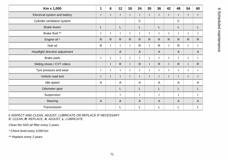
Km x 1,000 1 6 12 18 24 30 36 42 48 54 60
Electrical system and battery I I I I I I I I I I I
Cylinder ventilation system C C
Brake levers L L L L L L
Brake fluid ** I I I I I I I I I I I
Engine oil * R R R R R R R R R R R
Hub oil R I I I R I R I R I I
Headlight direction adjustment A A A A A
Brake pads I I I I I I I I I I I
Sliding shoes / CVT rollers I R I R I R I R I R
Tyre pressure and wear I I I I I I I I I I I
Vehicle road test I I I I I I I I I I I
Idle speed A A A A A A
Odometer gear L L L L L
Suspension I I I I I
Steering A A A A A A
Transmission L L L L L
I: INSPECT AND CLEAN, ADJUST, LUBRICATE OR REPLACE IF NECESSARYC: CLEAN, R: REPLACE, A: ADJUST, L: LUBRICATE
Clean the SAS air filter every 2 years
* Check level every 3,000 km
** Replace every 2 years
71
6 Scheduled maintenance
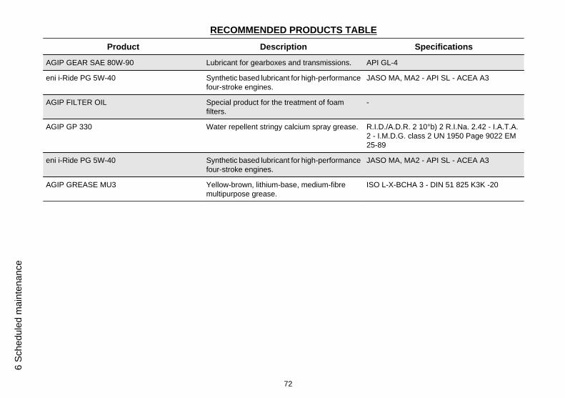
RECOMMENDED PRODUCTS TABLEProduct Description Specifications
AGIP GEAR SAE 80W-90 Lubricant for gearboxes and transmissions. API GL-4
eni i-Ride PG 5W-40 Synthetic based lubricant for high-performancefour-stroke engines.
JASO MA, MA2 - API SL - ACEA A3
AGIP FILTER OIL Special product for the treatment of foamfilters.
-
AGIP GP 330 Water repellent stringy calcium spray grease. R.I.D./A.D.R. 2 10°b) 2 R.I.Na. 2.42 - I.A.T.A.2 - I.M.D.G. class 2 UN 1950 Page 9022 EM25-89
eni i-Ride PG 5W-40 Synthetic based lubricant for high-performancefour-stroke engines.
JASO MA, MA2 - API SL - ACEA A3
AGIP GREASE MU3 Yellow-brown, lithium-base, medium-fibremultipurpose grease.
ISO L-X-BCHA 3 - DIN 51 825 K3K -20
72
6 Sc
hedu
led
mai
nten
ance
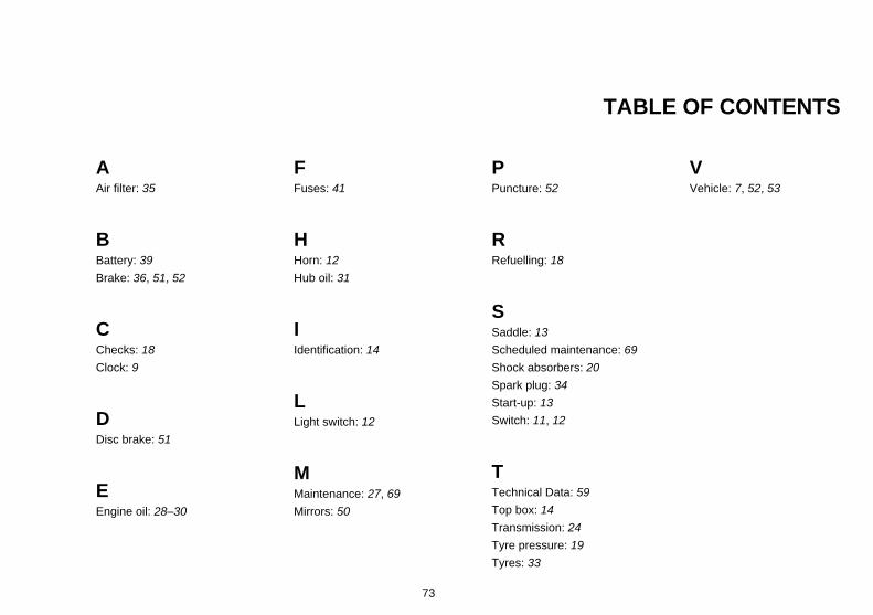
TABLE OF CONTENTS
AAir filter: 35
BBattery: 39Brake: 36, 51, 52
CChecks: 18Clock: 9
DDisc brake: 51
EEngine oil: 28–30
FFuses: 41
HHorn: 12Hub oil: 31
IIdentification: 14
LLight switch: 12
MMaintenance: 27, 69Mirrors: 50
PPuncture: 52
RRefuelling: 18
SSaddle: 13Scheduled maintenance: 69Shock absorbers: 20Spark plug: 34Start-up: 13Switch: 11, 12
TTechnical Data: 59Top box: 14Transmission: 24Tyre pressure: 19Tyres: 33
VVehicle: 7, 52, 53
73

The descriptions and images in this publication are given for illustrative purposes only and are not binding. While the basic characteristics as described and illustrated in this booklet remain unchanged,Piaggio & C. S.p.A. reserves the right, at any time and without being required to update this publication beforehand, to make any changes to components, parts or accessories, which it considers
necessary to improve the product or which are required for manufacturing or construction reasons.
Not all versions/models shown in this publication are available in all countries. The availability of each model should be checked at the official PIAGGIO sales network.
© Copyright 2013 - Piaggio & C. S.p.A. All rights reserved. Reproduction of this publication in whole or in part is prohibited.
Piaggio & C. S.p.A. Viale Rinaldo Piaggio, 25 - 56025 PONTEDERA (PI), Italy
www.piaggio.com