Embed Size (px)
DESCRIPTION
PIC18C CAN Routines in ‘C’ AN738
Citation preview

M AN738PIC18C CAN Routines in ‘C’
INTRODUCTION
The Microchip PIC18C family of microcontrollers pro-vides an integrated Controller Area Network (CAN)solution, along with other PICmicro® features. Althoughoriginally intended for the automotive industry, CAN isfinding its way into other control applications. Becauseof the wide applicability of the CAN protocol, thereexists a need to develop a software library that hidesthe intricate details of CAN registers and allows devel-opers to focus on application logic. This applicationnote provides such functions.
For details about the PIC18C family of microcontrollers,refer to the PIC18CXX8 Data Sheet (DS30475) and thePICmicro® 18C MCU Family Reference Manual(DS39500).
OVERVIEW OF THE PIC18C CAN MODULE
The PIC18C family of microcontrollers contains a CANmodule that provides the same register and functionalinterface for all PIC18C microcontrollers.
The module features are:
• Implementation of the CAN protocols CAN 1.2, CAN 2.0A, and CAN 2.0B
• Standard and extended data frames• Data length of 0 - 8 bytes• Programmable bit rate up to 1 Mbit/s
• Support for remote frame• Double buffered receiver with two prioritized
received message storage buffers• Six full (Standard/Extended Identifier) acceptance
filters, two associated with the high priority receive buffer and four associated with the low priority receive buffer
• Two full acceptance filter masks, one each associ-ated with the high and low priority receive buffers
• Three transmit buffers with application specified prioritization and abort capability
• Programmable wake-up functionality with integrated low-pass filter
• Programmable Loopback mode and program-mable state clocking supports self-test operation
• Signaling via interrupt capabilities for all CAN receiver and transmitter error states
• Programmable clock source
• Programmable link to timer module for time-stamping and network synchronization
• Low power SLEEP mode
Figure 1 shows a block diagram of the CAN modulebuffers and protocol engine.
Author: Nilesh Rajbharti Microchip Technology, Inc.
2001 Microchip Technology Inc. DS00738B-page 1

AN738
FIGURE 1: CAN BUFFERS AND PROTOCOL ENGINE BLOCK DIAGRAM
Acceptance FilterRXF2
RXB1
Accept
Accept
Identifier
Data Field Data Field
Identifier
Acceptance MaskRXM1
Acceptance FilterRXF3
Acceptance FilterRXF4
Acceptance FilterRXF5
MAB
Acceptance MaskRXM0
Acceptance FilterRXF0
Acceptance FilterRXF1
RXB0
MS
GR
EQ
TXB2
TX
AB
TT
XLA
RB
TX
ER
RM
TX
BU
FF
ME
SS
AG
E
MessageQueueControl
Transmit Byte Sequencer
MS
GR
EQ
TXB1
TX
AB
TT
XLA
RB
TX
ER
RM
TX
BU
FF
ME
SS
AG
E
MS
GR
EQ
TXB0
TX
AB
TT
XLA
RB
TX
ER
RM
TX
BU
FF
ME
SS
AG
E
Receive ShiftTransmit Shift
ReceiveError
TransmitError
Protocol
RXERRCNT
TXERRCNT
ErrPasBusOff
FiniteState
Machine
Counter
Counter
TransmitLogic
BitTimingLogic
TX RX
Bit TimingGenerator
PROTOCOLENGINE
BUFFERS
CRC CheckCRC Generator
DS00738B-page 2 2001 Microchip Technology Inc.
AN738
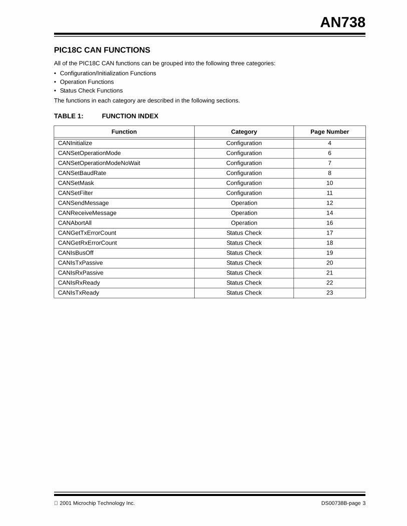
PIC18C CAN FUNCTIONS
All of the PIC18C CAN functions can be grouped into the following three categories:
• Configuration/Initialization Functions• Operation Functions
• Status Check Functions
The functions in each category are described in the following sections.
TABLE 1: FUNCTION INDEX
Function Category Page Number
CANInitialize Configuration 4
CANSetOperationMode Configuration 6
CANSetOperationModeNoWait Configuration 7
CANSetBaudRate Configuration 8
CANSetMask Configuration 10
CANSetFilter Configuration 11
CANSendMessage Operation 12
CANReceiveMessage Operation 14
CANAbortAll Operation 16
CANGetTxErrorCount Status Check 17
CANGetRxErrorCount Status Check 18
CANIsBusOff Status Check 19
CANIsTxPassive Status Check 20
CANIsRxPassive Status Check 21
CANIsRxReady Status Check 22
CANIsTxReady Status Check 23
2001 Microchip Technology Inc. DS00738B-page 3

AN738
CONFIGURATION/INITIALIZATION FUNCTIONS:
CANInitialize
This function initializes the PIC18C CAN module with given parameters.
Syntax
Parameters
SJW
[in] SJW value as defined in PIC18CXX8 data sheet (must be between 1 through 4).
BRP
[in] BRP value as defined in PIC18CXX8 data sheet (must be between 1 through 64).
PHSEG1
[in] PHSEG1 value as defined in PIC18CXX8 data sheet (must be between 1 through 8).
PHSEG2
[in] PHSEG2 value as defined in PIC18CXX8 data sheet (must be between 1 through 8).
PROPSEG
[in] PROPSEG value as defined in PIC18CXX8 data sheet (must be between 1 through 8).
config
[in] Specifies an enumerated value of the type CAN_CONFIG_FLAGS. This parameter can be any combination(AND’d together) of the following values:
Return ValuesNone.
Pre-conditionNone.
Side EffectsAll pending CAN messages are aborted.
Value Meaning
CAN_CONFIG_DEFAULT Specifies default flags
CAN_CONFIG_PHSEG2_PRG_ON Specifies to use supplied PHSEG2 value
CAN_CONFIG_PHSEG2_PRG_OFF Specifies to use maximum of PHSEG1 or Information Processing Time (IPT), whichever is greater
CAN_CONFIG_LINE_FILTER_ON Specifies to use CAN bus line filter for wake-up
CAN_CONFIG_LINE_FILTER_OFF Specifies to not use CAN bus line filter for wake-up
CAN_CONFIG_SAMPLE_ONCE Specifies to sample bus once at the sample point
CAN_CONFIG_SAMPLE_THRICE Specifies to sample bus three times prior to the sample point
CAN_CONFIG_ALL_MSG Specifies to accept all messages including invalid ones
CAN_CONFIG_VALID_XTD_MSG Specifies to accept only valid Extended Identifier messages
CAN_CONFIG_VALID_STD_MSG Specifies to accept only valid Standard Identifier messages
CAN_CONFIG_ALL_VALID_MSG Specifies to accept all valid messages
CAN_CONFIG_DBL_BUFFER_ON Specifies to hardware double buffer Receive Buffer 1
CAN_CONFIG_DBL_BUFFER_OFF Specifies to not hardware double buffer Receive Buffer 1
void CANInitialize( BYTE SJW,BYTE BRP,BYTE PHSEG1,BYTE PHSEG2,BYTE PROPSEG,enum CAN_CONFIG_FLAGS config);
DS00738B-page 4 2001 Microchip Technology Inc.

AN738
Remarks This function does not allow the calling function to specify receive buffer mask and filter values. All mask registers areset to 0x00, which essentially disables the message filter mechanism. If the application requires message filter opera-tion, it must perform initialization in discrete steps as shown in Example 1.
EXAMPLE 1: INITIALIZE CAN MODULE
// Initialize CAN module with no message filteringCANInitialize(SJW, BRP, PHSEG1, PHSEG2, PROPSEG, config)
// Set CAN module into configuration modeCANSetOperationMode(CAN_OP_MODE_CONFIG);
// Set Buffer 1 Mask valueCANSetMask(CAN_MASK_B1, MaskForBuffer1);
// Set Buffer 2 Mask valueCANSetMask(CAN_MASK_B2, MaskForBuffer2);
// Set Buffer 1 Filter valuesCANSetFilter(CAN_FILTER_B1_F1, Filter1ForBuffer1, Buffer1MessageType);CANSetFilter(CAN_FILTER_B1_F2, Filter2ForBuffer1, Buffer1MessageType);CANSetFilter(CAN_FILTER_B2_F1, Filter1ForBuffer2, Buffer2MessageType);CANSetFilter(CAN_FILTER_B2_F2, Filter2ForBuffer2, Buffer2MessageType);CANSetFilter(CAN_FILTER_B2_F3, Filter3ForBuffer2, Buffer2MessageType);CANSetFilter(CAN_FILTER_B2_F4, Filter4ForBuffer2, Buffer2MessageType);
// Set CAN module into Normal modeCANSetOperationMode(CAN_OP_MODE_NORMAL);
EXAMPLE 2: USAGE OF CANInitialize
// Initialize at 125kbps at 20 MHz, all valid Extended messagesCANInitialize(1, 5, 7, 6, 2, CAN_CONFIG_VALID_XTD_MSG);
2001 Microchip Technology Inc. DS00738B-page 5

AN738
CANSetOperationMode
This function changes the PIC18C CAN module operation mode.
Syntax
Parameters
mode
[in] Specifies an enumerated value of the type CAN_OP_MODE. The only permitted values are:
Return Values
None.
Pre-condition
None.
Side Effects
If CAN_OP_MODE_CONFIG is requested, all pending messages will be aborted.
Remarks
This is a blocking function. It waits for a given mode to be accepted by the CAN module and then returns the control. Ifa non-blocking call is required, see the CANSetOperationModeNoWait function.
EXAMPLE 3: USAGE OF CANSetOperationMode
CANSetOperationMode(CAN_OP_MODE_CONFIG);// Module IS in CAN_OP_MODE_CONFIG mode.
Value Meaning
CAN_OP_MODE_NORMAL Specifies Normal mode of operation
CAN_OP_MODE_SLEEP Specifies SLEEP mode of operation
CAN_OP_MODE_LOOP Specifies Loopback mode of operation
CAN_OP_MODE_LISTEN Specifies Listen Only mode of operation
CAN_OP_MODE_CONFIG Specifies Configuration mode of operation
void CANSetOperationMode(enum CAN_OP_MODE mode);
DS00738B-page 6 2001 Microchip Technology Inc.
AN738
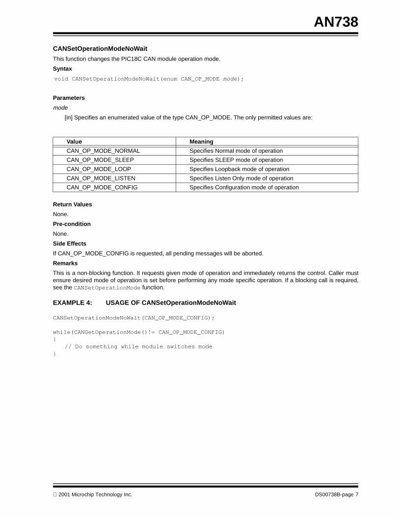
CANSetOperationModeNoWait
This function changes the PIC18C CAN module operation mode.
Syntax
Parameters
mode
[in] Specifies an enumerated value of the type CAN_OP_MODE. The only permitted values are:
Return Values
None.
Pre-condition
None.
Side Effects
If CAN_OP_MODE_CONFIG is requested, all pending messages will be aborted.
Remarks
This is a non-blocking function. It requests given mode of operation and immediately returns the control. Caller mustensure desired mode of operation is set before performing any mode specific operation. If a blocking call is required,see the CANSetOperationMode function.
EXAMPLE 4: USAGE OF CANSetOperationModeNoWait
CANSetOperationModeNoWait(CAN_OP_MODE_CONFIG);
while(CANGetOperationMode()!= CAN_OP_MODE_CONFIG){
// Do something while module switches mode}
Value Meaning
CAN_OP_MODE_NORMAL Specifies Normal mode of operation
CAN_OP_MODE_SLEEP Specifies SLEEP mode of operation
CAN_OP_MODE_LOOP Specifies Loopback mode of operation
CAN_OP_MODE_LISTEN Specifies Listen Only mode of operation
CAN_OP_MODE_CONFIG Specifies Configuration mode of operation
void CANSetOperationModeNoWait(enum CAN_OP_MODE mode);
2001 Microchip Technology Inc. DS00738B-page 7

AN738
CANSetBaudRate
This function programs the PIC18C CAN module for given bit rate values.
Syntax
Parameters
SJW
[in] SJW value as defined in PIC18CXX8 data sheet (must be between 1 through 4).
BRP
[in] BRP value as defined in PIC18CXX8 data sheet (must be between 1 through 64).
PHSEG1
[in] PHSEG1 value as defined in PIC18CXX8 data sheet (must be between 1 through 8).
PHSEG2
[in] PHSEG2 value as defined in PIC18CXX8 data sheet (must be between 1 through 8).
PROPSEG
[in] PROPSEG value as defined in PIC18CXX8 data sheet (must be between 1 through 8).
config
[in] Specifies an enumerated value of the type CAN_CONFIG_FLAGS. This parameter can be any combination(AND’d together) of the following values:
Return Values
None.
Pre-condition
PIC18C CAN module must be in the Configuration mode or else given values will be ignored.
Side Effects
None.
Remarks
None.
Value Meaning
CAN_CONFIG_DEFAULT Specifies default flags
CAN_CONFIG_PHSEG2_PRG_ON Specifies to use supplied PHSEG2 value
CAN_CONFIG_PHSEG2_PRG_OFF Specifies to use maximum of PHSEG1 or Information Processing Time (IPT), whichever is greater
CAN_CONFIG_LINE_FILTER_ON Specifies to use CAN bus line filter for wake-up
CAN_CONFIG_LINE_FILTER_OFF Specifies to not use CAN bus line filter for wake-up
CAN_CONFIG_SAMPLE_ONCE Specifies to sample bus once at the sample point
CAN_CONFIG_SAMPLE_THRICE Specifies to sample bus three times prior to the sample point
void CANSetBaudRate(BYTE SJW,BYTE BRP,BYTE PHSEG1,BYTE PHSEG2,BYTE PROPSEG,enum CAN_CONFIG_FLAGS config);
DS00738B-page 8 2001 Microchip Technology Inc.

AN738
EXAMPLE 5: USAGE OF CANSetBaudRate
CANSetOperationMode(CAN_OP_MODE_CONFIG);
// Set 125kbps at 20MHz oscillator frequencyCANSetBaudRate(1, 5, 7, 6, 2,
CAN_CONFIG_SAMPLE_ONCE &CAN_CONFIG_PHSEG2_PRG_OFF &CAN_CONFIG_LINE_FILTER_ON);
CANSetOperationMode(CAN_OP_MODE_NORMAL);
2001 Microchip Technology Inc. DS00738B-page 9

AN738
CANSetMask
This function sets the PIC18C CAN module mask values for a given receive buffer.
Syntax
Parameters
code
[in] Specifies an enumerated value of the type CAN_MASK. The only permitted values are:
Value
[in] 32-bit mask value, which may correspond to 11-bit Standard Identifier or 29-bit Extended Identifier with binaryzero padded on left.
Type
[in] Specifies an enumerated value of the type CAN_CONFIG. The only permitted values are:
Return Values
None.
Pre-condition
PIC18C CAN module must be in the Configuration mode or else given values will be ignored.
Side Effects
None.
Remarks
None.
EXAMPLE 6: USAGE OF CANSetMask
CANSetMask(CAN_MASK_B1, 0x00000001, CAN_STD_MSG);CANSetMask(CAN_MASK_B2, 0x00008001, CAN_XTD_MSG);
Value Meaning
CAN_MASK_B1 Specifies Receive Buffer 1 mask value
CAN_MASK_B2 Specifies Receive Buffer 2 mask value
Value Meaning
CAN_CONFIG_STD_MSG Specifies Standard Identifier message
CAN_CONFIG_XTD_MSG Specifies Extended Identifier message
void CANSetMask( enum CAN_MASK code, unsigned long Value,enum CAN_CONFIG Type);
DS00738B-page 10 2001 Microchip Technology Inc.
AN738
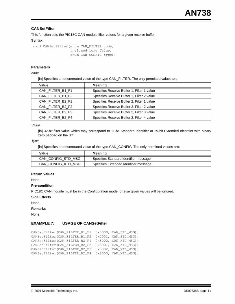
CANSetFilter
This function sets the PIC18C CAN module filter values for a given receive buffer.
Syntax
Parameters
code
[in] Specifies an enumerated value of the type CAN_FILTER. The only permitted values are:
Value
[in] 32-bit filter value which may correspond to 11-bit Standard Identifier or 29-bit Extended Identifier with binaryzero padded on the left.
Type
[in] Specifies an enumerated value of the type CAN_CONFIG. The only permitted values are:
Return Values
None.
Pre-condition
PIC18C CAN module must be in the Configuration mode, or else given values will be ignored.
Side Effects
None.
Remarks
None.
EXAMPLE 7: USAGE OF CANSetFilter
CANSetFilter(CAN_FILTER_B1_F1, 0x0000, CAN_STD_MSG);CANSetFilter(CAN_FILTER_B1_F2, 0x0001, CAN_STD_MSG);CANSetFilter(CAN_FILTER_B2_F1, 0x8000, CAN_XTD_MSG);CANSetFilter(CAN_FILTER_B2_F2, 0x8001, CAN_XTD_MSG);CANSetFilter(CAN_FILTER_B2_F3, 0x8002, CAN_XTD_MSG);CANSetFilter(CAN_FILTER_B2_F4, 0x8003, CAN_XTD_MSG);
Value Meaning
CAN_FILTER_B1_F1 Specifies Receive Buffer 1, Filter 1 value
CAN_FILTER_B1_F2 Specifies Receive Buffer 1, Filter 2 value
CAN_FILTER_B2_F1 Specifies Receive Buffer 2, Filter 1 value
CAN_FILTER_B2_F2 Specifies Receive Buffer 2, Filter 2 value
CAN_FILTER_B2_F3 Specifies Receive Buffer 2, Filter 3 value
CAN_FILTER_B2_F4 Specifies Receive Buffer 2, Filter 4 value
Value Meaning
CAN_CONFIG_STD_MSG Specifies Standard Identifier message
CAN_CONFIG_XTD_MSG Specifies Extended Identifier message
void CANSetFilter(enum CAN_FILTER code, unsigned long Value,enum CAN_CONFIG type);
2001 Microchip Technology Inc. DS00738B-page 11

AN738
MODULE OPERATION FUNCTIONS:
CANSendMessage
This function copies a given message to one of the empty transmit buffers and marks it as ready to be transmitted.
Syntax
Parameters
id
[in] 32-bit Identifier value, which may correspond to 11-bit Standard Identifier or 29-bit Extended Identifier withbinary zero padded on the left. The exact number of bits to use depends on the MsgFlags parameter.
Data
[in] Pointer to zero or more of data bytes to send.
DataLen
[in] Number of bytes to send.
MsgFlags
[in] Specifies an enumerated value of the type CAN_TX_MSG_FLAGS. This represents the logical AND of a Priorityvalue, an Identifier value, and a Message value (Priority AND Identifier AND Message). The possible values of allvariables are listed in the tables below:
Return Values
TRUE: If the given message was successfully placed in one of the empty transmit buffers.
FALSE: If all transmit buffers were full.
Pre-condition
None.
Side Effects
None.
Remarks
None.
Priority Value Meaning
CAN_TX_PRIORITY_0 Specifies Transmit Priority 0
CAN_TX_PRIORITY_1 Specifies Transmit Priority 1
CAN_TX_PRIORITY_2 Specifies Transmit Priority 2
CAN_TX_PRIORITY_3 Specifies Transmit Priority 3
Note: See the PIC18CXX8 data sheet for further details on transmit priority.
Identifier Value Meaning
CAN_TX_STD_FRAME Specifies Standard Identifier message
CAN_TX_XTD_FRAME Specifies Extended Identifier message
Message Value Meaning
CAN_TX_NO_RTR_FRAME Specifies Regular message - not RTR
CAN_TX_RTR_FRAME Specifies RTR message
void CANSendMessage(unsigned long id, BYTE *Data,BYTE DataLenenum CAN_TX_MSG_FLAGS MsgFlags);
DS00738B-page 12 2001 Microchip Technology Inc.

AN738
EXAMPLE 8: USAGE OF CANSendMessage
BYTE MessageData[1];// One byte to send…if ( CANIsTxReady() ){
MessageData[0] = 0x01;CANSendMessage( 0x02,
MessageData,1,CAN_TX_PRIORITY_0 &CAN_TX_STD_FRAME &CAN_TX_NO_RTR_FRAME);
}…
2001 Microchip Technology Inc. DS00738B-page 13

AN738
CANReceiveMessage
This function copies the new available message to one of the full receive buffers.
Syntax
Parameters
id
[out] 32-bit Identifier value, which may correspond to 11-bit Standard Identifier or 29-bit Extended Identifier withbinary zero padded on the left. The exact number of bits to use depends on the MsgFlags parameter.
Data
[out] Pointer to zero or more data bytes received.
DataLen
[out] Pointer to buffer to hold number of bytes received.
MsgFlags
[out] Specifies an enumerated value of the type CAN_RX_FILTER. This received value represents the logical ANDof a Buffer value and a Condition value (Buffer AND Condition). The possible values for all variables are listed inthe tables below:
If a flag bit is set, the corresponding meaning is TRUE; if cleared, the corresponding meaning is FALSE.
Note: Use CAN_RX_FILTER_BITS to access CAN_RX_FILTER_n bits.
Return Values
TRUE: If new message was copied to given buffer.
FALSE: If no new message was found.
Upon receiving the new message, buffers pointed to by id, Data, DataLen and MsgFlags are populated.
Pre-condition
The id, Data, DataLen and MsgFlags pointers must point to the desired and valid memory locations.
Side Effects
None.
Buffer Value Meaning
CAN_RX_FILTER_1 Specifies Receive Buffer Filter 1 caused this message to be accepted
CAN_RX_FILTER_2 Specifies Receive Buffer Filter 2 caused this message to be accepted
CAN_RX_FILTER_3 Specifies Receive Buffer Filter 3 caused this message to be accepted
CAN_RX_FILTER_4 Specifies Receive Buffer Filter 4 caused this message to be accepted
CAN_RX_FILTER_5 Specifies Receive Buffer Filter 5 caused this message to be accepted
CAN_RX_FILTER_6 Specifies Receive Buffer Filter 6 caused this message to be accepted
Condition Value Meaning
CAN_RX_OVERFLOW Specifies Receive Buffer overflow condition
CAN_RX_INVALID_MSG Specifies invalid message
CAN_RX_XTD_FRAME Specifies Extended Identifier message
CAN_RX_RTR_FRAME Specifies RTR message
CAN_RX_DBL_BUFFERED Specifies that this message was double buffered
void CANReceiveMessage( unsigned long *id, BYTE *Data,BYTE *DataLenenum CAN_RX_MSG_FLAGS *MsgFlags);
DS00738B-page 14 2001 Microchip Technology Inc.

AN738
Remarks
This function will fail if there are no new messages to read. Caller may check the return value to determine new messageavailability or may call CANIsRxReady function.
EXAMPLE 9: USAGE OF CANReceiveMessage
unsigned long NewMessage;BYTE NewMessageData[8];BYTE NewMessageLen;CAN_RX_MSG_FLAGS NewMessageFlags;BYTE RxFilterMatch;…if ( CANIsRxReady() ){
CANReceiveMessage(&NewMessage, NewMessageData, &NewMessageLen, &NewMessageFlags);
if ( NewMessageFlags & CAN_RX_OVERFLOW ){
// Rx overflow occurred}if ( NewMessageFlags & CAN_RX_INVALID_MSG ){
// Invalid message received}if ( NewMessageFlags & CAN_RX_XTD_FRAME ){
// Extended Identifier received}else{
// Standard Identifier received.}if ( NewMessageFlags & CAN_RX_RTR_FRAME ){
// RTR frame received}else{
// Regular frame received.}
RxFilterMatch = NewMessageFlags & CAN_RX_FILTER_BITS;}…
2001 Microchip Technology Inc. DS00738B-page 15

AN738
CANAbortAll
This function aborts all pending messages from the PIC18C CAN module. See the PIC18CXX8 data sheet for rulesregarding message abortion.
Syntax
Parameters
None.
Return Values
None.
Pre-condition
None.
Side Effects
None.
Remarks
None.
EXAMPLE 10: USAGE OF CANAbortAll
…CANAbortAll();…
void CANAbortAll();
DS00738B-page 16 2001 Microchip Technology Inc.

AN738
STATUS CHECK FUNCTIONS:
CANGetTxErrorCount
This function returns the PIC18C CAN transmit error count as defined by BOSCH CAN Specifications. See thePIC18CXX8 data sheet for more information.
Syntax
Parameters
None.
Return Values
Current value of transmit error count.
Pre-condition
None.
Side Effects
None.
Remarks
None.
EXAMPLE 11: USAGE OF CANGetTxErrorCount
BYTE TxErrorCount;…TxErrorCount = CANGetTxErrorCount();…
BYTE CANGetTxErrorCount();
2001 Microchip Technology Inc. DS00738B-page 17

AN738
CANGetRxErrorCount
This function returns the PIC18C CAN receive error count as defined by BOSCH CAN Specifications. See thePIC18CXX8 data sheet for more information.
Syntax
Parameters
None.
Return Values
Current value of receive error count.
Pre-condition
None.
Side Effects
None.
Remarks
None.
EXAMPLE 12: USAGE OF CANGetRxErrorCount
BYTE RxErrorCount;…RxErrorCount = CANGetRxErrorCount();…
BYTE CANGetRxErrorCount();
DS00738B-page 18 2001 Microchip Technology Inc.
AN738
CANIsBusOff
This function returns the PIC18C CAN bus On/Off state.
Syntax
Parameters
None.
Return Values
TRUE: If the PIC18C CAN module is in the Bus Off state.
FALSE: If the PIC18C CAN module is in the Bus On state.
Pre-condition
None.
Side Effects
None.
Remarks
None.
EXAMPLE 13: USAGE OF CANIsBusOff
…if ( CANIsBusOff() )
// CAN Module is off…
BOOL CANIsBusOff()
2001 Microchip Technology Inc. DS00738B-page 19

AN738
CANIsTxPassive
This function returns the PIC18C CAN transmit error status as defined by BOSCH CAN Specifications. See thePIC18CXX8 data sheet for more information.
Syntax
Parameters
None.
Return Values
TRUE: If the PIC18C CAN module is in transmit error passive state.
FALSE: If the PIC18C CAN module is not in transmit error passive state.
Pre-condition
None.
Side Effects
None.
Remarks
None.
EXAMPLE 14: USAGE OF CANIsTxPassive
…if ( CANIsTxPassive() )
// Transmit module is in passive state.…
BOOL CANIsTxPassive()
DS00738B-page 20 2001 Microchip Technology Inc.

AN738
CANIsRxPassive
This function returns the PIC18C CAN receive error status as defined by BOSCH CAN Specifications. See thePIC18CXX8 data sheet for more information.
Syntax
Parameters
None.
Return Values
TRUE: If the PIC18C CAN module is in receive error passive state.
FALSE: If the PIC18C CAN module is not in receive error passive state.
Pre-condition
None.
Side Effects
None.
Remarks
None.
EXAMPLE 15: USAGE OF CANIsRxPassive
…if ( CANIsRxPassive() )
// Rx is error passive, do something…
BOOL CANIsRxPassive()
2001 Microchip Technology Inc. DS00738B-page 21

AN738
CANIsRxReady
This function returns the PIC18C CAN receive buffer(s) readiness status.
Syntax
Parameters
None.
Return Values
TRUE: If at least one of the PIC18C CAN receive buffers is full.
FALSE: If none of the PIC18C CAN receive buffers are full.
Pre-condition
None.
Side Effects
None.
Remarks
None.
EXAMPLE 16: USAGE OF CANIsRxReady
unsigned long NewMessage;BYTE NewMessageData[8];BYTE NewMessageLen;enum CAN_RX_MSG_FLAGS NewMessageFlags;
…
if ( CANIsRxReady() )CANReceiveMessage(&NewMessage,
NewMessageData, &NewMessageLen, &NewMessageFlags);
…
BOOL CANIsRxReady()
DS00738B-page 22 2001 Microchip Technology Inc.

AN738
CANIsTxReady
This function returns the PIC18C CAN transmit buffer(s) readiness status.
Syntax
Parameters
None.
Return Values
TRUE: If at least one of the PIC18C CAN transmit buffers is empty.
FALSE: If none of the PIC18C CAN transmit buffers are empty.
Pre-condition
None.
Side Effects
None.
Remarks
None.
EXAMPLE 17: USAGE OF CANIsTxReady
BYTE MessageData[8];BYTE MessageLen;CAN_TX_MSG_FLAGS MessageFlags;…// Check to see if transmit buffer is readyif ( CANIsTxReady() ){
CANSendMessage(0x02, MessageData, MessageLen, MessageFlags);
}…
BOOL CANIsTxReady()
2001 Microchip Technology Inc. DS00738B-page 23
AN738
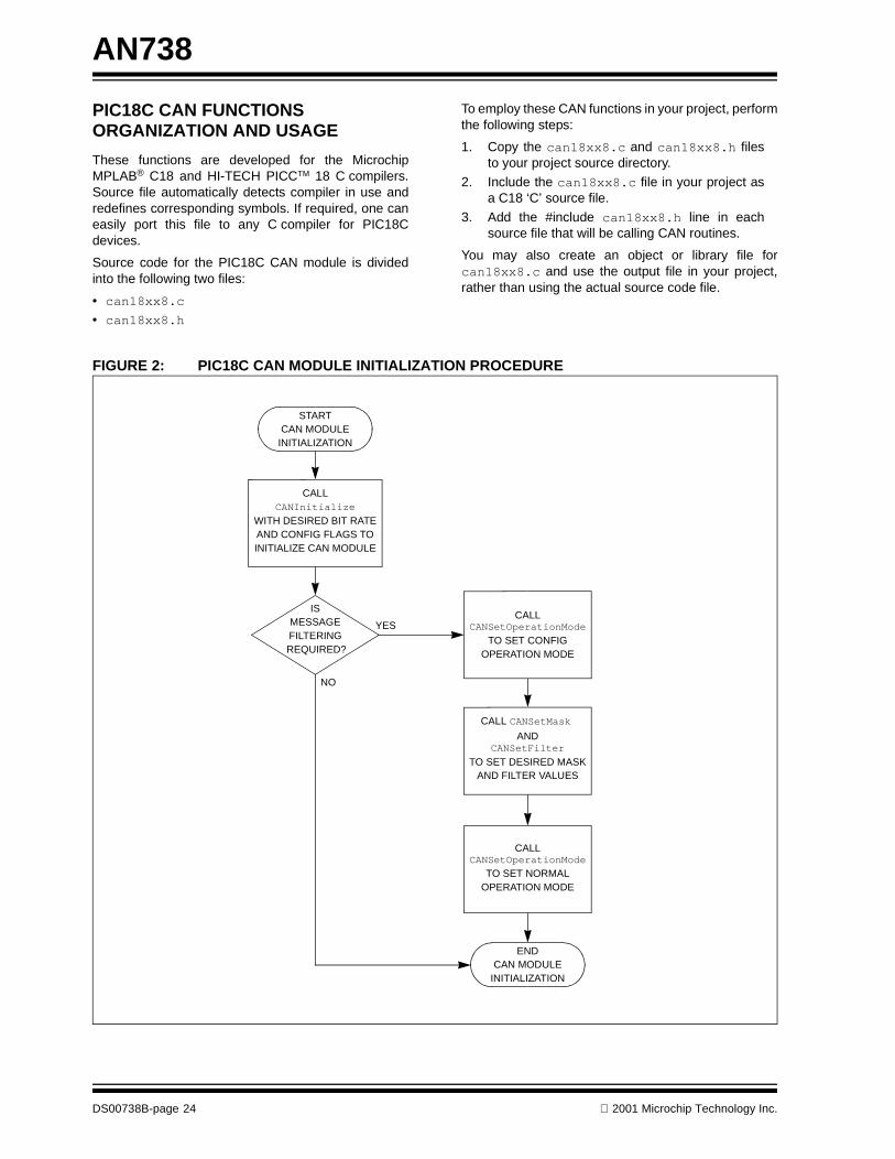
PIC18C CAN FUNCTIONS ORGANIZATION AND USAGE
These functions are developed for the MicrochipMPLAB® C18 and HI-TECH PICCTM 18 C compilers.Source file automatically detects compiler in use andredefines corresponding symbols. If required, one caneasily port this file to any C compiler for PIC18Cdevices.
Source code for the PIC18C CAN module is dividedinto the following two files:
• can18xx8.c • can18xx8.h
To employ these CAN functions in your project, performthe following steps:
1. Copy the can18xx8.c and can18xx8.h filesto your project source directory.
2. Include the can18xx8.c file in your project asa C18 ‘C’ source file.
3. Add the #include can18xx8.h line in eachsource file that will be calling CAN routines.
You may also create an object or library file forcan18xx8.c and use the output file in your project,rather than using the actual source code file.
FIGURE 2: PIC18C CAN MODULE INITIALIZATION PROCEDURE
STARTCAN MODULE
INITIALIZATION
CALL
INITIALIZE CAN MODULE
WITH DESIRED BIT RATEAND CONFIG FLAGS TO
CANInitialize
ISMESSAGE
REQUIRED?FILTERING
ENDCAN MODULE
INITIALIZATION
TO SET CONFIGOPERATION MODE
CALLCANSetOperationMode
TO SET DESIRED MASKAND FILTER VALUES
CALL CANSetMask AND
CANSetFilter
CALL
TO SET NORMALOPERATION MODE
CANSetOperationMode
NO
YES
DS00738B-page 24 2001 Microchip Technology Inc.

AN738
SAMPLE APPLICATION PROGRAM USING THE PIC18C CAN LIBRARY
An application program that uses the PIC18C CAN functions must follow certain initialization steps, as shown in Figure 2(see previous page).
EXAMPLE 18: SAMPLE APPLICATION PROGRAM 1
The following is a portion of a sample application program that requires all CAN Standard Identifier messages to beaccepted:
// Application specific variable declarations…
// CAN module related variablesunsigned long NewMessage;BYTE NewMessageData[8];Byte MessageData[8];BYTE NewMessageLen;CAN_RX_MSG_FLAGS NewMessageFlags;BYTE RxFilterMatch;
// Application specific initialization code follows…
// Initialize CAN module with no message filteringCANInitialize(SJW, BRP, PHSEG1, PHSEG2, PROPSEG, config);
// Main application loopwhile(1){
// Application specific logic here
// Check for CAN messageif ( CANIsRxReady() ){
CANReceiveMessage(&NewMessage, NewMessageData, &NewMessageLen, &NewMessageFlags);
if ( NewMessageFlags & CAN_RX_OVERFLOW ){
// Rx overflow occurred; handle it}if ( NewMessageFlags & CAN_RX_INVALID_MSG ){
// Invalid message received; handle it}if ( NewMessageFlags & CAN_RX_XTD_FRAME ){
// Extended Identifier received; handle it}else{
// Standard Identifier received.}if ( NewMessageFlags & CAN_RX_RTR_FRAME ){
// RTR frame received
2001 Microchip Technology Inc. DS00738B-page 25

AN738
}else{
// Regular frame received.}
// Extract receiver filter match, if it is to be usedRxFilterMatch = NewMessageFlags & CAN_RX_FILTER_BITS;
}
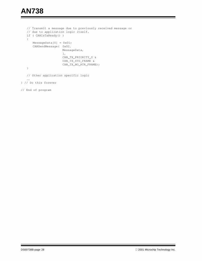
// Process received message…
// Transmit a message due to previously received message or // due to application logic itself.
if ( CANIsTxReady() ){
MessageData[0] = 0x01;CANSendMessage( 0x02,
MessageData, 1, CAN_TX_PRIORITY_0 & CAN_TX_STD_FRAME & CAN_TX_NO_RTR_FRAME);
}
// Other application specific logic…
} // Do this forever
// End of program
EXAMPLE 19: SAMPLE APPLICATION PROGRAM 2
The following is a portion of a sample application program that requires only a specific group of CAN Standard Identifiermessages to be accepted:
// Application specific variable declarations…
// CAN module related variablesunsigned long NewMessage;BYTE NewMessageData[8];Byte MessageData[8];BYTE NewMessageLen;CAN_RX_MSG_FLAGS NewMessageFlags;BYTE RxFilterMatch;
// Application specific initialization code follows…
// Initialize CAN module with no message filteringCANInitialize(SJW, BRP, PHSEG1, PHSEG2, PROPSEG, config);
// Set CAN module into configuration modeCANSetOperationMode(CAN_OP_MODE_CONFIG);
// Set Buffer 1 Mask value
DS00738B-page 26 2001 Microchip Technology Inc.

AN738
CANSetMask(CAN_MASK_B1, 0x0000000F, CAN_STD_MSG);
// Set Buffer 2 Mask valueCANSetMask(CAN_MASK_B2, 0x000000F0, CAN_STD_MSG);
// Set Buffer 1 Filter valuesCANSetFilter(CAN_FILTER_B1_F1, 0x00000001, CAN_CONFIG_STD_MSG);CANSetFilter(CAN_FILTER_B1_F2, 0x00000002, CAN_CONFIG_STD_MSG);CANSetFilter(CAN_FILTER_B2_F1, 0x00000010, CAN_CONFIG_STD_MSG);CANSetFilter(CAN_FILTER_B2_F2, 0x00000020, CAN_CONFIG_STD_MSG);CANSetFilter(CAN_FILTER_B2_F3, 0x00000030, CAN_CONFIG_STD_MSG);
// Main application loopwhile(1){
// Application specific logic here
// Check for CAN messageif ( CANIsRxReady() ){
CANReceiveMessage( &NewMessage, NewMessageData, &NewMessageLen, &NewMessageFlags );
if ( NewMessageFlags & CAN_RX_OVERFLOW ){
// Rx overflow occurred; handle it}if ( NewMessageFlags & CAN_RX_INVALID_MSG ){
// Invalid message received; handle it}if ( NewMessageFlags & CAN_RX_XTD_FRAME ){
// Extended Identifier received; handle it}else{
// Standard Identifier received.}if ( NewMessageFlags & CAN_RX_RTR_FRAME ){
// RTR frame received}else{
// Regular frame received.}
// Extract receiver filter match, if it is to be usedRxFilterMatch = NewMessageFlags & CAN_RX_FILTER_BITS;
}
// Process received message…
2001 Microchip Technology Inc. DS00738B-page 27
AN738
// Transmit a message due to previously received message or // due to application logic itself.if ( CANIsTxReady() ){
MessageData[0] = 0x01;CANSendMessage( 0x02,
MessageData, 1, CAN_TX_PRIORITY_0 & CAN_TX_STD_FRAME &
CAN_TX_NO_RTR_FRAME);}
// Other application specific logic…
} // Do this forever
// End of program
DS00738B-page 28 2001 Microchip Technology Inc.

AN738
CONCLUSION
The CAN library provided in this application note maybe used in any application program that needs a simplepolling mechanism to implement CAN communication.One can use this library as a reference to create a trueinterrupt-driven CAN communication driver.
APPENDIX A: SOURCE CODE
Because of its size, the complete source code for thisapplication note is not included in the text.
You may download the source code from the MicrochipWeb site, at the Internet address
www.microchip.com
2001 Microchip Technology Inc. DS00738B-page 29

AN738
NOTES:
DS00738B-page 30 2001 Microchip Technology Inc.

Note the following details of the code protection feature on PICmicro® MCUs.
• The PICmicro family meets the specifications contained in the Microchip Data Sheet.• Microchip believes that its family of PICmicro microcontrollers is one of the most secure products of its kind on the market today,
when used in the intended manner and under normal conditions.• There are dishonest and possibly illegal methods used to breach the code protection feature. All of these methods, to our knowl-
edge, require using the PICmicro microcontroller in a manner outside the operating specifications contained in the data sheet. The person doing so may be engaged in theft of intellectual property.
• Microchip is willing to work with the customer who is concerned about the integrity of their code.• Neither Microchip nor any other semiconductor manufacturer can guarantee the security of their code. Code protection does not
mean that we are guaranteeing the product as “unbreakable”.• Code protection is constantly evolving. We at Microchip are committed to continuously improving the code protection features of
our product.
If you have any further questions about this matter, please contact the local sales office nearest to you.
Information contained in this publication regarding deviceapplications and the like is intended through suggestion onlyand may be superseded by updates. It is your responsibility toensure that your application meets with your specifications.No representation or warranty is given and no liability isassumed by Microchip Technology Incorporated with respectto the accuracy or use of such information, or infringement ofpatents or other intellectual property rights arising from suchuse or otherwise. Use of Microchip’s products as critical com-ponents in life support systems is not authorized except withexpress written approval by Microchip. No licenses are con-veyed, implicitly or otherwise, under any intellectual propertyrights.
2001 Microchip Technology Inc.
Trademarks
The Microchip name and logo, the Microchip logo, FilterLab,KEELOQ, MPLAB, PIC, PICmicro, PICMASTER, PICSTART,PRO MATE, SEEVAL and The Embedded Control SolutionsCompany are registered trademarks of Microchip TechnologyIncorporated in the U.S.A. and other countries.
dsPIC, ECONOMONITOR, FanSense, FlexROM, fuzzyLAB,In-Circuit Serial Programming, ICSP, ICEPIC, microID,microPort, Migratable Memory, MPASM, MPLIB, MPLINK,MPSIM, MXDEV, PICC, PICDEM, PICDEM.net, rfPIC, SelectMode and Total Endurance are trademarks of MicrochipTechnology Incorporated in the U.S.A.
Serialized Quick Term Programming (SQTP) is a service markof Microchip Technology Incorporated in the U.S.A.
All other trademarks mentioned herein are property of theirrespective companies.
© 2001, Microchip Technology Incorporated, Printed in theU.S.A., All Rights Reserved.
Printed on recycled paper.
DS00738B - page 31
Microchip received QS-9000 quality system certification for its worldwide headquarters, design and wafer fabrication facilities in Chandler and Tempe, Arizona in July 1999. The Company’s quality system processes and procedures are QS-9000 compliant for its PICmicro® 8-bit MCUs, KEELOQ® code hopping devices, Serial EEPROMs and microperipheral products. In addition, Microchip’s quality system for the design and manufacture of development systems is ISO 9001 certified.
DS00738B-page 32 2001 Microchip Technology Inc.
MAMERICASCorporate Office2355 West Chandler Blvd.Chandler, AZ 85224-6199Tel: 480-792-7200 Fax: 480-792-7277Technical Support: 480-792-7627Web Address: http://www.microchip.comRocky Mountain2355 West Chandler Blvd.Chandler, AZ 85224-6199Tel: 480-792-7966 Fax: 480-792-7456
Atlanta500 Sugar Mill Road, Suite 200BAtlanta, GA 30350Tel: 770-640-0034 Fax: 770-640-0307Boston2 Lan Drive, Suite 120Westford, MA 01886Tel: 978-692-3848 Fax: 978-692-3821Chicago333 Pierce Road, Suite 180Itasca, IL 60143Tel: 630-285-0071 Fax: 630-285-0075Dallas4570 Westgrove Drive, Suite 160Addison, TX 75001Tel: 972-818-7423 Fax: 972-818-2924DaytonTwo Prestige Place, Suite 130Miamisburg, OH 45342Tel: 937-291-1654 Fax: 937-291-9175DetroitTri-Atria Office Building 32255 Northwestern Highway, Suite 190Farmington Hills, MI 48334Tel: 248-538-2250 Fax: 248-538-2260Kokomo2767 S. Albright Road Kokomo, Indiana 46902Tel: 765-864-8360 Fax: 765-864-8387Los Angeles18201 Von Karman, Suite 1090Irvine, CA 92612Tel: 949-263-1888 Fax: 949-263-1338New York150 Motor Parkway, Suite 202Hauppauge, NY 11788Tel: 631-273-5305 Fax: 631-273-5335San JoseMicrochip Technology Inc.2107 North First Street, Suite 590San Jose, CA 95131Tel: 408-436-7950 Fax: 408-436-7955Toronto6285 Northam Drive, Suite 108Mississauga, Ontario L4V 1X5, CanadaTel: 905-673-0699 Fax: 905-673-6509
ASIA/PACIFICAustraliaMicrochip Technology Australia Pty LtdSuite 22, 41 Rawson StreetEpping 2121, NSWAustraliaTel: 61-2-9868-6733 Fax: 61-2-9868-6755China - BeijingMicrochip Technology Consulting (Shanghai)Co., Ltd., Beijing Liaison OfficeUnit 915Bei Hai Wan Tai Bldg.No. 6 Chaoyangmen Beidajie Beijing, 100027, No. ChinaTel: 86-10-85282100 Fax: 86-10-85282104China - ChengduMicrochip Technology Consulting (Shanghai)Co., Ltd., Chengdu Liaison OfficeRm. 2401, 24th Floor, Ming Xing Financial TowerNo. 88 TIDU StreetChengdu 610016, ChinaTel: 86-28-6766200 Fax: 86-28-6766599China - FuzhouMicrochip Technology Consulting (Shanghai)Co., Ltd., Fuzhou Liaison OfficeRm. 531, North BuildingFujian Foreign Trade Center Hotel73 Wusi RoadFuzhou 350001, ChinaTel: 86-591-7557563 Fax: 86-591-7557572China - ShanghaiMicrochip Technology Consulting (Shanghai)Co., Ltd.Room 701, Bldg. BFar East International PlazaNo. 317 Xian Xia RoadShanghai, 200051Tel: 86-21-6275-5700 Fax: 86-21-6275-5060China - ShenzhenMicrochip Technology Consulting (Shanghai)Co., Ltd., Shenzhen Liaison OfficeRm. 1315, 13/F, Shenzhen Kerry Centre,Renminnan LuShenzhen 518001, ChinaTel: 86-755-2350361 Fax: 86-755-2366086Hong KongMicrochip Technology Hongkong Ltd.Unit 901-6, Tower 2, Metroplaza223 Hing Fong RoadKwai Fong, N.T., Hong KongTel: 852-2401-1200 Fax: 852-2401-3431IndiaMicrochip Technology Inc.India Liaison OfficeDivyasree Chambers1 Floor, Wing A (A3/A4)No. 11, O’Shaugnessey RoadBangalore, 560 025, IndiaTel: 91-80-2290061 Fax: 91-80-2290062
JapanMicrochip Technology Japan K.K.Benex S-1 6F3-18-20, ShinyokohamaKohoku-Ku, Yokohama-shiKanagawa, 222-0033, JapanTel: 81-45-471- 6166 Fax: 81-45-471-6122KoreaMicrochip Technology Korea168-1, Youngbo Bldg. 3 FloorSamsung-Dong, Kangnam-KuSeoul, Korea 135-882Tel: 82-2-554-7200 Fax: 82-2-558-5934SingaporeMicrochip Technology Singapore Pte Ltd.200 Middle Road#07-02 Prime CentreSingapore, 188980Tel: 65-334-8870 Fax: 65-334-8850TaiwanMicrochip Technology Taiwan11F-3, No. 207Tung Hua North RoadTaipei, 105, TaiwanTel: 886-2-2717-7175 Fax: 886-2-2545-0139
EUROPEDenmarkMicrochip Technology Nordic ApSRegus Business CentreLautrup hoj 1-3Ballerup DK-2750 DenmarkTel: 45 4420 9895 Fax: 45 4420 9910FranceMicrochip Technology SARLParc d’Activite du Moulin de Massy43 Rue du Saule TrapuBatiment A - ler Etage91300 Massy, FranceTel: 33-1-69-53-63-20 Fax: 33-1-69-30-90-79GermanyMicrochip Technology GmbHGustav-Heinemann Ring 125D-81739 Munich, GermanyTel: 49-89-627-144 0 Fax: 49-89-627-144-44ItalyMicrochip Technology SRLCentro Direzionale Colleoni Palazzo Taurus 1 V. Le Colleoni 120041 Agrate BrianzaMilan, Italy Tel: 39-039-65791-1 Fax: 39-039-6899883United KingdomArizona Microchip Technology Ltd.505 Eskdale RoadWinnersh TriangleWokingham Berkshire, England RG41 5TUTel: 44 118 921 5869 Fax: 44-118 921-5820
10/01/01
WORLDWIDE SALES AND SERVICE