Embed Size (px)
Citation preview

PL 800VM(RH,LH)
VERTICAL TURNING CENTER

PL 800VM 2016. 05
- 1 -
MACHINE CONSTRUCTION / FEATURES BED
The main spindle body of PL800V is consisted of one piece meehanite cast Iron bed, wide column, anti –heat displacement spindle and head stock.
Box way construction with anti-friction motion way surface that ensure unsurpassed long Term rigidity and superior accuracy.
Maximum rigidity and minimal deformation under heavy machining.
Three adjustable Gibs on X and Z axis provide easier maintenance as well as long term rigidity and accuracy.
SPINDLE & HEADSTOCK The machine headstock utilizes a precision ground spindle that is machined in a temperature-controlled environment and clean room assembled.
Spindle Nose ASA A2-11
Spindle Bore Dia. Ø 104
Spindle Speed (18” Chuck) Max 2,000 rpm
Spindle Drive Method Belt (*Gear)
Spindle Bearings I.D. (Front) Ø160
Front: Double Row Taper Roller Bearing (NN3032MBKRCC0P4 (NSK)) Front: Double Thrust Angular Ball Bearing (160TAC20XPN7+LC6 (NSK)) Rear: Double Row Taper Roller Bearing (NN3028MBKRCCPP4 (NSK))

PL 800VM 2016. 05
- 2 -
SPINDLE POWER-TORQUE DIAGRAM
The powerful Fanuc aiIP50/6000 (30/22kW) [*aiI30/6000 (37/30kW) + Gear box] spindle motor system will ensure heavy duty machining within a wide spindle speed range. MACHINE SPECIFICATIONS
Classification Unit PL800VM(RH,LH)
Capacity
Swing over the bed Ø 890
Swing over Cross slide Ø 740
Max. turning diameter Ø 810
Max. milling diameter Ø 624
Max. turning length Ø 775
Main Spindle
Max. spindle speed rpm 2,000
Spindle nose ASA A2-11
Spindle bearing hole diameter (Front) mm 160
Bearing type (Front) - Taper Roller Thrust Angular ball
Bearing type (Rear) - Taper Roller
Draw tube ID mm -
Spindle bore diameter mm 104
Maximum spindle torque [Opt.] N.m 1,158 [3,180]
Standard chuck size[Opt.] inch 18” [15",21",24"]

PL 800VM 2016. 05
- 3 -
Motor
Main Spindle Motor Model [Opt.] & Capacity (Cont./30min)
spec aiIP50/6000 [aiI30/6000]
kW 30/22 [37/30]
X axis Servo Motor Model & Capacity
spec aiF22/3000 kW 4
Z axis Servo Motor Model & Capacity
spec aiF40/3000B kW 9
Mill Spindle Model & Capacity (Cont./30min)
spec aiI6/10000
kW 5.5/7.5
Turret Index Motor Model & Capacity
spec βis12/3000
kW 1.8
Feed system
X axis travel mm 430
Z axis travel mm 800
Angle of slant bed deg Vertical
X axis guideway span mm 430
Z axis guideway span mm 650
Tailstock(B axis) guideway span[Opt.] mm -
X axis rapid traverse rate m/min 20
Z axis rapid traverse rate m/min 20
Maximum X axis feed thrust N 36,191
Maximum Z axis feed thrust N 73,513
X axis diameter mm 40
X axis lead mm 10
Z axis diameter mm 50
Z axis lead mm 10
Turret
Max. number of tool [Opt.] st. 12[BMT75]
Turning tool shank size mm 32
Boring bar diameter Ø 63
Turret index time s 0.15
Rotary tool spindle speed rpm 4,000
Tool selection - Random
Curvic coupling diameter mm 200
Turret clamping force (at 35bar) N 56,077
Turret driving - Servo motor
Coolant Coolant pump pressure bar 4.5
Coolant pump motor kW 0.9
Coolant tank capacity ℓ 300
Hydraulic Hydraulic tank capacity ℓ 50
Max. hydraulic pressure bar 50

PL 800VM 2016. 05
- 4 -
Lubrication tank capacity ℓ 3
Machine Weight kgf 11,200
Floor Space (length x width) [with Chip Conveyor & Coolant tank] mm
2,050x2,822 [SIDE : 3,311 x 2,822] [REAR : 2,050 x 3,539]
Height mm 3,491
Voltage Required V 220
Power Requirement Kva 53(*61)
NC - F 0i-TD
CONTROLLER - Fanuc Oi-TD
- High-Speed and High Quality Machining Excellent Control Functions 实现高速、高质量的加工强大的控制功能 - Focusing on Minimizing Downtime High Reliability and Easy Maintenance 追求更便于使用丰富的 CNC 功能和优异的操作性
TOOL PRESETTER [Opt.] MANUAL TOOL PRESETTER (Removable TYPE)
Manual Tool presetter serves as a monitoring system for tool wear compensation and tool-breakage detection
TOOL SETTING
Tool setting data is registered to the CNC by simply bringing the tool tip into contact with the tool sensor.
TOOL PRESETTER FOR PRODUCTIVITY Reduced set-up time Reduced change over time from part to part Reduced time due to worn inserts or broken tools

PL 800VM 2016. 05
- 5 -
RIGID TURRET DESIGN <Servo motor Driven>
The 12-station turret accepts any combination of I.D. or O.D. tool holders. Turret rotation is bi-
directional and non-stop from station to station.
The design incorporates a high accuracy coupling, with random selection and shortest path indexing. This reduces idle time, contributing to increased productivity
Turret Type 12 Drum, 12 position turret Turret Drive Method Servo Motor βis 12/3000 Turret milling motor aiI6/10000 5.5/7.5 kw Milling Spindle Speed 4,000 RPM Tool Size
- Turning/Face holder (wedge clamp) BMT75 - □32x32 mm - Boring bar shank Dia. BMT75 - Ø 63 mm
Index Coupling “Curvic” Coupling
Ø 200mm 3-piece lifting type
Turret Clamp Force by Hydraulic 5,722 kgf (56,077 N) Turret Index Time (1 step) 0.15 s

PL 800VM 2016. 05
- 6 -
HYDRAULIC CHUCK & CYLINDER Chuck Type HC18A11V-22T-SM (SAMCHUNLLY) Matching Soft / Hard Jaw SB15N1/HB15N1 Jaw Stroke Diameter Ø16 mm Max. Speed of Chuck 2,000 rpm Spindle Nose A2-11 Chuck Cylinder Type YH-20135RE (SAMCHUNLLY) Cylinder Ability Max. Allowable Pressure 40.8 kg / cm2 (40 bar) Thrust (Push / Pull) 11,573 kgf / 10,738 kgf (114 KN / 105 KN)
BALL SCREW
• X Axis : YEF4010-R632-C3-963
(TIC) • Z Axis : YEF5010-R1007-C3-1322
(TIC)
LUBRICATION
Pump unit AMZ-III-1-3 (LUBE) Motor 19W AC100V x 50 /
60 Hz Discharge flow rate 0.09 / 0.11 L/min Discharge pressure 15 kgf/㎠
Tank capacity 3 Liters

PL 800VM 2016. 05
- 7 -
COOLANT AND CHIP PAN Type Removable / Independent Discharge & Pressure 300 L/min
4.5 kg/cm2 at 60 Hz
MACHINE LAYOUT
800VM(RH)

PL 800VM 2016. 05
- 8 -
800VM(LH)

PL 800VM 2016. 05
- 9 -
TOOL INTERFERENCE
PL800VM(RH)
PL800VM(LH)

PL 800VM 2016. 05
- 10 -
MACHINE SPECIFICATIONS
CAPACITY Maximum Swing (on the Bed) Ø890mm Turning Diameter (Max.) Ø810mm Maximum Turning Length 800mm Chuck Size 18 ” standard (*15, 21, 24”)
SPINDLE Spindle Nose A2-11 (ASA) Bore Diameter Ø104 Main Spindle Motor (Opt.) 30 / 22 kW (*37/30 kW) Spindle Speed 2,000 rpm with 18” chuck
Spindle Torque (Opt.) 1,158 N.m (*3,180 N.m)
SLIDE & CARRIAGE "X" Axis Travel 430 mm "Z" Axis Travel 800 mm Rapid Traverse "X" 20 m/min Rapid Traverse "Z" 20 m/min Slide Ways (X / Z) Box guide
TURRET Number of Tool Stations 12 Tools [BMT75] Turret Indexing Speed (Full) 0.15 s Tool Size (Turning and Facing) □32x32 Tool Size (Boring Bar Max. Diameter) Ø63 mm
MACHINE SIZE Floor Space Requirements (L x W) 2,050 x 2,822 Machine Weight 11,200 kg Power Consumption 53kVA(*61kVA) Voltage 220V±10%, 60 Hz, 3 phase
CNC CNC Model Fanuc 0i-TD
Display Unit 10.4” TFT LCD Color Monitor

PL 800VM 2016. 05
- 11 -
STANDARD EQUIPMENT
10.4”TFT LCD Color Monitor Machine Work Light Complete Coolant System(4.5bar-60Hz) : Tank capacity 300 Liters Shower Coolant unit (1.5bar-60Hz) Splash Guard with rear coolant tank (Full Coverage) 18 Inch Dia. Hydraulic Solid Chuck Package:
- Samchully with One (1) set of hard jaws, Three (3) set of soft jaws Hydraulic Unit: 3.7 kW Pump, 50 liter Tank, 50 kg/cm2 (50 bar) 12Drum - 12 Position Turret Lubrication System Front Door Interlock Machine Arranged for 220V + 10%, 60Hz One (1) set of Adjusting Tools Manuals: One (1) each (Programming, Operating, Part List, Electric circuit diagrams) 12D 12P Turret Standard Tooling Pack. Safety precaution name plate Leveling Unit Chuck Clamp foot switch Chuck Clamp confirmation Chuck pressure switch Main spindle orientation Standard tool
- Face holder 1ea - O.D holder 4ea - Boring bar holder 2ea - Straight milling head tool holder 2ea - Angular milling head tool holder 2ea - U-drill holder 1ea - Boring bar sleeve: Ø50 1ea - Boring bar sleeve: Ø40 1ea - Boring bar sleeve: Ø32 1ea - Boring bar sleeve: Ø25 1ea - Boring bar sleeve: Ø20 1ea - Boring bar sleeve: Ø16 1ea - Drill socket MT3,MT4,MT5 1ea -

PL 800VM 2016. 05
- 12 -
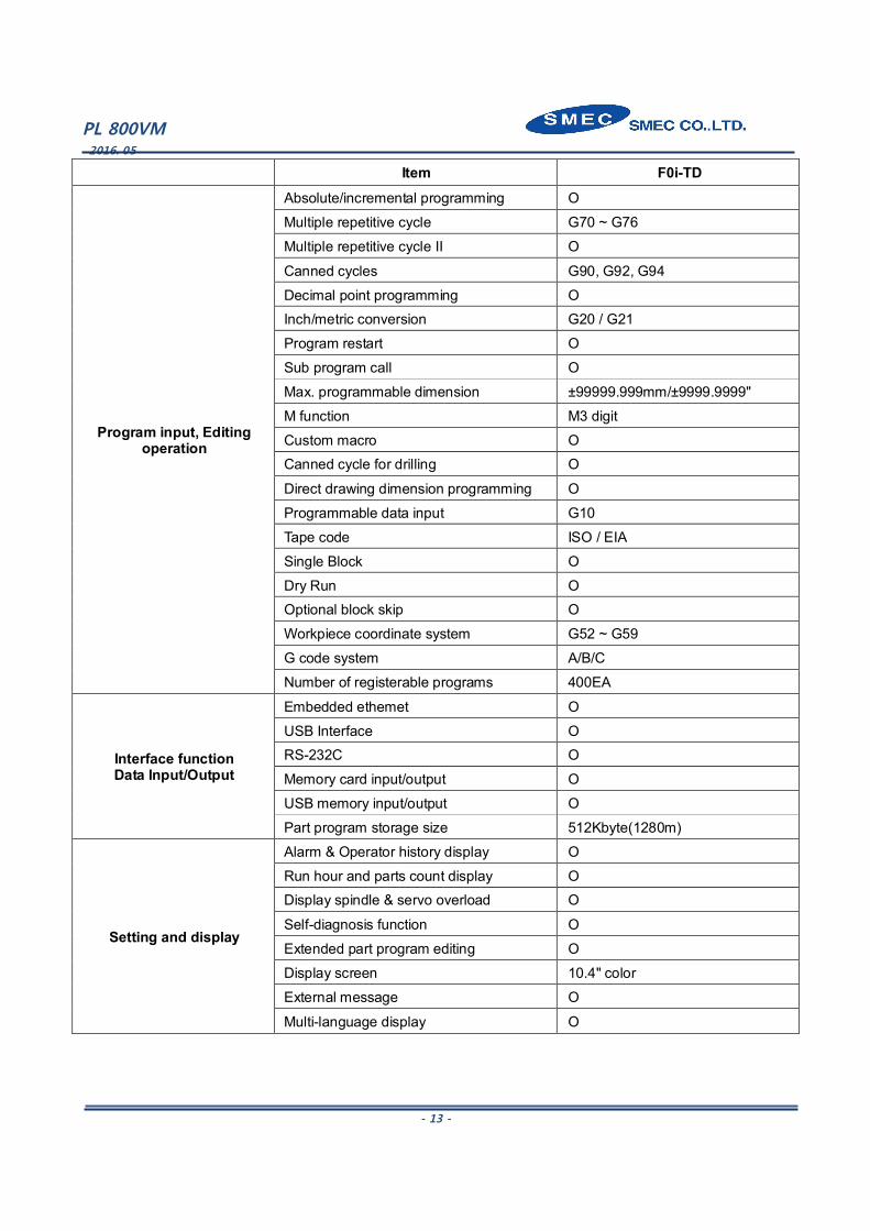
CONTROL SPECIFICATIONS
Item F0i-TD
Controlled axis
Controlled axes 2(X,Z)
Cs contouring control 1(C) (PL 800VM Only)
Max. simultaneously controlled axis 4
Least command increment 0.001mm / 0.0001"
Chuck and tail stock barrier O
Stored stroke check 1 O Stored stroke check 2,3 O
Interpolation/Feed functions
Linear interpolation G01
Circular interpolation G02, G03
Dwell G04
Polar cordinate interpolation G12.1, G13.1
Cylindrical interpolation G07.1 Polygon machining with two spindles G50.2, G51.2 (PL 800VM Only)
Variable lead thread cutting G34
Continuous threading O
Reference position return G28
Reference position return check G27
2nd/3rd/4th reference position return G30 Rapid traverse rate override F0, 25%, 50%, 100%
Feedrate override 0 ~ 150%
Jog Override O
Pulse handle feed X1, X10, X100
Feedrate per minute G98
Feedrate per revolution G99
Spindle function Spindle orientation M19
Rigid tapping M28
Spindle override 50 ~ 150%
Tool functions
Tool number command T4-Digt
Tool nose radius compensation G40 ~ G42
Tool offset pairs 64 Tool geometry/wear offset O
Tool life management O
Tool path graphic display O
Automatic tool offset O Direct input of tool offset value measured B O
PL 800VM 2016. 05
- 13 -
Item F0i-TD
Program input, Editing operation
Absolute/incremental programming O
Multiple repetitive cycle G70 ~ G76
Multiple repetitive cycle II O
Canned cycles G90, G92, G94
Decimal point programming O Inch/metric conversion G20 / G21
Program restart O
Sub program call O
Max. programmable dimension ±99999.999mm/±9999.9999"
M function M3 digit
Custom macro O Canned cycle for drilling O
Direct drawing dimension programming O
Programmable data input G10
Tape code ISO / EIA
Single Block O
Dry Run O Optional block skip O
Workpiece coordinate system G52 ~ G59
G code system A/B/C
Number of registerable programs 400EA
Interface function Data Input/Output
Embedded ethemet O
USB Interface O RS-232C O
Memory card input/output O
USB memory input/output O
Part program storage size 512Kbyte(1280m)
Setting and display
Alarm & Operator history display O
Run hour and parts count display O Display spindle & servo overload O
Self-diagnosis function O
Extended part program editing O
Display screen 10.4" color
External message O
Multi-language display O

PL 800VM 2016. 05
- 14 -
OPTIONAL EQUIPMENT Auto Door
External Work Counter
Linear scale (X/Z axis)
3 Step Patrol Lamp
High Pressure Coolant (7, 10, 14.5, 20 bar - 60Hz)
Chip Conveyor (Rear, Side type)
Chip Bucket
Chuck Air Blower
Tool Presetter(manual type)
Spindle gear box(2 step)
Air blower
Special Chuck
Air gun
Oil skimmer
Dual pressure chucking
Chuck coolant
Coolant gun
Coolant chiller
Coolant pressure switch
Coolant level switch
Mist collector
Soft Jaw (1 set, 3 each)
Hard Jaw (1 set, 3 each)
Transformer
Face holder
O.D holder
Straight milling head tool holder
Angular milling head tool holder
U-drill holder
Boring Bar Holder 63(2-1/2”)
Boring Bar Sleeve 50(2”)
Boring Bar Sleeve 45(1-1/2”)
Boring Bar Sleeve 32(1-1/4”)
Boring Bar Sleeve 25(1”)
Boring Bar Sleeve 20(3/4”)
Boring Bar Sleeve 16(5/8”)
Drill Socket (MT#3, MT#4 MT#5,)

PL 800VM 2016. 05
- 15 -
STANDARD TERMS AND CONDITIONS
Warranty The machine is warranted against defects in parts, material and workmanship for a period of twelve months after the date of installation. The control, servomotors and main spindle motor are warranted against defects in parts, material and workmanship for a period of twenty-four months after the date of installation. Installation Installation of the machine/control system is supervised by SMEC factory trained servicemen without charge to customer. Initial training on machine/control operation and programming will also be done at the time of the machine installation. Additional training in N/C programming will be available on a scheduled basis. Delivery Free on Board, Port of Entry, Duty paid, approximately two to four months upon receipt of firm purchase order with down payment. Payment Terms L/C AT SIGHT from the date of shipment from port. Thank you for the opportunity to quote your machining needs with the SMEC PL800VM Horizontal Turning Centers. After an examination of this quotation, should you have any questions, or desire additional information, please do not hesitate to contact us.
Sincerely,