Embed Size (px)
Citation preview
LASERTEC 40
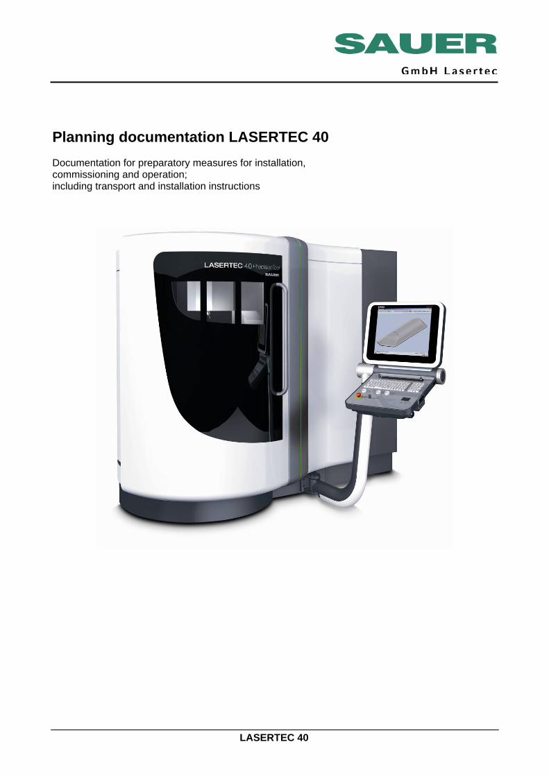
Planning documentation LASERTEC 40 Documentation for preparatory measures for installation, commissioning and operation; including transport and installation instructions
LASERTEC 40
All rights, also to reprinting, duplication of parts of this manual and to translation are reserved by the publisher. It is not allowed to reproduce or copy using electronic data processing systems, any part of this manual in any form, including for training or educational purposes, without the written approval of the publisher. The version in the manufacturer's language (German) is definitive for the technical content. Issue: 02/10 Ident no.: 2586320*PU*LT40*GB*8124 ©2010 SAUER GmbH
Planning, transport, installation
LASERTEC 40 Page 2
Foreword Dear customer, We are pleased you have decided for an Lasertec machine.
Some of the details on your Lasertec machine may vary from the illustrations in this manual. However, this situation will have no effect on the operation of the machine. If you have any questions on this machine manual, or you want to re-order the booklet, please state the order no.
A few instructions for your safety It is imperative this machine manual is followed for the safe operation
of the machine. Ensure the manual is available at the machine. Nobody without the necessary training - whether provided internally, by a training organisation or directly by SAUER GmbH - is allowed to operate the machine, even for a short time. Read the general health and safety regulations published by the related authorities. If the regulations are not hung on the notice board in your organisation, ask the responsible safety officer. Follow the instructions for correct use on the following pages. A brochure is supplied with every machine manual; this brochure contains important instructions on health and safety on Lasertec machines. Read this brochure before you work on an Lasertec machine for the first time. Close the splash protection feature before you start machining. Machines that are used in the automatic mode must always be equipped with a splash protection feature.
Changes We reserve the right make changes to the design, features and
accessories in the interest of further development. It is therefore not possible to derive any claims from the information, illustrations and descriptions. Errors excepted. We wish you every success! SAUER GmbH
Planning, transport, installation
LASERTEC 40 Page 3
Planning What is the purpose of this documentation? Basics This documentation is aimed at the people responsible for installing the
machine and their staff. Contained in this documentation is all the information necessary for the preparation of the machine's installation location and its surroundings such that the machine can be installed immediately on delivery. Information on the transport of the machine to the place it is to be installed is also included. Please also note the information on the tools and lubricants necessary.
Initial commissioning The machine is only allowed to be initially commissioned by a person
authorised by the machine manufacturer. Otherwise, SAUER will accept no liability whatsoever for any damage or malfunctions that may occur.
Effective utilisation of the machine Training courses SAUER provides training and further training for specialist personnel as a
service. Whether the machine’s features are actually utilised depends on the user’s qualifications. For this reason, clarify in good time whether your staff has the necessary knowledge. Plan your training course dates such that all training measures are complete before the delivery of the machine.
Notes for your planning Planning The floor area mentioned in this documentation applies only to the
machines with the peripheral equipment as shown. For information on the floor area and space required by the options you have ordered, please refer to the related installation diagrams.
The machine documentation is applicable independent of the information in this documentation.
Planning, transport, installation
LASERTEC 40 Page 4
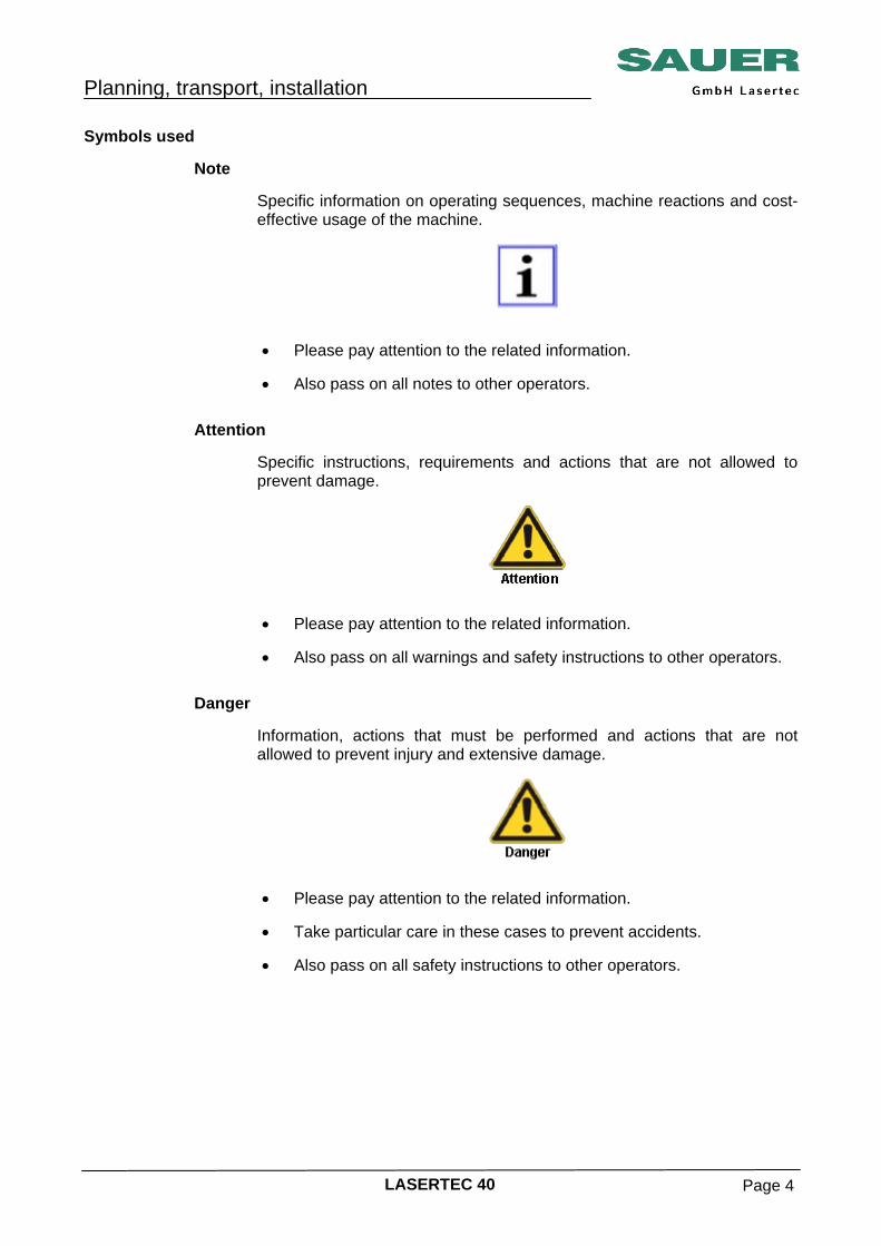
Symbols used Note Specific information on operating sequences, machine reactions and cost-
effective usage of the machine.
• Please pay attention to the related information.
• Also pass on all notes to other operators.
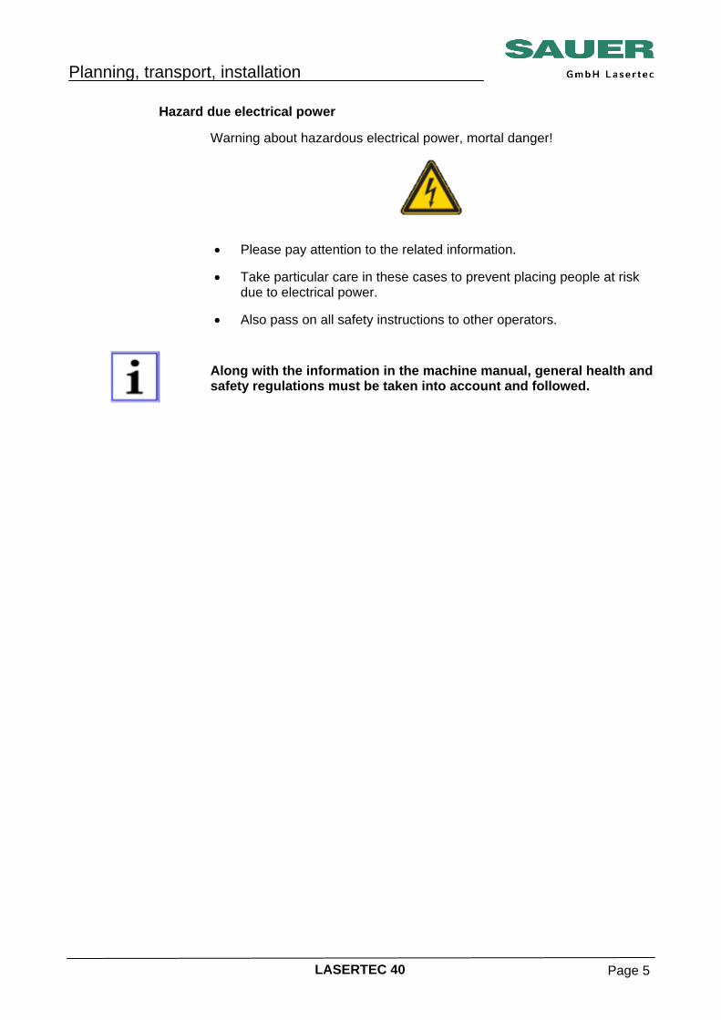
Attention Specific instructions, requirements and actions that are not allowed to
prevent damage.
• Please pay attention to the related information.
• Also pass on all warnings and safety instructions to other operators.
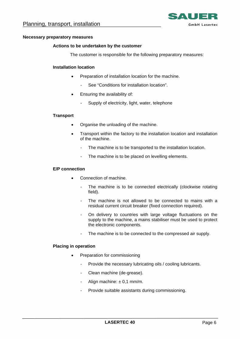
Danger Information, actions that must be performed and actions that are not
allowed to prevent injury and extensive damage.
• Please pay attention to the related information.
• Take particular care in these cases to prevent accidents.
• Also pass on all safety instructions to other operators.
Planning, transport, installation
LASERTEC 40 Page 5
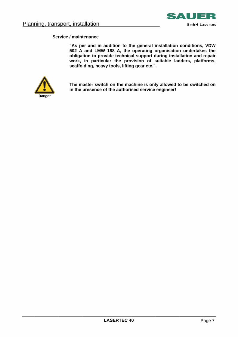
Hazard due electrical power Warning about hazardous electrical power, mortal danger!
• Please pay attention to the related information.
• Take particular care in these cases to prevent placing people at risk
due to electrical power. • Also pass on all safety instructions to other operators.
Along with the information in the machine manual, general health and safety regulations must be taken into account and followed.
Planning, transport, installation
LASERTEC 40 Page 6
Necessary preparatory measures Actions to be undertaken by the customer The customer is responsible for the following preparatory measures: Installation location • Preparation of installation location for the machine. - See “Conditions for installation location”. • Ensuring the availability of: - Supply of electricity, light, water, telephone Transport • Organise the unloading of the machine.
• Transport within the factory to the installation location and installation
of the machine. - The machine is to be transported to the installation location. - The machine is to be placed on levelling elements. E/P connection • Connection of machine. - The machine is to be connected electrically (clockwise rotating
field).
- The machine is not allowed to be connected to mains with a residual current circuit breaker (fixed connection required).
- On delivery to countries with large voltage fluctuations on the
supply to the machine, a mains stabiliser must be used to protect the electronic components.
- The machine is to be connected to the compressed air supply.
Placing in operation • Preparation for commissioning - Provide the necessary lubricating oils / cooling lubricants.
- Clean machine (de-grease).
- Align machine: ± 0,1 mm/m.
- Provide suitable assistants during commissioning.
Planning, transport, installation
LASERTEC 40 Page 7
Service / maintenance "As per and in addition to the general installation conditions, VDW
502 A and LMW 188 A, the operating organisation undertakes the obligation to provide technical support during installation and repair work, in particular the provision of suitable ladders, platforms, scaffolding, heavy tools, lifting gear etc.".
The master switch on the machine is only allowed to be switched on in the presence of the authorised service engineer!
Planning, transport, installation
LASERTEC 40 Page 8
Installation location Customer information It is imperative this information is checked prior to the delivery of the
machine, safeguarded and implemented.
The responsibility for the correct location of the machine lies with the customer. The customer is entirely responsible for a suitable installation location. If problems should arise later due to failure to follow the information provided, SAUER cannot be held responsible.
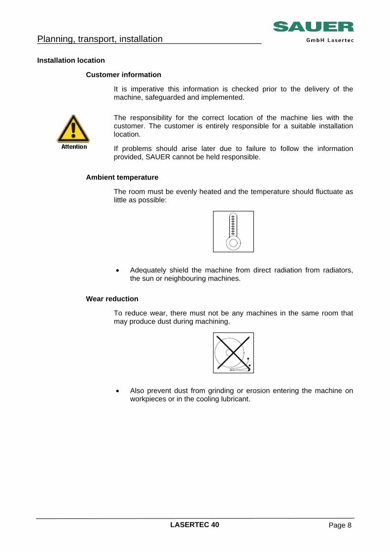
Ambient temperature The room must be evenly heated and the temperature should fluctuate as
little as possible:
• Adequately shield the machine from direct radiation from radiators,
the sun or neighbouring machines. Wear reduction To reduce wear, there must not be any machines in the same room that
may produce dust during machining.
• Also prevent dust from grinding or erosion entering the machine on
workpieces or in the cooling lubricant.
Planning, transport, installation
LASERTEC 40 Page 9
Corrosion prevention To prevent corrosion on the workpiece and machine, the installation
location must be dry and free of aggressive vapours:
• No soldering, welding, painting, pickling or electroplating systems in
the same room. Foundation A suitable bearing plate approved by a structural engineer is required.
• The bearing plate must not have any expansion joints in the area
covered by the machine. • Cracks, cable ducts or other interruptions are not allowed in the area
covered by the machine. • Place the machine on a firm floor that will provide a stable base for
the machine. • The machine must be level and remain so to ensure the accuracy of
the machine. • The floor must not give so that the machine remains exactly aligned.
Planning, transport, installation
LASERTEC 40 Page 10
Load bearing capacity Ensure the floor has adequate load bearing capacity.
• Have the load bearing capacity checked by a structural engineer. Have the structural engineer determine in a binding manner • That the load bearing capacity of the floor, the cellar roof or
intermediate storey, including its substructure, is adequate (also in older buildings).
• That the building regulations are met.
Note that the centre of gravity moves due to the weight of the workpieces and travels.
Maximum weight Take the load bearing capacity of the floor into account
• The maximum installation weight for the machine and also the
maximum weight of tool and accessory cabinets including contents,
- Workpieces and devices,
- People,
- Transport equipment,
- Other features in the immediate vicinity of the machine.
Planning, transport, installation
LASERTEC 40 Page 11
Cellar roofs, intermediate floors In case of installation of the machine on cellar roofs, intermediate floors or
other load bearing structures:
Have a structural engineer experienced in structural dynamics determine
in a binding manner, as per DIN 4024 part 1: Flexible structures that support machines with rotating elements, • That the load bearing structure is able to absorb the actions of the
machine's inertial forces, • or, if this validation cannot be provided, that the measures for
vibration damping that are then to be required are adequate. Floor vibration Floor vibration or shocks from neighbouring machines or other sources
must not affect the function and accuracy of the machine.
Planning, transport, installation
LASERTEC 40 Page 12
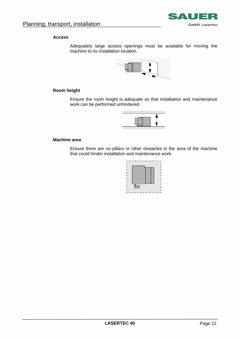
Access Adequately large access openings must be available for moving the
machine to its installation location.
Room height Ensure the room height is adequate so that installation and maintenance
work can be performed unhindered.
Machine area Ensure there are no pillars or other obstacles in the area of the machine
that could hinder installation and maintenance work.
Planning, transport, installation
LASERTEC 40 Page 13
Ambient conditions for the machine • Permissible ambient temperature: +15° to + 35° C
• Maximum installation height: 1000 m above sea level
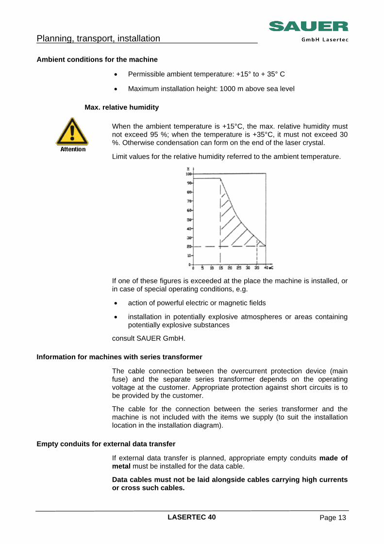
Max. relative humidity
When the ambient temperature is +15°C, the max. relative humidity must not exceed 95 %; when the temperature is +35°C, it must not exceed 30 %. Otherwise condensation can form on the end of the laser crystal.
Limit values for the relative humidity referred to the ambient temperature.
If one of these figures is exceeded at the place the machine is installed, or in case of special operating conditions, e.g.
• action of powerful electric or magnetic fields
• installation in potentially explosive atmospheres or areas containing potentially explosive substances
consult SAUER GmbH.
Information for machines with series transformer The cable connection between the overcurrent protection device (main
fuse) and the separate series transformer depends on the operating voltage at the customer. Appropriate protection against short circuits is to be provided by the customer.
The cable for the connection between the series transformer and the machine is not included with the items we supply (to suit the installation location in the installation diagram).
Empty conduits for external data transfer If external data transfer is planned, appropriate empty conduits made of
metal must be installed for the data cable.
Data cables must not be laid alongside cables carrying high currents or cross such cables.
Planning, transport, installation
LASERTEC 40 Page 14
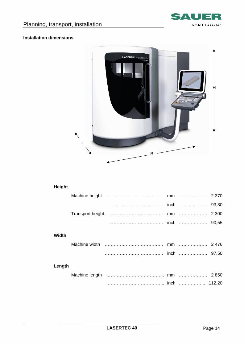
Installation dimensions
Height Machine height ……………………………….. mm ………………. 2 370 ……………………………….. inch ………………. 93,30 Transport height ……………………………… mm ………………. 2 300 ……………………………… inch ………………. 90,55 Width Machine width …………………………………. mm ………………. 2 476 …………………………………. inch ………………. 97,50 Length Machine length ………………………………... mm ………………. 2 850
………………………………... inch ……………... 112,20
H
B
L
Planning, transport, installation
LASERTEC 40 Page 15
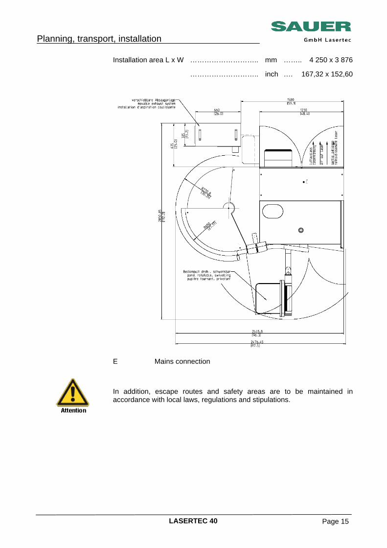
Installation area L x W ……………………….. mm …….. 4 250 x 3 876 ……………………….. inch …. 167,32 x 152,60
E Mains connection
In addition, escape routes and safety areas are to be maintained in accordance with local laws, regulations and stipulations.
Planning, transport, installation
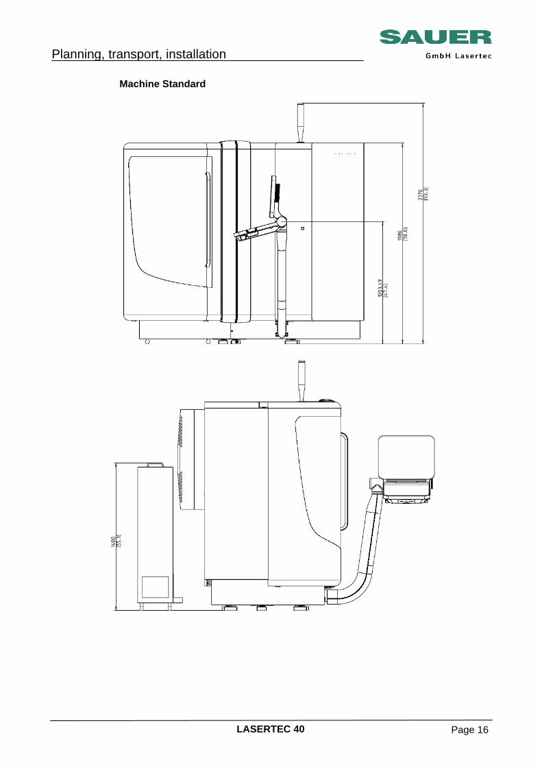
LASERTEC 40 Page 16
Machine Standard
Planning, transport, installation
LASERTEC 40 Page 17
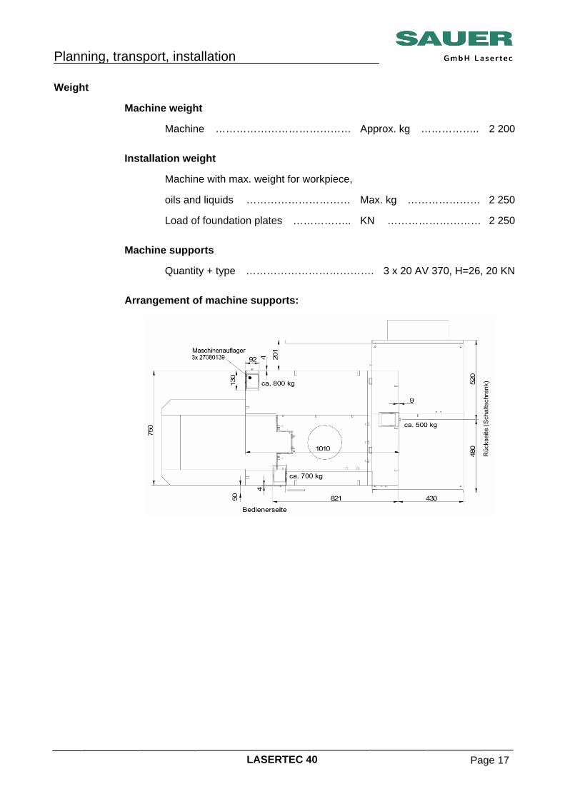
Weight Machine weight Machine ………………………………… Approx. kg …………….. 2 200 Installation weight Machine with max. weight for workpiece, oils and liquids ………………………… Max. kg ………………… 2 250 Load of foundation plates …………….. KN ……………………… 2 250 Machine supports Quantity + type ………………………………. 3 x 20 AV 370, H=26, 20 KN Arrangement of machine supports:

Planning, transport, installation
LASERTEC 40 Page 18
Installation data Electrical supply
During the electrical installation attention is to be paid to ensuring EN 60 204, part 1, point 6.3.3 "Protection by automatic interruption of the power supply" is met. On this topic also see IEC 364-4-41 (DIN 57 100, VDE 0100, part 410). The machine is not allowed to be connected to mains with a residual current circuit breaker, see EN 50178, point 5.3.2.3 (old VDE 0160, point 5.5.3.4.2). As our machine has a leakage current higher than 3.5 mA AC due to EMC measures, it must have a fixed connection. In addition, one of the measures stated below must be taken, according to EN 50178, point 5.3.2.1 (old VDE 0160, point 5.5.3.4.1 and 5.5.3.4.2).
• Earth conductor cross section at least 25 mm² Cu.
• Monitoring of the earth conductor by a device that will automatically
shut down the electronic equipment in the event of a fault. • Laying of a second conductor, electrically in parallel with the earth
conductor, using separate terminals. This conductor alone must comply with the requirements of section 543 of the harmonisation document (HD) 384.5.54 S1 (old DIN VDE 0100 part 540) for earth conductors.
The machine can be operated on a 400 V TN supply without a series isolating transformer.
Planning, transport, installation
LASERTEC 40 Page 19
Connection ratings Machine connection: TN-S supply with 3 conductors (L1, L2, L3) as well as neutral conductor (N)
and earth conductor (PE). Mains connection ………………… 3N/PE~50/60 Hz …….. 400/230 V Open cable length above floor …... m ……………………………… 0,8 Connecting cable cross-section …………… accd. to DIN 5710/VDE 0100 * Due to energy return and possible operation for short periods, currents
may occur that make the recommended mains fuse protection necessary. In max. at
100% ED A
Power consumption at 100% ED,
KVA
Max. fusing A
Basic version 40 27 50
Planning, transport, installation
LASERTEC 40 Page 20
Transport Transport instructions General instructions These transport instructions provide information on the attachment of
transport equipment and tackle as well as on the safe transport of pallet, crate and machine. If a machine already installed is to be moved to a different place, the machine must be carefully prepared for the transport (see Transport preparation). Dismantling and transport preparation can also be undertaken by our customer service.
Transport safety
During the transport of the machine there is a risk of accident due to material fracture, tipping, slipping or the machine falling! • Follow transport instructions, safety instructions, health and safety
regulations and local stipulations! • Only use suitable, undamaged and fully functional transport
equipment with suitable carrying capacity! • Follow the related safety instructions and note the transport
dimensions (see "Technical information"). • Pay attention to the markings for points for connecting tackle and the
centre of gravity. • Provide a clear transport path to prevent the risk of crushing.
• Never stand under suspended loads: mortal danger!
Planning, transport, installation
LASERTEC 40 Page 21
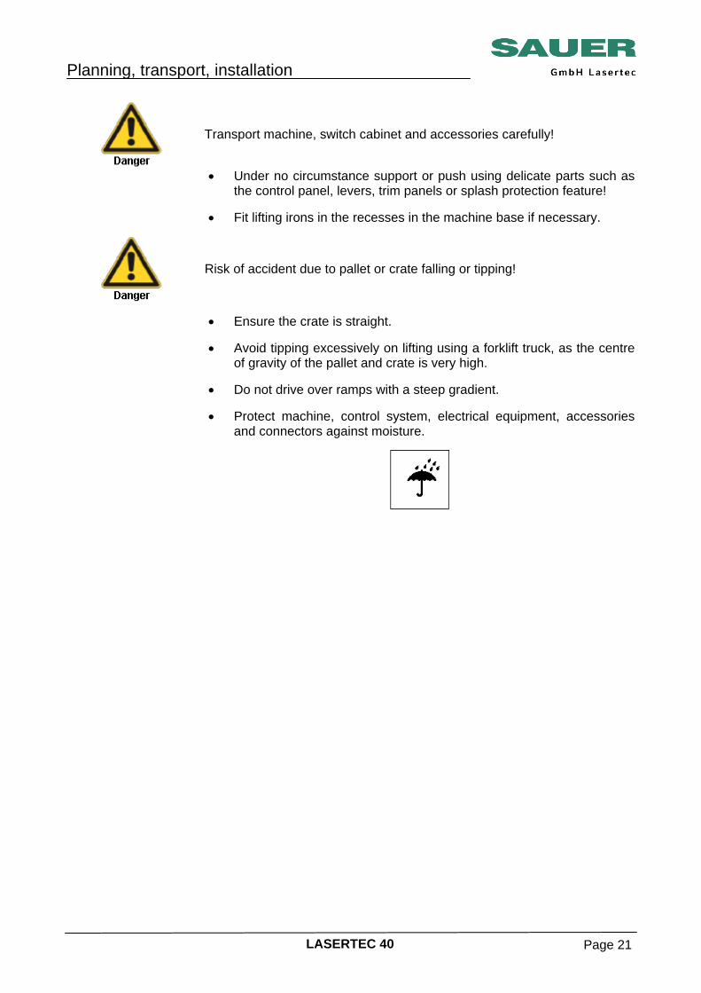
Transport machine, switch cabinet and accessories carefully!
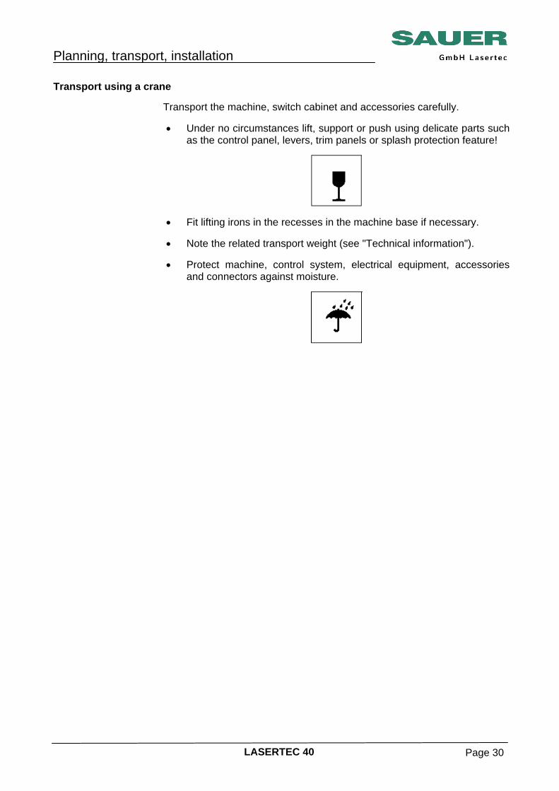
• Under no circumstance support or push using delicate parts such as the control panel, levers, trim panels or splash protection feature!
• Fit lifting irons in the recesses in the machine base if necessary.
Risk of accident due to pallet or crate falling or tipping!
• Ensure the crate is straight.
• Avoid tipping excessively on lifting using a forklift truck, as the centre
of gravity of the pallet and crate is very high. • Do not drive over ramps with a steep gradient.
• Protect machine, control system, electrical equipment, accessories
and connectors against moisture.
Planning, transport, installation
LASERTEC 40 Page 22
What is the purpose of this documentation?
This documentation is aimed at the people responsible for the transportation, positioning and installation of the machine and their staff. They will then be in a position to prepare the installation location and its surroundings so that the machine can be installed and connected immediately on delivery. The data given in these instructions apply to the machine, chip tray, chip conveyor and series transformer. For transport information and installation instructions on other peripheral equipment, see the related information from the manufacturer.
Only the basic installation is performed. The machine is still not ready to operate. All other tasks (alignment, completing the machine, filling with oils and greases and initial commissioning) will be undertaken by authorised commissioning engineers.
Planning, transport, installation
LASERTEC 40 Page 23
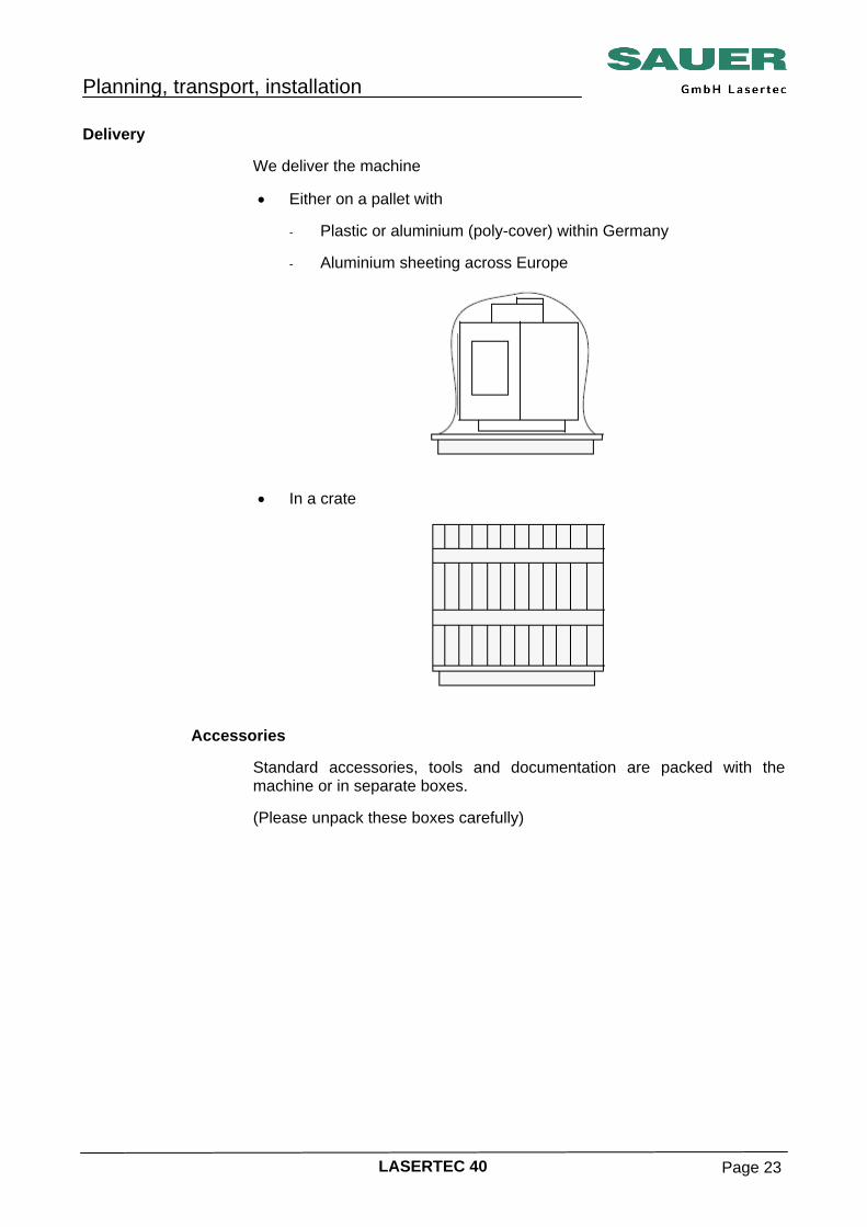
Delivery
We deliver the machine • Either on a pallet with
- Plastic or aluminium (poly-cover) within Germany
- Aluminium sheeting across Europe
• In a crate
Accessories Standard accessories, tools and documentation are packed with the
machine or in separate boxes. (Please unpack these boxes carefully)
Planning, transport, installation
LASERTEC 40 Page 24
Receipt inspection On delivery, immediately check the packaging for transport damage.
Check machine and accessories for transport damage and for completeness, using the delivery note.
In case of damage • Report damage directly to SAUER service and in good time to the
freight haulier. • Contact SAUER and your freight haulier immediately.
• Secure the machine and accessories against further damage!
Planning, transport, installation
LASERTEC 40 Page 25
Transport in the packaging Only transport machine, switch cabinet and accessories to the installation
location in the packaging - if possible.
• It is imperative you observe the markings and instructions on the packaging.
• Take into account the related transport weight and the transport
dimensions (see shipping paperwork and "Technical information").
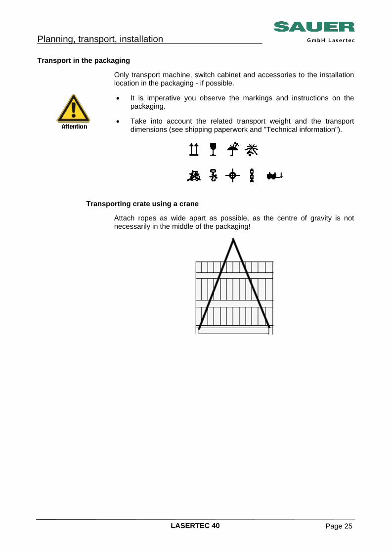
Transporting crate using a crane Attach ropes as wide apart as possible, as the centre of gravity is not
necessarily in the middle of the packaging!
Planning, transport, installation
LASERTEC 40 Page 26
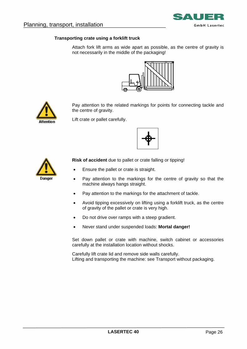
Transporting crate using a forklift truck Attach fork lift arms as wide apart as possible, as the centre of gravity is
not necessarily in the middle of the packaging!
Pay attention to the related markings for points for connecting tackle and the centre of gravity. Lift crate or pallet carefully.
Risk of accident due to pallet or crate falling or tipping! • Ensure the pallet or crate is straight.
• Pay attention to the markings for the centre of gravity so that the
machine always hangs straight. • Pay attention to the markings for the attachment of tackle.
• Avoid tipping excessively on lifting using a forklift truck, as the centre
of gravity of the pallet or crate is very high. • Do not drive over ramps with a steep gradient.
• Never stand under suspended loads: Mortal danger!
Set down pallet or crate with machine, switch cabinet or accessories carefully at the installation location without shocks. Carefully lift crate lid and remove side walls carefully. Lifting and transporting the machine: see Transport without packaging.
Planning, transport, installation
LASERTEC 40 Page 27
Transport equipment required If the tackle, lifting gear and tools stipulated by SAUER are not used,
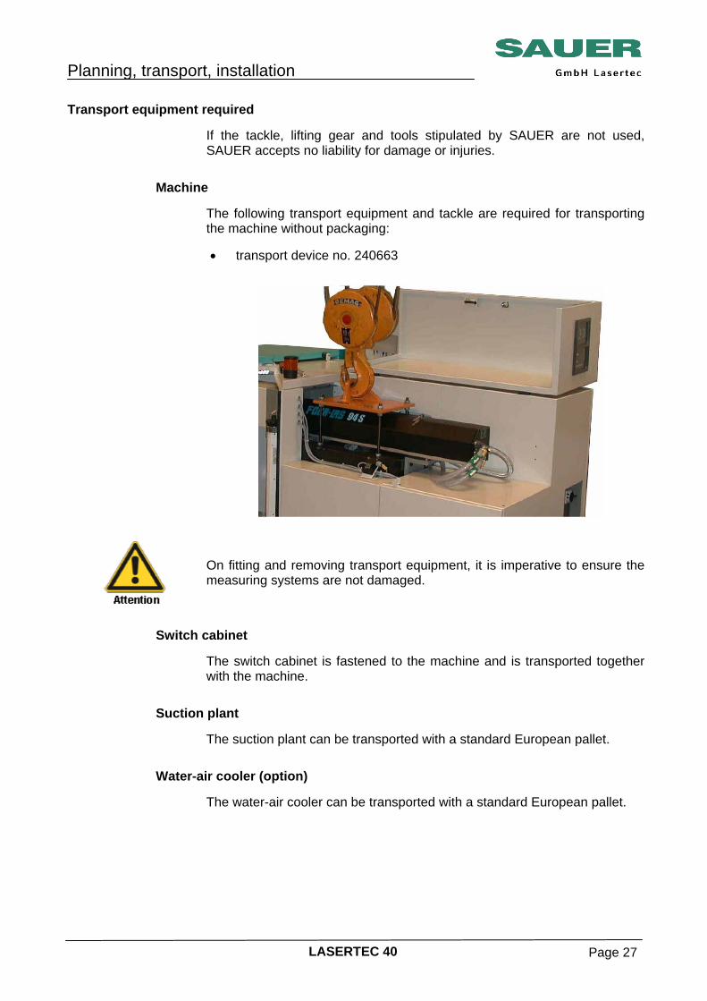
SAUER accepts no liability for damage or injuries. Machine The following transport equipment and tackle are required for transporting
the machine without packaging: • transport device no. 240663
On fitting and removing transport equipment, it is imperative to ensure the measuring systems are not damaged.
Switch cabinet The switch cabinet is fastened to the machine and is transported together
with the machine. Suction plant The suction plant can be transported with a standard European pallet. Water-air cooler (option) The water-air cooler can be transported with a standard European pallet.
Planning, transport, installation
LASERTEC 40 Page 28
Prior to unloading • Check for exterior damages.
- Machine
- Series transformer (option)
- Accessories and peripheral equipment
• Have any damage recorded on the shipping paperwork / delivery note
by the freight haulier. • If possible, take photographs of the damage.
• Inform SAUER service about the damage.
• Remove the fastenings that secure the accessories, peripheral
equipment and the machine to the means of transport (lorry).
Unload the accessories first and then the machine.
Planning, transport, installation
LASERTEC 40 Page 29
Transport data Transport weight Standard ………………………………. Approx. kg ………………. 2 560 Machine with pallet …………….……. Approx. kg ………………. 3 760 Machine with crate ………………….. Approx. kg ………………. 4 210 Exhaust system …………….………... Approx. kg ………………….. 82 Chiller …………………………………. Approx. kg ………………... 185 Transport dimensions, approx. (L x W x H) Machine …………………………………….. ca. m …. 2,30 x 1,40 x 1,95 Exhaust system ……………………………… ca. m …. 0,66 x 0,36 x 1,38 Chiller ………………………………………… ca. m …. 0,85 x 0,55 x 1,02 Transport platform with machine ………….. ca. m …. 2,80 x 1,80 x 2,25 Euro platform with exhausing system …….. ca. m …. 1,20 x 0,80 x 1,60 Euro platform with chiller ……………........... ca. m …. 1,20 x 0,80 x 1,35
Planning, transport, installation
LASERTEC 40 Page 30
Transport using a crane Transport the machine, switch cabinet and accessories carefully.
• Under no circumstances lift, support or push using delicate parts such
as the control panel, levers, trim panels or splash protection feature!
• Fit lifting irons in the recesses in the machine base if necessary.
• Note the related transport weight (see "Technical information").
• Protect machine, control system, electrical equipment, accessories
and connectors against moisture.
Planning, transport, installation
LASERTEC 40 Page 31
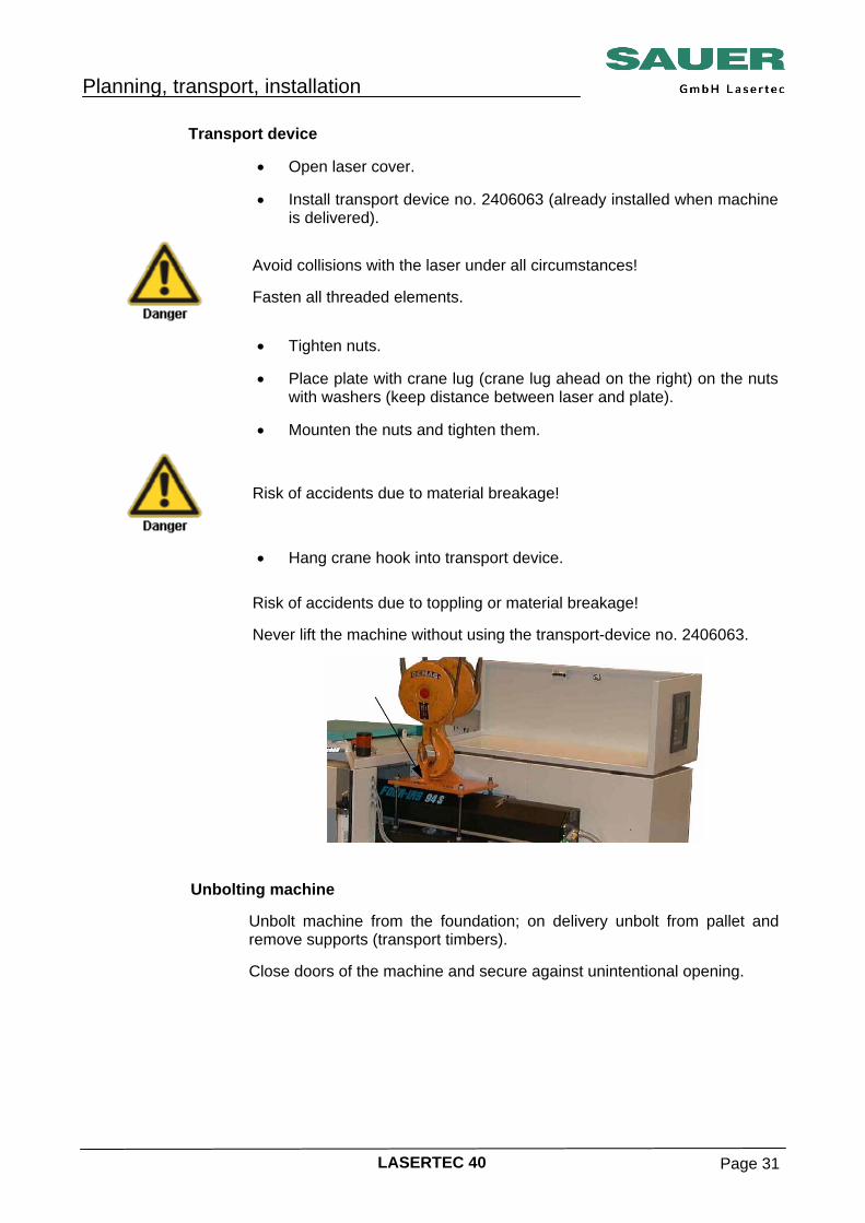
Transport device • Open laser cover.
• Install transport device no. 2406063 (already installed when machine
is delivered).
Avoid collisions with the laser under all circumstances! Fasten all threaded elements.
• Tighten nuts.
• Place plate with crane lug (crane lug ahead on the right) on the nuts
with washers (keep distance between laser and plate). • Mounten the nuts and tighten them.
Risk of accidents due to material breakage!
• Hang crane hook into transport device. Risk of accidents due to toppling or material breakage!
Never lift the machine without using the transport-device no. 2406063.
Unbolting machine Unbolt machine from the foundation; on delivery unbolt from pallet and
remove supports (transport timbers). Close doors of the machine and secure against unintentional opening.
Planning, transport, installation
LASERTEC 40 Page 32
Lifting machine
Check whether all connections have been removed prior to lifting and transporting away. Lift machine carefully and ensure the machine is hanging straight.
Balancing If necessary, set down machine and balance.
Risk of accident due to material fracture! Fully screw in pins and shackles.
Transporting, setting down
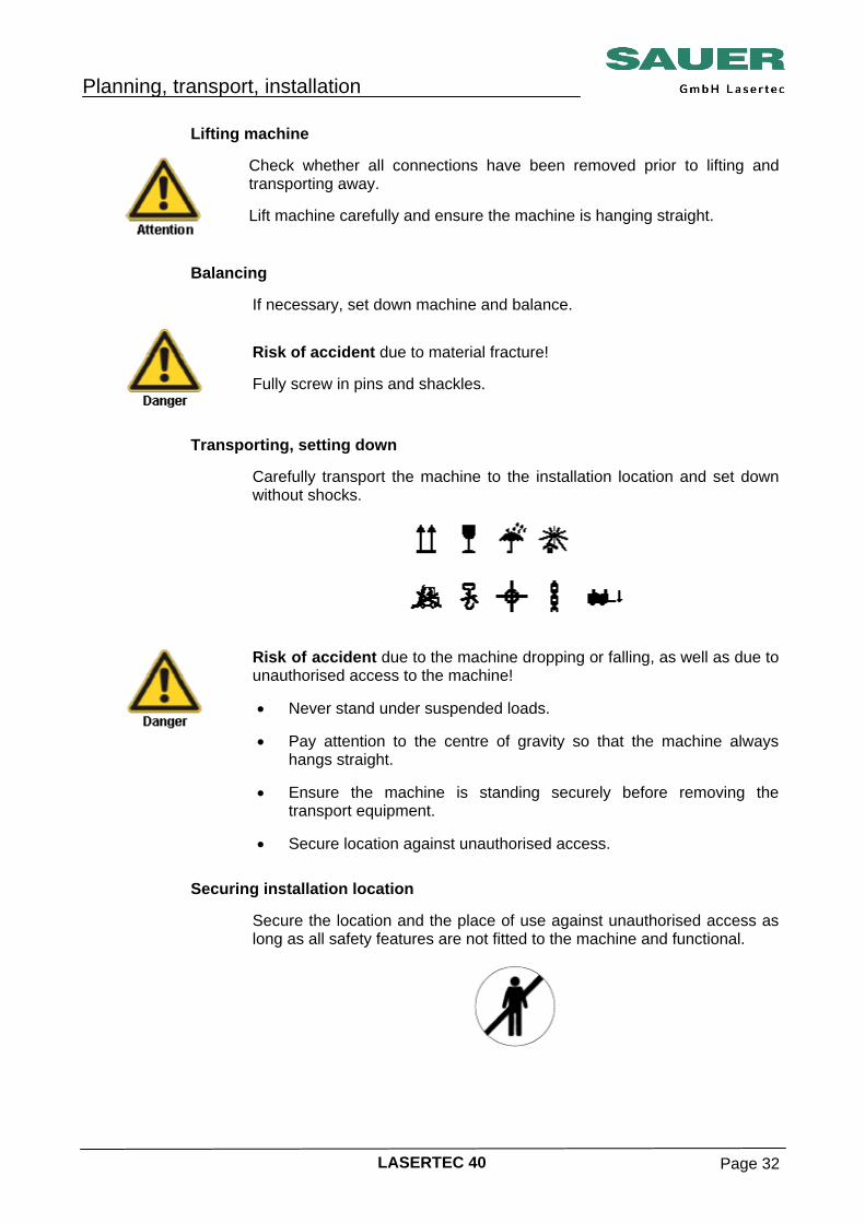
Carefully transport the machine to the installation location and set down without shocks.
Risk of accident due to the machine dropping or falling, as well as due to unauthorised access to the machine! • Never stand under suspended loads.
• Pay attention to the centre of gravity so that the machine always
hangs straight. • Ensure the machine is standing securely before removing the
transport equipment. • Secure location against unauthorised access.
Securing installation location Secure the location and the place of use against unauthorised access as
long as all safety features are not fitted to the machine and functional.
Planning, transport, installation
LASERTEC 40 Page 33
Removing transport equipment
Avoid collisions with the laser under all circumstances.
• Unscrew upper nuts.
• Remove the plate.
• Loosen the bottom lock nut.
• Unscrew the threaded rod.
Re-assemble the machine elements which were removed for the transport.
The transport devices are included in the scope of delivery of the machine and are required whenever the machine has to be moved within the production site. Therefore, the device cannot be taken back by SAUER. After the transport, store the transport device at a safe place.
Planning, transport, installation
LASERTEC 40 Page 34
Transport using roller systems Carriages on rollers or similar roller transport systems are required to
move the machine to a place that is inaccessible for crane.
It is only allowed to use roller transport systems for transport on an even floor. On sloping floors there is a risk of accident due to the machine sliding off or tipping.
In addition to these safety instructions, it is essential you also follow the
safety instructions in the operating instructions for the roller, transport and lifting systems used. • Transport using roller transport systems is only allowed to be
undertaken by authorised specialist personnel. A minimum of 2 people are required for transport. The safe seating of the roller systems is to be continuously checked.
• It is to be ensured the safety distance to people not directly involved
in the transport is 1.5 times the height of the item lifted. • The systems necessary for the transport are only allowed to be used
at fixed points on the machine, i.e. at the machine base.
The transport timbers must be removed prior to transport using the roller systems.
• Secure the machine against slipping prior to and during fitting and
transport using the roller transport systems.
There must not be any lubricating oil or grease between the machine base and the bearing surface on the roller transport system. The surface between the machine base and the roller system must be fitted with non-slip materials!
• In tight spaces (< 2 m), there must not be any people between the
machine and fixed objects (walls, pillars, etc.). • When fitting roller systems, the steering roller is always to be fitted
last and is also to be removed first on the removal of roller systems. • Roller transport systems without any steering must be fitted to the
outermost points under the machine base.
Planning, transport, installation
LASERTEC 40 Page 35
• The machine must not be lifted using the systems necessary for transport higher than absolutely necessary for inserting roller transport systems, i.e. max. height of steel rollers.
• When working with the systems necessary for lifting the machine, the
machine is to be appropriately secured against sudden lowering and sliding.
• Before moving the machine, the individual machine assemblies are to
be moved to the related positions for fitting the transport (most neutral machine centre of gravity).
Planning, transport, installation
LASERTEC 40 Page 36
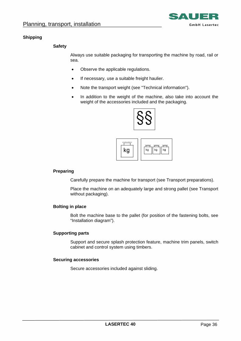
Shipping Safety Always use suitable packaging for transporting the machine by road, rail or
sea. • Observe the applicable regulations.
• If necessary, use a suitable freight haulier.
• Note the transport weight (see "Technical information").
• In addition to the weight of the machine, also take into account the
weight of the accessories included and the packaging.
Preparing Carefully prepare the machine for transport (see Transport preparations).
Place the machine on an adequately large and strong pallet (see Transport without packaging).
Bolting in place Bolt the machine base to the pallet (for position of the fastening bolts, see
“Installation diagram”). Supporting parts Support and secure splash protection feature, machine trim panels, switch
cabinet and control system using timbers. Securing accessories Secure accessories included against sliding.
Planning, transport, installation
LASERTEC 40 Page 37
Attaching moisture protection Protect machine and accessories against moisture using suitable means,
e.g. using moisture absorbing agent, corrosion protection greases, covers, etc.
Marking packaging Attach appropriate information about the centre of gravity, the attachment
of tackle, etc. to the packaging.
Risk of accident due to tipping machine, as the centre of gravity is not necessarily in the middle of the crate.
Attach marking and safety instructions.
Planning, transport, installation
LASERTEC 40 Page 38
Installation General instructions
These installation instructions provide information on the initial and renewed installation, alignment and fastening of your machine. During lifting, moving and installation, also follow the instructions in this section.
Provide the necessary space, connections and tools on-site.
Installation, assembly, connection and commissioning can also be undertaken by our customer service.
Stability Ensure machine and accessories are standing securely.
Follow the building regulations; these define the load bearing structures for the stability of the machine.
Accessibility Pay attention to good accessibility for the operation and maintenance of
the machine as well as for adequate clear areas for movement and sufficient space for the machine operator.
Planning, transport, installation
LASERTEC 40 Page 39
Regulations As a matter of priority, the local regulations, laws and stipulations are to be
followed during the installation of machines and switch cabinets, e.g. in Germany: Health and safety at work act, VDE accident prevention regulations, etc..
Maintain the stipulated safety areas and escape routes:
In accordance with VDE 0100 part 729, e.g., escape routes must have a minimum width of 500 mm, 700 mm for flaps and doors.

Planning, transport, installation
LASERTEC 40 Page 40
Aligning and fastening The machine base has recesses for fastening bolts and for attaching
levelling elements or fixing devices. Preparing permitted installation elements • Position of the fastening points
• Type and number of levelling elements
• Installation dimensions, fastening bolts
Delivery ex-works In case of delivery by SAUER, the installation elements are in a separate
package on the machine's pallet. Providing suitable measuring instruments • Provide spirit level (machine spirit level)
Accuracy (mm/m): 0,02/1
Pay attention to clean bearing surfaces!
Planning, transport, installation
LASERTEC 40 Page 41
Installing machine, alternative 1 • Fasten machine supports (9) using threaded rod (2), conical washer
(plate) (8), spherical washer (7), conical washer (6), spherical washer (5), washer (4) and nut (3) in recess (1) on the machine base.
Follow order stated for the fastening elements!
• Set down machine.
Planning, transport, installation
LASERTEC 40 Page 42
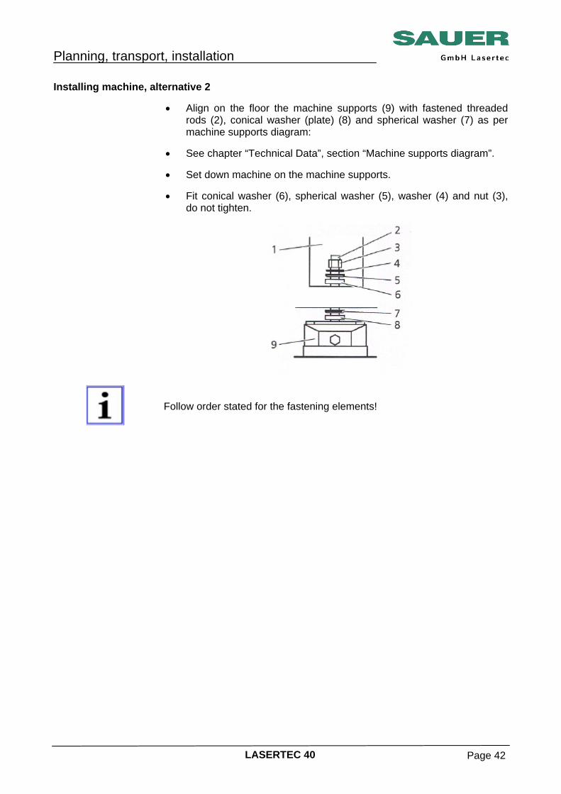
Installing machine, alternative 2 • Align on the floor the machine supports (9) with fastened threaded
rods (2), conical washer (plate) (8) and spherical washer (7) as per machine supports diagram:
• See chapter “Technical Data”, section “Machine supports diagram”.
• Set down machine on the machine supports.
• Fit conical washer (6), spherical washer (5), washer (4) and nut (3),
do not tighten.
Follow order stated for the fastening elements!
Planning, transport, installation
LASERTEC 40 Page 43
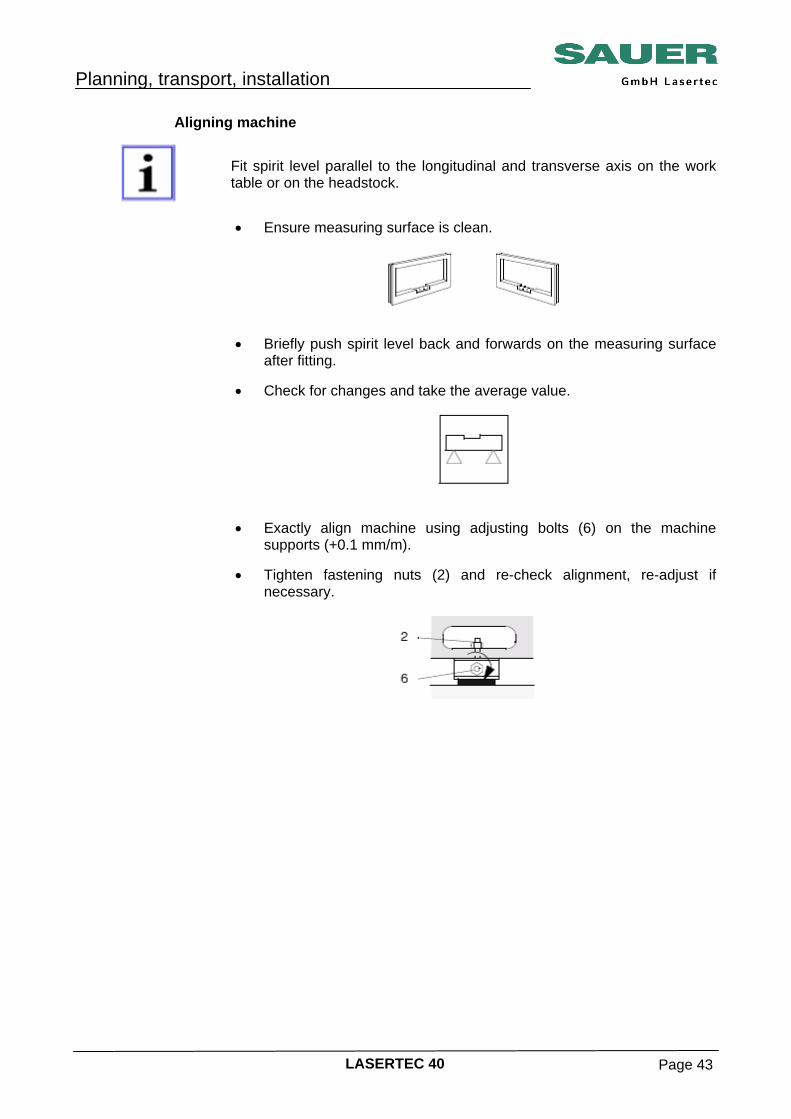
Aligning machine
Fit spirit level parallel to the longitudinal and transverse axis on the work table or on the headstock.
• Ensure measuring surface is clean.
• Briefly push spirit level back and forwards on the measuring surface
after fitting. • Check for changes and take the average value.
• Exactly align machine using adjusting bolts (6) on the machine
supports (+0.1 mm/m). • Tighten fastening nuts (2) and re-check alignment, re-adjust if
necessary.
Planning, transport, installation
LASERTEC 40 Page 44
Connection, assembly
General instructions These assembly instructions contain information on the assembly and
connection of the machine. "As per and in addition to the general installation conditions, VDW 502 A
and LMW 188 A, the operating organisation undertakes the obligation to provide technical support during installation and repair work, in particular the provision of suitable ladders, platforms, scaffolding, heavy tools, lifting gear etc.".
Assembly, connection and commissioning can be undertaken by our
customer service. Provide the necessary connections on site at the installation location: • Electrical power
• Compressed air
• Central supply and disposal facilities
For information on the position of the connection points and connection ratings, see “Technical information”.
Removing transport locks
Ensure the transport locks are removed prior to commissioning!
Planning, transport, installation
LASERTEC 40 Page 45
Removing corrosion protection
Completely remove corrosion protection from bare metal machine parts such as guides, stop surfaces, bolted and clamping surfaces!
Use suitable solvent or cleaning agent. Damage to lacquer by solvents! Do not use aggressive solvents: • No trichloroethyline or similar,
• No acetone or similar
Oiling parts Oil or grease bare metal parts. Use the same oil and grease types as for
the central lubrication system.
Planning, transport, installation
LASERTEC 40 Page 46
Connection cooling plant (Design: Water-air cooler) Installation place Do not install the cooling plant in an area in which other facility plants
cause a high ambient temperature. The cooling plant operates efficiently up to an ambient temperature of 40°C. At higher ambient temperatures the cooling plant does not provide the required cooling capacity, since the cooling agent cannot be cooled sufficiently. A pressure switch protects the coolant circuit against increased coolant pressure. The diode on the front plate will light up. The cooling plant must be installed in such manner to provide a sufficient air circulation. Make sure that the air input and output openings of the control cubicle are completely free even for a later operation. A restricted airflow impedes the designed cooling capacity.
Positioning The free-standing cooling plant must be placed on a horizontal surface.
Install the plant at a minimum distance of 30 cm from other objects in order to provide an unrestricted airflow through the cooling plant. The air outlet on the rear side of the plant must be free for 80 cm. Take preventive measures that the blown off air on the rear side is not redirected back to the suction.
Connect water hoses Before commissioning the cooling plant the first time together with the
consumer device, connect the water hoses. Ensure that all lines are designed for the maximum operating pressure of the cooling plants. The water connections are found on the rear side of the cooling plant. Make sure that no cross loads occur on the connecting spots. If required, install a sufficient tension relief.
While connecting the water hoses, observe the flow direction of the water: Blue sign = water feeding line of cooling plant (OUT) Red sign = water return of cooling plant (IN)
Planning, transport, installation
LASERTEC 40 Page 47
1 Water feeder line (to laser) BLUE 2 Water return line (from laser) RED
• Install cooling water inlet and outlet below the service door and
connect to the water-air cooler.
1 Power switch 2 Serial data cable 3 Water feeder (to laser) BLUE 4 Water return line (from laser) RED 5 Voltage supply 3x 400V 50/60 Hz
Planning, transport, installation
LASERTEC 40 Page 48
Electrical connections Connection of voltage supply The connection to the electrical supply is installed on the rear side by
means of cable. Connect the plant by external disconnector with sufficient contact opening next to the plant which is marked as part of the plant. Besides secure the phase with a 16A fuse. When using a 3 pole safety automat (characteristic C), the latter may also be used as disconnector at the same time, if the aforesaid requirements are met. The fuses must be designed for inductive load!
1 Power switch 2 Signal connection (9pin SUBD) 3 Voltage supply
Planning, transport, installation
LASERTEC 40 Page 49
Connection for data exchange (SUB-D plug) The plug SUB-D 9 pol. for data monitoring is located at the rear side of the
cooling plant.
Plug allocation Signal exit Pin 1 Alarm Temperature Alarm Pin 2 Alarm Flow Pin 3 Remote start Pin 4 +24V Pin 5 GND Pin 6 Collective failure message Pin 7 Collective failure message Pin 8 Water level alarm Pin 9 NC Commissioning of Cooling Plant • Switch on the power switch. The indication of the cooling control
shows ”OFF”. • Press the ”Standby” key. The display indicates the actual temperature
and failure messages. • Water level and water alarm are pending.
• Now refill water through the filling opening on the front side of the
cooler. The light diode Water level warning (yellow) fades first. Refill water until also the light diode Water level alarm disappears.
• The cooler is ready for operation and starts cooling.
• Filling capacity approx. 30 l.
For start-up must be preparated a minimum 30 l de-ionized water with the conductivity of < 2,5 µS.
Planning, transport, installation
LASERTEC 40 Page 50
Prepare cooling plant for transportation As far as the cooling plant consists of a multitude of sensitive electronic
and mechanical components, observe the following preconditions and instructions for storage, installation and transportation of the plant.
Transportation The transportation of the cooling plan must be performed as careful and
shock-free and vibration-free as possible. Please observe the following measures: • The cooling plant must be completely emptied before transportation.
• Use only suitable packing material - shock-resistant and highly
vibration-absorbent to ensure a safe transportation of the sensitive components.
• Furthermore, the packing must provide a protection of the cooling
plant from dust and soiling. • Pack the cooling plant in such manner to prevent it from shocks and
falling. • If the cooling plant is shipped separately, use the original packing
bolster. • Required marking of the transported goods includes ”Protect against
humidity”, ”Transport and store in vertical position” and ”Fragile”.
Danger of freezing! Before the transportation the cooling plant must be completely emptied, otherwise danger of damage by freezing cooling water.
Storage • Always empty the cooling plant before storage.
• The cooling plant must be stored horizontally only.
• Ensure protection against dust and moisture.
• For storage, the following ambient conditions must be observed:
Temperature: 5 °C to + 65 °C Relative air humidity: 10 – 80 %, Not condensing
Planning, transport, installation
LASERTEC 40 Page 51
Connection of Cooling Plant (Special option: Water-water cooler) Guide fresh water inlet and outlet from underneath into the control cubicle
and connect it to the planned places. See also ”Operating manual laser system”.
Planning, transport, installation
LASERTEC 40 Page 52
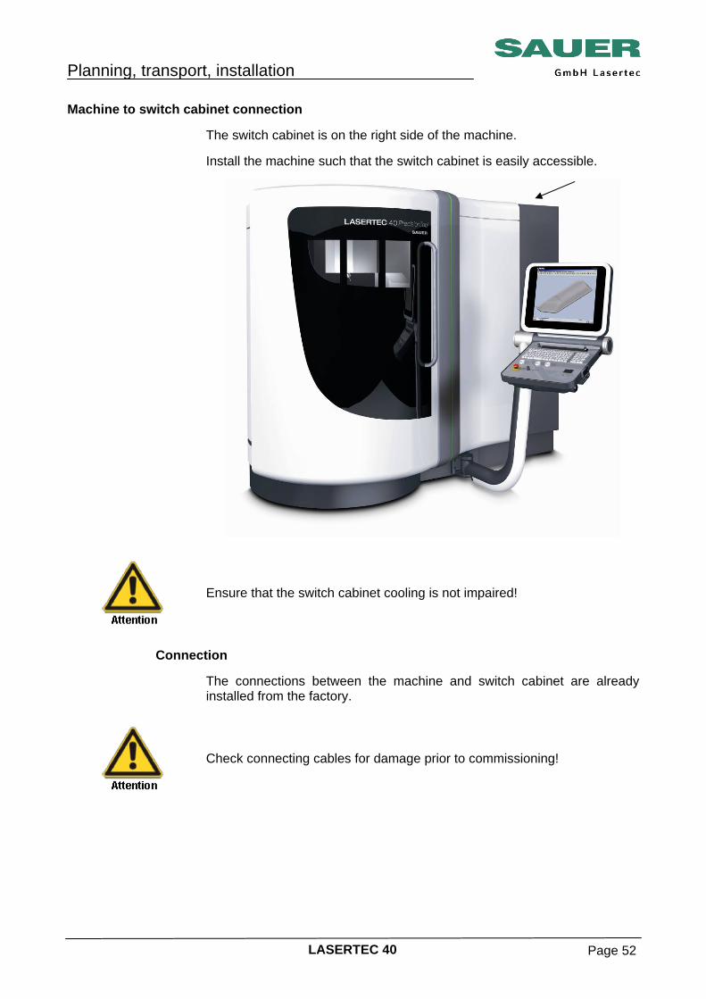
Machine to switch cabinet connection The switch cabinet is on the right side of the machine.
Install the machine such that the switch cabinet is easily accessible.
Ensure that the switch cabinet cooling is not impaired!
Connection The connections between the machine and switch cabinet are already
installed from the factory.
Check connecting cables for damage prior to commissioning!
Planning, transport, installation
LASERTEC 40 Page 53
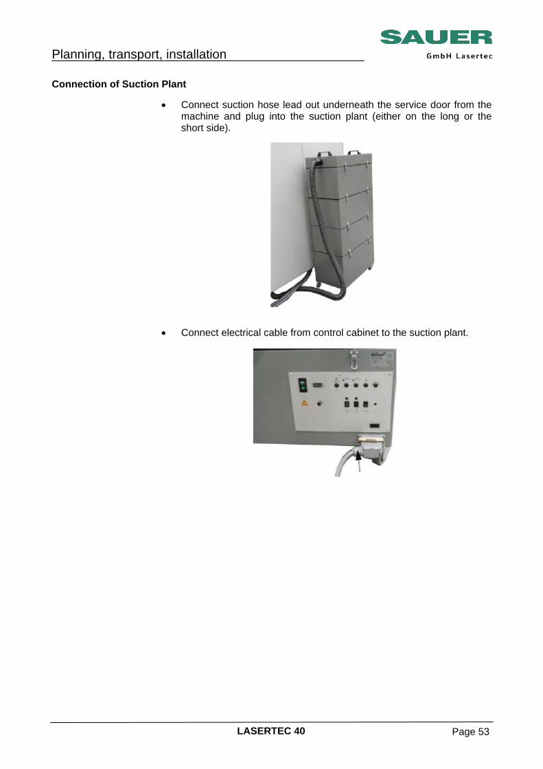
Connection of Suction Plant • Connect suction hose lead out underneath the service door from the
machine and plug into the suction plant (either on the long or the short side).
• Connect electrical cable from control cabinet to the suction plant.
Planning, transport, installation
LASERTEC 40 Page 54
Electrical connection
Risk of accident due electrical power! • The electrical connection is only allowed to be made by an electrician.
• The locally applicable regulations and directives are to be observed
as a matter of priority.
During work on electrical equipment, electronic components may be damaged by incorrect or faulty connection. It is imperative the information in the circuit diagrams is followed!
Supply cable, fuse protection The supply and fuse protection are to be designed as per the information
on the rating plate for the switch cabinet.
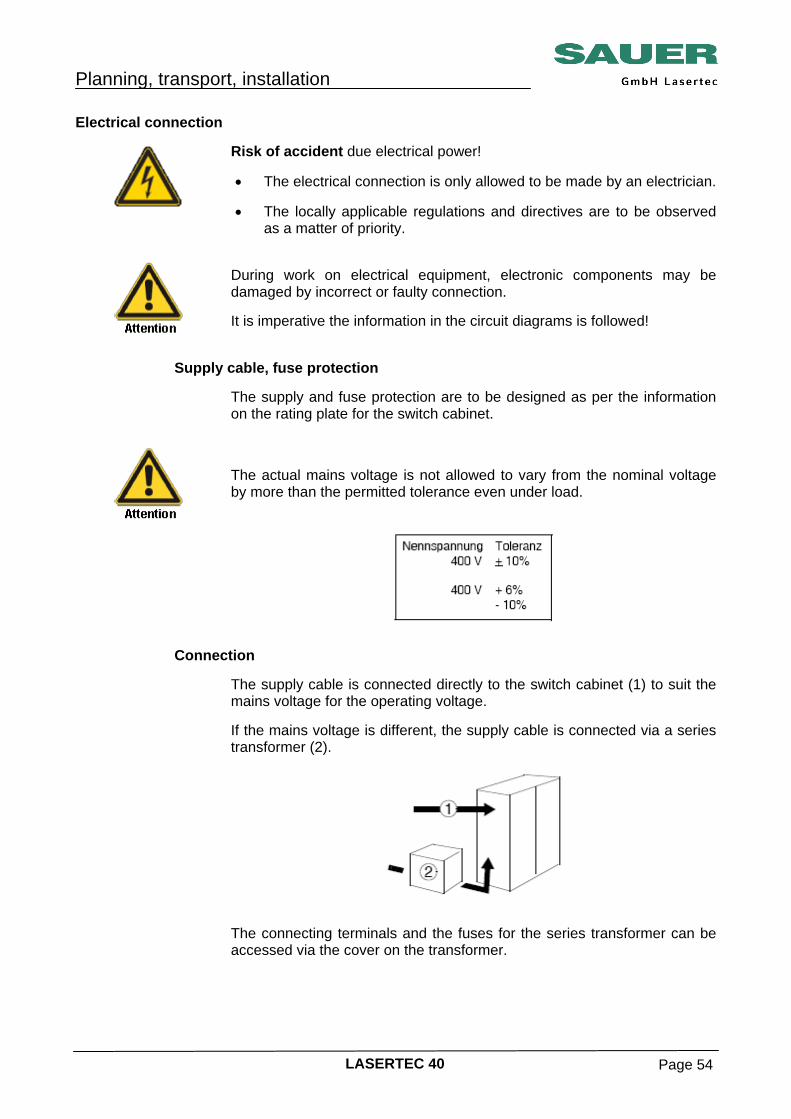
The actual mains voltage is not allowed to vary from the nominal voltage by more than the permitted tolerance even under load.
Connection The supply cable is connected directly to the switch cabinet (1) to suit the
mains voltage for the operating voltage. If the mains voltage is different, the supply cable is connected via a series transformer (2).
The connecting terminals and the fuses for the series transformer can be
accessed via the cover on the transformer.
Planning, transport, installation
LASERTEC 40 Page 55
Connecting Switch off supply cable (power supply) and secure against switching back
on or remove fuse for the supply cable and attach appropriate label.
Mortal danger due to high electrical voltage! It is imperative you check the supply cable is isolated.
Switch cabinet
• Master switch ”OFF”.
• Lay the supply cable or connecting cable from the series transformer though the cable gland and strain relief on the switch cabinet.
PG cable glands are not included in the items supplied.
Connect earth conductor PE to green-yellow terminal and supply cable L1, L2 and L3 to terminal strip X1.
Do not connect neutral conductor yet.
• Check voltage on the supply cable L1, L2, and L3 to the neutral
conductor on the customer's mains supply.
• Connect neutral conductor N to the brown terminal on terminal strip X1.
• Pay attention to markings in the switch cabinet.

Planning, transport, installation
LASERTEC 40 Page 56
Series transformer In case of connection using a series transformer, remove the cover from
the transformer.
• Undo ring bolts and fastening bolts on the cover and lift off cover.
Do not damage earth conductor. Guide the supply cable through the cable gland and strain relief on the series transformer.
Connect earth conductor PE to green-yellow terminal and supply cable L1, L2 and L3 to terminal strip X1.
Do not connect neutral conductor yet.
• Check voltage on the supply cable L1, L2, and L3 to the neutral conductor on the customer's mains supply.
• Connect neutral conductor N to brown terminal on terminal strip X1.
• Check connection, close cover again and bolt in place.
• Pay attention to secure connection of the earth wire to the cover.
Suction plant
Guide angular plug (10 poles) from the control cu-bicle bottom and plug it into the suction plant, se-cure with clip (see ”Connection of suction plant”).
Planning, transport, installation
LASERTEC 40 Page 57
Cooling plant (for the design water-air cooler only)
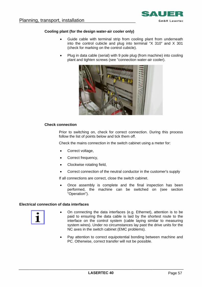
• Guide cable with terminal strip from cooling plant from underneath into the control cubicle and plug into terminal ”X 310” and X 301 (check for marking on the control cubicle).
• Plug in data cable (serial) with 9 pole plug (from machine) into cooling
plant and tighten screws (see ”connection water-air cooler).
Check connection
Prior to switching on, check for correct connection. During this process follow the list of points below and tick them off.
Check the mains connection in the switch cabinet using a meter for: • Correct voltage,
• Correct frequency,
• Clockwise rotating field,
• Correct connection of the neutral conductor in the customer's supply
If all connections are correct, close the switch cabinet.
• Once assembly is complete and the final inspection has been performed, the machine can be switched on (see section "Operation").
Electrical connection of data interfaces
• On connecting the data interfaces (e.g. Ethernet), attention is to be paid to ensuring the data cable is laid by the shortest route to the interface on the control system (cable laying similar to measuring system wires). Under no circumstances lay past the drive units for the NC axes in the switch cabinet (EMC problems).
• Pay attention to correct equipotential bonding between machine and
PC. Otherwise, correct transfer will not be possible.
Planning, transport, installation
LASERTEC 40 Page 58
Fluid connection for the CO2-jet cleaning system option
Compressed air Fluid condition:
• oil-free • dry, pressure dew point -40°C or better
• Pressure range 6 – 16 bar
• Typical operating pressure and consumption: 15 bar and 550 l/min
(approx. 35m³/h) • Connection to standard compressed air supply (NW 7,2)
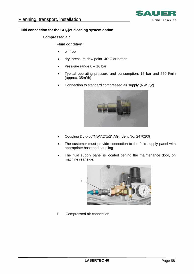
• Coupling DL-plug*NW7,2*1/2" AG, Ident.No. 2470209 • The customer must provide connection to the fluid supply panel with
appropriate hose and coupling. • The fluid supply panel is located behind the maintenance door, on
machine rear side.
1 Compressed air connection
Planning, transport, installation
LASERTEC 40 Page 59
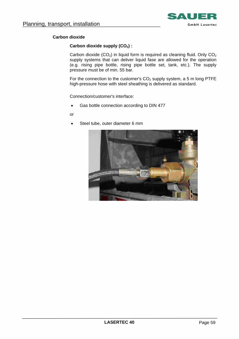
Carbon dioxide Carbon dioxide supply (CO2) :
Carbon dioxide (CO2) in liquid form is required as cleaning fluid. Only CO2 supply systems that can deliver liquid fase are allowed for the operation (e.g. rising pipe bottle, rising pipe bottle set, tank, etc.). The supply pressure must be of min. 55 bar. For the connection to the customer's CO2 supply system, a 5 m long PTFE high-pressure hose with steel sheathing is delivered as standard. Connection/customer's interface: • Gas bottle connection according to DIN 477
or • Steel tube, outer diameter 6 mm
Planning, transport, installation
LASERTEC 40 Page 60
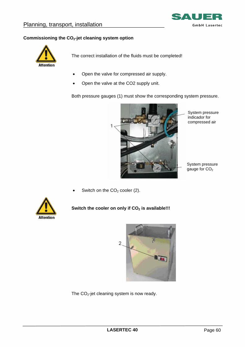
Commissioning the CO2-jet cleaning system option
The correct installation of the fluids must be completed!
• Open the valve for compressed air supply.
• Open the valve at the CO2 supply unit.
Both pressure gauges (1) must show the corresponding system pressure.
• Switch on the CO2 cooler (2).
Switch the cooler on only if CO2 is available!!!
The CO2-jet cleaning system is now ready.
System pressure indicador for compressed air
System pressure gauge for CO2
Planning, transport, installation
LASERTEC 40 Page 61
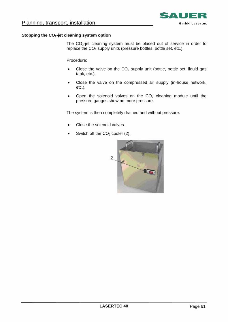
Stopping the CO2-jet cleaning system option The CO2-jet cleaning system must be placed out of service in order to
replace the CO2 supply units (pressure bottles, bottle set, etc.). Procedure: • Close the valve on the CO2 supply unit (bottle, bottle set, liquid gas
tank, etc.). • Close the valve on the compressed air supply (in-house network,
etc.). • Open the solenoid valves on the CO2 cleaning module until the
pressure gauges show no more pressure. The system is then completely drained and without pressure. • Close the solenoid valves.
• Switch off the CO2 cooler (2).
Planning, transport, installation
LASERTEC 40 Page 62
Checklist for electrical connection
Mains voltage is sufficiently stable at the stipulated reactive power and does not vary from the rated voltage by more than the tolerance allowed.
Correct mains voltage is available or appropriate voltage converter series transformer is available.
Supply cable and fuse protection are designed in accordance with the power consumption and the applicable regulations.
Supply cable is laid in accordance with the applicable regulations and protected against damage.
Supply cable (connecting cable) and earth conductor are correctly connected in accordance with regulations to series transformer and terminal strip X1 in the switch cabinet.
All connectors and connecting cables are inserted and secured.
Cable glands and strain relief are fitted.
All electrical cables are secured against damage, e.g. by chaffing, kinking, crushing, tearing, etc, including on movement by the axis slides.
Correct voltage, frequency and clockwise rotating field are present at terminal strip X1 in the switch cabinet.
Direction of rotation of coolant pump, fans, etc. is as per the arrow on the related housing.
Correct connection of the neutral conductor in the customer's supply.
Planning, transport, installation
LASERTEC 40 Page 63
Final inspection It is imperative a final inspection is performed after the assembly of the
machine. During this process follow the list of points and tick them off. • Check levels of all lubricants and top up as necessary. You will find
the necessary information in Initial commissioning (see “Maintenance”).
• Have all transport locks been removed?
• Have all trim panels and safety features been fitted and are they fully
functional? Checklist for final inspection
Load bearing capacity of the floor is adequate.
Necessary safety distances and working areas are met as per applicable regulations.
Machine is stable and positioned and installed as per the applicable regulations.
Electrical connection is fully checked and also all points in the check list for the electrical connection have been taken into account and ticked off.
Gas connection completely checked.
All transport locks and transport equipment as well as all assembly aids and tools have been removed.
All splash protection features and trim panels as well as splash protection features are fitted.
All monitoring switches and safety switches are fully functional.
Levels in the central lubrication system and the hydraulic unit are adequate.
All lines are free of leaks and secured against damage, e.g. by chaffing, kinking, crushing, tearing, etc, including on movement by the axis slides.
Planning, transport, installation
LASERTEC 40 Page 64
Splash protection feature are free of leaks.
Clamping, fastening and connecting bolts are tightened.
Documentation (safety instructions, machine manuals, control system manuals, circuit diagrams, etc.) is available.
Documentation (safety instructions, machine, control system manuals) worked through.
Planning, transport, installation
LASERTEC 40 Page 65
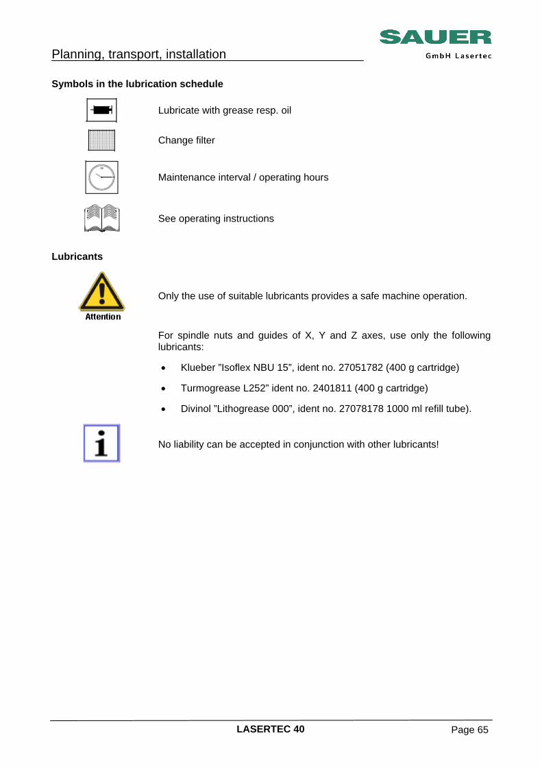
Symbols in the lubrication schedule
Lubricate with grease resp. oil
Change filter
Maintenance interval / operating hours
See operating instructions
Lubricants
Only the use of suitable lubricants provides a safe machine operation.
For spindle nuts and guides of X, Y and Z axes, use only the following
lubricants: • Klueber ”Isoflex NBU 15”, ident no. 27051782 (400 g cartridge)
• Turmogrease L252” ident no. 2401811 (400 g cartridge)
• Divinol ”Lithogrease 000”, ident no. 27078178 1000 ml refill tube).
No liability can be accepted in conjunction with other lubricants!
Planning, transport, installation
LASERTEC 40 Page 66
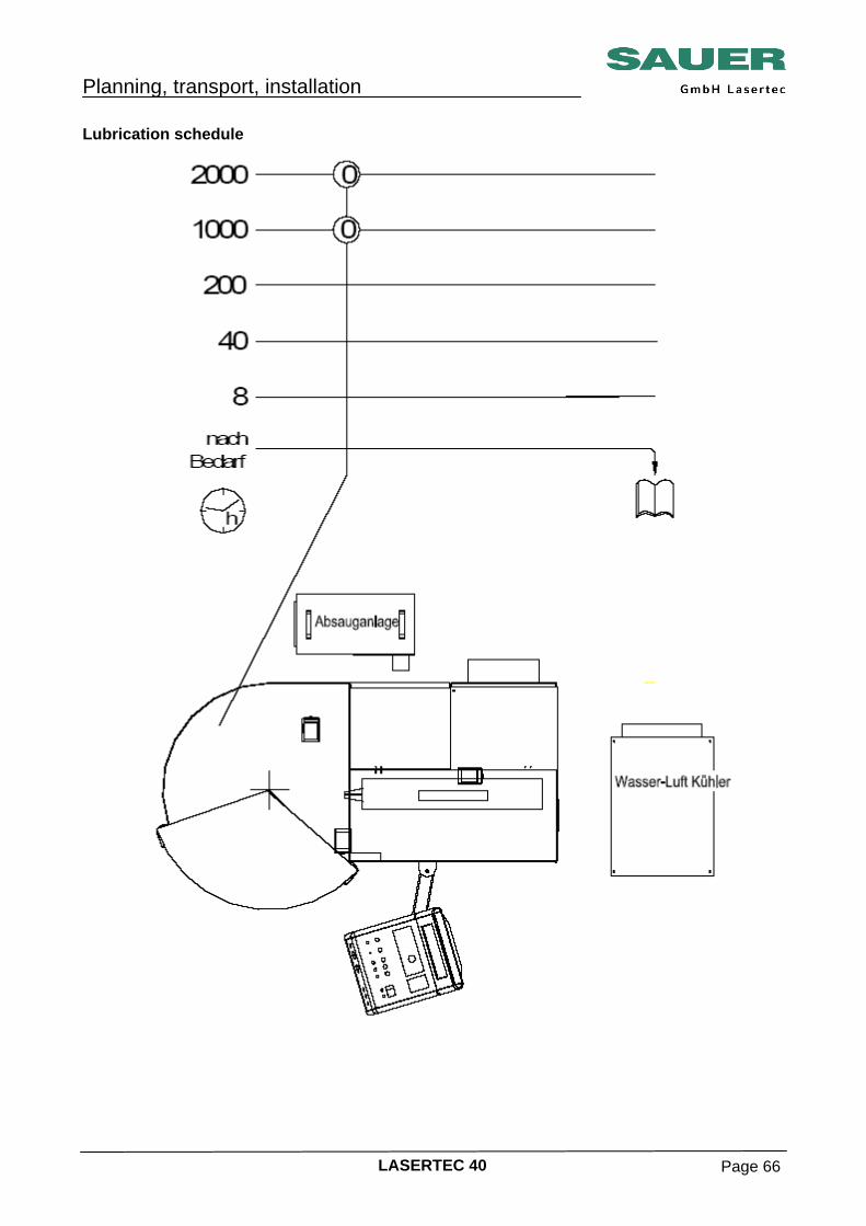
Lubrication schedule
Planning, transport, installation
LASERTEC 40 Page 67
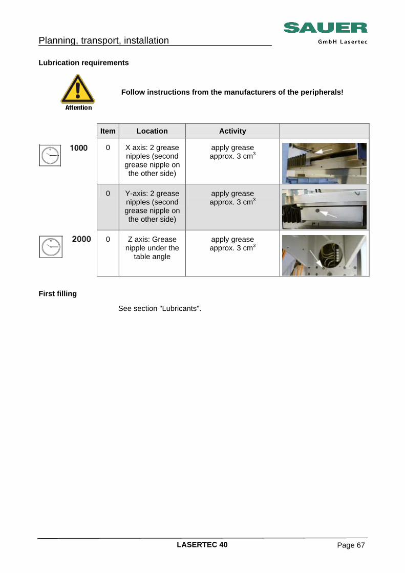
Lubrication requirements
Follow instructions from the manufacturers of the peripherals!
Item Location Activity
0 X axis: 2 grease nipples (second grease nipple on the other side)
apply grease approx. 3 cm3
0 Y-axis: 2 grease nipples (second grease nipple on the other side)
apply grease approx. 3 cm3
0 Z axis: Grease nipple under the
table angle
apply grease approx. 3 cm3
First filling
See section "Lubricants".
Planning, transport, installation
LASERTEC 40 Page 68
Lubricant selection table Issue: 06/2004 Reliable operation of the machine will only be ensured if the correct
lubricants are used. Lubricant approval Minimum requirements for following lubricating and hydraulic oils: DIN standard
Lubricating oil CL 46 in accordance with DIN 51 517, part 2
Lubricating oil CLP 46 in accordance with DIN 51 517, part 3
Lubricating oil CLP 68 in accordance with DIN 51 517, part 3
Hydraulic oil HLP 10 in accordance with DIN 51 524, part 2
Hydraulic oil HLP 22 in accordance with DIN 51 524, part 2
Hydraulic oil HLP 46 in accordance with DIN 51 524, part 2
Hydraulic oil HLP 68 in accordance with DIN 51 524, part 2
Hydraulic oil HLP-D 68 in accordance with DIN 51 524, part 2 If water in the hydraulic oil cannot be excluded, so-called “HLP-D oils” may
be advantageous. These oils must meet the minimum requirements in DIN 51 524, part 2 for hydraulic oil HLP 46 with the exception of the demulsifying characteristics and also have detergent properties.
Lubricating grease KP 2 K-20 in accordance with DIN 51 825 ISO standard
Gearbox oil L-CKC 46 in accordance with ISO 12925-1
Hydraulic oil L-HM 10 in accordance with ISO 11158
Hydraulic oil L-HM 22 in accordance with ISO 11158
Hydraulic oil L-HM 46 in accordance with ISO 11158
Hydraulic oil L-HM 68 in accordance with ISO 11158
Hydraulic oil HLP-D
Lubricating grease KP 2 K-20 does not currently meet any ISO requirements standard
The following products have been mentioned to us by the mineral oil
supplier and are available internationally or in Europe. This list will be continuously updated. Request the current list.
No liability can be accepted in relation to other lubricants!
Planning, transport, installation
LASERTEC 40 Page 69
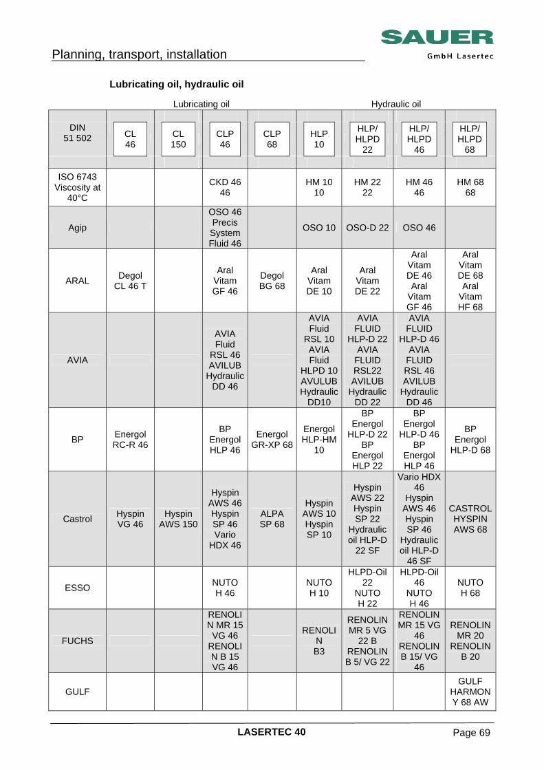
Lubricating oil, hydraulic oil Lubricating oil Hydraulic oil
DIN 51 502
CL 46 CL
150 CLP 46
CLP 68
HLP 10
HLP/ HLPD
22
HLP/ HLPD
46
HLP/ HLPD
68
ISO 6743
Viscosity at 40°C
CKD 46 46 HM 10
10 HM 22
22 HM 46
46 HM 68
68
Agip
OSO 46 Precis System Fluid 46
OSO 10 OSO-D 22 OSO 46
ARAL Degol CL 46 T
Aral Vitam GF 46
Degol BG 68
Aral Vitam DE 10
Aral Vitam DE 22
Aral Vitam DE 46 Aral
Vitam GF 46
Aral Vitam DE 68 Aral
Vitam HF 68
AVIA
AVIA Fluid
RSL 46 AVILUB
Hydraulic DD 46
AVIA Fluid
RSL 10 AVIA Fluid
HLPD 10AVULUBHydraulic
DD10
AVIA FLUID
HLP-D 22 AVIA
FLUID RSL22 AVILUB
Hydraulic DD 22
AVIA FLUID
HLP-D 46 AVIA
FLUID RSL 46 AVILUB
Hydraulic DD 46
BP Energol RC-R 46
BP Energol HLP 46
Energol GR-XP 68
Energol HLP-HM
10
BP Energol
HLP-D 22 BP
Energol HLP 22
BP Energol
HLP-D 46 BP
Energol HLP 46
BP Energol
HLP-D 68
Castrol Hyspin VG 46
Hyspin AWS 150
Hyspin AWS 46 Hyspin SP 46 Vario
HDX 46
ALPA SP 68
Hyspin AWS 10 Hyspin SP 10
Hyspin AWS 22 Hyspin SP 22
Hydraulic oil HLP-D
22 SF
Vario HDX 46
Hyspin AWS 46 Hyspin SP 46
Hydraulic oil HLP-D
46 SF
CASTROL HYSPIN AWS 68
ESSO NUTO H 46 NUTO
H 10
HLPD-Oil 22
NUTO H 22
HLPD-Oil 46
NUTO H 46
NUTO H 68
FUCHS
RENOLIN MR 15
VG 46 RENOLIN B 15 VG 46
RENOLI
N B3
RENOLIN MR 5 VG
22 B RENOLIN B 5/ VG 22
RENOLIN MR 15 VG
46 RENOLIN B 15/ VG
46
RENOLIN MR 20
RENOLIN B 20
GULF GULF
HARMONY 68 AW

Planning, transport, installation
LASERTEC 40 Page 70
Lubricating oil Hydraulic oil
DIN 51 502
CL 46 CL
150 CLP 46
CLP 68
HLP 10
HLP/ HLPD
22
HLP/ HLPD
46
HLP/ HLPD
68
ISO 6743
Viscosity at 40°C
CKD 46 46 HM 10
10 HM 22
22 HM 46
46 HM 68
68
Klüber Klüberoil
GEM 1-46
MOTOREX LAMORA HLP 46
COREX HLP-D 68
RHENUS HydranorHLP 10
Hydranor HLP 22
Hydranor HLP-D 22
Hydranor HLP 46
Hydranor HLP-D 46
Shell Morlina 150
Tellus Oel 46 Tellus Öl
10
Hydrol DO 22
Tellus Oel 22
Hydrol DO 46
Tellus Oel 46
Shellus Tellus OIL 68
Zeller & Gmelin
Divinol ICL ISO
46 Divinol
DHG ISO 46
Divinol
HLP ISO10
Divinol HLP ISO
22 Divinol
DHG ISO 22
Divinol HLP ISO
46 Divinol
DHG ISO 46

Planning, transport, installation
LASERTEC 40 Page 71
Lubricating grease, liquid grease
DIN 51 502 Lubricating grease
Liquid grease
ISO 6743 viscosity
at 40°C
AVIA AVIA LITHOPLEX 2 EP AVIALITH 2 EP
BP
Castrol Spheerol AP 2 Spheerol EPL 2
ESSO Nebula EP 2 Beacon EP 2
FUCHS RENOLIT S2
Klüber CENTOPLEX 2
RHENUS Norlith MZP 2 Norplex LKR 2
Shell Alvania EP grease 2
Zeller & Gmelin Divinol grease EP 2 Divinol Lithogrease 000
Coolant Supplier Description
BASF Glysantin G 48 - Protect Plus
• Central lubrication system initially filled with liquid grease Divinol Lithogrease 000.
• It is only allowed to use and mix with suitable, comparable greases
with the same basis. • Ensure that soiling is prevented each time the system is filled.
(Recommendation: re-fill tube Divinol Lithogrease 000, id.no. 27.078178).