Embed Size (px)
Citation preview
P/N 60221
2003 - 2006 GM VORTEC THROTTLE BY WIRE FUEL
INJECTION 4.8L, 5.3L & 6.0L
WIRE HARNESS INSTALLATION
INSTRUCTIONS
Manual P/N 90570
FIRST EDITION September 2009
Copyright © SEPTEMBER 2009
PAINLESS PERFORMANCE PRODUCTS
2501 Ludelle Street Fort Worth, Texas 76105 (800) 423-969
TABLE OF CONTENTS
Introduction……………………………………………………………………………. 3
ECM Programming…………………………………………………………………..... 3
Tools Needed………………………………………………………………………........ 4
Content of the 60221………………………………………………………………..…. 4
Pre-Installation & Harness Routing Guidelines…………………………………....... 5
Grounding the Vehicle……………………………………………………………….... 6
Installation Instructions…………………………………………………………….… 6
DLC, Cruise Control, Ignition, Fuel Test, Tach…………………………………..… 8
VSS Output, Brake Switch…………………………………………………...………. 9
A/C Request…………………………………………………………………………… 10
Engine Connections………………………………………………………………..….. 10
Knock…………………………………………………………………………………… 10
CKP, Starter B+, Starter Sol., Ground, CMP……………………………………….. 11
MAP, Coils……………………………………………………………………………… 12
ECT, ALT, MAF-IAT………………………………………………………………… 13
Throttle Body, Injectors, Cooling Fan(s)……………………………………………. 14
Tail/Transmission Group…………………………………………………………….. 15
O2 Sensors, Back-Up, Start Switch, Fuel Pump, Fuel Composition Sensor……….. 15
Trans Function………………………………………………………………………… 16
Park/Neutral position, Output Speed Sensor……………………………………….. 16
Input Speed Sensor, Trans, 4L60E to 4L80E……………………………………….. 17
Conclusion…………………………………………………………………………….. 18
Retrieving Trouble Codes……………………………………………………………. 19
FIGURES Figure 1 Content of the 60221 Kit …………………………………………………… 4
Figure 2 Accelerator Pedal …………………………………………………………… 7
Figure 3 TAC Module Connections ………….……………………………………….. 7
Figure 4 Data Link Connector …………….…………………………………….. 8
Figure 5 Cruise Control …………………………………………………………… 8
Figure 6 Brake Switch …………………………………………………………… 8
Figure 7 Brake Switch Relay …………………………………………………………… 9
Figure 8 Knock Sensor …………………………………………………………… 10
Figure 9 Crankshaft Position Sensor …………………………………………………… 11
Figure 10 Camshaft Position Sensor …………………………………………………… 12
Figure 11 Map Sensor …………….……………………………………………… 12
Figure 12 Diver Side Coils ……………………………………………………………. 12
Figure 13 Pass. Side Coils ……….…………….……………………………………... 12
Figure 14 ECT Sensor ……………………………………………………………. 13
Figure 15 Alternator ……………………………………………………………………. 13
Figure 16 MAF-IAT Sensor …………….……………………………………………… 13
Figure 17 Injectors 1, 3, 5, 7 …………….……………………………………………… 14
Figure 18 Injectors 2, 4, 6, 8 …………….……………………………………………… 14
Figure 19 Park/Neutral Position ……………………………………………………. 16
Figure 20 VSS Sensor …………….……………………………………………… 17
Figure 21 4L80E Connection s ……………………………………………………. 17
Figure 22 4L60E Trans Connection …………….……………………………………… 17
Figure 23 Transmission Connector ……………………………………………………. 18

INTRODUCTION
You have purchased what we at Painless Performance Products believe to be the most up-to-date and
easiest-to-install automotive fuel injection harness on the market. It is designed for easy installation, even if you
have no electrical experience.
This harness is designed to be a complete wiring system for the fuel injection system used on General
Motors 2003 - 2006 4.8L, 5.3L, & 6.0L Electronic Throttle, also known as Throttle By Wire or Fly By Wire,
engines and to control the 4L60E, 4L65E, 4L80E, 4L85E automatic transmissions. This includes all wiring that
is needed by the computer to run and control the injection system and transmission.
Most of the wiring in the harness has been pre-terminated and had the proper connector pre-
installed, also all wire has been GM color-coded. Note: Wire color (Example: Black/White) is one wire with
a stripe. In the case of the example shown, Black/White represents a black wire with a white stripe. The
second color (the stripe) may not be bold. Observe all two-color wires closely. All wiring is TXL, 600 volt,
and 125 degree centigrade with cross-link insulation.
DO NOT RECONNECT THE BATTERY CABLES UNTILL THE ENTIRE HARNESS HAS BEEN
INSTALLED. At no point during the install should you power the system or reconnect the battery, fault codes
will be set in the ECM if done so. Power is not to be applied to the Painless harness until the entire installation
is done.
ECM PROGRAMMING
Contact the Painless Performance Tech Dept. for information on FREE ECM programming. You must use one
of the following computer part numbers 89017733, 12576106, 12583560, or 12602802 with this harness.
No matter what changes are made to the engine and even if it is remaining factory original or “stock” the
vehicle’s ECM, or computer, must be re-programmed before engine start up. The vehicle absolutely will not
start and run until this is done due to the anti theft Passlock programming. This harness along with the removal
of the Passlock software will get the Vortec engine and transmission up and operating.
The computer’s program must have the emissions portion turned off or removed*. It is recommended
that you also have the computer reprogrammed to remove anything in the original factory programming that
relates to a device or devices that are not being used in your particular vehicle. Most likely the check engine
light will come on and stay on when using a computer without removing the programming for any unused
devises.
NOTE: *This harness is not emissions legal. The 2003–2006 4.8L, 5.3L & 6.0L TBW Vortec engines had four
oxygen sensors from the factory, but we have provisions for only two, one on the driver side and one on the
passenger side of the engine. We removed the two rear oxygen sensors since they originally where behind the
catalytic converters and most people don’t want to run more than two oxygen sensors.
NOTE: Most remanufactured computers come without any programming in them and must be programmed
before they can be used.
NOTE: The program in your computer must match the transmission that you plan on using, the 4L60E, 4L65E,
4L80E, 4L85E, or a manual transmission (if you are using a manual transmission or a non-electronic automatic
transmission)
3
TOOLS NEEDED
In addition to your regular tools, you will need, at least, the following:
Crimping tool NOTE: USE A QUALITY TOOL TO AVOID OVER-CRIMPING.
Wire stripper
Continuity tester CAUTION: DO NOT USE A TEST LIGHT TO TEST THE COMPUTER OR
SENSOR WIRING OR YOU WILL DAMAGE THE COMPUTER. Electric drill
1 5/8" Hole saw (for the rubber grommet in the firewall)
CONTENT OF THE 60221 WIRE HARNESS KIT
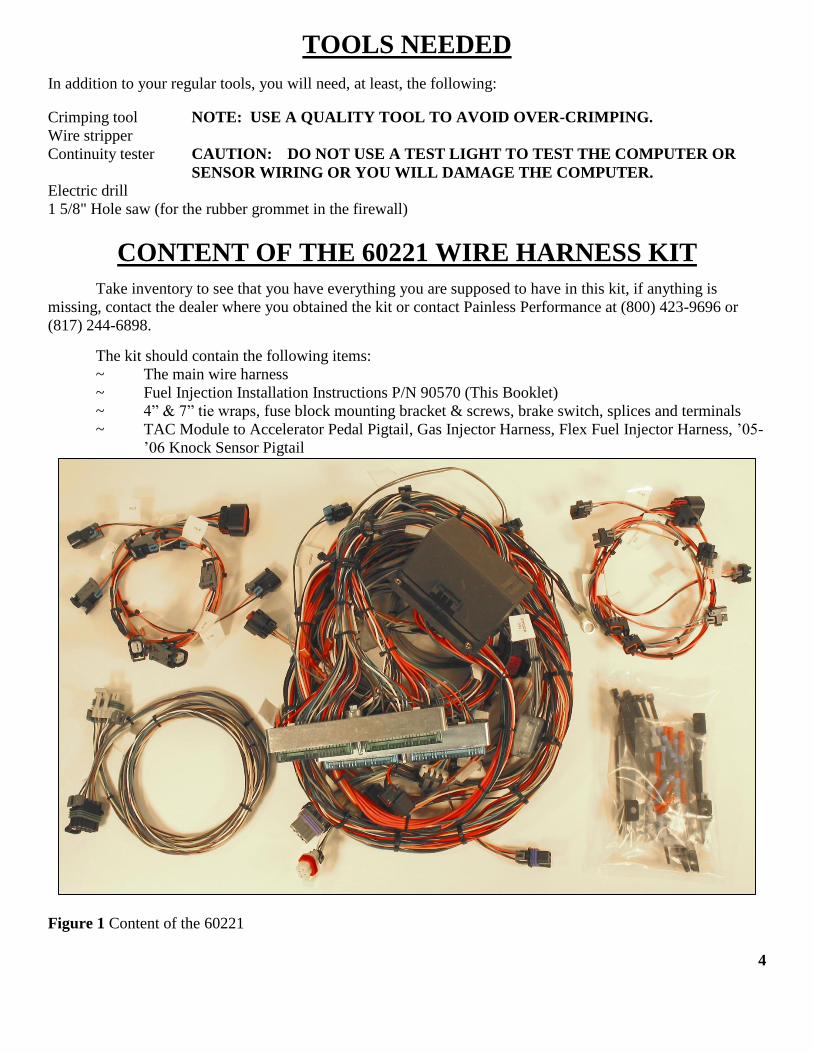
Take inventory to see that you have everything you are supposed to have in this kit, if anything is
missing, contact the dealer where you obtained the kit or contact Painless Performance at (800) 423-9696 or
(817) 244-6898.
The kit should contain the following items:
~ The main wire harness
~ Fuel Injection Installation Instructions P/N 90570 (This Booklet)
~ 4” & 7” tie wraps, fuse block mounting bracket & screws, brake switch, splices and terminals
~ TAC Module to Accelerator Pedal Pigtail, Gas Injector Harness, Flex Fuel Injector Harness, ’05-
’06 Knock Sensor Pigtail
Figure 1 Content of the 60221
4

PRE-INSTALLATION AND HARNESS ROUTING GUIDELINES
Familiarize yourself with the harness by locating each of the harness groups and by looking at the
connectors on the wire ends. A good exercise is to lay out the wire harness on the floor and identify all the
connectors, sections, and wires.
Disconnect the battery if it has not already been disconnected. The sensors and control systems used
by electronic fuel injected vehicles are very sensitive. Any shorts can and will cause severe damage to these
components.
The installation of your harness kit will consist of two parts:
The physical routing, positioning, securing, group/ individual wires and connectors.
The proper electrical connection of the individual circuits.
We cannot tell you how to route the harness in your vehicle. That depends a great deal upon the
particular make of the automobile and what extent you want to secure and conceal the harness. To help you
begin thinking through the installation of your wire harness we can only really offer some general guidelines
and routing practices, general installation instructions in, all of which can be found below.
You will want to route the harness through and around open areas. Inside edges provide extra protection
from hazards and also provide places for tie wraps, clips, and other support.
Route the harness away from sharp edges, exhaust pipes, and the hood, trunk, and door hinges.
Plan where harness supports will be located. Use a support or zip tie approximately every 6 inches.
Allow enough slack in the harness at places where movement could possibly occur (body to frame,
frame to engine, etc.)
HARNESS ATTACHMENT
Note: Harness routing and shaping will be a time-consuming task. Taking your time will enhance the
beauty of your vehicle. Please take your time and be patient.
Mold harness groups to the contour of the dash, engine, frame, etc. Remember to route the harness away
from sharp edges, exhaust pipes, hinges, and moving parts.
Attach harness groups to your vehicle with clips or ties starting at the computer and working your way
outward.
Note: Do not tighten tie wraps or mounting devices until the entire harness is installed. Make all
harness attachments LOOSELY.
Connecting the wires and connectors throughout the harness is a simple process. Make sure that each
wire is properly routed and then attached.
When all the wires are attached, tighten the mounts and ties to secure the harness permanently.
When used every 1-1/2" or so on the visible areas of the harness, plastic wire ties make a very attractive
assembly. Otherwise, a tie installed in other areas every 6" or so will hold the wires in place securely.
REMEMBER TO TAKE YOUR TIME. 5

GROUNDING THE VEHICLE
A perfectly and beautifully wired automobile will nevertheless have problems if everything is not
properly grounded. Don't go to the effort to installing a quality wire harness only to neglect proper grounding.
Note: The installer of this harness is responsible for all ground wires not provided with this part. These
grounds are as followed:
Connect a ground strap or cable (minimum of a 4 Ga. wire) from the negative battery terminal to the
chassis (frame).
Connect a ground strap (minimum of a 4 Ga. wire) from the engine to the chassis (frame). Do not rely
upon the motor mounts to make this connection.
Connect a ground strap from the engine to the body.
INSTALLATION INSTRUCTIONS
Fuse Block, ECM, TAC Module, Pedal Mounting and Connections
Below you will find part numbers for parts compatible with this wire harness.
Main Computer………………….GM #89017733, 12576106, 12583560, or 12602802
TAC Module…………………….GM#12588923
Accelerator Pedal………………..Delco#15264643
Decide where and how the ECM, TAC Module, and fuse block will be mounted. In most cases these
components can be mounted either under the dash or in the kick panel area. All parts are weatherproof
and can be mounted in the engine compartment if necessary.
Take notice of how much distance the harness will allow for ECM and Fuse Block mounting. A bracket
and mounting screws have been included for fuse block mounting. ECM mounting must be handled by
the installer.
The TAC Module and Pedal can both be mounted using the mounting holes found on these components.
The TAC Module must be mounted within 96” of the accelerator pedal, due to the length of the pigtail
contained in the kit, and within 15” of The ECM due to the length given in the harness.
Once these locations have been determined, and double checked for accuracy, mount the ECM, Fuse
Block, TAC Module, and Accelerator Pedal.
Drill a 1-5/8" hole for the firewall grommet near the ECM for the engine group and tail section to pass
through. If the ECM and fuse block are mounted in the engine compartment, a smaller hole and
grommet for the “Dash” portion will be required instead of the 1-5/8” hole . The “Dash” portion of the
harness will not be labeled as such, information on identifying this portion can be found on the next
page.
Route the engine group, cooling fan wires, fuel compensation connector (if used, see p. 15), and tail
section through the hole. Push the grommet (already installed on the harness) into the hole until it is
seated. Again, if the ECM and fuse block are mounted in the engine compartment, the “dash” section of
the harness will pass through this hole.
6
Route the dash group over to the driver's side of the vehicle if it is not already there.
Attach both ECM connectors to the computer. When connecting the plugs to the computer USE
EXTREME CARE to make sure none of the pins in the computer are or become bent.
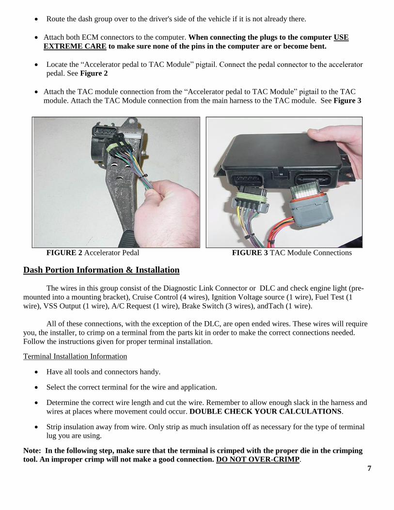
Locate the “Accelerator pedal to TAC Module” pigtail. Connect the pedal connector to the accelerator
pedal. See Figure 2
Attach the TAC module connection from the “Accelerator pedal to TAC Module” pigtail to the TAC
module. Attach the TAC Module connection from the main harness to the TAC module. See Figure 3
FIGURE 2 Accelerator Pedal FIGURE 3 TAC Module Connections
Dash Portion Information & Installation
The wires in this group consist of the Diagnostic Link Connector or DLC and check engine light (pre-
mounted into a mounting bracket), Cruise Control (4 wires), Ignition Voltage source (1 wire), Fuel Test (1
wire), VSS Output (1 wire), A/C Request (1 wire), Brake Switch (3 wires), andTach (1 wire).
All of these connections, with the exception of the DLC, are open ended wires. These wires will require
you, the installer, to crimp on a terminal from the parts kit in order to make the correct connections needed.
Follow the instructions given for proper terminal installation.
Terminal Installation Information
Have all tools and connectors handy.
Select the correct terminal for the wire and application.
Determine the correct wire length and cut the wire. Remember to allow enough slack in the harness and
wires at places where movement could occur. DOUBLE CHECK YOUR CALCULATIONS.
Strip insulation away from wire. Only strip as much insulation off as necessary for the type of terminal
lug you are using.
Note: In the following step, make sure that the terminal is crimped with the proper die in the crimping
tool. An improper crimp will not make a good connection. DO NOT OVER-CRIMP.
7
Crimp the terminal onto the wire and connect.
DLC - The Data Link Connector (DLC) is used to communicate with the ECM. The Powertrain On
Board Diagnostic (OBD) System Check is an organized approach to identifying a problem created by an
electronic powertrain control system malfunction. The Powertrain OBD System Check is the starting point for
any drivability concern diagnosis. The Powertrain OBD System Check directs the installer to the next logical
step in diagnosing a drivability concern. Understanding and using the Powertrain OBD System Check correctly
will reduce the diagnostic time and prevent the replacement of good parts.
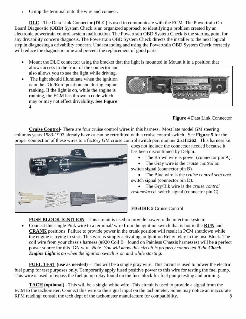
Mount the DLC connector using the bracket that the light is mounted in.Mount it in a position that
allows access to the front of the connector and
also allows you to see the light while driving.
The light should illuminate when the ignition
is in the “On/Run’ position and during engine
ranking. If the light is on, while the engine is
running, the ECM has thrown a code which
may or may not effect drivability. See Figure
4
Figure 4 Data Link Connector
Cruise Control- There are four cruise control wires in this harness. Most late model GM steering
columns years 1983-1993 already have or can be retrofitted with a cruise control switch. See Figure 5 for the
proper connection of these wires to a factory GM cruise control switch part number 25111262. This harness kit
does not include the connector needed because it
has been discontinued by Delphi.
The Brown wire is power (connector pin A).
The Gray wire is the cruise control on
switch signal (connector pin B).
The Blue wire is the cruise control set/coast
switch signal (connector pin D).
The Gry/Blk wire is the cruise control
resume/accel switch signal (connector pin C).
FIGURE 5 Cruise Control
FUSE BLOCK IGNITION - This circuit is used to provide power to the injection system.
Connect this single Pink wire to a terminal/ wire from the ignition switch that is hot in the RUN and
CRANK positions. Failure to provide power in the crank position will result in PCM shutdown while
the engine is trying to start. This wire is simply activating an Ignition Relay relay in the fuse Block. The
coil wire from your chassis harness (#920 Coil B+ found on Painless Chassis harnesses) will be a perfect
power source for this IGN wire. Note: You will know this circuit is properly connected if the Check
Engine Light is on when the ignition switch is on and while starting.
FUEL TEST (use as needed) – This will be a single gray wire. This circuit is used to power the electric
fuel pump for test purposes only. Temporarily apply fused positive power to this wire for testing the fuel pump.
This wire is used to bypass the fuel pump relay found on the fuse block for fuel pump testing and priming.
TACH (optional) - This will be a single white wire. This circuit is used to provide a signal from the
ECM to the tachometer. Connect this wire to the signal input on the tachometer. Some may notice an inaccurate
RPM reading; consult the tech dept of the tachometer manufacture for compatibility. 8
VSS OUTPUT (optional) - This will be a single green/white wire, do not get it confused with the
green/white A/C Request wire. This circuit is used to provide a signal from the PCM to the electric
speedometer. Connect this wire to the signal input on the electric speedometer (not all aftermarket electric
speedometers use the same signal for operation. Consult the tech dept of the speedometer manufacture for
compatibility).
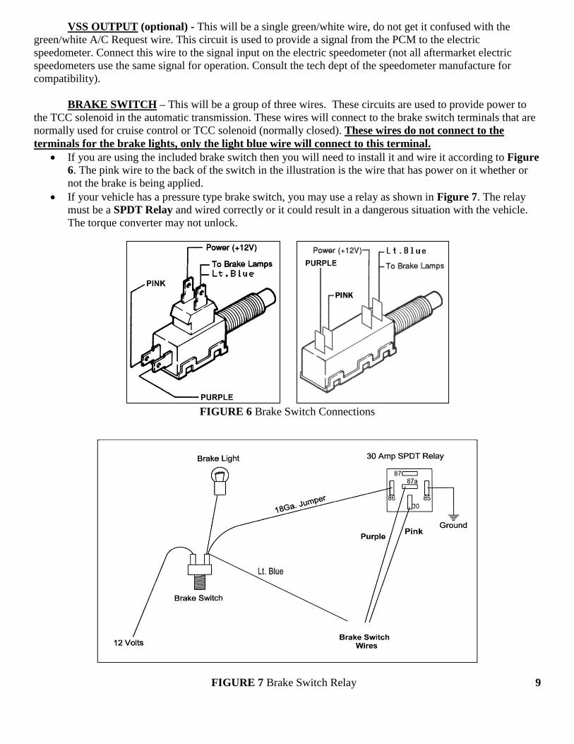
BRAKE SWITCH – This will be a group of three wires. These circuits are used to provide power to
the TCC solenoid in the automatic transmission. These wires will connect to the brake switch terminals that are
normally used for cruise control or TCC solenoid (normally closed). These wires do not connect to the
terminals for the brake lights, only the light blue wire will connect to this terminal.
If you are using the included brake switch then you will need to install it and wire it according to Figure
6. The pink wire to the back of the switch in the illustration is the wire that has power on it whether or
not the brake is being applied.
If your vehicle has a pressure type brake switch, you may use a relay as shown in Figure 7. The relay
must be a SPDT Relay and wired correctly or it could result in a dangerous situation with the vehicle.
The torque converter may not unlock.
FIGURE 6 Brake Switch Connections
FIGURE 7 Brake Switch Relay 9
AC REQUEST – This is not a power supply for the compressor. This circuit is used to inform the
ECM that the AC compressor has been turned on.
This will be a single green/white wire; do not get it confused with the green/white VSS Output wire.
This wire is to be spliced into the circuit from the AC switch to the AC compressor.
ENGINE CONNECTIONS
Painless recommends the use of the listed or equivalent part numbers. These will meet all requirements
and are compatible with the Painless harness. The numbers given are GM and AC Delco part numbers for the
sensors and components found on the ’03-’06 engines.
MAF/ IAT Sensor……………….Delco# 213-364
Engine Coolant Temperature……Delco# 213-953
Throttle Body……………………GM# 12570800
MAP Sensor…………………..…Delco# 213-796
Knock Sensor…………………....Delco# 213-362
Coils………………………….….GM# 10457730
Cam Position Sensor…………….GM# 12561211
Crankshaft Position Sensor……...Delco# 213-354
The engine group is designed to be separated into left (driver) and right (passenger) sections. Each side
is tie-wrapped separately, BUT NOT LABELED. The left side of the engine has the connectors for the
alternator, driver side coils, mass air flow sensor, and engine coolant sensor, all of which ARE labeled. When
you begin routing, FIRST separate the engine group into left and right sections, and place them accordingly.
Note: Before you connect any wires, separate the tail section from the engine group and place it out of the way.
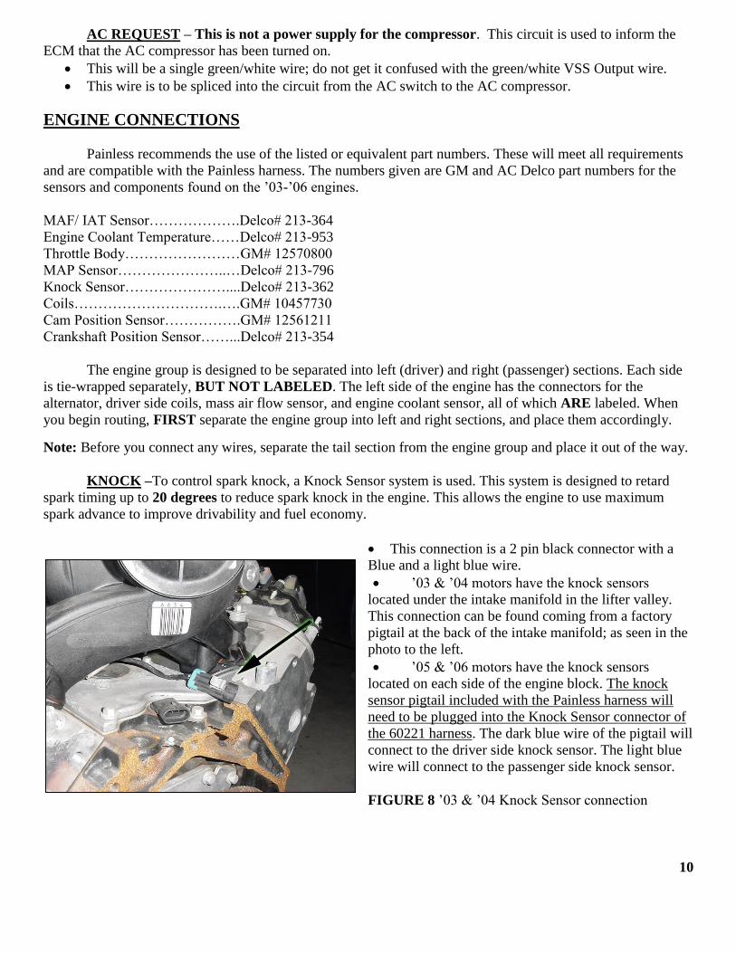
KNOCK –To control spark knock, a Knock Sensor system is used. This system is designed to retard
spark timing up to 20 degrees to reduce spark knock in the engine. This allows the engine to use maximum
spark advance to improve drivability and fuel economy.
This connection is a 2 pin black connector with a
Blue and a light blue wire.
’03 & ’04 motors have the knock sensors
located under the intake manifold in the lifter valley.
This connection can be found coming from a factory
pigtail at the back of the intake manifold; as seen in the
photo to the left.
’05 & ’06 motors have the knock sensors
located on each side of the engine block. The knock
sensor pigtail included with the Painless harness will
need to be plugged into the Knock Sensor connector of
the 60221 harness. The dark blue wire of the pigtail will
connect to the driver side knock sensor. The light blue
wire will connect to the passenger side knock sensor.
FIGURE 8 ’03 & ’04 Knock Sensor connection
10
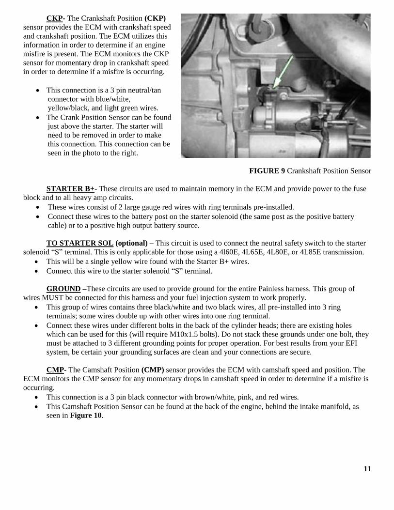
CKP- The Crankshaft Position (CKP)
sensor provides the ECM with crankshaft speed
and crankshaft position. The ECM utilizes this
information in order to determine if an engine
misfire is present. The ECM monitors the CKP
sensor for momentary drop in crankshaft speed
in order to determine if a misfire is occurring.
This connection is a 3 pin neutral/tan
connector with blue/white,
yellow/black, and light green wires.
The Crank Position Sensor can be found
just above the starter. The starter will
need to be removed in order to make
this connection. This connection can be
seen in the photo to the right.
FIGURE 9 Crankshaft Position Sensor
STARTER B+- These circuits are used to maintain memory in the ECM and provide power to the fuse
block and to all heavy amp circuits.
These wires consist of 2 large gauge red wires with ring terminals pre-installed.
Connect these wires to the battery post on the starter solenoid (the same post as the positive battery
cable) or to a positive high output battery source.
TO STARTER SOL (optional) – This circuit is used to connect the neutral safety switch to the starter
solenoid “S” terminal. This is only applicable for those using a 4l60E, 4L65E, 4L80E, or 4L85E transmission.
This will be a single yellow wire found with the Starter B+ wires.
Connect this wire to the starter solenoid “S” terminal.
GROUND –These circuits are used to provide ground for the entire Painless harness. This group of
wires MUST be connected for this harness and your fuel injection system to work properly.
This group of wires contains three black/white and two black wires, all pre-installed into 3 ring
terminals; some wires double up with other wires into one ring terminal.
Connect these wires under different bolts in the back of the cylinder heads; there are existing holes
which can be used for this (will require M10x1.5 bolts). Do not stack these grounds under one bolt, they
must be attached to 3 different grounding points for proper operation. For best results from your EFI
system, be certain your grounding surfaces are clean and your connections are secure.
CMP- The Camshaft Position (CMP) sensor provides the ECM with camshaft speed and position. The
ECM monitors the CMP sensor for any momentary drops in camshaft speed in order to determine if a misfire is
occurring.
This connection is a 3 pin black connector with brown/white, pink, and red wires.
This Camshaft Position Sensor can be found at the back of the engine, behind the intake manifold, as
seen in Figure 10.
11
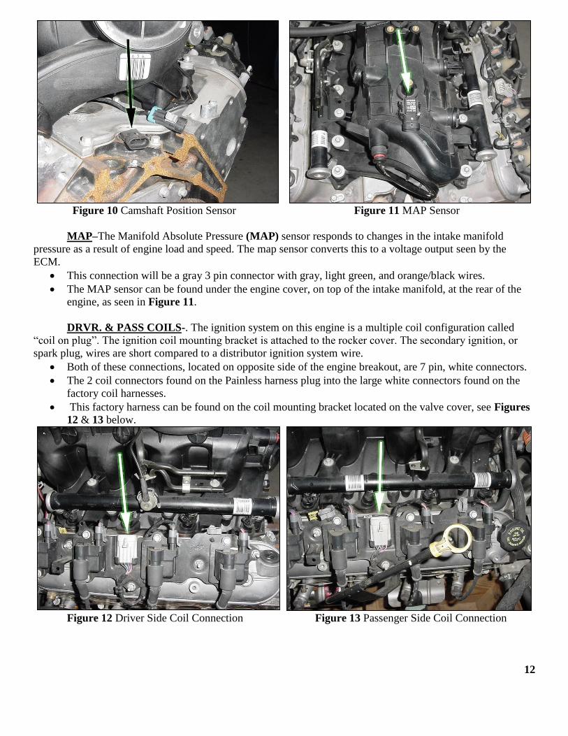
Figure 10 Camshaft Position Sensor Figure 11 MAP Sensor
MAP–The Manifold Absolute Pressure (MAP) sensor responds to changes in the intake manifold
pressure as a result of engine load and speed. The map sensor converts this to a voltage output seen by the
ECM.
This connection will be a gray 3 pin connector with gray, light green, and orange/black wires.
The MAP sensor can be found under the engine cover, on top of the intake manifold, at the rear of the
engine, as seen in Figure 11.
DRVR. & PASS COILS-. The ignition system on this engine is a multiple coil configuration called
“coil on plug”. The ignition coil mounting bracket is attached to the rocker cover. The secondary ignition, or
spark plug, wires are short compared to a distributor ignition system wire.
Both of these connections, located on opposite side of the engine breakout, are 7 pin, white connectors.
The 2 coil connectors found on the Painless harness plug into the large white connectors found on the
factory coil harnesses.
This factory harness can be found on the coil mounting bracket located on the valve cover, see Figures
12 & 13 below.
Figure 12 Driver Side Coil Connection Figure 13 Passenger Side Coil Connection
12
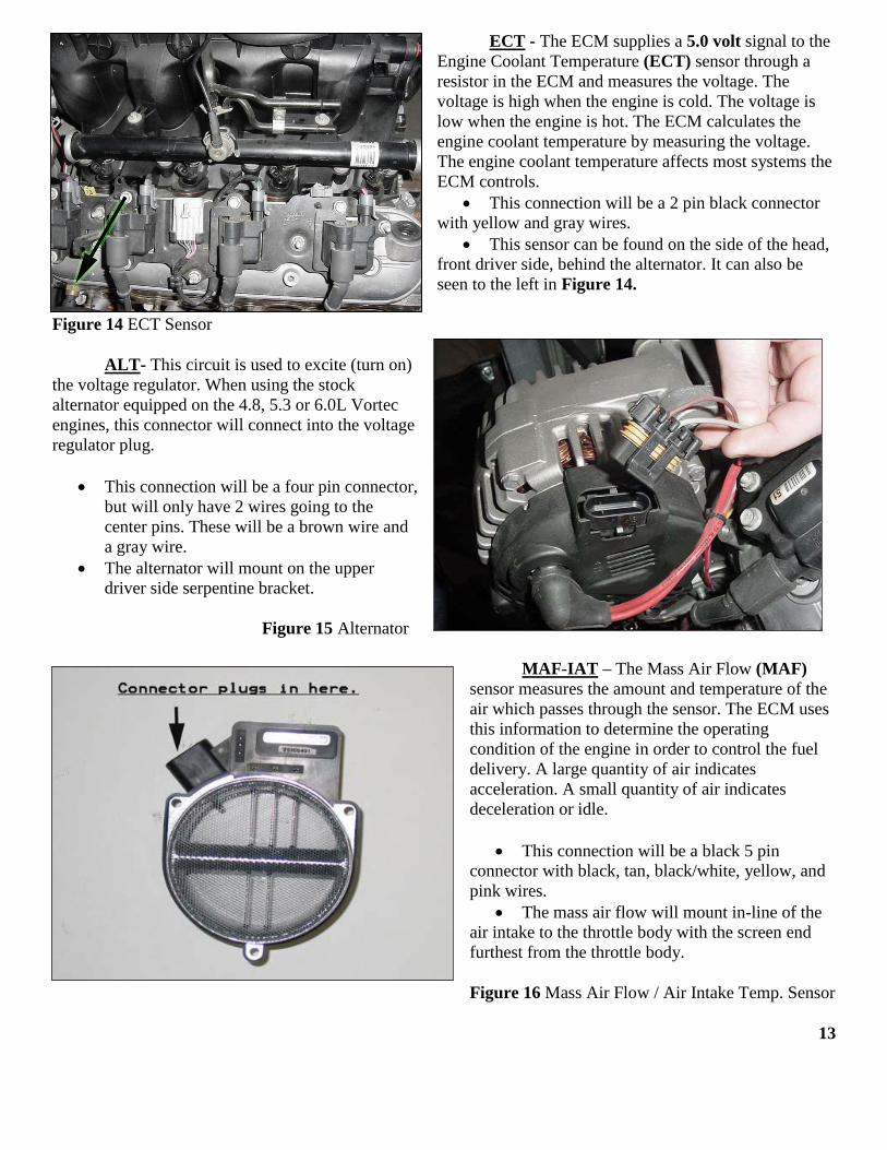
ECT - The ECM supplies a 5.0 volt signal to the
Engine Coolant Temperature (ECT) sensor through a
resistor in the ECM and measures the voltage. The
voltage is high when the engine is cold. The voltage is
low when the engine is hot. The ECM calculates the
engine coolant temperature by measuring the voltage.
The engine coolant temperature affects most systems the
ECM controls.
This connection will be a 2 pin black connector
with yellow and gray wires.
This sensor can be found on the side of the head,
front driver side, behind the alternator. It can also be
seen to the left in Figure 14.
Figure 14 ECT Sensor
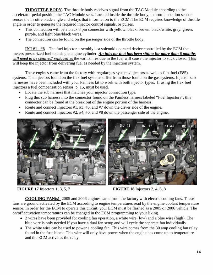
ALT- This circuit is used to excite (turn on)
the voltage regulator. When using the stock
alternator equipped on the 4.8, 5.3 or 6.0L Vortec
engines, this connector will connect into the voltage
regulator plug.
This connection will be a four pin connector,
but will only have 2 wires going to the
center pins. These will be a brown wire and
a gray wire.
The alternator will mount on the upper
driver side serpentine bracket.
Figure 15 Alternator
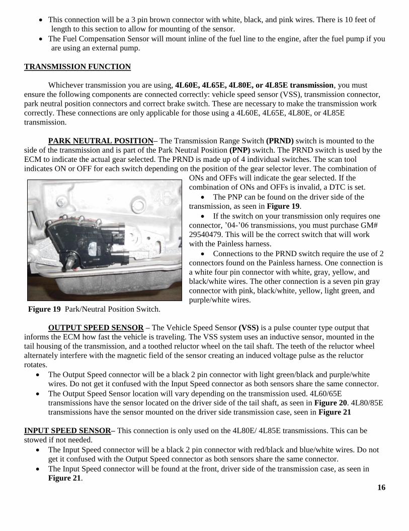
MAF-IAT – The Mass Air Flow (MAF)
sensor measures the amount and temperature of the
air which passes through the sensor. The ECM uses
this information to determine the operating
condition of the engine in order to control the fuel
delivery. A large quantity of air indicates
acceleration. A small quantity of air indicates
deceleration or idle.
This connection will be a black 5 pin
connector with black, tan, black/white, yellow, and
pink wires.
The mass air flow will mount in-line of the
air intake to the throttle body with the screen end
furthest from the throttle body.
Figure 16 Mass Air Flow / Air Intake Temp. Sensor
13
THROTTLE BODY- The throttle body receives signal from the TAC Module according to the
accelerator pedal position the TAC Module sees. Located inside the throttle body, a throttle position sensor
senses the throttle blade angle and relays that information to the ECM. The ECM requires knowledge of throttle
angle in order to generate the required injector control signals, or pulses.
This connection will be a black 8 pin connector with yellow, black, brown, black/white, gray, green,
purple, and light blue/black wires.
The connection can be found on the passenger side of the throttle body.
INJ #1 - #8 – The fuel injector assembly is a solenoid operated device controlled by the ECM that
meters pressurized fuel to a single engine cylinder. An injector that has been sitting for more than 6 months
will need to be cleaned/ replaced as the varnish residue in the fuel will cause the injector to stick closed. This
will keep the injector from delivering fuel as needed by the injection system.
These engines came from the factory with regular gas systems/injectors as well as flex fuel (E85)
systems. The injectors found on the flex fuel systems differ from those found on the gas systems. Injector sub
harnesses have been included with your Painless kit to work with both injector types. If using the flex fuel
injectors a fuel compensation sensor, p. 15, must be used.
Locate the sub harness that matches your injector connection type.
Plug this sub harness into the connector found on the Painless harness labeled “Fuel Injectors”, this
connector can be found at the break out of the engine portion of the harness.
Route and connect Injectors #1, #3, #5, and #7 down the driver side of the engine.
Route and connect Injectors #2, #4, #6, and #8 down the passenger side of the engine.
FIGURE 17 Injectors 1, 3, 5, 7 FIGURE 18 Injectors 2, 4, 6, 8
COOLING FAN(s)- 2005 and 2006 engines came from the factory with electric cooling fans. These
fans are ground activated by the ECM according to engine temperatures read by the engine coolant temperature
sensor. In order for the ECM to operate this circuit, your ECM must be flashed as a 2005 or 2006 vehicle. The
on/off activation temperatures can be changed in the ECM programming to your liking.
2 wires have been provided for cooling fan operation, a white wire (low) and a blue wire (high). The
blue wire is only needed if you have a dual fan setup and will cycle the separate fan individually.
The white wire can be used to power a cooling fan. This wire comes from the 30 amp cooling fan relay
found in the fuse block. This wire will only have power when the engine has come up to temperature
and the ECM activates the relay.
14

The blue wire is simply an activation wire for a separate fan relay. This wire will not power a cooling
fan; it is a ground wire from the ECM which will only activate a fan relay. This wire will need to
connect to the 86 or 85 terminal of a fan relay which is wired to be ground activated. Painless ECM
Controlled Fan Relay kits (#30109 or #30133) are perfect for this.
TAIL/TRANSMISSION GROUP INSTALLATION
O2 Sensors…………………..Delco# AFS106 or equivalent
Range, Park/Neutral Switch….GM# 29540479
Locate the tail section that you earlier separated from the engine group. Begin routing it towards the rear
of the vehicle. Be sure to avoid all sharp edges, moving or hot parts, or anything else that may damage the
harness.
LEFT & RIGHT O2 SENSORS– The ECM uses the signal voltage from heated oxygen sensors in a
Closed Loop to adjust the fuel injector pulse width. In Closed Loop, the ECM adjusts fuel delivery to maintain
an air to fuel ratio which allows the best combination of emission control and drivability.
Sensors used with the Painless harness must be Delco# AFS106 or equivalent.
The connectors for the O2 sensors will be black 4 pin connectors with pink, purple, black, and tan wires.
The driver side O2 connector will have white stripes on the wires.
BACK-UP- This circuit is used to power the back-up lamps. This wire will connect directly to the back-
up light socket. You will need to splice a wire into this circuit in order to accommodate two back-up lights.
This will be a single 3” long light green wire found on the Painless harness near the Park/Neutral
Position Switch.
This wire has been supplied to provide power to the back-up/reverse lights, these wires can be found in
vehicles chassis harness. The chassis harness will have a 12v input and a 12v output to a reverse switch
for reverse light functions. The 12v input is no longer needed.
FROM START SWITCH- This circuit is used to connect the ignition switch, start switch, or start
button to the neutral safety switch. This will enable starting only if the transmission is in park or neutral. This is
only applicable for those using a 4l60E, 4L65E, 4L80E, or 4L85E transmission.
This will be a 3” long purple/white wire found on the Painless harness near the Park/Neutral Position
Switch.
Connect this wire to a circuit from the ignition switch “S” terminal or output side of a start
switch/button. This wire should only have power in the start position.
FUEL PUMP- This circuit provides power to the electric fuel pump. The fuel pump you are using
MUST maintain a constant pressure of 55-62 P.S.I. (pounds per square inch). ’03 & ’04 engine have a built-in
regulator on the fuel rail as in many earlier GM fuel injection systems. ’05 & ’06 engines will require an
external regulator.
This wire will be a open ended, large gauge gray wire. It comes from the output side of the fuse block
mounted fuel pump relay.
Connect this wire to the positive side of the electric fuel pump.
FUEL COMPENSATION SENSOR- The fuel composition sensor, or flex fuel sensor, measures the
ethanol-gasoline ratio of the fuel being used in a flexible fuel vehicle. Flexible fuel vehicles can be operated
with a blend of ethanol and gasoline, up to 85 percent ethanol. In order to adjust the ignition timing and the fuel
quantity to be injected, the ECM requires information about the percentage of ethanol in the fuel. This sensor
must be used in order to run E85 fuel and your engine must be equipped with flex fuel injectors.(2003-2005
engines only, 2006 ECMs must be flashed for a ’05 in order to use the flex fuel feature) 15
This connection will be a 3 pin brown connector with white, black, and pink wires. There is 10 feet of
length to this section to allow for mounting of the sensor.
The Fuel Compensation Sensor will mount inline of the fuel line to the engine, after the fuel pump if you
are using an external pump.
TRANSMISSION FUNCTION
Whichever transmission you are using, 4L60E, 4L65E, 4L80E, or 4L85E transmission, you must
ensure the following components are connected correctly: vehicle speed sensor (VSS), transmission connector,
park neutral position connectors and correct brake switch. These are necessary to make the transmission work
correctly. These connections are only applicable for those using a 4L60E, 4L65E, 4L80E, or 4L85E
transmission.
PARK NEUTRAL POSITION– The Transmission Range Switch (PRND) switch is mounted to the
side of the transmission and is part of the Park Neutral Position (PNP) switch. The PRND switch is used by the
ECM to indicate the actual gear selected. The PRND is made up of 4 individual switches. The scan tool
indicates ON or OFF for each switch depending on the position of the gear selector lever. The combination of
ONs and OFFs will indicate the gear selected. If the
combination of ONs and OFFs is invalid, a DTC is set.
The PNP can be found on the driver side of the
transmission, as seen in Figure 19.
If the switch on your transmission only requires one
connector, ’04-’06 transmissions, you must purchase GM#
29540479. This will be the correct switch that will work
with the Painless harness.
Connections to the PRND switch require the use of 2
connectors found on the Painless harness. One connection is
a white four pin connector with white, gray, yellow, and
black/white wires. The other connection is a seven pin gray
connector with pink, black/white, yellow, light green, and
purple/white wires.
Figure 19 Park/Neutral Position Switch.
OUTPUT SPEED SENSOR – The Vehicle Speed Sensor (VSS) is a pulse counter type output that
informs the ECM how fast the vehicle is traveling. The VSS system uses an inductive sensor, mounted in the
tail housing of the transmission, and a toothed reluctor wheel on the tail shaft. The teeth of the reluctor wheel
alternately interfere with the magnetic field of the sensor creating an induced voltage pulse as the reluctor
rotates.
The Output Speed connector will be a black 2 pin connector with light green/black and purple/white
wires. Do not get it confused with the Input Speed connector as both sensors share the same connector.
The Output Speed Sensor location will vary depending on the transmission used. 4L60/65E
transmissions have the sensor located on the driver side of the tail shaft, as seen in Figure 20. 4L80/85E
transmissions have the sensor mounted on the driver side transmission case, seen in Figure 21
INPUT SPEED SENSOR– This connection is only used on the 4L80E/ 4L85E transmissions. This can be
stowed if not needed.
The Input Speed connector will be a black 2 pin connector with red/black and blue/white wires. Do not
get it confused with the Output Speed connector as both sensors share the same connector.
The Input Speed connector will be found at the front, driver side of the transmission case, as seen in
Figure 21.
16
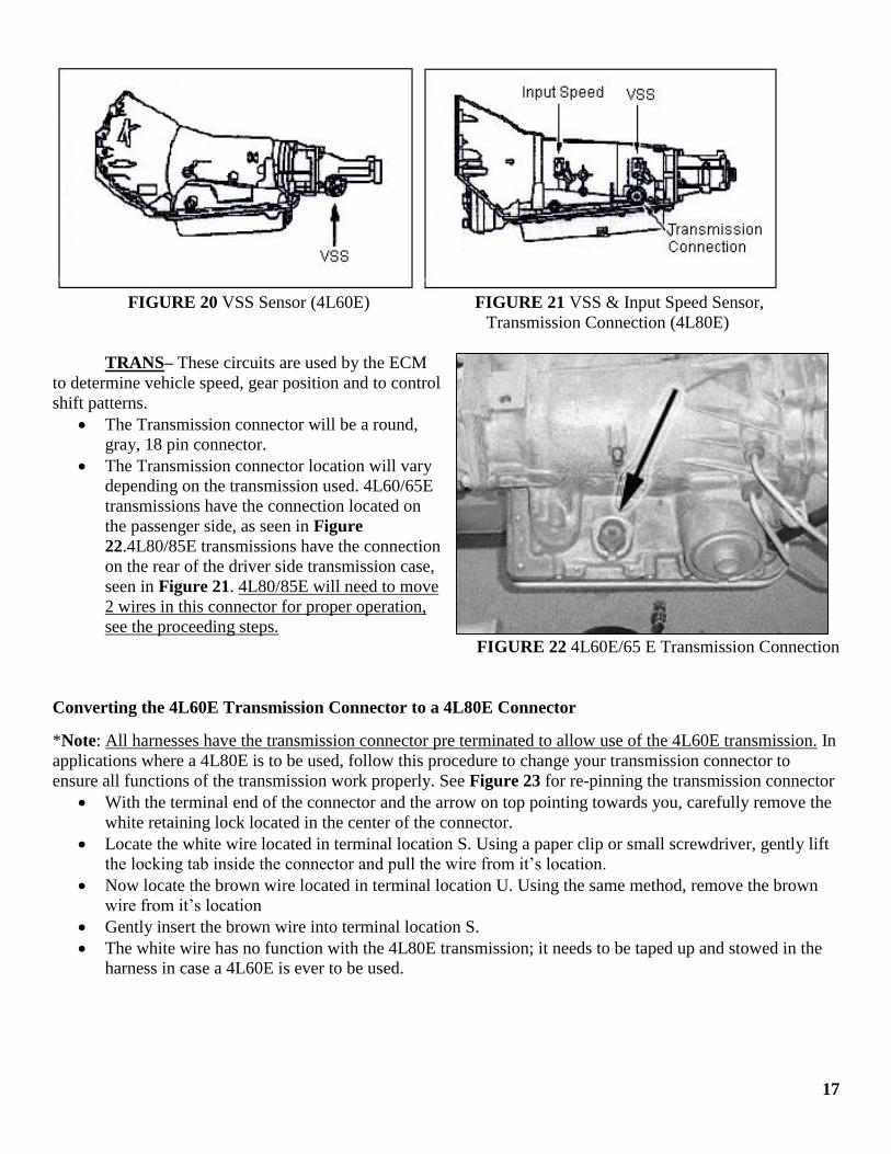
FIGURE 20 VSS Sensor (4L60E) FIGURE 21 VSS & Input Speed Sensor,
Transmission Connection (4L80E)
TRANS– These circuits are used by the ECM
to determine vehicle speed, gear position and to control
shift patterns.
The Transmission connector will be a round,
gray, 18 pin connector.
The Transmission connector location will vary
depending on the transmission used. 4L60/65E
transmissions have the connection located on
the passenger side, as seen in Figure
22.4L80/85E transmissions have the connection
on the rear of the driver side transmission case,
seen in Figure 21. 4L80/85E will need to move
2 wires in this connector for proper operation,
see the proceeding steps.
FIGURE 22 4L60E/65 E Transmission Connection
Converting the 4L60E Transmission Connector to a 4L80E Connector
*Note: All harnesses have the transmission connector pre terminated to allow use of the 4L60E transmission. In
applications where a 4L80E is to be used, follow this procedure to change your transmission connector to
ensure all functions of the transmission work properly. See Figure 23 for re-pinning the transmission connector
With the terminal end of the connector and the arrow on top pointing towards you, carefully remove the
white retaining lock located in the center of the connector.
Locate the white wire located in terminal location S. Using a paper clip or small screwdriver, gently lift
the locking tab inside the connector and pull the wire from it’s location.
Now locate the brown wire located in terminal location U. Using the same method, remove the brown
wire from it’s location
Gently insert the brown wire into terminal location S.
The white wire has no function with the 4L80E transmission; it needs to be taped up and stowed in the
harness in case a 4L60E is ever to be used.
17
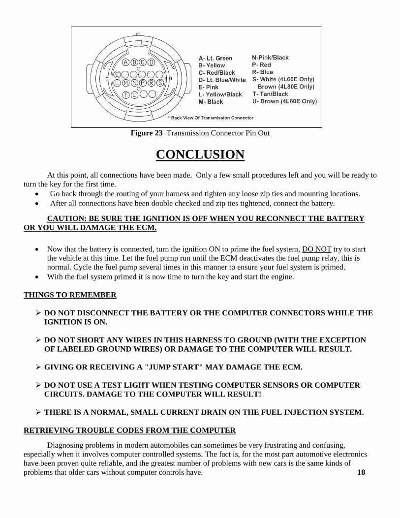
Figure 23 Transmission Connector Pin Out
CONCLUSION
At this point, all connections have been made. Only a few small procedures left and you will be ready to
turn the key for the first time.
Go back through the routing of your harness and tighten any loose zip ties and mounting locations.
After all connections have been double checked and zip ties tightened, connect the battery.
CAUTION: BE SURE THE IGNITION IS OFF WHEN YOU RECONNECT THE BATTERY
OR YOU WILL DAMAGE THE ECM.
Now that the battery is connected, turn the ignition ON to prime the fuel system, DO NOT try to start
the vehicle at this time. Let the fuel pump run until the ECM deactivates the fuel pump relay, this is
normal. Cycle the fuel pump several times in this manner to ensure your fuel system is primed.
With the fuel system primed it is now time to turn the key and start the engine.
THINGS TO REMEMBER
DO NOT DISCONNECT THE BATTERY OR THE COMPUTER CONNECTORS WHILE THE
IGNITION IS ON.
DO NOT SHORT ANY WIRES IN THIS HARNESS TO GROUND (WITH THE EXCEPTION
OF LABELED GROUND WIRES) OR DAMAGE TO THE COMPUTER WILL RESULT.
GIVING OR RECEIVING A "JUMP START" MAY DAMAGE THE ECM.
DO NOT USE A TEST LIGHT WHEN TESTING COMPUTER SENSORS OR COMPUTER
CIRCUITS. DAMAGE TO THE COMPUTER WILL RESULT!
THERE IS A NORMAL, SMALL CURRENT DRAIN ON THE FUEL INJECTION SYSTEM.
RETRIEVING TROUBLE CODES FROM THE COMPUTER
Diagnosing problems in modern automobiles can sometimes be very frustrating and confusing,
especially when it involves computer controlled systems. The fact is, for the most part automotive electronics
have been proven quite reliable, and the greatest number of problems with new cars is the same kinds of
problems that older cars without computer controls have. 18

Begin all troubleshooting by checking the basics. Certain basic faults may be undetectable by the ECM
self-diagnostic system and can actually interfere with self-checking and fault memory operation. Low battery
voltage, for example, can cause erroneous faults to set in ECM memory or can cause a system to go "Fail Safe"
without setting a fault in memory. Because system faults memory is cleared whenever ECM or battery are
disconnected, fault codes should be read prior to any vehicle power interruption or troubleshooting.
Before suspecting a computer problem, perform a careful visual inspection. Check under the hood for
the same kinds of problems you would look for on a non-computer controlled engine. These include fluid leaks,
vacuum leaks, dirty filters, overheating, oil burning, poor connections or loose wires, bad spark plug wires
and/or spark plugs, restricted mufflers and exhaust systems, worn mechanical parts, exhaust leaks, and other
familiar kinds of problems. Be thorough! You may save a lot of time.
PROCEDURE A Tech II or equivalent Scan tool must be used to check or clear Diagnostic Trouble Codes (DTCs) from the
ECM memory. When clearing DTCs, follow the instructions supplied by the Scan tool manufacturer.
We have attempted to provide you with the most accurate instructions
possible, and are always concerned about corrections or improvements that
can be made. If you have found any errors or omissions, or if you simply have
comments or suggestions concerning these instructions, please write us at the
address on the cover and let us know about them. Or, better yet, send us a fax
at (817) 244-4024. We sincerely appreciate your business.
Painless Performance Limited Warranty
and Return Policy
Chassis harnesses, fuel injection harnesses, and Striker ColdShot units are covered under a lifetime warranty.
All other products manufactured and/or sold by Painless Performance are warranted to the original purchaser to
be free from defects in material and workmanship under normal use. Painless Performance will repair or replace
defective products without charge during the first 12 months from the purchase date. No products will be
considered for warranty without a copy of the purchase receipt showing the sellers name, address and date of
purchase. You must return the product to the dealer you purchased it from to initiate warranty procedures. 19

NOTES: