Embed Size (px)
Citation preview
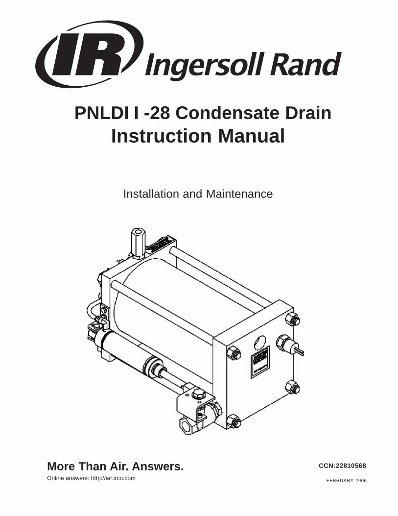
PNLDII-28 Condensate DrainInstruction Manual
Installation and Maintenance
More Than Air. Answers.Online answers: http://air.irco.com
CCN:22810568
FEBRUARY 2006

Page 2
http://air.irco.com
Limited One Year Warranty This product is warranted to be free from defects in material and workmanship, under proper use, installation, application, and maintenance in accordance with the manufacturer’s written recommendations and specification for a period of 18 months from the date of shipment from the factory or 12 months from the date of installation, whichever comes first. The manufacturer’s obligation under this warranty is limited to, and the sole remedy for any such defect shall be, the repair or replacement (at manufacturer’s option) of unaltered products returned to manufacturer within stated period. In order to process a claim, Ingersoll Rand must get from the customer a proof of purchase (date of purchase, invoice number). In no event, shall Ingersoll Rand be liable for business interruptions, loss of profits, personal injury, costs of delay or any other special, indirect, incidental, or consequential losses, cost, or damages. NOTE - Routine maintenance and minor adjustments to this product are not covered under this warranty. Prior to performing any possible warranty service or replacing a possible warranted part, please contact your local Ingersoll Rand authorized representative. All warranty claims must be performed by an Ingersoll Rand certified technician. Failure to comply with this procedure will result in denial of warranty claim.

Page 3
http://air.irco.com
PRODUCT DESCRIPTION
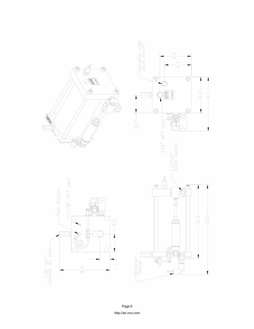
The PNLDII-28 is designed for trouble-free and maintenance- free draining of unwanted accumulations of condensation and other foreign matter from any collection point in a compressed air system without the need for electricity.
INSTALLATION
CAUTION: COMPRESSED AIR CAN BE DANGEROUS.
Before attempting to install the drain, be certain that the pressure vessel on which the drain will be installed is completely depressurized.
The drain should not be installed in areas that are exposed to freezing temperatures (heater option is available). Be certain the air system pressure does not exceed the 300 PSI working pressure of the drain and the pressure to the control system does not exceed 130 psi. The inlet temperature should not exceed 180 degrees F.
Connecting the drain to the air system should be done by using one of the recommended installation diagrams shown herein. The installation of a strainer is not required or recommended.
Install the drain as close to the source to be drained as possible. Since the PNLDII-28 uses gravity to fill the reservoir, the entire drain must be installed below the vessel to be drained when using the top inlet. If flexible tubing is used on the discharge, be certain it is properly fastened to prevent it from whipping when the drain discharges the condensation.
The PNLDII-28 will accept condensation from either the top or the bottom of the reservoir. We recommend the use of the top entry port. If the bottom inlet is used, then a vent line must be used. The vent line should be installed down stream from the vessel that is being drained. This will insure that the air in the reservoir will properly exit as the condensation fills the tank and replaces the air. Install the vent line in the 1/8" port located on the side of drain. The other end of the vent line should be run back to the air system to a point just down stream from the source that is being drained. Use non-galling pipe sealant on all joints. The use of shut-off valves, unions and bypass valves is recommended. A backup wrench should be used on the discharge ball valve to prevent it from turning and causing the linkage to bind.
The inlet port that is not used must be plugged by using a standard 3/4" npt plug. When using the top inlet, any reduction in the 3/4"pipe size is not recommended and the PNLDII-28 reservoir cannot be higher than the bottom of the vessel that is being drained. It is best to run the drain in a downward pitch from the bottom of the vessel being drained to the PNLDII-28 inlet.
The power to operate the PNLDII-28 comes from compressed air. ONLY CLEAN DRY AIR SHOULD BE USED. The supply pressure should be between 55 and 130 psig.
The PNLDII-28 is supplied with an inlet filter, which should be installed in the PNLDII-28 head. The use of unfiltered air can cause the drain to fail.
Once the drain is installed, close the By-Pass drain valve and open the Shut-Off valve. The pressure vessel can now be repressurized.
CHECKING THE DRAIN'S OPERATION
After installation is complete and the drain is on line, a check should be made that the condensation is properly entering the reservoir. This can easily be done by looking through the translucent reservoir.
If condensation is not entering the reservoir, check for the following:
1. Make sure the auxiliary shut-off valve is open.
2. Do not use the bottom inlet on the PNLDII-28 without installing a vent line.
3. If a vent line is installed, make sure it is down stream from the vessel that is being drained.
4. Be certain that the PNLDII-28 reservoir is not higher than the vessel that is being drained. This is very important when using the top inlet on the PNLDII-28 reservoir.
5. Check to make sure the vessel being drained has condensation in it.
If the top inlet is being used and no condensation is entering the PNLDII-28 reservoir, and all the above items have been checked, we recommend that the bottom inlet be used with a vent line out of the top.
If condensate fills the reservoir and the drain does not operate, check to see if control line air is supplied to control line port. If the drain is supplied with an optional test button, the supply of control line air can be checked by pushing the test button. If the unit does not operate, then no air is being supplied or the inlet filter is plugged.
OPTIONS
• Cycle Counter
• High Level Alarm
• Heater
WARRANTY
The PNLDII-28 is warranted to be free from defects in workmanship and materials for a period of one year from the date of shipment. The liability of the manufacturer is limited to repair or replacement of the drain at its option. In no event shall the manufacturer be liable for special or consequential damages or for delay in performances of this warranty.
CAUTION: Any attempt to repair the drain without authorization will void any warranty.
Page 4
http://air.irco.com
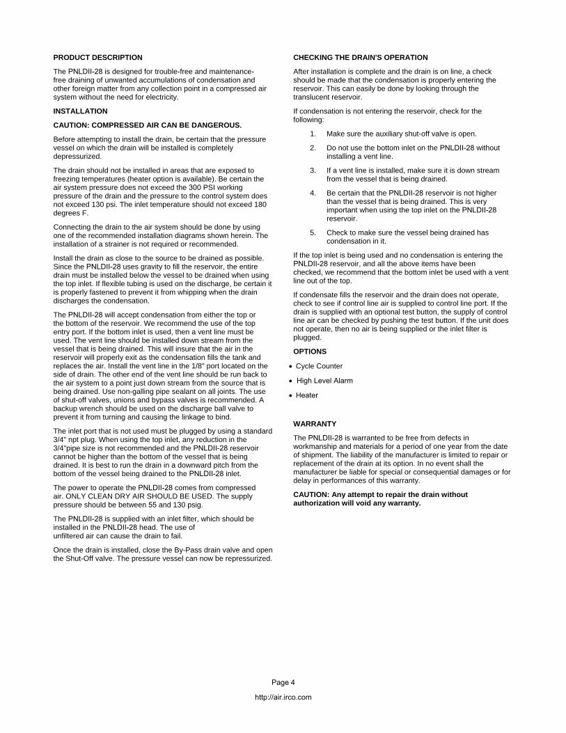
IN GENERAL
In order for the condensate to properly enter the PNLDII-28 reservoir, the condensate line to the PNLDII-28 must always be installed below the bottom of the vessel to be drained. It is equally important to provide a means for the air that is contained in the reservoir to escape (vent) as the condensate enters the reservoir. If the air can not escape, the condensate will not enter the reservoir. Below are suggestions on how to best install the PNLDII-28 on typical types of vessels that have to drained of condensate. However, it is possible to install the PNLDII-28 without a balance line, providing the condensate enters the top inlet and the flow rates are less than 9 GPH (750 cfm for an aftercooler or 1500 cfm drier) for a 1/2" drain line and 19 GPH (1500 cfm for an aftercooler or 3000 cfm drier) for a 3/4" line. The use of unions and shut-off valves are recommended for both the condensate line and the balance line.
RECEIVER TANK
The preferred installation for a PNLDII-28 on a receiver tank is having the condensate enter the top inlet port and having the balance line go back to the tank at a position that is above the level of the condensate (Dwg. 1).
FILTER and AFTERCOOLER MOISTURE SEPARATOR
If a cyclone separator or filter has pipe plugs located in the top of the Dwg. 2 head, the plug closest to the discharge pipe should be removed and the balance line should be installed (Dwg. 2). If there is no provision on the cyclone separator or filter for a balance line, install it in the discharge side of the pipe line and as close to the cyclone separator as possible.
REFRIGERATED DRYER
If a balance line is required, it must be connected to the port located on top of the separator that is closest to the discharge side (Dwg. 2), or between the Vent Line separator and the air-to-air heat exchanger. If a port is not available as described above, then venting to atmosphere is recommended. When venting to atmosphere, the condensate should enter through the bottom entry port on the drain. The bleed or needle valve is installed on the 1/8" NPT vent port and allows the air in the PNLDII-28 reservoir to escape to the atmosphere (Dwg. 3). The bleed valve should be adjusted so that only 3 to 5bubbles per second are visible. We do not recommend installing a vent line down stream from the dryer. The vent line can be a conduit for transferring moisture from the drain to the previously dried air. This can result in unwanted moisture being sent down stream.
INTERCOOLERS
Install the condensate drain line into the upper port only. This will prevent the possibility of condensate being drawn back into the intercooler on some systems. It is important that the vent line be installed on the same stage that is being drained or to atmosphere.
BALANCE LINE
As mentioned above, both the use and the placement of a balance line is very important. Most drain failures are the result of an improper balance line installation. The balance line should be 1/4" tubing or larger, and installed on top of a pipe or vessel, not the bottom. A needle valve is recommended for controlling the air flow. Avoid having any loops or low areas in the balance line that might allow moisture to collect in the line and prevent the passage of air from the drains reservoir.
DWG. 1
DWG. 2
DWG. 3
Page 5
http://air.irco.com
Page 6
http://air.irco.com

ITEM
CC
ND
ESC
RIP
TIO
NQ
TY.
138
4408
89C
ON
TRO
L H
EA
D A
SS
EM
BLY
12
3844
0897
INLE
T H
EA
D A
SS
EM
BLY
13
3844
0905
FRP
CY
LIN
DE
R1
438
4409
13R
ING
AN
D F
ILTE
R K
IT1
538
4409
21TI
E R
OD
KIT
16
3844
0939
CO
NTR
OL
AS
SE
MB
LY1
738
4409
47C
ON
TRO
L TU
BIN
G A
SS
EM
BLY
18
3844
0954
AIR
CY
LIN
DE
R A
SS
EM
BLY
19
3844
0962
BA
LL V
ALV
E A
SS
EM
BLY
1
Page 7
http://air.irco.com
Disclaimer: Nothing contained within this brochure is intended to extend anywarranty or representation, expressed or implied regarding the productsdescribed herein. Any such warranty or other items or conditions of productsshall be in accordance with Ingersoll-Rand Standard Terms and Conditions ofSale for such products, which are available upon request.Product Improvement is a continuing goal at Ingersoll-Rand. Designs andspecifications are subject to change without notice or obligation.
c Ingersoll Rand 2006. Printed in USA.
DISTRIBUTED BY:
Ingersoll-Rand Co. LtdSwan Lane, Hindley GreenWigan WN2 4EZ, United KingdomTel: +44 (0) 1942 257171Fax: +44 (0) 1942 254162www.ingersoll-rand.com
Ingersoll-Rand Company800-A Beaty Street, P.O. Box 1600Davidson, NC 28036 USATel: +1 (704) 896 4000Fax: +1 (704) 896 4648