Embed Size (px)
Citation preview
D e v e l o p e r N o t e
Power Mac G4
September 17, 2002
Apple Computer, Inc.© 2001, 2002 Apple Computer, Inc.All rights reserved. No part of this publication may be reproduced, stored in a retrieval system, or transmitted, in any form or by any means, mechanical, electronic, photocopying, recording, or otherwise, without prior written permission of Apple Computer, Inc., with the following exceptions: Any person is hereby authorized to store documentation on a single computer for personal use only and to print copies of documentation for personal use provided that the documentation contains Apple’s copyright notice. The Apple logo is a trademark of Apple Computer, Inc. Use of the “keyboard” Apple logo (Option-Shift-K) for commercial purposes without the prior written consent of Apple may constitute trademark infringement and unfair competition in violation of federal and state laws. No licenses, express or implied, are granted with respect to any of the technology described in this book. Apple retains all intellectual property rights associated with the technology described in this book. This book is intended to assist application developers to develop applications only for Apple-labeled or Apple-licensed computers.Every effort has been made to ensure that the information in this document is accurate. Apple is not responsible for typographical errors.Apple Computer, Inc.1 Infinite LoopCupertino, CA 95014408-996-1010Apple, the Apple logo, AirPort, FireWire, the FireWire logo, Mac, Macintosh, Power Macintosh, and Power Mac are trademarks of Apple Computer, Inc., registered in the United States and other countries.
Apple Pro Speakers, SuperDrive, and Velocity Engine are trademarks of Apple Computer, Inc.OpenGL is a registered trademark of Silicon Graphics, Inc.PowerPC is a trademark of International Business Machines Corporation, used under license therefrom.Simultaneously published in the United States and Canada
Even though Apple has reviewed this manual, APPLE MAKES NO WARRANTY OR REPRESENTATION, EITHER EXPRESS OR IMPLIED, WITH RESPECT TO THIS MANUAL, ITS QUALITY, ACCURACY, MERCHANTABILITY, OR FITNESS FOR A PARTICULAR PURPOSE. AS A RESULT, THIS MANUAL IS SOLD “AS IS,” AND YOU, THE PURCHASER, ARE ASSUMING THE ENTIRE RISK AS TO ITS QUALITY AND ACCURACY.
IN NO EVENT WILL APPLE BE LIABLE FOR DIRECT, INDIRECT, SPECIAL, INCIDENTAL, OR CONSEQUENTIAL DAMAGES RESULTING FROM ANY DEFECT OR INACCURACY IN THIS MANUAL, even if advised of the possibility of such damages.
THE WARRANTY AND REMEDIES SET FORTH ABOVE ARE EXCLUSIVE AND IN LIEU OF ALL OTHERS, ORAL OR WRITTEN, EXPRESS OR IMPLIED. No Apple dealer, agent, or employee is authorized to make any modification, extension, or addition to this warranty.
Some states do not allow the exclusion or limitation of implied warranties or liability for incidental or consequential damages, so the above limitation or exclusion may not apply to you. This warranty gives you specific legal rights, and you may also have other rights which vary from state to state.
3
Apple Computer, Inc. September 17, 2002
Contents
Figures and Tables 7
Preface
About This Note
9
Chapter 1
Introduction
11
New Features 11Hardware Features Summary 12Features of the Enclosure 15System Software 15
Computer Identification 16Dual Processors and Mac OS 9 Applications 16Power-Saving Modes 17
Processor States 17System Modes 17
Velocity Engine Acceleration 18
Chapter 2
Architecture
19
Block Diagram and Buses 19Processor Module 21
PowerPC G4 Microprocessor 21Cache Memory 22Dual Processors 22
U2 Bridge and Memory Controller 23Processor Bus 23Main Memory Bus 24Ultra ATA/100 Interface 24Accelerated Graphics Port Bus 25PCI Bus 25
4
Apple Computer, Inc. September 17, 2002
C O N T E N T S
Boot ROM 26Ethernet Controller 26FireWire Controllers 26
KeyLargo I/O Controller 27DMA Support 27Interrupt Support 27USB Interface 28Ultra ATA/66 Interface 28Enhanced IDE Interface 28Wireless LAN Module 29Modem Slot Support 29Sound Circuitry 29Power Controller 30
Graphics Cards 31
Chapter 3
Input and Output Devices
33
USB Ports 33USB Connectors 34Waking Up From Sleep 35Booting From USB Storage Devices 35
FireWire Ports 366-Pin FireWire Connector 36Booting from a FireWire Device 38Target Disk Mode 38
Ethernet Port 39Disk Drives 41
Removable-Media Drives 41SuperDrive 42Combo (DVD-ROM/CD-RW) Drive 43
Fixed-Media Drives 43Optional Ultra SCSI 160 Drive 44
Internal Modem 44AirPort Card 45
Data Security 45AirPort Hardware 46AirPort Software 46
C O N T E N T S
5
Apple Computer, Inc. September 17, 2002
Keyboard 47Keyboard Features 47Keyboard Layout 47MultiMedia Control Keys 48Keyboard and USB 48Programmer’s Switches 49
Mouse 49Sound System 50
Audio Input Jack 51Headphone Jack 52Audio Output Jack 52Apple Pro Speakers Minijack 53
Video Monitor Ports 54Apple Display Connector 54DVI Connector 56
Chapter 4
Expansion
59
RAM Expansion 59DIMM Specifications 60
Mechanical Specifications 60Electrical Specifications 60
DIMM Configurations 61RAM Addressing 62
PCI Expansion Slots 62
Appendix A
Supplemental Reference Documents
65
Apple Technical Notes 65PowerPC G4 Microprocessor 65Velocity Engine (AltiVec) 66Multiprocessing Services 663D Graphics 67Mac OS X 67Mac OS 9.2.2 68ROM-in-RAM Architecture 68
6
Apple Computer, Inc. September 17, 2002
C O N T E N T S
Open Firmware 69RAM Expansion Modules 70ATA Devices 70USB Interface 71FireWire Interface 71Digital Visual Interface 72Wireless Networks 72
Appendix B
Conventions and Abbreviations
73
Typographical Conventions 73Abbreviations 73
Index
77
7
Apple Computer, Inc. September 17, 2002
Figures and Tables
Chapter 2
Architecture
19
Figure 2-1 Simplified block diagram 20
Chapter 3
Input and Output Devices
33
Figure 3-1 USB connector 34Figure 3-2 6-pin FireWire connector 37Figure 3-3 ANSI keyboard layout 48Figure 3-4 Apple display connector 55Figure 3-5 DVI connector 57Table 3-1 Signals on the USB connector 34Table 3-2 Signals on the 6-pin FireWire connector 37Table 3-3 Signals for 10Base-T and 100Base-T operation 40Table 3-4 Signals for 1000Base-T operation 40Table 3-5 Media read and written by the SuperDrive 42Table 3-6 Media read and written by the Combo drive 43Table 3-7 Digital signals on the Apple display connector 55Table 3-8 Analog signals on the Apple display connector 56Table 3-9 Signals on the DVI connector 57
Chapter 4
Expansion
59
Table 4-1 Sizes of DDR SDRAM expansion DIMMS and devices 61Table 4-2 Address multiplexing modes for SDRAM devices 62

8
Apple Computer, Inc. September 17, 2002
F I G U R E S A N D T A B L E S
9
Apple Computer, Inc. September 17, 2002
P R E F A C E
About This Note
This developer note describes the Power Mac G4 computer. The note provides information about the internal design of the computer, its input-output and expansion capabilities, and issues affecting compatibility.
This developer note is intended to help hardware and software developers design products that are compatible with the Macintosh products described here. If you are not already familiar with Macintosh computers or if you would simply like additional technical information, refer to Appendix A, “Supplemental Reference Documents” (page 65), for additional information.
The information is arranged in four chapters and two appendixes:
Chapter 1, “Introduction” (page 11), gives a summary of the features of the Power Mac G4 computer, describes the physical appearance of the enclosure, and lists compatibility issues of interest to developers.
Chapter 2, “Architecture” (page 19), describes the internal organization of the computer. It includes a functional block diagram and descriptions of the main components on the logic board.
Chapter 3, “Input and Output Devices” (page 33), describes the built-in I/O devices and the external I/O ports.
Chapter 4, “Expansion” (page 59), describes the expansion slots on the logic board and provides specifications for the expansion modules.
Appendix A, “Supplemental Reference Documents” (page 65), provides sources of additional information about the technologies used in the Power Mac G4 computer.
Appendix B, “Conventions and Abbreviations” (page 73), lists standard units of measure and other abbreviations used in this developer note.

10
Apple Computer, Inc. September 17, 2002
P R E F A C E
About This Note
New Features
11
Apple Computer, Inc. September 17, 2002
C H A P T E R 1
1 Introduction
The desktop Power Mac G4 computer uses dual PowerPC G4 microprocessors and is intended for use in content creation, desktop publishing, multimedia, and other activities that require high performance.
New Features
Here is a list of the features that are new to the Power Mac G4 computer.
Microprocessor clock speed:
The clock frequency is dual 867 MHz, 1 GHz, or 1.25 GHz. For more information, see “PowerPC G4 Microprocessor” (page 21).
System bus speed:
The system bus has a clock speed of 133 MHz or 167 MHz. For more information, see “Processor Bus” (page 23).
DDR SDRAM:
Four DIMM slots for 184 pin, 133 MHz or 167 MHz DIMMs (dual inline memory modules) using DDR (double data rate) SDRAM devices. A minimum of 256 MB of RAM is installed in one of the slots. For more information, see “Main Memory Bus” (page 24).
Graphics card:
Three graphics cards are available: NVidia GeForce4 MX, ATI Radeon 9000 Pro, and NVidia GeForce4 Titanium (as an enhancement option). All cards have ADC and DVI connectors. For more information, see “Graphics Cards” (page 31).
Hard disks:
An internal Ultra ATA /100 hard disk occupies one of four drive bays in the bottom of the computer and functions as the default boot disk. Space is available in that bay for an auxiliary Ultra ATA /100 device. An internal Ultra ATA /66 device supports two more drives. For more information, see “Fixed-Media Drives” (page 43).
12
Hardware Features Summary
Apple Computer, Inc. September 17, 2002
C H A P T E R 1
Introduction
Disk drives:
Two bays for storage devices with removable-media access through the front panel. For more information, see “Disk Drives” (page 41).
Headphone jack:
The redesigned front panel includes a headphone jack. For more information, see “Headphone Jack” (page 52).
Audio line-in:
Rear panel audio line-in port for self-powered microphones or other audio equipment. For more information, see “Audio Input Jack” (page 51).
Audio line-out:
Rear panel audio line-out port for externally-powered speakers or other audio devices. For more information, see “Audio Output Jack” (page 52).
Switches:
The programmer’s switch and reset button on the rear panel have been removed. For more information, see the below URL for the AppleCare Knowledge Base Article ID: 88330.
http://docs.info.apple.com/article.html?artnum=88330&
Hardware Features Summary
Here is a list of the hardware features of the Power Mac G4 computer. The major features are described more fully later in this note.
Microprocessors:
Dual PowerPC G4 microprocessors running at a clock frequency of 867 MHz, 1 GHz, or 1.25 GHz. For more information, see “PowerPC G4 Microprocessor” (page 21).
Dual processor configuration:
The Power Mac G4 computer has a dual-processor configuration. For information about software and multiprocessing, see “Dual Processors and Mac OS 9 Applications” (page 16).
Memory caches:
The PowerPC G4 microprocessors used in the Power Mac G4 computer have an internal 256 KB level 2 cache. The computer also has an external 1 or 2 MB level 3 cache. For more information, see “Cache Memory” (page 22).
Processor system bus:
The bus has 64-bit wide data and 32-bit wide address, a 133 or 167 MHz clock, and supports MaxBus protocol. For more information, see “Processor Bus” (page 23).
C H A P T E R 1
Introduction
Hardware Features Summary
13
Apple Computer, Inc. September 17, 2002
DDR SDRAM:
Four DIMM slots for 184 pin DIMMs (dual inline memory modules) using DDR (double data rate) SDRAM devices. A minimum of 256 MB of RAM is installed in one of the slots. For more information, see “RAM Expansion” (page 59).
ROM:
The ROM-in-RAM implementation with 1 MB of boot ROM. For information about the ROM, see “Boot ROM” (page 26). For information about the ROM-in-RAM implementation, see the references listed in “ROM-in-RAM Architecture” (page 68).
Graphics card:
Three graphics cards are available: NVidia GeForce4 MX, ATI Radeon 9000 Pro, and NVidia GeForce4 Titanium (as an enhancement option). All cards have ADC and DVI connectors. For more information, see “Graphics Cards” (page 31).
Sound:
On front panel: a built-in speaker and 3.5 mm headphone jack. On rear panel: 3.5 mm line-out jack, 3.5 mm line-in jack, and 2.5 mm Apple Pro Speakers minijack. For more information, see “Sound System” (page 50).
Hard disks:
An internal Ultra ATA /100 hard disk occupies one of four drive bays in the bottom of the computer and functions as the default boot disk. Space is available in that bay for an auxiliary Ultra ATA /100 device. An internal Ultra ATA /66 device supports two more drives. For more information, see “Fixed-Media Drives” (page 43).
Disk drives:
Two bays for storage devices with removable-media access through the front panel and four bays for storage devices with fixed media. For more information, see “Disk Drives” (page 41).
Headphone jack:
The redesigned front panel includes a headphone jack. For more information, see “Headphone Jack” (page 52).
Audio line-in:
Rear panel audio line-in port for self-powered microphones or other audio equipment. For more information, see “Audio Input Jack” (page 51).
Audio line-out:
Rear panel audio line-out port for externally-powered speakers or other audio devices. For more information, see “Audio Output Jack” (page 52).
Switches:
The programmer’s switch and reset button on the rear panel have been removed. For more information, see the below URL for the AppleCare Knowledge Base Article ID: 88330.
http://docs.info.apple.com/article.html?artnum=88330&
14
Hardware Features Summary
Apple Computer, Inc. September 17, 2002
C H A P T E R 1
Introduction
SuperDrive (DVD-R/CD-RW drive):
Some configurations of the Power Mac G4 computer have a SuperDrive drive. For more information, see “SuperDrive” (page 42).
Combo (DVD-ROM/CD-RW) drive:
A combination DVD-ROM/CD-RW drive is available as an option. For more information, see “Combo (DVD-ROM/CD-RW) Drive” (page 43).
USB ports:
The computer has two USB ports, described in “USB Ports” (page 33). The keyboard that comes with the computer has two additional USB ports.
Ethernet:
The computer has a built-in Ethernet port for 10Base-T, 100Base-T, or 1000Base-T operation. The Ethernet port is auto-sensing and self-configuring to allow use of either a cross-over or straight-through cable. For more information, see “Ethernet Port” (page 39).
AirPort Card:
An AirPort Card is available as a build-to-order option or as a user-installable upgrade. For more information, see “AirPort Card” (page 45).
FireWire ports:
The computer has two, 6-pin external FireWire ports that support transfer rates of up to 400 Mbps. For more information, see “FireWire Ports” (page 36).
Modem:
The computer has a built-in Apple 56 Kbps modem. The modem supports K56flex and V.90 and V.92 modem standards. For more information, see “Internal Modem” (page 44).
Keyboard:
The computer comes with a full-size USB Apple Pro Keyboard. The keyboard is also a bus-powered USB hub with two USB ports. For more information, see “Keyboard” (page 47).
Mouse:
The computer comes with a USB Apple Pro Mouse, with optical tracking. For more information, see “Mouse” (page 49).
PCI card expansion slots:
The Power Mac G4 computer has four, 64 bit, 33 MHz expansion slots for PCI cards. For more information, see “PCI Expansion Slots” (page 62).
AGP-4x card slot:
The computer is always shipped with an accelerated graphics card installed in this slot. For more information, see “Accelerated Graphics Port Bus” (page 25).
Voltage switching:
Auto-ranging voltage switching accepts 115 - 250V.
C H A P T E R 1
Introduction
Features of the Enclosure
15
Apple Computer, Inc. September 17, 2002
Fan speed control:
The speeds of the fans are thermally controlled and are automatically set as low as possible, to minimize noise. This is a function provided by the fans and is not controllable by user.
Energy saving: Sleep scheduling can be controlled via the Energy Saver pane in System Preferences.
Features of the Enclosure
The Power Mac G4 computer’s enclosure is a mini-tower design with opaque side panels and transparent handles. To access the main logic board to install PCI cards or additional memory, lift the latch and swing the side door down.
W A R N I N GOpening the enclosure door disconnects the fan from the heat sink. Do not run the enclosure with the door open.
The front of the computer’s enclosure has the speaker, media doors for the two removable media drives, the power button with power-on light, and a headphone jack.
The back panel includes the A/C power socket, the I/O ports, and the openings for I/O connectors on the PCI cards.
The enclosure has space for four hard-disk storage and two optical devices. See “Fixed-Media Drives” (page 43).
System Software
The Power Mac G4 computer comes with Mac OS X 10.2 and Mac OS 9.2.2 installed. Mac OS X is the default operating system.
Note: While in sleep mode, the computer emits no noise.
16 System Software Apple Computer, Inc. September 17, 2002
C H A P T E R 1
Introduction
Use the APIs IOKitLib and IOKit.framework to get information from I/O Registry Explorer.
Computer IdentificationRather than reading the box flag or the model string and then making assumptions about the computer’s features, applications that need to find out the features of the computer should use the I/O Registry Explorer calls to test for the features they require.
Asset management software that reports the kind of computer it is run on can obtain the value of the property at Devices:device-tree:compatible in the IODeviceTree plane of the I/O Registry. The model string is the first program-usable string in the array of C strings in the compatible field. For the Power Mac G4, the value of the model property is PowerMac3,6.
Dual Processors and Mac OS 9 ApplicationsTo gain a performance advantage on dual-processor configurations, applications that run in Mac OS 9 must be modified to use Multiprocessing Services, an API that allows applications to create tasks that run independently on one or more processors.
Multiprocessing Services allows you to create preemptive tasks within an application. The application still operates in a cooperative multitasking environment with respect to other applications.
Multiple processor support is transparent in Multiprocessing Services. If multiple processors are available, Multiprocessing Services divides the tasks among the available processors. If only one processor is available, Multiprocessing Services schedules all the tasks with that processor.
Multiprocessing Services allows you to determine the number of processors available before creating any tasks.
To obtain more information, including interfaces and libraries, documentation, demonstration applications, and sample code, refer to the references in “Multiprocessing Services” (page 66).
C H A P T E R 1
Introduction
System Software 17 Apple Computer, Inc. September 17, 2002
Power-Saving ModesThe Power Manager is designed to implement a common power management strategy across all Macintosh models.
Processor States
The following processor states are defined:
Run Multiple: The system is running at maximum processing capacity with all processors running at full speed.
Run Single: One processor is running at maximum processing capacity. One processor is running at full speed; all other processors are in sleep mode with their caches flushed and their states saved.
Idle One: The system is idling. All clocks are running and the system can return to running code within a few nanoseconds. All other processorsare asleeping as described for Run Single.
System Modes
The Macintosh system has two power-saving modes.
Partial sleep: The power to the disk drive motors and the display is turned off, but the power supply and fans are still on. The computer can still respond to network activity. Hard drive sleep and monitor sleep can be controlled independently via the energy saver control pane.
Full sleep: The main power supply is shut down. A trickle supply provides auxiliary power to the PCI slots and keeps the DRAM state preserved for a quick recovery. All processors are powered off with their state preserved in DRAM. All clocks in the system are suspended except for the 32.768 KHz timebase crystal on the PMU99 IC. This mode allows the computer to meet the 5 W sleep requirement while providing the ability to start up without rebooting.
18 System Software Apple Computer, Inc. September 17, 2002
C H A P T E R 1
Introduction
Velocity Engine AccelerationThe Velocity Engine (an implementation of AltiVec) is the vector processing unit in the PowerPC G4 microprocessor. Some system software has been modified to take advantage of the accelerated processing that the Velocity Engine makes possible. System software has also been modified to support low-level operations using the Velocity Engine.
For complete information on the Velocity Engine, refer to the following Apple websites:
http://developer.apple.com/hardware/ve/
and
http://developer.apple.com/techpubs/macosx/CoreTechnologies/vDSP/vDSP.html
Block Diagram and Buses 19 Apple Computer, Inc. September 17, 2002
C H A P T E R 2
2 Architecture
This chapter describes the architecture of the Power Mac G4 computer. It includes information about the major components on the logic boards: the microprocessor, the other main ICs, and the buses that connect them to each other and to the I/O interfaces.
Block Diagram and Buses
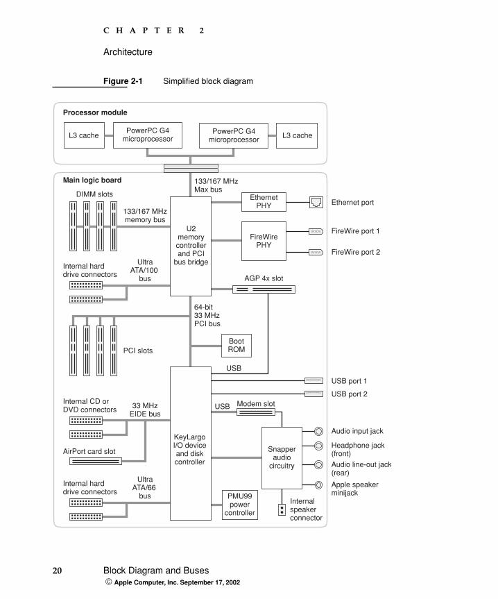
Figure 2-1 is a simplified block diagram of the Power Mac G4 computer. The diagram shows the main ICs and the buses that connect them together.
The architecture of the Power Mac G4 is based on the PowerPC G4 microprocessor and two custom ICs: the U2 memory controller and bus bridge, and the KeyLargo I/O controller.
20 Block Diagram and Buses Apple Computer, Inc. September 17, 2002
C H A P T E R 2
Architecture
Figure 2-1 Simplified block diagram
Ethernet portEthernet
PHY133/167 MHzmemory bus
133/167 MHzMax bus
Audio line-out jack(rear)
Apple speakerminijack
FireWire port 1
64-bit33 MHzPCI bus
AGP 4x slot
PCI slots
PMU99power
controller
BootROM
Modem slot
USB port 1
USB
USB
USB port 2
DIMM slots
Internal harddrive connectors
FireWire port 2
Main logic board
33 MHzEIDE bus
UltraATA/66
bus
Internal harddrive connectors
Internal CD orDVD connectors
UltraATA/100
bus
Internalspeakerconnector
AirPort card slot
U2memorycontrollerand PCI
bus bridge
KeyLargoI/O deviceand diskcontroller
Headphone jack(front)
Audio input jack
FireWirePHY
Snapperaudio
circuitry
L3 cache
Processor module
PowerPC G4microprocessor
PowerPC G4microprocessor L3 cache
C H A P T E R 2
Architecture
Processor Module 21 Apple Computer, Inc. September 17, 2002
The Power Mac G4 has the following data buses, not counting the processor’s dedicated interface to the backside cache.
Processor bus: 133/167 MHz, 64-bit bus connecting the processor module to the U2 IC
Memory bus: 133/167 MHz, 64-bit bus connecting the main memory to the U2 IC
AGP-4x bus: 66 MHz, 32-bit bus connecting the AGP graphics card to the U2 IC
PCI bus: 33 MHz, 64-bit bus connecting the KeyLargo I/O controller, the boot ROM, and the PCI slots to the U2 IC
Ultra ATA/100 and ATA/66 buses: supports internal hard drive connectors
EIDE bus: 33 MHz supports internal CD and DVD drive connectors and the AirPort card connector
The remainder of this chapter describes the architecture in three sections centered around the processor module, the U2 memory controller and bridge IC, and the KeyLargo I/O controller IC.
Processor Module
The processor module is a separate logic board that contains two G4 microprocessors and their external memory caches.
The processor module is connected to the main logic board by a 300-pin connector. To achieve the required level of performance, the signal lines that connect the processor module and the main logic board are carefully matched in length, loading, and impedance.
PowerPC G4 MicroprocessorThe PowerPC G4 microprocessors used in the Power Mac G4 computer have many powerful features, including a pipelined system bus called MaxBus.
The PowerPC G4 used in the Power Mac G4 computer has the following features:
22 Processor Module Apple Computer, Inc. September 17, 2002
C H A P T E R 2
Architecture
32-bit PowerPC implementation
superscalar PowerPC core
Velocity Engine (AltiVec technology): 128-bit-wide vector execution unit
high bandwidth MaxBus with 36 address bits and 64 data bits
fully symmetric multiprocessing capability
dual 32 KB instruction and data caches (level 1)
built-in 256 KB backside L2 cache
support for up to 2 MB backside L3 cache
on-chip L3 tag storage
For more information, see the reference at “PowerPC G4 Microprocessor” (page 65).
Cache MemoryIn addition to the 256 KB level 2 (L2) cache built into the PowerPC G4 microprocessor, the processor module also has an external level 3 (L3) cache for each microprocessor. The L3 cache consists of 1 or 2 MB of double data rate (DDR) SSRAM. The clock frequency and clock ratio for the L3 cache are shown below.
Dual ProcessorsThe Power Mac G4 computer contains two PowerPC G4 processors, each with its own external L3 cache. The dual-processor configuration allows applications that support multitasking to approximately double their performance.
Clock Frequency (MHz) Clock Ratio
867 MHz uP 216.66 4:1
1 GHz uP 250 4:1
1.25 GHz uP 250 5:1
C H A P T E R 2
Architecture
U2 Bridge and Memory Controller 23 Apple Computer, Inc. September 17, 2002
U2 Bridge and Memory Controller
The U2 custom IC is at the heart of the Power Mac G4 computer. It provides the bridging functionality between the processors, the memory system, the PCI-based I/O system, the AGP slot, and the FireWire and Ethernet interfaces. It also provides the Ultra ATA/100 disk drive interface.
Processor BusThe processor bus is a 133 or 167 MHz bus connecting the processor module to the U2 IC. The bus has 64-bit wide data and 32-bit wide addresses. The bus uses MaxBus protocols, supported by the U2 IC.
The MaxBus protocol includes enhancements that improve bus efficiency and throughput over the 60x bus. The enhancements include
out-of-order completion
address bus streaming
intervention
Out-of-order completion allows the memory controller to optimize the data bus efficiency by transferring whichever data is ready, rather than having to pass data across the bus in the order the transactions were posted on the bus. This means that a fast DDR SDRAM read can pass a slow PCI read, potentially enabling the processor to do more before it has to wait on the PCI data.
Address-bus streaming allows a single master on the bus to issue multiple address transactions back-to-back. This means that a single master can post addresses at the rate of one every two clocks, rather than one every three clocks, as it is in the 60x bus protocol.
Intervention is a cache-coherency optimization that improves performance for dual-processor systems. If one processor modifies some data, that data first gets stored only in that processor’s cache. If the other processor then wants that data, it needs to get the new modified values. In previous systems, the first processor must
24 U2 Bridge and Memory Controller Apple Computer, Inc. September 17, 2002
C H A P T E R 2
Architecture
write the modified data to memory and then the second processor can read the correct values from memory. With intervention, the first processor sends the data directly to the second processor, reducing latency by a factor of ten or more.
Main Memory BusFor the 867 MHz Power Mac G4, the main memory bus connects the main memory to the U2 IC via a 133 MHz, 64-bit data bus. For the 1 GHz or 1.25 GHz Power Mac G4, the main memory bus connects the main memory to the U2 IC via a 167 MHz, 64-bit data bus. For the 867 MHz computer, the minimum speed DDR is 2x133 MHz, which is DDR 266 (PC2100). For the 1 GHz and 1.25 GHz computers, the minimum speed DDR is 2x167 MHz, which is DDR 333 (PC2700).
Main memory is provided by up to four 133 MHz DDR 266 or 167 MHz DDR 333 DIMMs using double data rate SDRAM devices. Supported DIMM sizes are 256 and 512 MB (also is 128 MB- and 1GB-capable). The memory slots accept four 512-MB DIMMs (also is capable of 2-1GB) for a maximum memory size of 2 GB. For more information about memory DIMMs, see “RAM Expansion” (page 59).
The address bus is connected to all four DIMM slots, so the total number of address bus loads to the controller IC can vary from one to eight. The data bus is connected through four switches, one for each DIMM slot. Only one switch is selected at a time, so the data bus presents either one or two loads, depending on whether the selected DIMM has one or two banks. The data switches have no drive capability; they are either low or high impedance, depending on whether they are selected or not.
Ultra ATA/100 InterfaceThe U2 IC implements a single Ultra ATA/100 hard disk interface and can accommodate one or two internal hard drives. In the absence of a SCSI card, this interface can be used as the boot drive.
For information about the drive bays, see “Fixed-Media Drives” (page 43).
The KeyLargo IC provides DB-DMA (descriptor-based direct memory access) support for the Ultra ATA/66 interface.
C H A P T E R 2
Architecture
U2 Bridge and Memory Controller 25 Apple Computer, Inc. September 17, 2002
Accelerated Graphics Port BusThe accelerated graphics port (AGP) bus is a 66 MHz, 32-bit bus connecting the AGP card to the U2 IC. Data is transmitted at both edges of the clock and appears at a rate 4x the clock. The bus is an AGP-4x bus with twice the performance of the AGP-2x bus, supporting peak transfers of 512 MB/s.
The AGP bus is a superset of the PCI bus, with the addition of separate address lines so it does not multiplex address and data when running in AGP mode. Having a separate address bus allows the AGP bus to pipeline addresses, thereby improving performance.
To further improve the performance of the AGP bus, the U2 IC supports a graphics address remapping table (GART). Because the virtual memory system organizes main memory as randomly distributed 4 KB pages, DMA transactions for more than 4 KB of data must perform scatter-gather operations. To avoid this necessity for AGP transactions, the GART is used by the AGP bridge in the U2 to translate a linear address space for AGP transactions into physical addresses in main memory.
For more information on the graphics cards installed in the AGP slot, refer to “Graphics Cards” (page 31).
PCI BusThe 33-MHz, 64-bit PCI bus connects the U2 IC to the boot ROM, the KeyLargo I/O controller, and the PCI slots. The U2 IC used in the Power Mac G4 computer supports the PCI write combining feature. This feature allows sequential write transactions involving the Memory Write or Memory Write and Invalidate commands to be combined into a single PCI transaction. The memory write transactions being combined must be to sequential, ascending, and non-overlapping PCI addresses. Placing an eieio or sync command between the write commands prevents any write combining.
For more information on the PCI bus, refer to “PCI Expansion Slots” (page 62).
Note: The AGP bus is 1.5 V only and is not backward compatible. Older AGP cards will not work in the Power Mac G4.
26 U2 Bridge and Memory Controller Apple Computer, Inc. September 17, 2002
C H A P T E R 2
Architecture
Boot ROMThe boot ROM consists of 1 MB of on-board flash EPROM. The boot ROM includes the hardware-specific code and tables needed to start up the computer using Open Firmware, to load an operating system, and to provide common hardware access services.
Ethernet Controller The U2 IC includes an Ethernet media access controller (MAC). As a separate I/O channel on the U2 IC, it can operate at its full capacity without degrading the performance of other peripheral devices. The U2 IC provides DMA support for the Ethernet interface.
The MAC implements the link layer. It is connected to a PHY interface IC that provides 10-BaseT, 100-BaseT, or 1000-BaseT operation over a standard twisted-pair interface. The Ethernet port is auto-sensing and self-configuring to allow use of either a cross-over or straight-through cable. The operating speed of the link is automatically negotiated by the PHY and the bridge or router to which the Ethernet port is connected. For information about the port, see “Ethernet Port” (page 39).
FireWire ControllersThe U2 IC includes an IEEE 1394 FireWire controller that implements the FireWire link layer and supports transfer rates of 100, 200, and 400 Mbps. The PHY is powered as long as the computer is connected to AC power. While operating, the PHY acts as a repeater so that the FireWire bus remains connected. For more information, see “FireWire Ports” (page 36).
C H A P T E R 2
Architecture
KeyLargo I/O Controller 27 Apple Computer, Inc. September 17, 2002
KeyLargo I/O Controller
The KeyLargo custom IC is the third major component of the architecture. It provides all the I/O functions except Ethernet and FireWire. The KeyLargo IC provides two USB root hubs, an Ultra ATA/66 (ATA-66 UDMA Mode 4 and Multiword DMA Mode 4), an EIDE interface, and support for the communication slot and the sound IC.
DMA SupportThe KeyLargo IC provides DB-DMA (descriptor-based direct memory access) support for the following I/O channels:
Ultra ATA/66
EIDE interface
Communication slot interface
IIS channel to the sound subsystem
The DB-DMA system provides a scatter-gather process based on memory-resident data structures that describe the data transfers. The DMA engine is enhanced to allow bursting of data files for improved performance.
Interrupt SupportThe interrupt controller for the Power Mac G4 system is an MPIC cell in the KeyLargo IC. In addition to accepting all the KeyLargo internal interrupt sources, the MPIC controller accepts external interrupts from dedicated interrupt pins and serial interrupts from the U2 serial interrupt stream. The signals from the U2 IC are synchronized to the operation of the MPIC circuitry, so there is no additional interrupt latency on the U2 interrupts.
28 KeyLargo I/O Controller Apple Computer, Inc. September 17, 2002
C H A P T E R 2
Architecture
USB InterfaceThe KeyLargo IC implements two independent USB root hubs, each of which is connected to one of the ports on the back panel of the computer. The use of two independent hubs allows both USB ports to support high data rate devices at the same time with no degradation of their performance. If a user connects a high-speed device to one port and another high-speed device to the other, both devices can operate at their full data rates.
The two external USB connectors support USB devices with data transfer rates of 1.5 Mbps or 12 Mbps. For more information, see “USB Ports” (page 33).
Internally, the second port of one controller is routed to the USB signal pair on the AGP slot. The second port of the other controller is routed to the modem slot for an internal USB modem.
The USB ports comply with the Universal Serial Bus Specification 1.1 Final Draft Revision. The USB register set complies with the Open Host Controller Interface (OHCI) specification.
Ultra ATA/66 InterfaceThe KeyLargo IC implements a single Ultra ATA/66 hard disk interface. This interface can accommodate one or two internal hard drives. The KeyLargo IC provides DB-DMA (descriptor-based direct memory access) support for the Ultra ATA/66 interface.
For information about the drive bays, see “Fixed-Media Drives” (page 43).
Enhanced IDE Interface In the Power Mac G4, the KeyLargo IC provides an enhanced IDE (EIDE) interface. The EIDE interface supports the removable media drives mounted behind the front panel, an optical drive, and second optical drive. The EIDE data bus is shared with the AirPort wireless LAN port.
For information about specific drives, see “Removable-Media Drives” (page 41).
The KeyLargo IC provides DB-DMA (descriptor-based direct memory access) support for the EIDE interface.
C H A P T E R 2
Architecture
KeyLargo I/O Controller 29 Apple Computer, Inc. September 17, 2002
Wireless LAN ModuleThe interface between the AirPort wireless LAN module and the KeyLargo IC is similar to a PC Card interface.
The AirPort Card wireless LAN module contains a media access controller (MAC), a digital signal processor (DSP), and a radio-frequency (RF) section. The module has a connector for the cable to the antennas, which are built into the computer’s case. The AirPort port shares the EIDE data bus.
The wireless LAN module is based on the IEEE 802.11 standard. The wireless LAN module transmits and receives data at up to 11 Mbps and is compatible with older systems that operate at 1 or 2 Mbps. For information about its operation, see “AirPort Card” (page 45).
Modem Slot Support The KeyLargo IC has a traditional Macintosh serial port and a USB port, which are connected to the modem slot. The Power Mac G4 implements the USB port for modem support. The KeyLargo IC also provides digital audio to the slot in the form of an IIS port that shares pins with the serial port.
The KeyLargo IC provides DB-DMA (descriptor-based direct memory access) support for the modem slot interface.
The internal hardware modem is a separate module that contains a modem controller IC, a data pump, and the interface to the telephone line (DAA). For more information about the modem, see “Internal Modem” (page 44).
Sound Circuitry The sound circuitry, called Snapper, is connected to the KeyLargo IC by a standard IIS (inter-IC sound) bus. The KeyLargo IC provides DB-DMA (descriptor-based direct memory access) support for the IIS port.
The core of the Snapper circuitry is an IC that performs digital audio processing and codec functions. The digital audio processing functions include output equalization, dynamic range compression, and volume control. The equalization
30 KeyLargo I/O Controller Apple Computer, Inc. September 17, 2002
C H A P T E R 2
Architecture
and dynamic range control functions are set to fixed values to equalize a set of Apple Pro Speakers. Those functions are bypassed for signals sent to the audio output jack.
The codec functions include one stereo input pair and three stereo output pairs.
Stereo signals from the audio input jack are routed to an analog line input buffer that drives the internal A/D converter.
Digital audio data from the KeyLargo IC drives the internal D/A converter. Analog audio signals from the D/A converter are routed to the headphone jack, the line output jack, and an audio power amplifier.
The audio power amplifier drives the internal speaker, the Apple Pro Speakers, and front headphone. When Apple Pro Speakers are connected to the external speaker jack or headphones are installed, the internal speaker is muted.
For a description of the features of the sound system, see “Sound System” (page 50).
Power ControllerThe power management controller in the Power Mac G4 is a microcontroller called the PMU99. It supports new modes of power management that provide significantly lower power consumption than previous systems. For more information, see “Power-Saving Modes” (page 17).
C H A P T E R 2
Architecture
Graphics Cards 31 Apple Computer, Inc. September 17, 2002
Graphics Cards
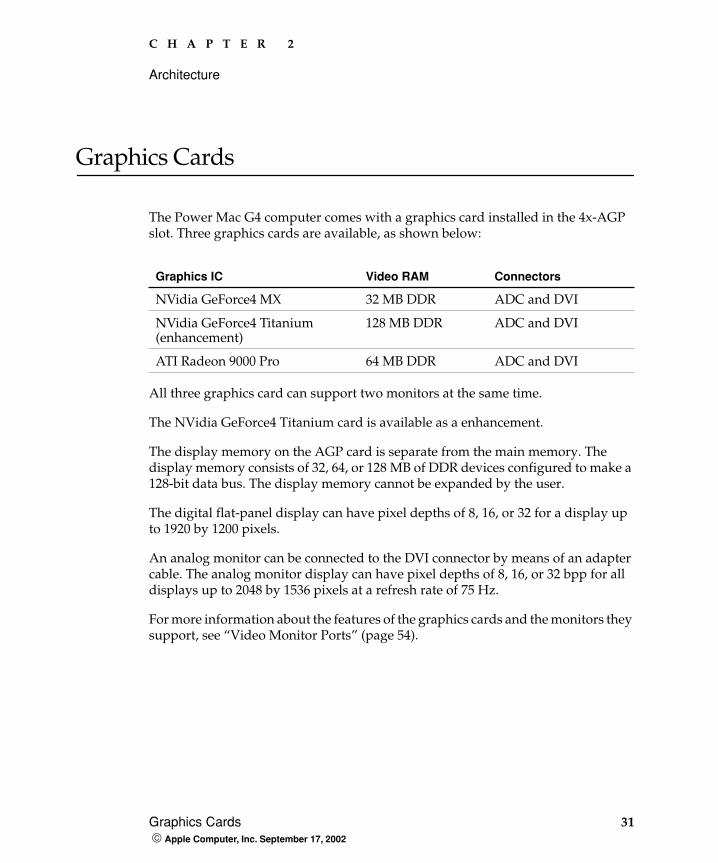
The Power Mac G4 computer comes with a graphics card installed in the 4x-AGP slot. Three graphics cards are available, as shown below:
All three graphics card can support two monitors at the same time.
The NVidia GeForce4 Titanium card is available as a enhancement.
The display memory on the AGP card is separate from the main memory. The display memory consists of 32, 64, or 128 MB of DDR devices configured to make a 128-bit data bus. The display memory cannot be expanded by the user.
The digital flat-panel display can have pixel depths of 8, 16, or 32 for a display up to 1920 by 1200 pixels.
An analog monitor can be connected to the DVI connector by means of an adapter cable. The analog monitor display can have pixel depths of 8, 16, or 32 bpp for all displays up to 2048 by 1536 pixels at a refresh rate of 75 Hz.
For more information about the features of the graphics cards and the monitors they support, see “Video Monitor Ports” (page 54).
Graphics IC Video RAM Connectors
NVidia GeForce4 MX 32 MB DDR ADC and DVI
NVidia GeForce4 Titanium (enhancement)
128 MB DDR ADC and DVI
ATI Radeon 9000 Pro 64 MB DDR ADC and DVI

32 Graphics Cards Apple Computer, Inc. September 17, 2002
C H A P T E R 2
Architecture
USB Ports 33 Apple Computer, Inc. September 17, 2002
C H A P T E R 3
3 Input and Output Devices
This chapter describes the Power Mac G4 computer’s built-in I/O devices and the ports for connecting external I/O devices. Each of the following sections describes an I/O port or device.
USB Ports
The Power Mac G4 computer has two external Universal Serial Bus (USB) ports on the back. The USB ports are used for connecting the keyboard and mouse as well as additional I/O devices such as printers, scanners, and low-speed storage devices.
Each USB port is connected to a separate USB root hub, allowing both USB ports to support 12 Mbps devices at the same time with no degradation of their performance. (USB port 2 is shared internally with the USB signals to the ADC monitor.)
The USB ports comply with the Universal Serial Bus Specification 1.1 Final Draft Revision. The USB register set complies with the Open Host Controller Interface (OHCI) specification.
For more information about USB on Macintosh computers, please refer to Apple Computer’s Mac OS USB DDK API Reference and the other sources listed in “USB Interface” (page 71).
34 USB Ports Apple Computer, Inc. September 17, 2002
C H A P T E R 3
Input and Output Devices
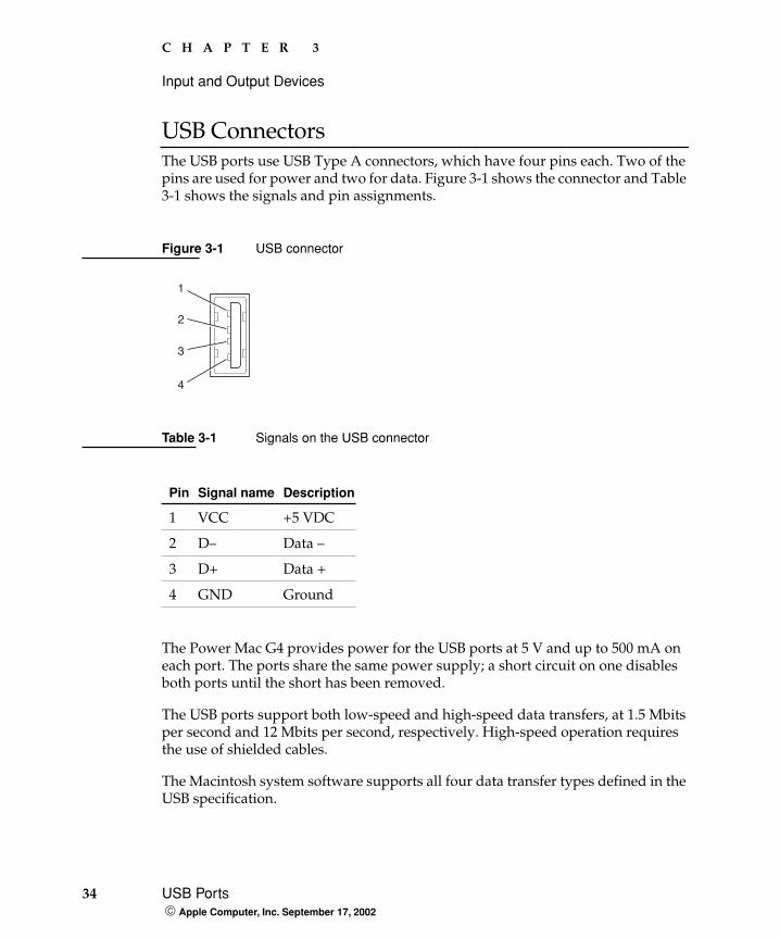
USB ConnectorsThe USB ports use USB Type A connectors, which have four pins each. Two of the pins are used for power and two for data. Figure 3-1 shows the connector and Table 3-1 shows the signals and pin assignments.
Figure 3-1 USB connector
The Power Mac G4 provides power for the USB ports at 5 V and up to 500 mA on each port. The ports share the same power supply; a short circuit on one disables both ports until the short has been removed.
The USB ports support both low-speed and high-speed data transfers, at 1.5 Mbits per second and 12 Mbits per second, respectively. High-speed operation requires the use of shielded cables.
The Macintosh system software supports all four data transfer types defined in the USB specification.
Table 3-1 Signals on the USB connector
Pin Signal name Description
1 VCC +5 VDC
2 D– Data –
3 D+ Data +
4 GND Ground
1
3
2
4
C H A P T E R 3
Input and Output Devices
USB Ports 35 Apple Computer, Inc. September 17, 2002
Waking Up From Sleep USB devices can provide a remote wakeup function for the computer. The USB root hub in the computer is set to support remote wakeup whenever a device is attached to the bus. The device wakes the computer by sending a Resume event to the USB root hub. The mouse and keyboard that come with the computer use this method to wake the computer on a key press or mouse click.
This functionality is part of the USB-suspend mode defined in the USB specification. Information about the operation of USB-suspend mode on Macintosh computers is included in Mac OS USB DDK API Reference , available on the World Wide Web at the following.
For Mac OS X:
http://developer.apple.com/hardware/usb/downloadsdk.htm
and refer to the USBSuspendDevice section.
For Mac OS 9: http://developer.apple.com/techpubs/hardware/DeviceManagers/usb/usb.html
Booting From USB Storage Devices The Power Mac G4 can boot from a USB storage device that follows the USB Mass Storage Class specification.
Class drivers are software components that are able to communicate with many USB devices of a particular kind. If the appropriate class driver is present, any number of compliant devices can be plugged in and start working immediately without the need to install additional software. The Mac OS for the Power Mac G4 computer includes a class driver that supports devices that meet the USB Mass Storage Class specification.
36 FireWire Ports Apple Computer, Inc. September 17, 2002
C H A P T E R 3
Input and Output Devices
FireWire Ports
The Power Mac G4 computer has two external FireWire ports on the rear panel of the enclosure. The FireWire ports have 6-pin connectors and support transfer rates of 100, 200, and 400 Mbps (megabits per second).
The FireWire ports:
provide 15 watts of power when the computer system is on or asleep
support up to 62 devices
provide bus repeating capability as long as the computer is connected to AC power
The FireWire hardware and software provided with the Power Mac G4 are capable of all asynchronous and isochronous transfers defined by the IEEE 1394 standard.
Developers of FireWire peripherals are required to provide device drivers. A driver for DV (digital video) is included in QuickTime 4.0 and later versions.
For more information about FireWire on Macintosh computers, please refer to the Apple FireWire website and the other sources listed in “FireWire Interface” (page 71).
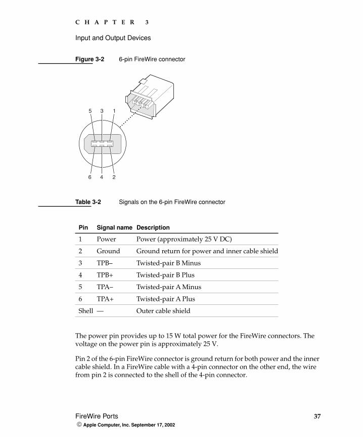
6-Pin FireWire ConnectorFireWire ports 1 and 2 use the six-pin connectors shown in Figure 3-2. The connector signals and pin assignments are shown in Table 3-2.
Note: FireWire cables are not included with this product and must be purchased independently, if required.
C H A P T E R 3
Input and Output Devices
FireWire Ports 37 Apple Computer, Inc. September 17, 2002
Figure 3-2 6-pin FireWire connector
The power pin provides up to 15 W total power for the FireWire connectors. The voltage on the power pin is approximately 25 V.
Pin 2 of the 6-pin FireWire connector is ground return for both power and the inner cable shield. In a FireWire cable with a 4-pin connector on the other end, the wire from pin 2 is connected to the shell of the 4-pin connector.
Table 3-2 Signals on the 6-pin FireWire connector
Pin Signal name Description
1 Power Power (approximately 25 V DC)
2 Ground Ground return for power and inner cable shield
3 TPB– Twisted-pair B Minus
4 TPB+ Twisted-pair B Plus
5 TPA– Twisted-pair A Minus
6 TPA+ Twisted-pair A Plus
Shell — Outer cable shield
135
246
38 FireWire Ports Apple Computer, Inc. September 17, 2002
C H A P T E R 3
Input and Output Devices
The signal pairs are crossed in the cable itself so that pins 5 and 6 at one end of the cable connect with pins 3 and 4 at the other end. When transmitting, pins 3 and 4 carry data and pins 5 and 6 carry clock; when receiving, the reverse is true.
Booting from a FireWire DeviceThe Power Mac G4 can boot from a FireWire storage device that implements SBP-2 (Serial Bus Protocol) with the RBC (reduced block commands) command set. Detailed information is available from Developer Technical Support at [email protected].
For additional information about the FireWire interface and the Apple API for FireWire device control, see the references shown in “FireWire Interface” (page 71).
Target Disk Mode The user has the option at boot time to put the computer into a mode of operation called Target Disk Mode (TDM). When the Power Mac G4 computer is in Target Disk Mode and connected to another Macintosh computer by a FireWire cable, the Power Mac G4 operates like a FireWire mass storage device with the SBP-2 (Serial Bus Protocol) standard. Target Disk Mode has two primary uses:
high-speed data transfer between computers
diagnosis and repair of a corrupted internal hard drive
The Power Mac G4 computer can operate in Target Disk Mode as long as the other computer has a FireWire port and either Mac OS X (any version) or Mac OS 9 with FireWire software version 2.3.3 or later.
To put the Power Mac G4 computer into Target Disk Mode, restart the computer and hold down the T key until the FireWire icon appears on the display. Then connect a FireWire cable from the Power Mac G4 to the other computer. When the other computer completes the FireWire connection, a hard disk icon appears on its desktop.
If you disconnect the FireWire cable or turn off the Power Mac G4 computer while in Target Disk Mode, an alert appears on the other computer.
C H A P T E R 3
Input and Output Devices
Ethernet Port 39 Apple Computer, Inc. September 17, 2002
To take the Power Mac G4 out of Target Disk Mode, drag the hard disk icon on the other computer to the trash, then press the power button on the Power Mac G4 computer.
For more information about Target Disk Mode, see the section “Target Mode” in Tech Note 1189, The Monster Disk Driver technical note. For information about obtaining the Tech Note, see “Apple Technical Notes” (page 65).
Ethernet Port
The Power Mac G4 computer has a built-in Ethernet port that supports 10Base-T, 100Base-T, and 1000Base-T transfer rates. In operation, the actual speed of the link is auto-negotiated between the computer’s PHY device and the hub, switch, or router to which it is connected. The Ethernet port is auto-sensing and self-configuring to allow connection via either a cross-over or straight-through cable.
Both CAT 5 unshielded twisted pair (UTP) and shielded twisted pair (STP) cables work with the Ethernet port. A STP cble is recommended for noisy environments or run of greater than 100 meters.
Note: When connecting a Power Mac G4 computer directly to another computer without using an Ethernet hub, a crossover cable is not required; circuits in the PHY detect the type of connection and switch the signal configuration as required.
40 Ethernet Port Apple Computer, Inc. September 17, 2002
C H A P T E R 3
Input and Output Devices
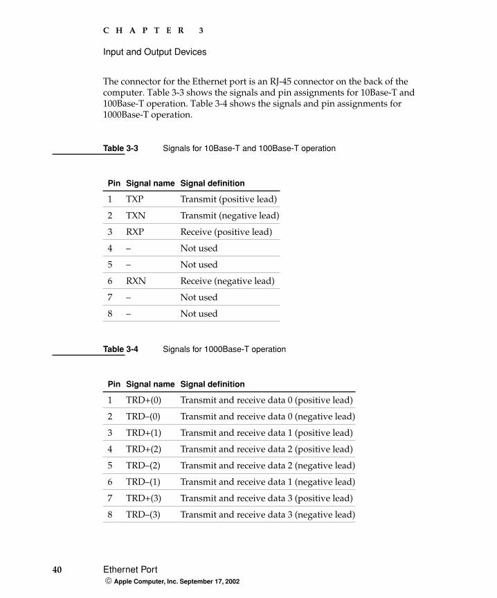
The connector for the Ethernet port is an RJ-45 connector on the back of the computer. Table 3-3 shows the signals and pin assignments for 10Base-T and 100Base-T operation. Table 3-4 shows the signals and pin assignments for 1000Base-T operation.
Table 3-3 Signals for 10Base-T and 100Base-T operation
Pin Signal name Signal definition
1 TXP Transmit (positive lead)
2 TXN Transmit (negative lead)
3 RXP Receive (positive lead)
4 – Not used
5 – Not used
6 RXN Receive (negative lead)
7 – Not used
8 – Not used
Table 3-4 Signals for 1000Base-T operation
Pin Signal name Signal definition
1 TRD+(0) Transmit and receive data 0 (positive lead)
2 TRD–(0) Transmit and receive data 0 (negative lead)
3 TRD+(1) Transmit and receive data 1 (positive lead)
4 TRD+(2) Transmit and receive data 2 (positive lead)
5 TRD–(2) Transmit and receive data 2 (negative lead)
6 TRD–(1) Transmit and receive data 1 (negative lead)
7 TRD+(3) Transmit and receive data 3 (positive lead)
8 TRD–(3) Transmit and receive data 3 (negative lead)
C H A P T E R 3
Input and Output Devices
Disk Drives 41 Apple Computer, Inc. September 17, 2002
To interconnect two computers for 1000Base-T operation, you must use 4-pair cable (Category 5 or 6).
The Ethernet interface in the Power Mac G4 computer conforms to the ISO/IEC 802.3 specification, where applicable, and complies with IEEE specifications 802.3i (10Base-T), 802.3u-1995 (100Base-T), and 802.3ab (1000Base-T).
Disk Drives
The Power Mac G4 computer has two bays for storage devices with removable-media access through the front panel and four bays for storage devices with fixed media. The removable media drives share the EIDE data bus with the AirPort wireless LAN port.
The Power Mac G4 computer supports ATA and ATAPI internal storage devices that are set for cable select mode, which force the devices to set their IDs based cable position. When transferring a drive to the Power Mac G4 from older computers, be sure to set the cable select on the drive. For additional information on cable select, refer to the following websites.
http://www.firmware.com/support/bios/cablesel.htm
http://www.seagate.com/support/kb/disc/faq/ata_cable_select.html
Removable-Media DrivesThe removable-media drives are connected by way of an EIDE (ATA-3) interface.
The two removable-media drives occupy both device locations on the IDE channel. The devices operate in an IDE Device 0/1 configuration. The upper optical drive is Device 0 (master), and the lower drive is Device 1 (slave). Power and data cables are provided for both bays, even if only one bay is occupied.
Note: Some non-Apple cables may not correctly support cable select mode.
Note: If two removable media drives are installed, press Option-Eject to eject the disk on the second drive.
42 Disk Drives Apple Computer, Inc. September 17, 2002
C H A P T E R 3
Input and Output Devices
The EIDE bus supports PIO Mode 4 and MultiWord DMA Mode 4 data transfers.
SuperDrive
Some configurations of the Power Mac G4 computer have a SuperDrive (combination DVD-R and CD-RW drive). The SuperDrive has a tray for loading the disc.
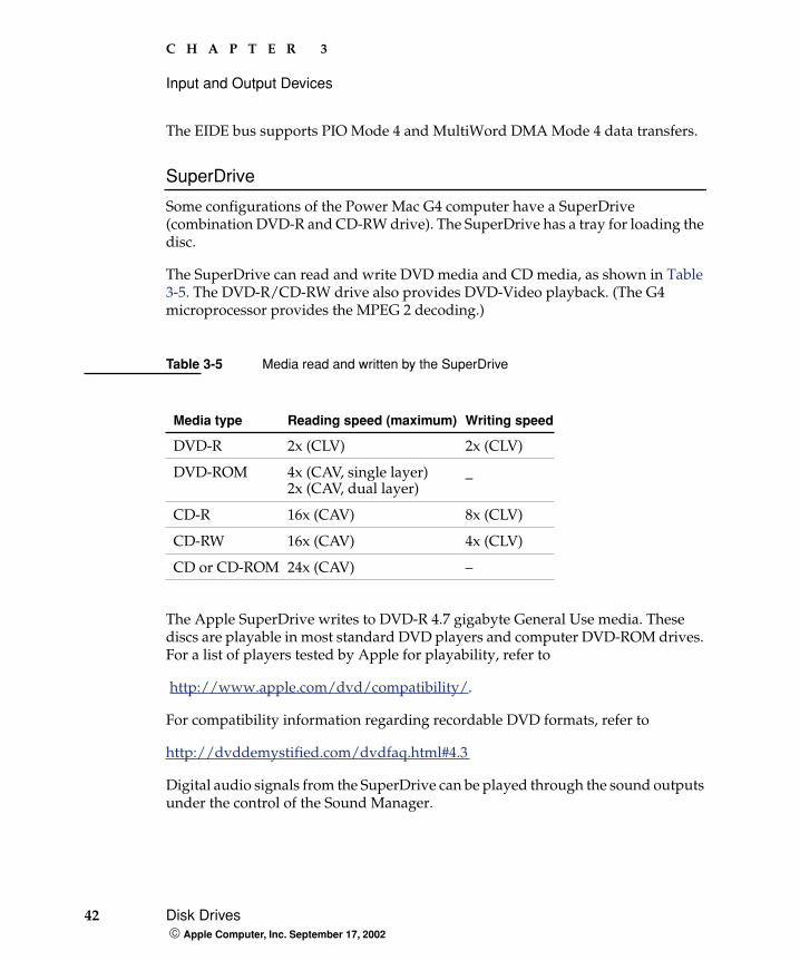
The SuperDrive can read and write DVD media and CD media, as shown in Table 3-5. The DVD-R/CD-RW drive also provides DVD-Video playback. (The G4 microprocessor provides the MPEG 2 decoding.)
The Apple SuperDrive writes to DVD-R 4.7 gigabyte General Use media. These discs are playable in most standard DVD players and computer DVD-ROM drives. For a list of players tested by Apple for playability, refer to
http://www.apple.com/dvd/compatibility/.
For compatibility information regarding recordable DVD formats, refer to
http://dvddemystified.com/dvdfaq.html#4.3
Digital audio signals from the SuperDrive can be played through the sound outputs under the control of the Sound Manager.
Table 3-5 Media read and written by the SuperDrive
Media type Reading speed (maximum) Writing speed
DVD-R 2x (CLV) 2x (CLV)
DVD-ROM 4x (CAV, single layer)2x (CAV, dual layer)
_
CD-R 16x (CAV) 8x (CLV)
CD-RW 16x (CAV) 4x (CLV)
CD or CD-ROM 24x (CAV) –
C H A P T E R 3
Input and Output Devices
Disk Drives 43 Apple Computer, Inc. September 17, 2002
The SuperDrive is an ATAPI drive and is cable-select enabled such that Device 0 master and Device 1 is slave.
Combo (DVD-ROM/CD-RW) Drive
A combination DVD-ROM and CD-RW drive is available as an option. The drive has a tray for loading the disc.
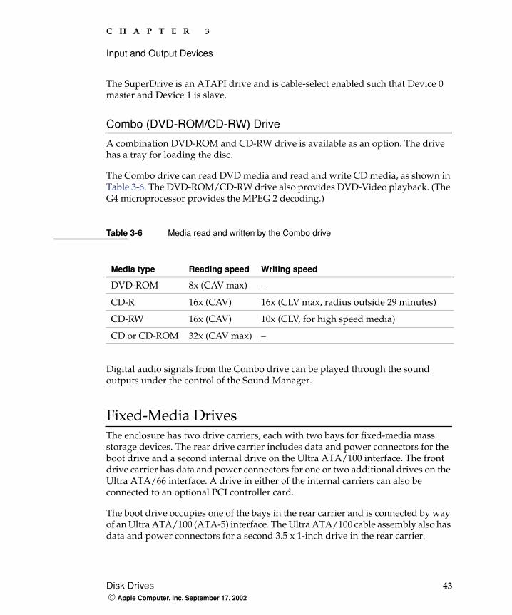
The Combo drive can read DVD media and read and write CD media, as shown in Table 3-6. The DVD-ROM/CD-RW drive also provides DVD-Video playback. (The G4 microprocessor provides the MPEG 2 decoding.)
Digital audio signals from the Combo drive can be played through the sound outputs under the control of the Sound Manager.
Fixed-Media DrivesThe enclosure has two drive carriers, each with two bays for fixed-media mass storage devices. The rear drive carrier includes data and power connectors for the boot drive and a second internal drive on the Ultra ATA/100 interface. The front drive carrier has data and power connectors for one or two additional drives on the Ultra ATA/66 interface. A drive in either of the internal carriers can also be connected to an optional PCI controller card.
The boot drive occupies one of the bays in the rear carrier and is connected by way of an Ultra ATA/100 (ATA-5) interface. The Ultra ATA/100 cable assembly also has data and power connectors for a second 3.5 x 1-inch drive in the rear carrier.
Table 3-6 Media read and written by the Combo drive
Media type Reading speed Writing speed
DVD-ROM 8x (CAV max) –
CD-R 16x (CAV) 16x (CLV max, radius outside 29 minutes)
CD-RW 16x (CAV) 10x (CLV, for high speed media)
CD or CD-ROM 32x (CAV max) –
44 Internal Modem Apple Computer, Inc. September 17, 2002
C H A P T E R 3
Input and Output Devices
The drives on the Ultra ATA/100 bus operate in a Device 0/1 configuration. The boot drive is cable-selected as Device 0 (master). An additional Ultra ATA/100 is configured as Device 1 (slave).
Like the drives on the Ultra ATA/100 bus, the drives on the Ultra ATA/66 bus operate in a Device 0/1 configuration. The Ultra ATA/66 bus supports PIO Mode 4, DMA Mode 2, and Ultra DMA Mode 4 data transfers.
Optional Ultra SCSI 160 Drive
An Ultra SCSI 160 drive and Ultra SCSI 160 PCI controller card are available as a configuration option for one to four drives. Installation of the SCSI drives in the bay are from front to back. The Ultra SCSI 160 is a low-voltage differential (LVD) interface and provides data transfer rates of up to 160 MB per second. The build-to-order SCSI card option includes cabling to connect up to four internal SCSI drives.
Internal Modem
The Power Mac G4 computer has an internal modem module. The external I/O connector for the modem is an RJ-11 connector installed on the rear panel of the computer. The modem has the following features:
modem bit rates up to 56 Kbps, supports K56flex modem standard and V.90 and V.92 for the Dash 2 modem
fax modem bit rates up to 14.4 Kbps
The modem appears to the system as a USB device that responds to the typical AT commands. The modem provides a sound output for monitoring the progress of the modem connection.
C H A P T E R 3
Input and Output Devices
AirPort Card 45 Apple Computer, Inc. September 17, 2002
AirPort Card
The Power Mac G4 computer supports the AirPort Card, an internal wireless LAN module. The AirPort Card is available as a build-to-order option or as a user-installable upgrade through the Apple Store.
By communicating wirelessly with a base station, the AirPort Card can be used for Internet access, email access, and file exchange. A base station provides the connection to the Internet or the bridge between the wireless signals and a wired LAN or both. The AirPort Base Station has connectors for a wired LAN, a DSL or cable modem, and a standard telephone line using its built-in 56 Kbps modem.
AirPort transmits and receives data at speeds up to 11 Mbps, comparable to wired networking speeds. Airport is Wi-Fi Certified, which means it is fully compatible with other devices that follow the IEEE 802.11b standard, including PCs. For more information about Wi-Fi and compatibility, see the reference at “Wireless Networks” (page 72).
Data SecurityAirPort has several features designed to maintain the security of the user’s data:
The system uses direct-sequence spread-spectrum (DSSS) technology that uses a multibit spreading code that effectively scrambles the data for any receiver that lacks the corresponding code.
The system can use an Access Control List of authentic network client ID values (wireless and MAC Addresses) to verify each client’s identity before granting access to the network.
When communicating with a base station, AirPort uses up to 128-bit encryption to encode data while it is in transit.
The AirPort Base Station can be configured to use NAT (Network Address Translation), protecting data from would-be Internet hackers.
46 AirPort Card Apple Computer, Inc. September 17, 2002
C H A P T E R 3
Input and Output Devices
The AirPort Base Station can authenticate users by their unique Ethernet IDs, preventing unauthorized computers from logging into a network. Network administrators can take advantage of RADIUS compatibility, used for authenticating users over a remote server. Smaller networks can offer the same security using a local look-up table located within the base station.
As an additional data security measure, VPN can be used in conjunction with the AirPort data security.
AirPort Hardware The AirPort Card is a wireless LAN module based on the IEEE 802.11 standard and using direct-sequence spread-spectrum (DSSS) technology. It is interoperable with PC-compatible wireless LANs that conform to the 802.11b standard and use DSSS.
Two AirPort antennas are built into the computer’s enclosure. One antenna is always used for transmitting. Either of the two antennas may be used for receiving. Using a diversity technique, the AirPort Card selects the antenna that gives the best reception.
The AirPort wireless LAN port shares the EIDE data bus with the removable-media devices.
AirPort Software Software that is provided with the AirPort Card includes
AirPort Setup Assistant, an easy-to-use program that guides the user through the steps necessary to set up the AirPort Card or set up an AirPort Base Station.
Users can switch between wireless networks and can create and join peer-to-peer networks. In Mac OS X, these functions are accessed via the AirPort- Menu-Extra pulldown. In Mac OS 9, these functions are available through the AirPort application.
AirPort Admin Utility, a utility for advanced users and system administrators. With it the user can edit the administrative and advanced settings needed for some advanced configurations.
C H A P T E R 3
Input and Output Devices
Keyboard 47 Apple Computer, Inc. September 17, 2002
Keyboard
The Power Mac G4 computer comes with a Apple Pro Keyboard. It is a full-size keyboard with function keys and separate keypad and editing sections.
The keyboard has an attached 1-meter cable and comes with a 1-meter extender cable for installations where the computer is located on the floor or away from the immediate desktop area.
Keyboard FeaturesHere is a list of the features of the Apple Pro Keyboard.
slope settable to either 0 or 6 degrees
108 keys (on the ANSI versions)
15 function keys
6 editing keys (Page Up, Page Down, Home, End, Forward Delete, and Help)
USB HID Consumer Page Usage multimedia control keys
full travel, standard pitch keys on alphanumeric, editing, and keypad sections, including function keys and cursor-position keys
localized worldwide: 33 versions, 3 standard layouts (ANSI, JIS, ISO)
LED indicators in the Caps Lock and Num Lock keys
USB hub functionality with two USB sockets
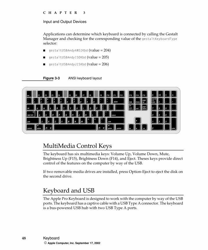
Keyboard LayoutThere are localized versions of the Apple Pro Keyboard for use in different parts of the world. The three standards used are ANSI (US and North America), JIS (Japan), and ISO (Europe). Figure 3-3 shows the keyboard layout for the ANSI keyboard.
Note: There is no power key on this keyboard.
48 Keyboard Apple Computer, Inc. September 17, 2002
C H A P T E R 3
Input and Output Devices
Applications can determine which keyboard is connected by calling the Gestalt Manager and checking for the corresponding value of the gestaltKeyboardType selector:
gestaltUSBAndyANSIKbd (value = 204)
gestaltUSBAndyISOKbd (value = 205)
gestaltUSBAndyJISKbd (value = 206)
Figure 3-3 ANSI keyboard layout
MultiMedia Control Keys The keyboard has six multimedia keys: Volume Up, Volume Down, Mute, Brightness Up (F15), Brightness Down (F14), and Eject. Theses keys provide direct control of the features on the computer by way of the USB.
If two removable media drives are installed, press Option-Eject to eject the disk on the second drive.
Keyboard and USBThe Apple Pro Keyboard is designed to work with the computer by way of the USB ports. The keyboard has a captive cable with a USB Type A connector. The keyboard is a bus-powered USB hub with two USB Type A ports.
]
return
shift
~
‘!1
@2
#3
$4
%5
^6
&7 8
(
9)
0 clear = /
7 8 9
4 5 6
1 2 3
.0 enter
esc F2 F3 F4F1
Q W E R T Y U I O P [
A S D F G H J K L ; ’
Z X C V B N M , . /
?><
":
delete
\tab
caps lock
shift
F9 F10 F11 F12 F13 F14 F15F6 F7 F8
control option
|
F5
numlock
option control
help homepageup
pagedown
del
altalt
end
C H A P T E R 3
Input and Output Devices
Mouse 49 Apple Computer, Inc. September 17, 2002
W A R N I N GA bus-powered hub as defined in the USB specification does not provide enough power to support a second bus-powered hub. A second bus-powered hub must be connected to the second USB port on the computer, not to a port on the keyboard.
Apple provides a HID class driver for the Apple Pro Keyboard, which supports the USB boot protocol. Other keyboards intended for use on the Macintosh platform must support the HID boot protocol, as defined in the USB Device Class Definition for Human Interface Devices (HIDs).
Programmer’s SwitchesKey combinations for programmer’s switches that used the Power button on earlier models now use the Eject key. Here are the key combinations for the Power Mac G4 computer.
Control-Command-Eject: restart immediately (reset)
Control-Command-Option-Eject: shut down immediately
Control-Eject: display the dialog for shutdown, restart, and sleep
Command-Eject: drop into MacsBug, if MacsBug is installed (Mac OS 9)
The key combinations are decoded in software and may not be available under some crashed conditions. Therefore, NMI and reset switches are also available on the front of the computer.
Mouse
The Power Mac G4 computer comes with an Apple Pro Mouse. The mouse case is made of polycarbonate plastic like the computer.
50 Sound System Apple Computer, Inc. September 17, 2002
C H A P T E R 3
Input and Output Devices
The Apple Pro Mouse is a new design that uses optical tracking in place of the traditional rolling ball. It works on almost any surface, though nonreflective, opaque surfaces without repetitive patterns work best. When running OS X, the new Apple Pro Mouse resolution is switched to 800dpi and the xy displacement data are signed 16-bit values.
Sound System
Under the control of the system software, the sound circuitry can create and record sounds digitally. It can receive audio signals through the audio input jack and send audio signals to the internal speaker, the headphone jack, the audio output jack, and the Apple speaker minijack.
Audio signals from the audio input jack are converted to digital data internally. All audio is handled digitally inside the computer, including audio data from the CD or DVD drive and from devices connected to the USB and FireWire ports. Audio data is converted to analog form for output to the internal speaker, the headphone jack, and the Apple Pro Speaker minijack.
The sound circuitry handles audio data as 44.1 kHz, 16-bit samples. If audio data sampled at a lower rate on another computer is played as output, the Sound Manager transparently upsamples the data to 44.1 kHz prior to sending the audio data to the sound circuitry.
Plugging-in some components in the sound system mutes other components, as shown below:
When Plug-In: This Is Muted:
External speakers Internal speakers
Rear line-out Internal and external speakers
Front headphone Internal and external speakers
Note: The rear line-out jack is never muted.
C H A P T E R 3
Input and Output Devices
Sound System 51 Apple Computer, Inc. September 17, 2002
Audio Input JackThe Power Mac G4 has a stereo audio line-in jack on the back panel. Low level consumer products operating below -10 dbu require a pre-amp.
The audio inputs are designed to accept high-level audio signals: 2 Vrms or +8 dbu, which is the standard output level from CD and DVD players. The output level of some consumer audio devices is lower, often 0.1 Vrms or –10 dbu. Sound recordings made on the Power Mac G4 with such low-level devices have more noise than those made with high-level devices. The user may obtain better results by connecting an amplifier between the low-level device and the computer’s audio input jack.
The audio input jack is a 3.5 mm miniature phone jack with the signals connected as follows:
The sound input jack has the following electrical characteristics:
maximum input signal amplitude 2 Vrms (5.65 Vpp), +8 dbu peak
input impedance at least 47 kilohms
channel separation greater than 60 dB
recommended source impedance 2 kilohms or less
ground noise rejection greater than 40 dB
frequency response 5 Hz to 20 kHz, +0.0, –0.5 dB
distortion below –80 dB
signal to noise ratio (SNR) greater than 90 dB (unweighted)
Tip Left-channel audio
Ring Right-channel audio
Sleeve Audio ground
52 Sound System Apple Computer, Inc. September 17, 2002
C H A P T E R 3
Input and Output Devices
Headphone Jack The Power Mac G4 has a stereo headphone jack on the front of the enclosure. The headphone jack is suitable for connecting a pair of headphones or amplified external speakers. When a plug is inserted into the headphone jack, the internal speaker and the Apple Pro Speakers (if connected) are muted.
The sound input jack is a 3.5 mm miniature phone jack with the signals connected as follows:
The headphone jack has the following electrical characteristics:
full-scale output level (open circuit) 1.5 Vrms (4.5 Vpp), +4 dbu peak
source impedance is 10 ohms
channel separation greater than 60 dB
recommended load impedance 32 ohms or greater
distortion, 32 ohm load, is better than –80 dB (0.5%)
frequency response, 32 ohm load, 20 Hz to 20 kHz, +0.0, –0.5 dB
signal-to-noise ratio (SNR) greater than 90 dB unweighted
Audio Output Jack The Power Mac G4 has a stereo output jack on the back of the enclosure. The audio output jack is suitable for connecting amplified external speakers.
Tip Left-channel audio
Ring Right-channel audio
Sleeve Audio ground
Note: Do not plug headphones into the rear line-out jack. Headphone impedance is 32 ohms and line-out impedance is 1 kilohm.
C H A P T E R 3
Input and Output Devices
Sound System 53 Apple Computer, Inc. September 17, 2002
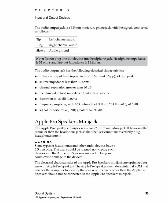
The audio output jack is a 3.5 mm miniature phone jack with the signals connected as follows:
The audio output jack has the following electrical characteristics:
full-scale output level (open circuit) 1.5 Vrms (4.5 Vpp), +4 dbu peak
source impedance less than 10 ohms
channel separation greater than 60 dB
recommended load impedance 1 kilohm or greater
distortion is –80 dB (0.02%)
frequency response, with 10 kilohms load, 5 Hz to 20 kHz, +0.0, –0.5 dB
signal-to-noise ratio (SNR) greater than 90 dB
Apple Pro Speakers MinijackThe Apple Pro Speakers minijack is a stereo 2.5 mm miniature jack. It has a smaller diameter than the headphone jack so that the user cannot inadvertently plug headphones into it.
W A R N I N GSome types of headphones and other audio devices have a 2.5 mm plug. The user should be warned not to plug such devices into the Apple Pro Speakers minijack. Doing so could cause damage to the devices.
The electrical characteristics of the Apple Pro Speakers minijack are optimized for use with Apple Pro Speakers. The Apple Pro Speakers include an internal ROM that enables the computer to identify the speakers. Speakers other than the Apple Pro Speakers should not be connected to the Apple Pro Speakers minijack.
Tip Left-channel audio
Ring Right-channel audio
Sleeve Audio ground
Note: Do not plug line-out devices into headphone jack. Headphone impedance is 32 ohms and line-out impedance is 1 kilohm.
54 Video Monitor Ports Apple Computer, Inc. September 17, 2002
C H A P T E R 3
Input and Output Devices
Video Monitor Ports
Depending on the configuration, the Power Mac G4 computer comes with either an ATI or an NVidia graphics card installed. The main features of the graphics cards are as follows:
The NVidia GeForce4 Titanium 128 MB DDR, ADC/DVI graphics card is available as a enhancement.
All three graphics cards can support two monitors at the same time.
The following sections describe the video connectors on the graphics cards.
Apple Display ConnectorThe graphics cards have an Apple proprietary connector called the ADC (Apple display connector). The connector carries both digital and analog video signals as well as USB and control signals and power for an external monitor. Figure 3-4 shows the contact configuration; Table 3-7 and Table 3-8 list the signals and pin assignments.
The maximum current available from the 25 V supply for the external monitor is 4.0 A.
Graphics IC Video RAM Connectors
ATI Radeon 9000 Pro 64 MB DDR ADC and DVI
NVidia GeForce4 MX 32 MB DDR ADC and DVI
C H A P T E R 3
Input and Output Devices
Video Monitor Ports 55 Apple Computer, Inc. September 17, 2002
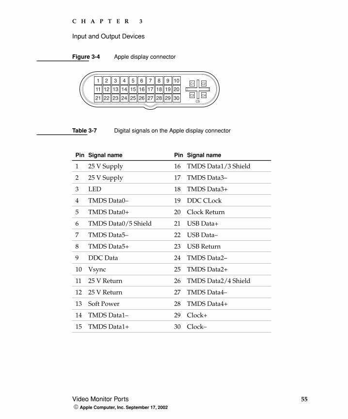
Figure 3-4 Apple display connector
Table 3-7 Digital signals on the Apple display connector
Pin Signal name Pin Signal name
1 25 V Supply 16 TMDS Data1/3 Shield
2 25 V Supply 17 TMDS Data3–
3 LED 18 TMDS Data3+
4 TMDS Data0– 19 DDC CLock
5 TMDS Data0+ 20 Clock Return
6 TMDS Data0/5 Shield 21 USB Data+
7 TMDS Data5– 22 USB Data–
8 TMDS Data5+ 23 USB Return
9 DDC Data 24 TMDS Data2–
10 Vsync 25 TMDS Data2+
11 25 V Return 26 TMDS Data2/4 Shield
12 25 V Return 27 TMDS Data4–
13 Soft Power 28 TMDS Data4+
14 TMDS Data1– 29 Clock+
15 TMDS Data1+ 30 Clock–
1 2 3 4 5 6 7 8
11 12 13 14 15 16 17 18
21 22 23 24 25 26 27 28
9 10
19 20
29 30C5
C3 C4
C1 C2
56 Video Monitor Ports Apple Computer, Inc. September 17, 2002
C H A P T E R 3
Input and Output Devices
The graphics data sent to the digital monitor use transition minimized differential signaling (TMDS). TMDS uses an encoding algorithm to convert bytes of graphics data into characters that are transition-minimized to reduce EMI with copper cables and DC-balanced for transmission over fiber optic cables. The TMDS algorithm also provides robust clock recovery for greater skew tolerance with longer cables or low-cost short cables. For additional information about TMDS, see the references shown in “Digital Visual Interface” (page 72).
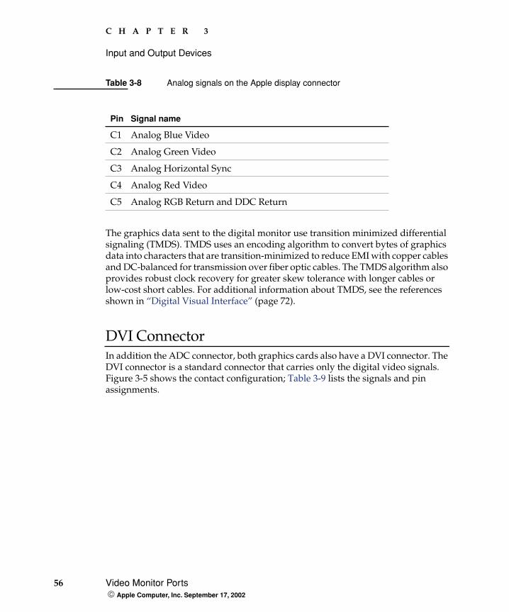
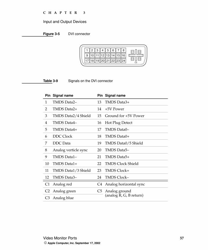
DVI ConnectorIn addition the ADC connector, both graphics cards also have a DVI connector. The DVI connector is a standard connector that carries only the digital video signals. Figure 3-5 shows the contact configuration; Table 3-9 lists the signals and pin assignments.
Table 3-8 Analog signals on the Apple display connector
Pin Signal name
C1 Analog Blue Video
C2 Analog Green Video
C3 Analog Horizontal Sync
C4 Analog Red Video
C5 Analog RGB Return and DDC Return
C H A P T E R 3
Input and Output Devices
Video Monitor Ports 57 Apple Computer, Inc. September 17, 2002
Figure 3-5 DVI connector
Table 3-9 Signals on the DVI connector
Pin Signal name Pin Signal name
1 TMDS Data2– 13 TMDS Data3+
2 TMDS Data2+ 14 +5V Power
3 TMDS Data2/4 Shield 15 Ground for +5V Power
4 TMDS Data4– 16 Hot Plug Detect
5 TMDS Data4+ 17 TMDS Data0–
6 DDC Clock 18 TMDS Data0+
7 DDC Data 19 TMDS Data0/5 Shield
8 Analog verticle sync 20 TMDS Data5–
9 TMDS Data1– 21 TMDS Data5+
10 TMDS Data1+ 22 TMDS Clock Shield
11 TMDS Data1/3 Shield 23 TMDS Clock+
12 TMDS Data3– 24 TMDS Clock–
C1 Analog red C4 Analog horizontal sync
C2 Analog green C5 Analog ground(analog R, G, B return)
C3 Analog blue
1 2 3 4 5 6 7 8
9 10 11 12 13 14 15 16
17 18 19 20 21 22 23 24C5
C3 C4
C1 C2
58 Video Monitor Ports Apple Computer, Inc. September 17, 2002
C H A P T E R 3
Input and Output Devices
The graphics data sent to the digital monitor use transition minimized differential signaling (TMDS). TMDS uses an encoding algorithm to convert bytes of graphics data into characters that are transition-minimized to reduce EMI with copper cables and DC balanced for transmission over fiber optic cables. The TMDS algorithm also provides robust clock recovery for greater skew tolerance with longer cables or low-cost short cables.
For information about TMDS, see the reference listed in “Digital Visual Interface” (page 72).
Note: The Power Mac G4 computer includes a DVI to VGA adapter.
RAM Expansion 59 Apple Computer, Inc. September 17, 2002
C H A P T E R 4
4 Expansion
This chapter describes the expansion features of the Power Mac G4 computer: the DDR SDRAM expansion slots and the PCI expansion slots.
RAM Expansion
The main logic board has four DDR SDRAM expansion slots for dual in-line memory modules (DIMMs). Each DIMM can contain 256 and 512 MB (also is 128 MB- and 1GB-capable) of double data rate synchronous dynamic RAM (DDR SDRAM). At least one of the RAM expansion slots contains a factory installed DIMM.
The DIMMs can be installed one or more at a time. The system supports linear memory organization; no performance gains are seen when two DIMMs of the same size are installed. Any supported size DIMM can be installed in any DIMM slot, and the combined memory of all of the DIMMs installed is configured as a contiguous array of memory.
The memory slots will accept four 512-MB DIMMs (also is capable of 2-1GB) for a maximum memory size of 2 GB.
For all microprocessor speeds and for both DDR226 and DDR333 SDRAM DIMMs, the Power Mac G4 supports CAS latencies of 2, 2.5, 3, 3.5, and 4.
60 RAM Expansion Apple Computer, Inc. September 17, 2002
C H A P T E R 4
Expansion
DIMM Specifications The RAM expansion slots accept 184-pin DDR SDRAM DIMMs that are 2.5 volt, unbuffered, 8-byte, nonparity, and DDR226-compliant (PC2100) or DDR333-compliant (PC2700).
ImportantDDR200 (PC1600) or slower DIMMs do not work in the Power Mac G4 computer.
ImportantDIMMs with any of the following features are not supported in the Power Mac G4 computer: registers or buffers, PLLs, ECC, parity, or EDO RAM.
Mechanical Specifications
The mechanical design of the DDR SDRAM DIMM is defined by the JEDEC specification JESD21-C, MODULES4_20_4, Release 11b. To find this specification on the World Wide Web, refer to “RAM Expansion Modules” (page 70).
The maximum height of DIMMs for use in the Power Mac G4 computer is 2 inches.
Electrical Specifications
The electrical design of the SDRAM DIMM is defined by the JEDEC specification JESD21-C, MODULES4_20_4, Release 11b. To find this specification on the World Wide Web, refer to “RAM Expansion Modules” (page 70).
The Serial Presence Detect (SPD) EEPROM specified in the JEDEC standard is required and must be set to properly define the DIMM configuration. The EEPROM is powered on 3.3 V. Details about the required values for each byte on the SPD EEPROM can be found on pages 68–70 of the JEDEC specification.
ImportantFor a DIMM to be recognized by the startup software, the SPD feature must be programmed properly to indicate the timing modes supported by the DIMM.
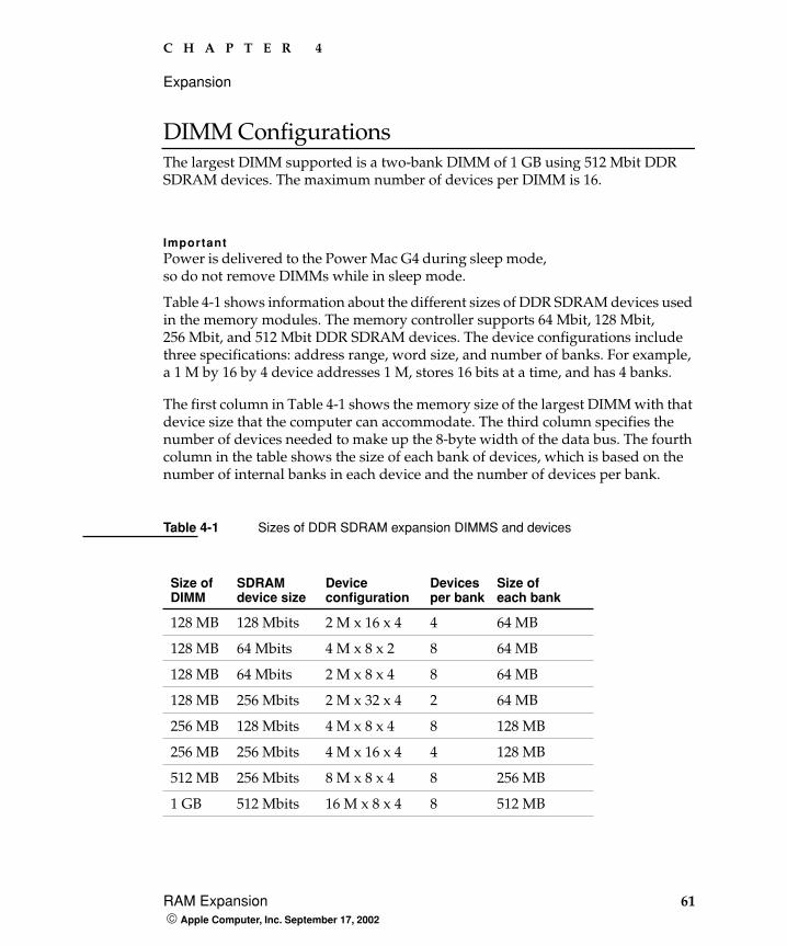
C H A P T E R 4
Expansion
RAM Expansion 61 Apple Computer, Inc. September 17, 2002
DIMM ConfigurationsThe largest DIMM supported is a two-bank DIMM of 1 GB using 512 Mbit DDR SDRAM devices. The maximum number of devices per DIMM is 16.
ImportantPower is delivered to the Power Mac G4 during sleep mode, so do not remove DIMMs while in sleep mode.
Table 4-1 shows information about the different sizes of DDR SDRAM devices used in the memory modules. The memory controller supports 64 Mbit, 128 Mbit, 256 Mbit, and 512 Mbit DDR SDRAM devices. The device configurations include three specifications: address range, word size, and number of banks. For example, a 1 M by 16 by 4 device addresses 1 M, stores 16 bits at a time, and has 4 banks.
The first column in Table 4-1 shows the memory size of the largest DIMM with that device size that the computer can accommodate. The third column specifies the number of devices needed to make up the 8-byte width of the data bus. The fourth column in the table shows the size of each bank of devices, which is based on the number of internal banks in each device and the number of devices per bank.
Table 4-1 Sizes of DDR SDRAM expansion DIMMS and devices
Size of DIMM
SDRAMdevice size
Device configuration
Devicesper bank
Size ofeach bank
128 MB 128 Mbits 2 M x 16 x 4 4 64 MB
128 MB 64 Mbits 4 M x 8 x 2 8 64 MB
128 MB 64 Mbits 2 M x 8 x 4 8 64 MB
128 MB 256 Mbits 2 M x 32 x 4 2 64 MB
256 MB 128 Mbits 4 M x 8 x 4 8 128 MB
256 MB 256 Mbits 4 M x 16 x 4 4 128 MB
512 MB 256 Mbits 8 M x 8 x 4 8 256 MB
1 GB 512 Mbits 16 M x 8 x 4 8 512 MB
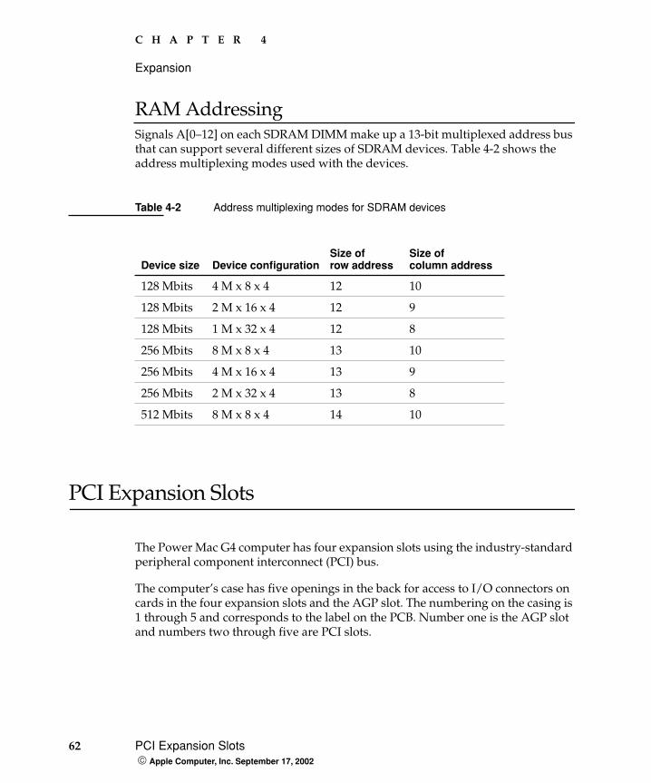
62 PCI Expansion Slots Apple Computer, Inc. September 17, 2002
C H A P T E R 4
Expansion
RAM AddressingSignals A[0–12] on each SDRAM DIMM make up a 13-bit multiplexed address bus that can support several different sizes of SDRAM devices. Table 4-2 shows the address multiplexing modes used with the devices.
PCI Expansion Slots
The Power Mac G4 computer has four expansion slots using the industry-standard peripheral component interconnect (PCI) bus.
The computer’s case has five openings in the back for access to I/O connectors on cards in the four expansion slots and the AGP slot. The numbering on the casing is 1 through 5 and corresponds to the label on the PCB. Number one is the AGP slot and numbers two through five are PCI slots.
Table 4-2 Address multiplexing modes for SDRAM devices
Device size Device configurationSize of row address
Size of column address
128 Mbits 4 M x 8 x 4 12 10
128 Mbits 2 M x 16 x 4 12 9
128 Mbits 1 M x 32 x 4 12 8
256 Mbits 8 M x 8 x 4 13 10
256 Mbits 4 M x 16 x 4 13 9
256 Mbits 2 M x 32 x 4 13 8
512 Mbits 8 M x 8 x 4 14 10
C H A P T E R 4
Expansion
PCI Expansion Slots 63 Apple Computer, Inc. September 17, 2002
The expansion slots accept 33 MHz PCI cards with either 32-bit or 64-bit address and data buses. The PCI cards can use power at +5 V, +3.3 V, or both. The slots accept standard 6.88-inch and 12.283-inch PCI cards as defined by the PCI Local Bus Specification, Revision 2.1. The cards are required to use the standard ISA fence described in the specification.
The expansion slots support all the required PCI signals and certain optional PCI signals. The PCI slots support the optional 64-bit bus extension signals and cache support signals.
The PCI slots and the AGP-4x slot carry the 3.3 V_AUX power and PME signals to allow an expansion card to wake the computer from sleep mode.
The maximum total power available for all four PCI slots and the AGP-4x slot is 80 watts. The AGP-4x slot can account for up to 30 watts of that total, depending on which card is installed.
To install or remove a PCI expansion card, the user first opens the door of the enclosure. Then the user removes the blank PCI fence for the appropriate slot, inserts the card in the slot, and screws the card’s fence into place to secure the card. The user then closes the enclosure door and turns on the computer. In order to use the new PCI card, a driver must be installed. The driver installation procedure is documented by the manufacturer of the PCI card.
ImportantBefore removing or installing PCI expansion cards, shut down the computer and unplug the AC power cord. The Power Mac G4 computer does not support PCI hot-plugging functionality. When the computer is powered-on or asleep, the main logic board has a red LED to warn that power is present.

64 PCI Expansion Slots Apple Computer, Inc. September 17, 2002
C H A P T E R 4
Expansion
Apple Technical Notes 65 Apple Computer, Inc. September 17, 2002
A P P E N D I X A
A Supplemental Reference Documents
For more information about the technologies mentioned in this developer note, you may wish to consult some of the references listed in the following sections.
For information about older models of Macintosh computers, refer to the developer notes archive at:
http://developer.apple.com/techpubs/hardware/hardware2.html
Apple Technical Notes
Apple Technical Notes answer many specific questions about the operation of Macintosh computers and the Mac OS. The notes are available on the Technical Note website at
http://developer.apple.com/technotes/
PowerPC G4 Microprocessor
Information about the PowerPC G4 microprocessor is available on the World Wide Web at
http://e-www.motorola.com/webapp/sps/site/taxonomy.jsp?nodeId=03M943030450467M98653
66 Velocity Engine (AltiVec) Apple Computer, Inc. September 17, 2002
A P P E N D I X A
Supplemental Reference Documents
Velocity Engine (AltiVec)
Velocity Engine is Apple’s name for the AltiVec vector processor in the PowerPC G4 microprocessor. Apple provides support for developers who are starting to use the Velocity Engine in their applications. Documentation, development tools, and sample code are available on the Apple website, at
http://developer.apple.com/hardware/ve/index.html
and
http://developer.apple.com/techpubs/macosx/CoreTechnologies/vDSP/vDSP.html
AltiVec Technology Programming Environments Manual (AltiVec PEM) is a reference guide for programmers. It contains a description for each instruction and information to help in understanding how the instruction works. You can obtain a copy of the AltiVec PEM through the Motorola documentation site on the World Wide Web, at
http://e-www.motorola.com/webapp/sps/site/overview.jsp?nodeId=03M943030450467M0ymK5Nf2
Multiprocessing Services
All configurations of the Power Mac G4 computer have dual microprocessors. The Multiprocessing Services API allows your OS9 application to create tasks that run independently on one or more processors. The Multiprocessing 2.1 SDK includes interfaces and libraries, documentation, demonstration applications, and sample code. You can download the SDK from Apple’s developer site on the World Wide Web at
http://developer.apple.com/macos/multiprocessing.html
A P P E N D I X A
Supplemental Reference Documents
3D Graphics 67 Apple Computer, Inc. September 17, 2002
3D Graphics
Developers of 3D graphics for games should know about OpenGL for Macintosh, a version of SGI’s application programming interface (API) and software library for 3D graphics.
Information is available on the World Wide Web at
http://www.apple.com/opengl
Developer support and documentation is available at
http://developer.apple.com/opengl/
Mac OS X
Mac OS X version 10.2 is installed by default on the Power Mac G4 computer. For access to Apple’s developer documentation for Mac OS X, see the Apple Developer Connection (ADC) website at
http://developer.apple.com/techpubs/macosx/macosx.html
and
http://developer.apple.com/techpubs/macosx/Carbon/oss/MultiPServices/multiprocessingservices.html
O'Reilly & Associates publishes a series of books about Mac OS X development. The books in this series have been technically reviewed by Apple engineers and are recommended by the Apple Developer Connection.
68 Mac OS 9.2.2 Apple Computer, Inc. September 17, 2002
A P P E N D I X A
Supplemental Reference Documents
Mac OS 9.2.2
Mac OS 9 is also included with the Power Mac G4 computer. Programming information about Mac OS 9 is available in technical bookstores and (for free download) on the World Wide Web at
http://developer.apple.com/techpubs/macosx/Carbon/carbon.html
You can find additional information in Apple Technical Notes at
http://developer.apple.com/technotes/
ROM-in-RAM Architecture
The system software in all current Macintosh computers uses a ROM-in-RAM approach, also called the NewWorld architecture. For more information about this architecture, see Technical Note 1167, NewWorld Architecture, available on Apple’s technical note website at
http://developer.apple.com/technotes/tn/tn1167.html
In OS 9, the memory in the ROM-in-RAM approach is not mapped one-to-one as it was for earlier PCI-based Macintosh computers. This could be a compatibility issue with some software. For more information see Technical Q&A DV 33, PrepareMemoryForIO for the New World, available on Apple’s Q&A website at
http://developer.apple.com/qa/dv/dv33.html
For OS X, refer to the various documents at
http://developer.apple.com/techpubs/macosx/Darwin/IOKit/iokit.html
A P P E N D I X A
Supplemental Reference Documents
Open Firmware 69 Apple Computer, Inc. September 17, 2002
Open Firmware
The software architecture implemented on current Macintosh computers follows the standard defined by the Open Firmware IEEE 1274-1994 specification. Three Technotes provide an introduction to Open Firmware on the Macintosh platform. They are
TN 1061: Open Firmware, Part I, available on the Technote web site at
http://developer.apple.com/technotes/tn/tn1061.html
TN 1062: Open Firmware, Part II, at
http://developer.apple.com/technotes/tn/tn1062.html
TN 1044: Open Firmware, Part III, at
http://developer.apple.com/technotes/tn/tn1044.html
Other Technotes provide additional information about Open Firmware on the Macintosh.
TN 2000: PCI Expansion ROMs and You, at
http://developer.apple.com/technotes/tn/tn2000.html
TN 2001: Running Files from a Hard Drive in Open Firmware, at
http://developer.apple.com/technotes/tn/tn2001.html
TN 2004: Debugging Open Firmware Using Telnet, at
http://developer.apple.com/technotes/tn/tn2004.html
70 RAM Expansion Modules Apple Computer, Inc. September 17, 2002
A P P E N D I X A
Supplemental Reference Documents
RAM Expansion Modules
The Power Mac G4 computer uses PC2100- or PC2700-compliant, 184-pin DDR SDRAM DIMMs.
The electrical and mechanical characteristics of the DIMM are given in JEDEC Standard 21-C. The specification can be found by using the search string JESD21-C on the Electronics Industry Association’s website at
http://www.jedec.org/DOWNLOAD/default.cfm
ATA Devices
ATA (AT Attachment), also referred to as integrated drive electronics (IDE), is a standard interface used with storage devices such as hard disk drives. For more information on ATA, refer to the following Apple website at
http://developer.apple.com/techpubs/hardware/DeviceManagers/ata/ata.html
ATA Manager 4.0 supports driver software for internal IDE drives and includes DMA support. For the latest information about ATA Manager 4.0, see Technical Note #1098, ATA Device Software Guide Additions and Corrections, available on the World Wide Web at
http://developer.apple.com/technotes/tn/tn1098.html
The web page for Technical Note #1098 includes a link to a downloadable copy of ATA Device Software Guide.
Information about the ATA standards is available at the Technical Committee T13 AT Attachment website, at
http://www.t13.org/
A P P E N D I X A
Supplemental Reference Documents
USB Interface 71 Apple Computer, Inc. September 17, 2002
USB Interface
For more information about USB on the Macintosh computer, refer to Apple Computer’s Mac OS USB DDK API Reference. Information is also available on the World Wide Web, at
http://developer.apple.com/techpubs/hardware/DeviceManagers/usb/usb.html
USB game controllers are supported by the InputSprocket component of the Apple Games Sprockets software architecture. InputSprocket software and information about the InputSprocket APIs can be found at
http://developer.apple.com/games/
For full specifications of the Universal Serial Bus, you should refer to the USB Implementation Forum on the World Wide Web, at
http://www.usb.org/developers/home.php3
FireWire Interface
For additional information about the FireWire IEEE 1394 interface and the Apple API for FireWire software, refer to the resources available on the Apple FireWire website at
http://developer.apple.com/hardware/FireWire/index.html
The IEEE 1394 standard is available from the IEEE; you can order that document electronically from the IEEE Standards Department website at
http://standards.ieee.org/
You may also find useful information at the 1394 trade association’s website at
http://www.1394ta.org/
72 Digital Visual Interface Apple Computer, Inc. September 17, 2002
A P P E N D I X A
Supplemental Reference Documents
Digital Visual Interface
For information about transition minimized differential signaling (TMDS) used with digital video monitors, see the specification, Digital Visual Interface DVI Revision 1.0, available on the website of the Digital Display Working Group (DDWG) at
http://www.ddwg.org/index.html
Wireless Networks
More information about Wi-Fi and wireless networks using the IEEE 802.11 standard is available on the website of the Wireless Ethernet Compatibility Alliance, at
http://www.wirelessethernet.org/OpenSection/index.asp
Typographical Conventions 73 Apple Computer, Inc. September 17, 2002
A P P E N D I X B
B Conventions and Abbreviations
This developer note uses the following typographical conventions and abbreviations.
Typographical Conventions
ImportantA note like this contains important information that you should read before proceeding.
W A R N I N GA note like this contains a warning about a situation that could cause a system crash or loss of data.
Abbreviations
When unusual abbreviations appear in this developer note, the corresponding terms are also spelled out. Standard units of measure and other widely used abbreviations are not spelled out.
Note: A note like this contains information that is of interest but is not essential for an understanding of the text.
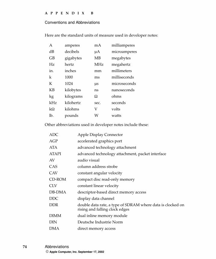
74 Abbreviations Apple Computer, Inc. September 17, 2002
A P P E N D I X B
Conventions and Abbreviations
Here are the standard units of measure used in developer notes:
Other abbreviations used in developer notes include these:
A amperes mA milliamperes
dB decibels µA microamperes
GB gigabytes MB megabytes
Hz hertz MHz megahertz
in. inches mm millimeters
k 1000 ms milliseconds
K 1024 µs microseconds
KB kilobytes ns nanoseconds
kg kilograms Ω ohms
kHz kilohertz sec. seconds
kΩ kilohms V volts
lb. pounds W watts
ADC Apple Display Connector
AGP accelerated graphics port
ATA advanced technology attachment
ATAPI advanced technology attachment, packet interface
AV audio visual
CAS column address strobe
CAV constant angular velocity
CD-ROM compact disc read-only memory
CLV constant linear velocity
DB-DMA descriptor-based direct memory access
DDC display data channel
DDR double data rate, a type of SDRAM where data is clocked on rising and falling clock edges
DIMM dual inline memory module
DIN Deutsche Industrie Norm
DMA direct memory access
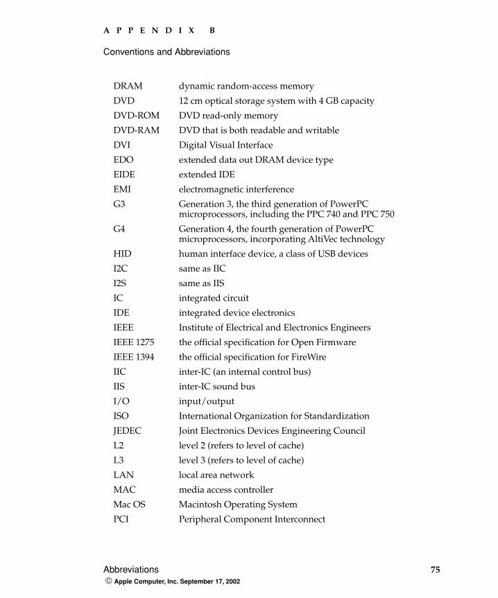
A P P E N D I X B
Conventions and Abbreviations
Abbreviations 75 Apple Computer, Inc. September 17, 2002
DRAM dynamic random-access memory
DVD 12 cm optical storage system with 4 GB capacity
DVD-ROM DVD read-only memory
DVD-RAM DVD that is both readable and writable
DVI Digital Visual Interface
EDO extended data out DRAM device type
EIDE extended IDE
EMI electromagnetic interference
G3 Generation 3, the third generation of PowerPC microprocessors, including the PPC 740 and PPC 750
G4 Generation 4, the fourth generation of PowerPC microprocessors, incorporating AltiVec technology
HID human interface device, a class of USB devices
I2C same as IIC
I2S same as IIS
IC integrated circuit
IDE integrated device electronics
IEEE Institute of Electrical and Electronics Engineers
IEEE 1275 the official specification for Open Firmware
IEEE 1394 the official specification for FireWire
IIC inter-IC (an internal control bus)
IIS inter-IC sound bus
I/O input/output
ISO International Organization for Standardization
JEDEC Joint Electronics Devices Engineering Council
L2 level 2 (refers to level of cache)
L3 level 3 (refers to level of cache)
LAN local area network
MAC media access controller
Mac OS Macintosh Operating System
PCI Peripheral Component Interconnect
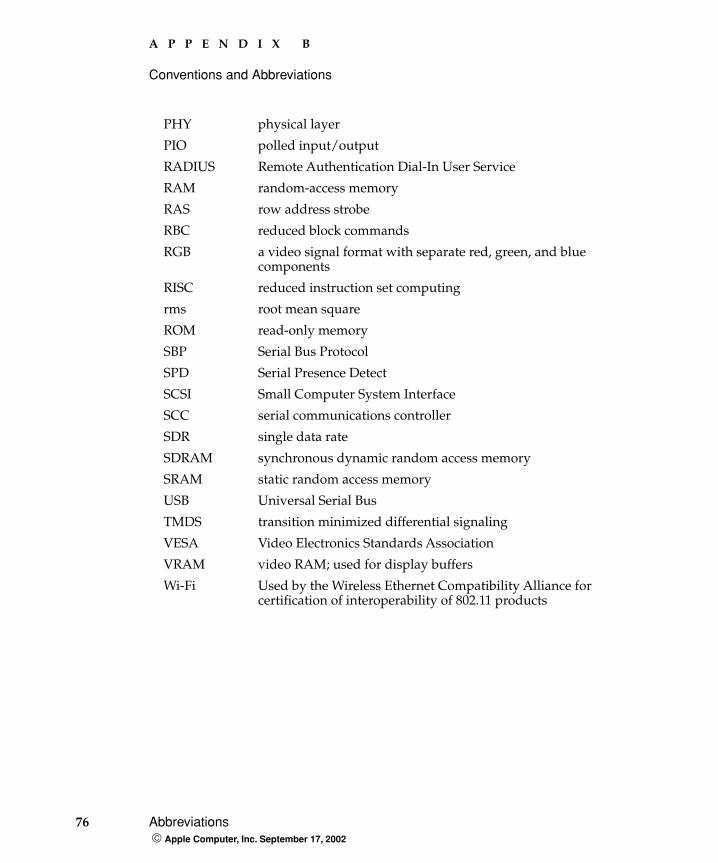
76 Abbreviations Apple Computer, Inc. September 17, 2002
A P P E N D I X B
Conventions and Abbreviations
PHY physical layer
PIO polled input/output
RADIUS Remote Authentication Dial-In User Service
RAM random-access memory
RAS row address strobe
RBC reduced block commands
RGB a video signal format with separate red, green, and blue components
RISC reduced instruction set computing
rms root mean square
ROM read-only memory
SBP Serial Bus Protocol
SPD Serial Presence Detect
SCSI Small Computer System Interface
SCC serial communications controller
SDR single data rate
SDRAM synchronous dynamic random access memory
SRAM static random access memory
USB Universal Serial Bus
TMDS transition minimized differential signaling
VESA Video Electronics Standards Association
VRAM video RAM; used for display buffers
Wi-Fi Used by the Wireless Ethernet Compatibility Alliance for certification of interoperability of 802.11 products
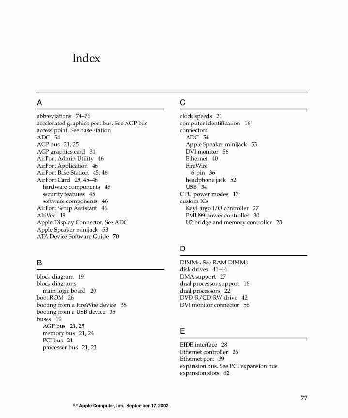
77 Apple Computer, Inc. September 17, 2002
Index
A
abbreviations 74–76accelerated graphics port bus, See AGP busaccess point. See base stationADC 54AGP bus 21, 25AGP graphics card 31AirPort Admin Utility 46AirPort Application 46AirPort Base Station 45, 46AirPort Card 29, 45–46
hardware components 46security features 45software components 46
AirPort Setup Assistant 46AltiVec 18Apple Display Connector. See ADCApple Speaker minijack 53ATA Device Software Guide 70
B
block diagram 19block diagrams
main logic board 20boot ROM 26booting from a FireWire device 38booting from a USB device 35buses 19
AGP bus 21, 25memory bus 21, 24PCI bus 21processor bus 21, 23
C
clock speeds 21computer identification 16connectors
ADC 54Apple Speaker minijack 53DVI monitor 56Ethernet 40FireWire
6-pin 36headphone jack 52USB 34
CPU power modes 17custom ICs
KeyLargo I/O controller 27PMU99 power controller 30U2 bridge and memory controller 23
D
DIMMs. See RAM DIMMsdisk drives 41–44DMA support 27dual processor support 16dual processors 22DVD-R/CD-RW drive 42DVI monitor connector 56
E
EIDE interface 28Ethernet controller 26Ethernet port 39expansion bus. See PCI expansion busexpansion slots 62
I N D E X
78 Apple Computer, Inc. September 17, 2002
F
features summary 12FireWire connectors
6-pin connector 36FireWire device programming 36FireWire drivers 36FireWire ports 36–39
booting from 38Target Disk mode 38
G
G4, See PowerPC G4 microprocessorgraphics acceleration 31
H
headphone jack 52
I, J
I/O portsEthernet 39FireWire 36sound 50USB 33video monitor 54
IDE interface 28idle state 17internal modem 44interrupts 27
K
keyboard 47–49KeyLargo I/O controller IC 27
L
logic board access 15
M
Max Bus 23memory bus 21, 24microprocessor 21microprocessor clock speeds 21model property 16modem 44modem slot 29mouse 49–50multiple processors 22Multiprocessing 2.0 SDK 66Multiprocessing Services 16
N
new features 11NMI switch 49
O
Open FirmwareTechNotes for 69
P, Q
PCI bus 21, 62PCI expansion slots 62PCI write combining 25PMU99 IC 30power controller IC 30PowerPC G4 microprocessor 21presence detect feature of DIMMs 60processor bus 21, 23processor module 21programmer’s switches 49
I N D E X
79 Apple Computer, Inc. September 17, 2002
R
RAM DIMMs 59–62capacities of 61configurations 61devices in 62installation of 59mechanical specifications of 60presence detect feature 60RAM addressing 62specifications of 60
reset switch 49ROM in RAM
boot ROM 26
S
serial presence detect (SPD) 60sound circuitry 29sound system 50–53summary of features 12SuperDrive 42
T
Target Disk Mode 38
U
U2 bridge and memory controller IC 23Ultra DMA ATA interface 24, 28Universal Serial Bus. See USBUSB connectors 34USB controller IC 28, 33USB interface 28USB ports 33–35
booting from 35data transfer speeds 34
USB with keyboard 48
V
Velocity Engine 18video monitor ports 54–58
W, X, Y, Z
wireless LAN module 29, 45–46base station 45, 46hardware components 46security features 45software components 46
write combining 25

I N D E X
80 Apple Computer, Inc. September 17, 2002