Embed Size (px)
Citation preview
1
2
3
4
5
6
7
8
Document Number: DSP1015
Date: 2008-09-29
Version: 1.0.1
Power Supply Profile
Document Type: Specification
Document Status: Final Standard
Document Language: E
9
Power Supply Profile DSP1015
2 Final Standard Version 1.0.1
Copyright Notice 10
Copyright © 2008 Distributed Management Task Force, Inc. (DMTF). All rights reserved. 11
12 13 14 15 16
17 18 19 20 21 22 23 24 25 26 27 28 29
30 31
DMTF is a not-for-profit association of industry members dedicated to promoting enterprise and systems management and interoperability. Members and non-members may reproduce DMTF specifications and documents for uses consistent with this purpose, provided that correct attribution is given. As DMTF specifications may be revised from time to time, the particular version and release date should always be noted.
Implementation of certain elements of this standard or proposed standard may be subject to third party patent rights, including provisional patent rights (herein "patent rights"). DMTF makes no representations to users of the standard as to the existence of such rights, and is not responsible to recognize, disclose, or identify any or all such third party patent right, owners or claimants, nor for any incomplete or inaccurate identification or disclosure of such rights, owners or claimants. DMTF shall have no liability to any party, in any manner or circumstance, under any legal theory whatsoever, for failure to recognize, disclose, or identify any such third party patent rights, or for such party’s reliance on the standard or incorporation thereof in its product, protocols or testing procedures. DMTF shall have no liability to any party implementing such standard, whether such implementation is foreseeable or not, nor to any patent owner or claimant, and shall have no liability or responsibility for costs or losses incurred if a standard is withdrawn or modified after publication, and shall be indemnified and held harmless by any party implementing the standard from any and all claims of infringement by a patent owner for such implementations.
For information about patents held by third-parties which have notified the DMTF that, in their opinion, such patent may relate to or impact implementations of DMTF standards, visit http://www.dmtf.org/about/policies/disclosures.php. 32
DSP1015 Power Supply Profile
Version 1.0.1 Final Standard 3
CONTENTS 33
34 35 36 37 38 39 40 41 42 43 44 45 46 47 48 49 50 51 52 53 54 55 56 57 58 59 60 61 62 63 64 65 66 67 68 69 70 71 72 73 74 75 76 77 78 79 80 81 82 83 84 85 86
Foreword ....................................................................................................................................................... 5 Introduction ................................................................................................................................................... 6 1 Scope .................................................................................................................................................... 7 2 Normative References........................................................................................................................... 7
2.1 Approved References ................................................................................................................. 7 2.2 Other References........................................................................................................................ 7
3 Terms and Definitions ........................................................................................................................... 7 4 Symbols and Abbreviated Terms .......................................................................................................... 8 5 Synopsis................................................................................................................................................ 9 6 Description ............................................................................................................................................ 9
6.1 Power Supply Redundancy ...................................................................................................... 10 7 Implementation Requirements ............................................................................................................ 10
7.1 CIM_PowerSupply .................................................................................................................... 10 7.2 CIM_EnabledLogicalElementCapabilities................................................................................. 10 7.3 Power Supply State Management ............................................................................................ 11 7.4 CIM_PowerSupply.RequestedState ......................................................................................... 11 7.5 CIM_PowerSupply.EnabledState ............................................................................................. 12 7.6 CIM_SystemDevice and CIM_SuppliesPower ......................................................................... 12 7.7 Modeling Power Supply Redundancy....................................................................................... 12 7.8 CIM_PowerSupply.ElementName ............................................................................................ 13
8 Methods............................................................................................................................................... 13 8.1 Method: CIM_PowerSupply.RequestStateChange( ) ............................................................... 13 8.2 Method: CIM_RedundancySet.Failover( ) ................................................................................ 14 8.3 Profile Conventions for Operations........................................................................................... 16 8.4 CIM_ElementCapabilities Operations....................................................................................... 16 8.5 CIM_EnabledLogicalElementCapabilities Operations .............................................................. 16 8.6 CIM_IsSpare Operations .......................................................................................................... 16 8.7 CIM_MemberOfCollection Operations...................................................................................... 17 8.8 CIM_OwningCollectionElement Operations ............................................................................. 17 8.9 CIM_PowerSupply Operations ................................................................................................. 17 8.10 CIM_RedundancySet Operations ............................................................................................. 18 8.11 CIM_SuppliesPower Operations............................................................................................... 18 8.12 CIM_SystemDevice Operations................................................................................................ 18
9 Use Cases........................................................................................................................................... 18 9.1 Object Diagrams ....................................................................................................................... 18 9.2 Retrieve the Power Supply’s Power Output Information .......................................................... 21 9.3 Reset the Power Supply ........................................................................................................... 21 9.4 Retrieve the Power Supply Redundancy Status....................................................................... 21 9.5 Find the Elements to Which the Power Supply Supplies Power .............................................. 21 9.6 Determine Whether the CIM_PowerSupply.ElementName Is Modifiable ................................ 22
10 CIM Elements...................................................................................................................................... 23 10.1 CIM_ElementCapabilities ......................................................................................................... 23 10.2 CIM_EnabledLogicalElementCapabilities................................................................................. 23 10.3 CIM_IsSpare ............................................................................................................................. 24 10.4 CIM_MemberOfCollection ........................................................................................................ 24 10.5 CIM_PowerSupply .................................................................................................................... 24 10.6 CIM_RedundancySet................................................................................................................ 25 10.7 CIM_RegisteredProfile.............................................................................................................. 25 10.8 CIM_SystemDevice .................................................................................................................. 26 10.9 CIM_OwningCollectionElement ................................................................................................ 26 10.10 CIM_SuppliesPower ................................................................................................................. 26
ANNEX A (informative) Change Log.......................................................................................................... 27 ANNEX B (informative) Acknowledgments ................................................................................................ 28
Power Supply Profile DSP1015
4 Final Standard Version 1.0.1
Figures 87
88 89 90 91 92
Figure 1 – Power Supply Profile: Class Diagram........................................................................................ 10 Figure 2 – Power Supply Profile: Object Diagram ...................................................................................... 19 Figure 3 – Power Supply Profile: Redundancy Object Diagram................................................................. 20 Figure 4 – Power Supply Profile: Dedicated Power Supply........................................................................ 21
Tables 93
94 95 96 97 98 99
100 101 102 103 104 105 106 107 108 109 110 111 112 113 114 115 116 117
118
Table 1 – Referenced Profiles ...................................................................................................................... 9 Table 2 – EnabledState Value Description ................................................................................................. 12 Table 3 – CIM_PowerSupply.RequestStateChange( ) Method: Return Code Values................................ 14 Table 4 – CIM_PowerSupply.RequestStateChange( ) Method: Parameters ............................................. 14 Table 5 – CIM_RedundancySet.Failover( ) Method: Return Code Values................................................. 15 Table 6 – CIM_RedundancySet.Failover( ) Method: Parameters............................................................... 15 Table 7 – CIM_ElementCapabilities Operations......................................................................................... 16 Table 8 – CIM_IsSpare Operations ............................................................................................................ 16 Table 9 – CIM_MemberOfCollection Operations........................................................................................ 17 Table 10 – CIM_OwningCollectionElement Operations ............................................................................. 17 Table 11 – CIM_PowerSupply Operations.................................................................................................. 17 Table 12 – CIM_SuppliesPower Operations............................................................................................... 18 Table 13 – CIM_SystemDevice Operations................................................................................................ 18 Table 14 – CIM Elements: Power Supply Profile ........................................................................................ 23 Table 15 – CIM_ElementCapabilities.......................................................................................................... 23 Table 16 – CIM_EnabledLogicalElementCapabilities................................................................................. 23 Table 17 – Class: CIM_IsSpare .................................................................................................................. 24 Table 18 – Class: CIM_MemberOfCollection.............................................................................................. 24 Table 19 – Class: CIM_PowerSupply ......................................................................................................... 24 Table 20 – Class: CIM_RedundancySet..................................................................................................... 25 Table 21 – Class: CIM_RegisteredProfile................................................................................................... 25 Table 22 – Class: CIM_SystemDevice ....................................................................................................... 26 Table 23 – Class: CIM_OwningCollectionElement ..................................................................................... 26 Table 24 – Class: CIM_SuppliesPower ...................................................................................................... 26
DSP1015 Power Supply Profile
Version 1.0.1 Final Standard 5
Foreword 119
120
121 122
The Power Supply Profile (DSP1015) was prepared by the Server Management Working Group.
DMTF is a not-for-profit association of industry members dedicated to promoting enterprise and systems management and interoperability.
Power Supply Profile DSP1015
6 Final Standard Version 1.0.1
Introduction 123
124 125 126 127 128
129 130
The information in this specification and referenced specifications should be sufficient for a provider or consumer of this data to identify unambiguously the classes, properties, methods, and values that shall be instantiated and manipulated to represent and manage power supplies and redundant power supplies of managed systems and subsystems that are modeled using the DMTF CIM core and extended model definitions.
The target audience for this specification is implementers who are writing CIM-based providers or consumers of management interfaces that represent the component described in this document.
DSP1015 Power Supply Profile
Version 1.0.1 Final Standard 7
Power Supply Profile 131
132
133 134 135 136 137
138
139 140 141
142
1 Scope The Power Supply Profile extends the management capabilities of referencing profiles by adding the capability to represent power supplies for manageability and describe power supplies in a redundant configuration. The power supply as a logical device is modeled as referencing the power supply physical package for physical asset information and profile versioning for the schema implementation version information.
2 Normative References The following referenced documents are indispensable for the application of this document. For dated references, only the edition cited applies. For undated references, the latest edition of the referenced document (including any amendments) applies.
2.1 Approved References
DMTF DSP0200, CIM Operations over HTTP 1.2.0 143
DMTF DSP0004, CIM Infrastructure Specification 2.3.0 144
DMTF DSP1000, Management Profile Specification Template 1.0.0 145
DMTF DSP1001, Management Profile Specification Usage Guide 1.0.0 146
DMTF DSP1011, Physical Asset Profile 1.0.0 147
DMTF DSP1033, Profile Registration Profile 1.0.0 148
149 2.2 Other References
ISO/IEC Directives, Part 2, Rules for the structure and drafting of International Standards150
OMG, Unified Modeling Language (UML) from the Open Management Group (OMG) 151
152
153
154 155 156
157 158 159
160 161 162 163
3 Terms and Definitions For the purposes of this document, the following terms and definitions apply.
3.1 can used for statements of possibility and capability, whether material, physical, or causal
3.2 cannot used for statements of possibility and capability, whether material, physical, or causal
3.3 conditional indicates requirements to be followed strictly in order to conform to the document when the specified conditions are met
Power Supply Profile DSP1015
8 Final Standard Version 1.0.1
3.4 164 165 166 167
168 169 170
171 172 173
174 175 176
177 178 179 180
181 182 183 184
185 186 187 188
189 190 191 192
193 194 195
196 197 198
199
200 201 202
203 204 205
mandatory indicates requirements to be followed strictly in order to conform to the document and from which no deviation is permitted
3.5 may indicates a course of action permissible within the limits of the document
3.6 need not indicates a course of action permissible within the limits of the document
3.7 optional indicates a course of action permissible within the limits of the document
3.8 referencing profile indicates a profile that owns the definition of this class and can include a reference to this profile in its “Referenced Profiles” table
3.9 shall indicates requirements to be followed strictly in order to conform to the document and from which no deviation is permitted
3.10 shall not indicates requirements to be followed strictly in order to conform to the document and from which no deviation is permitted
3.11 should indicates that among several possibilities, one is recommended as particularly suitable, without mentioning or excluding others, or that a certain course of action is preferred but not necessarily required
3.12 should not indicates that a certain possibility or course of action is deprecated but not prohibited
3.13 Spare Power Supply indicates an instance of CIM_PowerSupply that represents a spare power supply in any condition
4 Symbols and Abbreviated Terms 4.1 CIM Common Information Model
4.2 FRU Field Replaceable Unit
DSP1015 Power Supply Profile
Version 1.0.1 Final Standard 9
5 Synopsis 206
207
208
209
210
211
212
213 214
215
216
Profile Name: Power Supply
Version: 1.0.1
Organization: DMTF
CIM Schema Version: 2.19.1
Central Class: CIM_PowerSupply
Scoping Class: CIM_ComputerSystem
The Power Supply Profile extends the management capability of the referencing profiles by adding the capability to describe power supplies and redundant power supplies.
Table 1 identifies profiles on which this profile has a dependency.
Table 1 – Related Profiles
Profile Name Organization Version Requirement Description
Physical Asset DMTF 1.0.0 Optional
Profile Registration DMTF 1.0.0 Mandatory
217
218
219 220 221
222 223
224 225 226
227 228 229 230 231
232 233
234
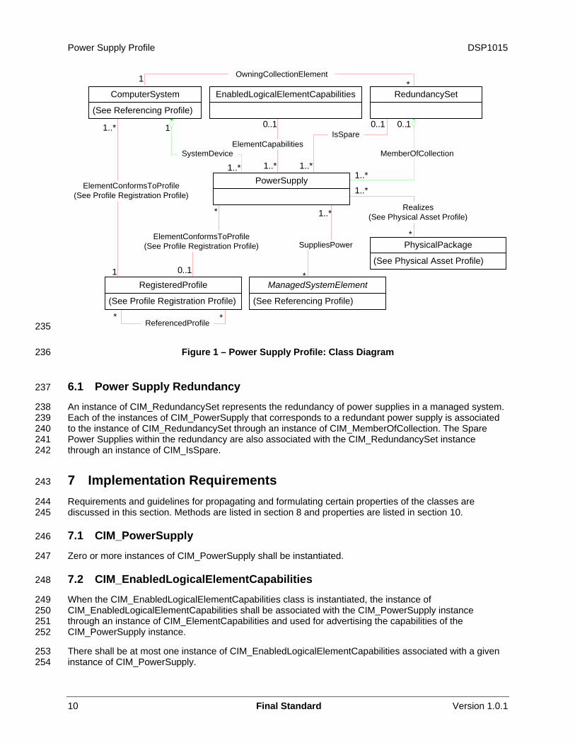
6 Description The Power Supply Profile describes power supplies and power supply redundancies in a managed system. The profile also describes the relationship of the power supply class to the power supply’s physical aspects, such as FRU data, and DMTF profile version information.
Figure 1 represents the class schema for the Power Supply Profile. For simplicity, the prefix CIM_ has been removed from the names of the classes.
The power supply in a managed system is represented by the instance of CIM_PowerSupply. The capability to disable and enable the power supply is advertised through the CIM_EnabledLogicalElementCapabilities instance.
The managed elements that receive power from the power supply are associated to the instance of CIM_PowerSupply through an instance of CIM_SuppliesPower. When the CIM_PowerSupply instance is not referenced by the CIM_SuppliesPower association, the power supply represented by the CIM_PowerSupply instance supplies power to the managed system that is scoped through the CIM_SystemDevice association.
The power supply’s physical aspects can be represented by one or more instances of CIM_PhysicalPackage.
The profile information is represented with the instance of CIM_RegisteredProfile.
Power Supply Profile DSP1015
* *
1
1..*
0..11
*
1..*
1..*1..*
0..1
1..*
*
ElementCapabilities
0..1
1..*
0..1
*
1 *
1..*
ComputerSystem
(See Referencing Profile)
EnabledLogicalElementCapabilities RedundancySet
PowerSupply
ManagedSystemElement
(See Referencing Profile)
RegisteredProfile
(See Profile Registration Profile)
PhysicalPackage
(See Physical Asset Profile)
SystemDevice
IsSpare
MemberOfCollection
SuppliesPower
ReferencedProfile
ElementConformsToProfile(See Profile Registration Profile)
ElementConformsToProfile(See Profile Registration Profile)
Realizes(See Physical Asset Profile)
OwningCollectionElement
235
236
237
238 239 240 241 242
243
244 245
246
247
248
249 250 251 252
253 254
Figure 1 – Power Supply Profile: Class Diagram
6.1 Power Supply Redundancy
An instance of CIM_RedundancySet represents the redundancy of power supplies in a managed system. Each of the instances of CIM_PowerSupply that corresponds to a redundant power supply is associated to the instance of CIM_RedundancySet through an instance of CIM_MemberOfCollection. The Spare Power Supplies within the redundancy are also associated with the CIM_RedundancySet instance through an instance of CIM_IsSpare.
7 Implementation Requirements Requirements and guidelines for propagating and formulating certain properties of the classes are discussed in this section. Methods are listed in section 8 and properties are listed in section 10.
7.1 CIM_PowerSupply
Zero or more instances of CIM_PowerSupply shall be instantiated.
7.2 CIM_EnabledLogicalElementCapabilities
When the CIM_EnabledLogicalElementCapabilities class is instantiated, the instance of CIM_EnabledLogicalElementCapabilities shall be associated with the CIM_PowerSupply instance through an instance of CIM_ElementCapabilities and used for advertising the capabilities of the CIM_PowerSupply instance.
There shall be at most one instance of CIM_EnabledLogicalElementCapabilities associated with a given instance of CIM_PowerSupply.
10 Final Standard Version 1.0.1
DSP1015 Power Supply Profile
Version 1.0.1 Final Standard 11
7.2.1 CIM_EnabledLogicalElementCapabilities.RequestedStatesSupported 255
256 257 258 259 260 261
262
263 264
265
266 267
268
269 270 271
272
273 274
275 276 277
278 279 280
281
282 283 284 285
286 287 288 289 290 291
292
293 294
CIM_EnabledLogicalElementCapabilities.RequestedStatesSupported is an array that contains the supported requested states for the instance of CIM_PowerSupply. This property shall be the super set of the values to be used as the RequestedState parameter in the RequestStateChange( ) method (see section 8.1). The value of the CIM_EnabledLogicalElementCapabilities.RequestedStatesSupported property shall be an empty array or contain any combination of the following values: 2 (Enabled), 3 (Disabled), 6 (Offline), or 11 (Reset).
7.2.2 CIM_EnabledLogicalElementCapabilities.ElementNameEditSupported
This property shall have a value of TRUE when the implementation supports client modification of the CIM_PowerSupply.ElementName property.
7.2.3 CIM_EnabledLogicalElementCapabilities.MaxElementNameLen
The MaxElementNameLen property shall be implemented when the ElementNameEditSupported property has a value of TRUE.
7.3 Power Supply State Management
Power supply state management is optional. The power supply state management consists of the CIM_PowerSupply.RequestStateChange( ) method being supported (see section 8.1) and the value of the CIM_PowerSupply.RequestedState not matching 12 (Not Applicable).
7.3.1 Power Supply State Management Support
When no CIM_EnabledLogicalElementCapabilities instance is associated with the CIM_PowerSupply instance, the power supply state management shall not be supported.
When a CIM_EnabledLogicalElementCapabilities instance is associated with the CIM_PowerSupply instance but the value of the CIM_EnabledLogicalElementCapabilities.RequestedStatesSupported property is an empty array, the power supply state management shall not be supported.
When a CIM_EnabledLogicalElementCapabilities instance is associated with the CIM_PowerSupply instance and the value of the CIM_EnabledLogicalElementCapabilities.RequestedStatesSupported property is not an empty array, the power supply state management shall be supported.
7.4 CIM_PowerSupply.RequestedState
The CIM_PowerSupply.RequestedState property shall have a value of 12 (Not Applicable), 5 (No Change), or a value contained in the CIM_EnabledLogicalElementCapabilities.RequestedStatesSupported property array of the associated CIM_EnabledLogicalElementCapabilities instance (see section 7.2.1).
When the power supply state management is supported and the RequestStateChange( ) method is successfully executed, the RequestedState property shall be set to the value of the parameter RequestedState of RequestStateChange( ) method. After the RequestStateChange( ) method has successfully executed, RequestedState and EnabledState shall have equal values with the exception of the transitional requested state 11 (Reset). The value of the RequestedState property may also change as a result of a request for change to the power supply’s enabled state by non-CIM implementation.
7.4.1 RequestedState – 12 (Not Applicable) Value
When the power supply state management is not supported, the value of the CIM_PowerSupply.RequestedState property shall be 12 (Not Applicable).
Power Supply Profile DSP1015
12 Final Standard Version 1.0.1
7.4.2 RequestedState – 5 (No Change) Value 295
296 297
298
299 300 301 302 303 304 305
306
When the power supply state management is supported, the initial value of the CIM_PowerSupply.RequestedState property shall be 5 (No Change).
7.5 CIM_PowerSupply.EnabledState
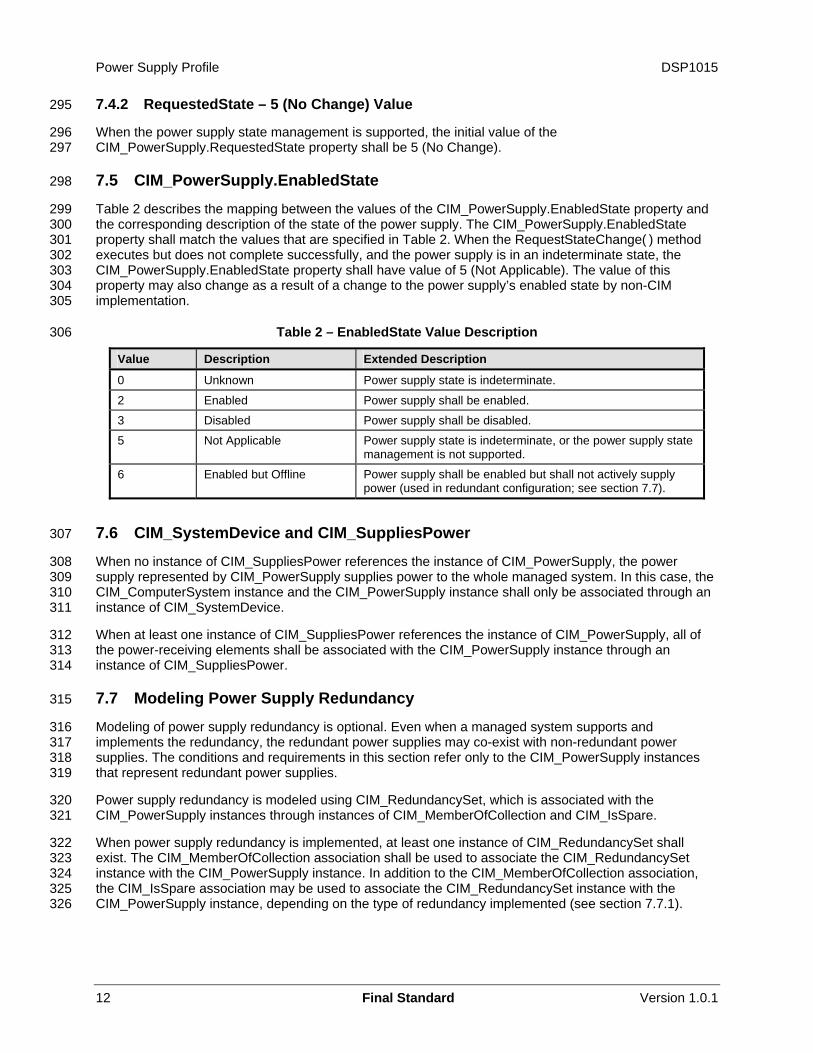
Table 2 describes the mapping between the values of the CIM_PowerSupply.EnabledState property and the corresponding description of the state of the power supply. The CIM_PowerSupply.EnabledState property shall match the values that are specified in Table 2. When the RequestStateChange( ) method executes but does not complete successfully, and the power supply is in an indeterminate state, the CIM_PowerSupply.EnabledState property shall have value of 5 (Not Applicable). The value of this property may also change as a result of a change to the power supply’s enabled state by non-CIM implementation.
Table 2 – EnabledState Value Description
Value Description Extended Description
0 Unknown Power supply state is indeterminate.
2 Enabled Power supply shall be enabled.
3 Disabled Power supply shall be disabled.
5 Not Applicable Power supply state is indeterminate, or the power supply state management is not supported.
6 Enabled but Offline Power supply shall be enabled but shall not actively supply power (used in redundant configuration; see section 7.7).
7.6 CIM_SystemDevice and CIM_SuppliesPower 307
308 309 310 311
312 313 314
315
316 317 318 319
320 321
322 323 324 325 326
When no instance of CIM_SuppliesPower references the instance of CIM_PowerSupply, the power supply represented by CIM_PowerSupply supplies power to the whole managed system. In this case, the CIM_ComputerSystem instance and the CIM_PowerSupply instance shall only be associated through an instance of CIM_SystemDevice.
When at least one instance of CIM_SuppliesPower references the instance of CIM_PowerSupply, all of the power-receiving elements shall be associated with the CIM_PowerSupply instance through an instance of CIM_SuppliesPower.
7.7 Modeling Power Supply Redundancy
Modeling of power supply redundancy is optional. Even when a managed system supports and implements the redundancy, the redundant power supplies may co-exist with non-redundant power supplies. The conditions and requirements in this section refer only to the CIM_PowerSupply instances that represent redundant power supplies.
Power supply redundancy is modeled using CIM_RedundancySet, which is associated with the CIM_PowerSupply instances through instances of CIM_MemberOfCollection and CIM_IsSpare.
When power supply redundancy is implemented, at least one instance of CIM_RedundancySet shall exist. The CIM_MemberOfCollection association shall be used to associate the CIM_RedundancySet instance with the CIM_PowerSupply instance. In addition to the CIM_MemberOfCollection association, the CIM_IsSpare association may be used to associate the CIM_RedundancySet instance with the CIM_PowerSupply instance, depending on the type of redundancy implemented (see section 7.7.1).
DSP1015 Power Supply Profile
Version 1.0.1 Final Standard 13
7.7.1 CIM_RedundancySet.TypeOfSet 327
328 329 330
331 332
333 334
335
336 337 338
339 340
341
342 343 344
345 346 347
348 349 350
351
352 353
354
355 356 357 358 359
360
361 362
363
364 365
When the CIM_RedundancySet.TypeOfSet property contains a value of 3 (Load Balanced), and/or 2 (N+1), or both, and does not contain any other values, the CIM_PowerSupply instances that are associated with the CIM_RedundancySet instance shall comply with the following requirements:
• The CIM_PowerSupply instances shall be associated with the CIM_RedundancySet instance through an instance of CIM_MemberOfCollection.
• The CIM_PowerSupply instances shall not be associated with the CIM_RedundancySet instance through an instance of CIM_IsSpare.
• The CIM_PowerSupply.EnabledState property shall not have value of 6 (Enabled but Offline).
When the CIM_RedundancySet.TypeOfSet property has a value of 4 (Sparing), 5 (Limited Sparing), or both, Spare Power Supplies may exist. The Spare Power Supply shall be associated with the CIM_RedundancySet instance and shall comply with the following requirements:
• The Spare Power Supply shall be associated with the CIM_RedundancySet through instances of both CIM_IsSpare and CIM_MemberOfCollection.
• The Spare Power Supply shall comply to one of the following requirements:
– When the CIM_PowerSupply.EnabledState property has a value of 6 (Enabled but Offline), the SpareStatus property of the referencing CIM_IsSpare instance shall have a value of 2 (Hot Standby).
– When the CIM_PowerSupply.EnabledState property has a value of 3 (Disabled), the SpareStatus property of the referencing CIM_IsSpare instance shall have a value of 3 (Cold Standby).
– When the CIM_PowerSupply.EnabledState property has a value other than 3 (Disabled) or 6 (Enabled but Offline), the SpareStatus property of the referencing CIM_IsSpare instance shall have a value of 0 (Unknown).
7.8 CIM_PowerSupply.ElementName
The CIM_PowerSupply.ElementName property shall be formatted as a free-form string of variable length (pattern “.*”).
7.8.1 CIM_PowerSupply.ElementName Is Modifiable
Implementations may allow the CIM_PowerSupply.ElementName to be modified by a client. This behavior is conditional. This section describes the CIM elements and behavior requirements when an implementation supports client modification of the CIM_PowerSupply.ElementName property. CIM_PowerSupply.ElementName property shall be modifiable when the ElementNameEditSupported property of the associated CIM_EnabledLogicalElementCapabilities instance has a value of TRUE.
8 Methods This section details the requirements for supporting intrinsic operations and extrinsic methods for the CIM elements defined by this profile.
8.1 Method: CIM_PowerSupply.RequestStateChange( )
Invocation of the CIM_PowerSupply.RequestStateChange( ) method will change the element’s state to the value that is specified in the RequestedState parameter.
Power Supply Profile DSP1015
14 Final Standard Version 1.0.1
Return values for RequestStateChange( ) shall be as specified in Table 3 where the method-execution behavior matches the return-code description. RequestStateChange( ) method’s parameters are specified in
366 367 368
369 370
371 372
373 374
375
376
Table 4.
When the power supply state management is supported, the RequestStateChange( ) method shall be implemented and shall not return a value of 1 (Not Supported) (see section 7.3.1).
When the value of the RequestedState parameter is 6 (Offline) and the power supply is not a Spare Power Supply, the RequestStateChange( ) method shall return a value of 2 (Error Occurred).
Invoking the CIM_PowerSupply.RequestStateChange( ) method multiple times could result in earlier requests being overwritten or lost.
No standard messages are defined for this method.
Table 3 – CIM_PowerSupply.RequestStateChange( ) Method: Return Code Values
Value Description
0 Request was successfully executed.
1 Method is not supported in the implementation.
2 Error occurred
4096 Job started
Table 4 – CIM_PowerSupply.RequestStateChange( ) Method: Parameters 377
Qualifiers Name Type Description/Values
IN RequestedState uint16 Valid state values: 2 (Enabled) 3 (Disabled) (see section 8.1.1) 6 (Offline) (see section 8.1.1) 11 (Reset)
OUT Job CIM_ConcreteJob REF Returned if job started
IN TimeoutPeriod Datetime Client specified maximum amount of time the transition to a new state is supposed to take: 0 or NULL – No time requirements <interval> – Maximum time allowed
8.1.1 RequestStateChange( ) for the Spare Power Supply 378
379 380 381
382 383 384
385
386 387 388
After the successful execution of the RequestStateChange( ) method on the Spare Power Supply with the RequestedState parameter set to 6 (Offline), the SpareStatus of the referenced CIM_IsSpare association shall have value of 2 (Hot Standby).
After the successful execution of the RequestStateChange( ) method on the Spare Power Supply with the RequestedState parameter set to 3 (Disabled), the SpareStatus of the referenced CIM_IsSpare association shall have value of 3 (Cold Standby).
8.2 Method: CIM_RedundancySet.Failover( )
The CIM_RedundancySet.Failover( ) method forces a failover from one member of a CIM_RedundancySet collection to another. When the method executes successfully, the power supply that is represented by the CIM_PowerSupply instance referenced by the FailoverFrom parameter will
DSP1015 Power Supply Profile
Version 1.0.1 Final Standard 15
become inactive. The power supply that is represented by the CIM_PowerSupply instance referenced by the FailoverTo parameter will take over as the active power supply.
389 390
391 392 393
394 395
396 397
398 399
400 401 402
403
404 405 406 407
408 409
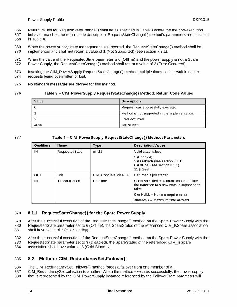
410 411 412
413 414
415
416
The Failover( ) method may be supported if the FailoverSupported property of at least one instance of CIM_IsSpare that references the CIM_RedundancySet has a value of 3 (Manual) or 4 (Both Manual and Automatic).
The Failover( ) method shall not be supported if the FailoverSupported property of every instance of CIM_IsSpare that references the CIM_RedundancySet has a value of 2 (Automatic).
The execution of the Failover( ) method shall return a value of 2 (Error Occurred) under the following conditions:
• The CIM_PowerSupply instance that is referenced by the FailoverTo parameter is not a Spare Power Supply.
• The CIM_PowerSupply instance that is referenced by the FailoverFrom parameter is not associated with the CIM_RedundancySet instance only through the CIM_MemberOfCollection association.
After the Failover( ) method executes successfully:
• The CIM_PowerSupply instance that is referenced by the FailoverTo parameter shall take over as the active power supply. The CIM_PowerSupply instance that is referenced by the FailoverTo parameter shall be associated with the CIM_RedundancySet only through the CIM_MemberOfCollection association.
• The CIM_PowerSupply instance that is referenced by FailoverFrom parameter shall become a Spare Power Supply.
• When the power supply state management is supported, the EnabledState property of the CIM_PowerSupply instance that is referenced by the FailoverFrom parameter shall not have a value of 2 (Enabled) but may have a value of 6 (Enabled but Offline).
CIM_RedundancySet.Failover( ) return values shall be as specified in Table 5. CIM_RedundancySet.Failover( ) parameters are specified in Table 6.
No standard messages are defined for this method.
Table 5 – CIM_RedundancySet.Failover( ) Method: Return Code Values
Value Description
0 Request was successfully executed.
1 Method is not supported in the implementation.
2 Error occurred
Table 6 – CIM_RedundancySet.Failover( ) Method: Parameters 417
Qualifiers Name Type Description/Values
IN, REQ FailoverFrom CIM_ManagedElement REF
The redundant element that will become inactive
IN, REQ FailoverTo CIM_ManagedElement REF
The redundant element that will become active and take over the inactivated element
Power Supply Profile DSP1015
16 Final Standard Version 1.0.1
8.3 Profile Conventions for Operations 418
419 420
Support for operations for each profile class (including associations) is specified in the following subclauses. Each subclause includes either the statement “All operations in the default list in section 8.3 are supported as described by DSP0200 version 1.2” or a table listing all of the operations that are not supported by this profile or where the profile requires behavior other than that described by
421 DSP0200 422
version 1.2. 423
424
425
426
427
428
429
430
431
432 433
434
The default list of operations is as follows:
• GetInstance
• EnumerateInstances
• EnumerateInstanceNames
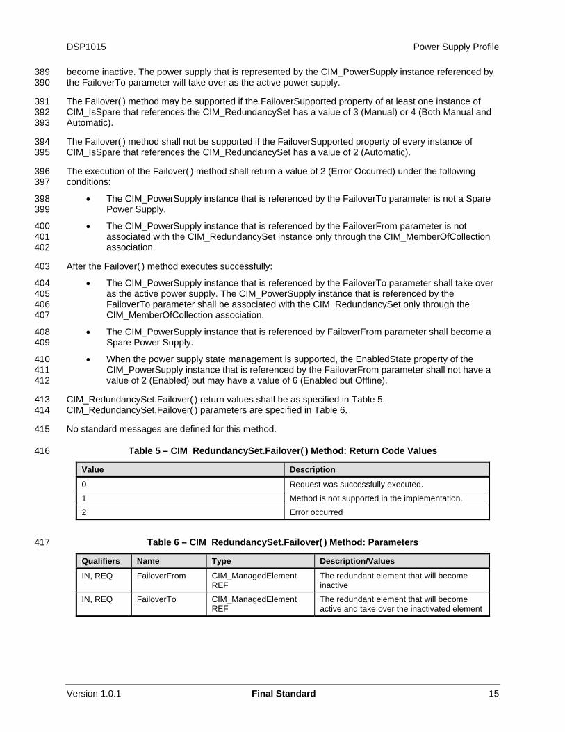
• Associators
• AssociatorNames
• References
• ReferenceNames
A compliant implementation shall support all of the operations in the default list for each class, unless the “Requirement” column states something other than Mandatory.
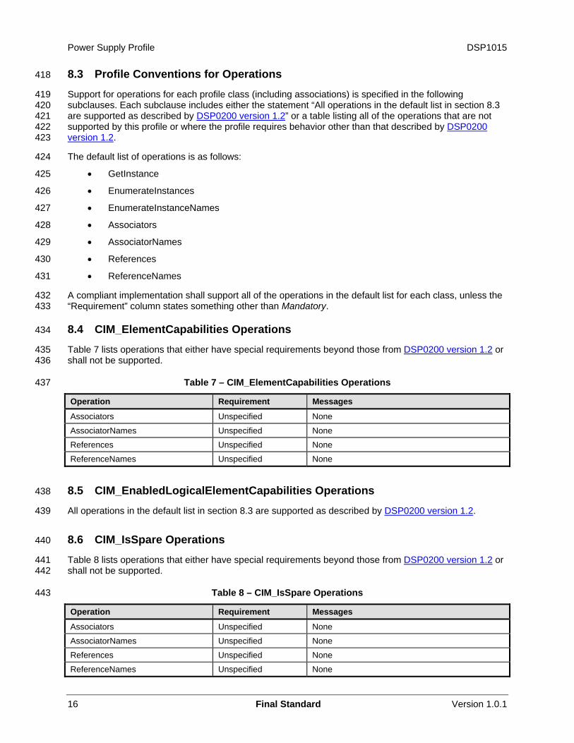
8.4 CIM_ElementCapabilities Operations
Table 7 lists operations that either have special requirements beyond those from DSP0200 version 1.2 or shall not be supported.
435 436
437 Table 7 – CIM_ElementCapabilities Operations
Operation Requirement Messages
Associators Unspecified None
AssociatorNames Unspecified None
References Unspecified None
ReferenceNames Unspecified None
8.5 CIM_EnabledLogicalElementCapabilities Operations 438
All operations in the default list in section 8.3 are supported as described by DSP0200 version 1.2. 439
440 8.6 CIM_IsSpare Operations
Table 8 lists operations that either have special requirements beyond those from DSP0200 version 1.2 or shall not be supported.
441 442
443 Table 8 – CIM_IsSpare Operations
Operation Requirement Messages
Associators Unspecified None
AssociatorNames Unspecified None
References Unspecified None
ReferenceNames Unspecified None
DSP1015 Power Supply Profile
Version 1.0.1 Final Standard 17
8.7 CIM_MemberOfCollection Operations 444
Table 9 lists operations that either have special requirements beyond those from DSP0200 version 1.2 or shall not be supported.
445 446
447 Table 9 – CIM_MemberOfCollection Operations
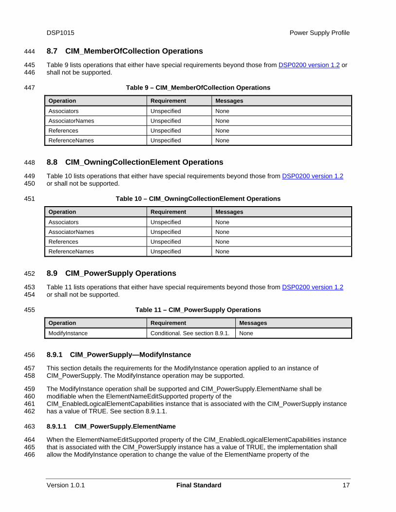
Operation Requirement Messages
Associators Unspecified None
AssociatorNames Unspecified None
References Unspecified None
ReferenceNames Unspecified None
8.8 CIM_OwningCollectionElement Operations 448
Table 10 lists operations that either have special requirements beyond those from DSP0200 version 1.2 or shall not be supported.
449 450
451 Table 10 – CIM_OwningCollectionElement Operations
Operation Requirement Messages
Associators Unspecified None
AssociatorNames Unspecified None
References Unspecified None
ReferenceNames Unspecified None
8.9 CIM_PowerSupply Operations 452
Table 11 lists operations that either have special requirements beyond those from DSP0200 version 1.2 or shall not be supported.
453 454
455 Table 11 – CIM_PowerSupply Operations
Operation Requirement Messages
ModifyInstance Conditional. See section 8.9.1. None
8.9.1 CIM_PowerSupply—ModifyInstance 456
457 458
459 460 461 462
463
464 465 466
This section details the requirements for the ModifyInstance operation applied to an instance of CIM_PowerSupply. The ModifyInstance operation may be supported.
The ModifyInstance operation shall be supported and CIM_PowerSupply.ElementName shall be modifiable when the ElementNameEditSupported property of the CIM_EnabledLogicalElementCapabilities instance that is associated with the CIM_PowerSupply instance has a value of TRUE. See section 8.9.1.1.
8.9.1.1 CIM_PowerSupply.ElementName
When the ElementNameEditSupported property of the CIM_EnabledLogicalElementCapabilities instance that is associated with the CIM_PowerSupply instance has a value of TRUE, the implementation shall allow the ModifyInstance operation to change the value of the ElementName property of the
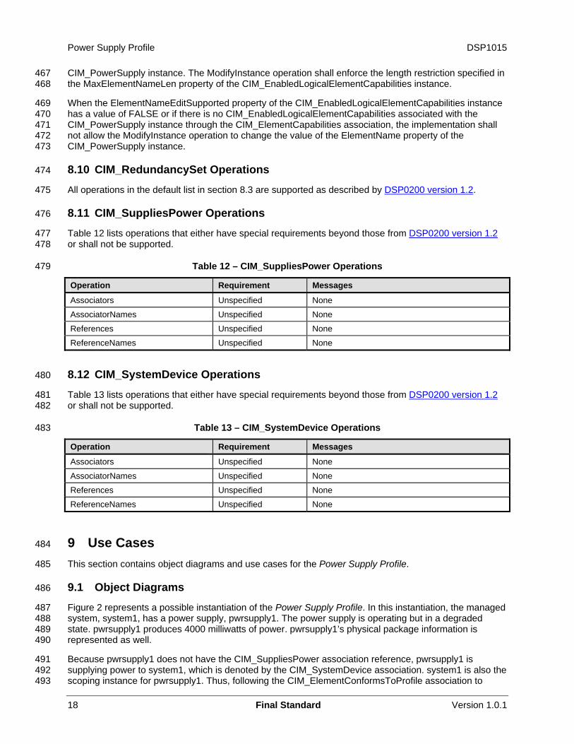
Power Supply Profile DSP1015
18 Final Standard Version 1.0.1
CIM_PowerSupply instance. The ModifyInstance operation shall enforce the length restriction specified in the MaxElementNameLen property of the CIM_EnabledLogicalElementCapabilities instance.
467 468
469 470 471 472 473
474
When the ElementNameEditSupported property of the CIM_EnabledLogicalElementCapabilities instance has a value of FALSE or if there is no CIM_EnabledLogicalElementCapabilities associated with the CIM_PowerSupply instance through the CIM_ElementCapabilities association, the implementation shall not allow the ModifyInstance operation to change the value of the ElementName property of the CIM_PowerSupply instance.
8.10 CIM_RedundancySet Operations
All operations in the default list in section 8.3 are supported as described by DSP0200 version 1.2. 475
476 8.11 CIM_SuppliesPower Operations
Table 12 lists operations that either have special requirements beyond those from DSP0200 version 1.2 or shall not be supported.
477 478
479 Table 12 – CIM_SuppliesPower Operations
Operation Requirement Messages
Associators Unspecified None
AssociatorNames Unspecified None
References Unspecified None
ReferenceNames Unspecified None
8.12 CIM_SystemDevice Operations 480
Table 13 lists operations that either have special requirements beyond those from DSP0200 version 1.2 or shall not be supported.
481 482
483 Table 13 – CIM_SystemDevice Operations
Operation Requirement Messages
Associators Unspecified None
AssociatorNames Unspecified None
References Unspecified None
ReferenceNames Unspecified None
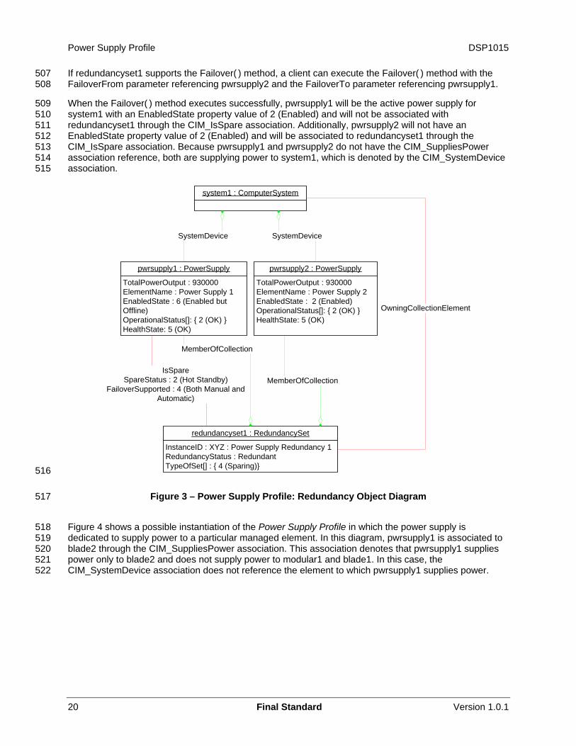
9 Use Cases 484
485
486
487 488 489 490
491 492 493
This section contains object diagrams and use cases for the Power Supply Profile.
9.1 Object Diagrams
Figure 2 represents a possible instantiation of the Power Supply Profile. In this instantiation, the managed system, system1, has a power supply, pwrsupply1. The power supply is operating but in a degraded state. pwrsupply1 produces 4000 milliwatts of power. pwrsupply1’s physical package information is represented as well.
Because pwrsupply1 does not have the CIM_SuppliesPower association reference, pwrsupply1 is supplying power to system1, which is denoted by the CIM_SystemDevice association. system1 is also the scoping instance for pwrsupply1. Thus, following the CIM_ElementConformsToProfile association to
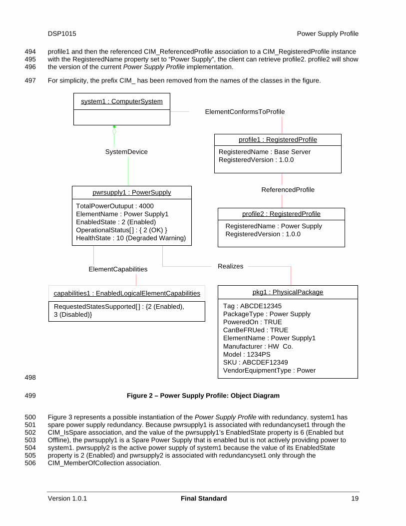
DSP1015 Power Supply Profile
494 495 496
497
profile1 and then the referenced CIM_ReferencedProfile association to a CIM_RegisteredProfile instance with the RegisteredName property set to “Power Supply”, the client can retrieve profile2. profile2 will show the version of the current Power Supply Profile implementation.
For simplicity, the prefix CIM_ has been removed from the names of the classes in the figure.
pwrsupply1 : PowerSupply
TotalPowerOutuput : 4000ElementName : Power Supply1EnabledState : 2 (Enabled)OperationalStatus[ ] : { 2 (OK) }HealthState : 10 (Degraded Warning)
pkg1 : PhysicalPackage
Tag : ABCDE12345PackageType : Power SupplyPoweredOn : TRUECanBeFRUed : TRUEElementName : Power Supply1Manufacturer : HW Co.Model : 1234PSSKU : ABCDEF12349VendorEquipmentType : Power
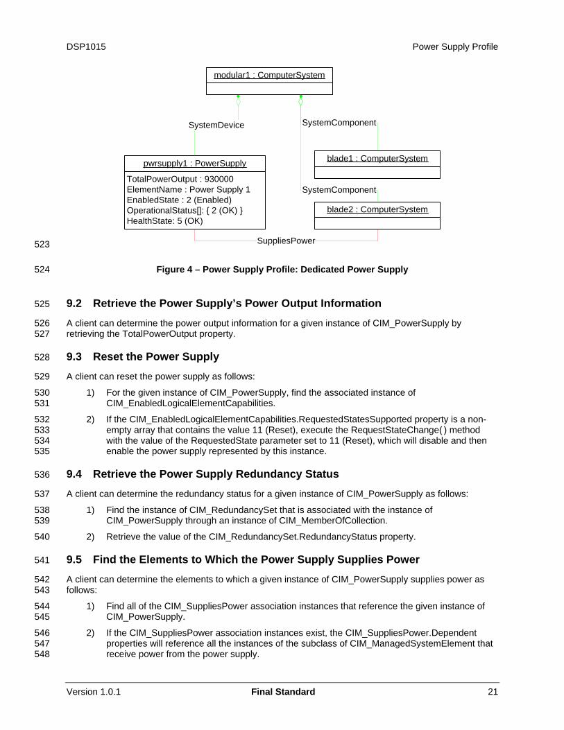
Realizes
ReferencedProfile
ElementConformsToProfile
SystemDevice
ElementCapabilities
profile2 : RegisteredProfile
RegisteredName : Power SupplyRegisteredVersion : 1.0.0
profile1 : RegisteredProfile
RegisteredName : Base ServerRegisteredVersion : 1.0.0
capabilities1 : EnabledLogicalElementCapabilities
RequestedStatesSupported[ ] : {2 (Enabled),3 (Disabled)}
system1 : ComputerSystem
498
499
500 501 502 503 504 505 506
Figure 2 – Power Supply Profile: Object Diagram
Figure 3 represents a possible instantiation of the Power Supply Profile with redundancy. system1 has spare power supply redundancy. Because pwrsupply1 is associated with redundancyset1 through the CIM_IsSpare association, and the value of the pwrsupply1’s EnabledState property is 6 (Enabled but Offline), the pwrsupply1 is a Spare Power Supply that is enabled but is not actively providing power to system1. pwrsupply2 is the active power supply of system1 because the value of its EnabledState property is 2 (Enabled) and pwrsupply2 is associated with redundancyset1 only through the CIM_MemberOfCollection association.
Version 1.0.1 Final Standard 19
Power Supply Profile DSP1015
507 508
509 510 511 512 513 514 515
If redundancyset1 supports the Failover( ) method, a client can execute the Failover( ) method with the FailoverFrom parameter referencing pwrsupply2 and the FailoverTo parameter referencing pwrsupply1.
When the Failover( ) method executes successfully, pwrsupply1 will be the active power supply for system1 with an EnabledState property value of 2 (Enabled) and will not be associated with redundancyset1 through the CIM_IsSpare association. Additionally, pwrsupply2 will not have an EnabledState property value of 2 (Enabled) and will be associated to redundancyset1 through the CIM_IsSpare association. Because pwrsupply1 and pwrsupply2 do not have the CIM_SuppliesPower association reference, both are supplying power to system1, which is denoted by the CIM_SystemDevice association.
system1 : ComputerSystem
pwrsupply2 : PowerSupply
TotalPowerOutput : 930000ElementName : Power Supply 2EnabledState : 2 (Enabled)OperationalStatus[]: { 2 (OK) }HealthState: 5 (OK)
redundancyset1 : RedundancySet
InstanceID : XYZ : Power Supply Redundancy 1RedundancyStatus : RedundantTypeOfSet[] : { 4 (Sparing)}
SystemDevice
pwrsupply1 : PowerSupply
TotalPowerOutput : 930000ElementName : Power Supply 1EnabledState : 6 (Enabled but Offline)OperationalStatus[]: { 2 (OK) }HealthState: 5 (OK)
MemberOfCollection
MemberOfCollectionIsSpare
SpareStatus : 2 (Hot Standby)FailoverSupported : 4 (Both Manual and
Automatic)
SystemDevice
OwningCollectionElement
516
517
518 519 520 521 522
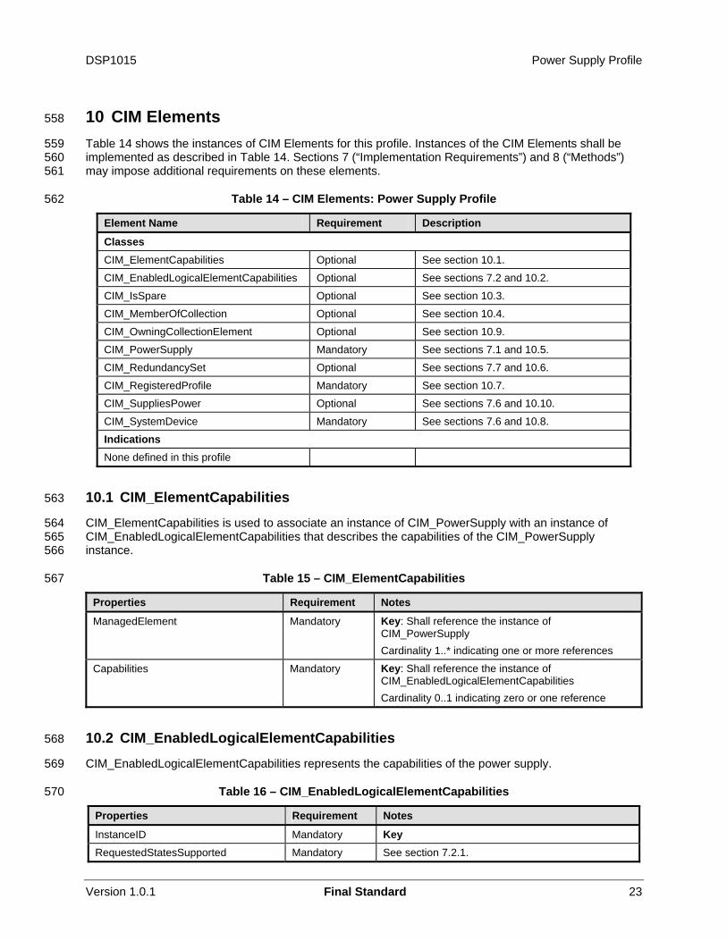
Figure 3 – Power Supply Profile: Redundancy Object Diagram
Figure 4 shows a possible instantiation of the Power Supply Profile in which the power supply is dedicated to supply power to a particular managed element. In this diagram, pwrsupply1 is associated to blade2 through the CIM_SuppliesPower association. This association denotes that pwrsupply1 supplies power only to blade2 and does not supply power to modular1 and blade1. In this case, the CIM_SystemDevice association does not reference the element to which pwrsupply1 supplies power.
20 Final Standard Version 1.0.1
DSP1015 Power Supply Profile
modular1 : ComputerSystem
pwrsupply1 : PowerSupply
TotalPowerOutput : 930000ElementName : Power Supply 1EnabledState : 2 (Enabled)OperationalStatus[]: { 2 (OK) }HealthState: 5 (OK)
SystemDevice
blade1 : ComputerSystem
SystemComponent
blade2 : ComputerSystem
SystemComponent
SuppliesPower 523
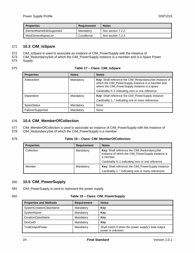
524
525
526 527
528
529
530 531
532 533 534 535
536
537
538 539
540
541
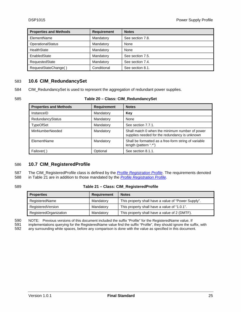
542 543
544 545
546 547 548
Figure 4 – Power Supply Profile: Dedicated Power Supply
9.2 Retrieve the Power Supply’s Power Output Information
A client can determine the power output information for a given instance of CIM_PowerSupply by retrieving the TotalPowerOutput property.
9.3 Reset the Power Supply
A client can reset the power supply as follows:
1) For the given instance of CIM_PowerSupply, find the associated instance of CIM_EnabledLogicalElementCapabilities.
2) If the CIM_EnabledLogicalElementCapabilities.RequestedStatesSupported property is a non-empty array that contains the value 11 (Reset), execute the RequestStateChange( ) method with the value of the RequestedState parameter set to 11 (Reset), which will disable and then enable the power supply represented by this instance.
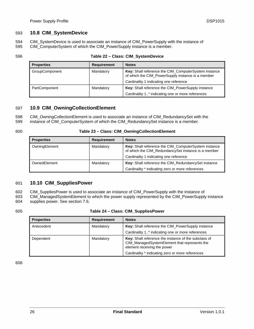
9.4 Retrieve the Power Supply Redundancy Status
A client can determine the redundancy status for a given instance of CIM_PowerSupply as follows:
1) Find the instance of CIM_RedundancySet that is associated with the instance of CIM_PowerSupply through an instance of CIM_MemberOfCollection.
2) Retrieve the value of the CIM_RedundancySet.RedundancyStatus property.
9.5 Find the Elements to Which the Power Supply Supplies Power
A client can determine the elements to which a given instance of CIM_PowerSupply supplies power as follows:
1) Find all of the CIM_SuppliesPower association instances that reference the given instance of CIM_PowerSupply.
2) If the CIM_SuppliesPower association instances exist, the CIM_SuppliesPower.Dependent properties will reference all the instances of the subclass of CIM_ManagedSystemElement that receive power from the power supply.
Version 1.0.1 Final Standard 21
Power Supply Profile DSP1015
22 Final Standard Version 1.0.1
3) If no CIM_SuppliesPower association instances exist, select the CIM_ComputerSystem instance associated with the given instance of the CIM_PowerSupply instance through the CIM_SystemDevice association.
549 550 551
552
553
554 555
556 557
9.6 Determine Whether the CIM_PowerSupply.ElementName Is Modifiable
A client can determine whether it can modify the CIM_PowerSupply.ElementName property as follows:
1) Find the CIM_EnabledLogicalElementCapabilities instance that is associated with the CIM_PowerSupply instance.
2) Query the value of the ElementNameEditSupported property of the instance. If the value is TRUE, the client can modify the CIM_PowerSupply.ElementName property.
DSP1015 Power Supply Profile
Version 1.0.1 Final Standard 23
10 CIM Elements 558
559 560 561
562
Table 14 shows the instances of CIM Elements for this profile. Instances of the CIM Elements shall be implemented as described in Table 14. Sections 7 (“Implementation Requirements”) and 8 (“Methods”) may impose additional requirements on these elements.
Table 14 – CIM Elements: Power Supply Profile
Element Name Requirement Description
Classes CIM_ElementCapabilities Optional See section 10.1.
CIM_EnabledLogicalElementCapabilities Optional See sections 7.2 and 10.2.
CIM_IsSpare Optional See section 10.3.
CIM_MemberOfCollection Optional See section 10.4.
CIM_OwningCollectionElement Optional See section 10.9.
CIM_PowerSupply Mandatory See sections 7.1 and 10.5.
CIM_RedundancySet Optional See sections 7.7 and 10.6.
CIM_RegisteredProfile Mandatory See section 10.7.
CIM_SuppliesPower Optional See sections 7.6 and 10.10.
CIM_SystemDevice Mandatory See sections 7.6 and 10.8.
Indications None defined in this profile
10.1 CIM_ElementCapabilities 563
564 565 566
567
CIM_ElementCapabilities is used to associate an instance of CIM_PowerSupply with an instance of CIM_EnabledLogicalElementCapabilities that describes the capabilities of the CIM_PowerSupply instance.
Table 15 – CIM_ElementCapabilities
Properties Requirement Notes
ManagedElement Mandatory Key: Shall reference the instance of CIM_PowerSupply Cardinality 1..* indicating one or more references
Capabilities Mandatory Key: Shall reference the instance of CIM_EnabledLogicalElementCapabilities Cardinality 0..1 indicating zero or one reference
10.2 CIM_EnabledLogicalElementCapabilities 568
569
570
CIM_EnabledLogicalElementCapabilities represents the capabilities of the power supply.
Table 16 – CIM_EnabledLogicalElementCapabilities
Properties Requirement Notes
InstanceID Mandatory Key RequestedStatesSupported Mandatory See section 7.2.1.
Power Supply Profile DSP1015
24 Final Standard Version 1.0.1
Properties Requirement Notes
ElementNameEditSupported Mandatory See section 7.2.2.
MaxElementNameLen Conditional See section 7.2.3.
10.3 CIM_IsSpare 571
572 573 574
575
CIM_IsSpare is used to associate an instance of CIM_PowerSupply with the instance of CIM_RedundancySet of which the CIM_PowerSupply instance is a member and is a Spare Power Supply.
Table 17 – Class: CIM_IsSpare
Properties Notes Notes
Antecedent Mandatory Key: Shall reference the CIM_RedundancySet instance of which the CIM_PowerSupply instance is a member and where the CIM_PowerSupply instance is a spare Cardinality 0..1 indicating zero or one reference
Dependent Mandatory Key: Shall reference the CIM_PowerSupply instance Cardinality 1..* indicating one or more references
SpareStatus Mandatory None
FailoverSupported Mandatory None
10.4 CIM_MemberOfCollection 576
577 578
579
CIM_MemberOfCollection is used to associate an instance of CIM_PowerSupply with the instance of CIM_RedundancySet of which the CIM_PowerSupply is a member.
Table 18 – Class: CIM_MemberOfCollection
Properties Requirement Notes
Collection Mandatory Key: Shall reference the CIM_RedundancySet instance of which the CIM_PowerSupply instance is a member. Cardinality 0..1 indicating zero or one reference
Member Mandatory Key: Shall reference the CIM_PowerSupply instance Cardinality 1..* indicating one or many references
10.5 CIM_PowerSupply 580
581
582
CIM_PowerSupply is used to represent the power supply.
Table 19 – Class: CIM_PowerSupply
Properties and Methods Requirement Notes
SystemCreationClassName Mandatory Key SystemName Mandatory Key CreationClassName Mandatory Key DeviceID Mandatory Key TotalOutputPower Mandatory Shall match 0 when the power supply’s total output
power is unknown
DSP1015 Power Supply Profile
Version 1.0.1 Final Standard 25
Properties and Methods Requirement Notes
ElementName Mandatory See section 7.8.
OperationalStatus Mandatory None
HealthState Mandatory None
EnabledState Mandatory See section 7.5.
RequestedState Mandatory See section 7.4.
RequestStateChange( ) Conditional See section 8.1.
10.6 CIM_RedundancySet 583
584
585
CIM_RedundancySet is used to represent the aggregation of redundant power supplies.
Table 20 – Class: CIM_RedundancySet
Properties and Methods Requirement Notes
InstanceID Mandatory Key RedundancyStatus Mandatory None
TypeOfSet Mandatory See section 7.7.1.
MinNumberNeeded Mandatory Shall match 0 when the minimum number of power supplies needed for the redundancy is unknown
ElementName Mandatory Shall be formatted as a free-form string of variable length (pattern “.*”)
Failover( ) Optional See section 8.1.1.
10.7 CIM_RegisteredProfile 586
The CIM_RegisteredProfile class is defined by the Profile Registration Profile. The requirements denoted in
587 Table 21 are in addition to those mandated by the Profile Registration Profile. 588
589 Table 21 – Class: CIM_RegisteredProfile
Properties Requirement Notes
RegisteredName Mandatory This property shall have a value of “Power Supply”. RegisteredVersion Mandatory This property shall have a value of “1.0.1”.
RegisteredOrganization Mandatory This property shall have a value of 2 (DMTF).
NOTE: Previous versions of this document included the suffix “Profile” for the RegisteredName value. If implementations querying for the RegisteredName value find the suffix “Profile”, they should ignore the suffix, with any surrounding white spaces, before any comparison is done with the value as specified in this document.
590 591 592
Power Supply Profile DSP1015
26 Final Standard Version 1.0.1
10.8 CIM_SystemDevice 593
594 595
596
CIM_SystemDevice is used to associate an instance of CIM_PowerSupply with the instance of CIM_ComputerSystem of which the CIM_PowerSupply instance is a member.
Table 22 – Class: CIM_SystemDevice
Properties Requirement Notes
GroupComponent Mandatory Key: Shall reference the CIM_ComputerSystem instance of which the CIM_PowerSupply instance is a member Cardinality 1 indicating one reference
PartComponent Mandatory Key: Shall reference the CIM_PowerSupply instance Cardinality 1..* indicating one or more references
10.9 CIM_OwningCollectionElement 597
598 599
600
CIM_OwningCollectionElement is used to associate an instance of CIM_RedundancySet with the instance of CIM_ComputerSystem of which the CIM_RedundancySet instance is a member.
Table 23 – Class: CIM_OwningCollectionElement
Properties Requirement Notes
OwningElement Mandatory Key: Shall reference the CIM_ComputerSystem instance of which the CIM_RedundancySet instance is a member Cardinality 1 indicating one reference
OwnedElement Mandatory Key: Shall reference the CIM_RedundancySet instance Cardinality * indicating zero or more references
10.10 CIM_SuppliesPower 601
602 603 604
605
CIM_SuppliesPower is used to associate an instance of CIM_PowerSupply with the instance of CIM_ManagedSystemElement to which the power supply represented by the CIM_PowerSupply instance supplies power. See section 7.6.
Table 24 – Class: CIM_SuppliesPower
Properties Requirement Notes
Antecedent Mandatory Key: Shall reference the CIM_PowerSupply instance Cardinality 1..* indicating one or more references
Dependent Mandatory Key: Shall reference the instance of the subclass of CIM_ManagedSystemElement that represents the element receiving the power Cardinality * indicating zero or more references
606
DSP1015 Power Supply Profile
Version 1.0.1 Final Standard 27
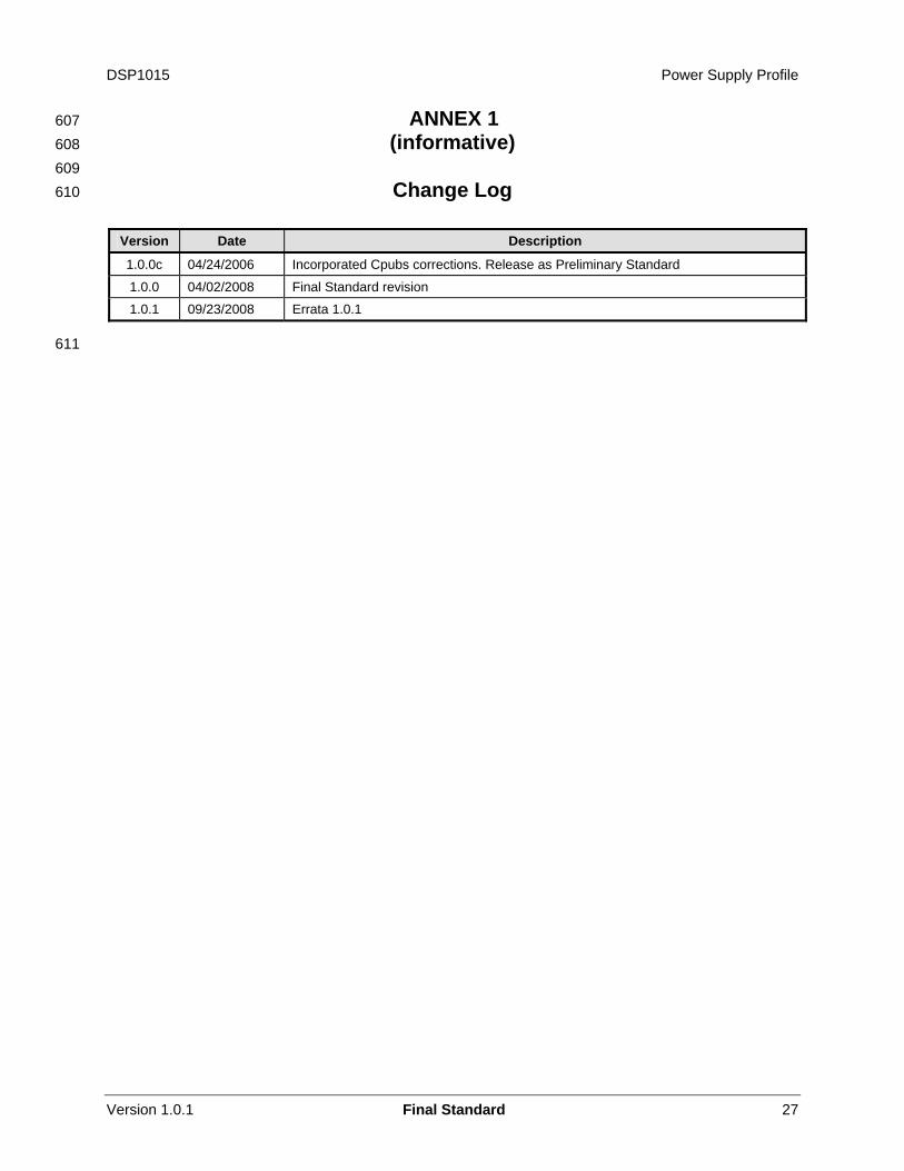
ANNEX 1 (informative)
Change Log
607 608 609 610
Version Date Description
1.0.0c 04/24/2006 Incorporated Cpubs corrections. Release as Preliminary Standard
1.0.0 04/02/2008 Final Standard revision
1.0.1 09/23/2008 Errata 1.0.1
611
Power Supply Profile DSP1015
28 Final Standard Version 1.0.1
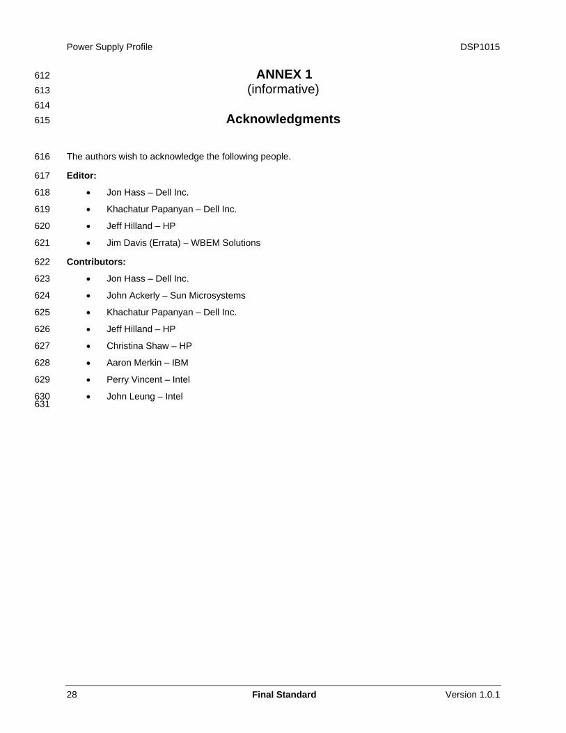
ANNEX 1 (informative)
Acknowledgments
612 613 614 615
616
617
618
619
620
621
622
623
624
625
626
627
628
629
630 631
The authors wish to acknowledge the following people.
Editor:
• Jon Hass – Dell Inc.
• Khachatur Papanyan – Dell Inc.
• Jeff Hilland – HP
• Jim Davis (Errata) – WBEM Solutions
Contributors:
• Jon Hass – Dell Inc.
• John Ackerly – Sun Microsystems
• Khachatur Papanyan – Dell Inc.
• Jeff Hilland – HP
• Christina Shaw – HP
• Aaron Merkin – IBM
• Perry Vincent – Intel
• John Leung – Intel