Embed Size (px)
Citation preview
Alberta Power Industry Consortium & University of Alberta
Professional Development Course
Power System Grounding – Industry Experiences
Organized By
Alberta Power Industry Consortium & University of Alberta AESO AltaLink ATCO Enmax Epcor FortisAlberta
Instructed By
Joseph Kuffar & Dennis Peters, Enmax Nerkez Lalic, Epcor
Dennis Rasmusson, AltaLink Wilsun Xu, University of Alberta
May 28 & 30, 2013
Calgary & Edmonton, Alberta, Canada

1
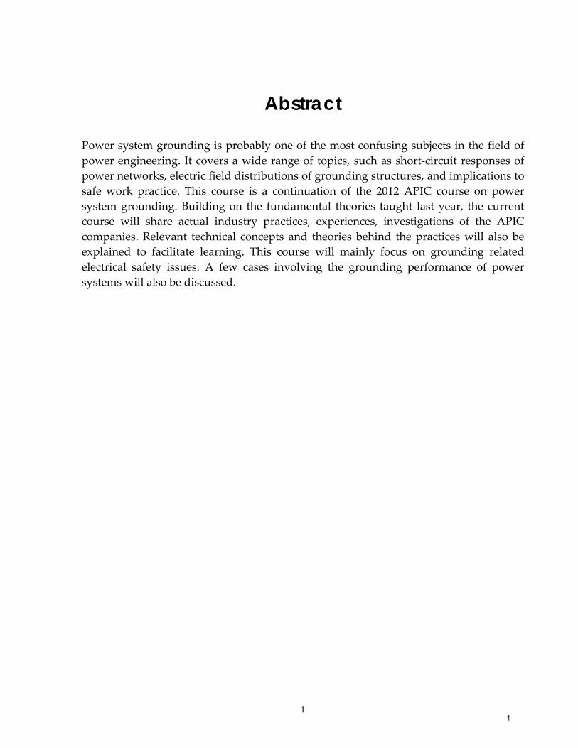
Abstract
Power system grounding is probably one of the most confusing subjects in the field of
power engineering. It covers a wide range of topics, such as short‐circuit responses of
power networks, electric field distributions of grounding structures, and implications to
safe work practice. This course is a continuation of the 2012 APIC course on power
system grounding. Building on the fundamental theories taught last year, the current
course will share actual industry practices, experiences, investigations of the APIC
companies. Relevant technical concepts and theories behind the practices will also be
explained to facilitate learning. This course will mainly focus on grounding related
electrical safety issues. A few cases involving the grounding performance of power
systems will also be discussed.
1
2
Confidentiality Requirement
This course material was prepared by the University of Alberta for the ultimate benefit of the Alberta Power Industry Consortium members (hereinafter called “SPONSORS”). It may contain confidential research findings, trade secrets, proprietary materials (collectively called “Proprietary Information”). The term Proprietary Information includes, but is not limited to, plans, drawings, designs, specifications, new teaching materials, trade secrets, processes, systems, manufacturing techniques, model and mock-ups, and financial or cost data.
The document is made available to the sponsors only. The Sponsors will use all reasonable efforts to treat and keep confidential, and cause its officers, members, directors, employees, agents, contractors and students, if any, (“Representatives”) to treat and keep confidential, and Proprietary Information in the document and the document itself. This course material shall not be disclosed to any third party without the consent of the Alberta Power Industry Consortium.
Disclaimer
This document may contain reports, guidelines, practices that are developed by the University of Alberta and the members of the Alberta Power Industry Consortium (APIC).
Neither the APIC members, the University of Alberta, nor any of other person acting on his/her behalf makes any warranty or implied, or assumes any legal responsibility for the accuracy of any information or for the completeness or usefulness of any apparatus, product or process disclosed, or accept liability for the use, or damages resulting from the use, thereof. Neither do they represent that their use would not infringe upon privately owned rights.
Furthermore, the APIC companies and the University of Alberta hereby disclaim any and all warranties, expressed or implied, including the warranties of merchantability and fitness for a particular purpose, whether arising by law, custom, or conduct, with respect to any of the information contained in this document. In no event shall the APIC companies and the University of Alberta be liable for incidental or consequential damages because of use or any information contained in this document.
Any reference in this document to any specific commercial product, process or service by trade name, trademark, manufacture, or otherwise does not necessarily constitute or imply its endorsement or recommendation by the University of Alberta and/or the APIC companies.
2
3
About the Alberta Power Industry Consortium:
The Alberta Power Industry Consortium consists of six Alberta utility companies (AESO,
AltaLink, ATCO, Enmax, Epcor and FortisAlberta) and the University of Alberta. Established in
the fall of 2007, its goal is to bring Alberta power companies together, with the University of
Alberta as the coordinating organization, to solve technical problems of common interest, to
produce more power engineering graduates, to support the professional development of
current employees, and to promote technical cooperation and exchange in Alberta’s power
utility community.
3
4
About the instructors:
Mr. Joseph Kuffar is a 2004 graduate of Electrical Engineering from the University of Saskatchewan.
Joseph has 9 years technical engineering experience. His work experience includes system planning,
distribution system design, material standards and QC, and asset management (distribution &
network). He is currently holds a position with ENMAX as Supervising Engineer, T&D Asset
Management. Joseph is a registered professional engineer in the province of Alberta.
Mr. Nerkez Lalic is a 1972 graduate of Electric Power Engineering Faculty from the University of
Sarajevo, Bosnia & Herzegovina. He worked for international equipment manufacturing,
engineering and consulting companies on the design, construction, testing, commissioning and EPC
management of high voltage substation and overhead/underground transmission line projects. He
has been with EPCOR for nine years and currently holds the position of Senior Manager,
Transmission Projects. Mr. Lalic has a special interest in improving EPC processes of complex
engineering projects, focusing on implementation of COAA standardized engineering contracts in
practice and safety standards improvement, coordination and implementation during execution of
complex construction works. Mr. Lalic is a registered professional engineer in the province of
Alberta.
Mr. Dennis Peters is a 2008 graduate of Electrical Engineering from the University of Saskatchewan.
Dennis worked for ENMAX upon graduation and has 5 years of engineering experience. His work
experience includes network secondary distribution customer and system design and recently
network and distribution asset management. He has special interest in network secondary
distribution material specifications and material QC and QA. Dennis currently holds a position with
ENMAX as T&D Asset Management Engineer. Dennis is a registered professional engineer in the
province of Alberta.
Mr. Dennis Rasmusson is a 1972 graduate of Electrical Engineering Technology from NAIT in
Edmonton. Upon graduation Dennis spent the first 10 year of his career in the field in the area of
protection and control. He spent the next 17 years in various positions in management in both
transmission and distribution. During this time his roles included Manager of Substation
Construction and Operations, Regional Transmission Maintenance Manager, Area Manager of
Sherwood Park, and Director of Asset Management. During the last 15 years his main focus was on
safety and held roles of Safety Manager and Director of EH&S. He has been working in the
electrical utility industry for 42 years. In 2010 Dennis started his retirement by working as a safety
specialist on a reduced work week and plans on retiring late 2013.
Dr. Wilsun Xu obtained a B.Sc. degree from China in 1982 and PhD from UBC in 1989. He worked
in BC Hydro from 1989 to 1996. He joined the University of Alberta as a faculty member in 1996 and
is currently a research chair professor at the U of A. Dr. Xu has extensive engineering and research
experiences in the area of power quality. His research work on multiphase power system analysis
has helped him to formulate a methodology to analyze faulted power systems with complex
grounding configurations. In recent years, Dr. Xu has used the methodology to investigate several
issues related to power system grounding. Dr. Xu is a registered professional engineer in the
province of Alberta.
4
5
Course Outline
1. Review: Basic concepts of power system grounding
Performance grounding versus safety grounding
Basics of safety grounding
Basics of performance grounding
2. Grounding and safe work practice
Theory: Equipotential bonding and grounding transmission lines
Case: Working on isolated transmission facilities – Altalink practice
Case: Deep grounding‐well method for improving Epcor substation
grounding
Theory: Characteristics of GPR as affected by grounding
arrangements
3. Grounding performance of power systems
Theory: measurement of grounding resistances
Case: Distribution grounding system assessment and replacement
program of Enmax
Case: Bonding feeder and substation neutrals – pros, cons, and ATCO
practice
Case: Does improving grounding help to reduce telephone
interference?
5
Alberta Power Industry Consortium & University of Alberta
Professional Development Course
by Wilsun Xu, Professor
[email protected] Department of Electrical & Computer Engineering
University of Alberta
May 2013
Power System Grounding - Industry Experiences
6
Background of this course
• The 2012 APIC course covered various concepts & theories of power system grounding;
• The course feedback indicates that there is an interest to learn actual cases and industry experiences on grounding;
• This course is developed as a continuation of the last year’s course, with a focus on industry applications and experiences;
• Key theories will also be reviewed to enhance learning;
• Industry speakers are invited to share their experiences
7
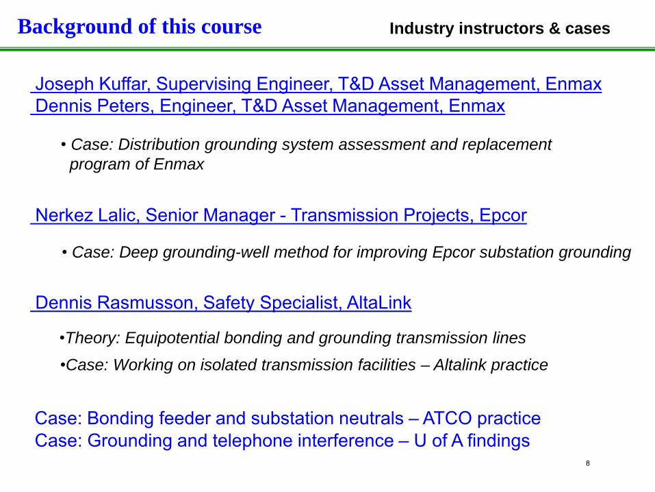
Background of this course Industry instructors & cases
Joseph Kuffar, Supervising Engineer, T&D Asset Management, Enmax Dennis Peters, Engineer, T&D Asset Management, Enmax Nerkez Lalic, Senior Manager - Transmission Projects, Epcor Dennis Rasmusson, Safety Specialist, AltaLink
•Theory: Equipotential bonding and grounding transmission lines •Case: Working on isolated transmission facilities – Altalink practice
• Case: Deep grounding-well method for improving Epcor substation grounding
• Case: Distribution grounding system assessment and replacement program of Enmax
Case: Bonding feeder and substation neutrals – ATCO practice Case: Grounding and telephone interference – U of A findings
8
Course Outline
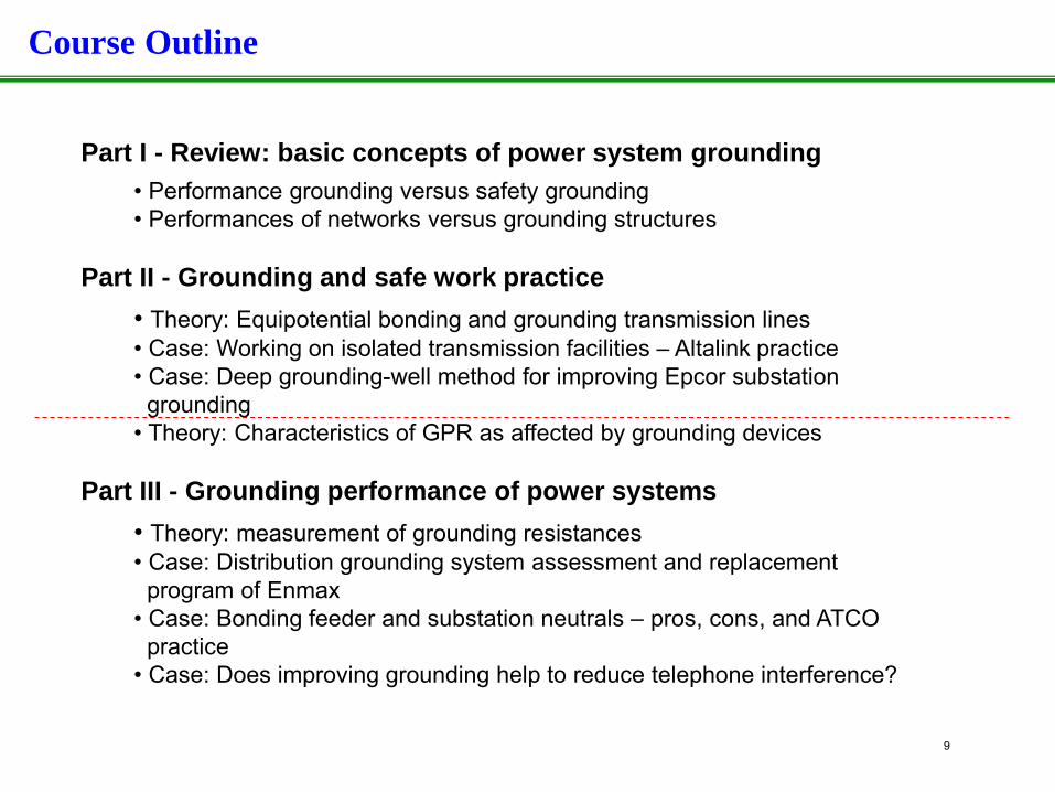
Part I - Review: basic concepts of power system grounding • Performance grounding versus safety grounding • Performances of networks versus grounding structures
Part II - Grounding and safe work practice
• Theory: Equipotential bonding and grounding transmission lines • Case: Working on isolated transmission facilities – Altalink practice • Case: Deep grounding-well method for improving Epcor substation grounding • Theory: Characteristics of GPR as affected by grounding devices
Part III - Grounding performance of power systems
• Theory: measurement of grounding resistances • Case: Distribution grounding system assessment and replacement program of Enmax • Case: Bonding feeder and substation neutrals – pros, cons, and ATCO practice • Case: Does improving grounding help to reduce telephone interference?
9
Part I
Quick Review of Last Year’s Material
• When performing short-circuit analysis, you encounter If-1ph>If-3ph. What does it mean? If this is a concern, what can you do?
• What is temporary overvoltage (TOV)? What is the impact of grounding on TOV?
• What is GPR and what is the profile or distribution of GPR?
• What is the step voltage?
• Why grounding through a feeder neutral is better than grounding through a temporary grounding rod?
10
1. Introduction
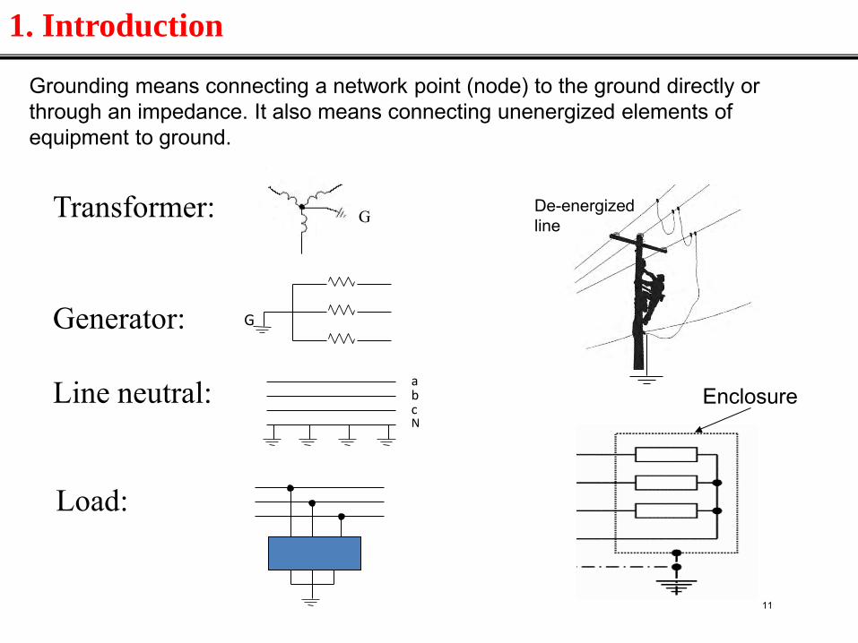
Transformer: Generator: Line neutral:
G
Load:
G
a b c N
Grounding means connecting a network point (node) to the ground directly or through an impedance. It also means connecting unenergized elements of equipment to ground.
Enclosure
De-energized line
11
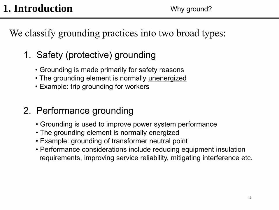
We classify grounding practices into two broad types:
1. Safety (protective) grounding
2. Performance grounding
• Grounding is made primarily for safety reasons • The grounding element is normally unenergized • Example: trip grounding for workers
• Grounding is used to improve power system performance • The grounding element is normally energized • Example: grounding of transformer neutral point • Performance considerations include reducing equipment insulation requirements, improving service reliability, mitigating interference etc.
1. Introduction Why ground?
12
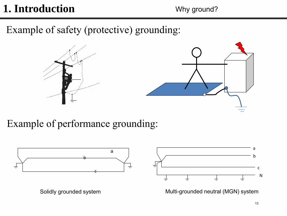
Example of safety (protective) grounding:
1. Introduction Why ground?
Example of performance grounding:
b
c
a
b
c
N
a
Solidly grounded system Multi-grounded neutral (MGN) system
13
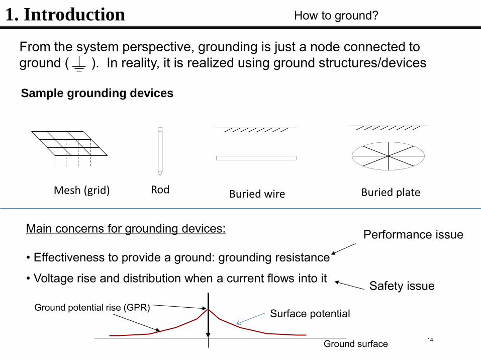
Mesh (grid) Rod Buried wire Buried plate
1. Introduction How to ground?
From the system perspective, grounding is just a node connected to ground ( ). In reality, it is realized using ground structures/devices
Sample grounding devices
Main concerns for grounding devices: • Effectiveness to provide a ground: grounding resistance
• Voltage rise and distribution when a current flows into it
Performance issue
Safety issue
Ground surface
Ground potential rise (GPR) Surface potential
14
1. Introduction
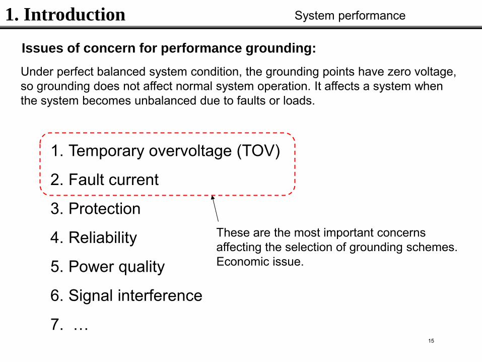
Issues of concern for performance grounding:
1. Temporary overvoltage (TOV)
2. Fault current
3. Protection
4. Reliability
5. Power quality
6. Signal interference
7. …
These are the most important concerns affecting the selection of grounding schemes. Economic issue.
Under perfect balanced system condition, the grounding points have zero voltage, so grounding does not affect normal system operation. It affects a system when the system becomes unbalanced due to faults or loads.
System performance
15
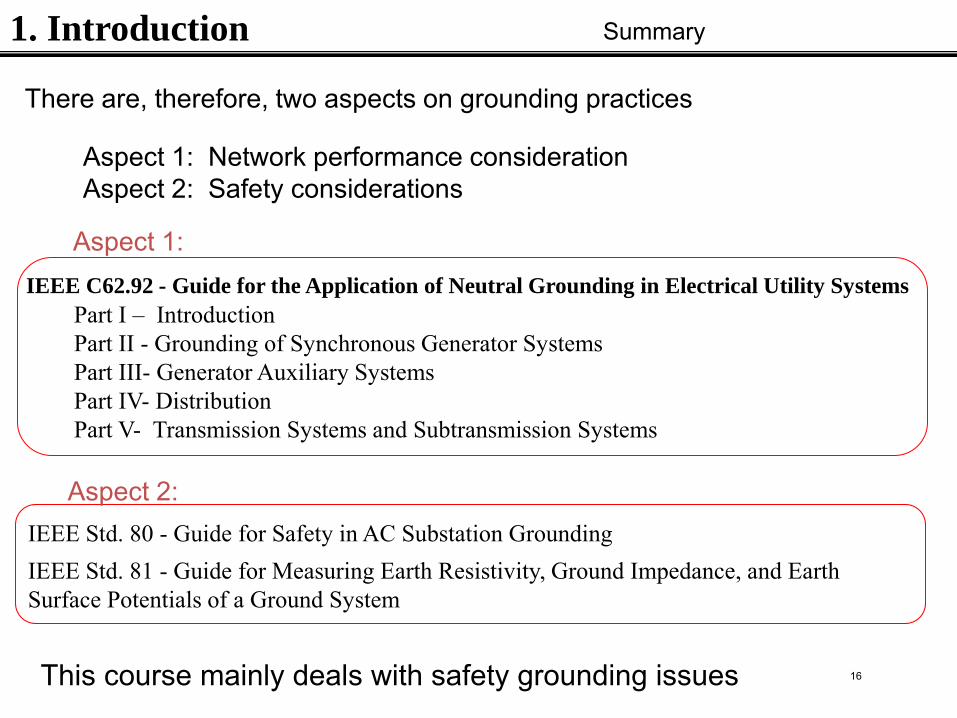
1. Introduction Summary
IEEE C62.92 - Guide for the Application of Neutral Grounding in Electrical Utility Systems Part I – Introduction Part II - Grounding of Synchronous Generator Systems Part III- Generator Auxiliary Systems Part IV- Distribution Part V- Transmission Systems and Subtransmission Systems
IEEE Std. 80 - Guide for Safety in AC Substation Grounding IEEE Std. 81 - Guide for Measuring Earth Resistivity, Ground Impedance, and Earth Surface Potentials of a Ground System
There are, therefore, two aspects on grounding practices
Aspect 1: Network performance consideration Aspect 2: Safety considerations
Aspect 1:
Aspect 2:
This course mainly deals with safety grounding issues 16
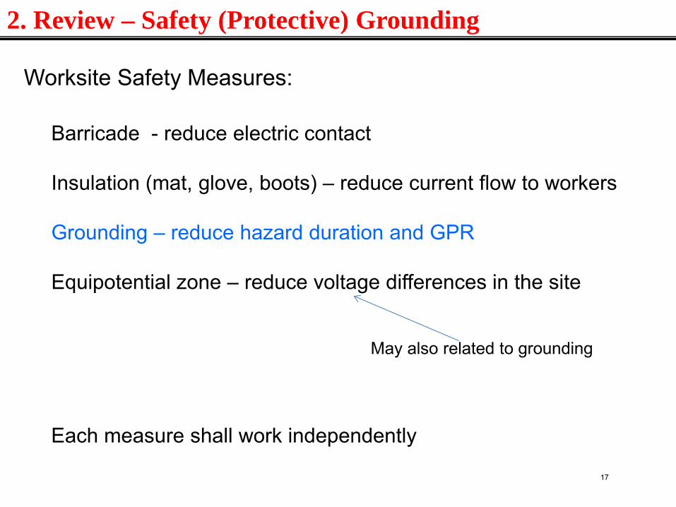
2. Review – Safety (Protective) Grounding
Worksite Safety Measures:
Barricade - reduce electric contact Insulation (mat, glove, boots) – reduce current flow to workers Grounding – reduce hazard duration and GPR Equipotential zone – reduce voltage differences in the site
May also related to grounding
Each measure shall work independently
17
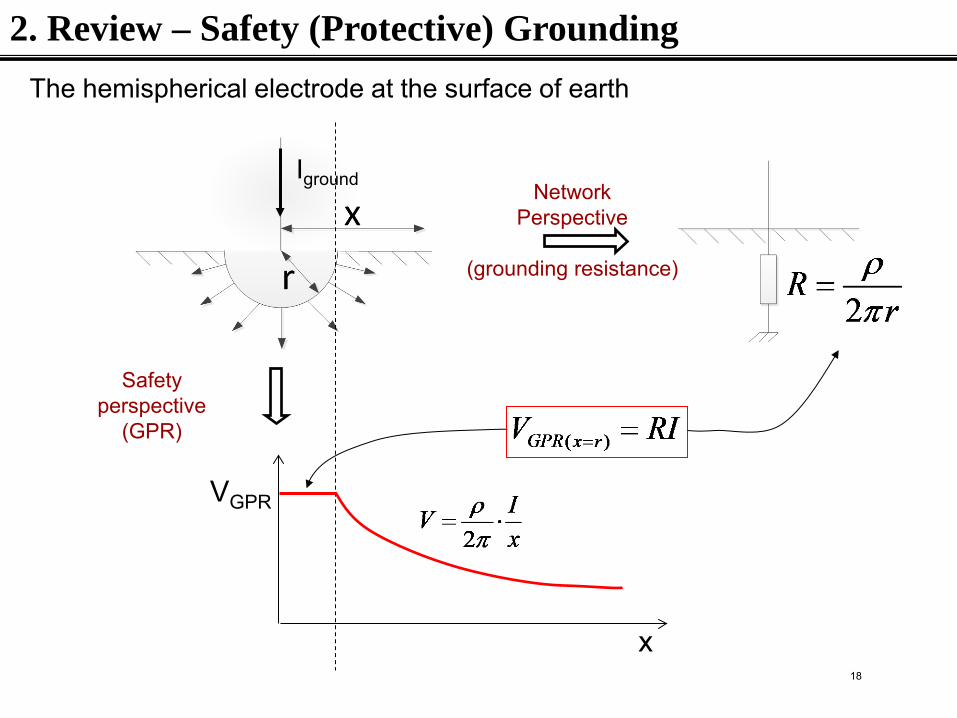
The hemispherical electrode at the surface of earth
Iground Network Perspective
(grounding resistance)
Safety perspective
(GPR)
2. Review – Safety (Protective) Grounding
x
VGPR
18
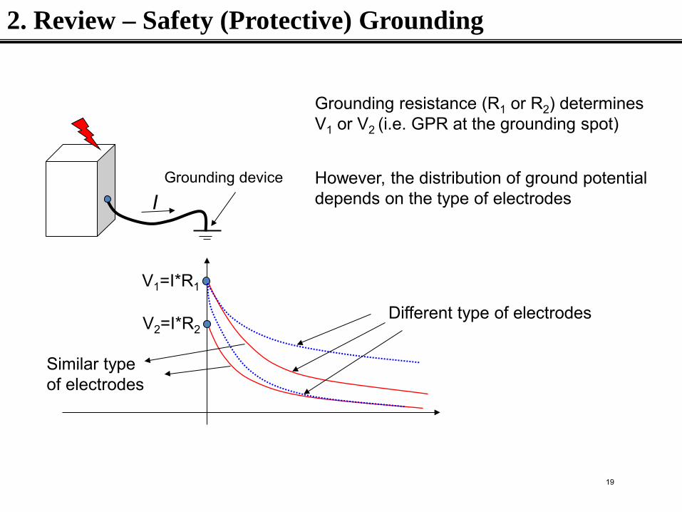
Grounding device
I
V1=I*R1
V2=I*R2
Grounding resistance (R1 or R2) determines V1 or V2 (i.e. GPR at the grounding spot)
However, the distribution of ground potential depends on the type of electrodes
Different type of electrodes
Similar type of electrodes
2. Review – Safety (Protective) Grounding
19
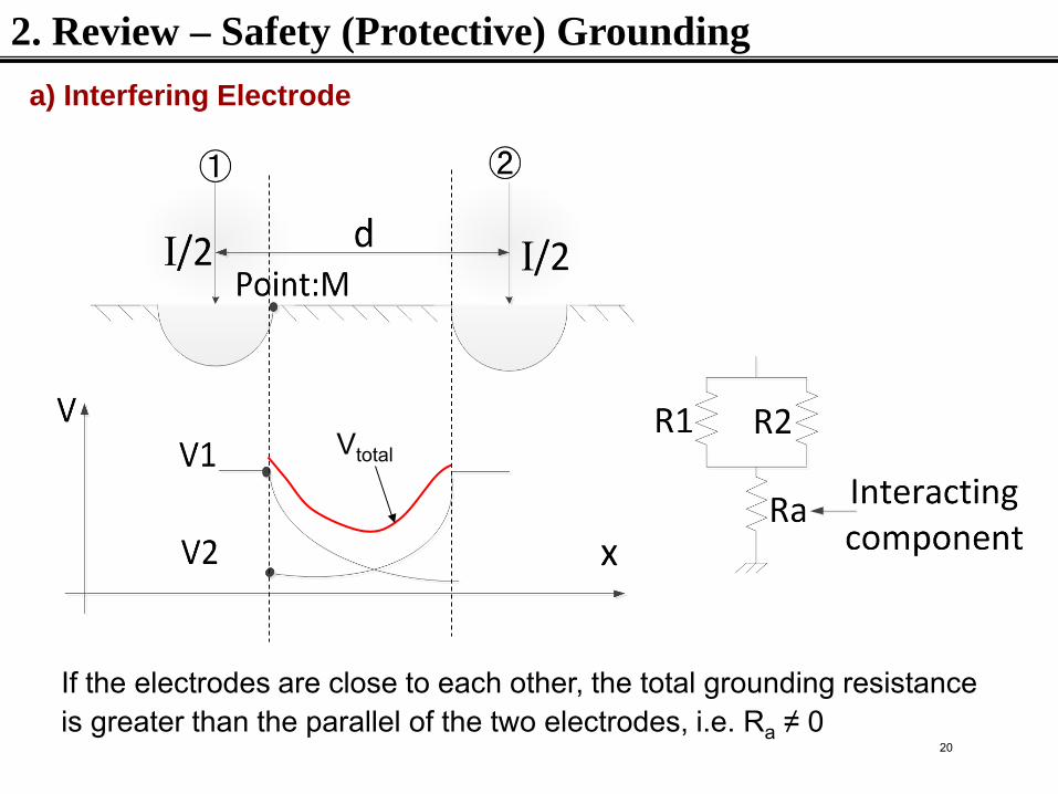
If the electrodes are close to each other, the total grounding resistance is greater than the parallel of the two electrodes, i.e. Ra ≠ 0
Vtotal
2. Review – Safety (Protective) Grounding
a) Interfering Electrode
20
1. Touch and step voltages 2. Electrical model of human body 3. Human response to electricity
2. Review – Safety (Protective) Grounding
Other important concepts:
These concepts will be reviewed in more detail in the next presentation
21
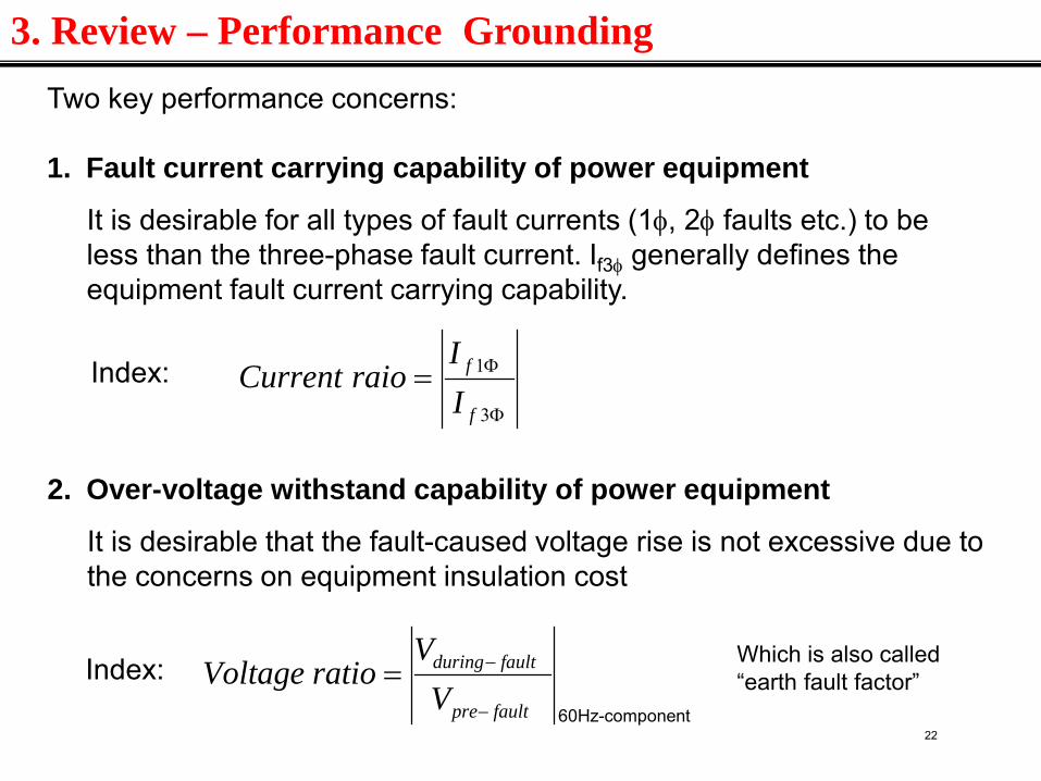
Two key performance concerns: 1. Fault current carrying capability of power equipment
It is desirable for all types of fault currents (1φ, 2φ faults etc.) to be less than the three-phase fault current. If3φ generally defines the equipment fault current carrying capability.
2. Over-voltage withstand capability of power equipment
It is desirable that the fault-caused voltage rise is not excessive due to the concerns on equipment insulation cost
Index: Φ
Φ=3
1
f
f
II
raioCurrent
Index: faultpre
faultduring
VV
ratioVoltage−
−=Which is also called “earth fault factor”
60Hz-component
3. Review – Performance Grounding
22
3.1 Impact of grounding
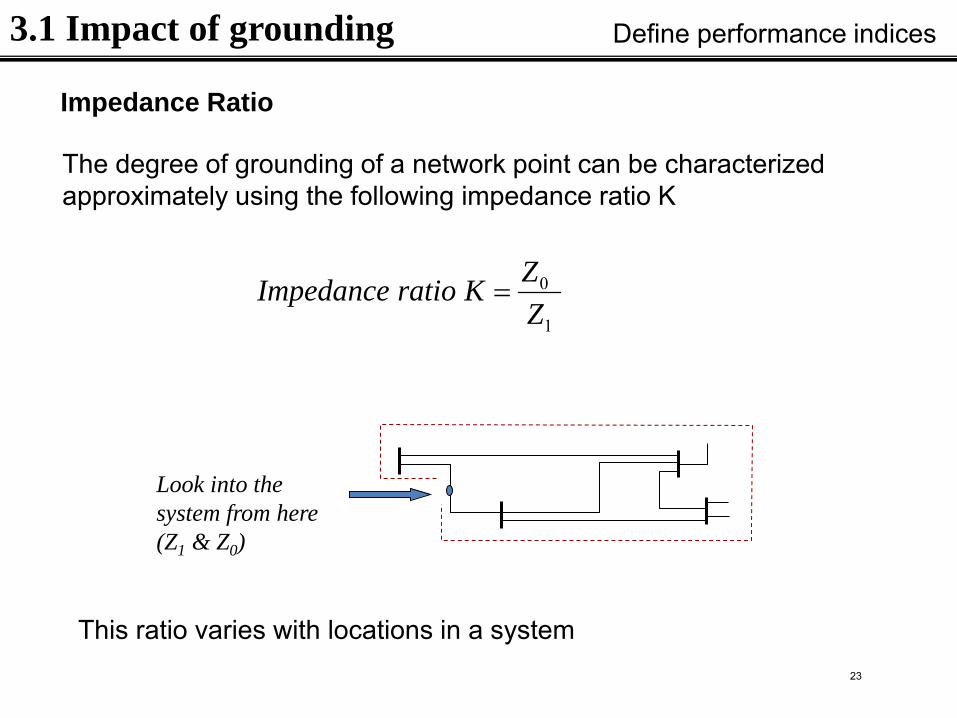
Impedance Ratio
The degree of grounding of a network point can be characterized approximately using the following impedance ratio K
Define performance indices
1
0
ZZKratioImpedance =
Look into the system from here (Z1 & Z0)
This ratio varies with locations in a system 23
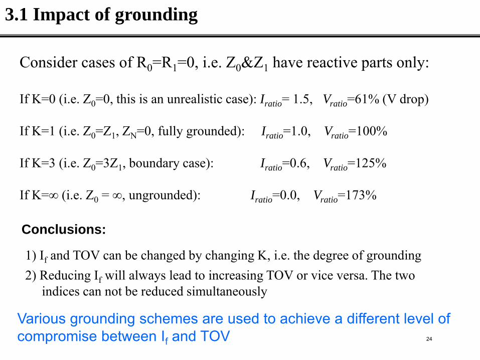
Consider cases of R0=R1=0, i.e. Z0&Z1 have reactive parts only: If K=0 (i.e. Z0=0, this is an unrealistic case): Iratio= 1.5, Vratio=61% (V drop) If K=1 (i.e. Z0=Z1, ZN=0, fully grounded): Iratio=1.0, Vratio=100% If K=3 (i.e. Z0=3Z1, boundary case): Iratio=0.6, Vratio=125% If K=∞ (i.e. Z0 = ∞, ungrounded): Iratio=0.0, Vratio=173%
Conclusions:
1) If and TOV can be changed by changing K, i.e. the degree of grounding 2) Reducing If will always lead to increasing TOV or vice versa. The two indices can not be reduced simultaneously
Various grounding schemes are used to achieve a different level of compromise between If and TOV
3.1 Impact of grounding
24
IEEE Definition
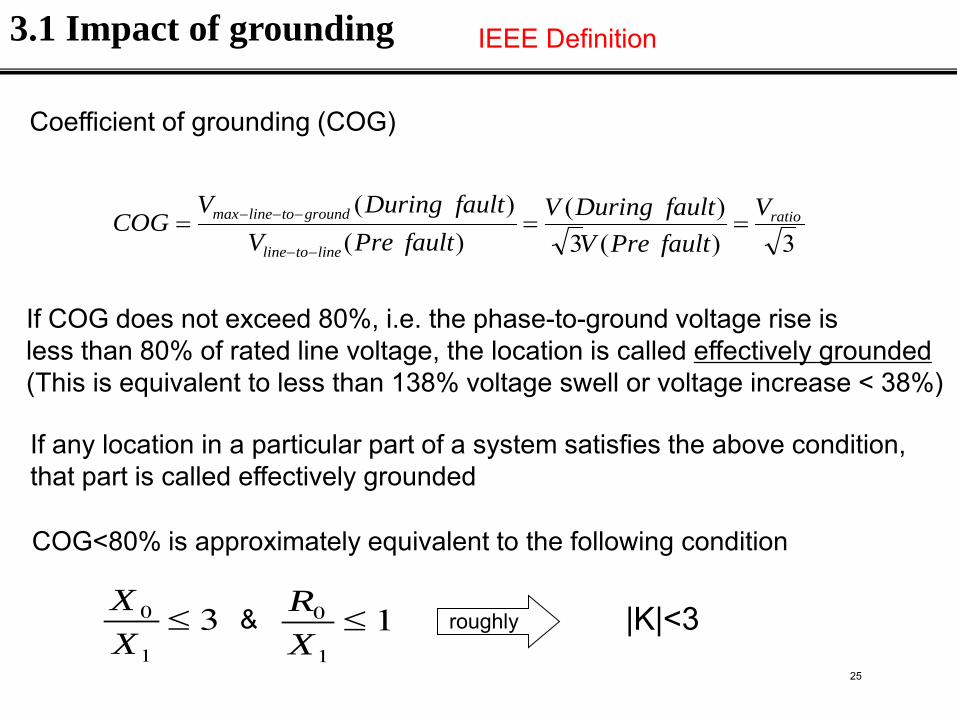
Coefficient of grounding (COG)
3)(3)(
)()( ratio
linetoline
groundtolinemax VfaultPreVfaultDuringV
faultPreVfaultDuringV
COG ===−−
−−−
If COG does not exceed 80%, i.e. the phase-to-ground voltage rise is less than 80% of rated line voltage, the location is called effectively grounded (This is equivalent to less than 138% voltage swell or voltage increase < 38%)
If any location in a particular part of a system satisfies the above condition, that part is called effectively grounded
31
0 ≤XX 1
1
0 ≤XR
COG<80% is approximately equivalent to the following condition
& |K|<3 roughly
3.1 Impact of grounding
25
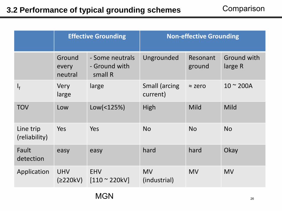
Effective Grounding Non-effective Grounding
Ground every neutral
- Some neutrals - Ground with small R
Ungrounded Resonant ground
Ground with large R
If Very large
large Small (arcing current)
≈ zero 10 ~ 200A
TOV Low Low(<125%) High Mild Mild
Line trip (reliability)
Yes Yes No No No
Fault detection
easy easy hard hard Okay
Application UHV (≥220kV)
EHV [110 ~ 220kV]
MV (industrial)
MV MV
MGN
3.2 Performance of typical grounding schemes Comparison
26
Equipotential Bonding and Grounding Transmission Lines
May, 2013 27

2
Welcome To Worker Protective Grounding Basics 28
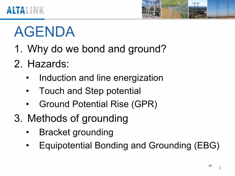
AGENDA 1. Why do we bond and ground? 2. Hazards:
• Induction and line energization • Touch and Step potential • Ground Potential Rise (GPR)
3. Methods of grounding • Bracket grounding • Equipotential Bonding and Grounding (EBG)
3
29
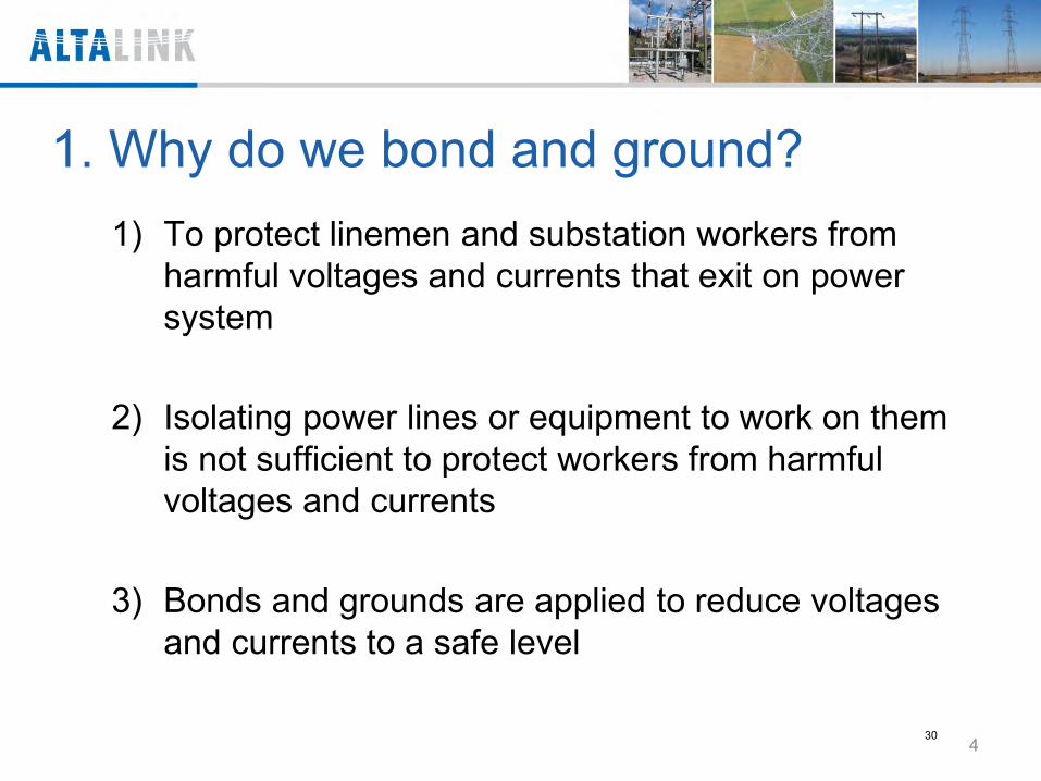
1. Why do we bond and ground? 1) To protect linemen and substation workers from
harmful voltages and currents that exit on power system
2) Isolating power lines or equipment to work on them is not sufficient to protect workers from harmful voltages and currents
3) Bonds and grounds are applied to reduce voltages and currents to a safe level
4 30
2. The Hazards
5 31
Range of Tolerable Current
Effects of an electric current passing through the vital parts of a human body depend on:
• Duration of the current flow, • Magnitude of the current flow, and • Frequency of this current
Ventricular fibrillation = immediate arrest of blood
circulation
6 32
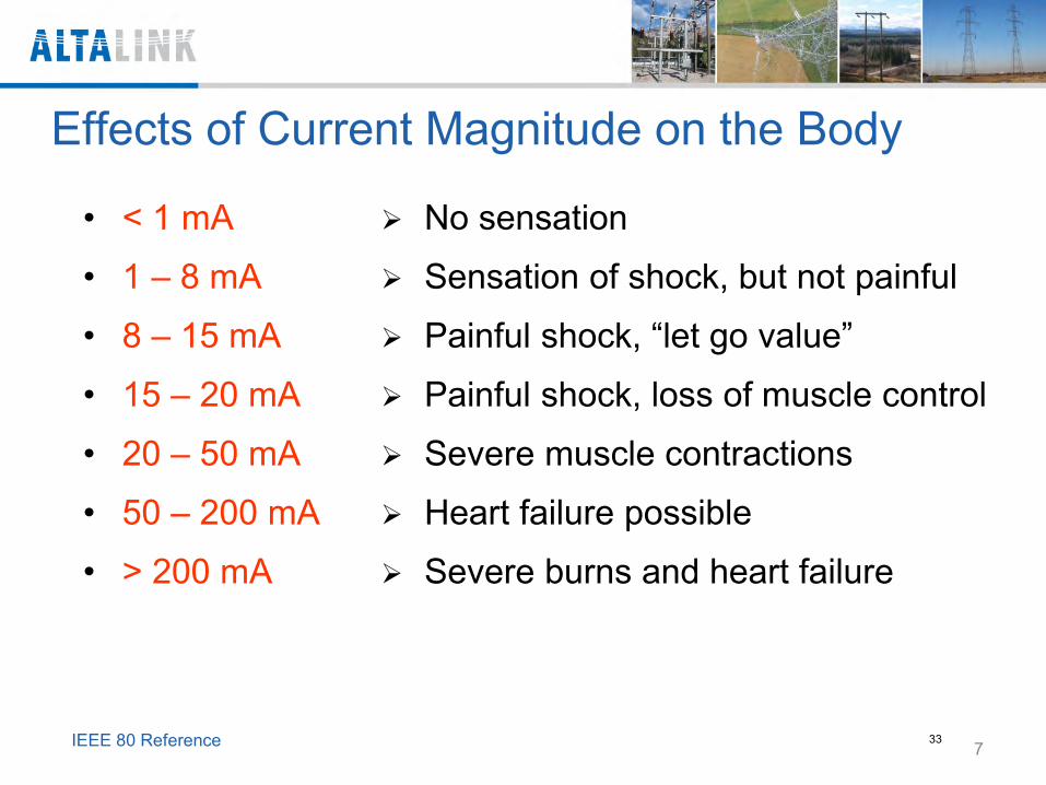
Effects of Current Magnitude on the Body
• < 1 mA
• 1 – 8 mA
• 8 – 15 mA
• 15 – 20 mA
• 20 – 50 mA
• 50 – 200 mA
• > 200 mA
No sensation
Sensation of shock, but not painful
Painful shock, “let go value”
Painful shock, loss of muscle control
Severe muscle contractions
Heart failure possible
Severe burns and heart failure
7 IEEE 80 Reference 33
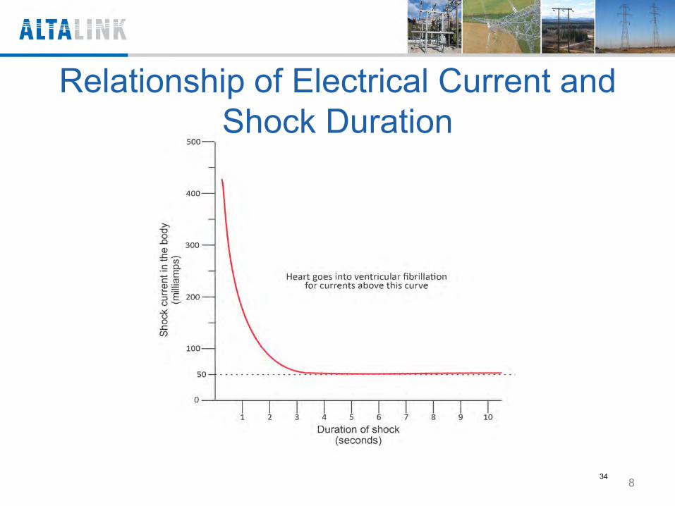
Relationship of Electrical Current and Shock Duration
8 34
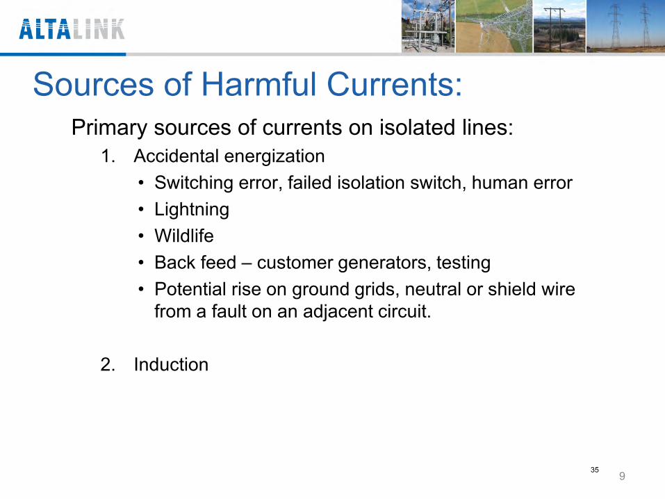
Sources of Harmful Currents: Primary sources of currents on isolated lines:
1. Accidental energization • Switching error, failed isolation switch, human error • Lightning • Wildlife • Back feed – customer generators, testing • Potential rise on ground grids, neutral or shield wire
from a fault on an adjacent circuit.
2. Induction
9 35
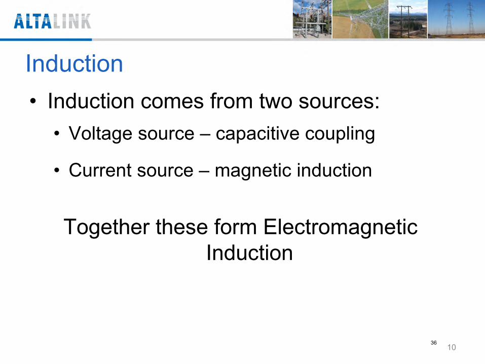
Induction • Induction comes from two sources:
• Voltage source – capacitive coupling
• Current source – magnetic induction Together these form Electromagnetic
Induction
10 36
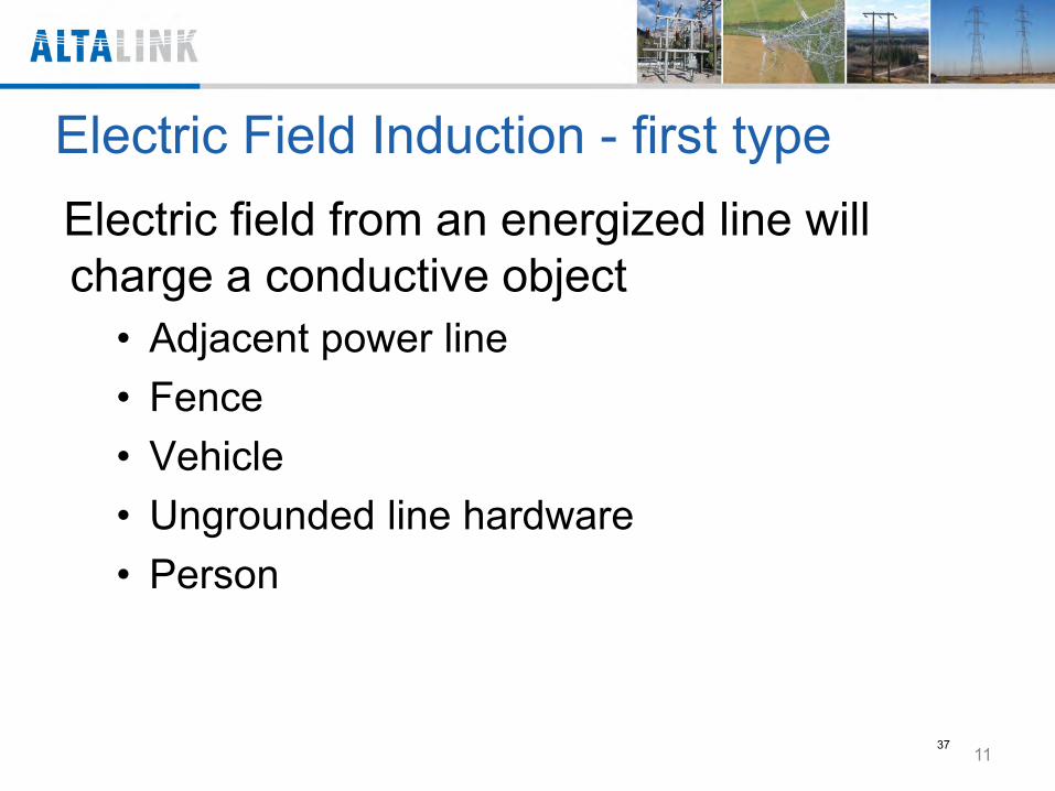
Electric Field Induction - first type Electric field from an energized line will charge a conductive object
• Adjacent power line • Fence • Vehicle • Ungrounded line hardware • Person
11 37
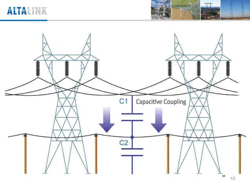
C1
C2
12 38
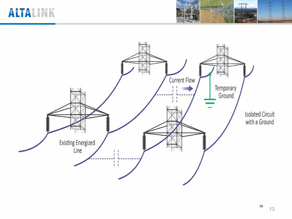
13 39
14 40
Magnetic Induction – second type • When there is a current flow in a conductor there will be
a magnetic field developed around that conductor • This magnetic field will expand and collapse at the
same frequency as the AC power system feeding the conductor
• When magnetic lines of force cut a conductor there will be a voltage produced in the isolated conductor Transformer action
15 41
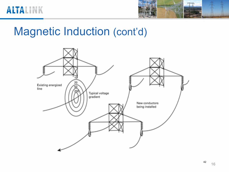
Magnetic Induction (cont’d)
16 42
Magnetic Induction (cont’d)
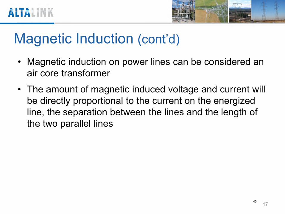
• Magnetic induction on power lines can be considered an air core transformer
• The amount of magnetic induced voltage and current will be directly proportional to the current on the energized line, the separation between the lines and the length of the two parallel lines
17 43
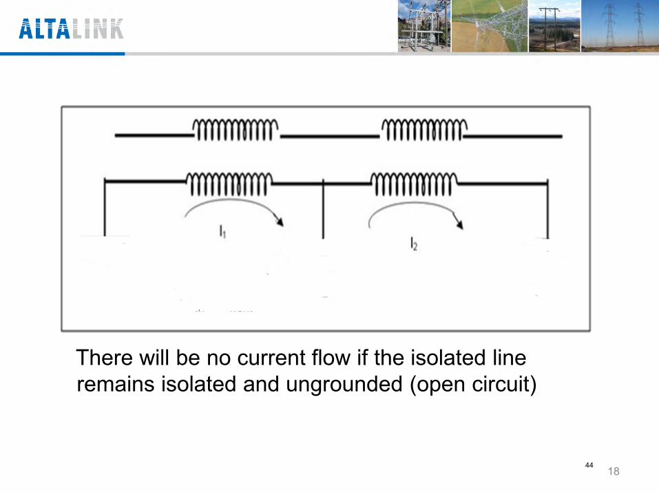
There will be no current flow if the isolated line remains isolated and ungrounded (open circuit)
18 44
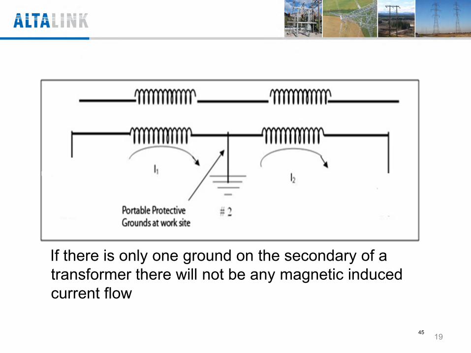
If there is only one ground on the secondary of a transformer there will not be any magnetic induced current flow
19 45
20 46
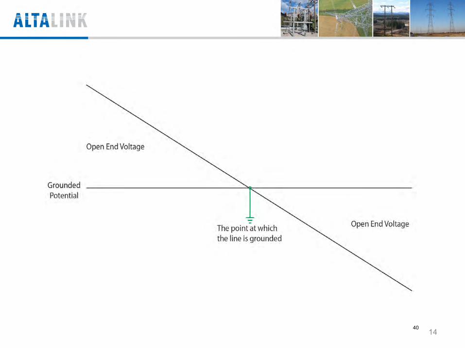
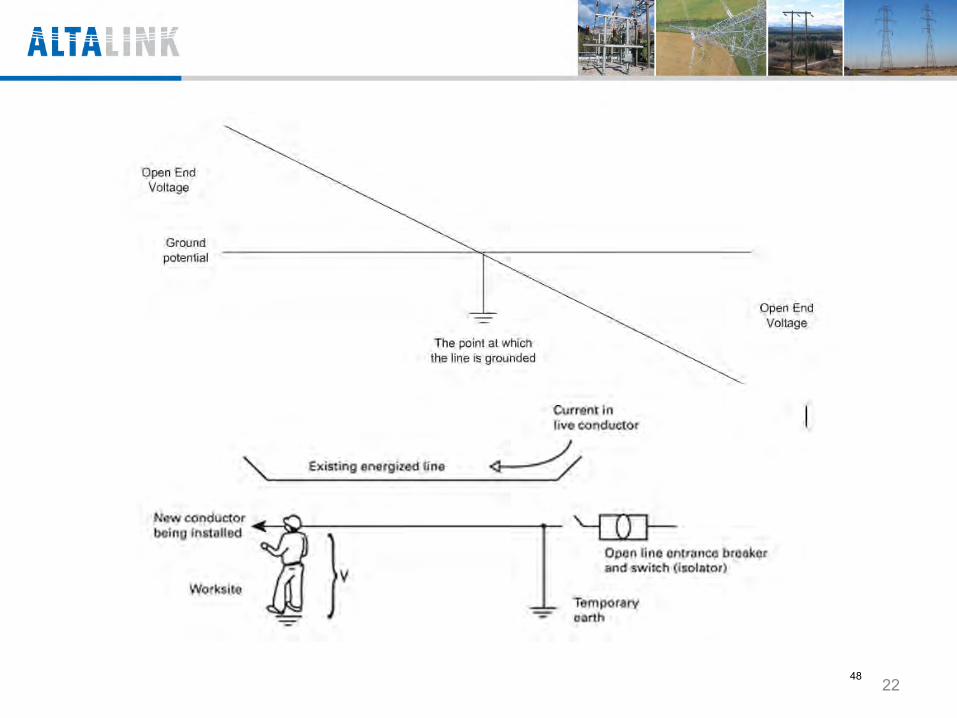
Magnetic Induction (cont’d) • The magnetic induced voltage on a power line will
increase as you move away from the portable protective grounds
• This is called open-end voltage
21 47
22 48
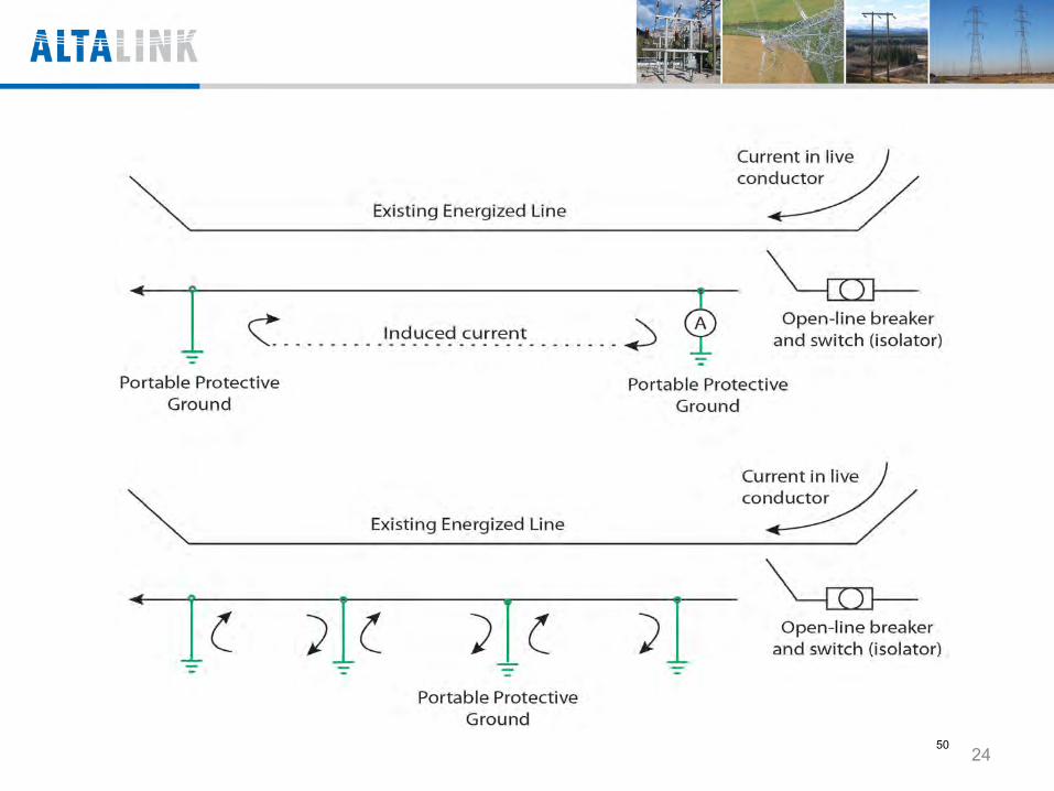
Magnetic Induction Summary • When you install a 2nd set of personal protective
grounds there will be a current flow between the 2 sets of grounds
• The amount of current that will flow in this circuit will depend on the current flowing on the energized line, the separation between the lines, the distance between the grounds and the total impedance of the circuit
• This includes the impedance of the line and the resistance of the grounds
• This circulating current is normally much higher than the steady state current flow from capacitive induction
23 49
24 50
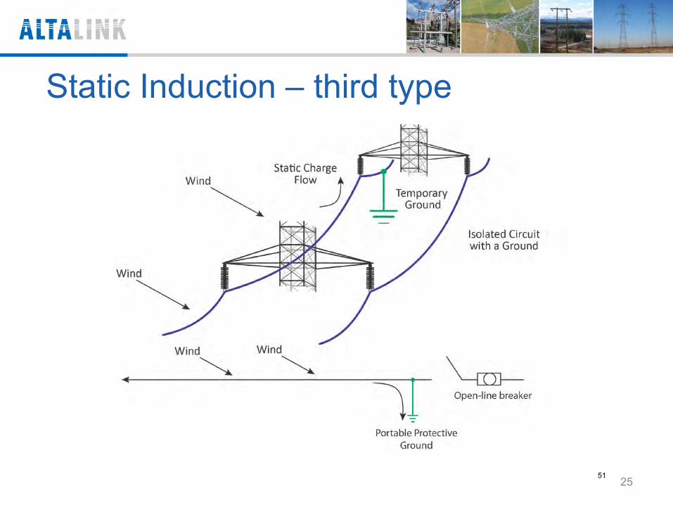
Static Induction – third type
25 51
Hazards of Step & Touch Potentials • When there is a voltage difference between your hands
and your feet, it is called touch potential
• When there is a voltage difference between your feet, it is called step potential
26 52
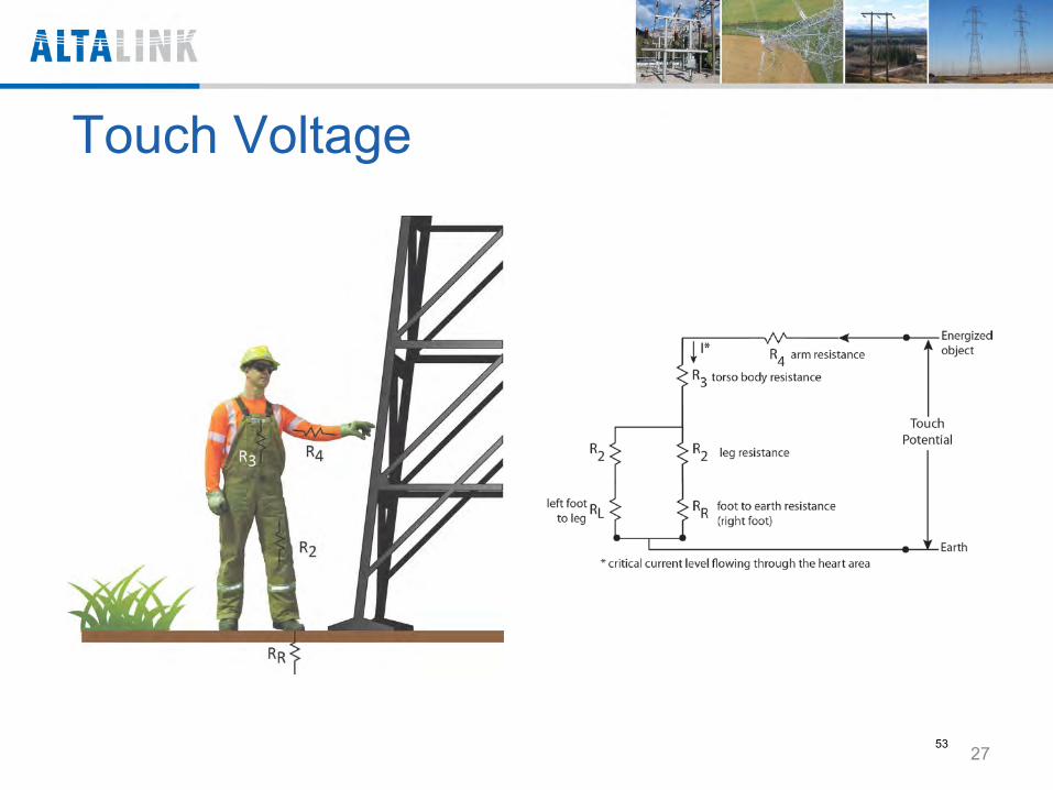
Touch Voltage
27 53
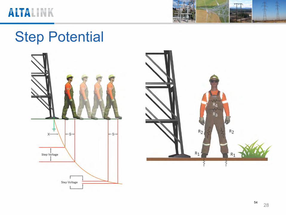
Step Potential
28 54
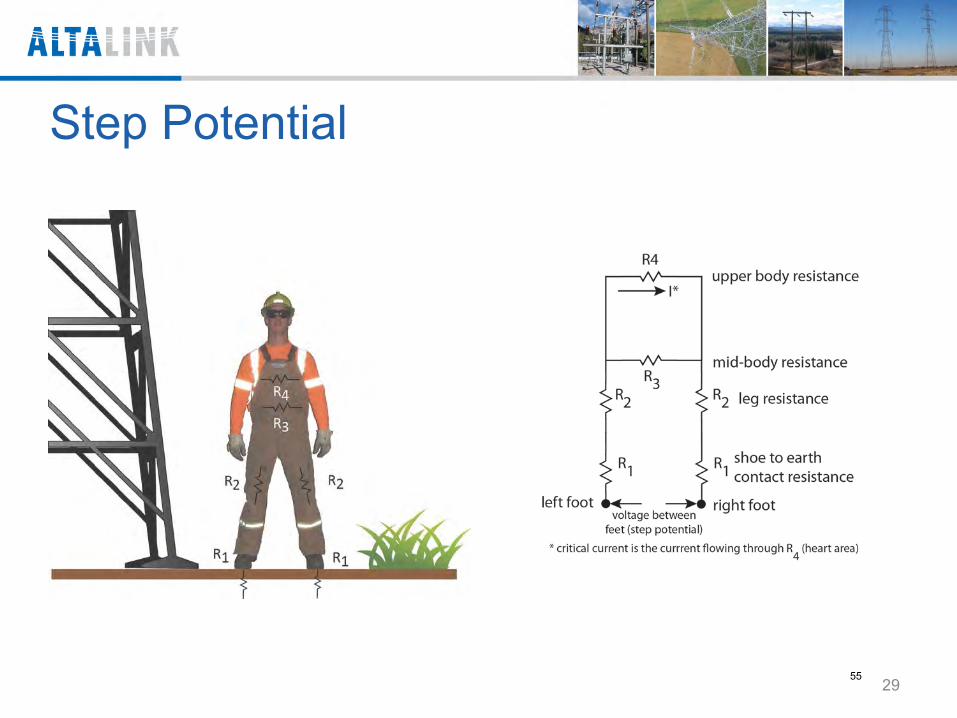
29
Step Potential
55
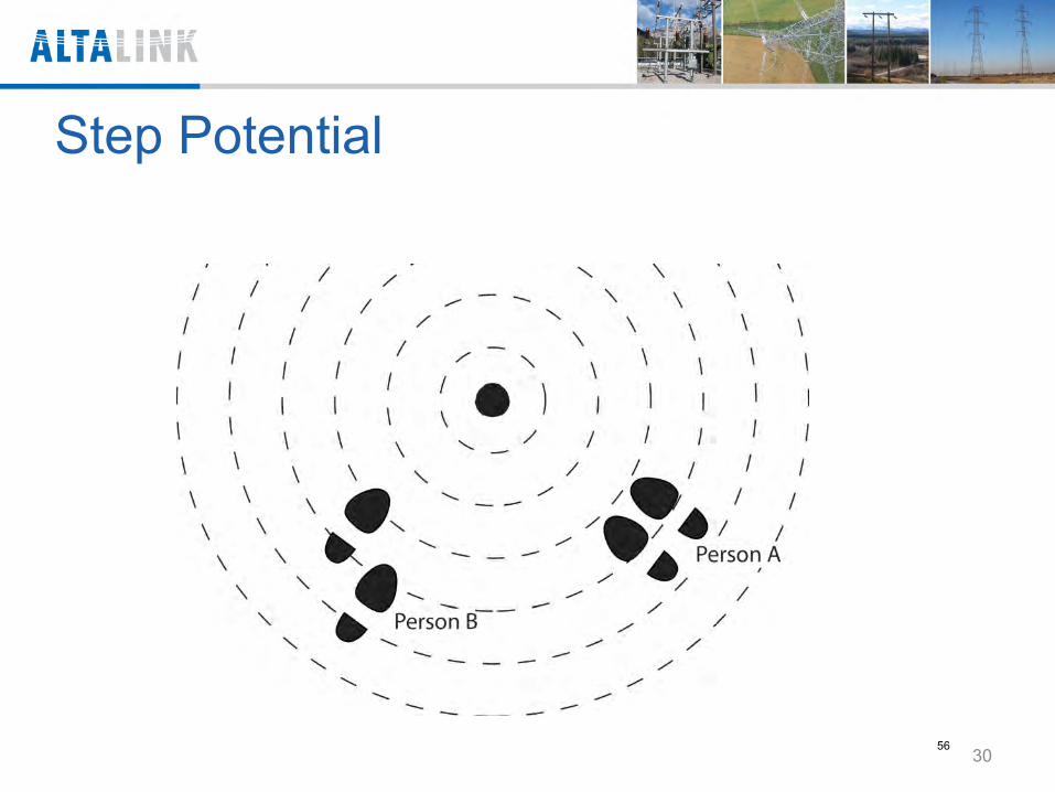
30
Step Potential
56
3. Grounding and Bonding • Bracket grounding • Equipotential Grounding and Bonding
31 57
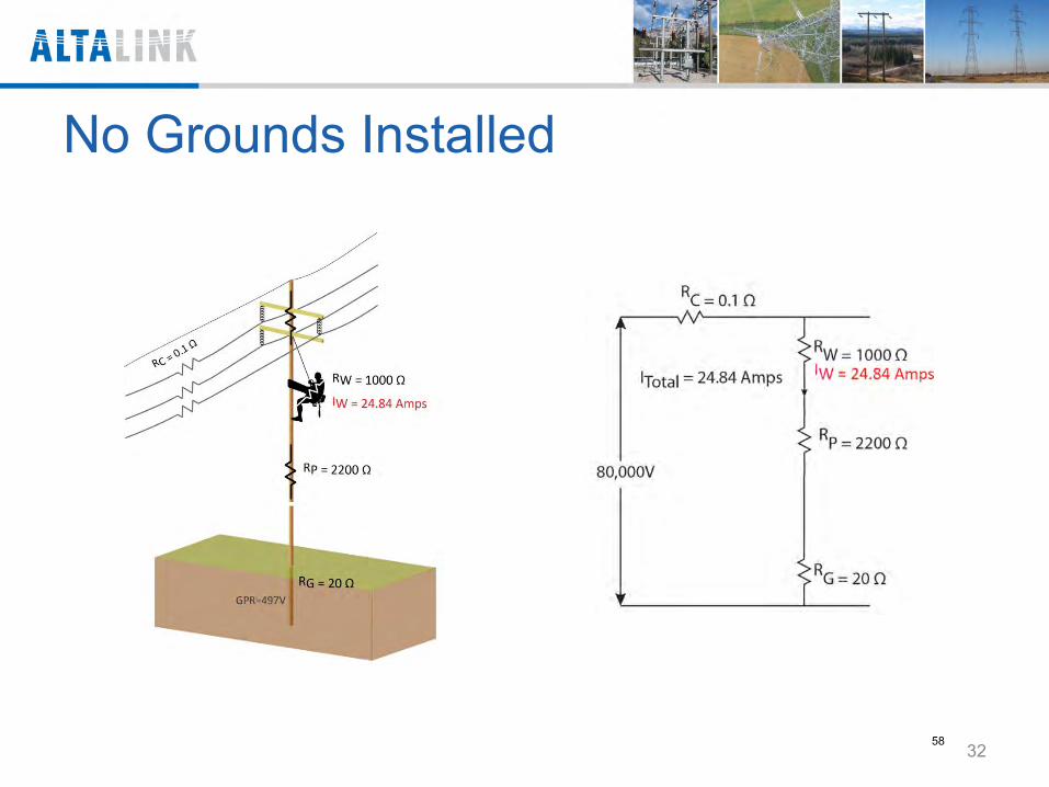
No Grounds Installed
32 58
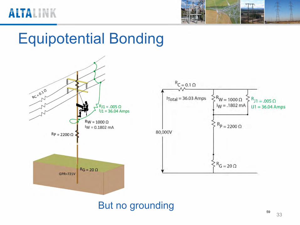
Equipotential Bonding
33 But no grounding
59
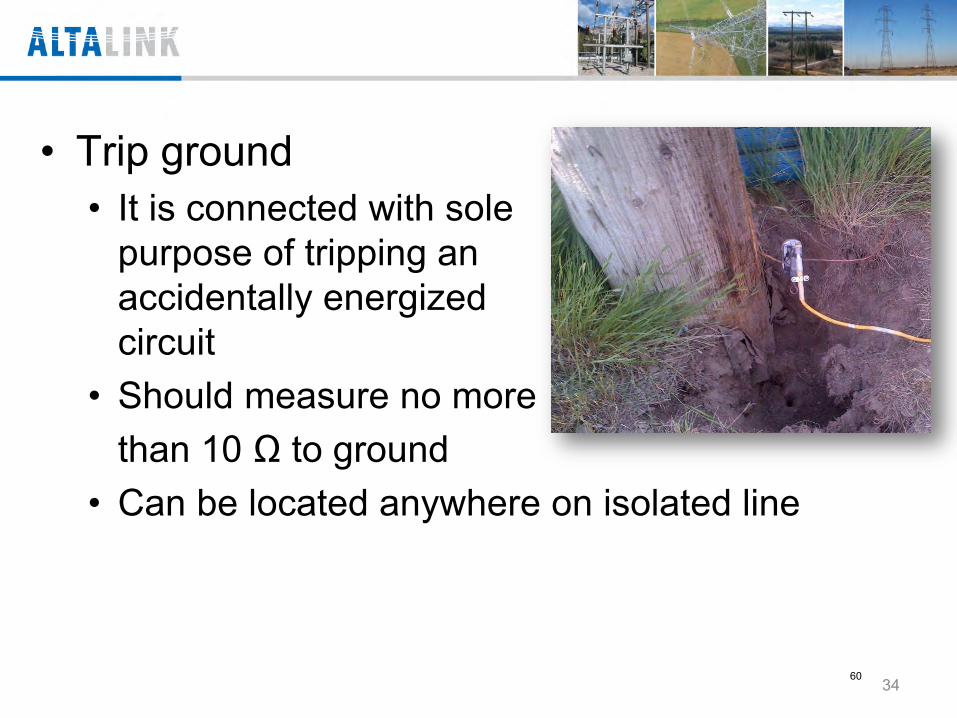
• Trip ground • It is connected with sole
purpose of tripping an accidentally energized circuit
• Should measure no more than 10 Ω to ground • Can be located anywhere on isolated line
34 60
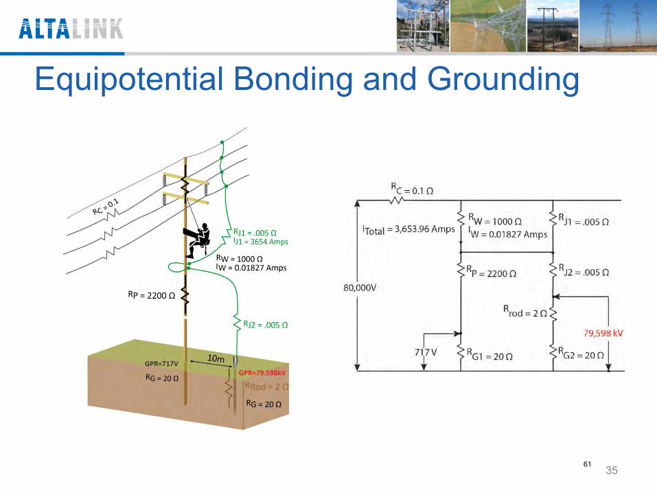
Equipotential Bonding and Grounding
35 61
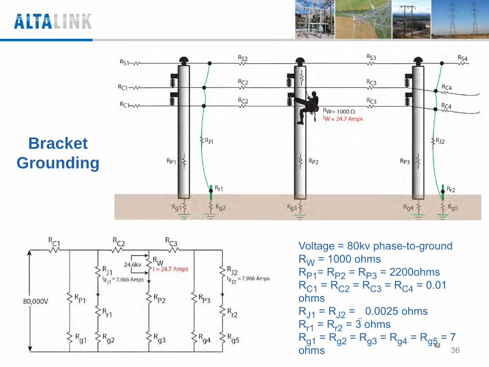
Voltage = 80kv phase-to-ground RW = 1000 ohms RP1= RP2 = RP3 = 2200ohms RC1 = RC2 = RC3 = RC4 = 0.01 ohms RJ1 = RJ2 = _ 0.0025 ohms Rr1 = Rr2 = 3 ohms Rg1 = Rg2 = Rg3 = Rg4 = Rg5 = 7 ohms
Bracket Grounding
36 62
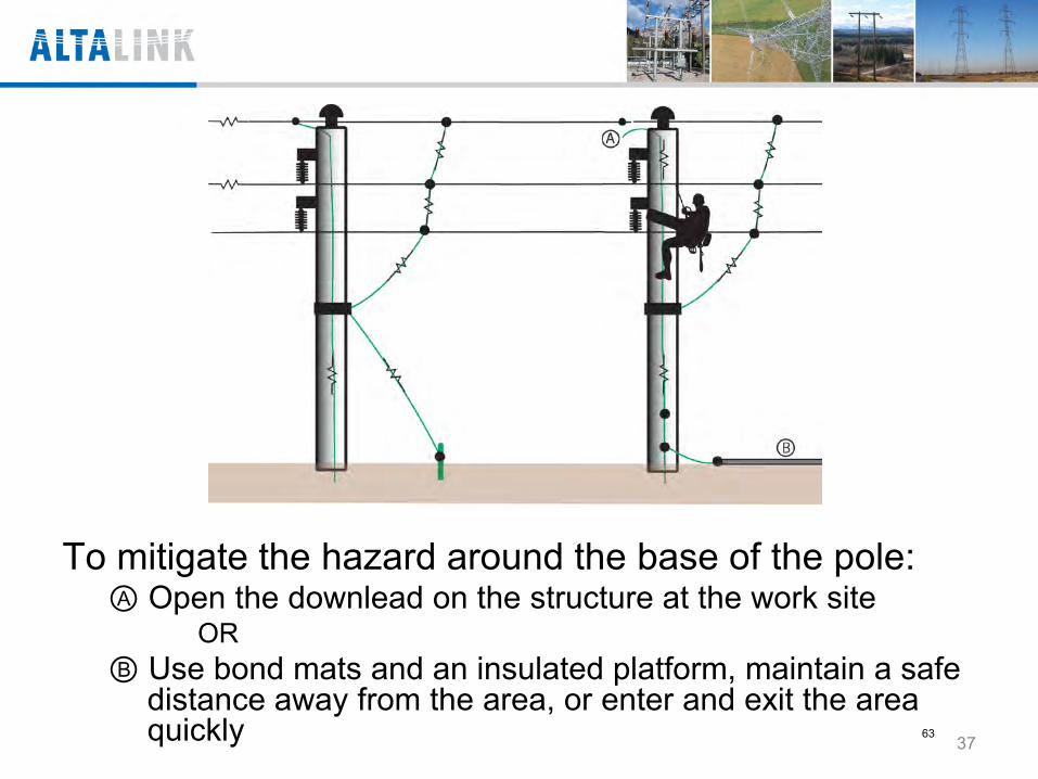
To mitigate the hazard around the base of the pole: Open the downlead on the structure at the work site
OR Use bond mats and an insulated platform, maintain a safe
distance away from the area, or enter and exit the area quickly
37
63

To mitigate the hazard around the base of the pole: Open the downlead on the structure at the work site
OR Use bond mats and an insulated platform, maintain a safe
distance away from the area, or enter and exit the area quickly
38
64
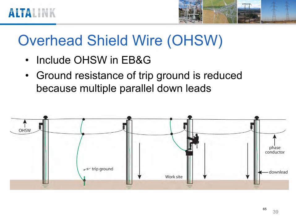
Overhead Shield Wire (OHSW) • Include OHSW in EB&G • Ground resistance of trip ground is reduced
because multiple parallel down leads
39 65
In a complex grounding situation where human error may increase the likelihood of a hazard being created through an error in applying or removing grounds in wrong sequence:
Addition of: • Two bleed grounds will lower hazard of induction and • Grounds should not be more than 1 to 1 1/2 spans
from worksite
40 66
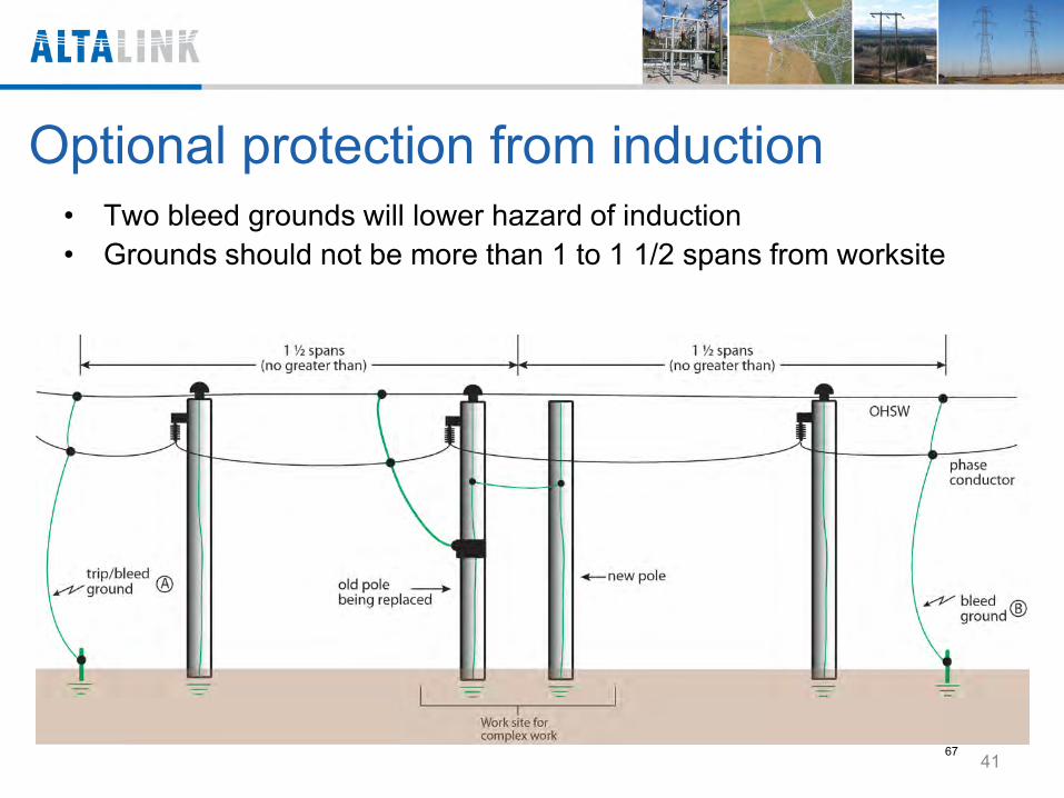
Optional protection from induction • Two bleed grounds will lower hazard of induction • Grounds should not be more than 1 to 1 1/2 spans from worksite
41 67
Questions
42 68
Question 1 • What are the two primary hazards safety
grounding is addressing? Line energization Induction
69
Question 2 • The effect of current passing through the
body depend on what factors? • Duration of the current flow, • Magnitude of the current flow, and • Frequency of this current
70
Question 3 • What the primary purpose of a trip
ground? To provide a low ohms circuit to ground to
cause the protection to clear the fault as fast as possible.
71
Question 4 • What is the primary purpose of bonds?
To protect a worker by creating a
equipotential zone and limiting the voltage across a workers body.
72
Question 5 • What is bracket grounding and what is it
main limitation? It placing grounds on all sources of energy
and the worker works between the grounds. Bracket grounding does not protect the
worker from line energization. Bracket grounding does trip the circuit and
clears the fault.
73
Working on Isolated Transmission Facilities May, 2013
74
AGENDA 1. AltaLink Work Methods:
• EBG - Lines and Substations • No Bond Zone • Live Line Methods • Modified No Bond Zone Method
2. Grounding Process • Eliminating human error during
grounding
2
75
Why do we bond and ground? 1) To protect linemen and substation workers from
harmful voltages and currents that exit on power system
2) Isolating power lines or equipment to work on them is not sufficient to protect workers from harmful voltages and currents
3) Bonds are applied to reduce voltages and currents to a safe level
4) Grounds are applied to result in faster fault clearing
3 76
Working Safely on Isolated Transmission Lines
There are 4 ways that we can safely work on lines: 1. Equipotential Bonding and Grounding 2. No Bond Zone 3. Modified No Bond Zone 4. Live Line Method
4 77
1. Equipotential Bonding and Grounding Applying Bonding • Equipotential bonding methods must be used
when the equipment being worked on can become energized
• Only the application of bonds in a EB&G zone can protect a worker from harmful currents
5 78
Applying Bonds (cont’d): • All conductive paths must be bonded together to
form an equipotential zone. To ensure you maintain equipotential zones the phases, neutrals, shield wires, guy wires and steel winch lines etc. must be bonded together.
6 79
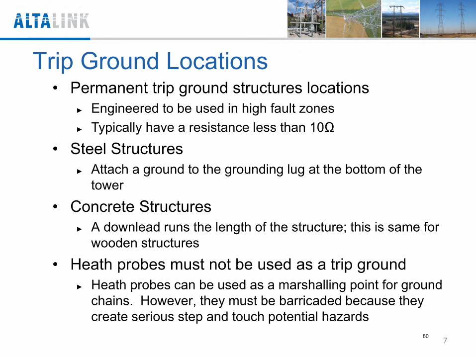
Trip Ground Locations • Permanent trip ground structures locations
Engineered to be used in high fault zones Typically have a resistance less than 10Ω
• Steel Structures Attach a ground to the grounding lug at the bottom of the
tower
• Concrete Structures A downlead runs the length of the structure; this is same for
wooden structures
• Heath probes must not be used as a trip ground Heath probes can be used as a marshalling point for ground
chains. However, they must be barricaded because they create serious step and touch potential hazards
7 80
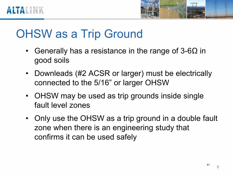
OHSW as a Trip Ground • Generally has a resistance in the range of 3-6Ω in
good soils
• Downleads (#2 ACSR or larger) must be electrically connected to the 5/16” or larger OHSW
• OHSW may be used as trip grounds inside single fault level zones
• Only use the OHSW as a trip ground in a double fault zone when there is an engineering study that confirms it can be used safely
8
81
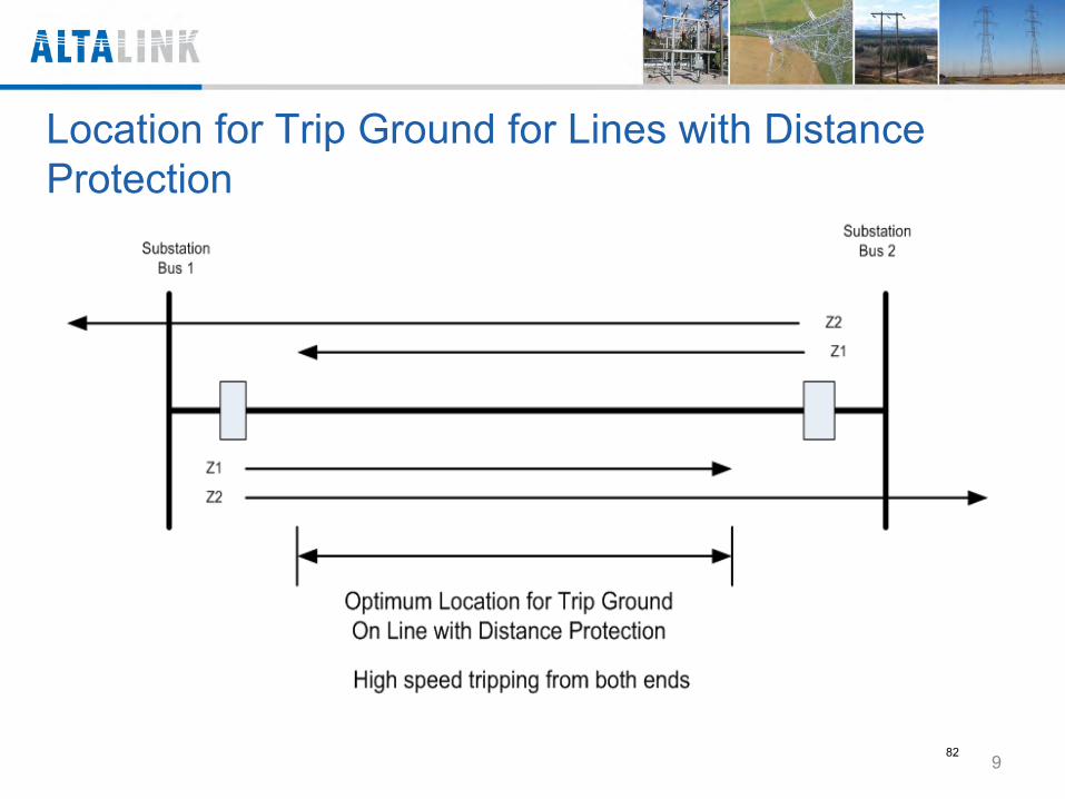
Location for Trip Ground for Lines with Distance Protection
9 82
Bonding Guy Wire and Anchors • Guy wires are not to be used in tripping circuits
Preforms could fail under fault conditions
• Guy wires are to be bonded into zone if required
• Anchors may be use in a tripping circuit if they have been meggered to less than 10 ohms
10 83
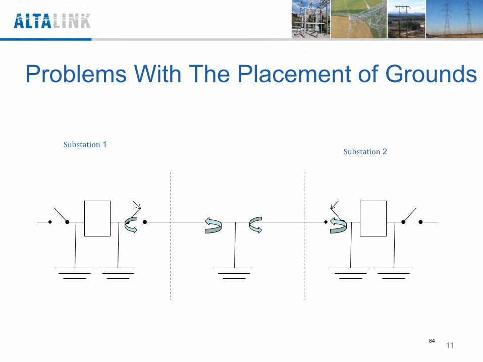
Problems With The Placement of Grounds
Substation 1 Substation 2
11 84
12 85
Housekeeping Hazards • Do not coil grounds
Creates a high impedance
• Use correct grounds
Must be equal lengths and as short as possible
• Secure and place grounds properly
Place out of the way for work to occur
May be tied down but not coiled
13 86
Installing Parallel Grounds • Ensure both sets are of exact length
Share fault current equally
• Install both grounds on one phase before moving to next phase
When only one ground is on, it is at risk of failure under fault condition
14 87
Mobile equipment without a boom • If a vehicle must be parked in the ground potential rise
zone and is not likely to contact the primary:
Vehicle should not be bonded into the zone
Workers are still at risk of touch potential but to a lesser degree
• Use of a bond mat attached to the vehicle mitigates the touch potential problem
15 88
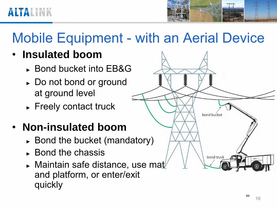
Mobile Equipment - with an Aerial Device
• Non-insulated boom Bond the bucket (mandatory) Bond the chassis Maintain safe distance, use mat
and platform, or enter/exit quickly
• Insulated boom Bond bucket into EB&G Do not bond or ground
at ground level Freely contact truck
16 89
Protecting People on the Ground General Practices
• Apply trip grounds or ground rods away from work site
• Install grounds or bonds with an insulated stick • Flag/barrier equipment and work sites in urban
areas
17 90
Protecting Workers around Mobile Vehicles • Remove items you need from the vehicle • Use bond mats or insulated platforms • Stay 5 meters (16’ 5”) away from vehicles or
equipment that is tied into EB&G zone • To access a bucket truck, either move boom
out harms way and remove truck chassis ground, or enter/exit quickly
18 91
Protecting Workers around Mobile Vehicles • To access a truck hoisting a load, either
remove grounds and move load, or enter/exit quickly
• Disconnect the truck when the truck is no longer needed in EB&G zone
• Remove ground-rod end first and then remove ground from truck chassis
19 92
Bond Mats • Bond mats are to be used to bond a person to an
EB&G zone
• Must not be used as a grounding mat
Bond mats are not designed for fault current Only use a bond mat when there is a trip grounding
on the circuit
20 93
Using Bond Mats • Mitigate step and touch potential
• Stand on mat and then connect the mat to equipment with an insulated stick
21 94
Using Bond Mats To step off bond mats, do one of the following:
• Use an insulated platform between mat and area outside GPR Zone
Or • Move quickly in and out of the area
22 95
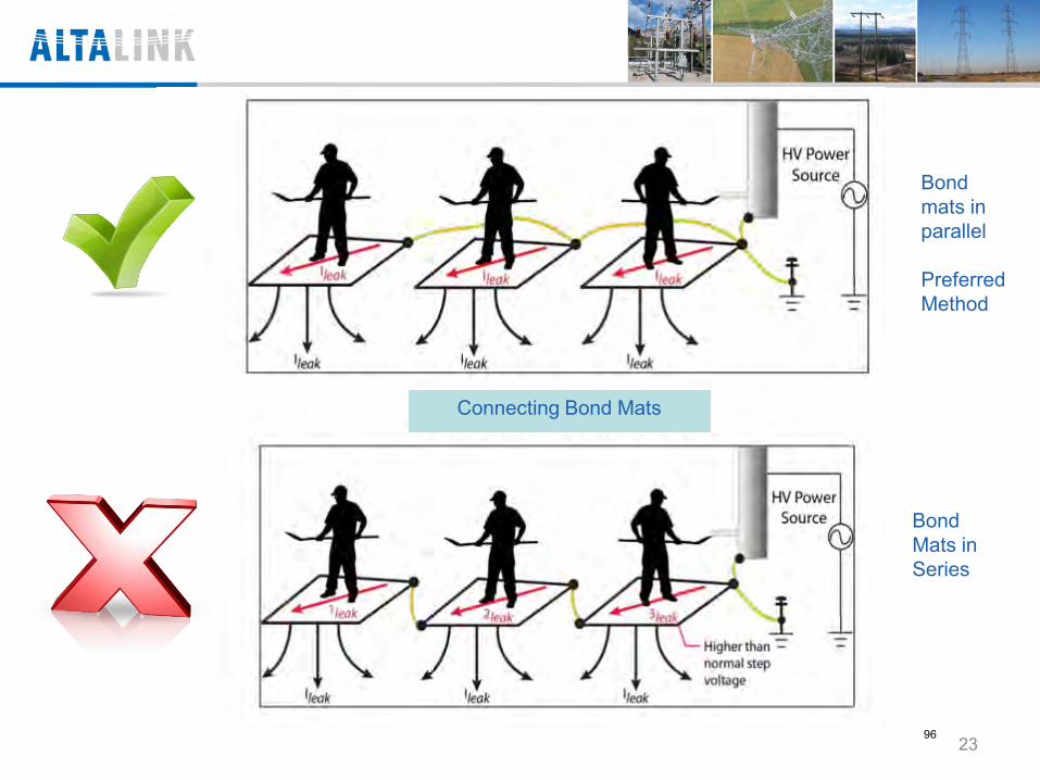
Bond mats in parallel Preferred Method
Bond Mats in Series
Connecting Bond Mats
23 96
Grounding in a substation • Substations are different from lines in two
ways: Substation ground grid along with all
permanent conductive objects in the substation are grounds to the grid. This creates basically an EBG zone
Insulating gravel and ground grid protects workers on the ground
24 97
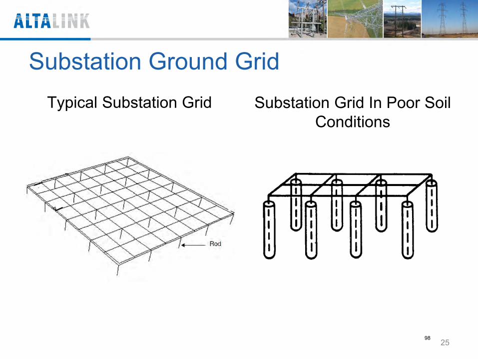
Substation Ground Grid Typical Substation Grid Substation Grid In Poor Soil
Conditions
25 98
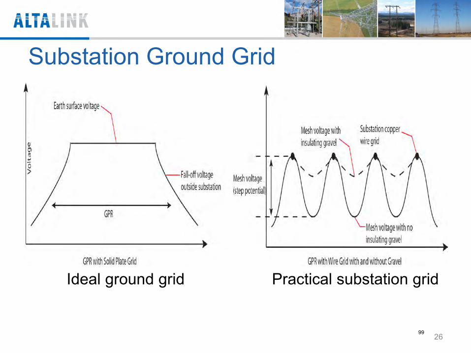
Substation Ground Grid
Ideal ground grid Practical substation grid
26 99
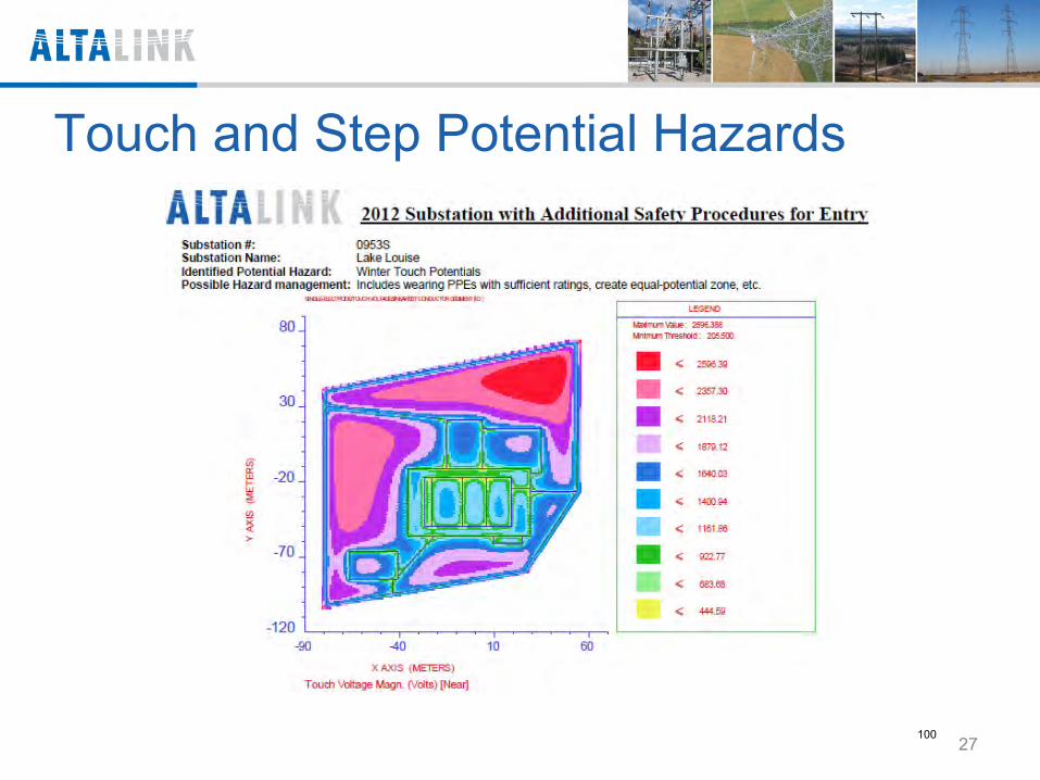
Touch and Step Potential Hazards
27 100
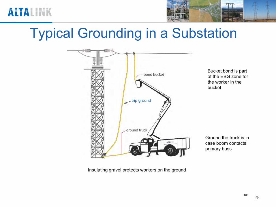
Typical Grounding in a Substation
trip ground
Ground the truck is in case boom contacts primary buss
Insulating gravel protects workers on the ground
Bucket bond is part of the EBG zone for the worker in the bucket
28 101
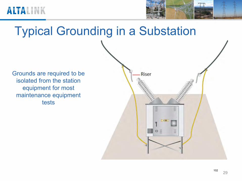
Typical Grounding in a Substation
Grounds are required to be isolated from the station
equipment for most maintenance equipment
tests
29 102
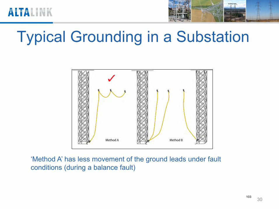
Typical Grounding in a Substation
‘Method A’ has less movement of the ground leads under fault conditions (during a balance fault)
30 103
2. No Bond Zone Method • When it not practical to use EBG method • Often used after a storm when significant
amount of conductor is on the ground • A No Bond Zone is defined as a zone where
there is an additional separation point in addition to the Guarantee of Isolation (GOI) point and there is NO possible way that section of line can become energized
31 104
No bond zone requirements: • Second set of barriers in addition to ACC GOI isolation
points • Conductor must be physically isolated • Bleed ground
Bleeds off static induction Install within sight of the work whenever practical
• No induction In induction corridors, all parallel circuits must be de-
energized Line crossings must be near perpendicular to ensure
magnitude of induction is not harmful Second barrier must be created at the crossing to
protect against accidental energization 32
105
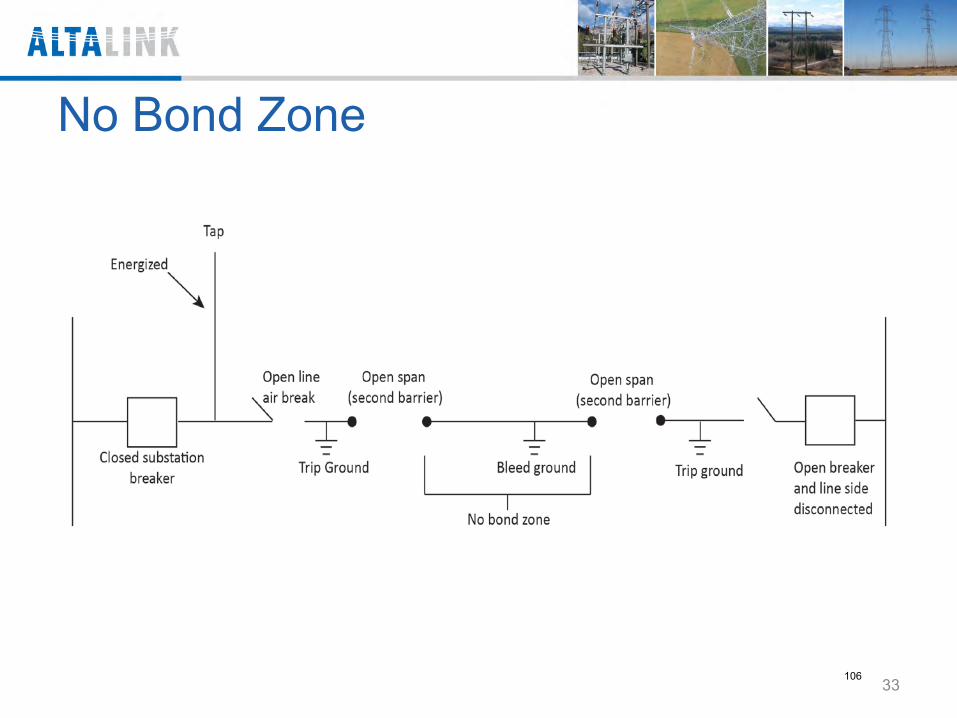
No Bond Zone
33 106
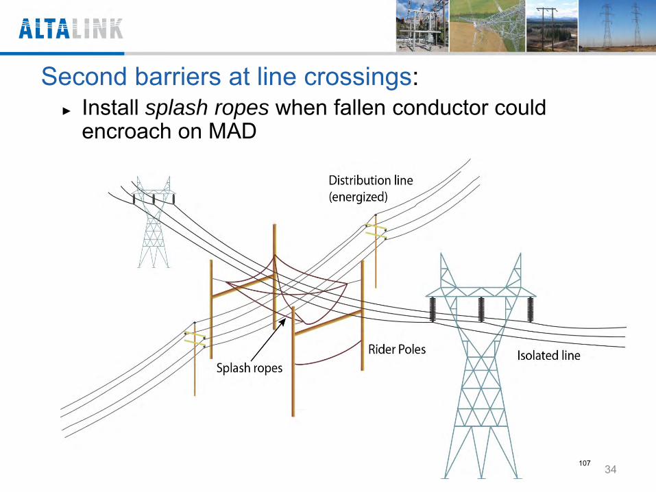
Second barriers at line crossings: Install splash ropes when fallen conductor could
encroach on MAD
34 107
3. Live Line Method
• The line is isolated and grounded (trip ground) • Workers treat it as a live line and use live line
tools and techniques • Assume line voltage to be line nominal voltage
rating
35 108
4. Modified No Bond Zone • Is a method that combines elements of no bond zone
and live line method
• Often used when ‘no bond zone’ cannot be used due to the presence of induction
The line is isolated with second open points (open spans) [This eliminates re-energization of the line]
Induction is managed live line techniques at a reduce voltage level (permits the use of Class 4 rubber gloves)
36 109
Grounding Practices Process 1. Is grounding complex or non-complex?
Complex grounding occurs at more than one work site or involves more than one work crew
2. Create a project grounding plan Outlines hazards and mitigations for all sites Required for complex grounding only Signed by project grounding leader
3. Review the project grounding plan Signed by competent second set of eyes
37
110
Grounding Practices Process cont’d 4. Communicate the project grounding plan
At start-up meeting Participants sign attendance sheet
5. Create a site grounding plan Outlines electrical hazards and mitigations for
one site Required for complex and non-complex
grounding Use Safe Work form in Safety and Health
Library Signed by site grounding leader
38 111
Grounding Practices Process cont’d
6. Review the site grounding plan Signed by competent second set of eyes
7. Communicate the site grounding plan At tail-board meeting On-site workers sign Safe Work Plan
39 112
Grounding Practices Process cont’d
8. Execute grounding according to the site grounding plan
Minimum two workers Third person as safety observer (optional) Before each step, read out and repeat If changes required, stop work, revise,
communicate 9. Submit all grounding plans for review
External contractor crews return to AltaLink project manager
AltaLink crews return to your manager
40 113

Questions
41 114
Question 1 • What are the four methods used by
AltaLink to work on isolated transmission lines?
EBG No Bond Zone Live Line Methods Modified No Bond Zone
115
Question 2 • If the center section of a line is the ideal
location for a trip ground, when would you place the trip ground in a substation?
If you can not find a good low ohms ground location. i.e. in mountains
116
Question 3 • Why would you ground a truck chassis?
To protect the truck. It does not protect the
workers on the ground.
117
Question 4 • How do you protect workers on the
ground?
Keep them away from the GPR zone (ribbon off area)
Bond mats or insulated platform Remove fault current injection point (if
possible)
118
Question 5 • What are two primary difference affecting
grounding in a substation versus transmission line?
Substation ground grid – all non energized conductive objects are connected to ground grid. Basically a EGB zone
Insulating gravel.
119
1
Deep-ground-well method used for improving
the grounding resistance of HV substation grounding system
Alberta Power Industry Consortium (APIC) Grounding Seminar
Calgary, May 28th, 2013; Edmonton, May 30th, 2013, Presenter: Nerkez Lalic, P.Eng.
Senior Manager Transmission Projects, EPCOR DTI
120
2
1. Introduction Achieving low resistive earth grounding of a substation grounding system (electrode) is primarily in function of:
• Resistivity of earth the grounding electrode is placed in • Relative size of the grounding system itself.
In most cases, we as engineers have no control over the available size of the substation, and we certainly have no control of the soil / earth conditions at the site. As such, we need to evaluate the most effective method of achieving low resistive earth grounding of a substation grounding system in order to control Earth Potential Rise / Ground Potential Rise outside substation area.
121
3
Earth Potential Rise (EPR) also called Ground Potential Rise (GPR) occurs when a large current flows to earth through grounding system resistance / impendence. Ground Potential Rise or Earth Potential Rise (as
defined by IEEE Standard 80-2000) is the maximum electrical potential that a (substation) grounding grid may reach with reference to a distant grounding point - potential of remote earth.
This voltage - GPR, is equal to the maximum grid current times the grid resistance.
2. Earth Potential Rise (EPR) / Ground Potential Rise (GPR)
122
4
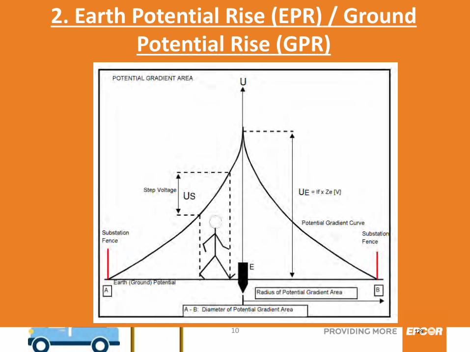
2. Earth Potential Rise (EPR) / Ground Potential Rise (GPR)
The change in voltage over distance (potential
gradient) may be so high that a person could be injured due to the voltage developed between two feet, or between the ground on which the person is standing and a grounded metal object. Probably the most commonly noted Ground
Potential Rise or Earth Potential Rise event involves the death of cows in a field during a lightning strike.
123
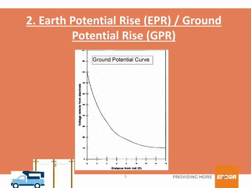
5
2. Earth Potential Rise (EPR) / Ground Potential Rise (GPR)
124
6
• Transferred potential through any conducting object connected to the substation earth ground is a hazard to people and equipment outside the substation.
• Earth potential rise (EPR) is caused by electrical faults
that occur at electrical substations, generating stations, or high-voltage transmission lines.
2. Earth Potential Rise (EPR) / Ground Potential Rise (GPR)
125
7
• The potential rise can cause hazardous voltage, many hundreds meters away from the actual fault location.
2. Earth Potential Rise (EPR) / Ground Potential Rise (GPR)
126
8
Number of factors determine the level of potential rise, including: Magnitude of fault current, Earth type, Earth moisture, Ambient and earth temperature, Underlying rock layers Clearing time to interrupt a fault.
2. Earth Potential Rise (EPR) / Ground Potential Rise (GPR)
127
9
Earth potential rise is a SAFETY ISSUE. An EPR event at a site such as an electrical transmission and distribution substation may expose personnel, users, public and properties to dangerous voltages.
2. Earth Potential Rise (EPR) / Ground Potential Rise (GPR)
128
10
2. Earth Potential Rise (EPR) / Ground Potential Rise (GPR)
129
11
Comment on figure “Potential Gradient Area”:
• If the potential gradient area, having diameter A-B, is within substation fence dangerous potentials can be controlled by creating equipotential zones, insulating equipment (PPE), and restricted work areas as described below.
• If potential gradient area, having diameter A-B, is outside substation fence dangerous potentials are in the public zone and that can be mitigated by improving grounding resistance (impedance). i.e. reducing EPR (Ue) and reducing diameter of potential gradient area to within substation fence.
2. Earth Potential Rise (EPR) / Ground Potential Rise (GPR)
130
12
• "Step potential" is already discussed and there is no need to repeat. • "Touch potential" is already discussed and there is no need to repeat. • "Ground Potential Difference (GPD)" is a factor calculated when a grid of grounding conductors is installed. GPD potential is the difference between the metallic object connected to the grid, and the potential of the soil within the grid. This can be a problem if equipotential zone is poorly designed and installed.
3. Step, Touch Potential and Ground Potential Difference (GPD)
131
13
The grounding grid is one of the most challenging aspects in design of new and safe operation of in-service substations. An engineering analysis of the power system under fault conditions can be used to determine whether or not hazardous step and touch voltages will develop. The result of this analysis can show the need for protective measures and can guide the selection of appropriate precautions.
4. MITIGATION
132
14
Several methods may be used to protect employees from hazardous ground-potential gradients: •The creation of an equipotential zone will protect a worker standing within it from hazardous step and touch potentials. Equipotential zones will not, however, protect employees who are either wholly or partially outside the protected area. •Bonding conductive objects in the immediate work area can also be used to minimize the potential between the objects and between each object and ground.
4. MITIGATION
133
15
•The use of insulating Personal Protective Equipment (PPE), such as rubber gloves, can protect employees handling grounded equipment and conductors from hazardous touch potentials. •Restricting employees from areas where hazardous step or touch potentials could arise can protect employees not directly involved in the operation being performed.
4. MITIGATION
134
16
•It is common practice to cover the surface with a high-resistivity layer of crushed stone or asphalt. The surface layer provides a high resistance between feet and ground grid and is an effective method to reduce the step and touch potential hazard. •Improve grounding resistance/impedance – by increasing ground grid (substation) size and / or application of low resistive earth grounding, considering that magnitude of fault current is determined with fixed number of amperes. The only variable that can be changed is earth resistance (impedance) of grounding system.
4. MITIGATION
135
17
A well designed grounding grid can eliminate Step and Touch potential hazards regardless of how high the Ground Potential Rise voltage is. Just like how a bird can land on a power line without being electrocuted properly designed equipotential zones inside substation can do the same thing.
4. MITIGATION
136
18
Background: In the middle of eighties a number of studies were done to determine the most effective method of installing low resistive earth grounding. Various grounding methods and materials were evaluated. The majority of the standard methods were rejected for practicality or cost reasons. New methods of using chemical rods and soil conductivity improvement materials looked promising but left unanswered questions as to environmental impact and liabilities. There is concern about ground water contamination from the chemicals.
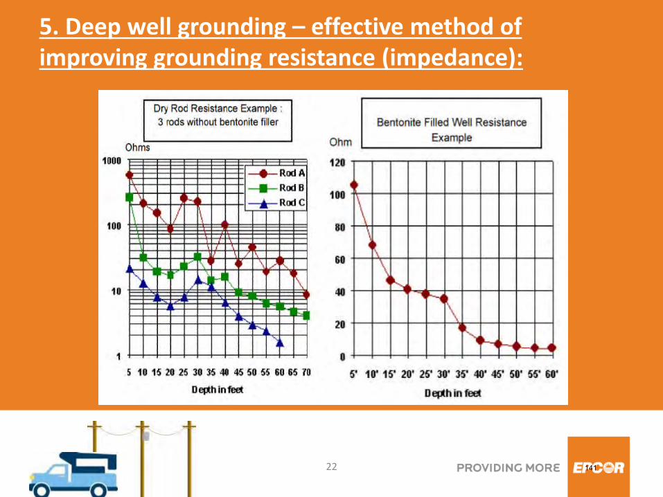
5. Deep well grounding – effective method of improving grounding resistance (impedance):
137
19
Based on the studies it was determined that deep driven ground rods would offer the best solution for low resistive earth grounding if full rod contact with surrounding earth could be achieved and maintained. In achieving full rod contact with surrounding earth use of hydrated sodium bentonite of specific electric conductance and sealing characteristics has given excellent results.
5. Deep well grounding – effective method of improving grounding resistance (impedance):
138
20
As substation space is limited, realistically the only remaining way to improve earth resistance and reduce GPR to the acceptable values is to drive deep electrodes. It is not uncommon to see 100-meter (300+ ft) deep electrodes at some sites. The advantages of deep driven electrodes are:
5. Deep well grounding – effective method of improving grounding resistance (impedance):
139
21
• economical to install, • maintain low resistance over time, • maintenance free, • no environmental concerns.
With new technologies a new processes are developed for installing deep driven ground rods. This processes overcomes the problems associated with installing deep ground rods.
5. Deep well grounding – effective method of improving grounding resistance (impedance):
140
22
5. Deep well grounding – effective method of improving grounding resistance (impedance):
141
23
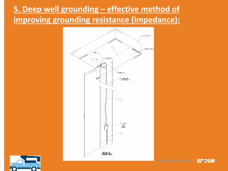
5. Deep well grounding – effective method of improving grounding resistance (impedance):
142
24
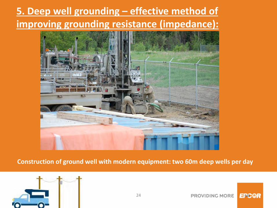
5. Deep well grounding – effective method of improving grounding resistance (impedance):
Construction of ground well with modern equipment: two 60m deep wells per day
143
25
A good ground system design demands computer modeling that can simulate the effects of an electrical fault on a 3D model of substation, taking into account such factors as conductor spacing and depth, X/R, soil resistivity, human
fibrillation currents, ground coverings, etc.
6. Ground System Design
144
26
EPCOR Poundmaker POD 240/25kV, 3x75MVA substation grounding grid design installation testing
and commissioning utilizing deep well grounding (nine wells 60 meters - 200 feet each) to improve
substation grounding system resistance
7. CASE STUDY
145
27
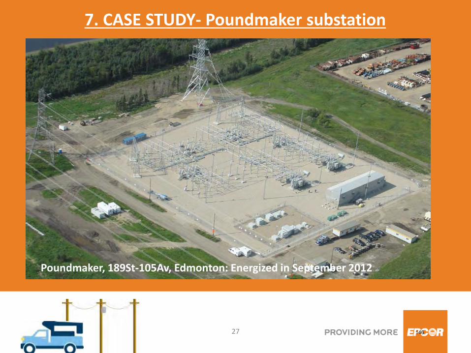
7. CASE STUDY- Poundmaker substation
Poundmaker, 189St-105Av, Edmonton: Energized in September 2012
146
28
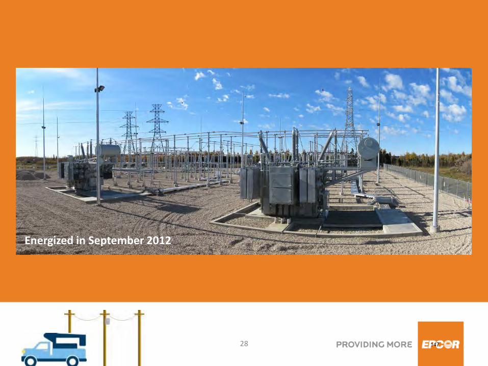
Energized in September 2012
147
29
Title
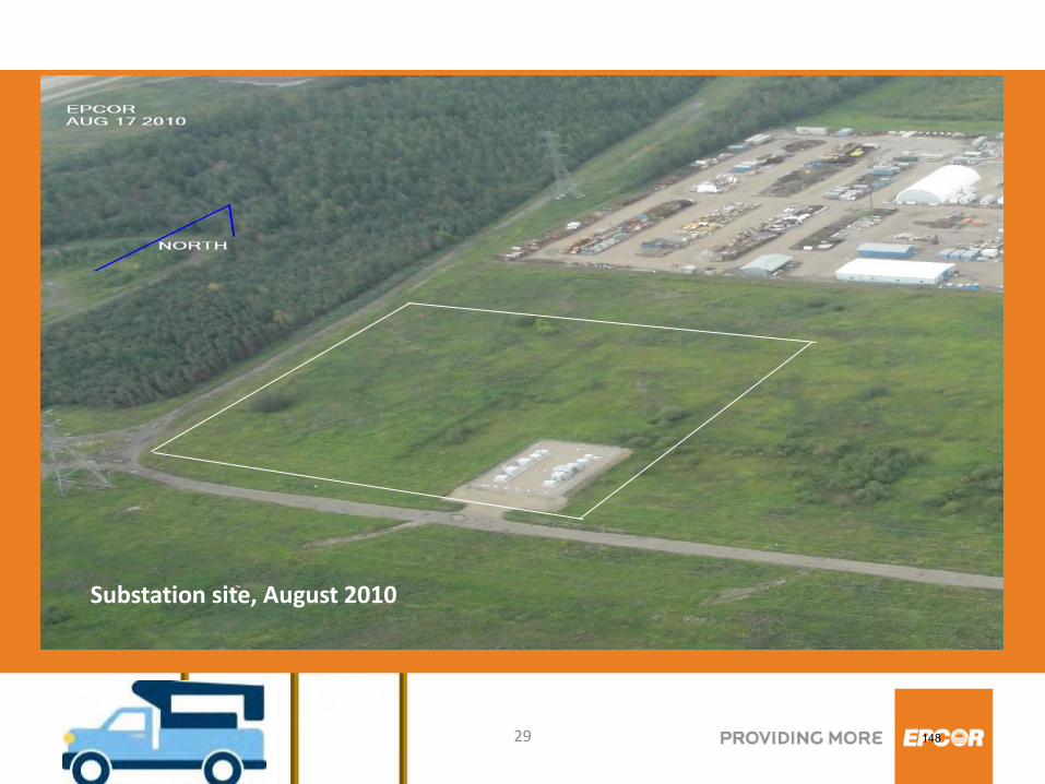
Substation site, August 2010
148
30
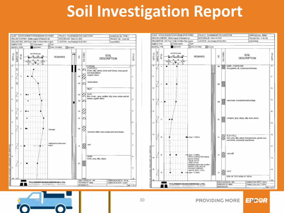
Soil Investigation Report
149
31
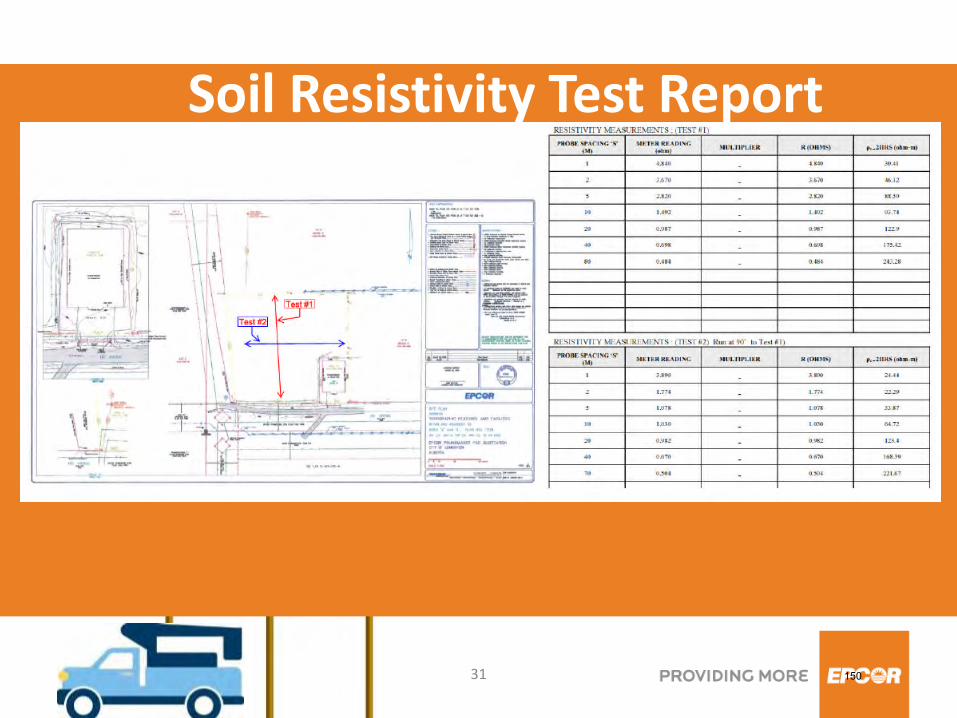
Soil Resistivity Test Report
150
32
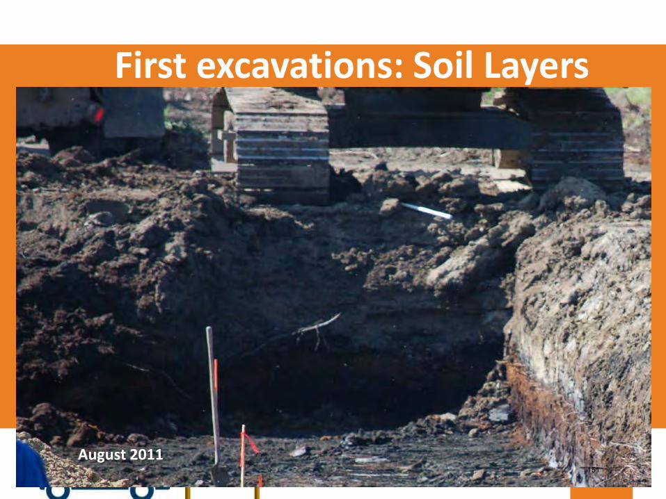
First excavations: Soil Layers
August 2011 151
33
The EPCOR Poundmaker substation grounding grid was designed by: CANA High Voltage Ltd
#31, 4511 Glenmore Trail SE Calgary, AB T2C 2R9
Phone: 403-451-6408 Fax: 403-247-4729
The soil resistivity test and fall of potential data were used to develop SES - CDEGS Software Package (Current Distribution, Electromagnetic Fields, Grounding and Soil Structure Analysis) model of the substation site. The substation grounding configuration, insulating gravel, seasonal soil models, touch and step voltages were reviewed to evaluate safety at the site.
Grounding Study & Detailed Design
152
34
It was clear that challenging soil electrical characteristics and limited fenced area of substation will require more extensive than usual grounding system.
Grounding Study & Detailed Design
153
35
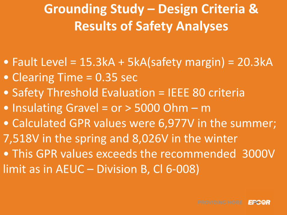
• Fault Level = 15.3kA + 5kA(safety margin) = 20.3kA • Clearing Time = 0.35 sec • Safety Threshold Evaluation = IEEE 80 criteria • Insulating Gravel = or > 5000 Ohm – m • Calculated GPR values were 6,977V in the summer; 7,518V in the spring and 8,026V in the winter • This GPR values exceeds the recommended 3000V limit as in AEUC – Division B, Cl 6-008)
Grounding Study – Design Criteria & Results of Safety Analyses
154
36
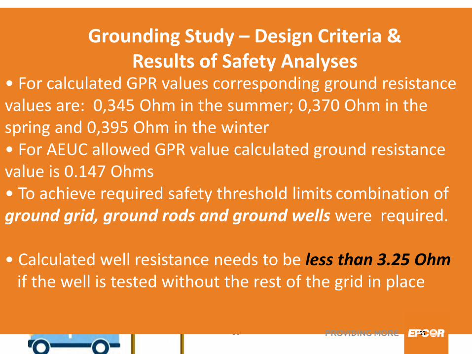
• For calculated GPR values corresponding ground resistance values are: 0,345 Ohm in the summer; 0,370 Ohm in the spring and 0,395 Ohm in the winter • For AEUC allowed GPR value calculated ground resistance value is 0.147 Ohms • To achieve required safety threshold limits combination of ground grid, ground rods and ground wells were required. • Calculated well resistance needs to be less than 3.25 Ohm if the well is tested without the rest of the grid in place
Grounding Study – Design Criteria &
Results of Safety Analyses
155
37
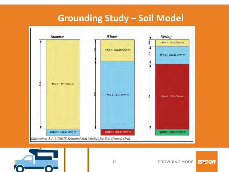
Grounding Study – Soil Model
156
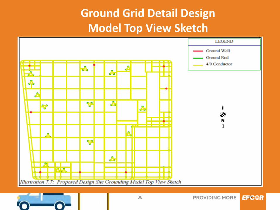
38
Ground Grid Detail Design Model Top View Sketch
157
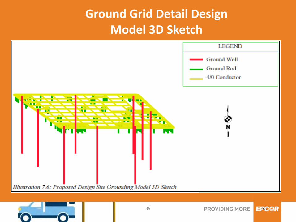
39
Ground Grid Detail Design Model 3D Sketch
158
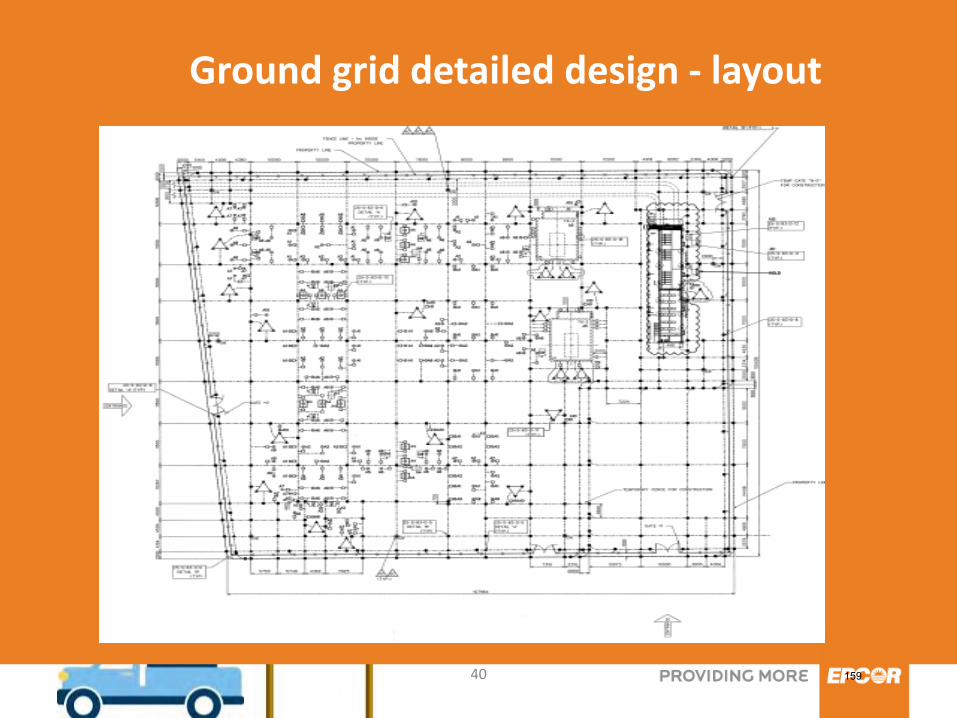
40
Ground grid detailed design - layout
159
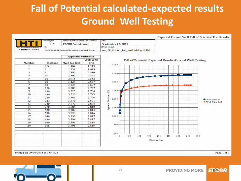
41
Fall of Potential calculated-expected results Ground Well Testing
160
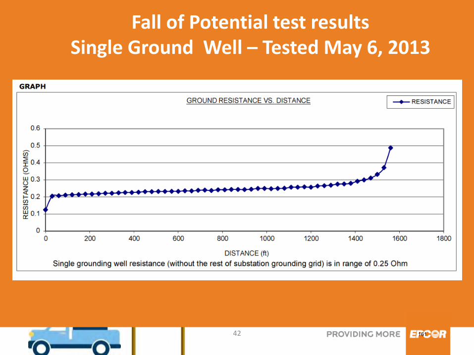
42
Fall of Potential test results Single Ground Well – Tested May 6, 2013
161
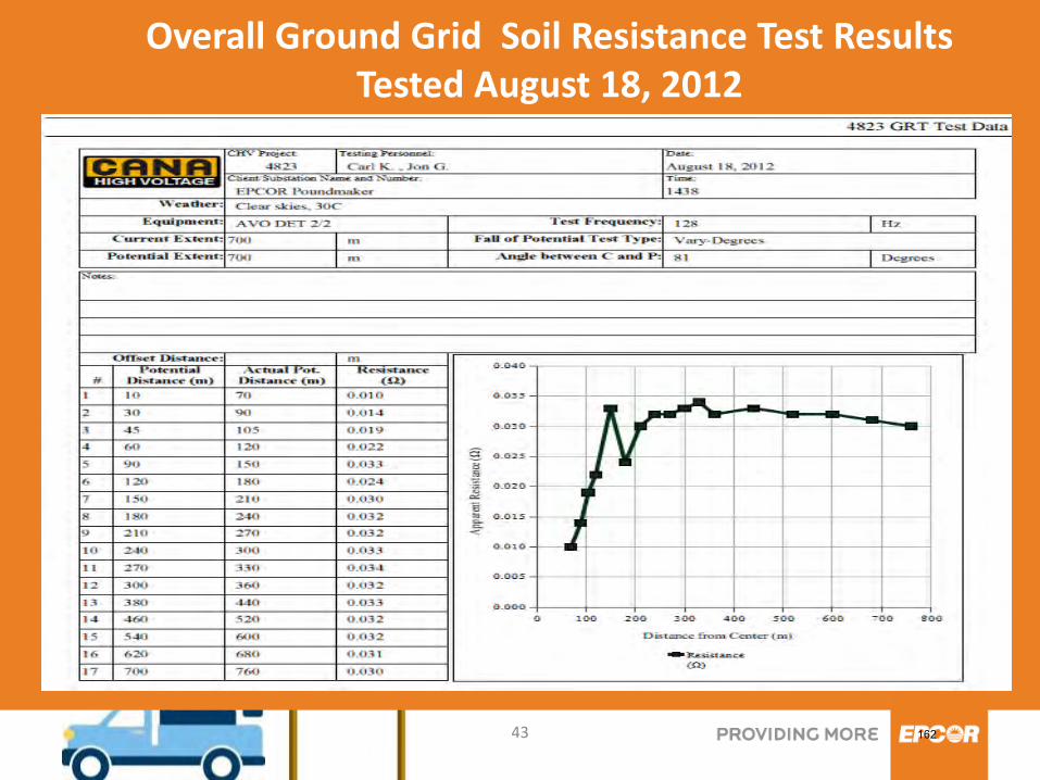
43
Overall Ground Grid Soil Resistance Test Results Tested August 18, 2012
162
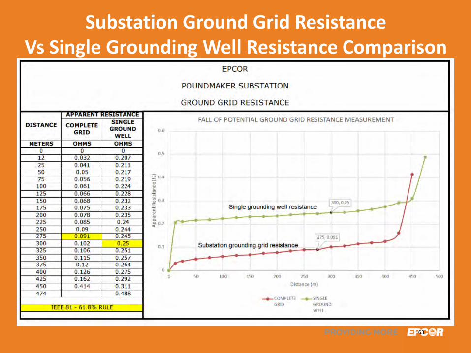
44
Substation Ground Grid Resistance Vs Single Grounding Well Resistance Comparison
163
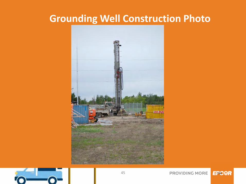
45
Grounding Well Construction Photo
164
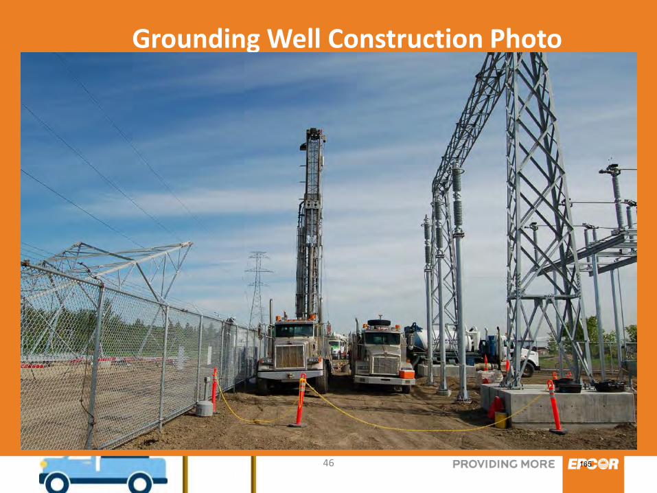
46
Grounding Well Construction Photo
165
47
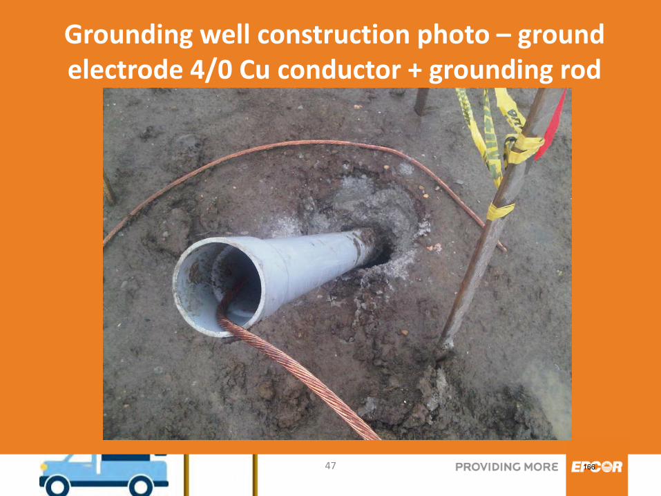
Grounding well construction photo – ground electrode 4/0 Cu conductor + grounding rod
166

48
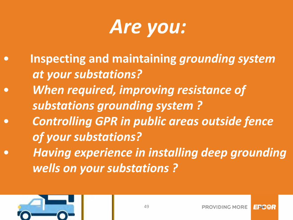
Questions to you!
167
49
• Inspecting and maintaining grounding system at your substations? • When required, improving resistance of substations grounding system ? • Controlling GPR in public areas outside fence of your substations? • Having experience in installing deep grounding wells on your substations ?
Are you:
168
50
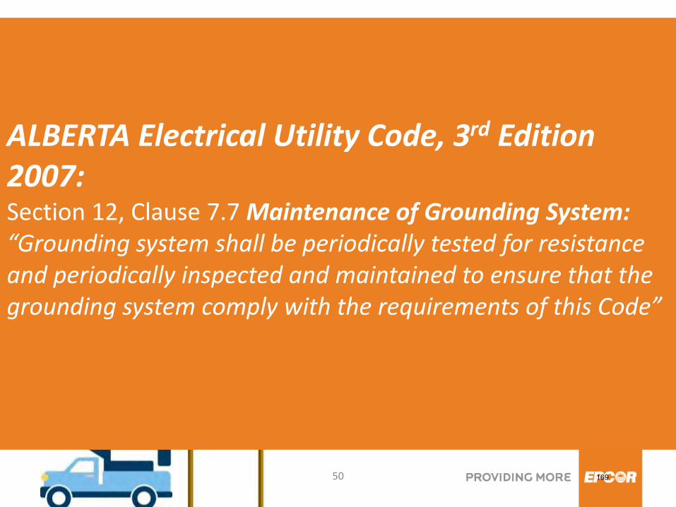
ALBERTA Electrical Utility Code, 3rd Edition 2007: Section 12, Clause 7.7 Maintenance of Grounding System: “Grounding system shall be periodically tested for resistance and periodically inspected and maintained to ensure that the grounding system comply with the requirements of this Code”
169
51
Paper: DEEP EARTH GROUNDING vs SHALLOW EARTH GROUNDING by Martin D. Conroy and Paul G. Richard, Computer Power Corporation, Omaha, Nebraska Westinghouse: Electrical Transmission and Distribution Reference Book IEEE- 80, Guide for Safety in AC Substation Grounding IEEE – 81, Guide for Measuring Earth Resistivity, Ground Impedance, and Earth Surface Potentials of a Ground System IEEE – 81.2, Guide for Measurement of Impendance and Safety Characteristics of Large, Extended or Interconnected Grounding System IEEE – 367, Recommended Practice for Determining the Electric Power Station Ground Potential Rise and Induced Voltage From Power Fault AEUC – Alberta Electrical Utility Code Fluke 1625 and Megger DET-2-2 tester’s manuals CANA – HTI : EPCOR Poundmaker Substation Grounding Study Report
References:
170

52
Thank you !
171
1
Case Study
Characteristics of GPR as Affected by Grounding Structures
University of Alberta
by Wilsun Xu
University of Alberta May 2013
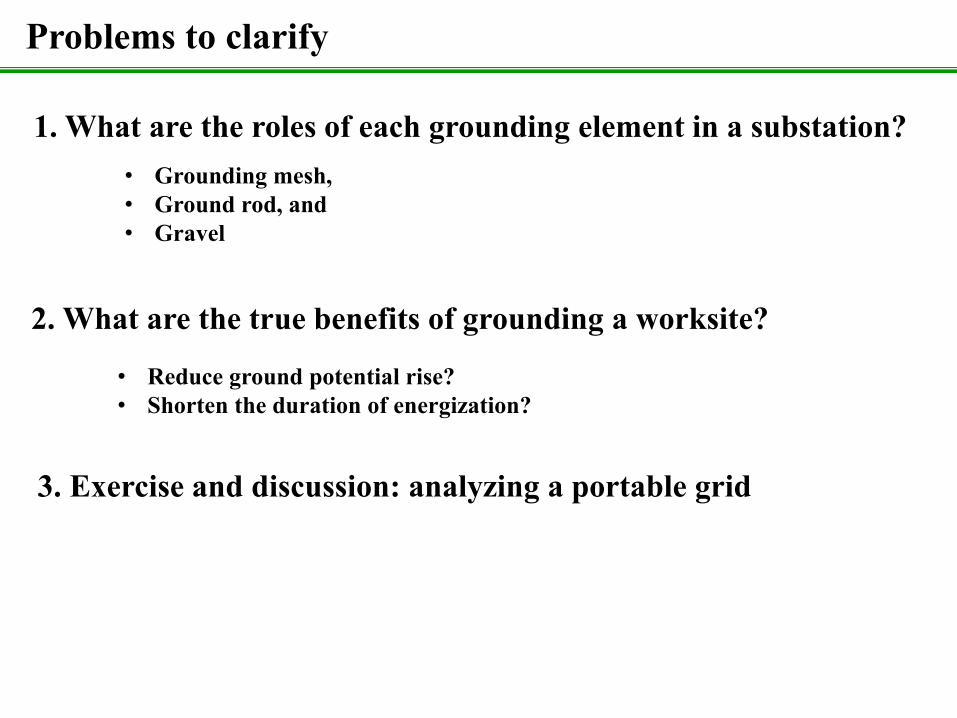
Problems to clarify
1. What are the roles of each grounding element in a substation? • Grounding mesh, • Ground rod, and • Gravel
3. Exercise and discussion: analyzing a portable grid
2. What are the true benefits of grounding a worksite?
• Reduce ground potential rise? • Shorten the duration of energization?
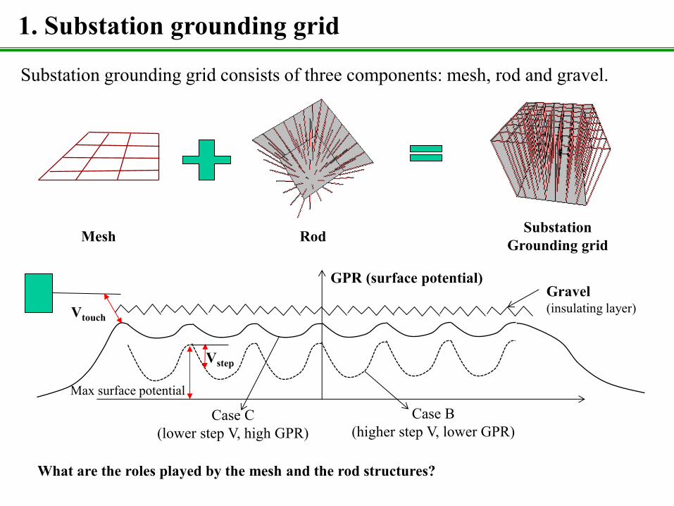
1. Substation grounding grid
Mesh Rod Substation Grounding grid
Substation grounding grid consists of three components: mesh, rod and gravel.
GPR (surface potential) Gravel (insulating layer)
What are the roles played by the mesh and the rod structures?
Case C (lower step V, high GPR)
Case B (higher step V, lower GPR)
Vstep
Vtouch
Max surface potential
Zsystem Vs
Rg
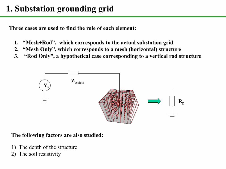
Three cases are used to find the role of each element:
1. “Mesh+Rod”, which corresponds to the actual substation grid 2. “Mesh Only”, which corresponds to a mesh (horizontal) structure 3. “Rod Only”, a hypothetical case corresponding to a vertical rod structure
1. Substation grounding grid
The following factors are also studied: 1) The depth of the structure 2) The soil resistivity
1. Substation grounding grid
0 0.2 0.4 0.6 0.8 1 1.2 1.4 1.6 1.8 20
10
20
30
40
50
60
70
80
90
100
Distance [m]
Vol
tage
Pot
entia
l
t=0mt=0.5mt=1mt=1.5mt=2m
t=0m
t=2m
t=1mt=1.5m
t=0.5m
0 0.2 0.4 0.6 0.8 1 1.2 1.4 1.6 1.8 20
10
20
30
40
50
60
70
80
90
100
Distance [m]
Vol
tage
Pro
tent
ial
t=0.01mt=0.5mt=1mt=1.5mt=2m
t=0.01m
t=0.5m
t=1.0m
t=1.5m
t=2m
Y
Z
X Vx (x,0,0)x
L
L/2
t
(0,0,-t)
YZ
X
dz
L
Vx (x,0,0)
(0,0,-L/2-t)
(0,0,z)
d
t
Vertical Rod
Horizontal Rod
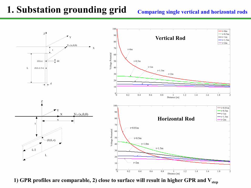
1) GPR profiles are comparable, 2) close to surface will result in higher GPR and Vstep
Comparing single vertical and horizontal rods
1. Substation grounding grid Compare grounding structures
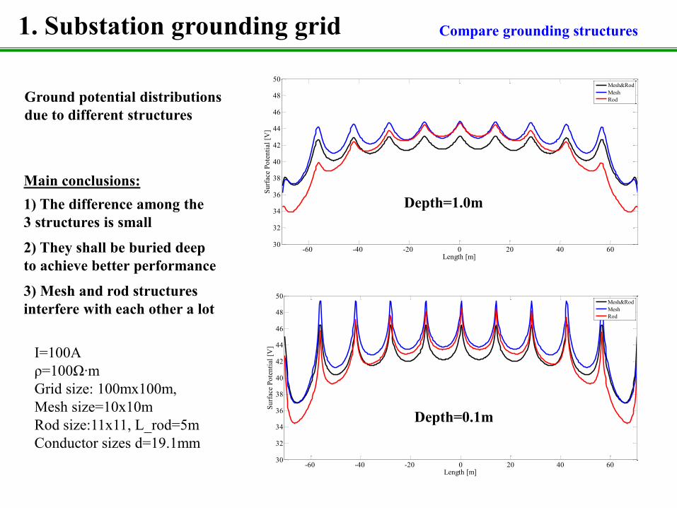
I=100A ρ=100Ω∙m Grid size: 100mx100m, Mesh size=10x10m Rod size:11x11, L_rod=5m Conductor sizes d=19.1mm
-60 -40 -20 0 20 40 6030
32
34
36
38
40
42
44
46
48
50
Length [m]Su
rfac
e Po
tent
ial [
V]
Mesh&RodMeshRod
-60 -40 -20 0 20 40 6030
32
34
36
38
40
42
44
46
48
50
Length [m]
Surf
ace
Pote
ntia
l [V
]
Mesh&RodMeshRod
Ground potential distributions due to different structures
Depth=1.0m
Depth=0.1m
Main conclusions: 1) The difference among the 3 structures is small
2) They shall be buried deep to achieve better performance
3) Mesh and rod structures interfere with each other a lot
-60 -40 -20 0 20 40 600
10
20
30
40
50
60
70
80
90
100
Length [m]
Surf
ace
Pote
ntia
l [V
]
Mesh&RodMeshRod
-60 -40 -20 0 20 40 600
10
20
30
40
50
60
70
80
90
100
Length [m]Su
rface
Pot
entia
l [V
]
Mesh&RodMeshRod
1. Substation grounding grid Impact of soil
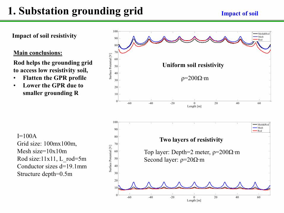
I=100A Grid size: 100mx100m, Mesh size=10x10m Rod size:11x11, L_rod=5m Conductor sizes d=19.1mm Structure depth=0.5m
Uniform soil resistivity
Impact of soil resistivity
Two layers of resistivity
Top layer: Depth=2 meter, ρ=200Ω∙m Second layer: ρ=20Ω∙m
Main conclusions: Rod helps the grounding grid to access low resistivity soil, • Flatten the GPR profile • Lower the GPR due to smaller grounding R
ρ=200Ω∙m
-60 -40 -20 0 20 40 6030
35
40
45
50
55
60
Length [m]
Surf
ace
Pote
ntia
l [V
]
Mesh&RodMeshRod
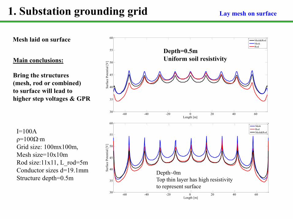
Depth=0.5m Uniform soil resistivity
1. Substation grounding grid Lay mesh on surface
Main conclusions:
Bring the structures (mesh, rod or combined) to surface will lead to higher step voltages & GPR
-60 -40 -20 0 20 40 60 30
35
40
45
50
55
60
Length [m]
Surf
ace
Pote
ntia
l [V
]
MeshRodMesh&Rod
Depth~0m Top thin layer has high resistivity to represent surface
Mesh laid on surface
I=100A ρ=100Ω∙m Grid size: 100mx100m, Mesh size=10x10m Rod size:11x11, L_rod=5m Conductor sizes d=19.1mm Structure depth=0.5m
1. Substation grounding grid Summary of findings
Main findings:
The vertical (rod) and horizontal (mesh) structures are almost equally effective. However, the rod structure can reach deep soil with lower resistivity, leading to more significant reduction on GPR and step voltages;
The depth of grounding structure has a significant impact on the surface potential, in the form of GPR and step voltage. If the structure is closer to the surface, higher GPR and step voltage will result;
The vertical (rod) and horizontal (mesh) structures interfere with each other heavily. Combined use of the two structures does not double the performance. They act more like backups to each other;
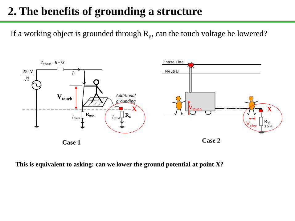
2. The benefits of grounding a structure
If a working object is grounded through Rg, can the touch voltage be lowered?
25kV
Zsystem=R+jX
If
3
Rmat Rg
Additional
grounding
IFmat IFrod
P h a se L in e
N e u tr a l
U n g r o u n d
R g
5 0ΩV s te p
V to u ch
S tif fle g s
Phase Line
Neutral
Grounding to Temp. Rod
Rg
15ΩVstep
V touch
(a) Ungrounded scheme (b) Grounding to temporary rod
Phase Line
Neutral
Rg
15Ω
Grounding to Perm. Rod
Vstep
V touch
Phase Line
Neutral
Rg
15Ω
Grounding to Neutral
Vstep
V touch
(c) Grounding to system rod (d) Grounding to system neutral
Vtouch
Case 1 Case 2
X X
This is equivalent to asking: can we lower the ground potential at point X?
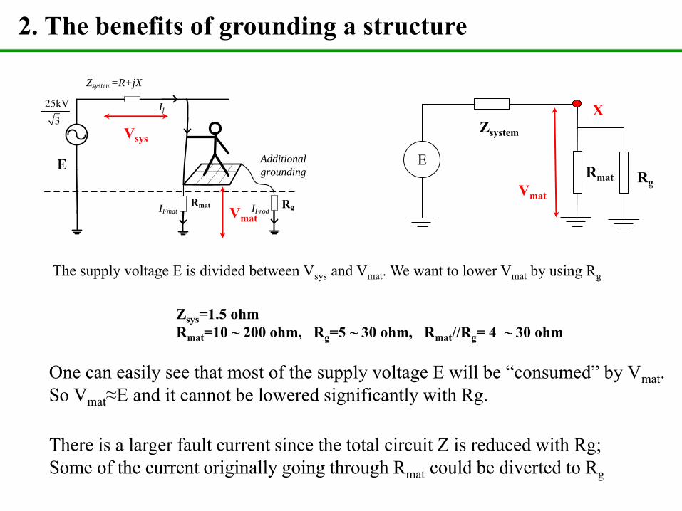
2. The benefits of grounding a structure
25kV
Zsystem=R+jX
If
3
Rmat Rg
Additional
grounding
IFmat IFrod
E
Vsys
Vmat
The supply voltage E is divided between Vsys and Vmat. We want to lower Vmat by using Rg
Zsys=1.5 ohm Rmat=10 ~ 200 ohm, Rg=5 ~ 30 ohm, Rmat//Rg= 4 ~ 30 ohm
One can easily see that most of the supply voltage E will be “consumed” by Vmat. So Vmat≈E and it cannot be lowered significantly with Rg.
There is a larger fault current since the total circuit Z is reduced with Rg; Some of the current originally going through Rmat could be diverted to Rg
E
Zsystem
Rmat
X
Rg Vmat
2. The benefits of grounding a structure
P h a se L in e
N e u tr a l
U n g r o u n d
R g
5 0ΩV s te p
V to u ch
S tif fle g s
Phase Line
Neutral
Grounding to Temp. Rod
Rg
15ΩVstep
V touch
(a) Ungrounded scheme (b) Grounding to temporary rod
Phase Line
Neutral
Rg
15Ω
Grounding to Perm. Rod
Vstep
V touch
Phase Line
Neutral
Rg
15Ω
Grounding to Neutral
Vstep
V touch
(c) Grounding to system rod (d) Grounding to system neutral
X
E
Zsystem
Rg
X
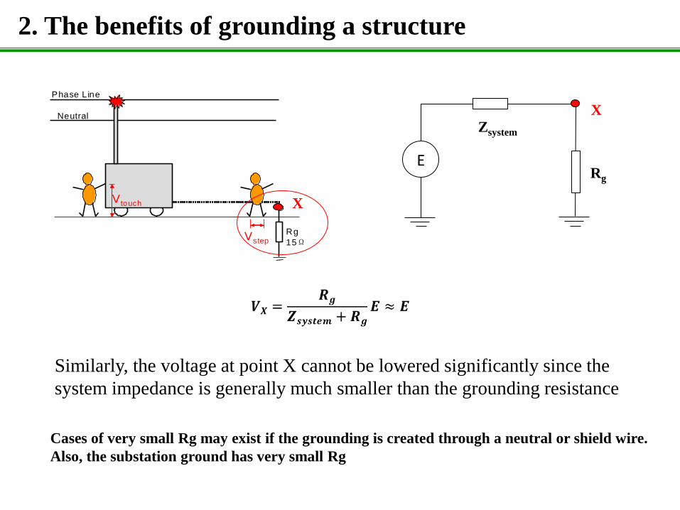
Similarly, the voltage at point X cannot be lowered significantly since the
system impedance is generally much smaller than the grounding resistance
Cases of very small Rg may exist if the grounding is created through a neutral or shield wire.
Also, the substation ground has very small Rg
2. The benefits of grounding a structure
Main findings:
Grounding, however, can result in a larger fault current, leading to fast fault clearing and reduced GPR duration; Grounding can divert some fault currents from a structure, making the structure experience reduced fault current;
Grounding does not guarantee a significant reduction on the GPR, since the grounding resistance is often higher than the system impedance. A large portion of the system voltage will impose on the grounding resistance; The energizing source behaves as a voltage source. Grounding can help to reduce GPR if the grounding resistance approaches the level of system impedance, examples are ground to system neutral or substation; The energizing source behaves as a current source.
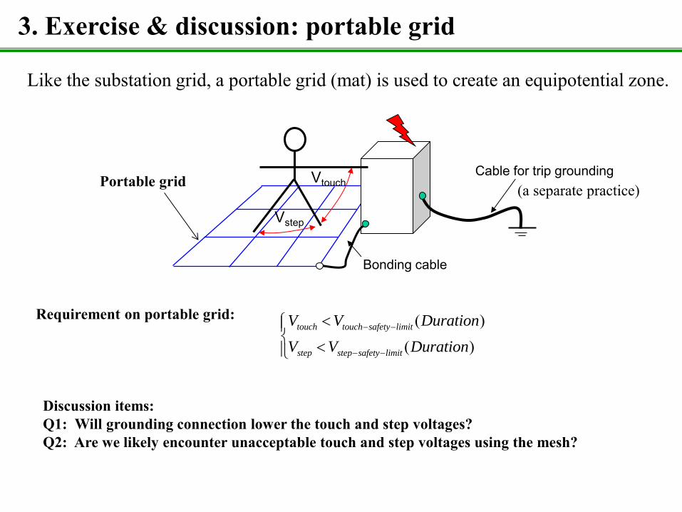
3. Exercise & discussion: portable grid
Vtouch
Vstep
Bonding cable
Cable for trip grounding (a separate practice)
Like the substation grid, a portable grid (mat) is used to create an equipotential zone.
Portable grid
( )( )
touch touch safety limit
step step safety limit
V V Duration
V V Duration
Requirement on portable grid:
Discussion items: Q1: Will grounding connection lower the touch and step voltages? Q2: Are we likely encounter unacceptable touch and step voltages using the mesh?
Vtouch
Vstep
Bonding cable
Cable for trip grounding Ideal grid (Metal plate) (a separate practice)
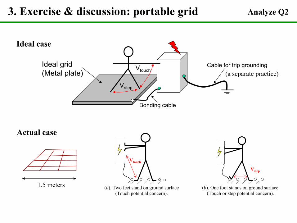
3. Exercise & discussion: portable grid
Ideal case
Actual case
(a). Two feet stand on ground surface
(Touch potential concern). (b). One foot stands on ground surface
(Touch or step potential concern).
Vtouch
Vstep
1.5 meters
Analyze Q2
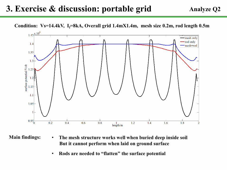
Condition: Vs=14.4kV, If=8kA, Overall grid 1.4mX1.4m, mesh size 0.2m, rod length 0.5m
3. Exercise & discussion: portable grid Analyze Q2
• The mesh structure works well when buried deep inside soil But it cannot perform when laid on ground surface
Main findings:
• Rods are needed to “flatten” the surface potential
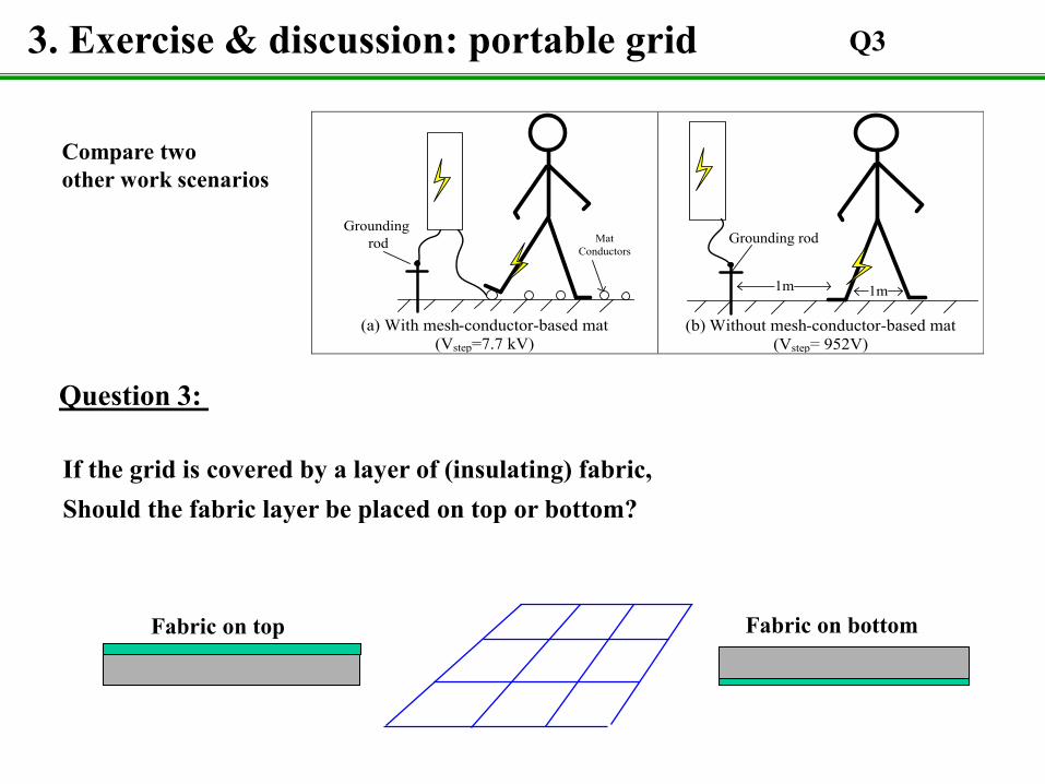
If the grid is covered by a layer of (insulating) fabric, Should the fabric layer be placed on top or bottom?
Fabric on top Fabric on bottom
3. Exercise & discussion: portable grid Q3
Question 3:
Mat Conductors
Grounding rod
(a) With mesh-conductor-based mat
(Vstep=7.7 kV)
Grounding rod
1m 1m
(b) Without mesh-conductor-based mat (Vstep= 952V)
Compare two other work scenarios
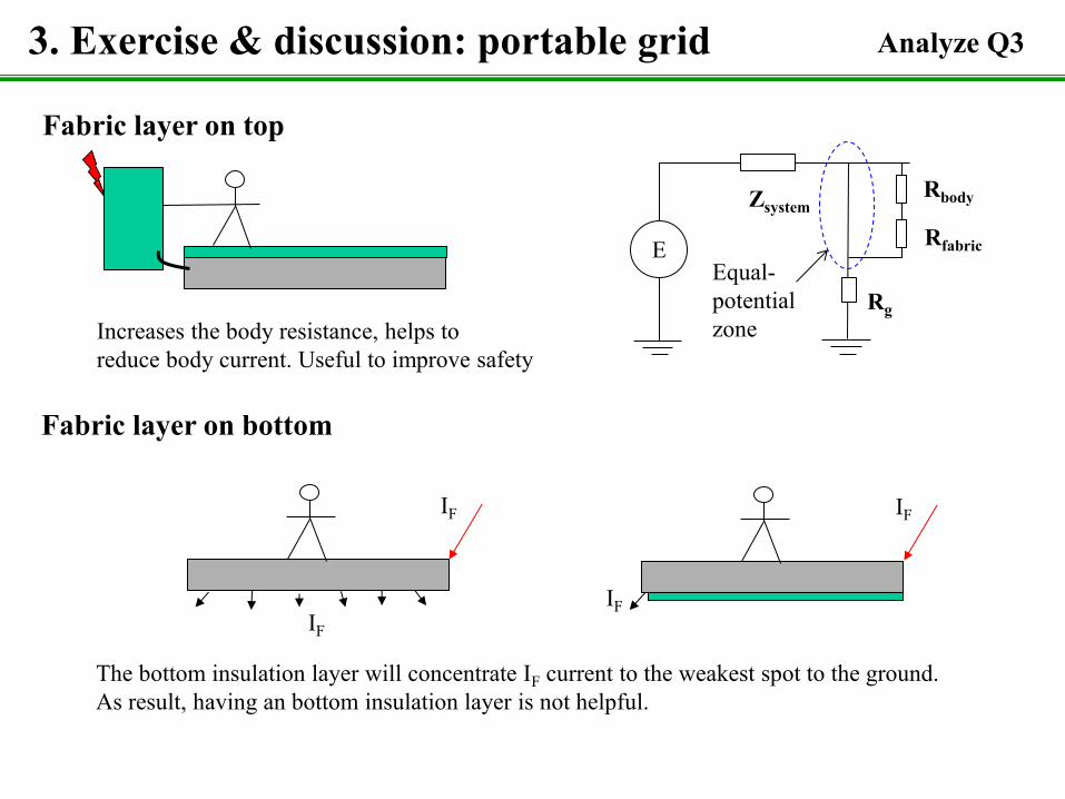
Fabric layer on top
Increases the body resistance, helps to reduce body current. Useful to improve safety
Fabric layer on bottom
IF IF
IF
IF
The bottom insulation layer will concentrate IF current to the weakest spot to the ground. As result, having an bottom insulation layer is not helpful.
3. Exercise & discussion: portable grid
E
Zsystem
Rg
Rfabric
Rbody
Equal- potential zone
Analyze Q3
Theory
Measurement of Grounding Conditions
University of Alberta
by Wilsun Xu
University of Alberta May 2013
190
Outline
• Measurement of grounding resistance
• Measurement of soil resistivity
• Measurement of touch and step voltages
• Factors affecting grounding resistance and GPR
• Online monitoring of substation grounding grid
191
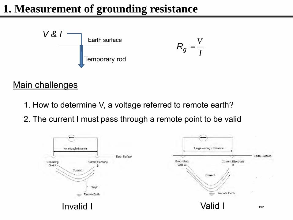
1. Measurement of grounding resistance
VRI
=V & I
Earth surface
Main challenges
1. How to determine V, a voltage referred to remote earth?
Rg
2. The current I must pass through a remote point to be valid
Invalid I Valid I
Temporary rod
192
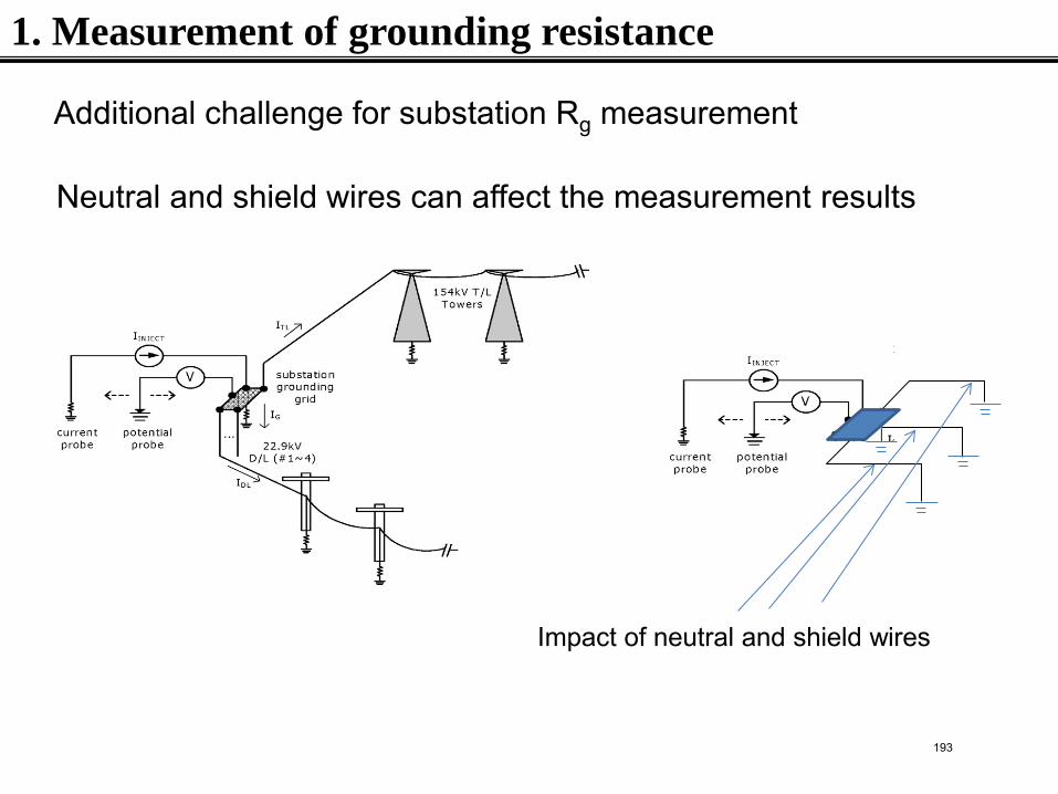
Neutral and shield wires can affect the measurement results
Impact of neutral and shield wires
1. Measurement of grounding resistance
Additional challenge for substation Rg measurement
193
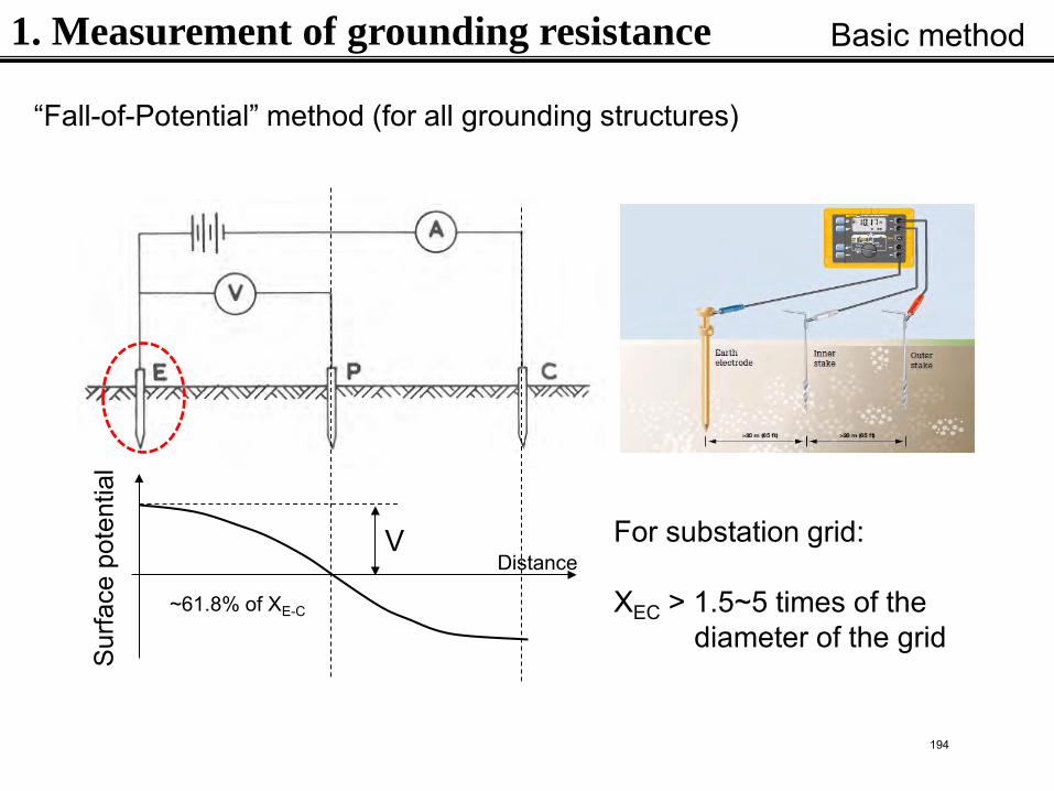
“Fall-of-Potential” method (for all grounding structures) S
urfa
ce p
oten
tial
Distance V
~61.8% of XE-C
For substation grid: XEC > 1.5~5 times of the diameter of the grid
1. Measurement of grounding resistance Basic method
194
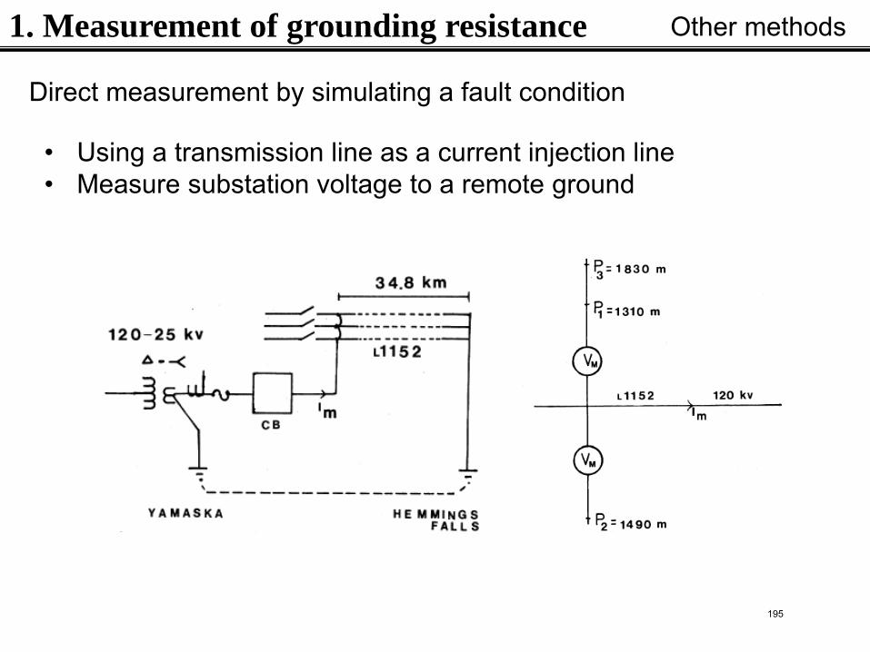
1. Measurement of grounding resistance Other methods
• Using a transmission line as a current injection line • Measure substation voltage to a remote ground
Direct measurement by simulating a fault condition
195
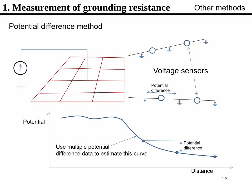
1. Measurement of grounding resistance Other methods
Potential difference method
Voltage sensors
Potential difference
Distance
Potential
Potential difference Use multiple potential
difference data to estimate this curve
196
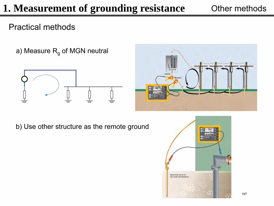
Practical methods
a) Measure Rg of MGN neutral
b) Use other structure as the remote ground
1. Measurement of grounding resistance Other methods
197
9
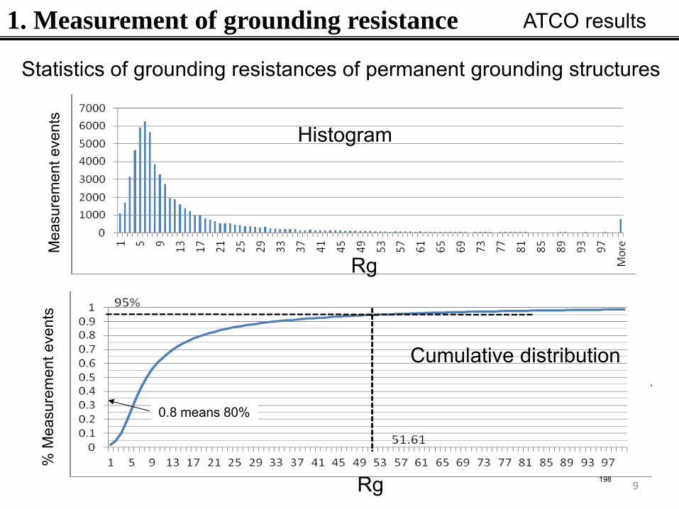
1. Measurement of grounding resistance ATCO results
Statistics of grounding resistances of permanent grounding structures
Histogram
Cumulative distribution
Rg
Rg
Mea
sure
men
t eve
nts
% M
easu
rem
ent e
vent
s
0.8 means 80%
198
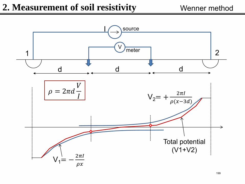
2. Measurement of soil resistivity
V
source
meter
I
d d d
Total potential (V1+V2)
1 2
Wenner method
199
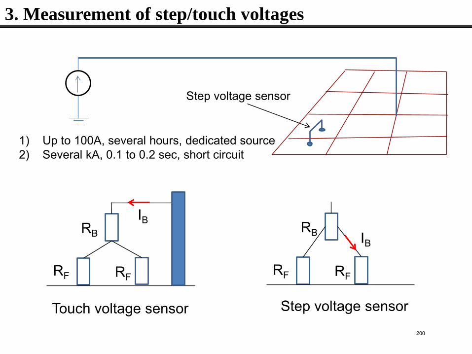
3. Measurement of step/touch voltages
1) Up to 100A, several hours, dedicated source 2) Several kA, 0.1 to 0.2 sec, short circuit
Step voltage sensor
RF RF
RB
IB
RF RF
RB IB
Touch voltage sensor Step voltage sensor
200
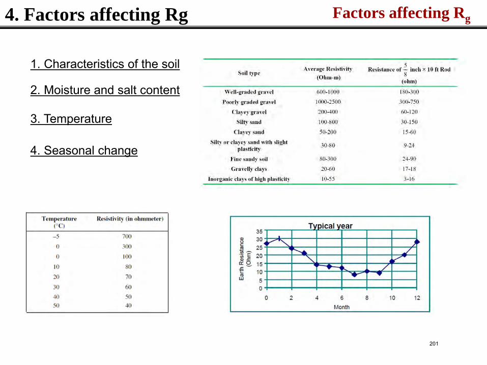
4. Factors affecting Rg Factors affecting Rg
2. Moisture and salt content
3. Temperature
4. Seasonal change
1. Characteristics of the soil
201
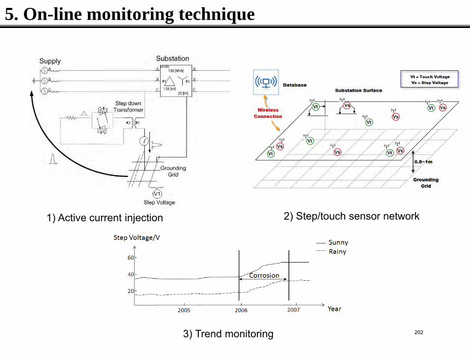
5. On-line monitoring technique
1) Active current injection 2) Step/touch sensor network
3) Trend monitoring 202
6. Summary
• Grounding condition measurement is still difficult to perform, due to 1) the need for multiple independent electrodes, 2) the impact of various natural factors
• The existing measurement methods just provide a snapshot of the grounding condition. Interpretation of the grounding performance under other conditions is needed
• On-line, continuous monitoring approaches seem to be the future for ground condition monitoring
203
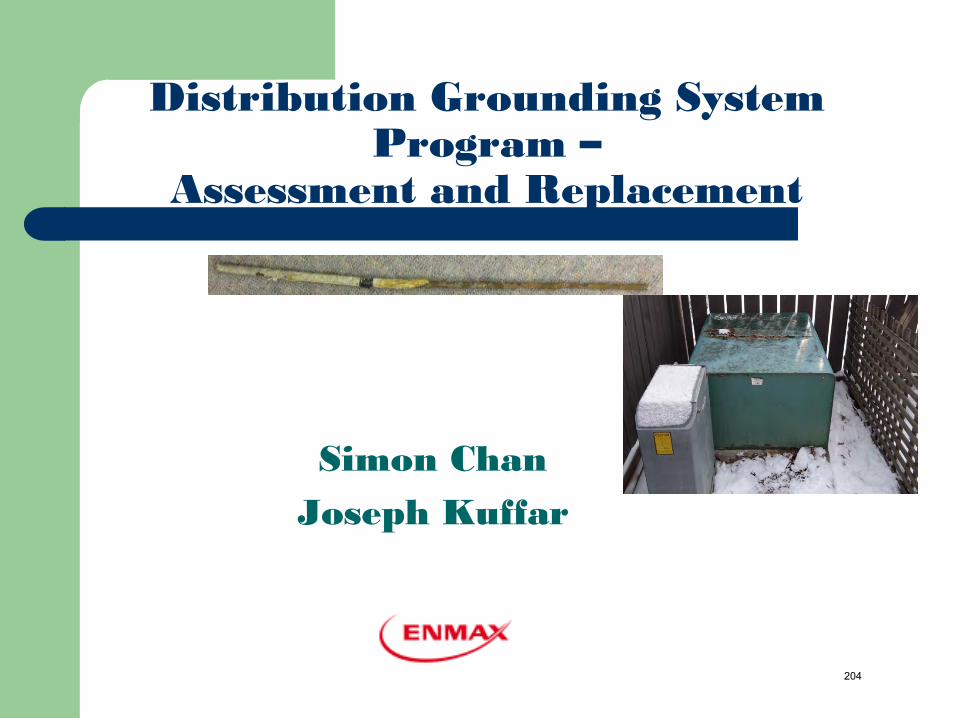
Distribution Grounding System Program –
Assessment and Replacement
Simon Chan Joseph Kuffar
204
Outline
Background Drivers Ground Testing Program Grounding Replacement Program
205
Background
In 2004, UMS Group reviewed EPC Proactive Asset Replacement Program.
Study compared EPC to North American utility industry as well as global best practices.
Recommended EPC to initiate a Ground Integrity Testing program
206
Background..
Practice of the time….. Initial Installation test Maintenance test
– Proactive – In conjunction with Pole Testing and Treatment Program (O/H system only)
– Reactive – abnormal report (both O/H and U/G) Grounding replacement
– Reactive replacement - abnormal report – Pole replacement program
Paper records
207
Drivers
Equipment Protection To provides a low resistance path ground as well as
discharge path for lightning energy To allow proper operation of protective equipment during
the fault
Personnel Safety To Maintains equipment and other grounded structures at
the potential of earth To Minimize the risks of step and touch potential
Regulatory compliance
208
Drivers..
Regulatory Requirements: the 2003 Alberta Electric Utilities Act (Section 105 (1)):
– The owner of an electric distribution system has the following duties: – “(c) to operate and maintain the electric distribution system in a safe and reliable
manner”.
the 2007 Alberta Electrical and Utility Code Section 12 Grounding : Clause 7.6 Corrosion of Grounding System
(2) If the cross section area or mass of the grounding system equipment has been reduced by corrosion to less than 80% of the amount required by this Code the equipment shall be replaced.
– Clause 7.7 Maintenance of Grounding System Grounding systems shall be periodically tested for resistance and periodically inspected
and maintained to ensure that the grounding systems comply with the requirements of this Code.
209
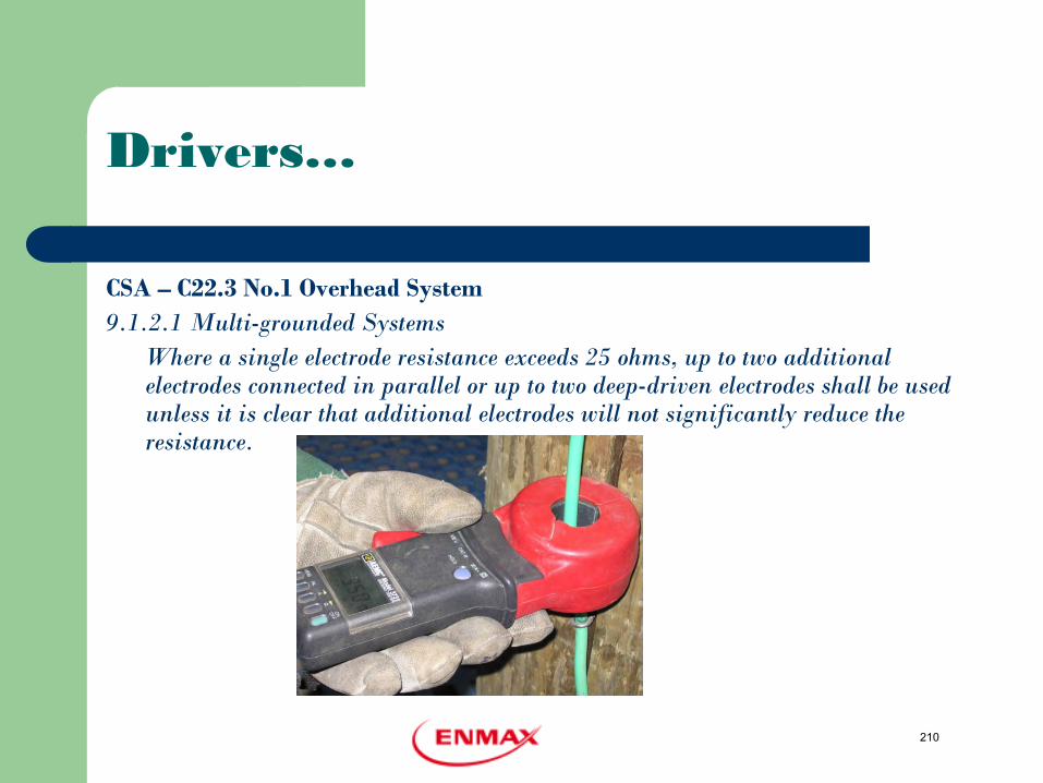
Drivers…
CSA – C22.3 No.1 Overhead System 9.1.2.1 Multi-grounded Systems Where a single electrode resistance exceeds 25 ohms, up to two additional
electrodes connected in parallel or up to two deep-driven electrodes shall be used unless it is clear that additional electrodes will not significantly reduce the resistance.
210
2006 Grounding Testing Program
EPC initiated a 3 year grounding test program Work performed by consultant Purpose
– Establish an accurate overall ground rod condition for both O/H and U/G system
– Create a centralized database for record keeping – Implement a structured maintenance program
211
Fall 2006 Testing
Tested the grounding systems for 39 distribution feeders (randomly selected).
Sample selection as per ANSI/ASQ Z1.4 Standard Test limited to O/H and U/G dead-front equipment Pass/Failure Value of 25 ohms was used Started late Sept 2006 and completed Nov 2006 Data captured and stored in CMMS
212
Fall 2006 Testing - Tool
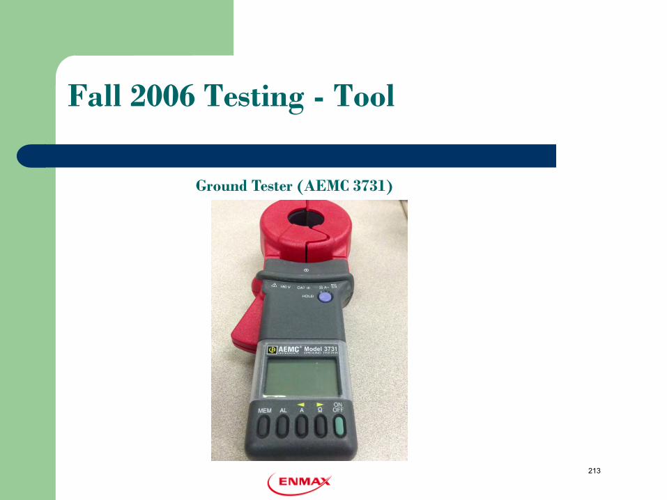
Ground Tester (AEMC 3731)
213
Fall 2006 Testing - Results
1099 of 7351 Distribution Ground Rods Tested 332 Failed (30%) 30% Pass/Fail Criteria – 17 Feeders failed Most failures were on old installations - 20 years plus
214
Fall 2006 Testing - Results ..
Questions 1. What is our typical Soil Condition? 2. How bad (severity of Deterioration)? 3. Should we change the approach? 4. What is the mode of failure (connectors or rods)? 5. Should we established a pass/fail criteria based on
the actual soil condition?
215
Fall 2006 Testing -Recommendation
Collect Soil Conditions/Resistivity Data with each ground rod resistance measurement
Determine the mode of failure - field Verification Test the remaining ground rods on feeders that failed
216
Outcome
Revised approach 2007 -2008 Testing based on age Work issued by city section Test area selected covered most areas of the city Measurements included Soil resistivity and grounding
resistance Test sites selected as per ANSI/ASQ Z1.4 Standard
217
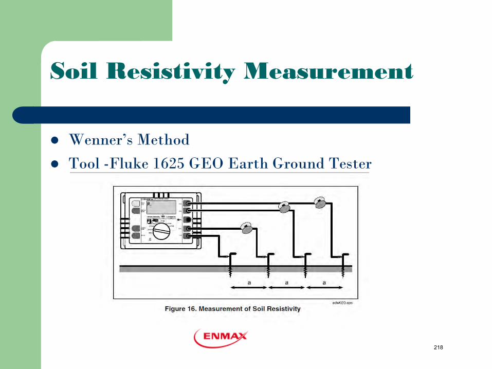
Soil Resistivity Measurement
Wenner’s Method Tool -Fluke 1625 GEO Earth Ground Tester
218
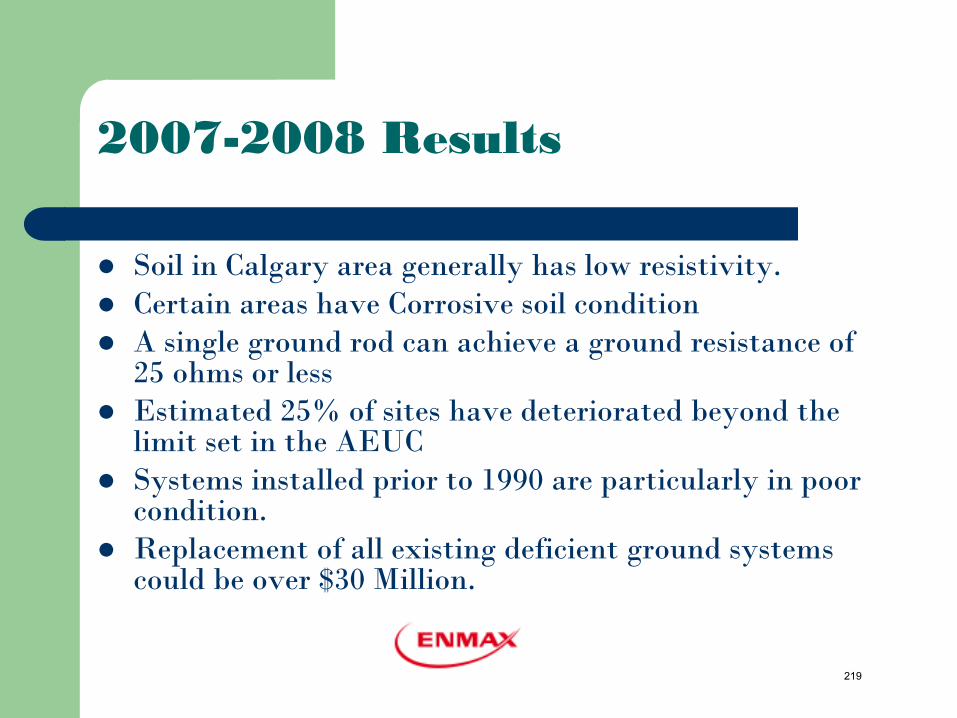
2007-2008 Results
Soil in Calgary area generally has low resistivity. Certain areas have Corrosive soil condition A single ground rod can achieve a ground resistance of
25 ohms or less Estimated 25% of sites have deteriorated beyond the
limit set in the AEUC Systems installed prior to 1990 are particularly in poor
condition. Replacement of all existing deficient ground systems
could be over $30 Million.
219
2007-2008 Results -Key Understanding
- Understand typical soil conditions in Calgary - Identify areas with corrosive soil - Establish a pass/failure based on soil condition - Project the level of deterioration for field verification - Prioritize the replacement program
220
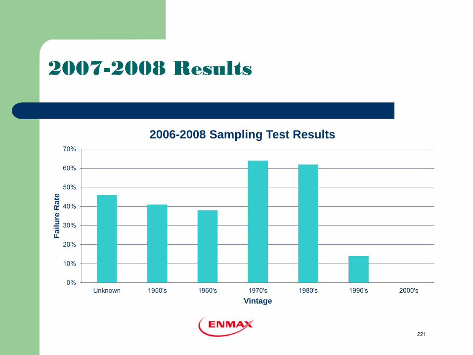
0%
10%
20%
30%
40%
50%
60%
70%
Unknown 1950's 1960's 1970's 1980's 1990's 2000's
Failu
re R
ate
Vintage
2006-2008 Sampling Test Results
2007-2008 Results
221
Field Trial 2009-2011
Objectives: – Small scale project to assess and determine the course
of addressing the entire EPC grounding system. – Further refine the number of deficient sites – Assess the replacement costs per site – Verify the projected level of deterioration – Identify any resource or other concerns likely to occur
in a full scale replacement program
222
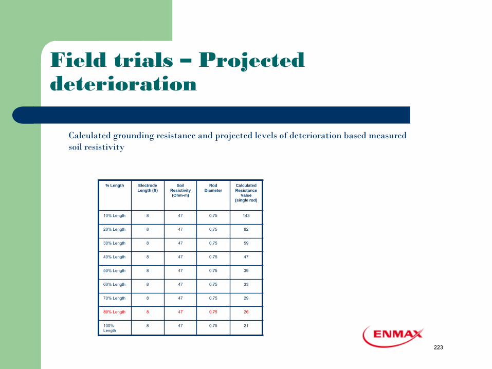
Field trials – Projected deterioration
% Length Electrode Length (ft)
Soil Resistivity (Ohm-m)
Rod Diameter
Calculated Resistance
Value (single rod)
10% Length 8 47 0.75 143
20% Length 8 47 0.75 82
30% Length 8 47 0.75 59
40% Length 8 47 0.75 47
50% Length 8 47 0.75 39
60% Length 8 47 0.75 33
70% Length 8 47 0.75 29
80% Length 8 47 0.75 26
100% Length
8 47 0.75 21
Calculated grounding resistance and projected levels of deterioration based measured soil resistivity
223
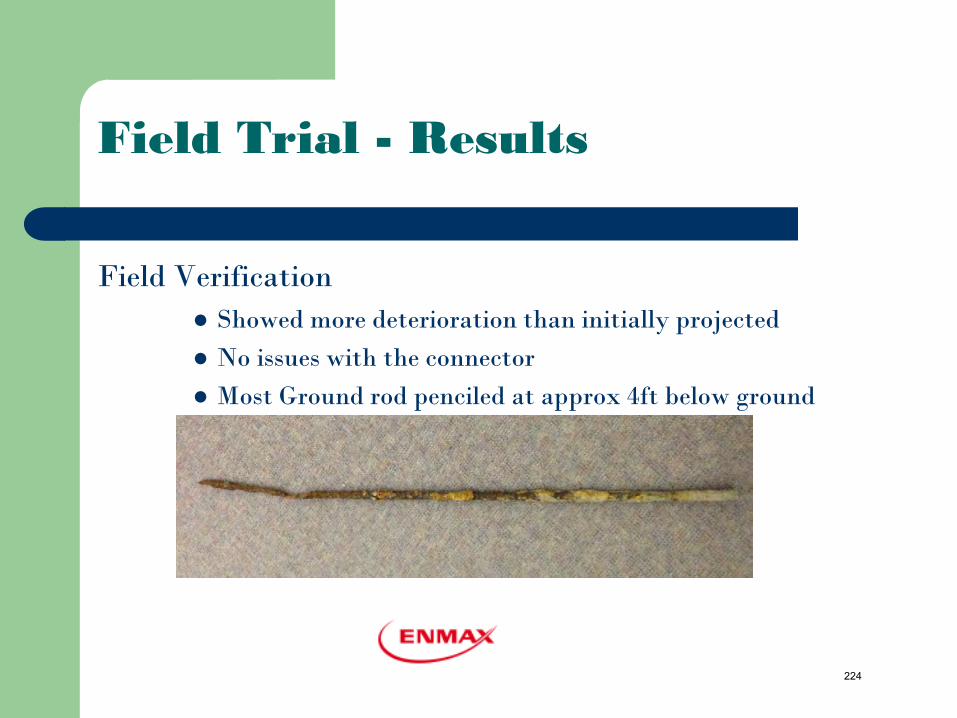
Field Trial - Results
Field Verification Showed more deterioration than initially projected No issues with the connector Most Ground rod penciled at approx 4ft below ground
224
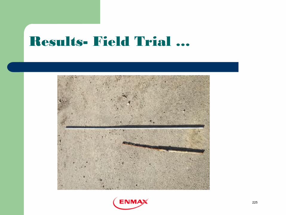
Results- Field Trial …
225
Grounding Replacement Program
In 2012, ENMAX Initiated grounding replacement program.
– Targeting areas with high failure rate – Priority given to areas with UJKT Cables – Installation based on current standard – Hydrovac excavation
226
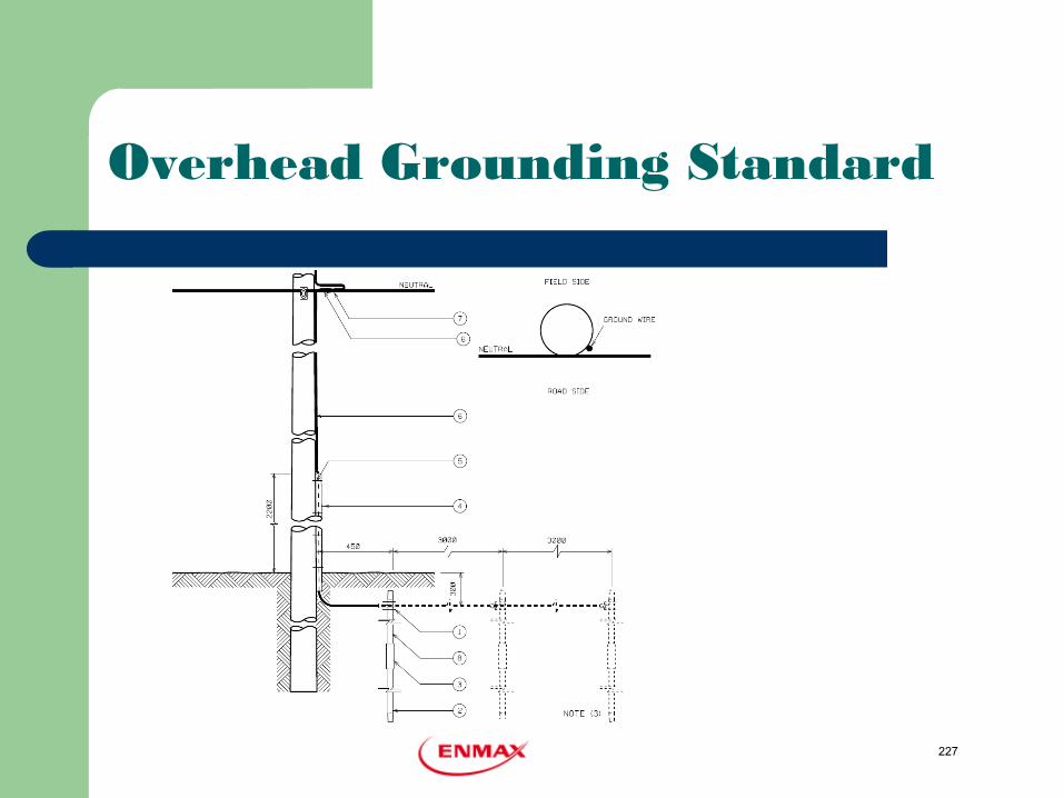
Overhead Grounding Standard
227
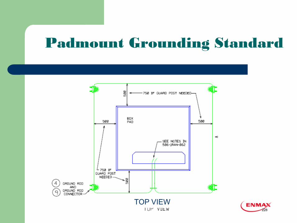
Padmount Grounding Standard
TOP VIEW 228
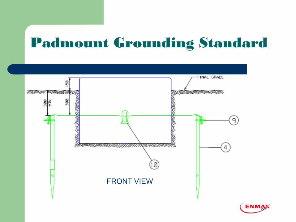
Padmount Grounding Standard
FRONT VIEW
229
Current Practice..
Current Maintenance practice Initial Installation test Maintenance test
– O/H- In conjunction with Pole Testing and Treatment Program (10-year Cycle)
– UG – in conjunction with Line inspection
Maintenance record captured in CMMS system
230
Current Practice….
Replacement Upgrade the grounding when
– Section of cable is replaced – Old equipments are replaced – High resistance grounds are identified – Other system upgrades program
Sections with high failure rate are targeted for proactive replacement program
231
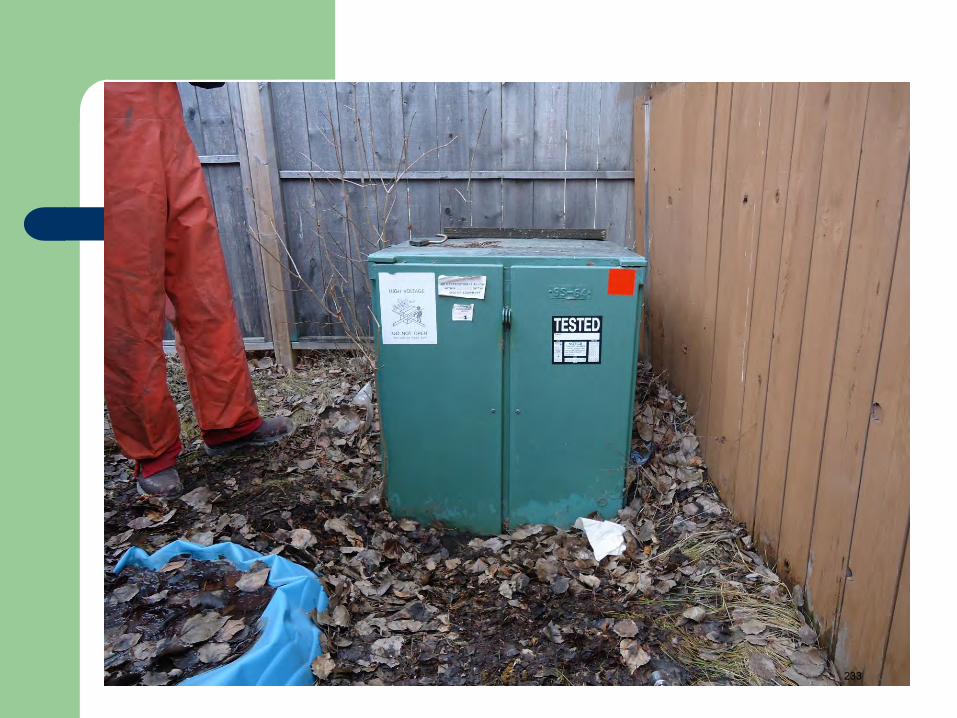
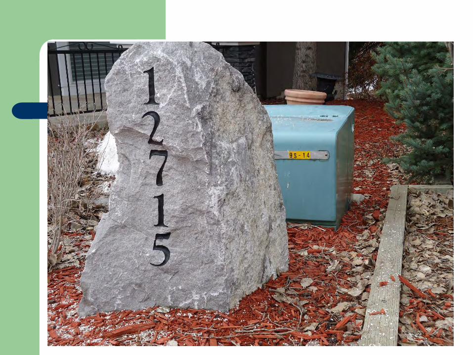
Challenges
Equipments on Private Property (backyard…) Equipment in less accessible areas Equipment on paved lanes Easement Encroachment - fences, garages & etc Resources Customer Complaints
232
233
234
235
Reference
Alberta Electrical Utility Code, 3rd Edition 2007 CSA – C22.3 No.1 Overhead System ANSI/ASQ Z1.4 Standard Fluke 1625 User manual
236
Questions
237
1
Theory & Case Study
Connecting Substation and Feeder Neutrals: Pros, Cons and ATCO Practice
University of Alberta
by Wilsun Xu
University of Alberta May 2013
238
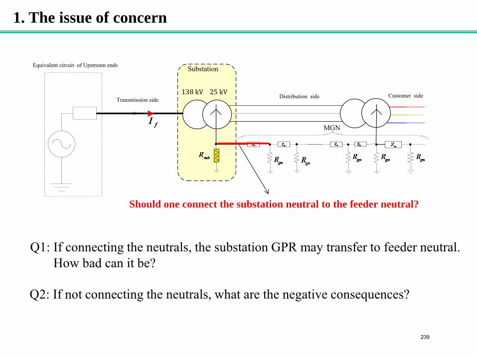
1. The issue of concern
138 kV
Substation
MGN
25 kV Transmission side Distribution side Customer side
///
Equivalent circuit of Upstream ends
Should one connect the substation neutral to the feeder neutral?
Q1: If connecting the neutrals, the substation GPR may transfer to feeder neutral. How bad can it be?
Q2: If not connecting the neutrals, what are the negative consequences?
239
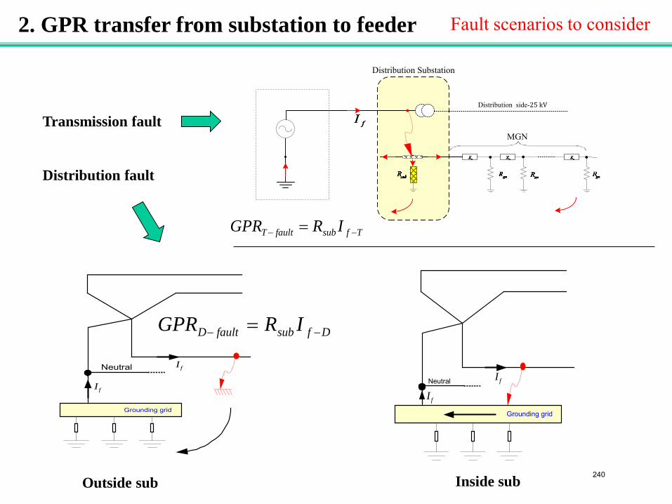
2. GPR transfer from substation to feeder
Distribution Substation
MGN
Distribution side-25 kV
Fault scenarios to consider
Neutral
Grounding grid
fI
fI
Neutral
Grounding grid
fIfI
Transmission fault Distribution fault
Outside sub Inside sub
TfsubfaultT IRGPR −− =
DfsubfaultD IRGPR −− =
240
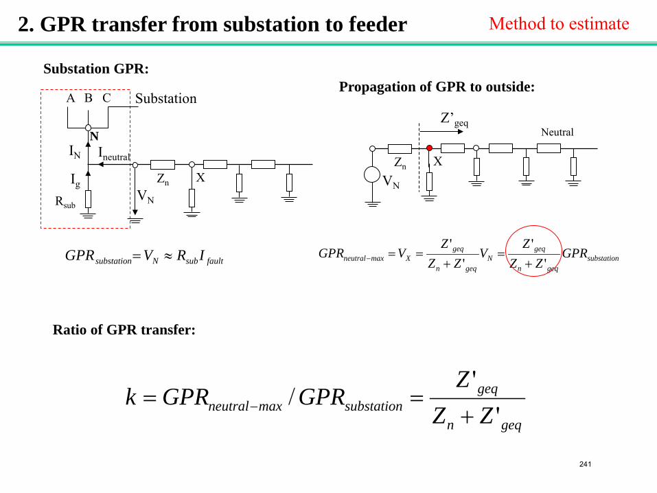
Rsub
Z’geq A B C Substation
N
Zn Ig
Ineutral IN
X VN
faultsubNsubstation IRVGPR ≈=
Neutral
Zn X VN
Substation GPR: Propagation of GPR to outside:
substationgeqn
geqN
geqn
geqXmaxneutral GPR
ZZZ
VZZ
ZVGPR
''
''
+=
+==−
geqn
geqsubstationmaxneutral ZZ
ZGPRGPRk
''
/+
== −
Ratio of GPR transfer:
2. GPR transfer from substation to feeder Method to estimate
241
0
2
4
6
8
10
12
14
16
0 0.5 1 1.5 2Neutral length [km]
Equ
ivle
nt im
ped.
[ohm
]
Z’geq
ZN
Zgn
ZN
Zgn Zgn
ZN Z’geq
0.7
0.8
0.9
1
7 15( base case) 30
Grounding resisatnce [Ω]
[/
]
S=50m S=100m (base case) S=250m S=500m
Ratio of GPR transfer
K
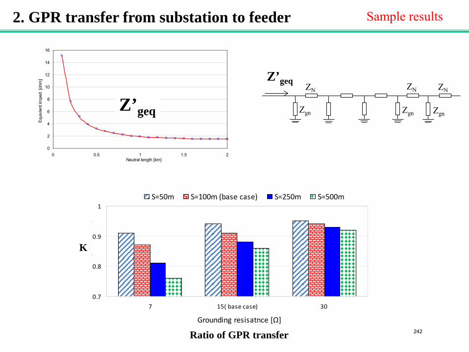
2. GPR transfer from substation to feeder Sample results
242
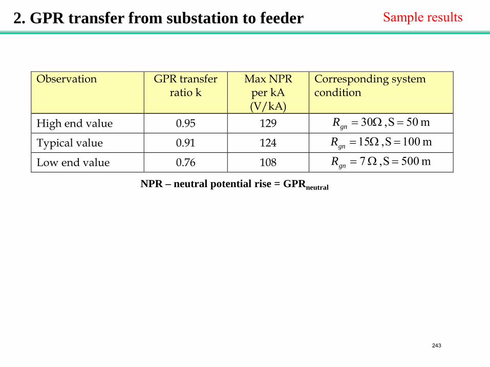
2. GPR transfer from substation to feeder Sample results
Observation GPR transfer ratio k
Max NPR per kA (V/kA)
Corresponding system condition
High end value 0.95 129 m 50S, 30 =Ω=gnR
Typical value 0.91 124 m 001S, 15 =Ω=gnR
Low end value 0.76 108 m 500S, 7 =Ω=gnR NPR – neutral potential rise = GPRneutral
243
gnRgnRgnRgnR
nZ n nZnZ nZ nZ nZmaxNPR
GPRgnR
Customer #1 Customer #2
2NPR NNPR
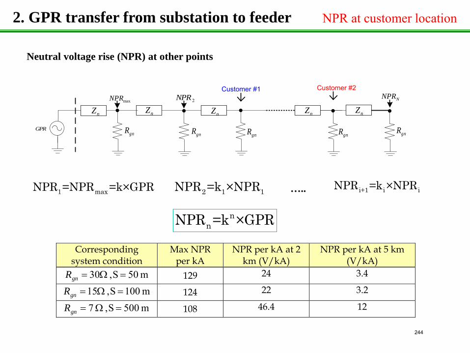
Neutral voltage rise (NPR) at other points
1 maxNPR =NPR =k×GPR 2 1 1NPR =k ×NPR i+1 i iNPR =k ×NPR
nnNPR =k ×GPR
…..
Corresponding system condition
Max NPR per kA
NPR per kA at 2 km (V/kA)
NPR per kA at 5 km (V/kA)
m 50S, 30 =Ω=gnR 129 24 3.4
m 001S, 15 =Ω=gnR 124 22 3.2
m 500S, 7 =Ω=gnR 108 46.4 12
2. GPR transfer from substation to feeder NPR at customer location
244
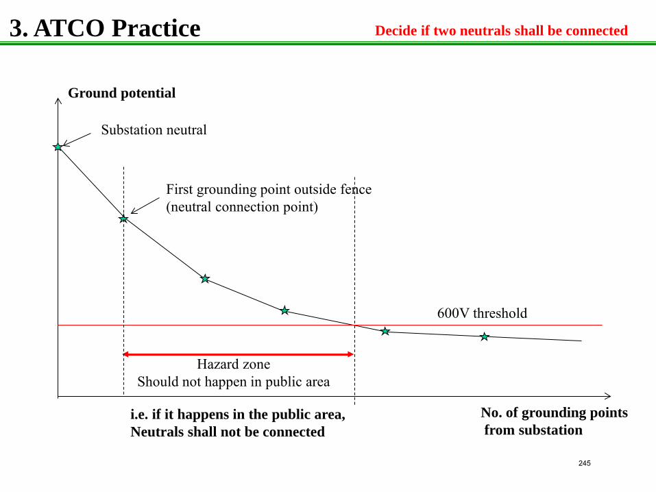
3. ATCO Practice
Ground potential
No. of grounding points from substation
Substation neutral
First grounding point outside fence (neutral connection point)
600V threshold
Hazard zone Should not happen in public area
i.e. if it happens in the public area, Neutrals shall not be connected
Decide if two neutrals shall be connected
245
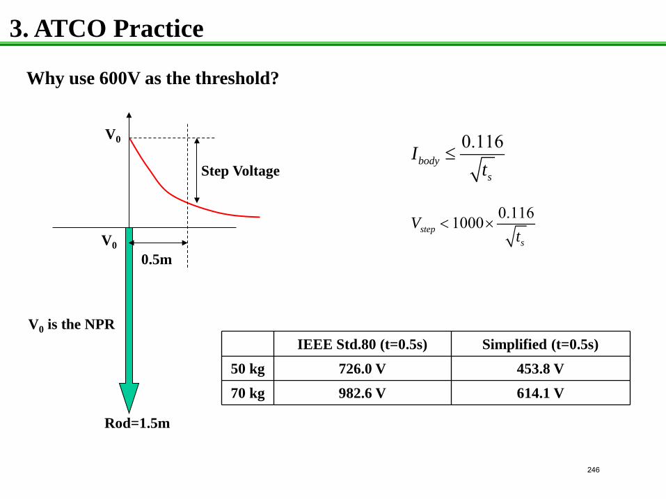
3. ATCO Practice
Why use 600V as the threshold?
V0
0.5m
Step Voltage
V0
V0 is the NPR
0.116body
s
It
≤
0.1161000steps
Vt
< ×
IEEE Std.80 (t=0.5s) Simplified (t=0.5s)
50 kg 726.0 V 453.8 V
70 kg 982.6 V 614.1 V
Rod=1.5m
246
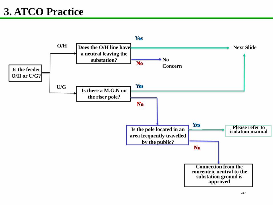
3. ATCO Practice
Is the feeder O/H or U/G?
O/H
Is there a M.G.N on the riser pole?
Does the O/H line have a neutral leaving the
substation?
Is the pole located in an area frequently travelled
by the public?
Connection from the concentric neutral to the
substation ground is approved
Please refer to isolation manual
No Concern
U/G
Next Slide
247
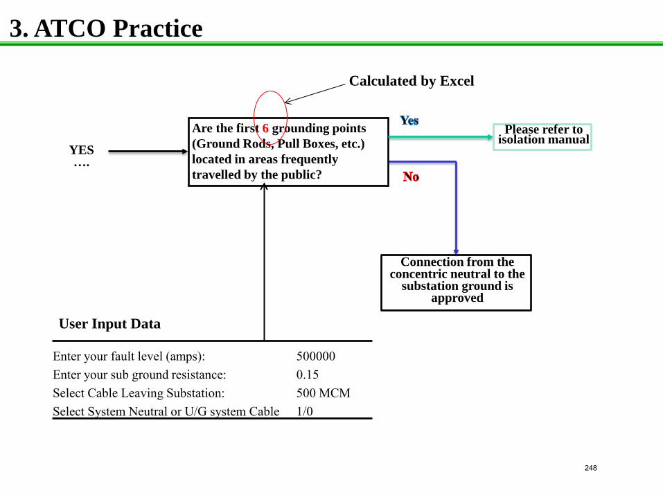
3. ATCO Practice
Connection from the concentric neutral to the
substation ground is approved
Enter your fault level (amps): 500000 Enter your sub ground resistance: 0.15 Select Cable Leaving Substation: 500 MCM Select System Neutral or U/G system Cable 1/0
Are the first 6 grounding points (Ground Rods, Pull Boxes, etc.) located in areas frequently travelled by the public?
Please refer to isolation manual
YES ….
User Input Data
Calculated by Excel
248
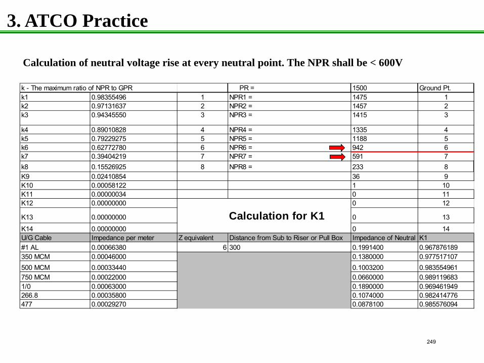
3. ATCO Practice
k - The maximum ratio of NPR to GPR PR = 1500 Ground Pt.k1 0.98355496 1 NPR1 = 1475 1k2 0.97131637 2 NPR2 = 1457 2k3 0.94345550 3 NPR3 = 1415 3
k4 0.89010828 4 NPR4 = 1335 4k5 0.79229275 5 NPR5 = 1188 5k6 0.62772780 6 NPR6 = 942 6k7 0.39404219 7 NPR7 = 591 7k8 0.15526925 8 NPR8 = 233 8K9 0.02410854 36 9K10 0.00058122 1 10K11 0.00000034 0 11K12 0.00000000 0 12
K13 0.00000000 Calculation for K1 0 13
K14 0.00000000 0 14U/G Cable Impedance per meter Z equivalent Distance from Sub to Riser or Pull Box Impedance of Neutral K1#1 AL 0.00066380 6 300 0.1991400 0.967876189350 MCM 0.00046000 0.1380000 0.977517107500 MCM 0.00033440 0.1003200 0.983554961750 MCM 0.00022000 0.0660000 0.9891196831/0 0.00063000 0.1890000 0.969461949266.8 0.00035800 0.1074000 0.982414776477 0.00029270 0.0878100 0.985576094
Calculation of neutral voltage rise at every neutral point. The NPR shall be < 600V
249
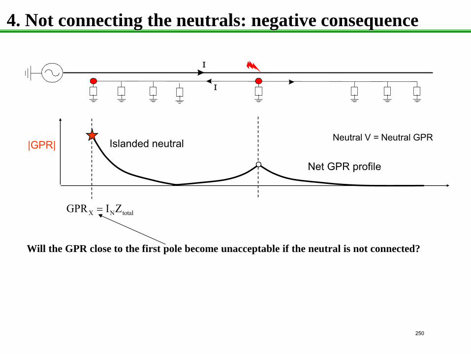
4. Not connecting the neutrals: negative consequence
X N totalGPR I Z=
|GPR|
Net GPR profile
Islanded neutral
I
I
Neutral V = Neutral GPR
Will the GPR close to the first pole become unacceptable if the neutral is not connected?
250
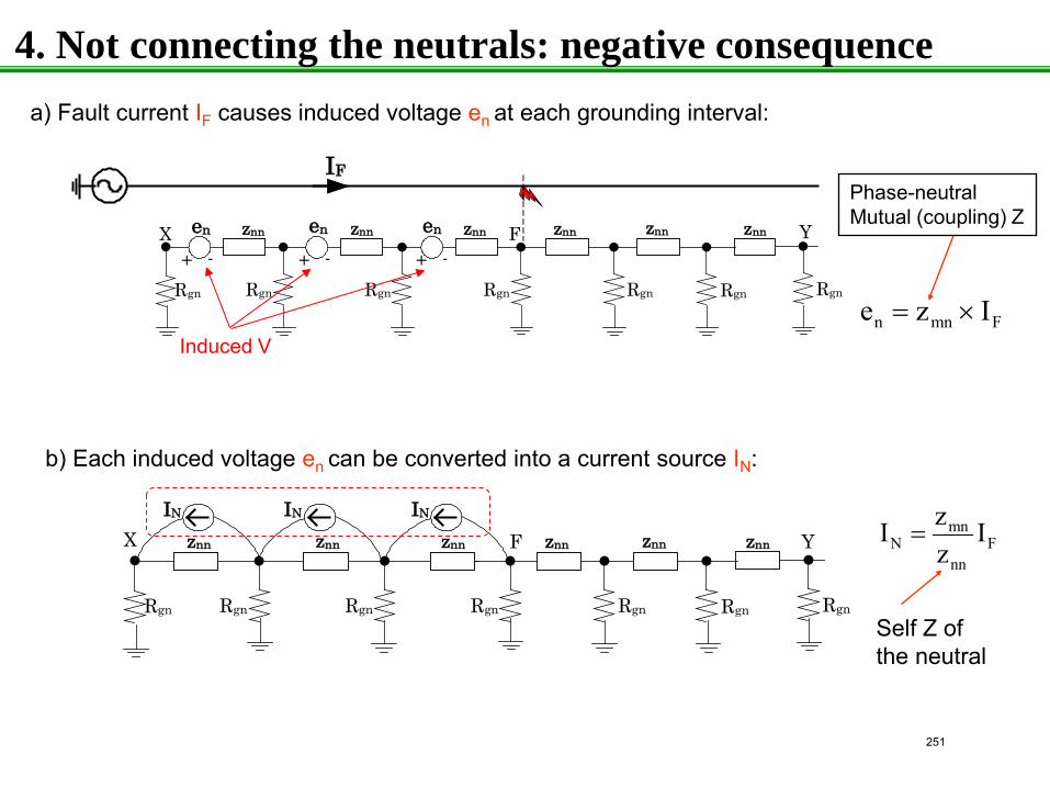
IF
znn
RgnRgn Rgn Rgn Rgn RgnRgn
znn znn znn znn znnen en en
+ - + - + -X YF
znn
RgnRgn Rgn Rgn Rgn RgnRgn
znn znn znn znn znn
IN IN IN
X YF
a) Fault current IF causes induced voltage en at each grounding interval:
n mn Fe z I= ×
Phase-neutral Mutual (coupling) Z
b) Each induced voltage en can be converted into a current source IN:
mnN F
nn
zI Iz
=
Self Z of the neutral
Induced V
4. Not connecting the neutrals: negative consequence
251
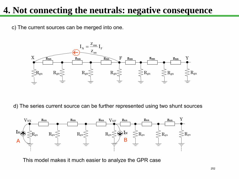
z n n
R g n R gn R g n R g n R g n R g n R g n
z n n z n n z n n z n n z n n X Y F
c) The current sources can be merged into one.
d) The series current source can be further represented using two shunt sources
A B
mnN F
nn
zI Iz
=
z n n V NX Y
I N R g n R gn I N R g n R g n R g n R g n R g n
z n n z n n z n n z n n z n n V NF
This model makes it much easier to analyze the GPR case
4. Not connecting the neutrals: negative consequence
252
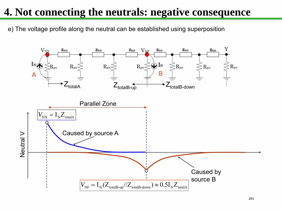
Parallel Zone
Neu
tral V
Caused by source B
Caused by source A
NX N totalAI ZV =
NF N totalB-up totalB-down N totalAI (Z //Z ) 0.5I ZV = ≈
e) The voltage profile along the neutral can be established using superposition
A B
z n n V NX Y
I N R g n R gn I N R g n R g n R g n R g n R g n
z n n z n n z n n z n n z n n V NF
ZtotalA ZtotalB-up ZtotalB-down
4. Not connecting the neutrals: negative consequence
253
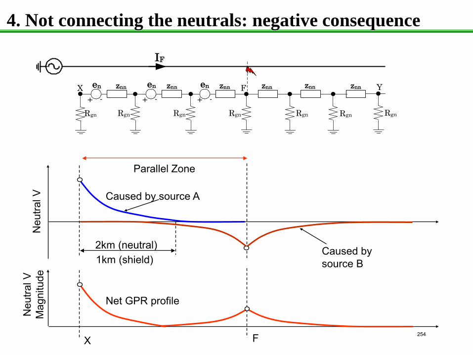
Parallel Zone
Caused by source B
Caused by source A
Net GPR profile
2km (neutral) 1km (shield)
X F
Neu
tral V
N
eutra
l V
Mag
nitu
de
IF
znn
RgnRgn Rgn Rgn Rgn RgnRgn
znn znn znn znn znnen en en
+ - + - + -X YF
4. Not connecting the neutrals: negative consequence
254
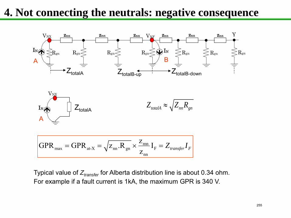
A
V NX
I N
A B
z n n V NX Y
I N R g n R gn I N R g n R g n R g n R g n R g n
z n n z n n z n n z n n z n n V NF
ZtotalA ZtotalB-up ZtotalB-down
ZtotalA totalA nn gnZ Z R≈
mnmax at-X nn gn F
nn
zGPR GPR z .R Iz transfer FZ I= = × =
Typical value of Ztransfer for Alberta distribution line is about 0.34 ohm. For example if a fault current is 1kA, the maximum GPR is 340 V.
4. Not connecting the neutrals: negative consequence
255
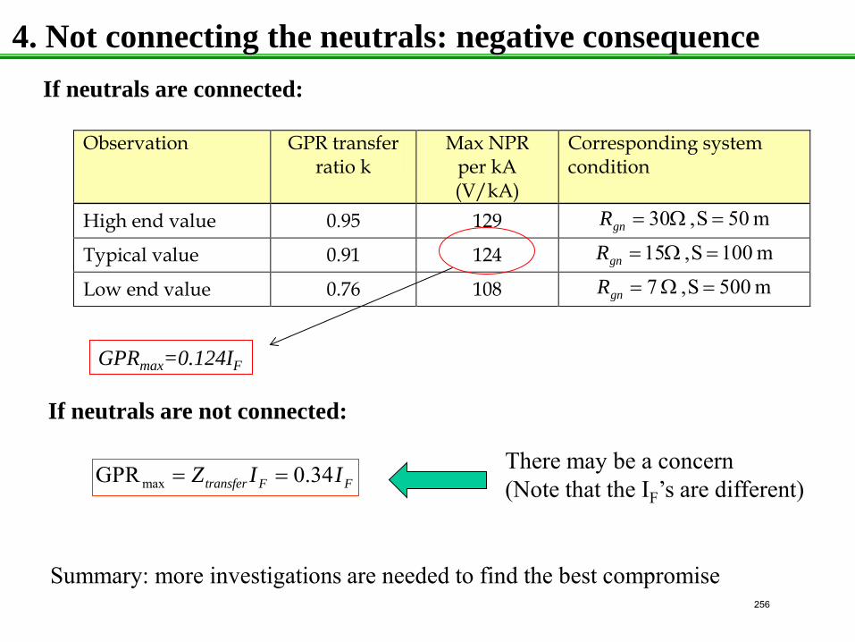
maxGPR 0.34transfer F FZ I I= =
If neutrals are not connected:
If neutrals are connected:
Observation GPR transfer ratio k
Max NPR per kA (V/kA)
Corresponding system condition
High end value 0.95 129 m 50S, 30 =Ω=gnR
Typical value 0.91 124 m 001S, 15 =Ω=gnR
Low end value 0.76 108 m 500S, 7 =Ω=gnR
There may be a concern (Note that the IF’s are different)
GPRmax=0.124IF
Summary: more investigations are needed to find the best compromise
4. Not connecting the neutrals: negative consequence
256
1
Case Study
Does improving grounding help to reduce telephone interference ?
University of Alberta
by Wilsun Xu
University of Alberta May 2013
257
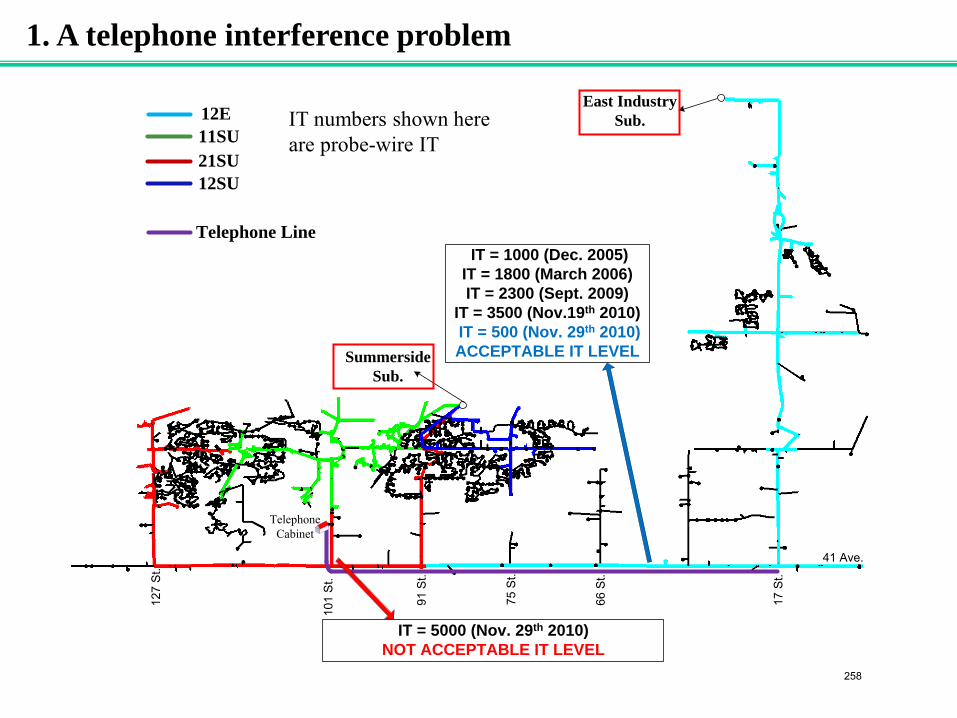
1. A telephone interference problem
Summerside Sub.
East Industry Sub.12E
11SU21SU12SU
Telephone Line
Telephone Cabinet
41 Ave.
17 S
t.
66 S
t.
75 S
t.
101
St.
91 S
t.
127
St.
IT = 1000 (Dec. 2005)IT = 1800 (March 2006)IT = 2300 (Sept. 2009)
IT = 3500 (Nov.19th 2010) IT = 500 (Nov. 29th 2010)ACCEPTABLE IT LEVEL
IT = 5000 (Nov. 29th 2010)NOT ACCEPTABLE IT LEVEL
IT numbers shown here are probe-wire IT
258
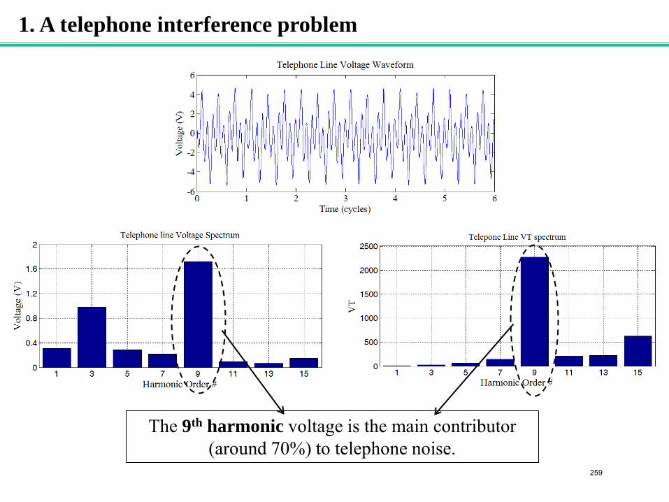
The 9th harmonic voltage is the main contributor (around 70%) to telephone noise.
1. A telephone interference problem
259
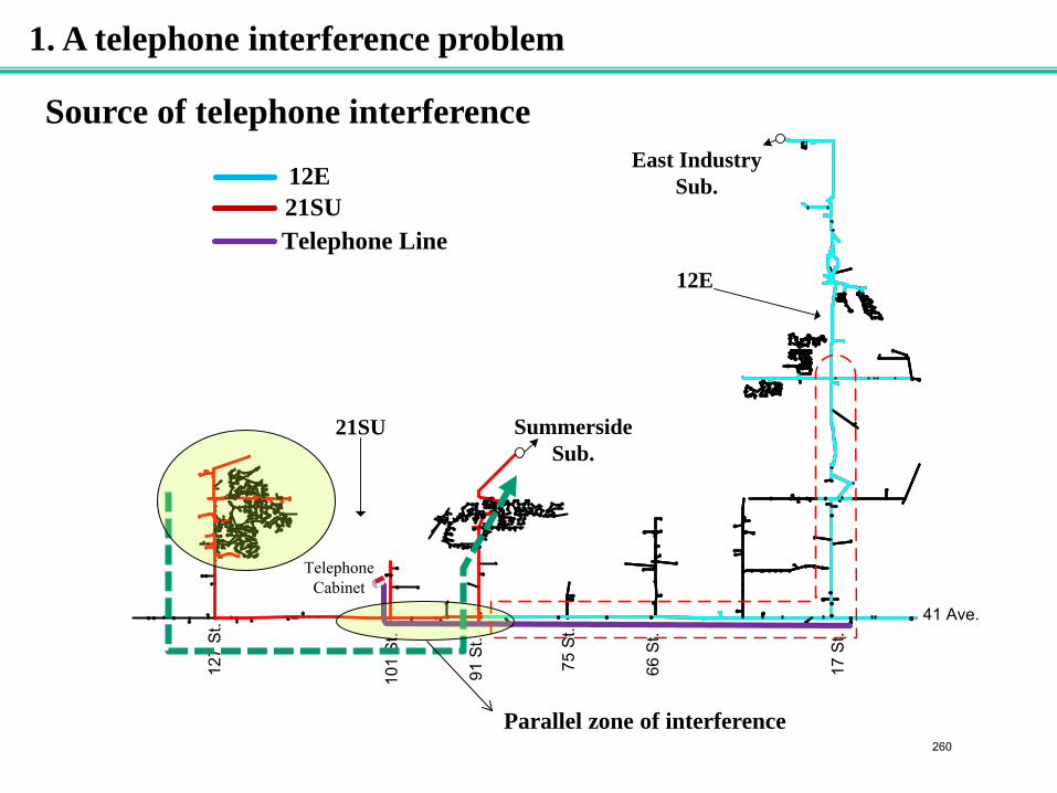
Telephone Cabinet
Summerside Sub.
East Industry Sub.
12E
21SU
41 Ave.
75 S
t.
101
St.
91 S
t.
127
St.
17 S
t.
66 S
t.
12E21SUTelephone Line
1. A telephone interference problem
Source of telephone interference
Parallel zone of interference 260
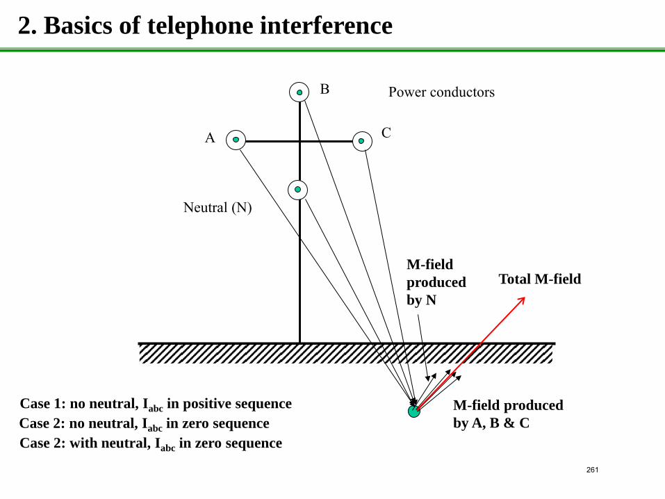
B Power conductors
Neutral (N)
A C
M-field produced by A, B & C
M-field produced by N
2. Basics of telephone interference
Total M-field
Case 1: no neutral, Iabc in positive sequence Case 2: no neutral, Iabc in zero sequence Case 2: with neutral, Iabc in zero sequence
261
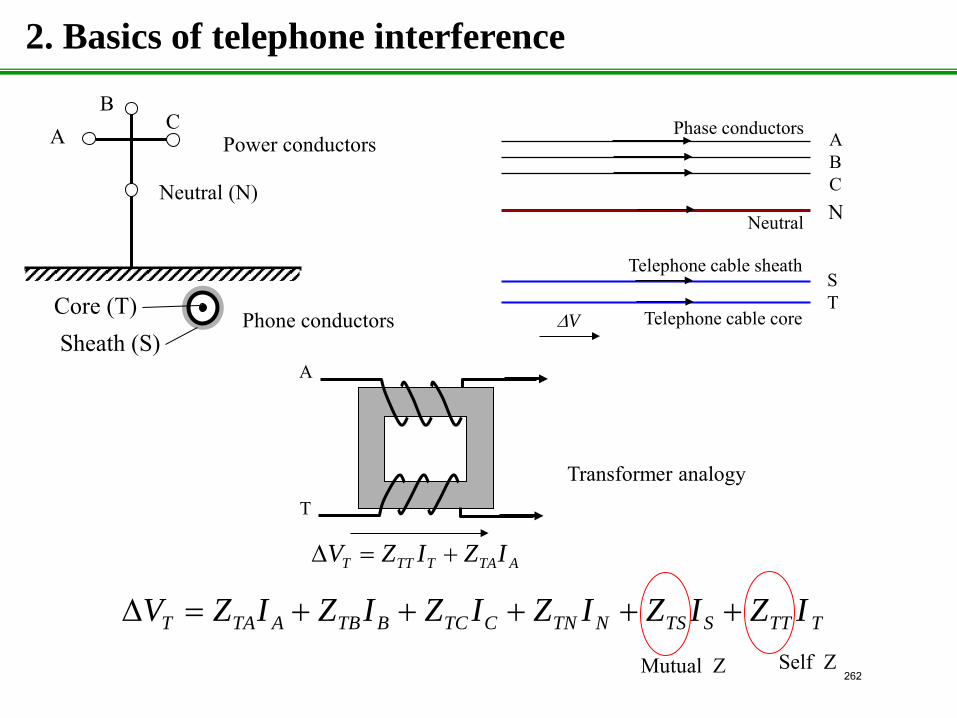
2. Basics of telephone interference
Power conductors
Sheath (S) Core (T) Phone conductors
Neutral (N)
A B
C A B C N
S T
Telephone cable core
Telephone cable sheath
Neutral
Phase conductors
∆V
ATATTTT IZIZV +=∆
A
T
Transformer analogy
TTTSTSNTNCTCBTBATAT IZIZIZIZIZIZV +++++=∆Self Z Mutual Z 262
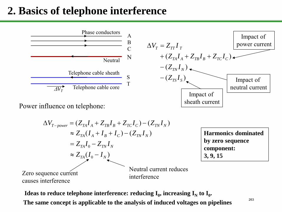
A B C N
S T Telephone cable core
Telephone cable sheath
Neutral
Phase conductors
∆VT
( )( )( )
T TT T
TA A TB B TC C
TN N
TS S
V Z IZ I Z I Z IZ IZ I
∆ =+ + +−−
Impact of power current
Impact of neutral current
Impact of sheath current
)()( NTNCTCBTBATApowerT IZIZIZIZV −++=∆ −
Power influence on telephone:
2. Basics of telephone interference
0
0
( ) ( )
( )
TA A B C TN N
TA TN N
TA N
Z I I I Z IZ I Z IZ I I
≈ + + −= −≈ −
Zero sequence current causes interference
Neutral current reduces interference
The same concept is applicable to the analysis of induced voltages on pipelines
Harmonics dominated by zero sequence component: 3, 9, 15
Ideas to reduce telephone interference: reducing I0, increasing IN to I0. 263
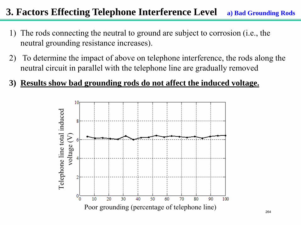
3. Factors Effecting Telephone Interference Level a) Bad Grounding Rods
1) The rods connecting the neutral to ground are subject to corrosion (i.e., the neutral grounding resistance increases).
2) To determine the impact of above on telephone interference, the rods along the neutral circuit in parallel with the telephone line are gradually removed
3) Results show bad grounding rods do not affect the induced voltage.
Tele
phon
e lin
e to
tal i
nduc
ed
volta
ge (V
)
Poor grounding (percentage of telephone line)264
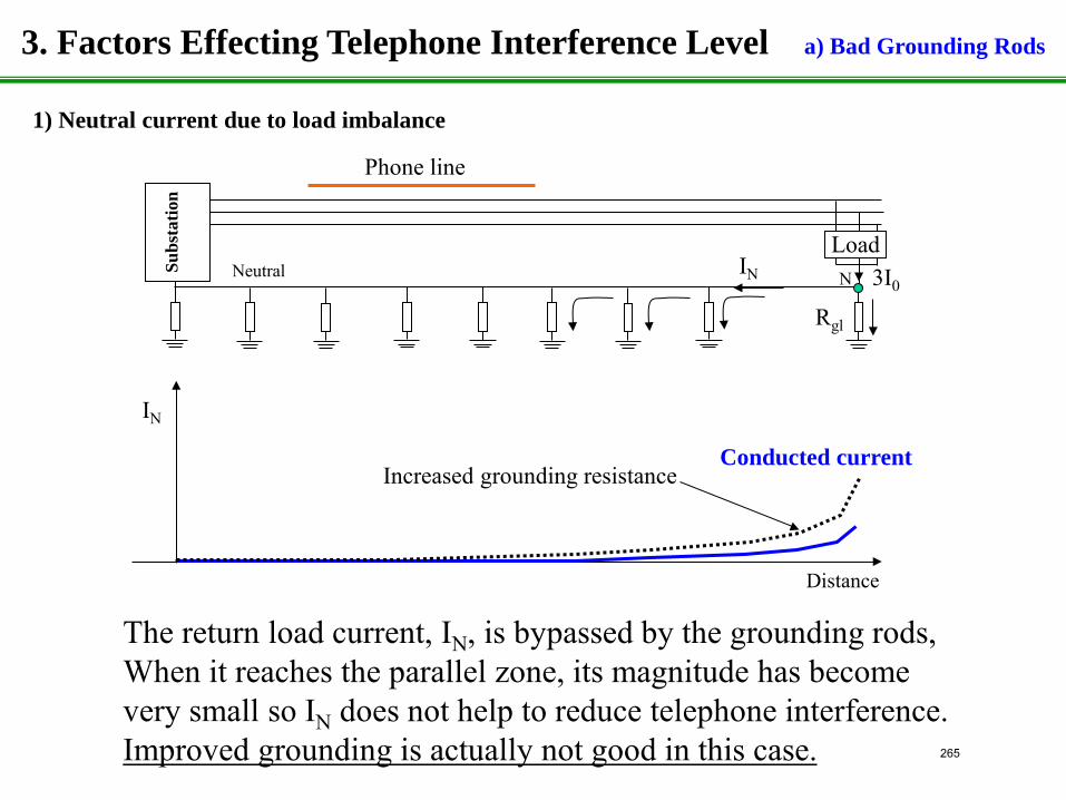
Phone line
The return load current, IN, is bypassed by the grounding rods, When it reaches the parallel zone, its magnitude has become very small so IN does not help to reduce telephone interference. Improved grounding is actually not good in this case.
Neutral Load
Su
bst
atio
n
3I0 IN
Rgl
N
1) Neutral current due to load imbalance
Increased grounding resistance
Distance
IN
Conducted current
3. Factors Effecting Telephone Interference Level a) Bad Grounding Rods
265
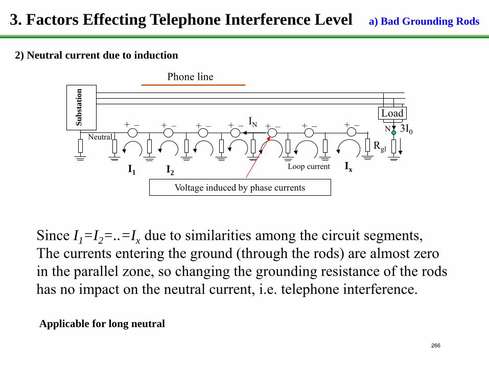
Neutral
Load
Su
bst
atio
n
3I0 IN
Rgl N + – + – + – + – + – + –
Loop current
Voltage induced by phase currents
Phone line
+ –
I1 I2
Since I1=I2=..=Ix due to similarities among the circuit segments, The currents entering the ground (through the rods) are almost zero in the parallel zone, so changing the grounding resistance of the rods has no impact on the neutral current, i.e. telephone interference.
Ix
2) Neutral current due to induction
3. Factors Effecting Telephone Interference Level a) Bad Grounding Rods
Applicable for long neutral
266
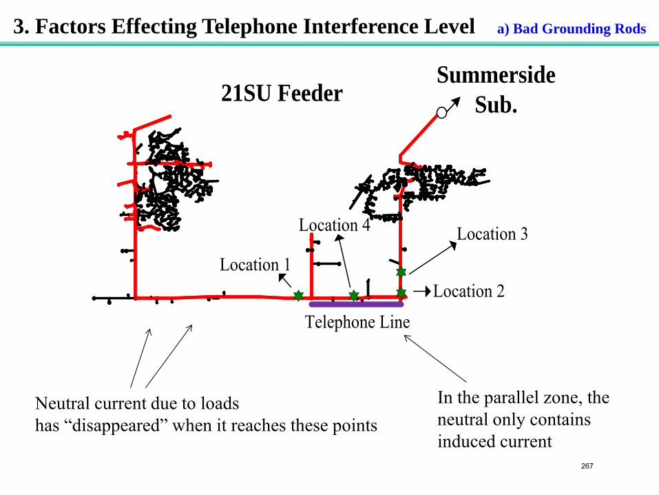
21SU Feeder
Telephone Line
Summerside Sub.
Location 3
Location 2
Location 4
Location 1
Neutral current due to loads has “disappeared” when it reaches these points
In the parallel zone, the neutral only contains induced current
3. Factors Effecting Telephone Interference Level a) Bad Grounding Rods
267
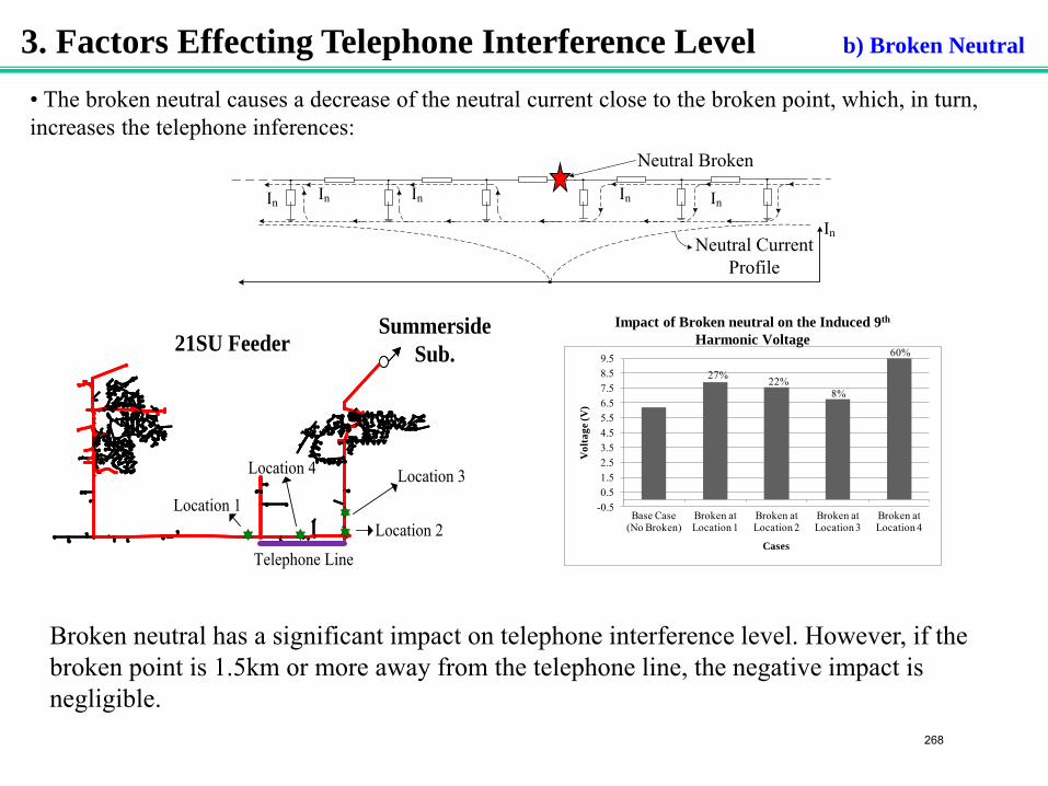
3. Factors Effecting Telephone Interference Level b) Broken Neutral
-0.50.51.52.53.54.55.56.57.58.59.5
Base Case (No Broken)
Broken at Location 1
Broken at Location 2
Broken at Location 3
Broken at Location 4
Vol
tage
(V)
Cases
27% 22%8%
60%
Impact of Broken neutral on the Induced 9th Harmonic Voltage 21SU Feeder
Telephone Line
Summerside Sub.
Location 3
Location 2
Location 4
Location 1
• The broken neutral causes a decrease of the neutral current close to the broken point, which, in turn, increases the telephone inferences:
Broken neutral has a significant impact on telephone interference level. However, if the broken point is 1.5km or more away from the telephone line, the negative impact is negligible.
Neutral Broken
InInInInIn
Neutral Current Profile
In
268
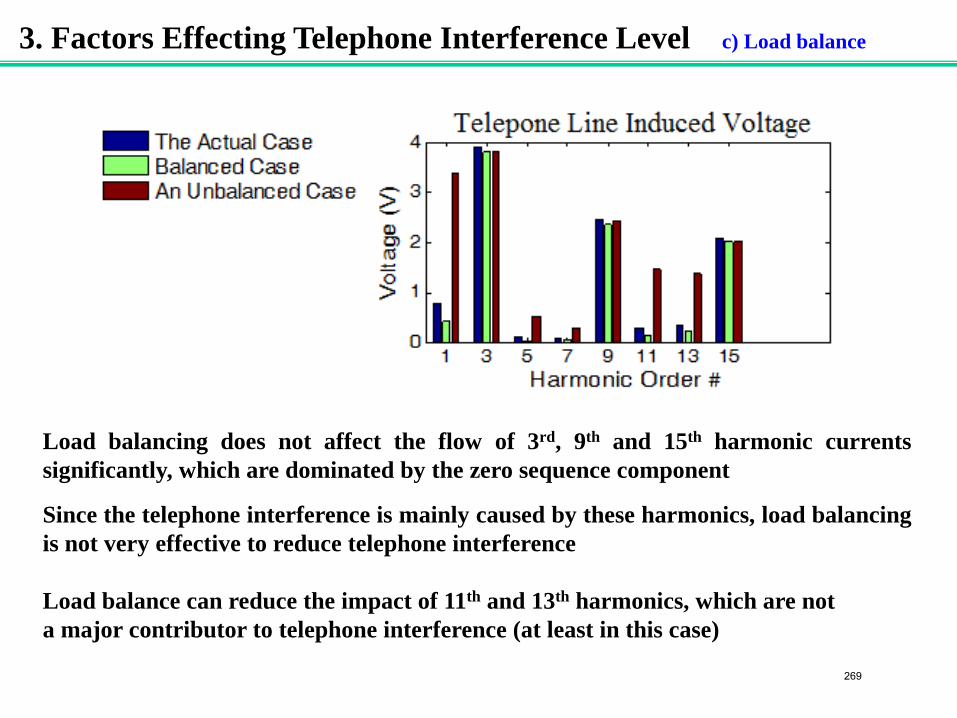
Load balancing does not affect the flow of 3rd, 9th and 15th harmonic currents significantly, which are dominated by the zero sequence component
Since the telephone interference is mainly caused by these harmonics, load balancing is not very effective to reduce telephone interference Load balance can reduce the impact of 11th and 13th harmonics, which are not a major contributor to telephone interference (at least in this case)
3. Factors Effecting Telephone Interference Level c) Load balance
269
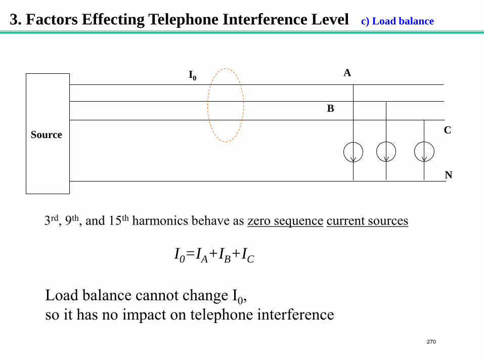
3. Factors Effecting Telephone Interference Level c) Load balance
Source
A
B
C
N
I0=IA+IB+IC
I0
Load balance cannot change I0, so it has no impact on telephone interference
3rd, 9th, and 15th harmonics behave as zero sequence current sources
270
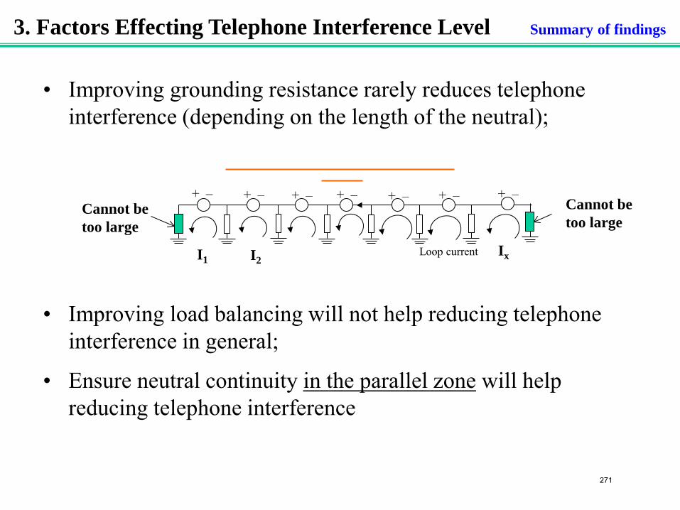
• Improving grounding resistance rarely reduces telephone interference (depending on the length of the neutral);
• Improving load balancing will not help reducing telephone interference in general;
• Ensure neutral continuity in the parallel zone will help reducing telephone interference
3. Factors Effecting Telephone Interference Level Summary of findings
+ – + – + – + – + – + –
Loop current
+ –
I1 I2 Ix
Cannot be too large
Cannot be too large
271
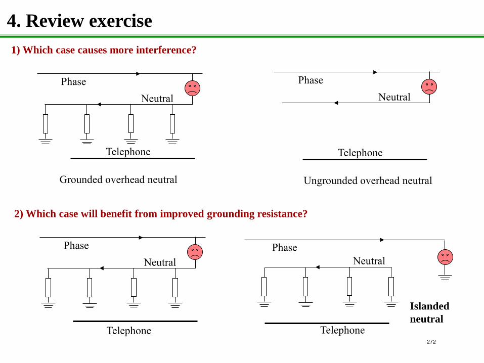
4. Review exercise
Phase Neutral
1) Which case causes more interference?
Phase Neutral
Grounded overhead neutral Ungrounded overhead neutral
Telephone Telephone
Neutral Phase
Neutral
Telephone Telephone
Phase
2) Which case will benefit from improved grounding resistance?
Islanded neutral
272
Alberta Power Industry Consortium
Grounding Issues 2009-2010
Project #1.1
Draft Report
Substation GPR Transfer to Feeder Neutral Points
Project Leader
Wilsun Xu
Project Team Members
Khaled Alawasa Janak Acharya
Department of Electrical & Computer Engineering University of Alberta
Edmonton, AB, T6G 2V4
Phone: 780-492-5965 [email protected]
November, 2009
273
1
NOTICE This report was prepared by the University of Alberta for the ultimate benefit of the Alberta Power Industry Consortium members (hereinafter called “SPONSORS”), who do not necessarily agree with the opinions expressed herein. Neither the SPONSORS, the University of Alberta, nor any other person acting on their behalf makes any warranty, expressed or implied, or assumes any legal responsibility for the accuracy of any information or for the completeness or usefulness of any apparatus, product or process disclosed, or accept liability for the use, or damages resulting from the use, thereof. Neither do they represent that their use would not infringe upon privately owned rights. Furthermore, the SPONSORS and the University of Alberta HEREBY DISCLAIM ANY AND ALL WARRANTIES, EXPRESSED OR IMPLIED, INCLUDING THE WARRANTIES OF MERCHANTABILITY AND FITNESS FOR A PARTICULAR PURPOSE, WHETHER ARISING BY LAW, CUSTOM, OR CONDUCT, WITH RESPECT TO ANY OF THE INFORMATION CONTAINED IN THIS REPORT. In no event shall the SPONSORS and the University of Alberta be liable for incidental or consequential damages because of use or any information contained in this report. Any reference in this report to any specific commercial product, process or service by tradename, trademark, manufacturer or otherwise does not necessarily constitute or imply its endorsement or recommendation by the University of Alberta or the SPONSORS.
274
i
Table of Contents
1. Introduction ................................................................................................................... 2
2. System Configurations and Parameters ................................................................... 2
3. Analytical Study............................................................................................................ 3
3.1 Substation GPR ........................................................................................................... 3
3.2 Neutral potential rise due to substation GPR ....................................................... 5
3.3 NPR transfer to customer .......................................................................................... 7
3.4 Representative values ................................................................................................ 8
3.5 Summary..................................................................................................................... 10
4. Case Study Results ..................................................................................................... 10
4.1 Effect of neutral grounding resistances ................................................................ 10
4.2 Effect of neutral grounding interval ..................................................................... 11
4.3 Effect of neutral length ............................................................................................ 12
4.5 Effect of customer grounding resistance .............................................................. 12
5. Summery and Conclusions ....................................................................................... 14
Appendix A: MGN configurations .................................................................................. 15
Appendix B : Equivalent impedance of MGN .............................................................. 15
275
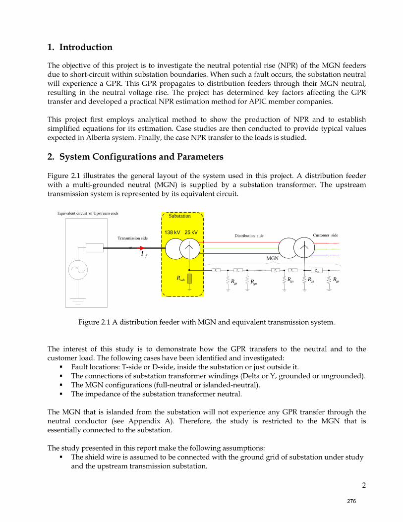
2
1. Introduction
The objective of this project is to investigate the neutral potential rise (NPR) of the MGN feeders due to short-circuit within substation boundaries. When such a fault occurs, the substation neutral will experience a GPR. This GPR propagates to distribution feeders through their MGN neutral, resulting in the neutral voltage rise. The project has determined key factors affecting the GPR transfer and developed a practical NPR estimation method for APIC member companies. This project first employs analytical method to show the production of NPR and to establish simplified equations for its estimation. Case studies are then conducted to provide typical values expected in Alberta system. Finally, the case NPR transfer to the loads is studied. 2. System Configurations and Parameters Figure 2.1 illustrates the general layout of the system used in this project. A distribution feeder with a multi-grounded neutral (MGN) is supplied by a substation transformer. The upstream transmission system is represented by its equivalent circuit.
138 kV
Substation
MGN
25 kV Transmission side Distribution side Customer side
gnR
nZnZnZnZnZ
subRgnR gnRgnRgnR
///
Equivalent circuit of Upstream ends
fI
Figure 2.1 A distribution feeder with MGN and equivalent transmission system.
The interest of this study is to demonstrate how the GPR transfers to the neutral and to the customer load. The following cases have been identified and investigated:
Fault locations: T-side or D-side, inside the substation or just outside it. The connections of substation transformer windings (Delta or Y, grounded or ungrounded). The MGN configurations (full-neutral or islanded-neutral). The impedance of the substation transformer neutral.
The MGN that is islanded from the substation will not experience any GPR transfer through the neutral conductor (see Appendix A). Therefore, the study is restricted to the MGN that is essentially connected to the substation. The study presented in this report make the following assumptions:
The shield wire is assumed to be connected with the ground grid of substation under study and the upstream transmission substation.
276
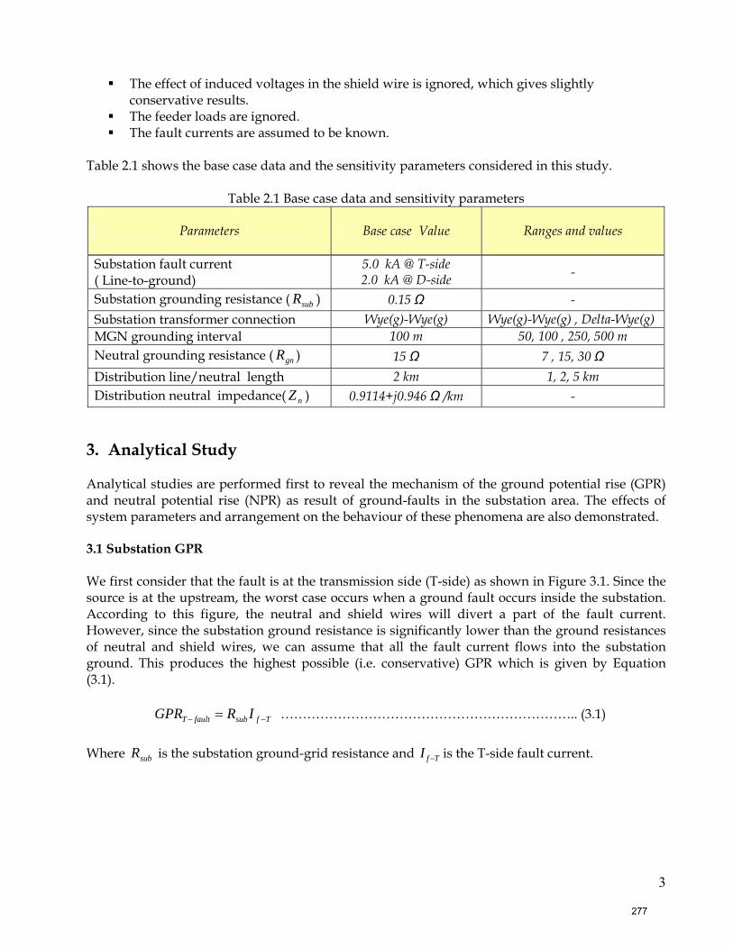
3
The effect of induced voltages in the shield wire is ignored, which gives slightly conservative results.
The feeder loads are ignored. The fault currents are assumed to be known.
Table 2.1 shows the base case data and the sensitivity parameters considered in this study.
Table 2.1 Base case data and sensitivity parameters
Parameters Base case Value
Ranges and values
Substation fault current ( Line-to-ground)
5.0 kA @ T-side 2.0 kA @ D-side -
Substation grounding resistance ( subR ) 0.15 Ω - Substation transformer connection Wye(g)-Wye(g) Wye(g)-Wye(g) , Delta-Wye(g) MGN grounding interval 100 m 50, 100 , 250, 500 m Neutral grounding resistance ( gnR ) 15 Ω 7 , 15, 30 Ω Distribution line/neutral length 2 km 1, 2, 5 km Distribution neutral impedance( nZ ) 0.9114+j0.946 Ω /km -
3. Analytical Study Analytical studies are performed first to reveal the mechanism of the ground potential rise (GPR) and neutral potential rise (NPR) as result of ground-faults in the substation area. The effects of system parameters and arrangement on the behaviour of these phenomena are also demonstrated. 3.1 Substation GPR We first consider that the fault is at the transmission side (T-side) as shown in Figure 3.1. Since the source is at the upstream, the worst case occurs when a ground fault occurs inside the substation. According to this figure, the neutral and shield wires will divert a part of the fault current. However, since the substation ground resistance is significantly lower than the ground resistances of neutral and shield wires, we can assume that all the fault current flows into the substation ground. This produces the highest possible (i.e. conservative) GPR which is given by Equation (3.1).
TfsubfaultT IRGPR −− = ………………………………………………………….. (3.1) Where subR is the substation ground-grid resistance and TfI − is the T-side fault current.
277
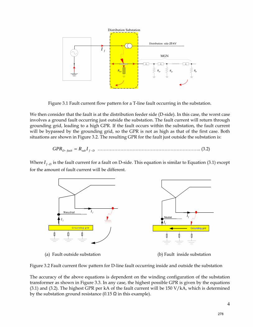
4
subR
Distribution Substation
MGN
Distribution side-25 kV
gnRgnRgnR
fI
nZ nZ nZ
Figure 3.1 Fault current flow pattern for a T-line fault occurring in the substation. We then consider that the fault is at the distribution feeder side (D-side). In this case, the worst case involves a ground fault occurring just outside the substation. The fault current will return through grounding grid, leading to a high GPR. If the fault occurs within the substation, the fault current will be bypassed by the grounding grid, so the GPR is not as high as that of the first case. Both situations are shown in Figure 3.2. The resulting GPR for the fault just outside the substation is:
DfsubfaultD IRGPR −− = ………………………………………………………….. (3.2)
Where DfI − is the fault current for a fault on D-side. This equation is similar to Equation (3.1) except for the amount of fault current will be different.
(a) Fault outside substation (b) Fault inside substation Figure 3.2 Fault current flow pattern for D-line fault occurring inside and outside the substation The accuracy of the above equations is dependent on the winding configuration of the substation transformer as shown in Figure 3.3. In any case, the highest possible GPR is given by the equations (3.1) and (3.2). The highest GPR per kA of the fault current will be 150 V/kA, which is determined by the substation ground resistance (0.15 Ω in this example).
N eutra l
G round ing g rid
fI
fI
Neutral
Grounding grid
fI
fI
278
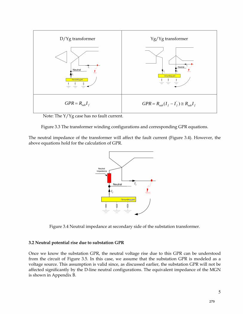
5
D/Yg transformer
Neutral
fI
Grounding grid
fI
Yg/Yg transformer
fI
Neutral
'fI
Grounding grid
fI
fsubIRGPR =
fsubffsub IRIIRGPR ≅−= )( '
Note: The Y/Yg case has no fault current.
Figure 3.3 The transformer winding configurations and corresponding GPR equations.
The neutral impedance of the transformer will affect the fault current (Figure 3.4). However, the above equations hold for the calculation of GPR.
Neutral
fI
fI
Neutral impedance
Grounding grid
Figure 3.4 Neutral impedance at secondary side of the substation transformer. 3.2 Neutral potential rise due to substation GPR Once we know the substation GPR, the neutral voltage rise due to this GPR can be understood from the circuit of Figure 3.5. In this case, we assume that the substation GPR is modeled as a voltage source. This assumption is valid since, as discussed earlier, the substation GPR will not be affected significantly by the D-line neutral configurations. The equivalent impedance of the MGN is shown in Appendix B.
279
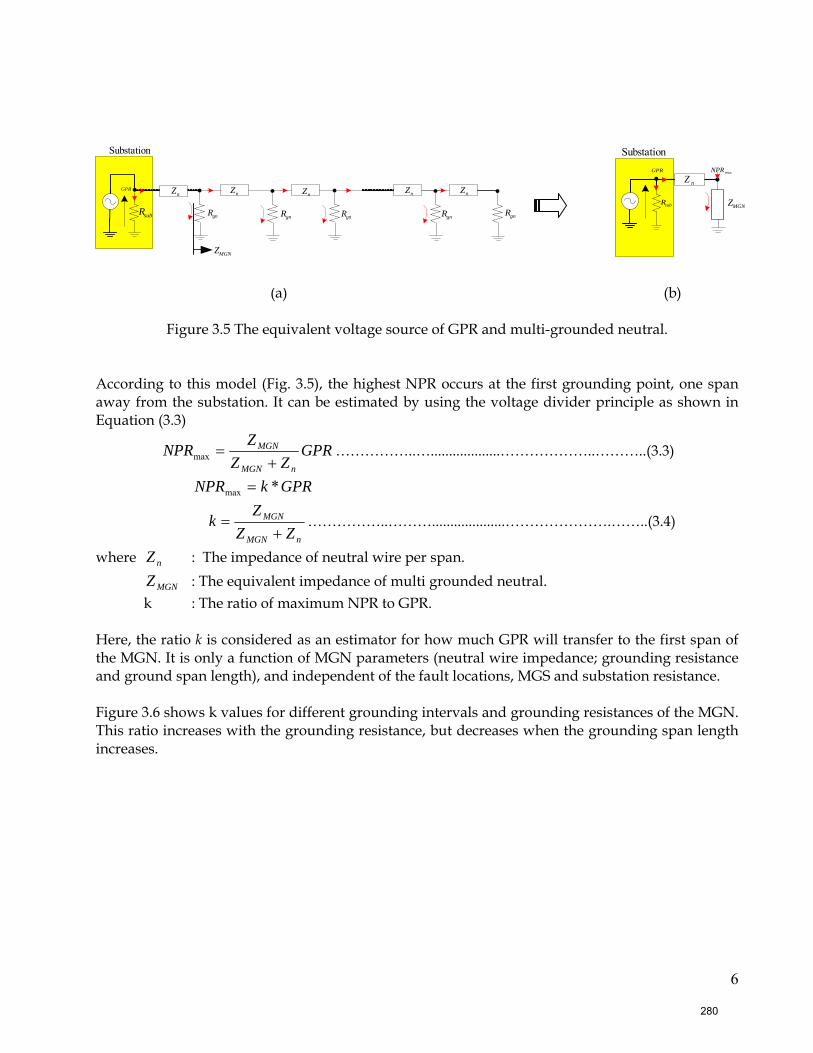
6
(a) (b)
Figure 3.5 The equivalent voltage source of GPR and multi-grounded neutral. According to this model (Fig. 3.5), the highest NPR occurs at the first grounding point, one span away from the substation. It can be estimated by using the voltage divider principle as shown in Equation (3.3)
GPRZZ
ZNPR
nMGN
MGN
+=max ……………..…...................………………..………..(3.3)
GPRkNPR *max =
nMGN
MGN
ZZ
Zk
+= ……………..………....................………………….……..(3.4)
where nZ : The impedance of neutral wire per span.
MGNZ : The equivalent impedance of multi grounded neutral. k : The ratio of maximum NPR to GPR.
Here, the ratio k is considered as an estimator for how much GPR will transfer to the first span of the MGN. It is only a function of MGN parameters (neutral wire impedance; grounding resistance and ground span length), and independent of the fault locations, MGS and substation resistance.
Figure 3.6 shows k values for different grounding intervals and grounding resistances of the MGN. This ratio increases with the grounding resistance, but decreases when the grounding span length increases.
MGNZsubR
Substation
maxNPRGPR
nZ
gnRgnRgnRgnR
nZ nnZ
subR
Substation
nZnZ nZ nZGPR
MGNZ
gnR
280
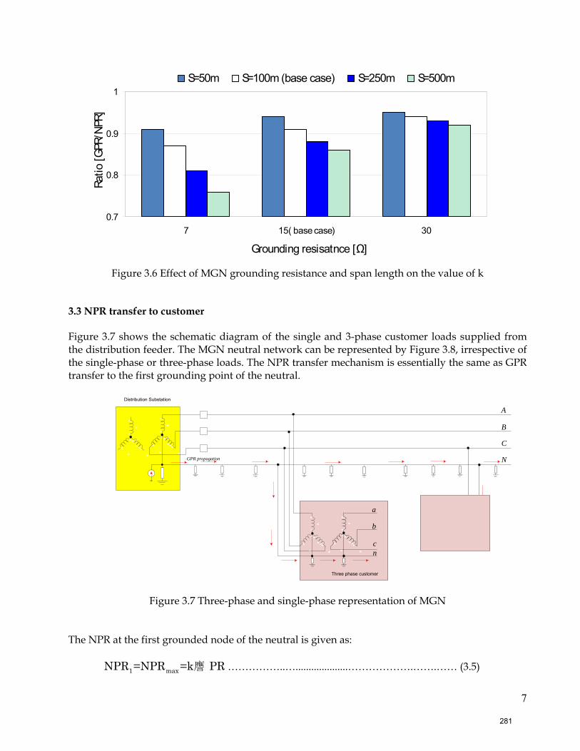
7
0.7
0.8
0.9
1
7 15( base case) 30
Grounding resisatnce [Ω]
Ratio
[GPR
/NPR
]
S=50m S=100m (base case) S=250m S=500m
Figure 3.6 Effect of MGN grounding resistance and span length on the value of k
3.3 NPR transfer to customer Figure 3.7 shows the schematic diagram of the single and 3-phase customer loads supplied from the distribution feeder. The MGN neutral network can be represented by Figure 3.8, irrespective of the single-phase or three-phase loads. The NPR transfer mechanism is essentially the same as GPR transfer to the first grounding point of the neutral.
A
B
C
N
Distribution Substation
GPR propagation
a
b
Three phase customer
cn
cn
Single phase customer
Figure 3.7 Three-phase and single-phase representation of MGN The NPR at the first grounded node of the neutral is given as:
1 maxNPR =NPR =k譍 PR ……………..…....................……………….…….…… (3.5)
281
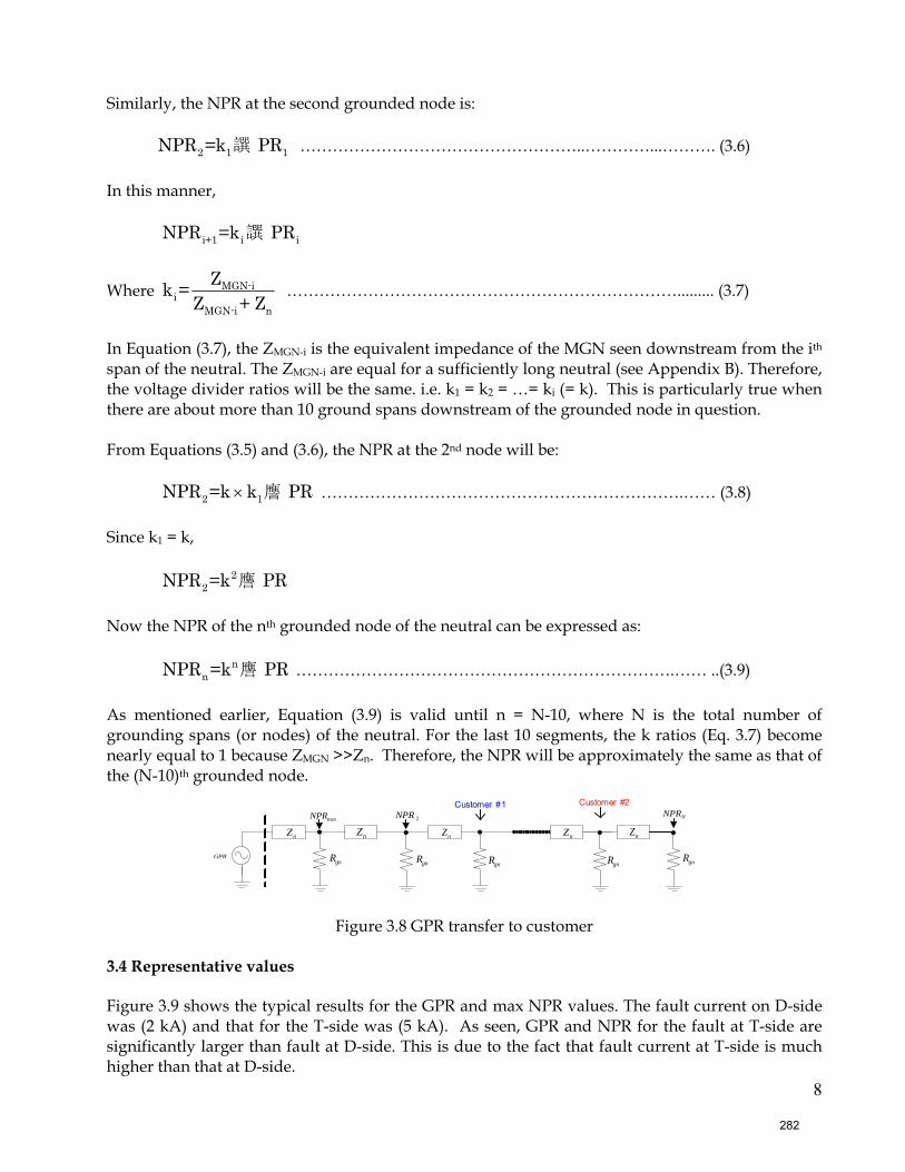
8
Similarly, the NPR at the second grounded node is: 2 1 1NPR =k 譔 PR ……………………………………………..…………...………. (3.6) In this manner,
i+1 i iNPR =k 譔 PR
Where MGN-ii
MGN-i n
Zk =Z + Z
………………………………………………………………......... (3.7)
In Equation (3.7), the ZMGN-i is the equivalent impedance of the MGN seen downstream from the ith span of the neutral. The ZMGN-i are equal for a sufficiently long neutral (see Appendix B). Therefore, the voltage divider ratios will be the same. i.e. k1 = k2 = …= ki (= k). This is particularly true when there are about more than 10 ground spans downstream of the grounded node in question. From Equations (3.5) and (3.6), the NPR at the 2nd node will be:
2 1NPR =k k 譍 PR× ………………………………………………………….…… (3.8)
Since k1 = k,
22NPR =k 譍 PR
Now the NPR of the nth grounded node of the neutral can be expressed as:
nnNPR =k 譍 PR …………………………………………………………….…… ..(3.9)
As mentioned earlier, Equation (3.9) is valid until n = N-10, where N is the total number of grounding spans (or nodes) of the neutral. For the last 10 segments, the k ratios (Eq. 3.7) become nearly equal to 1 because ZMGN >>Zn. Therefore, the NPR will be approximately the same as that of the (N-10)th grounded node.
gnRgnRgnRgnR
nZ nnZnZ nZ nZ nZ
maxNPR
GPRgnR
Customer #1 Customer #2
2NPR NNPR
Figure 3.8 GPR transfer to customer 3.4 Representative values Figure 3.9 shows the typical results for the GPR and max NPR values. The fault current on D-side was (2 kA) and that for the T-side was (5 kA). As seen, GPR and NPR for the fault at T-side are significantly larger than fault at D-side. This is due to the fact that fault current at T-side is much higher than that at D-side.
282
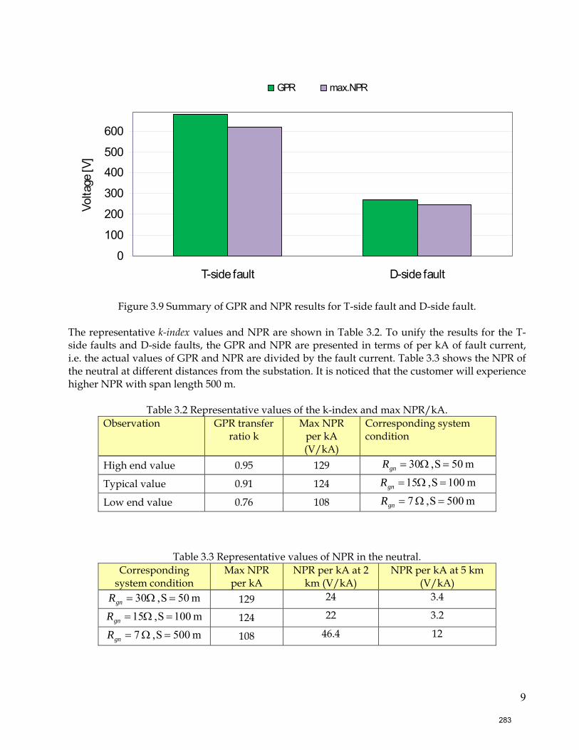
9
0
100
200
300
400
500
600
T-side fault D-side fault
Volta
ge [V
]GPR max.NPR
Figure 3.9 Summary of GPR and NPR results for T-side fault and D-side fault.
The representative k-index values and NPR are shown in Table 3.2. To unify the results for the T-side faults and D-side faults, the GPR and NPR are presented in terms of per kA of fault current, i.e. the actual values of GPR and NPR are divided by the fault current. Table 3.3 shows the NPR of the neutral at different distances from the substation. It is noticed that the customer will experience higher NPR with span length 500 m.
Table 3.2 Representative values of the k-index and max NPR/kA. Observation GPR transfer
ratio k Max NPR
per kA (V/kA)
Corresponding system condition
High end value 0.95 129 m 50S, 30 =Ω=gnR
Typical value 0.91 124 m 001S, 15 =Ω=gnR
Low end value 0.76 108 m 500S, 7 =Ω=gnR
Table 3.3 Representative values of NPR in the neutral. Corresponding
system condition Max NPR
per kA NPR per kA at 2
km (V/kA) NPR per kA at 5 km
(V/kA) m 50S, 30 =Ω=gnR 129 24 3.4
m 001S, 15 =Ω=gnR 124 22 3.2
m 500S, 7 =Ω=gnR 108 46.4 12
283
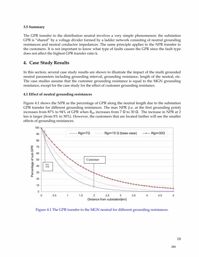
10
3.5 Summary The GPR transfer to the distribution neutral involves a very simple phenomenon: the substation GPR is “shared” by a voltage divider formed by a ladder network consisting of neutral grounding resistances and neutral conductor impedances. The same principle applies to the NPR transfer to the customers. It is not important to know what type of faults causes the GPR since the fault type does not affect the highest GPR transfer ratio k. 4. Case Study Results In this section, several case study results are shown to illustrate the impact of the multi grounded neutral parameters including grounding interval, grounding resistance, length of the neutral, etc. The case studies assume that the customer grounding resistance is equal to the MGN grounding resistance, except for the case study for the effect of customer grounding resistance. 4.1 Effect of neutral grounding resistances Figure 4.1 shows the NPR as the percentage of GPR along the neutral length due to the substation GPR transfer for different grounding resistances. The max NPR (i.e. at the first grounding point) increases from 87% to 94% of GPR when Rgn increases from 7 Ω to 30 Ω. The increase in NPR at 2 km is larger (from 8% to 30%). However, the customers that are located farther will see the smaller effects of grounding resistances.
0
10
20
30
40
50
60
70
80
90
100
0 0.5 1 1.5 2 2.5 3 3.5 4 4.5 5Distance from substation[km]
Per
cent
age
of s
ub.G
PR
Rgn=7Ω Rgn=15 Ω (base case) Rgn=30Ω
Figure 4.1 The GPR transfer to the MGN neutral for different grounding resistances.
Max. NPR
Customer
284
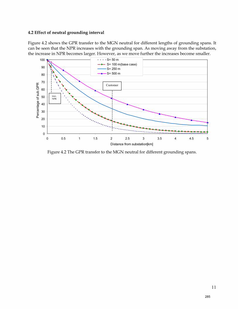
11
4.2 Effect of neutral grounding interval Figure 4.2 shows the GPR transfer to the MGN neutral for different lengths of grounding spans. It can be seen that the NPR increases with the grounding span. As moving away from the substation, the increase in NPR becomes larger. However, as we move further the increases become smaller.
0
10
20
30
40
50
60
70
80
90
100
0 0.5 1 1.5 2 2.5 3 3.5 4 4.5 5
Distance from substation[km]
Per
cent
age
of s
ub.G
PR
S= 50 mS= 100 m(base case)S= 250 mS= 500 m
Figure 4.2 The GPR transfer to the MGN neutral for different grounding spans.
Customer
max.NPR
285
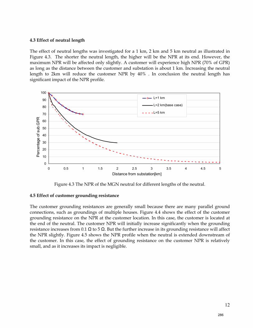
12
4.3 Effect of neutral length The effect of neutral lengths was investigated for a 1 km, 2 km and 5 km neutral as illustrated in Figure 4.3. The shorter the neutral length, the higher will be the NPR at its end. However, the maximum NPR will be affected only slightly. A customer will experience high NPR (70% of GPR) as long as the distance between the customer and substation is about 1 km. Increasing the neutral length to 2km will reduce the customer NPR by 40% . In conclusion the neutral length has significant impact of the NPR profile.
0
10
20
30
40
50
60
70
80
90
100
0 0.5 1 1.5 2 2.5 3 3.5 4 4.5 5
Distance from substation[km]
Per
cent
age
of s
ub.G
PR
L=1 km
L=2 km(base case)
L=5 km
Figure 4.3 The NPR of the MGN neutral for different lengths of the neutral.
4.5 Effect of customer grounding resistance The customer grounding resistances are generally small because there are many parallel ground connections, such as groundings of multiple houses. Figure 4.4 shows the effect of the customer grounding resistance on the NPR at the customer location. In this case, the customer is located at the end of the neutral. The customer NPR will initially increase significantly when the grounding resistance increases from 0.1 Ω to 5 Ω. But the further increase in its grounding resistance will affect the NPR slightly. Figure 4.5 shows the NPR profile when the neutral is extended downstream of the customer. In this case, the effect of grounding resistance on the customer NPR is relatively small, and as it increases its impact is negligible.
286
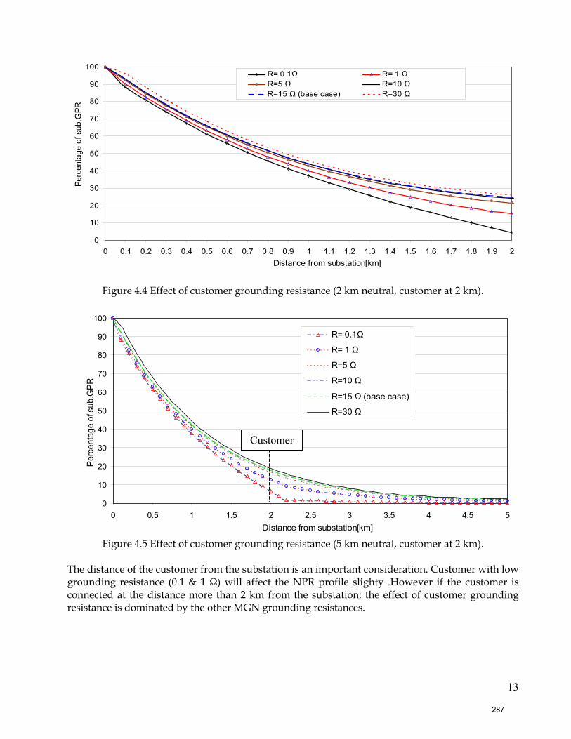
13
0
10
20
30
40
50
60
70
80
90
100
0 0.1 0.2 0.3 0.4 0.5 0.6 0.7 0.8 0.9 1 1.1 1.2 1.3 1.4 1.5 1.6 1.7 1.8 1.9 2Distance from substation[km]
Perc
enta
ge o
f sub
.GPR
R= 0.1Ω R= 1 Ω R=5 Ω R=10 Ω R=15 Ω (base case) R=30 Ω
Figure 4.4 Effect of customer grounding resistance (2 km neutral, customer at 2 km).
0
10
20
30
40
50
60
70
80
90
100
0 0.5 1 1.5 2 2.5 3 3.5 4 4.5 5Distance from substation[km]
Perc
enta
ge o
f sub
.GPR
R= 0.1Ω
R= 1 Ω
R=5 Ω
R=10 Ω
R=15 Ω (base case)
R=30 Ω
Figure 4.5 Effect of customer grounding resistance (5 km neutral, customer at 2 km).
The distance of the customer from the substation is an important consideration. Customer with low grounding resistance (0.1 & 1 Ω) will affect the NPR profile slighty .However if the customer is connected at the distance more than 2 km from the substation; the effect of customer grounding resistance is dominated by the other MGN grounding resistances.
Customer
287
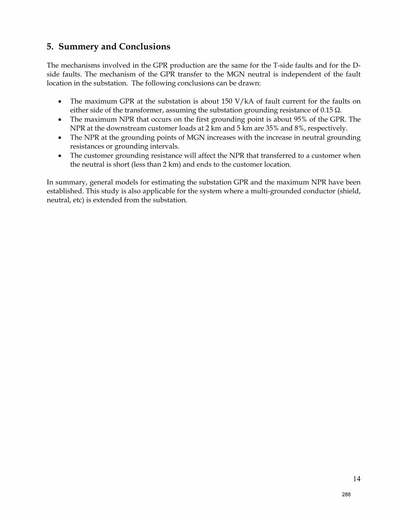
14
5. Summery and Conclusions The mechanisms involved in the GPR production are the same for the T-side faults and for the D-side faults. The mechanism of the GPR transfer to the MGN neutral is independent of the fault location in the substation. The following conclusions can be drawn:
• The maximum GPR at the substation is about 150 V/kA of fault current for the faults on either side of the transformer, assuming the substation grounding resistance of 0.15 Ω.
• The maximum NPR that occurs on the first grounding point is about 95% of the GPR. The NPR at the downstream customer loads at 2 km and 5 km are 35% and 8%, respectively.
• The NPR at the grounding points of MGN increases with the increase in neutral grounding resistances or grounding intervals.
• The customer grounding resistance will affect the NPR that transferred to a customer when the neutral is short (less than 2 km) and ends to the customer location.
In summary, general models for estimating the substation GPR and the maximum NPR have been established. This study is also applicable for the system where a multi-grounded conductor (shield, neutral, etc) is extended from the substation.
288
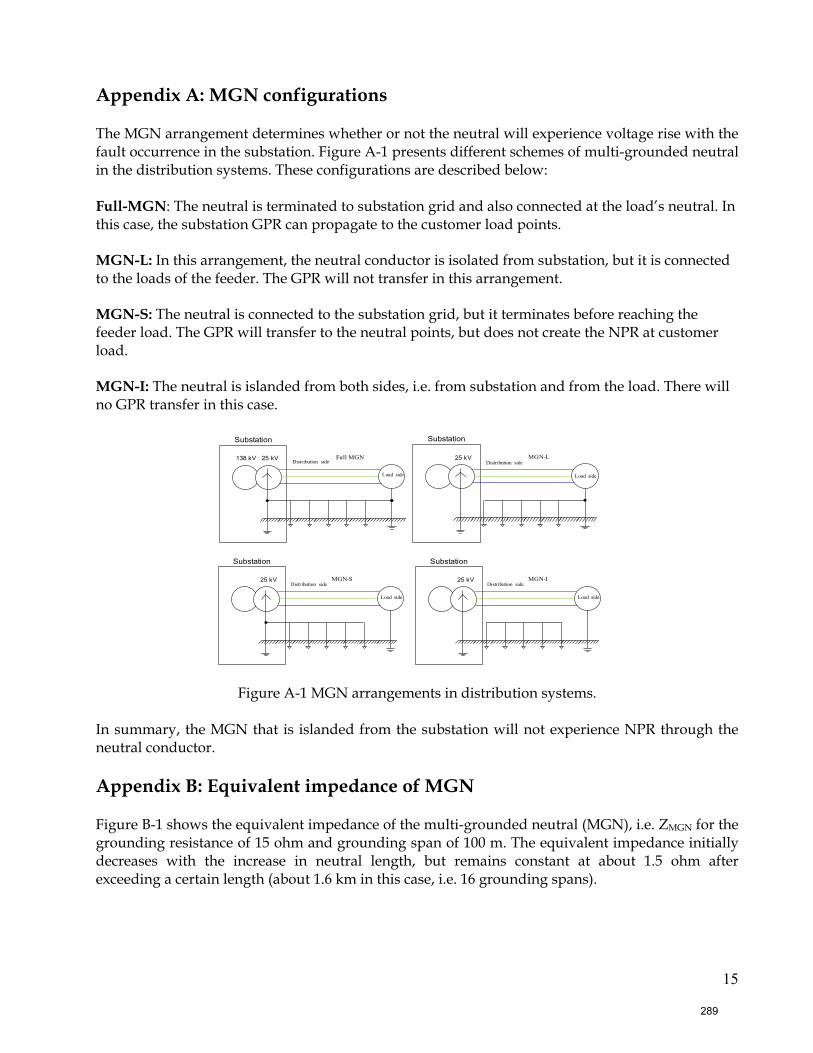
15
Appendix A: MGN configurations
The MGN arrangement determines whether or not the neutral will experience voltage rise with the fault occurrence in the substation. Figure A-1 presents different schemes of multi-grounded neutral in the distribution systems. These configurations are described below: Full-MGN: The neutral is terminated to substation grid and also connected at the load’s neutral. In this case, the substation GPR can propagate to the customer load points. MGN-L: In this arrangement, the neutral conductor is isolated from substation, but it is connected to the loads of the feeder. The GPR will not transfer in this arrangement. MGN-S: The neutral is connected to the substation grid, but it terminates before reaching the feeder load. The GPR will transfer to the neutral points, but does not create the NPR at customer load. MGN-I: The neutral is islanded from both sides, i.e. from substation and from the load. There will no GPR transfer in this case.
138 kV
Substation
Full MGN25 kV Distribution side
Substation
MGN-S25 kV Distribution side
Substation
MGN-I25 kV Distribution side
Substation
MGN-L25 kV Distribution side
Load sideLoad side
Load side Load side
Figure A-1 MGN arrangements in distribution systems.
In summary, the MGN that is islanded from the substation will not experience NPR through the neutral conductor. Appendix B: Equivalent impedance of MGN Figure B-1 shows the equivalent impedance of the multi-grounded neutral (MGN), i.e. ZMGN for the grounding resistance of 15 ohm and grounding span of 100 m. The equivalent impedance initially decreases with the increase in neutral length, but remains constant at about 1.5 ohm after exceeding a certain length (about 1.6 km in this case, i.e. 16 grounding spans).
289
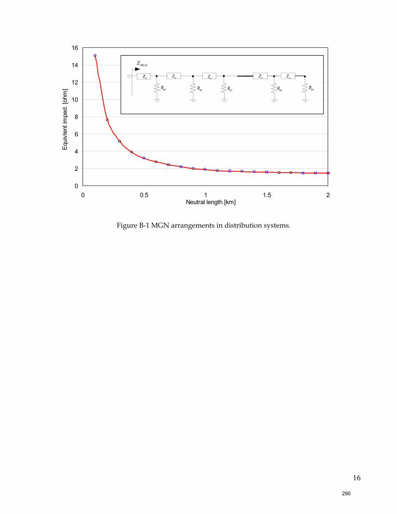
16
0
2
4
6
8
10
12
14
16
0 0.5 1 1.5 2Neutral length [km]
Equi
vlen
t im
ped.
[ohm
]
Figure B-1 MGN arrangements in distribution systems.
gnRgnRgnRgnR
nZ nnZnZ nZ nZ nZ
gnR
MGNZ
290