Embed Size (px)
Citation preview

Precision resonance tuning and design of SiNphotonic crystal reflectorsSIMON BERNARD,1 CHRISTOPH REINHARDT,1 VINCENT DUMONT,1 YVES-ALAIN PETER,2 AND JACK C. SANKEY1,*1Department of Physics, McGill University, Montréal, Québec H3A 2T8, Canada2Department of Engineering Physics, Polytechnique, Montréal, Québec H3C 3A7, Canada*Corresponding author: [email protected]
Received 11 October 2016; revised 7 November 2016; accepted 7 November 2016; posted 8 November 2016 (Doc. ID 278301);published 2 December 2016
Photonic crystal reflector (PCR) membranes exhibit aresonantly enhanced normal-incidence reflectivity. Manyapplications require this resonance to occur at a specificwavelength, however, imposing geometrical tolerances thatare not reliably achieved with standard nanolithography.Here we finely tune the resonant wavelength of a free-standing Si3N4 PCR membrane with iterative hydrofluoricacid etches, achieving a 57 nm thin crystal with a resonantwavelength 0.15 nm (0.04 linewidths) away from our target(1550 nm). This thin crystal exhibits a broader, shallowertransmission dip than its simulated response to planewaves, and we identify two causes related to beam collima-tion. Finally, we present a series of simulations and generaldesign considerations for realizing robust, high-reflectivityresonances. © 2016 Optical Society of America
OCIS codes: (230.5298) Photonic crystals; (220.4241) Nanostructure
fabrication; (230.4040) Mirrors; (220.4880) Optomechanics.
https://doi.org/10.1364/OL.41.005624
Planar photonic crystals provide a powerful means of control-ling the flow of light [1] and can be engineered to stronglyinteract with waves propagating out of the crystal plane [2].Among other things, this enables compact etalon filters[3,4], high-performance surface-emitting lasers [5,6], electro-mechanically [7] or optomechanically [8] actuated laser mir-rors, nonlinear optical elements [9], and biochemical sensors[10,11]. Freestanding 2D photonic crystal reflectors (PCRs)[12,13], in particular, represent an advantageous technologyin the field of optomechanics [14], wherein it is desirable tocreate a lightweight mass that strongly reflects incident light,maximizing the influence of each photon. With this aim, sin-gle-layer reflectors have been fabricated from InP [8,15–17]and SiN [18–22]. High-stress Si3N4 is of particular interest,since it combines the ease of fabrication, low optical loss[23,24], and the lowest mechanical dissipation and force noise[21,25].
An outstanding goal is to reliably fabricate PCRs havinghigh reflectivity at a pre-specified wavelength, to match (for ex-ample) that of a low-noise laser, an atomic transition, or another
reflector. It is straightforward to change the response of the pho-tonic crystals via geometry [26,27], but the high-reflectivitywavelength range achieved by 2D SiN PCRs is a quantity typ-ically measured in nanometers, imposing geometrical tolerancesthat are not reliably achieved with standard lithography.However, crystals made from other materials can be finely tunedafter fabrication, e.g., by wet etching [28–30] or atomic layerdeposition [31,32]. Combining these ideas with a techniquefor tuning SiN microdisks [33], we achieve the desired precisionfor a thin, freestanding PCR using iterative hydrofluoric (HF)acid dips. Specifically, we systematically tune the resonant wave-length of a ∼60 nm thin photonic crystal by 16 nm, such that itfinally resides within 0.15 nm (0.04 linewidths) of our targetedwavelength λ0 � 1550 nm. This is achieved with a 2D squarelattice of holes, but should be readily applicable to 1D gratings[19,20] and other SiN structures.
A second question is whether there exists a fundamentaland/or practical limitation on how thin these structures canbe made while still maintaining high reflectivity. Despite thecomparatively low feature roughness, our thin structures exhibita transmission resonance that is broader and shallower than itssimulated response to incident plane waves. This broadening hasbeen observed in similar crystals of thickness at or below 100 nm[18,21] and attributed to disorder not included in periodic crys-tal simulations [18]. Since then, however, thicker PCRs havingcomparable disorder achieved a transmission dip well below 1%[21,22]. Building on previous investigations of angular- andcollimation-induced changes in the transmission spectrum ofoptically thick structures [34], we present simulations illustratingtwo effects leading to collimation-induced resonance broaden-ing: (1) the previously identified angular dependence of the “pri-mary” resonance wavelength [13,34], and (2) “parasitic” crystalmodes that couple only to off-normal plane waves [13,18,22,34]and strongly interfere with the primary resonance. We also iden-tify and calculate figures of merit for crystals of varied geometry,providing a basic guide for reliably minimizing (or balancing)these effects.
Our primary goal is to tune the resonance of a thin Si3N4
PCR to a convenient (telecom) laser wavelength λ0 �1550 nm by first fabricating a crystal with too much material,and then iteratively measuring the transmission spectrum T
5624 Vol. 41, No. 24 / December 15 2016 / Optics Letters Letter
0146-9592/16/245624-04 Journal © 2016 Optical Society of America

and etching with HF until the resonant wavelength λr (definedhere to be at the minimal value of T ) is close to λ0. The crystalis initially fabricated from a Si wafer coated with 100 nm thickstoichiometric Si3N4. We open a square window in the back-side nitride with optical lithography and reactive ion etching(RIE), then etch the exposed silicon in a 45% KOH solutionat 75°C (∼35 μm∕hr etch rate) to release the front membrane.This is coated with a 150 nm resist (Zeon ZEP520A:anisole,1∶2 ratio, spun at 3000 rpm, oven-baked 40 min at 180°C),and exposed in an electron-beam writer (50 μC∕cm2, 10 kV)to define the crystal mask. The resist is developed for 60 s(Zeon ZED-N50), and rinsed 15 s in isopropyl alcohol.The pattern is transferred to the membrane via RIE withCHF3 (30 sccm), CF4 (70 sccm), and Ar (7 sccm) at30 mTorr and 100 W. The resist is stripped withMicroposit Remover 1165 (30 min, 60°C) followed by piranha(3∶1 H2SO4:H2O2, 15 min). Finally, the sample is furthercleaned and thinned for 10 min in 10∶1 HF at 26°C (notewe often do not fully etch the nitride during RIE to reducebreakage); then it is rinsed with water and methanol. The struc-ture has nominal thickness h � 66� 1 nm (measured) andholes of diameter d � 614 nm (edge roughness ∼15 nm),in a square lattice spaced by a � 1500� 6 nm [Fig. 1(a)].
We locate the crystal resonance with a swept-wavelength (λ)transmission measurement [Fig. 1(b)]. Light from a tunablediode laser is focused to a Gaussian spot having a 1∕e2 intensitydiameter D � 60� 1 μm at the crystal [spot size drawn inFig. 1(a)], and the transmitted light is collected by a photodiode(PD). Fluctuations in the incident power are monitored bya second “reference” PD. A half-wave plate (HWP) andlinear polarizer (LP) fix the input polarization to avoid any
polarization dependence of the beam splitter (BS) and otheroptics; the PCR response is found to be polarization indepen-dent. Figure 1(c) shows T �λ� for the crystal (i) as fabricated andafter (ii) 130 s, (iii) 165 s, and (iv) 195 s in HF (total) at 26°C.Immersing the structure in HF decreases h (at a rate∼3 nm∕min ) and increases d (∼1 nm∕min ), displacingthe resonance toward shorter wavelength. Using this technique,the resonance is tuned to within 0.15 nm of λ0 (red curve). Thetuning rate of λr is found to fluctuate [−4.4 nm∕min (i → ii),−3.2 nm∕min (ii → iii), and −7.9 nm∕min (iii → iv)],which can be mitigated with a slower, buffered solution, fluidflow, and smaller steps, as necessary.
The gray curves in Fig. 1(c) show the simulated response ofan infinite crystal (i.e., a single unit cell with periodic boundaryconditions in MEEP [35]) to normal-incidence plane waves.The hole diameters d (which have a comparatively weak effecton λr ) are (i) 614 nm and (iv) 618 nm, matching the valuesfrom the SEM images, e.g., the inset of Fig. 1(a), and the thick-nesses h are set to (i) 62.5 nm and (iv) 54.5 nm to match theobserved λr . These h values are within 6% of the those directlymeasured by a reflectometer, and the h change of 8 nm is con-sistent with the measured change of 9� 1 nm, lending cred-ibility to the simulation. The linewidth of the measuredresonance is also reduced by 20% as the device is thinned,qualitatively consistent with a 30% decrease predicted bythe simulations, though the measured resonance is also a factorof 1.6 broader than simulations suggest. Moreover, the trans-mission reaches a minimum value T min between 0.32(h � 66 nm) and 0.38 (h � 57 nm), placing upper boundsof 0.68 and 0.62 on the reflectivity.
We now consider a practical performance limitation arisingfrom the sensitivity of T to incidence angle θ [13,34]. Sincecollimated beams are composed of a weighted superpositionof plane waves from all θ [spanning θD ∼ 1° for our 60 μmspot; see the inset of Fig. 1(c)], the resonance can be averagedaway. One can compensate for this by increasing D to reduceθD, but this requires a larger-area crystal, which is disadvanta-geous for most applications, and furthermore difficult tofabricate. The crystal in Fig. 1, for example, uses the fullhigh-resolution electron beam write field. Using a larger fieldreduces precision, and using multiple fields adds detrimentaldislocations between adjacent fields.
To get a sense of when beam divergence is important,Fig. 2(a) shows illustrative simulations for Si3N4 crystals of var-ied geometry and incidence angles. The transverse-electric (TE)polarization (inset) is chosen in (a)–(c) to maximize the effect ofθ on T ; for the transverse-magnetic (TM) polarization [see(d)], T is comparatively unaffected. The 200 nm thick crystalin (a) exhibits a single, broad “primary” resonance near1550 nm for θ � 0 (blue curve) and, as θ is increased, a second“parasitic” resonance emerges. These additional resonances areunderstood well, and their symmetry precludes coupling tonormal-incidence waves [12,18,22,34]. Here the parasitic res-onance has a modest impact for θ ≠ 0, shifting λr slightly.Figure 2(b) shows the same simulations for a 100 nm thickcrystal. In this case, the separation Δ between the primaryand parasitic resonances is only a few nanometers, and the effectis profound: one would not expect a high reflectivity for a rea-sonably collimated beam. Figure 2(c) illustrates another causeof collimation broadening [34] that can occur in geometrieswhere Δ is large: λr in general, varies as θ2 to leading order.
Fig. 1. Etch-tuned PCR. (a) Si3N4 PCR with thicknessh � 66� 1 nm, hole diameter d � 614 nm (�7 nm hole-to-holewith edge roughness∼15 nm), and lattice constant a � 1500� 6 nm.The red spot indicates 1∕e2 diameter D � 60� 1 μm of the laser.(b) Measuring T : laser passes through a HWP, LP, BS, lens, and crystal,and is measured by a PD. The power is monitored with a “reference”PD. (c) T �λ� for the crystal as fabricated (i) and then iteratively im-mersed in HF for (ii) 130 s, (iii) 165 s and (iv) 195 s (total), reducingh by 9� 1 nm and increasing d by ∼4 nm. The gray curves show thesimulated response to normal-incidence plane waves, assuming refrac-tive index 2, hole diameters (i) 614 nm and (iv) 618 nm, and thicknesses(i) 62.5 nm and (iv) 54.5 nm.
Letter Vol. 41, No. 24 / December 15 2016 / Optics Letters 5625

The geometry of Fig. 2(c) is close to that of our devicesin Fig. 1, suggesting this is the dominant mechanism.Broadening has been observed for similarly thin Si3N4 crystals[18,21], and the resonance was found to split, broaden, andshallow when changing the beam’s incident angle [18].
For a given crystal thickness h, the desired resonance can beachieved over a wide range of lattice constants a and hole diam-eters d , as shown in Fig. 3(a), enabling some minimization ofthese effects. Figure 3(b) shows the detuning Δ of the nearestparasitic resonance, which can be made largest in the thickestdevices (near a � 0.78λ0). The angular sensitivity ∂2θλr in (c)tends toward lower values for thicker devices, and is stronglyinfluenced by parasitic modes whenever Δ approaches 0, lead-ing to complex behavior. Interestingly, ∂2θλr often changes sign,implying the existence of intermediate geometries in whichthese effects balance, eliminating collimation broadening toleading order. The three thickest devices exhibit a well-resolvedglobal minimum in ∂2θλr near such sign changes, as expected.Presumably, other geometries also exhibit such minima, butthey are not resolved to this level; this will remain the subjectof future study, but we note two caveats at the outset: (1) ∂2θλris particularly sensitive to the geometry near these points(especially in thin devices), tightening fabrication requirements;(2) we expect higher-order θ-dependencies to play a role for anyreasonably collimated beam (even θD ∼ 1°), especially in thethinnest devices where ∂2θλr is large.
While a small value of ∂2θλr is desirable, this quantity alone isnot a useful figure of merit, since it impacts narrower resonan-ces [characterized by a larger curvature ∂2λT at λr , Fig. 3(d)]more significantly than wider resonances. However, ifwe approximate the transmission minimum as T ≈12 �∂2λT ��λ − λr�2 and keep only the leading-order θ-dependenceλr ≈ 1
2 �∂2θλr�θ2, we can perform a weighted average over all in-cident angles of the collimated beam [34] (i.e., weighted by aGaussian distribution ∝ e−2θ2∕θ2D for θD ≪ 180°), whichproduces an overall transmission minimum that is shifted in
wavelength by δλr ≈ 18�∂2θλr�θ2D and (more importantly) raised
to a value of T min ≈ 1192 �∂4θT �θ4D. Therefore, a useful figure of
merit is the prefactor 1192 ∂
4θT , which is plotted in Fig. 3(e). This
can be used to directly compare the relative leading-order per-formance of different geometries and provide a quick estimateof T min for sufficiently small θD (i.e., provided T min ≪ 1). Thethickest simulated crystals (specifically near a � 0.77λ) shouldbe the most robust against collimation broadening, withT min ∼ 10−6 for a θD � 1° beam. Additionally, the broader res-onances [Fig. 3(d)] and weaker a-dependence will further relaxfabrication tolerances, while the added thickness will reducebreakage during release. Note that the plotted values representonly the approximate leading-order dependences, and we ex-pect real devices to exhibit other nonidealities not included heresuch as disorder, scattering, and absorption. Finally, we estimatethe etch tuning rate ∂hλr for the “optimal” crystals (of thosesimulated) labeled A-E in Fig. 3(a), finding ∼0.6, 1.0, 1.3,1.5, and 1.1 nm∕nm, respectively. This quantity similarlyvaries by ∼50% across the shown parameter space.
To summarize, we have introduced a simple technique forprecisely tuning the resonance wavelength of a photonic crystalreflector, achieving a value within 0.15 nm (0.04 linewidths) ofour goal. Consistent with literature, we observe a higher T min
than the simulated response to the plane waves suggests, andidentify two fundamental limitations imposed by collimatedlight. Table 1 lists the parameters reported in the previous work
Fig. 2. Simulations of T for plane waves of incident angle θ � 0(blue), 0.1° (cyan), 0.25° (green), 0.5° (orange), and 1° (red) passingthrough crystals with (a) h � 200 nm, a � 1339 nm, d � 1044 nm,(b) h � 100 nm, a � 1470 nm, d � 1109 nm, and (c) h � 60 nm,a � 1500 nm, d � 616 nm. The inset shows the geometry and TEpolarization for (a)–(c). (d) Results for TM polarization.
Fig. 3. Simulated PCR parameter space. (a) �a; d � combinations pro-ducing λr within 0.3% of λ0 for h � 0.26λ0 (circles), h � 0.19λ0 (stars),h � 0.13λ0 (triangles), h � 0.065λ0 (diamonds), and h � 0.032λ0(pentagons). The dashed line indicates the d � a limit. (b) DetuningΔ of the nearest parasitic mode. (c) Angular sensitivity ∂2θλr (θ in degrees).The hollow symbols denotenegative values. (d)Curvature ∂2λT of the θ �0 spectrum at λr . (e) Figure of merit. A, B, C, D, and E denote “optimal”�a; d� combinations (of those simulated).
5626 Vol. 41, No. 24 / December 15 2016 / Optics Letters Letter
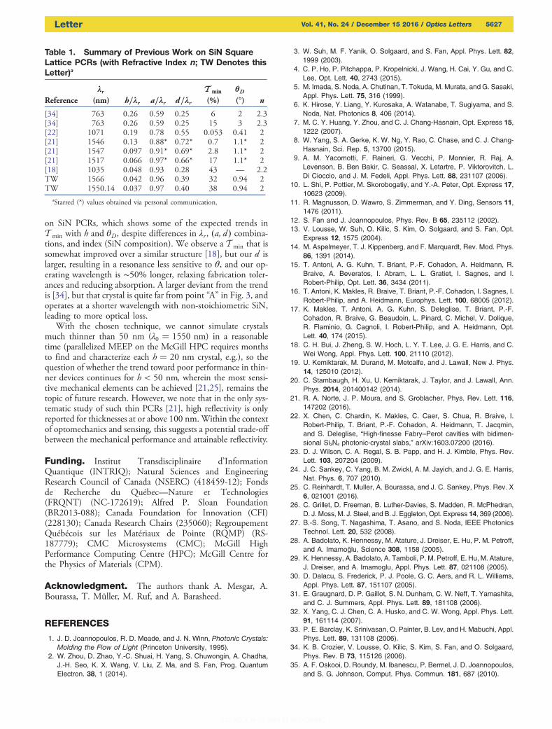
on SiN PCRs, which shows some of the expected trends inT min with h and θD, despite differences in λr , �a; d � combina-tions, and index (SiN composition). We observe a T min that issomewhat improved over a similar structure [18], but our d islarger, resulting in a resonance less sensitive to θ, and our op-erating wavelength is ∼50% longer, relaxing fabrication toler-ances and reducing absorption. A larger deviant from the trendis [34], but that crystal is quite far from point “A” in Fig. 3, andoperates at a shorter wavelength with non-stoichiometric SiN,leading to more optical loss.
With the chosen technique, we cannot simulate crystalsmuch thinner than 50 nm (λ0 � 1550 nm) in a reasonabletime (parallelized MEEP on the McGill HPC requires monthsto find and characterize each h � 20 nm crystal, e.g.), so thequestion of whether the trend toward poor performance in thin-ner devices continues for h < 50 nm, wherein the most sensi-tive mechanical elements can be achieved [21,25], remains thetopic of future research. However, we note that in the only sys-tematic study of such thin PCRs [21], high reflectivity is onlyreported for thicknesses at or above 100 nm.Within the contextof optomechanics and sensing, this suggests a potential trade-offbetween the mechanical performance and attainable reflectivity.
Funding. Institut Transdisciplinaire d’InformationQuantique (INTRIQ); Natural Sciences and EngineeringResearch Council of Canada (NSERC) (418459-12); Fondsde Recherche du Québec—Nature et Technologies(FRQNT) (NC-172619); Alfred P. Sloan Foundation(BR2013-088); Canada Foundation for Innovation (CFI)(228130); Canada Research Chairs (235060); RegroupementQuébécois sur les Matériaux de Pointe (RQMP) (RS-187779); CMC Microsystems (CMC); McGill HighPerformance Computing Centre (HPC); McGill Centre forthe Physics of Materials (CPM).
Acknowledgment. The authors thank A. Mesgar, A.Bourassa, T. Müller, M. Ruf, and A. Barasheed.
REFERENCES
1. J. D. Joannopoulos, R. D. Meade, and J. N. Winn, Photonic Crystals:Molding the Flow of Light (Princeton University, 1995).
2. W. Zhou, D. Zhao, Y.-C. Shuai, H. Yang, S. Chuwongin, A. Chadha,J.-H. Seo, K. X. Wang, V. Liu, Z. Ma, and S. Fan, Prog. QuantumElectron. 38, 1 (2014).
3. W. Suh, M. F. Yanik, O. Solgaard, and S. Fan, Appl. Phys. Lett. 82,1999 (2003).
4. C. P. Ho, P. Pitchappa, P. Kropelnicki, J. Wang, H. Cai, Y. Gu, and C.Lee, Opt. Lett. 40, 2743 (2015).
5. M. Imada, S. Noda, A. Chutinan, T. Tokuda, M. Murata, and G. Sasaki,Appl. Phys. Lett. 75, 316 (1999).
6. K. Hirose, Y. Liang, Y. Kurosaka, A. Watanabe, T. Sugiyama, and S.Noda, Nat. Photonics 8, 406 (2014).
7. M. C. Y. Huang, Y. Zhou, and C. J. Chang-Hasnain, Opt. Express 15,1222 (2007).
8. W. Yang, S. A. Gerke, K. W. Ng, Y. Rao, C. Chase, and C. J. Chang-Hasnain, Sci. Rep. 5, 13700 (2015).
9. A. M. Yacomotti, F. Raineri, G. Vecchi, P. Monnier, R. Raj, A.Levenson, B. Ben Bakir, C. Seassal, X. Letartre, P. Viktorovitch, L.Di Cioccio, and J. M. Fedeli, Appl. Phys. Lett. 88, 231107 (2006).
10. L. Shi, P. Pottier, M. Skorobogatiy, and Y.-A. Peter, Opt. Express 17,10623 (2009).
11. R. Magnusson, D. Wawro, S. Zimmerman, and Y. Ding, Sensors 11,1476 (2011).
12. S. Fan and J. Joannopoulos, Phys. Rev. B 65, 235112 (2002).13. V. Lousse, W. Suh, O. Kilic, S. Kim, O. Solgaard, and S. Fan, Opt.
Express 12, 1575 (2004).14. M. Aspelmeyer, T. J. Kippenberg, and F. Marquardt, Rev. Mod. Phys.
86, 1391 (2014).15. T. Antoni, A. G. Kuhn, T. Briant, P.-F. Cohadon, A. Heidmann, R.
Braive, A. Beveratos, I. Abram, L. L. Gratiet, I. Sagnes, and I.Robert-Philip, Opt. Lett. 36, 3434 (2011).
16. T. Antoni, K. Makles, R. Braive, T. Briant, P.-F. Cohadon, I. Sagnes, I.Robert-Philip, and A. Heidmann, Europhys. Lett. 100, 68005 (2012).
17. K. Makles, T. Antoni, A. G. Kuhn, S. Deleglise, T. Briant, P.-F.Cohadon, R. Braive, G. Beaudoin, L. Pinard, C. Michel, V. Dolique,R. Flaminio, G. Cagnoli, I. Robert-Philip, and A. Heidmann, Opt.Lett. 40, 174 (2015).
18. C. H. Bui, J. Zheng, S. W. Hoch, L. Y. T. Lee, J. G. E. Harris, and C.Wei Wong, Appl. Phys. Lett. 100, 21110 (2012).
19. U. Kemiktarak, M. Durand, M. Metcalfe, and J. Lawall, New J. Phys.14, 125010 (2012).
20. C. Stambaugh, H. Xu, U. Kemiktarak, J. Taylor, and J. Lawall, Ann.Phys. 2014, 201400142 (2014).
21. R. A. Norte, J. P. Moura, and S. Groblacher, Phys. Rev. Lett. 116,147202 (2016).
22. X. Chen, C. Chardin, K. Makles, C. Caer, S. Chua, R. Braive, I.Robert-Philip, T. Briant, P.-F. Cohadon, A. Heidmann, T. Jacqmin,and S. Deleglise, “High-finesse Fabry–Perot cavities with bidimen-sional Si3N4 photonic-crystal slabs,” arXiv:1603.07200 (2016).
23. D. J. Wilson, C. A. Regal, S. B. Papp, and H. J. Kimble, Phys. Rev.Lett. 103, 207204 (2009).
24. J. C. Sankey, C. Yang, B. M. Zwickl, A. M. Jayich, and J. G. E. Harris,Nat. Phys. 6, 707 (2010).
25. C. Reinhardt, T. Muller, A. Bourassa, and J. C. Sankey, Phys. Rev. X6, 021001 (2016).
26. C. Grillet, D. Freeman, B. Luther-Davies, S. Madden, R. McPhedran,D. J. Moss, M. J. Steel, and B. J. Eggleton, Opt. Express 14, 369 (2006).
27. B.-S. Song, T. Nagashima, T. Asano, and S. Noda, IEEE PhotonicsTechnol. Lett. 20, 532 (2008).
28. A. Badolato, K. Hennessy, M. Atature, J. Dreiser, E. Hu, P. M. Petroff,and A. Imamoğlu, Science 308, 1158 (2005).
29. K. Hennessy, A. Badolato, A. Tamboli, P. M. Petroff, E. Hu, M. Atature,J. Dreiser, and A. Imamoglu, Appl. Phys. Lett. 87, 021108 (2005).
30. D. Dalacu, S. Frederick, P. J. Poole, G. C. Aers, and R. L. Williams,Appl. Phys. Lett. 87, 151107 (2005).
31. E. Graugnard, D. P. Gaillot, S. N. Dunham, C. W. Neff, T. Yamashita,and C. J. Summers, Appl. Phys. Lett. 89, 181108 (2006).
32. X. Yang, C. J. Chen, C. A. Husko, and C. W. Wong, Appl. Phys. Lett.91, 161114 (2007).
33. P. E. Barclay, K. Srinivasan, O. Painter, B. Lev, and H. Mabuchi, Appl.Phys. Lett. 89, 131108 (2006).
34. K. B. Crozier, V. Lousse, O. Kilic, S. Kim, S. Fan, and O. Solgaard,Phys. Rev. B 73, 115126 (2006).
35. A. F. Oskooi, D. Roundy, M. Ibanescu, P. Bermel, J. D. Joannopoulos,and S. G. Johnson, Comput. Phys. Commun. 181, 687 (2010).
Table 1. Summary of Previous Work on SiN SquareLattice PCRs (with Refractive Index n; TW Denotes thisLetter)a
Referenceλr
(nm) h∕λr a∕λr d∕λrT min
(%)θD(°) n
[34] 763 0.26 0.59 0.25 6 2 2.3[34] 763 0.26 0.59 0.25 15 3 2.3[22] 1071 0.19 0.78 0.55 0.053 0.41 2[21] 1546 0.13 0.88* 0.72* 0.7 1.1* 2[21] 1547 0.097 0.91* 0.69* 2.8 1.1* 2[21] 1517 0.066 0.97* 0.66* 17 1.1* 2[18] 1035 0.048 0.93 0.28 43 — 2.2TW 1566 0.042 0.96 0.39 32 0.94 2TW 1550.14 0.037 0.97 0.40 38 0.94 2
aStarred (*) values obtained via personal communication.
Letter Vol. 41, No. 24 / December 15 2016 / Optics Letters 5627


![Tuning of the Optical Properties in Photonic Crystals Made ... · optical devices. These structures, referred to as photonic crystals [3–11], are characterized by an unusual dispersion](https://img.pdfslide.net/doc/110x75/612fc90c1ecc51586943aca6/tuning-of-the-optical-properties-in-photonic-crystals-made-optical-devices.jpg)


![PORT: A PIEZOELECTRIC OPTICAL RESONANCE TUNER · 2018. 4. 13. · tuning step. This problem can be overcome with an overdamped design [11]. based on dual resonance modes,” CONCLUSIONS](https://img.pdfslide.net/doc/110x75/613efcbdc500cf75ab363c79/port-a-piezoelectric-optical-resonance-tuner-2018-4-13-tuning-step-this-problem.jpg)