Embed Size (px)
Citation preview
ICP/EXT-04-00330Revision 0
Preremedial Design Report
of Remediation Options for
OU 7-13/14
Gretchen E. Matthern
Neal Yancey
Gregory Hulet
Peter Shaw
September 2005

ICP/EXT-04-00330Revision 0
Project No. 24218
Preremedial Design Report of Remediation Options for OU 7-13/14
Gretchen E. Matthern Neal Yancey
Gregory Hulet Peter Shaw
Edited by Tasha Taylor and LauraLee Gourley
September 2005
Idaho Cleanup Project Idaho Falls, Idaho 83415
Prepared for the U.S. Department of Energy
Assistant Secretary for Environmental Management Under DOE Idaho Operations Office
Contract DE-AC07-05ID14516
iii
ABSTRACT
This report presents the results of tests determining the effectiveness of
treatment options for radioactive mixed waste and makes recommendations for
their use in remediating the Subsurface Disposal Area, a radioactive landfill that
is part of the Radioactive Waste Management Complex at the Idaho National
Laboratory. The treatment options—in situ thermal desorption, in situ grouting,
and ex situ grouting—were tested using transuranic waste from the landfill and
surrogate.
The testing provides additional data that will aid the U.S. Department of
Energy in determining the effectiveness of these options as treatments for waste
at the landfill. These data will be used in preparing the remedial investigation and
feasibility study for Waste Area Group 7, Operable Unit 7-13/14, to help evaluate
the safety, effectiveness, and risk of these alternatives considered for the
feasibility study. Remediation is being performed under the Comprehensive
Environmental Response, Compensation, and Liability Act.

iv

v
EXECUTIVE SUMMARY
This report presents the results of testing based on the Test Plan for the Evaluation of In Situ
Thermal Desorption and Grouting Technologies for Operable Unit 7-13/14 (Yancey et al. 2003) and
makes recommendations for consideration during ongoing development of the feasibility study for
Operable Unit (OU) 7-13/14. When the test plan was being prepared, the three treatment options (in situ
thermal desorption [ISTD], in situ grouting [ISG], and ex situ grouting [ESG]) included in it were being
evaluated and were all under consideration for use in developing remedial alternatives for the feasibility
study. Since the test plan was written, data gathered through the test plan evaluations, the Second Addendum to the Work Plan for the OU 7-13/14 Waste Area Group 7 Comprehensive Remedial Investigation/Feasibility Study (Holdren and Broomfield 2004), and the Feasibility Study Preliminary
Documented Safety Analysis for In Situ Thermal Desorption in the Subsurface Disposal Area(Abbott 2003) have led to the elimination of ISTD as a treatment option for the feasibility study. The
results, conclusions, and recommendations from ISTD testing are included in this report to document
testing conducted as a part of the test plan.
Grouts under consideration for ISG—neata and with various admixtures—were tested for
(1) durability, (2) characteristics that tend toward leaching or binding of contaminants, and (3) data to
support contaminant transport modeling for treated waste forms. For ISTD testing, major emissions were
quantified as waste and soil were slowly heated to determine the degree of hazardous organic contaminant
and nitrate removal or destruction from the test samples. These tests were guided by the Test Plan for the Evaluation of In Situ Thermal Desorption and Grouting Technologies for Operable Unit 7-13/14
(Yancey et al. 2003).
This report provides additional data for the U.S. Department of Energy to aid in determining the
effectiveness of ISG and ESG as treatments for waste at the Subsurface Disposal Area (SDA). Some of
the data generated during these tests will support the remedial investigation and feasibility study for
Waste Area Group 7 OU 7-13/14.b The SDA is being remediated under the Comprehensive
Environmental Response, Compensation, and Liability Act (42 USC § 9601 et seq., 1980). The tests
reported in this document address the Comprehensive Environmental Response, Compensation, and
Liability Act criteria of effectiveness, both near and long term; reduction in mobility of contaminants
through stabilization; and implementability. This document follows the organization and processes
identified in guidance from the U.S. Environmental Protection Agency (EPA 1992).
In situ thermal desorption is commercially available and has been applied successfully at sites
containing soil contaminated with organics (TerraTherm 2005a; Vinegar et al. 1998; Vinegar, Stegemeier,
and Sheldon 1997); however, ISTD has not been demonstrated at sites containing buried containerized
waste, radionuclides, nitrate salts, reactive mixtures, or large amounts of metal debris. The ISTD process
under consideration uses electric resistance heaters to heat a region of the subsurface soil and waste to a
prescribed temperature. Vapors generated by this heating process are collected and treated by an
aboveground off-gas system. In situ thermal desorption can reduce the amount of contaminants in the
subsurface by volatilization or, at higher temperatures, by degradation. Results from bench- and
drum-scale tests and other evaluations (Abbott 2003) have shown that there are conditions where there is
the potential to have uncontrolled reactions. In addition, there are conditions where ISTD may increase
a Neat grout refers to any of the grout formulas that are used at 100% grout without waste or other additives. The neat grout was
used as a baseline condition and compared with results when grouts were mixed with various waste loadings.
b. The Federal Facility Agreement and Consent Order (DOE-ID 1991) lists 10 WAGs for INL. Each WAG is subdivided into
OUs. The RWMC is identified as WAG 7 and originally contained 14 OUs. Operable Unit 7-13 (TRU pits and trenches RI/FS)
and OU 7-14 (WAG 7 comprehensive RI/FS) ultimately were combined into the OU 7-13/14 comprehensive RI/FS for WAG 7.
vi
the mobility of some contaminants of concern. Because of these findings, ISTD is not recommended as a
stand-alone treatment or a pretreatment for ISG at the SDA.
In situ grouting is being considered for treatment of transuranic (TRU) pits and trenches, and
non-TRU pits and trenches and soil vault rows. Jet grouting is the specific ISG technique being
considered for buried waste within the SDA. Jet grouting uses a specially designed rotary percussion drill
rig to deliver and intimately mix grout with soil, debris, and contaminants in the subsurface. For purposes
of this report, ISG will refer to jet grouting. The grout is injected at approximately 6,000 psi through
small nozzles; high pressure combined with dense grout provides the energy required to mix the grout and
subsurface materials. Each injection of grout in homogenous soil forms a column, and a series of
diagonally offset columns forms a contiguous set of columns or monolith. Injection of grout in
nonhomogenous waste can form columns with more variation in diameter, depending on voids and types
of containers, but still interconnecting to form a monolith when a series of columns is placed in waste.
Grout must be designed specifically for ISG to meet the viscosity, particle size, and set times
required for effective operation of the grouting rig. Past bench- and field-scale testing have demonstrated
effectiveness and implementability of four of the grouts being tested. GMENT-12, U.S. Grout, TECT
HG, and WAXFIX grout materials have been evaluated for leaching and physical characteristics to
develop a recommendation of a single material for each application. Previous tests were conducted by
Loomis et al. (2003) for application to TRU waste. The tests completed for this report were applicable to
TRU, non-TRU, and Pad A waste. In addition to the proprietary grout formulations, five nonproprietary
cementitious grout formulations (Portland cement, Portland cement with fly ash, Portland cement with
slag, Portland cement with fly ash and thiosulfate, and Portland cement with slag and thiosulfate) were
evaluated for immobilization of non-TRU radionuclides in soil. The primary component of each of these
formulations, Portland cement, is the same as for GMENT-12, U.S. Grout, and TECT HG, making them
viable alternatives for jet grouting; however, some additional tests would need to be conducted to verify
that the nonproprietary grouts can be jet grouted and that they meet implementability criteria (Shaw
2004).
Ex situ grouting (solidification) is being considered for treatment of the Pad A salt waste. Ex situ
grouting includes selection of an appropriate grout and an approach to transfer the waste from Pad A to a
mixing system. This report examines only grout selection. Three candidate groutsc have been identified
for testing as an ESG: Polysiloxane, Saltstone, and WAXFIX. Portland cement and other nonproprietary
grouts generally do not handle high salt loads such as those that would be present in Pad A waste.
The tests in this report address six main objectives from Yancey et al. (2003):
Develop data to support contaminant transport modeling for treated waste forms. Data
obtained from these tests will be used in modeling migration of contaminants in the final waste
form after ISG or ESG. In addition, these data will be used to determine changes in leachability of
actinides from waste and surrounding soil following ISTD heating. These data will support
modeling to estimate the release rate of contaminants from the treated waste and compare it to the
predicted release rate from untreated waste. The test results also will support risk assessment, risk
modeling, and performance evaluation portions of the feasibility study for OU 7-13/14.
c. Dimethyl Polysiloxane, marketed by Technology Visions Group, uses a polymer encapsulation technology (Loomis, Miller,
and Prewett 1997) shown to successfully encapsulate surrogate salt materials. Saltstone grout, developed by Savannah River Site,
has been developed for salt encapsulation. WAXFIX also is considered in the in situ portion of Yancey et al. (2003).
vii
Evaluate durability of grouted waste. Physical property data will be obtained to compare grouts
and waste loadings. Long-term physical stability of the grouted waste forms will be estimated from
these near-term tests.
Evaluate WAXFIX for use as a grout. The purpose of these tests is to understand better the
advantages and limitations of WAXFIX as a grout for TRU and non-TRU waste. Data will be used
to address potential criticality and reactivity concerns that may be encountered with specific types
and concentrations of contaminants. The ability of WAXFIX to contain radionuclides and nitrates
is evaluated. In addition, the generation rate of hydrogen gas for WAXFIX mixed with
radionuclides will be assessed because of the radiolysis process.
Quantify major emissions as waste and soil are slowly heated. Determining primary off-gas
constituents and concentrations as waste and soil are heated will help identify the off-gas
processing requirements for full-scale test planning. The carbon monoxide and carbon dioxide
releases determine the relative amounts of combustion and pyrolysis occurring. The gas proportion
measurements also could assist in monitoring the type of waste being heated and any nitrate
organic reactions. In addition, these data will support the generation of safety and design data for
OU 7-13/14.
Determine the degree of hazardous organic contaminant and nitrate removal or destruction
from soil and waste. Quantifying the removal or destruction of chlorinated volatile organic
compounds (VOCs) and nitrate salts in the waste will help establish anticipated efficiency of
ISTD-mediated removal or destruction of contaminants of concern in TRU pits and trenches waste.
Data also will be used to generate design data for the pending feasibility study for OU 7-13/14.
Test potential mixtures of organics and nitrates for reactivity. Determining whether mixtures of
nitrate salt sludge and organic sludge will react exothermically during heating by ISTD will help
establish temperature ranges to avoid such reactions.
The ISTD testing raised, as well as answered, questions about applicability of ISTD to the SDA.
Nitrate salts are expected to react exothermically with various forms of carbon in the waste. As shown
most clearly in the thermal gravimetric analysis tests, the chemical form of carbon and rate of temperature
increase of the system affect the magnitude and intensity of the reaction. The drum-scale reactivity
experiments failed to demonstrate a method to heat nitrate salt surrogate and carbon-containing materials
in a manner that maintained control over reaction between nitrate and carbon. Based on thermal
gravimetric analysis and drum-scale results, it may be possible to heat mixtures of nitrate and
carbon-containing waste in a manner that keeps the reaction under control, but it would require slow rates
of heating and control of hot-spot formation. In a heterogeneous, uncharacterized waste form
(i.e., containing organics and nitrates), such as exists in the SDA, the potential for uncontrolled
exothermic reactions exist. Therefore, ISTD could not be implemented safely based on the results of the
bench- and drum-scale tests.
In situ thermal desorption should be able to remove VOCs and oils from the subsurface through a
combination of volatilization, oxidation, and reduction. The fate of radionuclides during ISTD cannot be
conclusively stated based on data collected during this testing. Elimination of organic compounds and
nitrate would simplify and improve the overall performance of grout in the waste; however, all of the
grouts tested can tolerate the presence of some amount of organic and nitrate compounds. Elimination of
only the VOCs would significantly reduce the inventory of chlorinated organic compounds, some of
which are contaminants of concern, and would reduce by about half the total mass of organic compounds
present in the waste. The removal of VOCs could likely be done at temperatures below 230°C (446°F) to
avoid the nitrate-cellulose reaction, but additional testing and modeling would be required to demonstrate
viii
the technical and economic feasibility of this approach. By reducing the total mass, grouting will work
more effectively by increasing the amount of grout that can be injected into the waste, thus decreasing the
waste-to-grout ratio; however, because of the potential for uncontrolled exothermic reactions and the
potential to increase contaminant mobility in some cases, ISTD is not recommended at the SDA.
The ISG tests did not demonstrate one grout formulation to be significantly better than the other
grout formulations for all radionuclides and waste forms evaluated. The waste loadings used in the leach
tests were determined by the maximum amount of waste or surrogate that could be added to the grout and
still maintain a cohesive sample. Although the leach index was expected to decrease as waste loading
increased, this was not observed. For many of the samples containing TRU isotopes (i.e., uranium,
americium, plutonium, and neptunium), the concentrations of radionuclides in the leachate were below
the detection limit; therefore, the leach index was calculated from the detection limit. For the samples
containing TRU isotopes, most of the leach indices (with the exception of neptunium) are greater than 10,
indicating low effective diffusivity and high resistance to leaching. Because most data came back
nondetectable, the leach indices did not vary much either.
Radionuclides were added at concentrations that were detectable in the untreated waste; therefore,
all of the grouts were successful at reducing the leachability of the radionuclides tested. If the grout
functions only as a macroencapsulation agent, then chemistry of the radionuclide is not important. If the
grout immobilizes contaminants through a combination of chemical interaction and macroencapsulation,
such as is the case with cementitious formulations, then chemistry of the contaminant is important. For
this reason, the TRU radionuclides may behave differently from non-TRU radionuclides, with respect to
leaching, when grouted in cementitious materials. The leach index values for all the radionuclides (TRU
and non-TRU) were approximately the same in WAXFIX. This is not surprising since WAXFIX works
by encapsulation of the contaminant. For all of the samples containing non-TRU isotopes (i.e., carbon,
technetium, and iodine), concentrations of the radionuclides in the leachate were above detection limits.
The leach index of non-TRU isotopes was generally lower than that for TRU isotopes in U.S. Grout and
TECT HG. Cementitious grouts immobilize contaminants through a combination of chemical interaction
and encapsulation. The difference seen between the two classes of radionuclides within the cementitious
grouts is probably caused by a difference in the chemical interactions between the radionuclides and the
grouts.
The radionuclide, as well as the type of waste matrix, is important to evaluating a grout for use as a
stabilization material. Compressive strength, porosity, and hydraulic conductivity are important
parameters to consider when evaluating the immobilization potential of a grout for a specific contaminant,
but none of them are a direct indicator of leach resistance. The addition of waste materials generally
decreased the compressive strength and increased the hydraulic conductivity and porosity of the grouts
compared to neat grout samples. These measurements suggest that the ability of grouts to immobilize
contaminants decreased with the presence of waste. Based on results of ANS leach tests conducted on
grouted samples alone, there is no clear best choice among formulations of grouts tested for all types of
waste and contaminants. Based on current testing and past studies, the strongest performing grouts,
considering physical properties, leaching, and cost, for each class of contaminant and waste are as
follows:
For TRU contaminants in soil, four grouts were evaluated: WAXFIX, GMENT-12, U.S. Grout, and
TECT HG. In areas where physical support and immobilization of contaminants is needed,
GMENT-12 would be preferred, as it performed the best overall.
ix
For TRU contaminants in organic sludge, four grouts were evaluated: WAXFIX, GMENT-12,
U.S. Grout, and TECT HG. In this case, all of the grouts performed equally well at reducing
leachability of TRU contaminants, but GMENT-12 had the highest compressive strength. If
organic sludge is to be grouted and if compressive strength is important, then GMENT-12 would
be the best choice.
For TRU contaminants in nitrate salt, five grouts were evaluated: WAXFIX, GMENT-12,
U.S. Grout, TECT HG, and Saltstone. In areas where carbon steel drums or nonmetal containers
were used to contain TRU contaminants in nitrate salt, the integrity of the containers is likely
already compromised, and jet grouting could be used to reduce the potential for contaminant
transport. Where ISG has been identified for use in nitrate salts, U.S. Grout is recommended
because it produces samples with the highest compressive strength and a comparable leach index to
the other grouts tested. WAXFIX also produced good leach-resistant samples and could withstand
high salt loadings; however, the compressive strength was not as good as U.S. Grout.
For non-TRU contaminants in soil, ten grout formulations were evaluated: WAXFIX, GMENT-12,
U.S. Grout, TECT HG, Saltstone, Portland cement, Portland cement with fly ash, Portland cement
with slag, Portland cement with fly ash and thiosulfate, and Portland cement with slag and
thiosulfate. Portland cement with slag, Portland cement with slag and thiosulfate, WAXFIX, and
GMENT-12 would be the best and essentially equal choices for immobilization of C-14, Tc-99,
and I-129 in soil. Based on physical properties, GMENT-12 compared to Portland cement with slag
has the same compressive strength and porosity and lower hydraulic conductivity. WAXFIX
compared to GMENT-12 and Portland cement with slag has lower compressive strength, lower
porosity, and equal hydraulic conductivity. If cost is considered, then Portland cement with slag
will be the best choice.
WAXFIX is recommended for ESG of nitrate salt waste. Most Portland cement-based grouts do not
tolerate high loadings of salts. Based on the test results, Saltstone, a Portland cement-based grout,
might work effectively with some modification to the recipe used in this report. WAXFIX, a
paraffin based grout, was able to tolerate high concentrations of salts and maintain a cohesive
sample.
If ISG were used for physical support of a cap, then a cementitious grout would be the preferred
choice. Overall, Portland cement with slag, GMENT-12, or U.S. Grout would be the best choices
for physical support of the cap. Based on unconfined compressive-strength tests, GMENT-12 was
the most tolerant of organic sludge, U.S. Grout was the most tolerant of nitrate salt, and soil was
tolerated equally by all three. Since nonproprietary grouts, such as Portland cement with slag, are
expected to be less expensive than proprietary grouts, and since volume percentage of organic
sludge and nitrate salt waste in the SDA is relatively small, Portland cement with slag is
recommended for use as a cap support grout in the SDA.

x
xi
ACKNOWLEDGEMENTS
This report embodies the cooperative effort of numerous technical and support staff, without whose
many contributions and commitment to excellence this work would not have been possible. The authors
would like to recognize and express their gratitude to John Dick, Rick Demmer, Bruce Mincher, Robert
Kirkham, Kristine Baker, Alan Herbst, Steve Johnson, and Marvin Banks who performed experimental
work, drafted appendixes, and contributed to sections of this report.

xii
xiii
CONTENTS
ABSTRACT.................................................................................................................................................iii
EXECUTIVE SUMMARY .......................................................................................................................... v
ACKNOWLEDGEMENTS......................................................................................................................... xi
ACRONYMS............................................................................................................................................. xxi
1. INTRODUCTION.............................................................................................................................. 1
1.1 Purpose .................................................................................................................................. 1
1.2 Scope ..................................................................................................................................... 3
1.3 Site Description ..................................................................................................................... 3
1.3.1 Brief History of Site Operations.......................................................................... 5
1.4 Description of Buried Waste ................................................................................................. 5
1.4.1 Organic Sludge Waste and Surrogate.................................................................. 5
1.4.2 Pad A Waste and Nitrate Salt Sludge.................................................................. 6
1.4.3 Inorganic Sludge Surrogate................................................................................. 6
1.5 Document Organization......................................................................................................... 6
2. DESCRIPTION OF TREATMENT TECHNOLOGIES.................................................................... 7
2.1 In Situ Thermal Desorption ................................................................................................... 7
2.2 In Situ Grouting..................................................................................................................... 9
2.3 Ex Situ Grouting.................................................................................................................. 11
3. TESTING ......................................................................................................................................... 11
4. DATA ANALYSIS AND INTERPRETATION—ISTD................................................................. 12
4.1 Develop Data to Support Contaminant Transport Modeling for Treated Waste Forms...... 13
4.1.1 Partition Coefficients for ISTD-Treated Nonradioactive Surrogates................ 13
4.1.2 Partition Coefficients for ISTD-Treated Transuranic Surrogates and Waste.... 16
4.1.3 Conclusions for Contaminant Transport Modeling for ISTD ........................... 19
4.2 Quantify Major Emissions as Waste and Soil are Slowly Heated....................................... 19
4.2.1 MSE Drum Tests............................................................................................... 19
4.2.2 Off-Gas, Bench-Scale Filter, and Mass Balance Analysis during ISTD of
Transuranic Surrogates and Waste.................................................................... 27

xiv
4.3 Determine the Degree of Hazardous Organic Contaminant and Nitrate Removal or
Destruction from Soil and Waste ........................................................................................ 35
4.3.1 MSE Drum Test ................................................................................................ 36
4.3.2 ISTD with Radioactive Surrogates and Waste .................................................. 36
4.4 Test Potential Mixtures of Organics and Nitrates for Reactivity ........................................ 36
4.4.1 Thermal Gravimetric and Differential Scanning Calorimetry Testing.............. 37
4.4.2 Testing at the Energetics Materials Research and Testing Center .................... 43
4.4.3 Reactivity Summary.......................................................................................... 48
5. DATA ANALYSIS AND INTERPRETATION—IN SITU GROUTING...................................... 48
5.1 Evaluate Durability of Grouted Waste ................................................................................ 48
5.1.1 Compressive Strength ....................................................................................... 48
5.1.2 Porosity ............................................................................................................. 53
5.1.3 Hydraulic Conductivity..................................................................................... 55
5.1.4 Durability Summary.......................................................................................... 57
5.2 Develop Data to Support Contaminant Transport Modeling for Treated Waste Forms...... 58
5.2.1 Leaching—In Situ Grouting of Nontransuranic Part 1 ..................................... 58
5.2.2 Leaching—In Situ Grouting of Nontransuranic Part 2 ..................................... 59
5.2.3 Leaching—In Situ Grouting of Transuranic Waste .......................................... 61
5.2.4 Leaching—In Situ Grouting of ISTD................................................................ 69
5.2.5 In Situ Grouting Contaminant Transport Summary .......................................... 72
5.3 Evaluate WAXFIX for Use as a Grout................................................................................ 76
5.3.1 Hydrogen Generation ........................................................................................ 76
5.3.2 Boron Retention ................................................................................................ 77
5.3.3 U.S. Department of Transportation Oxidizer .................................................... 77
5.3.4 WAXFIX Conclusions ...................................................................................... 78
6. DATA ANALYSIS AND INTERPRETATION—EX SITU GROUTING..................................... 78
7. QUALITY ASSURANCE AND QUALITY CONTROL ............................................................... 80
8. CONCLUSIONS AND RECOMMENDATIONS........................................................................... 81
8.1 Conclusions ......................................................................................................................... 81
8.1.1 In Situ Thermal Desorption............................................................................... 81
8.1.2 In Situ Grouting................................................................................................. 82
8.1.3 Ex Situ Grouting ............................................................................................... 85
8.2 Recommendations ............................................................................................................... 85
9. REFERENCES................................................................................................................................. 87
xv
Appendix A—Recipes for Surrogates, Grouts, and Other Materials........................................................A-1
Appendix B—Compressive-Strength Tests—Part 1................................................................................. B-1
Appendix C—Porosity Tests—Part 1 ....................................................................................................... C-1
Appendix D—Hydraulic Conductivity Tests—Part 1 ..............................................................................D-1
Appendix E—Boron Retention Tests ....................................................................................................... E-1
Appendix F—U.S. Department of Transportation Oxidizer Tests ............................................................F-1
Appendix G—Hydrogen-Generation Tests ..............................................................................................G-1
Appendix H—ISTD Reactivity: Differential Scanning Calorimetry........................................................H-1
Appendix I—Reactivity: MSE Drum Tests ................................................................................................I-1
Appendix J—ISTD Reactivity: Energetics Materials Research and Testing Center ................................. J-1
Appendix K—ISTD of Transuranic Waste Tests: Nonradioactive Surrogates.........................................K-1
Appendix L—ISTD of Transuranic Waste Tests: Radioactive Surrogates and Waste............................. L-1
Appendix M—In Situ Grouting of Transuranic Waste Tests .................................................................. M-1
Appendix N—In Situ Grouting of ISTD-Treated Transuranic Waste Tests.............................................N-1
Appendix O—In Situ Grouting of Nontransuranic Waste Tests—Part 1 .................................................O-1
Appendix P—In Situ Grouting of Nontransuranic Waste Tests—Part 2...................................................P-1
Appendix Q—Ex Situ Grouting of Pad A Nitrate Salt Tests....................................................................Q-1
Appendix R—Compressive-Strength Tests—Part 2................................................................................. R-1
Appendix S—Porosity Tests—Part 2 ........................................................................................................S-1
Appendix T—Hydraulic Conductivity Tests—Part 2............................................................................... T-1
FIGURES
1. Map showing Radioactive Waste Management Complex and other major facilities ......................... 2
2. Map of the Radioactive Waste Management Complex showing the location of the
Subsurface Disposal Area and types of buried waste.......................................................................... 4
3. Schematic of ISTD process................................................................................................................. 8
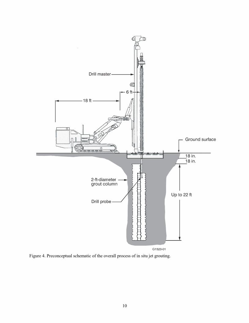
4. Preconceptual schematic of the overall process of in situ jet grouting ............................................. 10
xvi
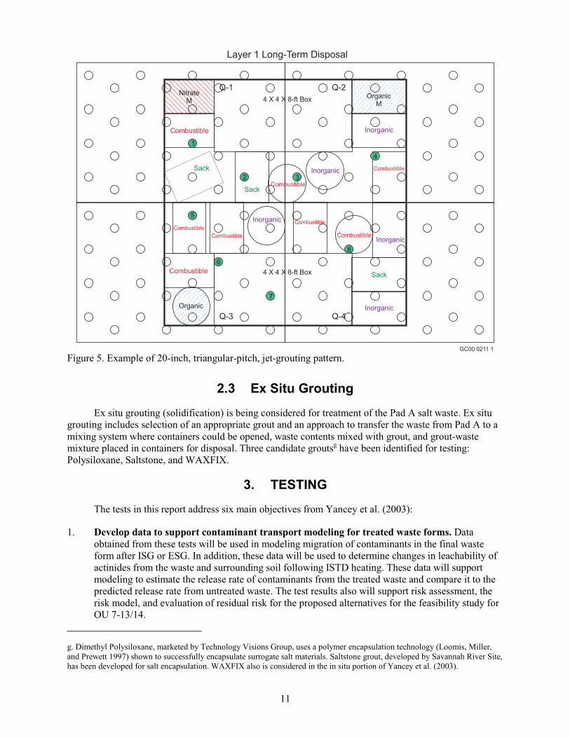
5. Example of 20-inch, triangular-pitch, jet-grouting pattern ............................................................... 11
6. Partition coefficients of rare earths from soil.................................................................................... 15
7. Partition coefficients for rare earths from inorganic sludge surrogate .............................................. 15
8. Partition coefficients for rare earths from organic sludge surrogate ................................................. 16
9. Partition coefficient for radionuclide-spiked soil pre-ISTD and post-ISTD at three
temperatures ...................................................................................................................................... 17
10. Partition coefficient for radionuclide-spiked inorganic sludge surrogate pre-ISTD
(20 C [68 F]) and post-ISTD at three temperatures ......................................................................... 18
11. Partition coefficients for radionuclides in organic sludge surrogate (no neptunium added)
and organic sludge waste pre-ISTD (20 C [68 F]) and post-ISTD (450 C [842 F]) ....................... 18
12. Temperatures of test drum contents .................................................................................................. 21
13. Generation of acid gas in organic sludge test, selected off-gas volatile organics, and
selected internal drum temperatures (Drum 1).................................................................................. 21
14. Off-gas hydrochloric acid observed during the test of Drum 3 organic sludge and
combustible debris ............................................................................................................................ 23
15. Off-gas volatile organic solvents observed during the test of Drum 3 organic sludge and
combustible debris ............................................................................................................................ 23
16. Off-gas hydrochloric acid observed during the test of Drum 4 organic sludge with
combustible debris and soil ............................................................................................................... 25
17. Off-gas volatile organic solvents observed during the test of Drum 4 organic sludge with
combustible debris and soil ............................................................................................................... 26
18. Carbon tetrachloride concentration in off-gas from ISTD as a function of time and
temperature for samples of organic sludge surrogate........................................................................ 28
19. Carbon tetrachloride concentration in off-gas from ISTD as a function of time and
temperature for samples of organic sludge waste ............................................................................. 28
20. Carbon tetrachloride concentration in off-gas from ISTD as a function of time and
temperature for samples of Pad A nitrate salt ................................................................................... 29
21. Carbon dioxide concentration in off-gas from ISTD as a function of time and
temperature for samples of organic sludge surrogate........................................................................ 30
22. Carbon dioxide concentration in off-gas from ISTD as a function of time and
temperature for samples of Pad A nitrate salt ................................................................................... 30
23. Nitrite and nitrate concentrations from off-gas in acid trap water for ISTD-treated
samples of Pad A nitrate salts and organic sludge waste .................................................................. 31
xvii
24. Concentrations of radionuclides on blank and soil ISTD filters ....................................................... 32
25. Concentrations of radionuclides on blank and inorganic sludge surrogate ISTD filters................... 32
26. Concentrations of radionuclides on blank and organic sludge surrogate ISTD filters...................... 33
27. Concentrations of radionuclides on blank and organic sludge waste ISTD filters............................ 33
28. Concentrations of radionuclides on blank and Pad A waste ISTD filters ......................................... 34
29. Cumulative mean percent mass change as a function of temperature and a duration of
four hours .......................................................................................................................................... 34
30. Thermal gravimetric analysis of nitrate salt surrogate run at 10 C (18 F)/minute ........................... 38
31. Thermal gravimetric analysis of organic sludge surrogate run at 1 C (1.8 F)/minute ..................... 39
32. Thermal gravimetric analysis of a mixture of 83 wt% nitrate salt surrogate and 17 wt%
carbon powder at 10 C (18 F)/minute .............................................................................................. 40
33. Thermal gravimetric analysis of a mixture containing excess carbon with respect to
nitrate salt surrogate run at 1 C (1.8 F)/minute ................................................................................ 40
34. Thermal gravimetric analysis of a mixture of 83 wt% nitrate salt surrogate and
17 wt% carbon powder at 0.1 C (0.18 F)/minute............................................................................. 41
35. Thermal gravimetric analysis of a mixture of nitrate salt surrogate and paraffin at 10 C
(18 F)/minute .................................................................................................................................... 42
36. Thermal gravimetric analysis of a mixture of nitrate salt surrogate (56 wt%) and
organic sludge surrogate (44 wt%) at 1 C (1.8 F)/minute................................................................ 43
37. Temperatures within drum during Phase 1 of Test 1: nitrate salt surrogate and graphite................. 44
38. Temperature of drum contents at several locations as a function of time for
Phase 2 of Test 1 ............................................................................................................................... 45
39. Temperature of drum contents at several positions as a function of time during Test 2................... 46
40. Temperature versus time for drum contents at three positions for drum Test 3—nitrate
salt with debris .................................................................................................................................. 47
41. Expansion of time period of greatest reactivity for temperature versus time for drum
contents at three positions for drum Test 3—nitrate salt with debris................................................ 47
42. Compressive strength of grout and grout-soil mixtures .................................................................... 49
43. Compressive strength for grout and grout-soil mixtures................................................................... 50
44. Combined results for initial and Phase 2 testing of compressive strength for grout
and grout-soil mixtures ..................................................................................................................... 50
xviii
45. Compressive strength of organic sludge and grout mixtures ............................................................ 51
46. Compressive strength with nitrate salt sludge surrogate ................................................................... 51
47. Compressive strength with ISTD-treated organic sludge as a surrogate........................................... 52
48. Porosity of grouted surrogate forms containing 0 and 50 wt% soil .................................................. 54
49. Porosity of grouted surrogate forms.................................................................................................. 55
50. Hydraulic conductivity of four grouts (WAXFIX, GMENT-12, TECT HG, or
U.S. Grout), neat (100 wt% grout), and mixed with one of three surrogates
(soil, organic sludge surrogate, or nitrate salt surrogate) (WAXFIX was tested at
70 wt% in soil and 60 wt% in nitrate salts)....................................................................................... 56
51. Hydraulic conductivity of four grouts (WAXFIX, GMENT-12, TECT HG, or
U.S. Grout), neat (100 wt% grout), and mixed with ISTD-treated organic sludge surrogate ........... 56
52. Hydraulic conductivity measurements for GMENT-12, Portland cement, and
Portland cement with slag at 0, 30, and 50 wt% of soil in grout....................................................... 57
53. Nontransuranic Part I testing, mean leach index for grout containing 50 wt% soil
spiked with technetium-99, iodine-129, neptunium, and carbon-14 ................................................. 59
54. Nontransuranic Parts 1 and 2 testing, mean leach index for grout containing 50 wt%
soil spiked with technetium-99, iodine-127, and carbon-14 ............................................................ 60
55. Leach indices for americium, uranium, neptunium, and plutonium from 30 wt%
Idaho National Laboratory soil and grout ......................................................................................... 62
56. Leach indices for americium, uranium, and plutonium from 5 wt% organic sludge
surrogate and grout............................................................................................................................ 63
57. Leach indices for americium, uranium, and plutonium from 9 wt% organic sludge
surrogate and grout............................................................................................................................ 63
58. Leach indices for grout and inorganic sludge at 30 wt% waste loading ........................................... 64
59. Leach indices for grout and inorganic sludge at 60 wt% waste loading ........................................... 65
60. Leach indices from nitrate salt sludge at 12 wt% (Pad A waste) ...................................................... 66
61. Leach indices for americium, uranium, and plutonium from 5 wt% organic sludge
waste and grout ................................................................................................................................. 67
62. Leach indices for americium, uranium, and plutonium from 9 wt% organic sludge waste
and GMENT-12 ................................................................................................................................ 68
63. Leach indices for americium, uranium, neptunium, and plutonium from 15 wt%
organic sludge waste and grout ......................................................................................................... 68
xix
64. Leach indices for americium for organic sludge surrogate and waste, with and
without ISTD treatment at 450 C (842 F) before grouting .............................................................. 70
65. Leach indices for uranium for organic sludge surrogate and waste, with and without
ISTD treatment at 450 C (842 F) before grouting............................................................................ 71
66. Leach indices for neptunium for organic sludge waste, with and without ISTD
treatment at 450 C (842 F) before grouting ..................................................................................... 71
67. Leach indices for plutonium for organic sludge surrogate and waste, with and
without ISTD treatment at 450 C (842 F) before grouting .............................................................. 72
68. Toxic characteristic leaching protocol results for chromium............................................................ 79
69. Compressive strength with nitrate salt sludge as a surrogate............................................................ 81
TABLES
1. Applicability of test objective to each technology ............................................................................ 13
2. Waste loadings used for hydraulic conductivity, porosity, and leach studies ................................... 52
3. Cement-based grout diffusion coefficients (cm²/s) ...........................................................................73
4. Minimum and maximum leach index values, based on standard deviations, for
contaminants in grouted waste: comparison of data presented in the Pacific Northwest
National Laboratory report to data presented in this report .............................................................. 74
5. Mass-normalized and volume-adjusted net hydrogen-generation rates ............................................ 77
6. American Nuclear Society leach index results for uranium.............................................................. 80
7. Calculated leach indices for nitrate ................................................................................................... 80

xx
xxi
ACRONYMS
ANS American Nuclear Society
COC contaminant of concern
DSC differential scanning calorimetry
EDTA ethylenediaminetetraacetic acid
ESG ex situ grouting
ICP-MS inductively coupled plasma-mass spectrometry
INL Idaho National Laboratory
ISG in situ grouting
ISTD in situ thermal desorption
Kd partition coefficient
OU operable unit
PNNL Pacific Northwest National Laboratory
RFP Rocky Flats Plant
RI/FS remedial investigation and feasibility study
RWMC Radioactive Waste Management Complex
SDA Subsurface Disposal Area
TGA thermal gravimetric analysis
TRU transuranic
VOC volatile organic compound
WAG waste area group

xxii
1
Preremedial Design Report of Remediation Options for OU 7-13/14
1. INTRODUCTION
This report presents results of testing based on the Test Plan for the Evaluation of In Situ Thermal
Desorption and Grouting Technologies for Operable Unit 7-13/14 (Yancey et al. 2003) and makes
recommendations for consideration during development of the feasibility study for Operable
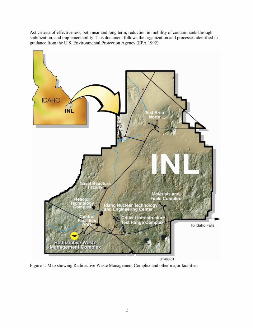
Unit 7-13/14. Grouting treatment options are being considered for radioactive waste buried in the
Subsurface Disposal Area (SDA), a radioactive landfill that is part of the Radioactive Waste Management
Complex (RWMC) at the Idaho National Laboratory (INL) Site (see Figure 1). The grouting treatment
options include in situ grouting (ISG) and ex situ grouting (ESG). In addition to grouting, in situ thermal
desorption (ISTD) was evaluated.
When the test plan (Yancey et al. 2003) was prepared, the three treatment options (ISTD, ISG, and
ESG) included in it were being evaluated and were all under consideration for use in developing remedial
alternatives for the feasibility study. Since the test plan was written, data gathered through the test plan
evaluations, the Second Addendum to the Work Plan for the OU 7-13/14 Waste Area Group 7 Comprehensive Remedial Investigation/Feasibility Study (Holdren and Broomfield 2004), and the
Feasibility Study Preliminary Documented Safety Analysis for In Situ Thermal Desorption in the
Subsurface Disposal Area (Abbott 2003) have led to the elimination of ISTD as a treatment option for the
feasibility study. The results, conclusions, and recommendations from ISTD testing are included in this
report to document the testing conducted as a part of the test plan by Yancey et al. (2003).
In situ grouting and ESG can physically stabilize waste and slow the release and migration of most
hazardous inorganics and radionuclides. In addition, ISG-treated areas of the SDA can minimize
subsidence and support a future surface barrier to reduce water infiltration into the waste. In situ thermal
desorption focuses on removal of organics but also can remediate nitrate salts and chlorinated organics in
organic sludge.
Grouts under consideration for ISG—neat and with various admixtures—were tested for
(1) durability, (2) characteristics that tend toward leaching or binding of contaminants, and (3) data to
support contaminant transport modeling for treated waste forms. For ISTD testing, major emissions,
quantified as waste and soil, were slowly heated to determine the degree of hazardous organic
contaminant and nitrate removal, or destruction from test samples. Potential mixtures of organics and
nitrates were tested for reactivity. These tests were guided by the test plan by Yancey et al. (2003).
1.1 Purpose
This report provides additional data for the U.S. Department of Energy to aid in determining the
effectiveness of ISG and ESG as treatments for waste at the SDA. Some of the data generated during
these tests will support the remedial investigation and feasibility study (RI/FS) for Waste Area Group
(WAG) 7 Operable Unit (OU) 13/14.a The SDA is being remediated under the Comprehensive
Environmental Response, Compensation, and Liability Act (42 USC § 9601 et seq., 1980). The tests
reported in this document address Comprehensive Environmental Response, Compensation, and Liability
a. The Federal Facility Agreement and Consent Order (DOE-ID 1991) lists 10 WAGs for INL. Each WAG is subdivided into
OUs. The RWMC is identified as WAG 7 and originally contained 14 OUs. Operable Unit 7-13 (TRU pits and trenches RI/FS)
and OU 7-14 (WAG 7 comprehensive RI/FS) ultimately were combined into the OU 7-13/14 comprehensive RI/FS for WAG 7.
2
Act criteria of effectiveness, both near and long term; reduction in mobility of contaminants through
stabilization; and implementability. This document follows the organization and processes identified in
guidance from the U.S. Environmental Protection Agency (EPA 1992).
Figure 1. Map showing Radioactive Waste Management Complex and other major facilities.
3
1.2 Scope
The tests reported in this document focus on thermal treatment and stabilization of radioactive
mixed waste buried in the SDA and follow Yancey et al. (2003). Twenty tests are described, and the
results are reported in this document.a Based on results of the originally planned tests, four tests
(hydraulic conductivity, porosity, compressive strength, and leaching) were repeated with four additional
grout formulations. Tests for ISTD and ISG used transuranic (TRU) waste from the SDA and surrogate.
The ISG tests also used surrogate non-TRU waste. The ESG bench tests used waste from Pad A.
A series of cold (nonradioactive) tests established the approach for hot (radioactive) testing. Hot
tests used surrogates spiked with radionuclides (isotopes of uranium, plutonium, americium, neptunium,
iodine, carbon, and technetium were used, as appropriate, for specific tests), waste material retrieved from
Pit 9 by the OU 7-10 Glovebox Excavator Method Project (DOE-ID 2004), and material from Pad A. All
preparations for hot testing, including safety documentation, were completed before accepting material
from Pit 9 or Pad A and are documented separately.
The screening process in Zitnik et al. (2002) streamlined the list of available remedial technologies
and process options, retaining for subsequent development and screening only those that met the criteria
adequately. The effectiveness of these remaining technologies is presented in this report through results of
bench and laboratory tests.
1.3 Site Description
The Idaho National Laboratory Site is located in southeastern Idaho and occupies 2,305 km2
(890 mi2) in the northeastern region of the Snake River Plain. Regionally, the INL Site is nearest to the
cities of Idaho Falls and Pocatello and to U.S. Interstate Highways I-15 and I-86. The INL Site extends
nearly 63 km (39 mi) from north to south, is about 58 km (36 mi) wide in its broadest southern portion,
and occupies parts of five southeast Idaho counties. Public highways (i.e., U.S. 20 and 26 and Idaho 22,
28, and 33) within the INL Site boundary and the Experimental Breeder Reactor I, which is a national
historic landmark, are accessible without restriction. Otherwise, access to INL Site is controlled.
Neighboring lands are used primarily for farming or grazing, or are in the public domain (e.g., national
forests and state-owned land) (Zitnik et al. 2002).
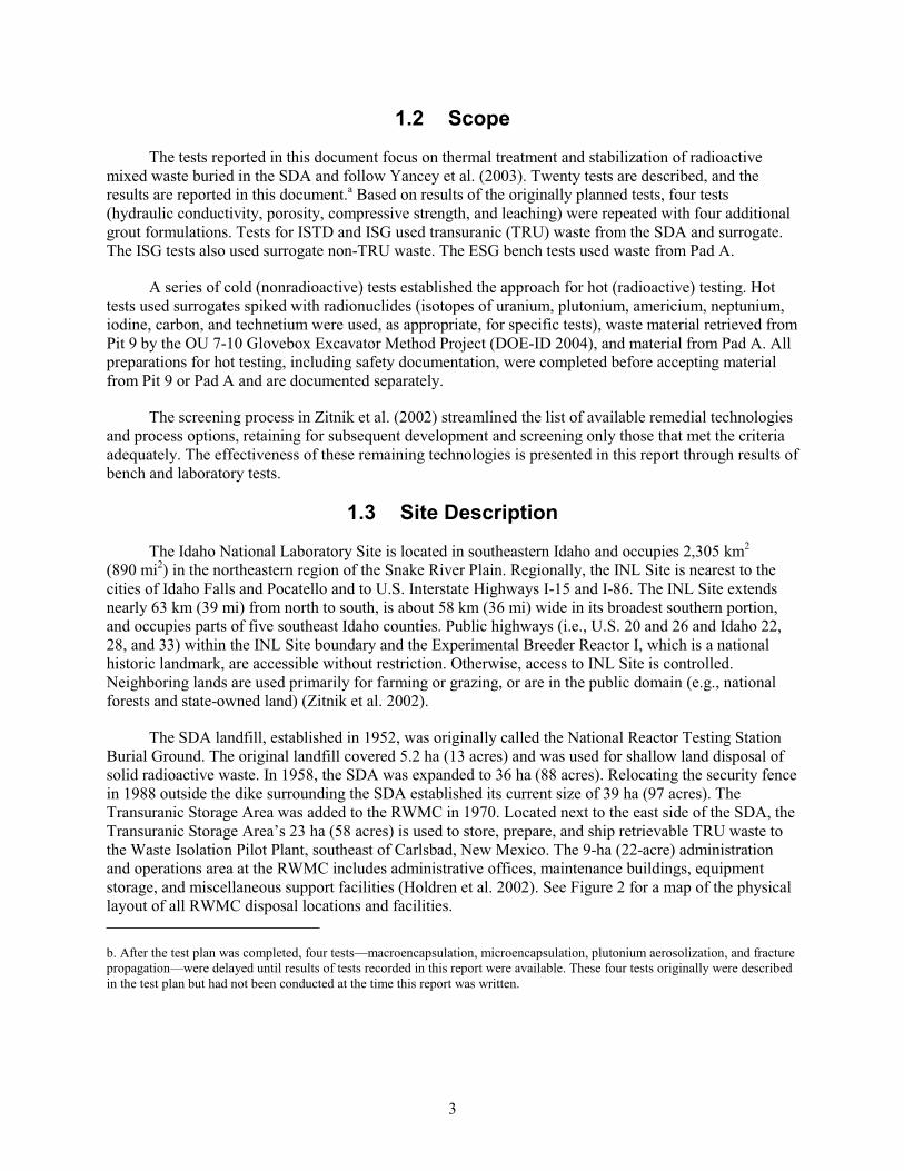
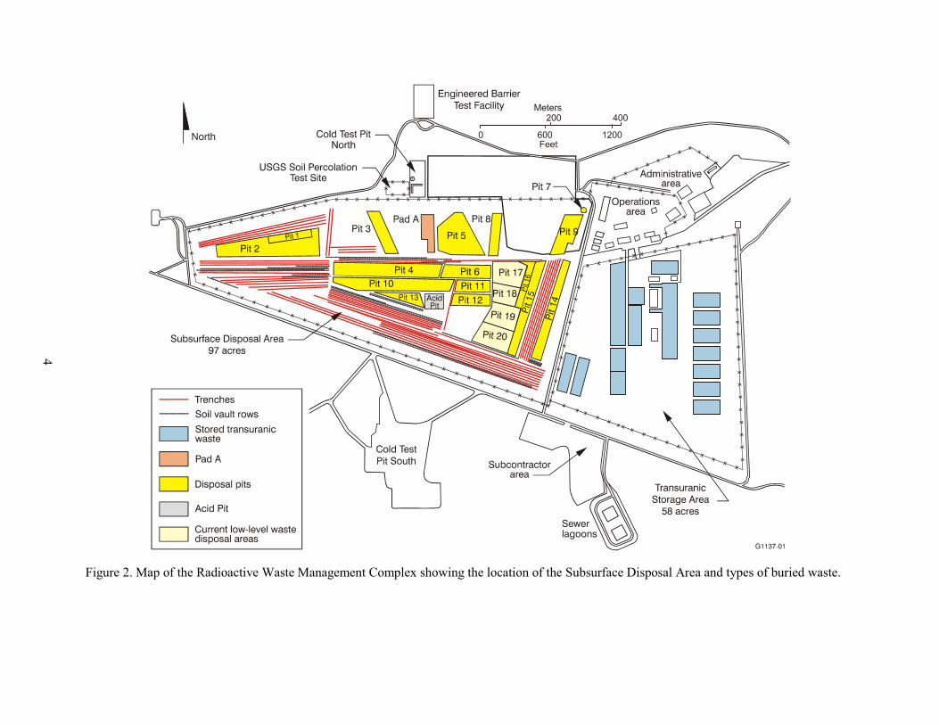
The SDA landfill, established in 1952, was originally called the National Reactor Testing Station
Burial Ground. The original landfill covered 5.2 ha (13 acres) and was used for shallow land disposal of
solid radioactive waste. In 1958, the SDA was expanded to 36 ha (88 acres). Relocating the security fence
in 1988 outside the dike surrounding the SDA established its current size of 39 ha (97 acres). The
Transuranic Storage Area was added to the RWMC in 1970. Located next to the east side of the SDA, the
Transuranic Storage Area’s 23 ha (58 acres) is used to store, prepare, and ship retrievable TRU waste to
the Waste Isolation Pilot Plant, southeast of Carlsbad, New Mexico. The 9-ha (22-acre) administration
and operations area at the RWMC includes administrative offices, maintenance buildings, equipment
storage, and miscellaneous support facilities (Holdren et al. 2002). See Figure 2 for a map of the physical
layout of all RWMC disposal locations and facilities.
b. After the test plan was completed, four tests—macroencapsulation, microencapsulation, plutonium aerosolization, and fracture
propagation—were delayed until results of tests recorded in this report were available. These four tests originally were described
in the test plan but had not been conducted at the time this report was written.
4
Figure 2. Map of the Radioactive Waste Management Complex showing the location of the Subsurface Disposal Area and types of buried waste.
5
1.3.1 Brief History of Site Operations
Disposal of mixed waste containing hazardous chemical and radioactive contaminants was allowed
through 1984. Since 1985, waste disposals in the SDA have been limited to low-level radioactive waste
generated at the INL Site. Construction, operation, and decommissioning of INL programs for nuclear
reactor testing have resulted in large volumes of waste. Various containers were used in shipping and
disposing of waste, including steel drums, cardboard cartons, and wooden boxes. Larger, individual
items—such as tanks, furniture, process and laboratory equipment, engines, and vehicles—were placed
separately as loose trash (Zitnik et al. 2002).
Contaminants—disposed of in shallow subsurface disposal units consisting of pits, trenches, and
soil vaults—include hazardous chemicals, remote-handled fission and activation products, and TRU
radionuclides. Disposals of TRU and mixed waste—mostly from Rocky Flats Plant (RFP) in Colorado—
were allowed through 1970. Radioactive waste from offsite sources originated from a variety of facilities,
including military and other defense agencies, universities, commercial operations, and the Atomic
Energy Commission (Zitnik et al. 2002).
1.4 Description of Buried Waste
Several waste types at the SDA include the nitrate salts in Pad A and combustibles, soil, and three
types of sludge (inorganic, organic, and nitrate salt) in TRU and non-TRU pits and trenches. Based on
recent mapping and burial records, nitrate or organic sludge drums are found in 20% or less of four pits
(Becker et al. 1998; Salomon et al. 2003). The density of organic sludge drums is usually less than
4.5 drums/m2; the density of nitrate salt drums is less than 1.6 drums/m
2. High-density areas greater than
this occur in less than 10% of the total drum area. Thus, areas of high density are rare.
The results presented in this report are from tests conducted with surrogates and wastes. The
surrogates were prepared based on the expected composition of the waste and with and without
radionuclides (hot and cold surrogates, respectively). The wastes wered samples retrieved from locations
within the SDA, that is organic sludge waste was retrieved from Pit 9 and Pad A waste was retrieved from
Pad A. The primary TRU contaminants of concern (COCs) that were used in this study are americium,
plutonium, uranium, and neptunium. The non-TRU COCs include technetium, iodine, and C-14
(Holdren et al. 2002).
1.4.1 Organic Sludge Waste and Surrogate
Organic sludge from Pit 9 contains chlorinated volatile organic COCs, such as trichloroethene,
trichloroethane, tetrachloroethene, methylene chloride, and carbon tetrachloride, in addition to the
TRU COCs (Holdren et al. 2002). Two different estimates of organic sludge waste compositions have
been developed based on several reports: Clements (1982), Vigil (1990), Liekhaus (1991), and Arrenholz
and Knight (1991). The earlier 1982 and 1989 assessments gave the approximate organic liquid content of
SDA sludge based on sludge preparation and shipping records. The 1991 assessments have been updated
based on the following:
d Samples were taken during operation of the OU 7-10 Glovebox Excavator Method Project, which retrieved 59 m3 (77 yd3) of
buried waste from the SDA during December 2003 and January 2004 (DOE-ID 2004). The purpose of the Glovebox Excavator
Method Project was to demonstrate the feasibility of waste retrieval, provide information on any COCs present in the
underburden, and characterize waste-zone material for safe and compliant storage pending a decision on final disposition. The
Glovebox Excavator Method Project operated under the Federal Facility Agreement and Consent Order for the Idaho National
Engineering Laboratory (DOE-ID 1991) and the “Comprehensive Environmental Response, Compensation and Liability Act of
1980 (CERCLA/Superfund)” (42 USC § 9601 et seq., 1980).
6
Calculations from recent vapor removal by the Organic Contamination in the Vadose Zone system
Newly found records as RFP sludge preparation areas are decontaminated
Recent shallow sampling of organic vapor between waste pits.
The current composition is now hypothesized to be 21 to 27 vol% Texaco Regal Oil,e 11 to
23 vol% miscellaneous oil, 20 to 37 vol% carbon tetrachloride, and 30 vol% other chlorinated
hydrocarbons (details of the composition are presented in Appendix A).
The primary halogenated hydrocarbon COC in the organic sludge is carbon tetrachloride. Calcium
silicate, Oil Dri, Microcel E, or other sorbent material was added as an absorbent for organic liquids
(Texaco Regal Oil) (Miller and Varvel 2005). The Texaco Regal Oil used at RFP is no longer
manufactured.
1.4.2 Pad A Waste and Nitrate Salt Sludge
Composition of Pad A waste includes salt at 30 wt% potassium nitrate and 60 wt% sodium nitrate
flakes with about 400 ppm soluble chromate (such as Cr+6
) and 180 pCi/g uranium as the primary
hazardous and radioactive components (a detailed composition is provided in Appendix A). While nitrate
and total chromium are issues with the nitrate salt sludge, the only contaminant of concern is uranium.
The primary components of nitrate salt sludge (RFP Series 745 sludge) are sodium nitrate and potassium
nitrate in an approximate 2-1 ratio. The composition of the Pad A waste and the nitrate salt sludge waste
are essentially the same. Since nitrate salt sludge waste was not retrieved from Pit 9, Pad A waste was
used for testing. Nitrate salt sludge surrogate (without radionuclides) was also prepared for testing as
required. The nitrate salt sludge COCs are nitrates and uranium (Holdren et al. 2002).
1.4.3 Inorganic Sludge Surrogate
The inorganic sludge surrogate formulation is based on average composition of inorganic
precipitates in original RFP Series 741 and 742 sludge (Landman 1981; Clements 1982) and previous
surrogates developed to represent this sludge (Low 1985; Low et al. 1987; Loomis and Low 1988) as
shown in Appendix A. The inorganic sludge surrogate will contain RWMC lake-bed soil, other inorganic
salt, water with terbium added, and nitrate salt. The RFP waste is estimated to have contained
40 to 70 wt% water, to which 10 to 20 wt% cement was added when the sludge was placed in drums.
At 20 wt% cement, the sludge-cement mixture would likely resemble a consolidated rather than an
unconsolidated material. To be conservative with respect to evaluating the performance of ISG and ISTD,
the amount of water and cement has been minimized to maximize the concentration of inorganic salts and
create an unconsolidated material. This approach is consistent with previous testing activities (Low 1985;
Low et al. 1987; Loomis and Low 1988).
1.5 Document Organization
The following paragraphs briefly describe the remaining sections in this report:
Section 2 describes treatment technologies under consideration
Section 3 introduces testing
e. References herein to any specific commercial product, process, or service by trade name, trademark, manufacturer, or
otherwise do not necessarily constitute or imply endorsement, recommendation, or favoring by the U.S. Government, any agency
thereof, or any company affiliated with the Idaho Cleanup Project at the Idaho National Laboratory Site.
7
Section 4 discusses each test series for ISTD and integrates the results
Section 5 discusses each test series for ISG and integrates the results
Section 6 discusses each test series for ESG and integrates the results
Section 7 contains conclusions and recommendations
Section 8 lists the references cited throughout this report
Appendix A contains the recipes used in the tests and details of compositions mentioned in the
body of the report
Appendixes B through T describe the study approach and test design and contain the results for
each test series.
2. DESCRIPTION OF TREATMENT TECHNOLOGIES
The following sections describe the three treatment technologies—ISTD, ISG, and ESG—for
which evaluation data were collected during this study.
2.1 In Situ Thermal Desorption
In situ thermal desorption is commercially available and has been applied successfully at sites
containing soil contaminated with organics (TerraTherm 2005a; Vinegar et al. 1998; Vinegar, Stegemeier,
and Sheldon 1997); however, ISTD has not been demonstrated at sites containing buried containerized
waste, radionuclides, nitrate salts, reactive mixtures, or large amounts of metal debris. In situ thermal
desorption was being considered for areas in the SDA with high concentrations of volatile organic
compounds (VOCs). The ISTD process considered using electric resistance heaters to heat a region of the
subsurface soil and waste (see Figure 3) to a prescribed temperature. Vapors generated by this heating
process are collected and treated by an aboveground off-gas system. In situ thermal desorption can reduce
the amount of contaminants in the subsurface by volatilization or, at higher temperatures, by degradation.
Results from bench- and drum-scale tests presented later in this report have shown that there are
conditions where potential to have uncontrolled reactions exists. Other evaluations (Abbott 2003) have
identified the potential consequences of uncontrolled reactions. Because of these findings, ISTD is not
recommended as a stand-alone treatment or a pretreatment for ISG at the SDA. The discussion that
follows describes the ISTD system and presents the results of the evaluations performed.
In most applications of ISTD, two types of boreholes are used. One type provides heat and vapor
removal; it contains an electrical resistance heater within a sealed metal pipe. The metal pipe sits within a
perforated metal casing. Vapor is removed through the annulus between the two pipes. The second type of
borehole provides heat only; it also contains an electrical resistance heater in a sealed pipe, which is also
closed at the surface. The boreholes are spaced 2.1 to 3 m (7 to 10 ft) apart (U.S. Navy 1998) for removal
of higher boiling-point compounds and 3 to 6.1 m (10 to 20 ft) apart for lower boiling-point compounds
(TerraTherm 2005a). Heat is transferred to surrounding media by conduction. Heating boreholes are
placed around heating-and-vapor-removal boreholes (see Figure 3). Heaters in boreholes can operate at
temperatures of up to 1,000°C (1,832°F) (U.S. Navy 1998; Abbott 2003), although generally they operate
at 400 to 800 C (752 to 1,472 F) (TerraTherm 2005a; Yancey et al. 2003).
8
Filter
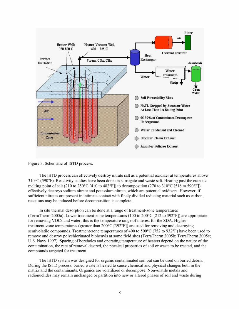
Figure 3. Schematic of ISTD process.
The ISTD process can effectively destroy nitrate salt as a potential oxidizer at temperatures above
310 C (590 F). Reactivity studies have been done on surrogate and waste salt. Heating past the eutectic
melting point of salt (210 to 250 C [410 to 482 F]) to decomposition (270 to 310 C [518 to 590 F])
effectively destroys sodium nitrate and potassium nitrate, which are potential oxidizers. However, if
sufficient nitrates are present in intimate contact with finely divided reducing material such as carbon,
reactions may be induced before decomposition is complete.
In situ thermal desorption can be done at a range of treatment-zone temperatures
(TerraTherm 2005a). Lower treatment-zone temperatures (100 to 200 C [212 to 392 F]) are appropriate
for removing VOCs and water; this is the temperature range of interest for the SDA. Higher
treatment-zone temperatures (greater than 200 C [392 F]) are used for removing and destroying
semivolatile compounds. Treatment-zone temperatures of 400 to 500 C (752 to 932 F) have been used to
remove and destroy polychlorinated biphenyls at some field sites (TerraTherm 2005b; TerraTherm 2005c;
U.S. Navy 1997). Spacing of boreholes and operating temperature of heaters depend on the nature of the
contamination, the rate of removal desired, the physical properties of soil or waste to be treated, and the
compounds targeted for treatment.
The ISTD system was designed for organic contaminated soil but can be used on buried debris.
During the ISTD process, buried waste is heated to cause chemical and physical changes both in the
matrix and the contaminants. Organics are volatilized or decompose. Nonvolatile metals and
radionuclides may remain unchanged or partition into new or altered phases of soil and waste during
9
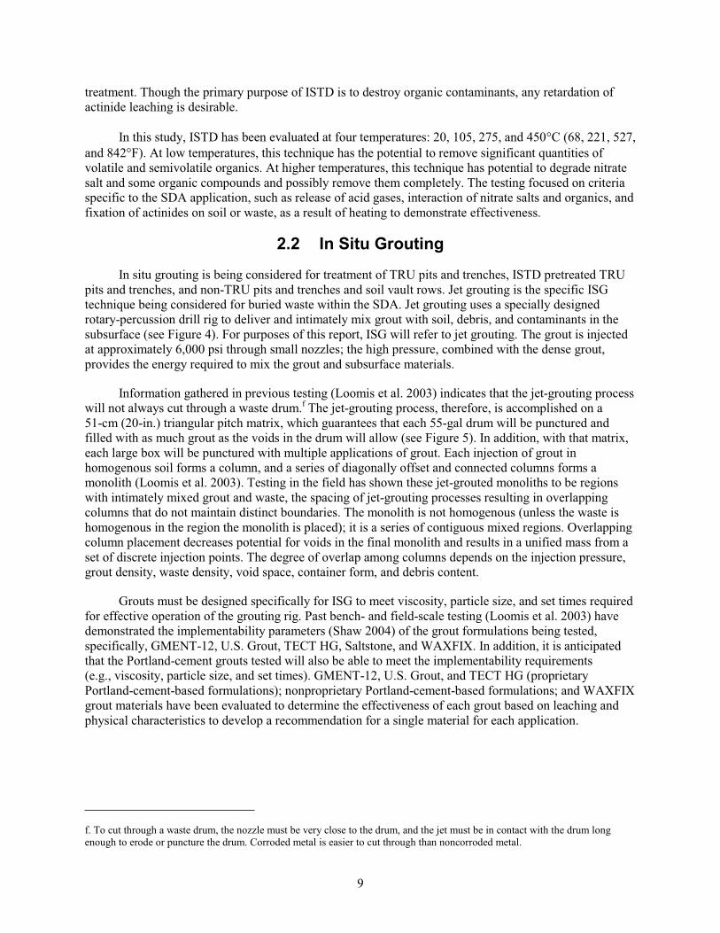
treatment. Though the primary purpose of ISTD is to destroy organic contaminants, any retardation of
actinide leaching is desirable.
In this study, ISTD has been evaluated at four temperatures: 20, 105, 275, and 450 C (68, 221, 527,
and 842 F). At low temperatures, this technique has the potential to remove significant quantities of
volatile and semivolatile organics. At higher temperatures, this technique has potential to degrade nitrate
salt and some organic compounds and possibly remove them completely. The testing focused on criteria
specific to the SDA application, such as release of acid gases, interaction of nitrate salts and organics, and
fixation of actinides on soil or waste, as a result of heating to demonstrate effectiveness.
2.2 In Situ Grouting
In situ grouting is being considered for treatment of TRU pits and trenches, ISTD pretreated TRU
pits and trenches, and non-TRU pits and trenches and soil vault rows. Jet grouting is the specific ISG
technique being considered for buried waste within the SDA. Jet grouting uses a specially designed
rotary-percussion drill rig to deliver and intimately mix grout with soil, debris, and contaminants in the
subsurface (see Figure 4). For purposes of this report, ISG will refer to jet grouting. The grout is injected
at approximately 6,000 psi through small nozzles; the high pressure, combined with the dense grout,
provides the energy required to mix the grout and subsurface materials.
Information gathered in previous testing (Loomis et al. 2003) indicates that the jet-grouting process
will not always cut through a waste drum.f The jet-grouting process, therefore, is accomplished on a
51-cm (20-in.) triangular pitch matrix, which guarantees that each 55-gal drum will be punctured and
filled with as much grout as the voids in the drum will allow (see Figure 5). In addition, with that matrix,
each large box will be punctured with multiple applications of grout. Each injection of grout in
homogenous soil forms a column, and a series of diagonally offset and connected columns forms a
monolith (Loomis et al. 2003). Testing in the field has shown these jet-grouted monoliths to be regions
with intimately mixed grout and waste, the spacing of jet-grouting processes resulting in overlapping
columns that do not maintain distinct boundaries. The monolith is not homogenous (unless the waste is
homogenous in the region the monolith is placed); it is a series of contiguous mixed regions. Overlapping
column placement decreases potential for voids in the final monolith and results in a unified mass from a
set of discrete injection points. The degree of overlap among columns depends on the injection pressure,
grout density, waste density, void space, container form, and debris content.
Grouts must be designed specifically for ISG to meet viscosity, particle size, and set times required
for effective operation of the grouting rig. Past bench- and field-scale testing (Loomis et al. 2003) have
demonstrated the implementability parameters (Shaw 2004) of the grout formulations being tested,
specifically, GMENT-12, U.S. Grout, TECT HG, Saltstone, and WAXFIX. In addition, it is anticipated
that the Portland-cement grouts tested will also be able to meet the implementability requirements
(e.g., viscosity, particle size, and set times). GMENT-12, U.S. Grout, and TECT HG (proprietary
Portland-cement-based formulations); nonproprietary Portland-cement-based formulations; and WAXFIX
grout materials have been evaluated to determine the effectiveness of each grout based on leaching and
physical characteristics to develop a recommendation for a single material for each application.
f. To cut through a waste drum, the nozzle must be very close to the drum, and the jet must be in contact with the drum long
enough to erode or puncture the drum. Corroded metal is easier to cut through than noncorroded metal.
10
Drill master
Drill probe
Figure 4. Preconceptual schematic of the overall process of in situ jet grouting.
11
Q-1
Q-4Q-3
Q-2
Combustible
Inorganic
NitrateM
Sack
Combustible
Inorganic
Organic
Combustible
Combustible
OrganicM
InorganicCombustible
Sack
Inorganic
Combustible
Inorganic
Combustible
Layer 1 Long-Term Disposal
SackCombustible
4 X 4 X 8-ft Box
4 X 4 X 8-ft Box
1
2 3
4
8
6
7
5
GC00 0211 1
Figure 5. Example of 20-inch, triangular-pitch, jet-grouting pattern.
2.3 Ex Situ Grouting
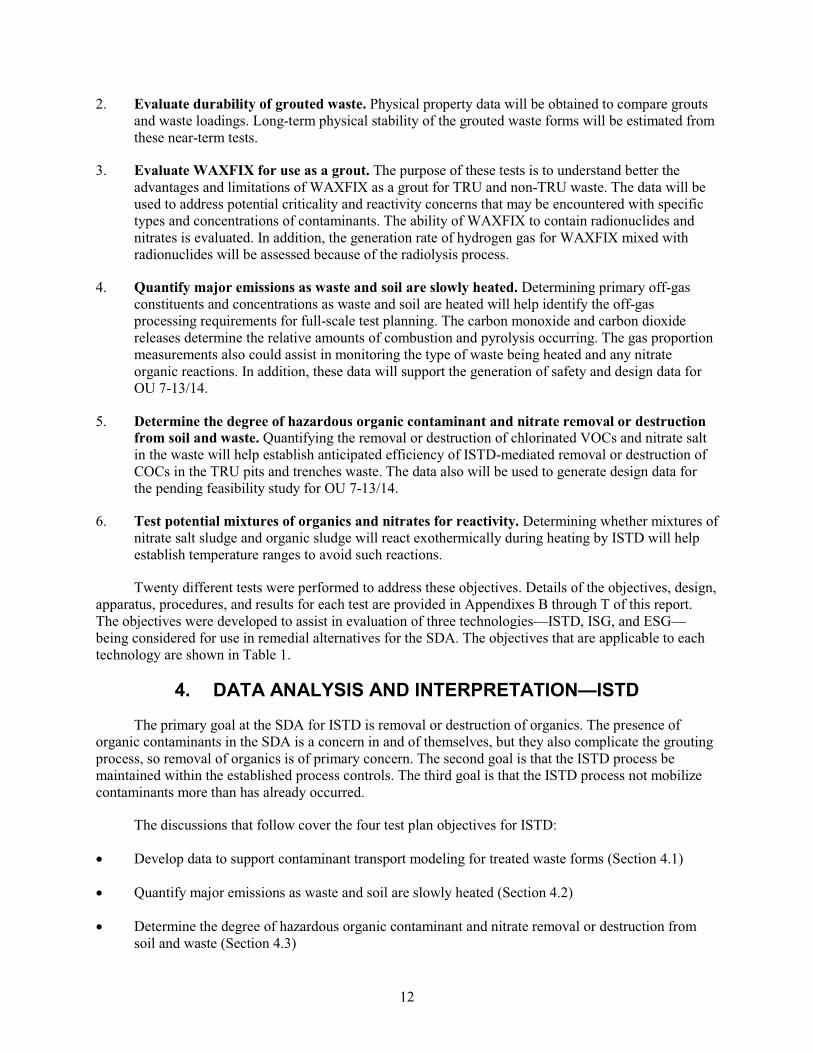
Ex situ grouting (solidification) is being considered for treatment of the Pad A salt waste. Ex situ
grouting includes selection of an appropriate grout and an approach to transfer the waste from Pad A to a
mixing system where containers could be opened, waste contents mixed with grout, and grout-waste
mixture placed in containers for disposal. Three candidate groutsg have been identified for testing:
Polysiloxane, Saltstone, and WAXFIX.
3. TESTING
The tests in this report address six main objectives from Yancey et al. (2003):
1. Develop data to support contaminant transport modeling for treated waste forms. Data
obtained from these tests will be used in modeling migration of contaminants in the final waste
form after ISG or ESG. In addition, these data will be used to determine changes in leachability of
actinides from the waste and surrounding soil following ISTD heating. These data will support
modeling to estimate the release rate of contaminants from the treated waste and compare it to the
predicted release rate from untreated waste. The test results also will support risk assessment, the
risk model, and evaluation of residual risk for the proposed alternatives for the feasibility study for
OU 7-13/14.
g. Dimethyl Polysiloxane, marketed by Technology Visions Group, uses a polymer encapsulation technology (Loomis, Miller,
and Prewett 1997) shown to successfully encapsulate surrogate salt materials. Saltstone grout, developed by Savannah River Site,
has been developed for salt encapsulation. WAXFIX also is considered in the in situ portion of Yancey et al. (2003).
12
2. Evaluate durability of grouted waste. Physical property data will be obtained to compare grouts
and waste loadings. Long-term physical stability of the grouted waste forms will be estimated from
these near-term tests.
3. Evaluate WAXFIX for use as a grout. The purpose of these tests is to understand better the
advantages and limitations of WAXFIX as a grout for TRU and non-TRU waste. The data will be
used to address potential criticality and reactivity concerns that may be encountered with specific
types and concentrations of contaminants. The ability of WAXFIX to contain radionuclides and
nitrates is evaluated. In addition, the generation rate of hydrogen gas for WAXFIX mixed with
radionuclides will be assessed because of the radiolysis process.
4. Quantify major emissions as waste and soil are slowly heated. Determining primary off-gas
constituents and concentrations as waste and soil are heated will help identify the off-gas
processing requirements for full-scale test planning. The carbon monoxide and carbon dioxide
releases determine the relative amounts of combustion and pyrolysis occurring. The gas proportion
measurements also could assist in monitoring the type of waste being heated and any nitrate
organic reactions. In addition, these data will support the generation of safety and design data for
OU 7-13/14.
5. Determine the degree of hazardous organic contaminant and nitrate removal or destruction
from soil and waste. Quantifying the removal or destruction of chlorinated VOCs and nitrate salt
in the waste will help establish anticipated efficiency of ISTD-mediated removal or destruction of
COCs in the TRU pits and trenches waste. The data also will be used to generate design data for
the pending feasibility study for OU 7-13/14.
6. Test potential mixtures of organics and nitrates for reactivity. Determining whether mixtures of
nitrate salt sludge and organic sludge will react exothermically during heating by ISTD will help
establish temperature ranges to avoid such reactions.
Twenty different tests were performed to address these objectives. Details of the objectives, design,
apparatus, procedures, and results for each test are provided in Appendixes B through T of this report.
The objectives were developed to assist in evaluation of three technologies—ISTD, ISG, and ESG—
being considered for use in remedial alternatives for the SDA. The objectives that are applicable to each
technology are shown in Table 1.
4. DATA ANALYSIS AND INTERPRETATION—ISTD
The primary goal at the SDA for ISTD is removal or destruction of organics. The presence of
organic contaminants in the SDA is a concern in and of themselves, but they also complicate the grouting
process, so removal of organics is of primary concern. The second goal is that the ISTD process be
maintained within the established process controls. The third goal is that the ISTD process not mobilize
contaminants more than has already occurred.
The discussions that follow cover the four test plan objectives for ISTD:
Develop data to support contaminant transport modeling for treated waste forms (Section 4.1)
Quantify major emissions as waste and soil are slowly heated (Section 4.2)
Determine the degree of hazardous organic contaminant and nitrate removal or destruction from
soil and waste (Section 4.3)
13
Test potential mixtures of organics and nitrates for reactivity (Section 4.4).
This testing includes retrieved waste and surrogates, depending on the type of testing conducted.
Table 1. Applicability of test objective to each technology.
Technologies
Objectives In Situ Thermal
Desorption In Situ Grouting Ex Situ Grouting
1. Develop data to support
contaminant transport modeling for
treated waste forms X X X
2. Evaluate durability of grouted
waste X X
3. Evaluate WAXFIX for use as a
grout X
4. Quantify major emissions as waste
and soil are slowly heated X
5. Determine the degree of hazardous
organic contaminant and nitrate
removal or destruction from soil and
waste
X
6. Test potential mixtures of organics
and nitrates for reactivity X
4.1 Develop Data to Support Contaminant Transport Modeling for Treated Waste Forms
Treatment of surrogate and waste by ISTD does not result in formation of consolidated material
(test monoliths) required for American Nuclear Society (ANS) leach testing. Another useful indicator of
contaminant mobility is the partition coefficient (Kd). Partition coefficients can be measured on
unconsolidated material, such as ISTD-treated material. Estimates of Kd for rare earths and radionuclides
were measured for ISTD-treated waste and surrogates. Evaluating the leachability of contaminants using
Kd data helps to answer the question of the effects of ISTD on leachability.
4.1.1 Partition Coefficients for ISTD-Treated Nonradioactive Surrogates
Three types of surrogates expected to contain high amounts of TRU contaminants (organic sludge
surrogate, inorganic sludge surrogate, and soil) were leach tested. The recipes for surrogates are included
in Appendix A. Soil used in testing was from the RWMC area (where waste and soil reside) of the INL
Site; it was dry and was sieved for uniformity.
Each of the surrogates was spiked with one or several of four rare-earth elements to simulate
radionuclides. Four rare-earth elements were used in testing: terbium, lanthanum, cerium, and
neodymium.
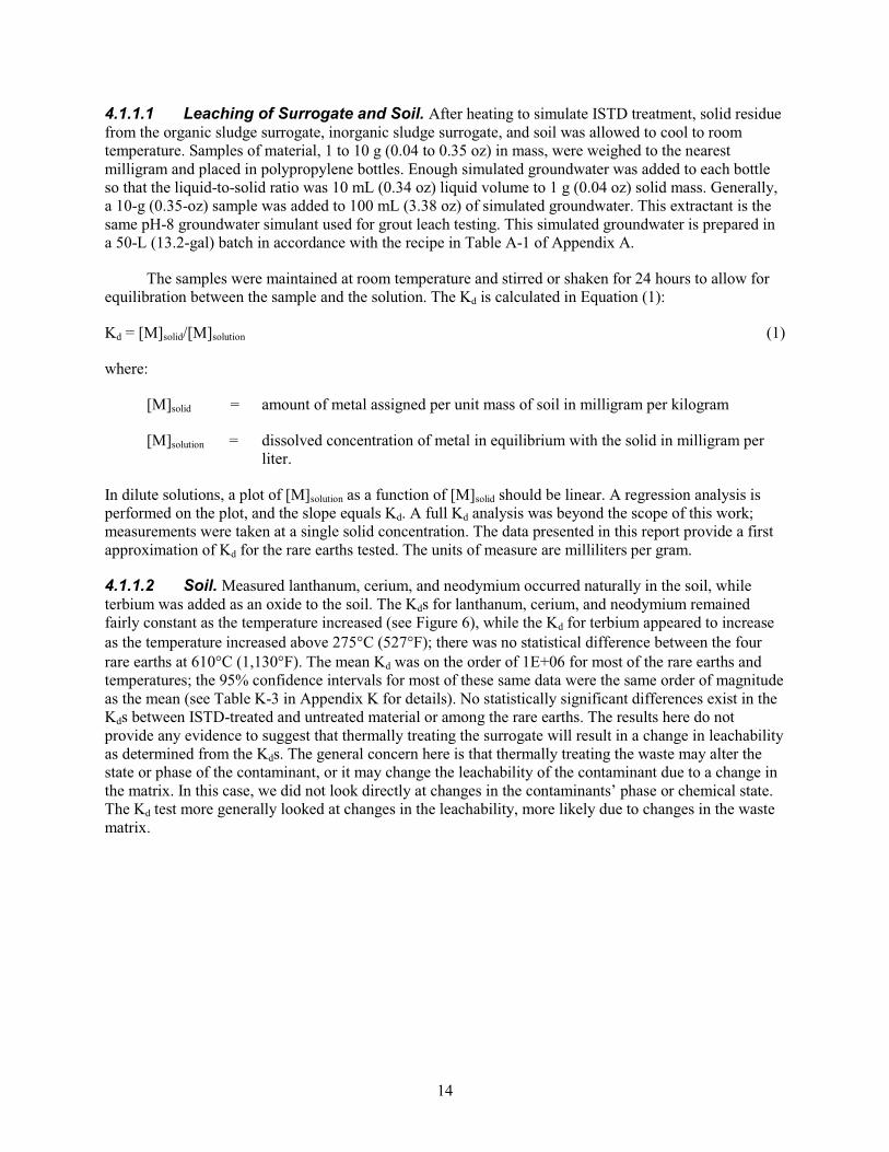
14
4.1.1.1 Leaching of Surrogate and Soil. After heating to simulate ISTD treatment, solid residue
from the organic sludge surrogate, inorganic sludge surrogate, and soil was allowed to cool to room
temperature. Samples of material, 1 to 10 g (0.04 to 0.35 oz) in mass, were weighed to the nearest
milligram and placed in polypropylene bottles. Enough simulated groundwater was added to each bottle
so that the liquid-to-solid ratio was 10 mL (0.34 oz) liquid volume to 1 g (0.04 oz) solid mass. Generally,
a 10-g (0.35-oz) sample was added to 100 mL (3.38 oz) of simulated groundwater. This extractant is the
same pH-8 groundwater simulant used for grout leach testing. This simulated groundwater is prepared in
a 50-L (13.2-gal) batch in accordance with the recipe in Table A-1 of Appendix A.
The samples were maintained at room temperature and stirred or shaken for 24 hours to allow for
equilibration between the sample and the solution. The Kd is calculated in Equation (1):
Kd = [M]solid/[M]solution (1)
where:
[M]solid = amount of metal assigned per unit mass of soil in milligram per kilogram
[M]solution = dissolved concentration of metal in equilibrium with the solid in milligram per
liter.
In dilute solutions, a plot of [M]solution as a function of [M]solid should be linear. A regression analysis is
performed on the plot, and the slope equals Kd. A full Kd analysis was beyond the scope of this work;
measurements were taken at a single solid concentration. The data presented in this report provide a first
approximation of Kd for the rare earths tested. The units of measure are milliliters per gram.
4.1.1.2 Soil. Measured lanthanum, cerium, and neodymium occurred naturally in the soil, while
terbium was added as an oxide to the soil. The Kds for lanthanum, cerium, and neodymium remained
fairly constant as the temperature increased (see Figure 6), while the Kd for terbium appeared to increase
as the temperature increased above 275 C (527 F); there was no statistical difference between the four
rare earths at 610 C (1,130 F). The mean Kd was on the order of 1E+06 for most of the rare earths and
temperatures; the 95% confidence intervals for most of these same data were the same order of magnitude
as the mean (see Table K-3 in Appendix K for details). No statistically significant differences exist in the
Kds between ISTD-treated and untreated material or among the rare earths. The results here do not
provide any evidence to suggest that thermally treating the surrogate will result in a change in leachability
as determined from the Kds. The general concern here is that thermally treating the waste may alter the
state or phase of the contaminant, or it may change the leachability of the contaminant due to a change in
the matrix. In this case, we did not look directly at changes in the contaminants’ phase or chemical state.
The Kd test more generally looked at changes in the leachability, more likely due to changes in the waste
matrix.
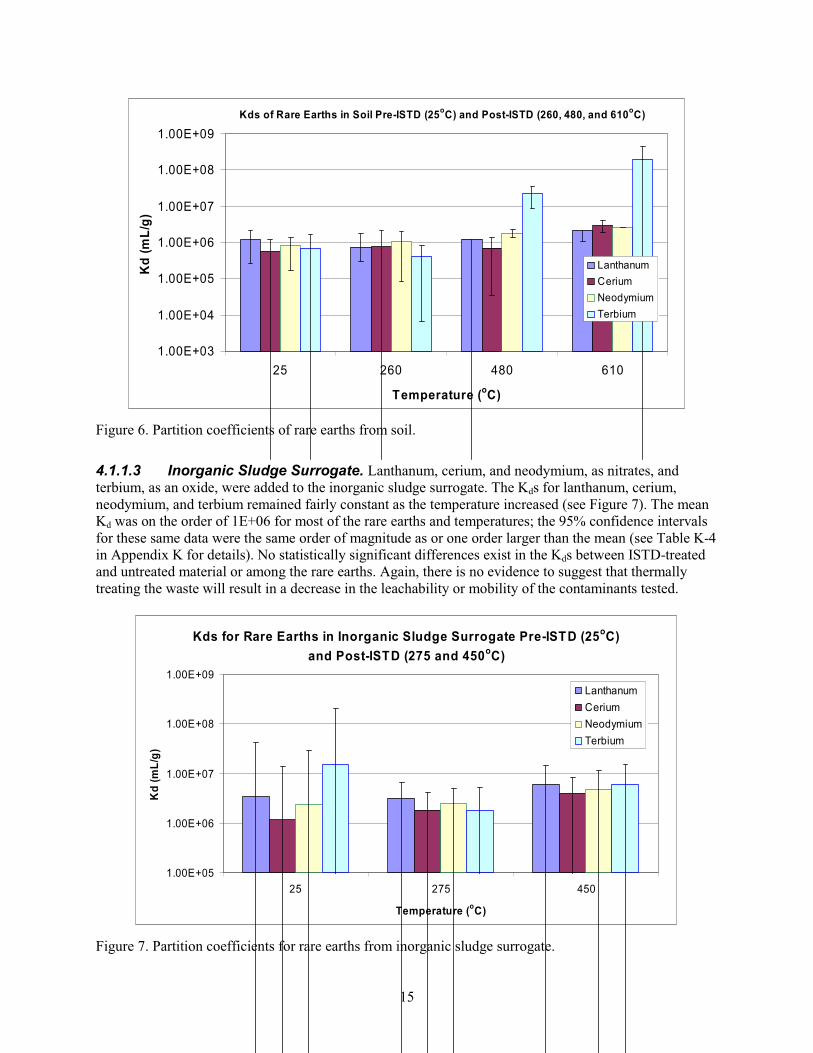
15
Kds of Rare Earths in Soil Pre-ISTD (25oC) and Post-ISTD (260, 480, and 610
oC)
1.00E+03
1.00E+04
1.00E+05
1.00E+06
1.00E+07
1.00E+08
1.00E+09
25 260 480 610
Temperature (oC)
Kd
(m
L/g
)
Lanthanum
Cerium
Neodymium
Terbium
Figure 6. Partition coefficients of rare earths from soil.
4.1.1.3 Inorganic Sludge Surrogate. Lanthanum, cerium, and neodymium, as nitrates, and
terbium, as an oxide, were added to the inorganic sludge surrogate. The Kds for lanthanum, cerium,
neodymium, and terbium remained fairly constant as the temperature increased (see Figure 7). The mean
Kd was on the order of 1E+06 for most of the rare earths and temperatures; the 95% confidence intervals
for these same data were the same order of magnitude as or one order larger than the mean (see Table K-4
in Appendix K for details). No statistically significant differences exist in the Kds between ISTD-treated
and untreated material or among the rare earths. Again, there is no evidence to suggest that thermally
treating the waste will result in a decrease in the leachability or mobility of the contaminants tested.
Kds for Rare Earths in Inorganic Sludge Surrogate Pre-ISTD (25oC)
and Post-ISTD (275 and 450oC)
1.00E+05
1.00E+06
1.00E+07
1.00E+08
1.00E+09
25 275 450
Temperature (oC)
Kd
(m
L/g
)
Lanthanum
Cerium
Neodymium
Terbium
Figure 7. Partition coefficients for rare earths from inorganic sludge surrogate.

16
4.1.1.4 Organic Sludge Surrogate. Lanthium, cerium, and neodymium, as nitrates, and terbium,
as an oxide, were added to the organic sludge surrogate. The Kds for lanthanum, cerium, neodymium, and
terbium appear to increase as the temperature increases (see Figure 8; error bars are not present for the
25 and 105 C (77 and 221 F) data because no replicates were taken for these points); however the 95%
confidence interval for each of the rare earths at 650 C (1,202 F) exceeds the value of the mean. The
mean Kds spanned seven orders of magnitude: 1E+02 to 1E+09. The values of the 95% confidence
intervals for these same data were the same order of magnitude or larger than the mean (see Table K-5 in
Appendix K for details). Because of the high degree of variance, no statistically significant differences
could be determined in the Kds between ISTD-treated and untreated material, among rare earths or
temperatures.
Kds of Rare Earths from Organic Sludge Surrogate Pre-ISTD (25oC)
and Post-ISTD (105, 275, 450, and 650oC)
1.00E+02
1.00E+03
1.00E+04
1.00E+05
1.00E+06
1.00E+07
1.00E+08
1.00E+09
1.00E+10
1.00E+11
25°C 105°C 275°C 450°C 650°C
Temperature (oC)
Kd
(m
L/g
)
Lanthanum
Cerium
Neodymium
Terbium
Figure 8. Partition coefficients for rare earths from organic sludge surrogate.
4.1.2 Partition Coefficients for ISTD-Treated Transuranic Surrogates and Waste
For soil from the INL Site spiked with radionuclides (americium, uranium, plutonium, and
neptunium) and then processed by ISTD, the Kds for americium, uranium, plutonium, and neptunium did
not change significantly (compared to pre-ISTD) with temperature, except for neptunium at 450 C
(842 F), where the Kd increased (see Figure 9). When radionuclides were tested, there was no benefit
from the standpoint of decreasing leachability when the waste was thermally treated. The only exception
is with americium, where there was an increased Kd for ISTD treatment at 450 C (842 F) compared to no
ISTD. The results were statistically different at the 95% confidence interval.
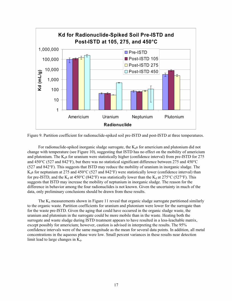
17
Kd for Radionuclide-Spiked Soil Pre-ISTD and
Post-ISTD at 105, 275, and 450°C
1
10
100
1,000
10,000
100,000
1,000,000
Americium Uranium Neptunium Plutonium
Radionuclide
Kd
(m
L/g
)
Pre-ISTD
Post-ISTD 105
Post-ISTD 275
Post-ISTD 450
Figure 9. Partition coefficient for radionuclide-spiked soil pre-ISTD and post-ISTD at three temperatures.
For radionuclide-spiked inorganic sludge surrogate, the Kds for americium and plutonium did not
change with temperature (see Figure 10), suggesting that ISTD has no effect on the mobility of americium
and plutonium. The Kds for uranium were statistically higher (confidence interval) from pre-ISTD for 275
and 450 C (527 and 842 F), but there was no statistical significant difference between 275 and 450 C
(527 and 842 F). This suggests that ISTD may reduce the mobility of uranium in inorganic sludge. The
Kds for neptunium at 275 and 450 C (527 and 842 F) were statistically lower (confidence interval) than
for pre-ISTD, and the Kd at 450 C (842 F) was statistically lower than the Kd at 275 C (527 F). This
suggests that ISTD may increase the mobility of neptunium in inorganic sludge. The reason for the
difference in behavior among the four radionuclides is not known. Given the uncertainty in much of the
data, only preliminary conclusions should be drawn from these results.
The Kd measurements shown in Figure 11 reveal that organic sludge surrogate partitioned similarly
to the organic waste. Partition coefficients for uranium and plutonium were lower for the surrogate than
for the waste pre-ISTD. Given the aging that could have occurred in the organic sludge waste, the
uranium and plutonium in the surrogate could be more mobile than in the waste. Heating both the
surrogate and waste sludge during ISTD treatment appears to have resulted in a less-leachable matrix,
except possibly for americium; however, caution is advised in interpreting the results. The 95%
confidence intervals were of the same magnitude as the mean for several data points. In addition, all metal
concentrations in the aqueous phase were low. Small percent variances in these results near detection
limit lead to large changes in Kd.
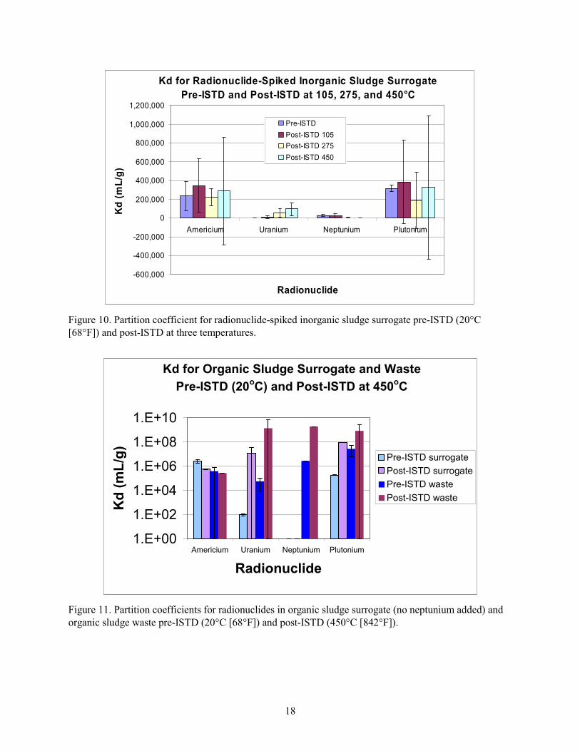
18
Kd for Radionuclide-Spiked Inorganic Sludge Surrogate
Pre-ISTD and Post-ISTD at 105, 275, and 450°C
-600,000
-400,000
-200,000
0
200,000
400,000
600,000
800,000
1,000,000
1,200,000
Americium Uranium Neptunium Plutonium
Radionuclide
Kd
(m
L/g
)Pre-ISTD
Post-ISTD 105
Post-ISTD 275
Post-ISTD 450
Figure 10. Partition coefficient for radionuclide-spiked inorganic sludge surrogate pre-ISTD (20 C
[68 F]) and post-ISTD at three temperatures.
Kd for Organic Sludge Surrogate and Waste
Pre-ISTD (20oC) and Post-ISTD at 450
oC
1.E+00
1.E+02
1.E+04
1.E+06
1.E+08
1.E+10
Americium Uranium Neptunium Plutonium
Radionuclide
Kd
(m
L/g
)
Pre-ISTD surrogate
Post-ISTD surrogate
Pre-ISTD waste
Post-ISTD waste
Figure 11. Partition coefficients for radionuclides in organic sludge surrogate (no neptunium added) and
organic sludge waste pre-ISTD (20 C [68 F]) and post-ISTD (450 C [842 F]).

19
4.1.3 Conclusions for Contaminant Transport Modeling for ISTD
No clear pattern emerged from the Kd data for ISTD-treated surrogates and waste at the
temperatures studied. In soil, only the Kd for neptunium showed an increase (significant at 95%
confidence level) at an ISTD temperature of 450 C (842 F) compared to pre-ISTD. For inorganic sludge
surrogate, the Kds for uranium were higher (at 95% confidence level) than for pre-ISTD for 275 and
450 C (527 and 842 F), and the Kds for neptunium at 275 and 450 C (527 and 842 F) were statistically
lower (95% confidence level) than for pre-ISTD, meaning that the leachability of neptunium increased
following ISTD treatment. For the organic sludge surrogate and waste, ISTD treatment appears to have
resulted in a less-leachable matrix, except possibly for americium. Caution should be used in interpreting
these results; all metal concentrations in the aqueous phase were low, and small percent variances in these
results near detection limit lead to large changes in Kd.
One of the parameters tested for ISTD treated material was the ability of ISTD to reduce the
leachability of the radionuclide COCs from the specific matrices. The results from this study do not
provide evidence to show that this occurs. Only in the case of high-temperature ISTD of organic sludge
does ISTD appear to provide a benefit by reducing leachability of radionuclides with the exception of
americium. For soil from the INL Site and inorganic sludge, the leachability of the contaminant was
usually unaffected as a result of the ISTD treatment, even at high temperatures.
4.2 Quantify Major Emissions as Waste and Soil are Slowly Heated
Surrogates (with and without radionuclides) and waste were used for tests in this section, as noted.
The overall objective of this work was to better quantify the type of emissions that could be released
during ISTD. Section 4.2.1 covers the work completed by MSE on nonradioactive surrogates. The MSE
tests were larger drum-scale tests. Section 4.2.2 covers the ISTD of radioactive surrogate and waste
completed at the INL Site, and was performed on a smaller scale using surrogate and waste that was ISTD
treated. The second set of tests was used to confirm that the MSE drum-scale tests matched what would
occur using the radioactive waste and surrogate.
4.2.1 MSE Drum Tests
The MSE vacuum thermal desorption system consists of a carbon-steel chamber sized to
completely enclose a 55-gal test drum (see Appendix I for details of the equipment). For these tests, the
system was operated under a slight vacuum (10.2 to 12.7 cm [4 to 5 in.] of water). The slight vacuum
primarily was intended to simulate ISTD heating but also ensured that any gases released in the drum
during thermal desorption were drawn into the off-gas treatment system, preventing leakage into the work
area around the test bed.
To simulate airflow through soil into the slight vacuum of an ISTD heater assembly, air is metered
by a mass flow control valve into the bottom of the 55-gal test drum where the air can be dispersed
circumferentially around the drum by a distribution ring or injected at a point near the bottom of the
drum. Six thermocouples monitored the temperature of the drum contents during heating: two near the
center heater assembly, two halfway between the heater assembly and the drum wall, and two near the
drum wall. The thermocouples are identified by position as top or bottom, and inner, middle, or outer.
A shakedown and four surrogate tests were conducted: organic sludge surrogate (Drum 1), nitrate
salt surrogate (Drum 2), organic sludge surrogate with combustible debris surrogate (Drum 3), and
organic sludge surrogate with combustible debris and soil (Drum 4). All of the tests were conducted with
surrogate without radionuclides.
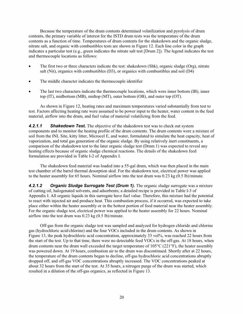
20
Because the temperature of the drum contents determined volatilization and pyrolysis of drum
contents, the primary variable of interest for the ISTD drum tests was the temperature of the drum
contents as a function of time. Temperatures of drum contents for the shakedown and the organic sludge,
nitrate salt, and organic with combustibles tests are shown in Figure 12. Each line color in the graph
indicates a particular test (e.g., green indicates the nitrate salt test [Drum 2]). The legend indicates the test
and thermocouple locations as follows:
The first two or three characters indicate the test: shakedown (Shk), organic sludge (Org), nitrate
salt (Nit), organics with combustibles (D3), or organics with combustibles and soil (D4)
The middle character indicates the thermocouple identifier
The last two characters indicate the thermocouple locations, which were inner bottom (IB), inner
top (IT), midbottom (MB), midtop (MT), outer bottom (OB), and outer top (OT).
As shown in Figure 12, heating rates and maximum temperatures varied substantially from test to
test. Factors affecting heating rate were assumed to be power input to the heater, water content in the feed
material, airflow into the drum, and fuel value of material volatilizing from the feed.
4.2.1.1 Shakedown Test. The objective of the shakedown test was to check out system
components and to monitor the heating profile of the drum contents. The drum contents were a mixture of
soil from the INL Site, kitty litter, Microcel E, and water, formulated to simulate the heat capacity, heat of
vaporization, and total gas generation of the organic sludge. By using relatively inert constituents, a
comparison of the shakedown test to the later organic sludge test (Drum 1) was expected to reveal any
heating effects because of organic sludge chemical reactions. The details of the shakedown feed
formulation are provided in Table I-2 of Appendix I.
The shakedown feed material was loaded into a 55-gal drum, which was then placed in the main
test chamber of the barrel thermal desorption skid. For the shakedown test, electrical power was applied
to the heater assembly for 65 hours. Nominal airflow into the test drum was 0.23 kg (0.5 lb)/minute.
4.2.1.2 Organic Sludge Surrogate Test (Drum 1). The organic sludge surrogate was a mixture
of cutting oil, halogenated solvents, and adsorbents; a detailed recipe is provided in Table I-3 of
Appendix I. All organic liquids in this surrogate have fuel value. Therefore, this mixture had the potential
to react with injected air and produce heat. This combustion process, if it occurred, was expected to take
place either within the heater assembly or in the hottest portion of feed material near the heater assembly.
For the organic sludge test, electrical power was applied to the heater assembly for 22 hours. Nominal
airflow into the test drum was 0.23 kg (0.5 lb)/minute.
Off-gas from the organic sludge test was sampled and analyzed for hydrogen chloride and chlorine
gas (hydrochloric acid/chlorine) and the four VOCs included in the drum contents. As shown in
Figure 13, the peak hydrochloric acid concentration, approximately 33 vol%, was reached 22 hours from
the start of the test. Up to that time, there were no detectable feed VOCs in the off-gas. At 18 hours, when
drum contents near the drum wall exceeded the target temperature of 105 C (221 F), the heater assembly
was powered down. At 19 hours, combustion air to the drum was discontinued. Shortly after at 22 hours,
the temperature of the drum contents began to decline, off-gas hydrochloric acid concentrations abruptly
dropped off, and off-gas VOC concentrations abruptly increased. The VOC concentrations peaked at
about 32 hours from the start of the test. At 35 hours, a nitrogen purge of the drum was started, which
resulted in a dilution of the off-gas organics, as reflected in Figure 13.
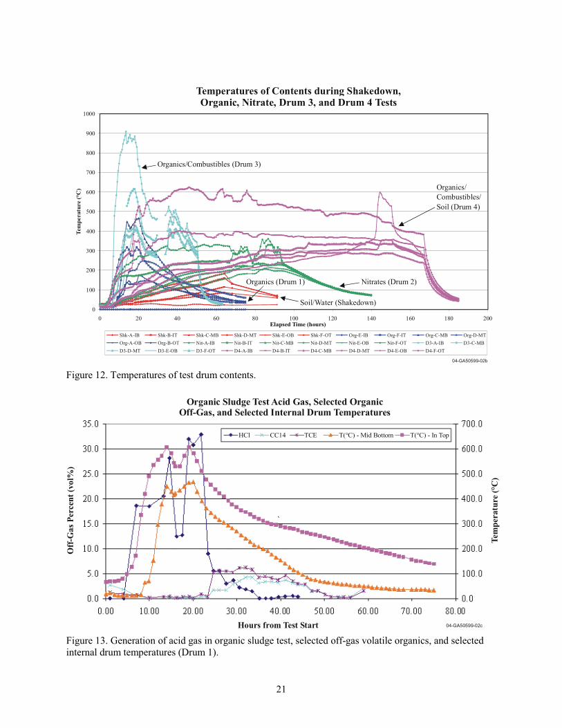
21
04-GA50599-02b
Temperatures of Contents during Shakedown, Organic, Nitrate, Drum 3, and Drum 4 Tests
0
100
200
300
400
500
600
700
800
900
1000
0 20 40 60 80 100 120 140 160 180 200Elapsed Time (hours)
Shk-A-IB Shk-B-IT Shk-C-MB Shk-D-MT Shk-E-OB Shk-F-OT Org-E-IB Org-F-IT Org-C-MB Org-D-MT
Org-A-OB Org-B-OT Nit-A-IB Nit-B-IT Nit-C-MB Nit-D-MT Nit-E-OB Nit-F-OT D3-A-IB D3-C-MB
D3-D-MT D3-E-OB D3-F-OT D4-A-IB D4-B-IT D4-C-MB D4-D-MT D4-E-OB D4-F-OT
Soil/Water (Shakedown)
Organics (Drum 1)
Organics/
Combustibles/
Soil (Drum 4)
Nitrates (Drum 2)
Organics/Combustibles (Drum 3)
Tem
pera
ture
(°C
)
Figure 12. Temperatures of test drum contents.
Organic Sludge Test Acid Gas, Selected OrganicOff-Gas, and Selected Internal Drum Temperatures
Hours from Test Start
Off
-Ga
s P
erce
nt
(vo
l%)
Tem
per
atu
re (
°C)
HCl CC14 TCE T(°C) - Mid Bottom T(°C) - In Top
04-GA50599-02c
Figure 13. Generation of acid gas in organic sludge test, selected off-gas volatile organics, and selected
internal drum temperatures (Drum 1).

22
The crossover of hydrochloric acid and VOC concentrations apparently was because of incomplete
combustion of VOCs volatilized from the feed material. While power was supplied to the heater, the
VOCs, which were the only source of chlorine, were evidently fully oxidized to hydrochloric acid, carbon
dioxide, and water. When the heater power was turned off, the VOCs continued to volatilize from the
drum; however, the presumed combustion zone near or within the heater assembly was apparently no
longer hot enough to oxidize the VOCs. A qualitative organic compound scan of an off-gas sample taken
during this cooling period showed numerous partially dechlorinated products of the feed organic VOCs,
further suggesting incomplete oxidation of organics after the heater power was turned off.
4.2.1.3 Nitrate Salt Surrogate Test (Drum 2). The nitrate salt surrogate was a mixture of
90 wt% nitrate salts, miscellaneous other salts, 1 wt% ethylenediaminetetraacetic acid (EDTA), and
0.5 wt% ceric oxide (added as a plutonium surrogate); details of the recipe are shown in Table I-4 in
Appendix I. (The as-mixed formula was normalized to a total of 100%.) For the nitrate salt test,
electrical power was applied to the heater assembly for 65 hours. Nominal airflow into the test drum was
0.23 kg (0.5 lb)/minute.
While the nitrate compounds are strong oxidizers, particularly when heated, the only combustible
compound in the mixture was EDTA (at 1 wt%), which provided only a trace of fuel for the nitrate
oxidizers. Accordingly, heating this mixture was expected to result in only minimal exothermic reactions.
As shown in Figure 12, the heating rate for the nitrate salt drum contents was slightly faster than for the
shakedown test and much slower than for the organic sludge surrogate test (Drum 1). For the nitrate salt
test, heater power was applied for approximately 65 hours, at which time the temperature of the drum
contents peaked at approximately 185 C (365 F). The off-gas was sampled and analyzed for the four
VOC compounds of the organic sludge surrogate and for hydrochloric acid/chlorine. As expected, since
the feed did not contain VOCs, VOCs were not detected in the off-gas. The feed material contained a
relatively minor source of chlorine (3 wt% sodium chloride); however, hydrochloric acid/chlorine also
was not detectable in the off-gas, most likely because the temperatures were not sufficient to decompose
sodium chloride.
4.2.1.4 Organic Sludge Surrogate with Combustible Debris Test Surrogate (Drum 3). A combustible debris surrogate consisting of 40 wt% cotton rags, 40 wt% paper towels, 10 wt%
polyethylene beads, 5 wt% polyvinyl chloride beads, and 5 wt% acrylonitrile-butadiene-styrenes plastic
beads was prepared for this test (for additional detail, see Table I-5 in Appendix I). The feed formulation
for this test consisted of 35 wt% organic sludge, 55 wt% combustible debris, and 10 wt% water. This
formulation was intended to simulate the contents of drums buried at the RWMC that contain cutting oil,
halogenated solvents, adsorbents, paper, cloth, and plastic scrap. For the organic sludge with combustible
debris test (Drum 3), electrical power was applied to the heater assembly for 50.1 hours. Nominal airflow
to the test drum was 0.23 kg (0.5 lb)/minute.
As shown in Figure 12, the peak temperature for the organic sludge with combustible debris drum
contents was 910 C (1,670 F), observed at 13.5 hours from the start of heating at the inner bottom
thermocouple. Peak temperatures and times for the middle and outer thermocouples were 617 C
(1,142.6 F) at 18 hours and 423 C (793.4 F) at 18.5 hours, respectively. Both the rate of temperature rise
and the peak temperatures were substantially greater than the tests for shakedown, organic sludge
(Drum 1), or nitrate salt (Drum 2). Similarly to the organic sludge test, the rapid rise in temperature
apparently was because of combustion of the drum contents.
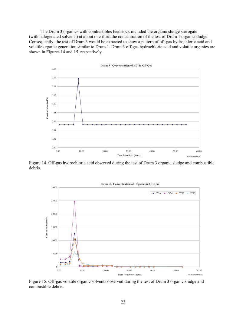
23
The Drum 3 organics with combustibles feedstock included the organic sludge surrogate
(with halogenated solvents) at about one-third the concentration of the test of Drum 1 organic sludge.
Consequently, the test of Drum 3 would be expected to show a pattern of off-gas hydrochloric acid and
volatile organic generation similar to Drum 1. Drum 3 off-gas hydrochloric acid and volatile organics are
shown in Figures 14 and 15, respectively.
Drum 3 - Concentration of HCl in Off-Gas
0.00
0.02
0.04
0.06
0.08
0.10
0.12
0.14
0.16
0.18
0.00 10.00 20.00 30.00 40.00 50.00 60.00
Time from Start (hours)04-GA50599-02d
Co
ncen
tra
tio
n (
vo
l%)
Figure 14. Off-gas hydrochloric acid observed during the test of Drum 3 organic sludge and combustible
debris.
Drum 3 - Concentration of Organics in Off-Gas
0
5000
10000
15000
20000
25000
30000
0.00 10.00 20.00 30.00 40.00 50.00 60.00
Time from Start (hours)
TCA CCl4 TCE PCE
04-GA50599-02e
Co
ncen
tra
tio
n (
vo
l%)
Figure 15. Off-gas volatile organic solvents observed during the test of Drum 3 organic sludge and
combustible debris.
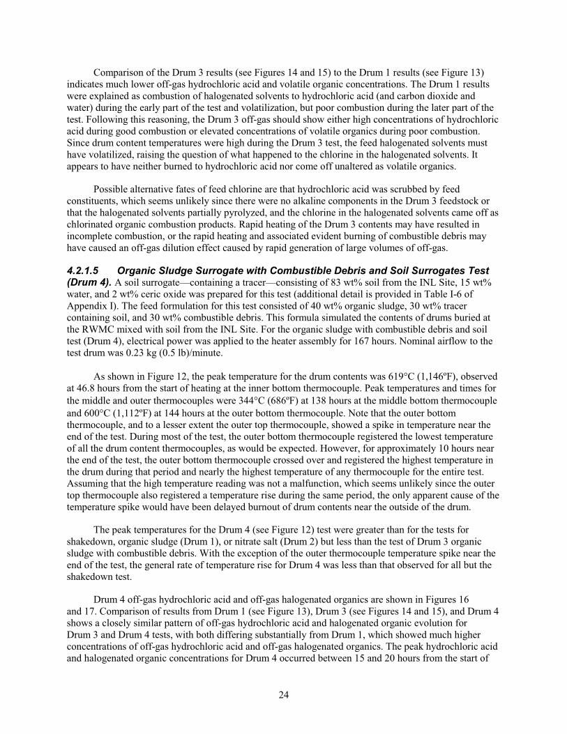
24
Comparison of the Drum 3 results (see Figures 14 and 15) to the Drum 1 results (see Figure 13)
indicates much lower off-gas hydrochloric acid and volatile organic concentrations. The Drum 1 results
were explained as combustion of halogenated solvents to hydrochloric acid (and carbon dioxide and
water) during the early part of the test and volatilization, but poor combustion during the later part of the
test. Following this reasoning, the Drum 3 off-gas should show either high concentrations of hydrochloric
acid during good combustion or elevated concentrations of volatile organics during poor combustion.
Since drum content temperatures were high during the Drum 3 test, the feed halogenated solvents must
have volatilized, raising the question of what happened to the chlorine in the halogenated solvents. It
appears to have neither burned to hydrochloric acid nor come off unaltered as volatile organics.
Possible alternative fates of feed chlorine are that hydrochloric acid was scrubbed by feed
constituents, which seems unlikely since there were no alkaline components in the Drum 3 feedstock or
that the halogenated solvents partially pyrolyzed, and the chlorine in the halogenated solvents came off as
chlorinated organic combustion products. Rapid heating of the Drum 3 contents may have resulted in
incomplete combustion, or the rapid heating and associated evident burning of combustible debris may
have caused an off-gas dilution effect caused by rapid generation of large volumes of off-gas.
4.2.1.5 Organic Sludge Surrogate with Combustible Debris and Soil Surrogates Test (Drum 4). A soil surrogate—containing a tracer—consisting of 83 wt% soil from the INL Site, 15 wt%
water, and 2 wt% ceric oxide was prepared for this test (additional detail is provided in Table I-6 of
Appendix I). The feed formulation for this test consisted of 40 wt% organic sludge, 30 wt% tracer
containing soil, and 30 wt% combustible debris. This formula simulated the contents of drums buried at
the RWMC mixed with soil from the INL Site. For the organic sludge with combustible debris and soil
test (Drum 4), electrical power was applied to the heater assembly for 167 hours. Nominal airflow to the
test drum was 0.23 kg (0.5 lb)/minute.
As shown in Figure 12, the peak temperature for the drum contents was 619 C (1,146ºF), observed
at 46.8 hours from the start of heating at the inner bottom thermocouple. Peak temperatures and times for
the middle and outer thermocouples were 344 C (686ºF) at 138 hours at the middle bottom thermocouple
and 600 C (1,112ºF) at 144 hours at the outer bottom thermocouple. Note that the outer bottom
thermocouple, and to a lesser extent the outer top thermocouple, showed a spike in temperature near the
end of the test. During most of the test, the outer bottom thermocouple registered the lowest temperature
of all the drum content thermocouples, as would be expected. However, for approximately 10 hours near
the end of the test, the outer bottom thermocouple crossed over and registered the highest temperature in
the drum during that period and nearly the highest temperature of any thermocouple for the entire test.
Assuming that the high temperature reading was not a malfunction, which seems unlikely since the outer
top thermocouple also registered a temperature rise during the same period, the only apparent cause of the
temperature spike would have been delayed burnout of drum contents near the outside of the drum.
The peak temperatures for the Drum 4 (see Figure 12) test were greater than for the tests for
shakedown, organic sludge (Drum 1), or nitrate salt (Drum 2) but less than the test of Drum 3 organic
sludge with combustible debris. With the exception of the outer thermocouple temperature spike near the
end of the test, the general rate of temperature rise for Drum 4 was less than that observed for all but the
shakedown test.
Drum 4 off-gas hydrochloric acid and off-gas halogenated organics are shown in Figures 16
and 17. Comparison of results from Drum 1 (see Figure 13), Drum 3 (see Figures 14 and 15), and Drum 4
shows a closely similar pattern of off-gas hydrochloric acid and halogenated organic evolution for
Drum 3 and Drum 4 tests, with both differing substantially from Drum 1, which showed much higher
concentrations of off-gas hydrochloric acid and off-gas halogenated organics. The peak hydrochloric acid
and halogenated organic concentrations for Drum 4 occurred between 15 and 20 hours from the start of
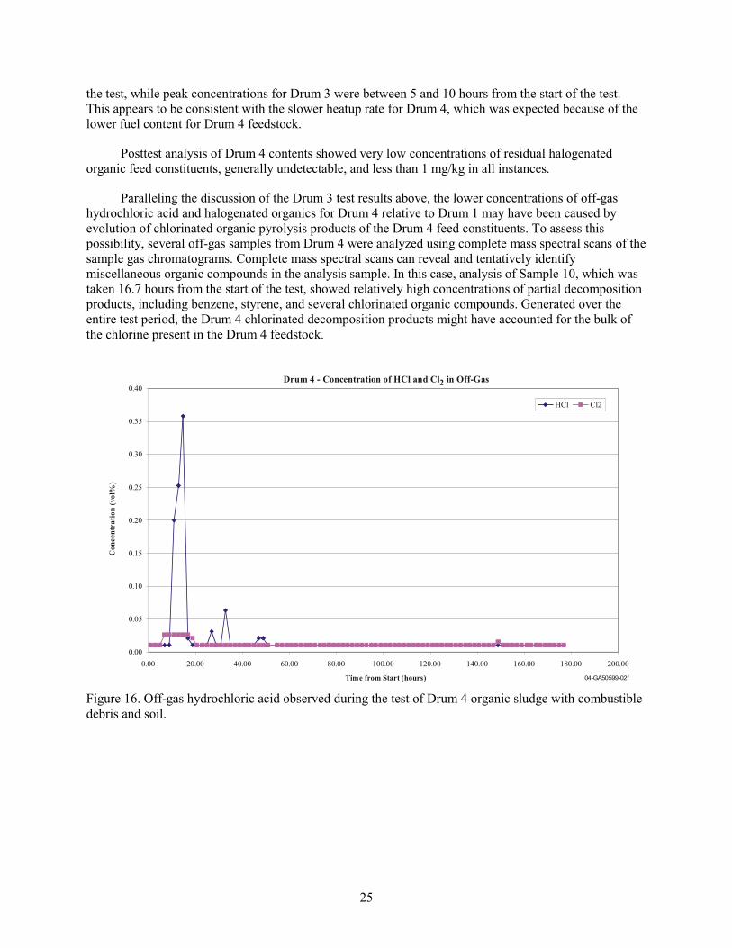
25
the test, while peak concentrations for Drum 3 were between 5 and 10 hours from the start of the test.
This appears to be consistent with the slower heatup rate for Drum 4, which was expected because of the
lower fuel content for Drum 4 feedstock.
Posttest analysis of Drum 4 contents showed very low concentrations of residual halogenated
organic feed constituents, generally undetectable, and less than 1 mg/kg in all instances.
Paralleling the discussion of the Drum 3 test results above, the lower concentrations of off-gas
hydrochloric acid and halogenated organics for Drum 4 relative to Drum 1 may have been caused by
evolution of chlorinated organic pyrolysis products of the Drum 4 feed constituents. To assess this
possibility, several off-gas samples from Drum 4 were analyzed using complete mass spectral scans of the
sample gas chromatograms. Complete mass spectral scans can reveal and tentatively identify
miscellaneous organic compounds in the analysis sample. In this case, analysis of Sample 10, which was
taken 16.7 hours from the start of the test, showed relatively high concentrations of partial decomposition
products, including benzene, styrene, and several chlorinated organic compounds. Generated over the
entire test period, the Drum 4 chlorinated decomposition products might have accounted for the bulk of
the chlorine present in the Drum 4 feedstock.
Drum 4 - Concentration of HCl and Cl in Off-Gas2
0.00
0.05
0.10
0.15
0.20
0.25
0.30
0.35
0.40
0.00 20.00 40.00 60.00 80.00 100.00 120.00 140.00 160.00 180.00 200.00
Time from Start (hours)
HCl Cl2
Co
ncen
tra
tio
n (
vo
l%)
04-GA50599-02f
Figure 16. Off-gas hydrochloric acid observed during the test of Drum 4 organic sludge with combustible
debris and soil.
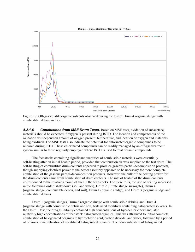
26
Drum 4 - Concentration of Organics in Off-Gas
0
5000
10000
15000
20000
25000
0.00 20.00 40.00 60.00 80.00 100.00 120.00 140.00 160.00 180.00
Time from Start (hours)
TCA CCl4 TCE PCE
Co
nce
ntr
ati
on
(vo
l%)
04-GA50599-02g
Figure 17. Off-gas volatile organic solvents observed during the test of Drum 4 organic sludge with
combustible debris and soil.
4.2.1.6 Conclusions from MSE Drum Tests. Based on MSE tests, oxidation of subsurface
materials should be expected if oxygen is present during ISTD. The location and completeness of the
oxidation will depend on amount of oxygen present, temperature, and location of oxygen and materials
being oxidized. The MSE tests also indicate the potential for chlorinated organic compounds to be
released during ISTD. These chlorinated compounds can be readily managed by an off-gas treatment
system similar to those regularly employed where ISTD is used to treat organic compounds.
The feedstocks containing significant quantities of combustible materials were essentially
self-heating after an initial heatup period, provided that combustion air was supplied to the test drum. The
self-heating of combustible drum contents appeared to produce gaseous partial-decomposition products,
though supplying electrical power to the heater assembly appeared to be necessary for more complete
combustion of the gaseous partial-decomposition products. However, the bulk of the heating power for
the drum contents came from combustion of drum contents. The rate of heatup of the drum contents
corresponded to the relative amount of fuel in the feedstocks. For these tests, the rate of heating increased
in the following order: shakedown (soil and water), Drum 2 (nitrate sludge surrogate), Drum 4
(organic sludge, combustible debris, and soil), Drum 1 (organic sludge), and Drum 3 (organic sludge and
combustible debris).
Drum 1 (organic sludge), Drum 3 (organic sludge with combustible debris), and Drum 4
(organic sludge with combustible debris and soil) tests used feedstock containing halogenated solvents. In
the Drum 1 test, the off-gas initially contained high concentrations of hydrochloric acid and later
relatively high concentrations of feedstock halogenated organics. This was attributed to initial complete
combustion of halogenated organics to hydrochloric acid, carbon dioxide, and water, followed by a period
of obvious noncombustion of volatilized halogenated organics. The noncombustion of halogenated

27
organics was apparently caused by removing electrical power from the heater assembly and discontinuing
combustion air to the drum, which was done in order to stop the test.
The MSE concluded that the heater assembly performed as expected, gradually heating surrogates
of buried organic sludge, nitrate salts, organic sludge with combustible debris, and organic sludge with
combustible debris and soil. Heating feedstocks containing halogenated organics resulted in emission of
hydrochloric acid, chlorinated decomposition products, and unaltered feed organics, indicating a need for
downstream off-gas treatment of buried waste containing high concentrations of organic constituents.
A secondary conclusion was that organic sludge, nitrate salts, and organic sludge with combustible
debris could be tested safely in the drum-scale test bed and ultimately treated in this manner in the field.
Mixtures of organic sludge or combustible debris with nitrate salts, a combination of fuel and oxidizer,
were not tested. Fuel with oxidizer mixtures of this type was tested at the Energetic Materials Research
and Testing Center in New Mexico. The results of those tests are reported separately in Section 4.4 and
Appendix J of this report.
The results from this test show that heating the waste removes some contaminants from the waste,
in particular, the organic fraction and, in some cases, nitrate salts from the waste as long as the
temperatures and airflow are controlled. It will be necessary to provide an off-gas treatment system to
ensure that contaminants are not released into the atmosphere.
4.2.2 Off-Gas, Bench-Scale Filter, and Mass Balance Analysis during ISTD of Transuranic Surrogates and Waste
These bench-scale tests were conducted using a tube furnace (see Appendixes K and L for a
description of the procedures and apparatus).
4.2.2.1 Off-Gas. Grab samples of the off-gas stream were taken periodically (generally at zero, one,
and three hours) during ISTD of the organic sludge surrogate, organic sludge waste, and Pad A nitrate
salts from a septum port on the line between the filter and the bubbler. These samples were analyzed by
gas chromatography-electron capture detector for organochlorine constituents and compared with a
carbon tetrachloride gas standard. A split also was analyzed by thermal conductivity detector for carbon
monoxide, carbon dioxide, nitrous oxide, and sulfur dioxide. The results are summarized below; the
values of individual measurements are provided in Table L-10 of Appendix L.
Organochlorine constituents were analyzed using an electron capture detector. The electron capture
detector was calibrated using carbon tetrachloride, and in fact, carbon tetrachloride was detected at very
low concentrations (part-per-billion levels) in the off-gas as shown in Figure 18. No significant amounts
of carbon tetrachloride were found in the off-gas from the organic sludge waste samples (see Figure 19).
Examination of Pad A carbon tetrachloride data in Figure 20 unexpectedly shows small amounts of
carbon tetrachloride. Therefore, the carbon tetrachloride concentrations reported here for both waste types
may be from residual carbon tetrachloride in the system and not from the samples.

28
Carbon Tetrachloride (CCl4) in ISTD Off-Gas from
Organic Sludge Surrogate Batch 2 at 20, 105, 275,
and 400oC
-4
1
6
11
0 1 2 3 4 5
Time (hours)
CC
l 4 C
on
cen
trati
on
(pp
m)
20 CCl4
105 CCl4
275 CCl4
400 CCl4
Figure 18. Carbon tetrachloride concentration in off-gas from ISTD as a function of time and temperature
for samples of organic sludge surrogate.
C a rb o n T e tra c h lo r id e (C C l4 ) in IS T D O ff-G a s fro m
O rg a n ic S lu d g e A c tu a l W a s te B a tc h 1 a t 2 4 , 1 0 5 ,
2 7 5 , a n d 4 5 0oC
-1 0 .0
-5 .0
0 .0
5 .0
1 0 .0
1 5 .0
2 0 .0
0 1 2 3 4
T im e (h o u rs )
CC
l 4 C
on
ce
ntr
ati
on
(p
pb
)
2 4 C C l4
1 0 5 C C l4
2 7 5 C C l4
4 5 0 C C l4
Figure 19. Carbon tetrachloride concentration in off-gas from ISTD as a function of time and temperature
for samples of organic sludge waste.

29
C arbon Tetrachloride (C C l4) in ISTD O ff-G as from
Pad A N itrate Salt at 24, 105, 275, and 450oC
-6 .000
-4.000
-2.000
0.000
2.000
4.000
6.000
0 1 2 3 4
T im e (h ours)
CC
l 4 C
on
ce
ntr
ati
on
(p
pb
)
24 C C l4
105 C C l4
275 C C l4
450 C C l4
Figure 20. Carbon tetrachloride concentration in off-gas from ISTD as a function of time and temperature
for samples of Pad A nitrate salt.
Further evidence of this is that no predictable sequence of carbon tetrachloride evolution occurs
with time as measurements were made immediately upon achieving temperature for a run (1 hour into the
run and 3 hours into the run). This experimental setup may not have been adequate for collecting desired
off-gas data.
The carbon monoxide, carbon dioxide, nitrous oxide, and sulfur dioxide were analyzed using a
thermal conductivity detector. Similar problems in experimental design affected quantification of these
analytes. In general, no nitrous oxide, carbon monoxide, or sulfur dioxide was detectable in the off-gas of
the sludge surrogate (see Figure 21 [only one sample; therefore, no confidence intervals]) and Pad A
nitrate salt (see Figure 22) samples, with occasional and apparently random exceptions for the sludge.
Results were similar in the organic sludge waste to the organic sludge surrogate. Only carbon dioxide was
routinely detectable, with most samples showing a baseline amount probably from carbon dioxide in the
air used as carrier gas. Pure air injections result in similar responses. For more detailed information, see
Appendix L.
Figure 23 shows a summary of the bubbler water analytical results for nitrite and nitrate in off-gas
from Pad A salt ISTD and organic sludge waste composite ISTD. Bubbler volume was 100 mL (3.4 oz)
initially, made slightly basic with sodium hydroxide. These measurements were made by ion
chromatography using an ion chromatograph (Dionex 2000i) with carbonate/bicarbonate eluent and a
sulfuric acid suppressor column. No pattern is discernable in the results, and surprisingly, organic sludge
waste composite off-gas contained more measurable nitrate than did the Pad A salt. The source of this
nitrate is unknown but may be related to system contamination, as previously discussed.
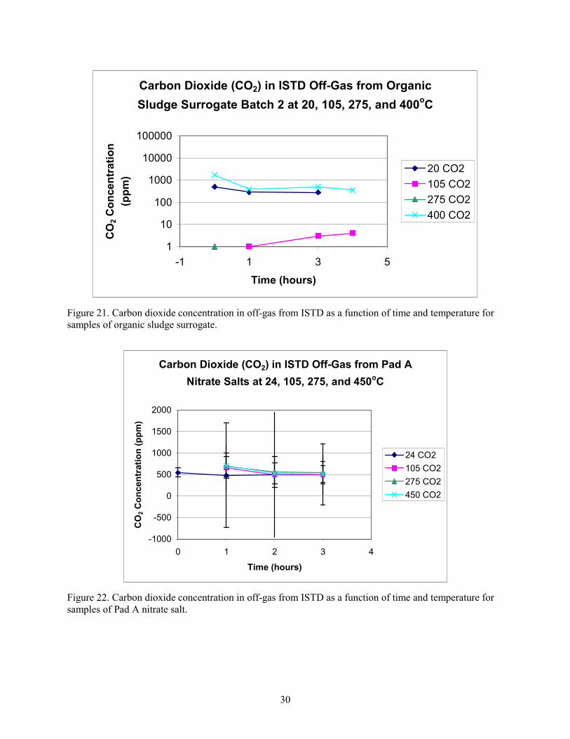
30
Carbon Dioxide (CO2) in ISTD Off-Gas from Organic
Sludge Surrogate Batch 2 at 20, 105, 275, and 400oC
1
10
100
1000
10000
100000
-1 1 3 5
Time (hours)
CO
2 C
on
cen
trati
on
(pp
m)
20 CO2
105 CO2
275 CO2
400 CO2
Figure 21. Carbon dioxide concentration in off-gas from ISTD as a function of time and temperature for
samples of organic sludge surrogate.
Carbon Dioxide (CO2) in ISTD Off-Gas from Pad A
Nitrate Salts at 24, 105, 275, and 450oC
-1000
-500
0
500
1000
1500
2000
0 1 2 3 4
Time (hours)
CO
2 C
on
cen
trati
on
(p
pm
)
24 CO2
105 CO2
275 CO2
450 CO2
Figure 22. Carbon dioxide concentration in off-gas from ISTD as a function of time and temperature for
samples of Pad A nitrate salt.
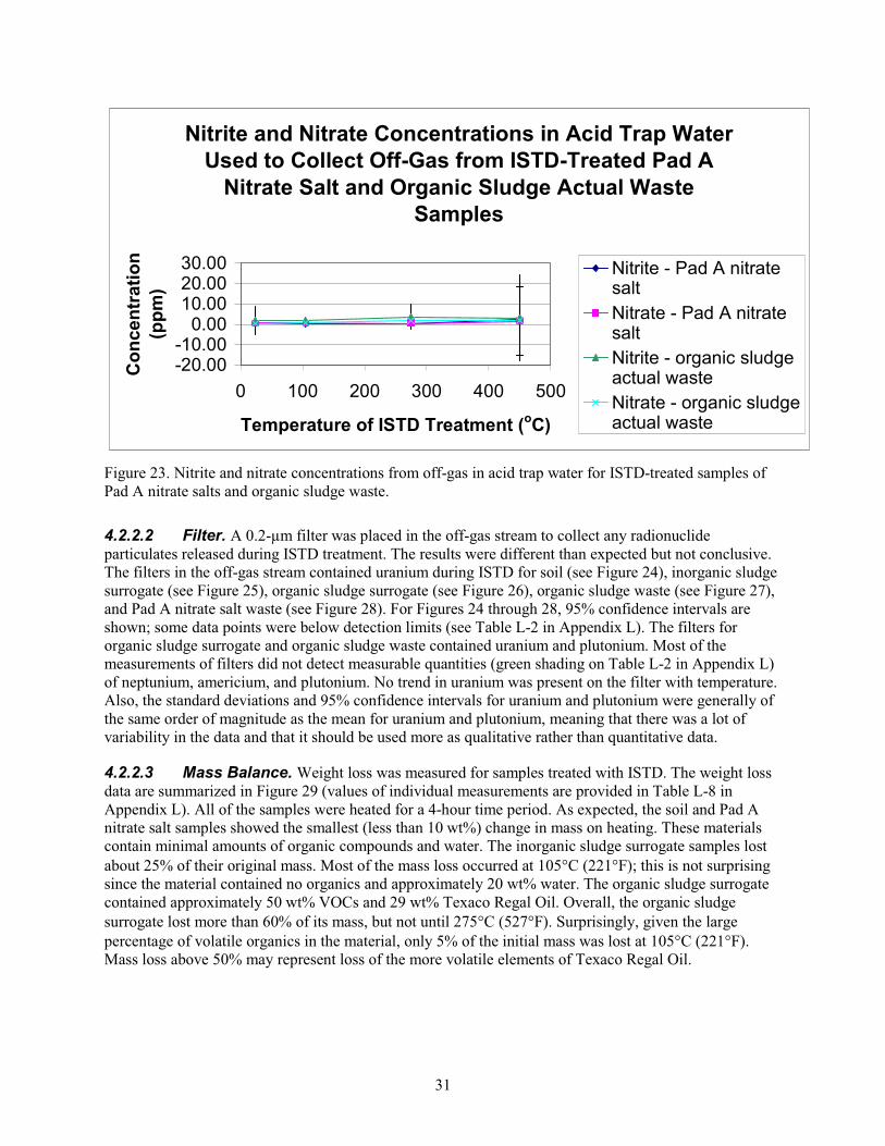
31
Nitrite and Nitrate Concentrations in Acid Trap Water
Used to Collect Off-Gas from ISTD-Treated Pad A
Nitrate Salt and Organic Sludge Actual Waste
Samples
-20.00-10.00
0.0010.0020.0030.00
0 100 200 300 400 500
Temperature of ISTD Treatment (oC)
Co
nc
en
tra
tio
n
(pp
m)
Nitrite - Pad A nitratesalt
Nitrate - Pad A nitratesalt
Nitrite - organic sludgeactual waste
Nitrate - organic sludgeactual waste
Figure 23. Nitrite and nitrate concentrations from off-gas in acid trap water for ISTD-treated samples of
Pad A nitrate salts and organic sludge waste.
4.2.2.2 Filter. A 0.2-μm filter was placed in the off-gas stream to collect any radionuclide
particulates released during ISTD treatment. The results were different than expected but not conclusive.
The filters in the off-gas stream contained uranium during ISTD for soil (see Figure 24), inorganic sludge
surrogate (see Figure 25), organic sludge surrogate (see Figure 26), organic sludge waste (see Figure 27),
and Pad A nitrate salt waste (see Figure 28). For Figures 24 through 28, 95% confidence intervals are
shown; some data points were below detection limits (see Table L-2 in Appendix L). The filters for
organic sludge surrogate and organic sludge waste contained uranium and plutonium. Most of the
measurements of filters did not detect measurable quantities (green shading on Table L-2 in Appendix L)
of neptunium, americium, and plutonium. No trend in uranium was present on the filter with temperature.
Also, the standard deviations and 95% confidence intervals for uranium and plutonium were generally of
the same order of magnitude as the mean for uranium and plutonium, meaning that there was a lot of
variability in the data and that it should be used more as qualitative rather than quantitative data.
4.2.2.3 Mass Balance. Weight loss was measured for samples treated with ISTD. The weight loss
data are summarized in Figure 29 (values of individual measurements are provided in Table L-8 in
Appendix L). All of the samples were heated for a 4-hour time period. As expected, the soil and Pad A
nitrate salt samples showed the smallest (less than 10 wt%) change in mass on heating. These materials
contain minimal amounts of organic compounds and water. The inorganic sludge surrogate samples lost
about 25% of their original mass. Most of the mass loss occurred at 105 C (221 F); this is not surprising
since the material contained no organics and approximately 20 wt% water. The organic sludge surrogate
contained approximately 50 wt% VOCs and 29 wt% Texaco Regal Oil. Overall, the organic sludge
surrogate lost more than 60% of its mass, but not until 275 C (527 F). Surprisingly, given the large
percentage of volatile organics in the material, only 5% of the initial mass was lost at 105 C (221 F).
Mass loss above 50% may represent loss of the more volatile elements of Texaco Regal Oil.
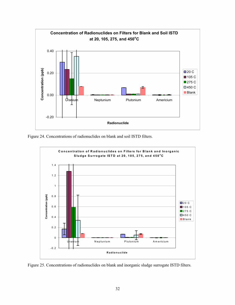
32
Concentration of Radionuclides on Filters for Blank and Soil ISTD
at 20, 105, 275, and 450oC
-0.20
0.00
0.20
0.40
Uranium Neptunium Plutonium Americium
Radionuclide
Co
nc
en
tra
tio
n (
pp
b)
20 C
105 C
275 C
450 C
Blank
Figure 24. Concentrations of radionuclides on blank and soil ISTD filters.
C o n c e n tra t io n o f R a d io n u c lid e s o n F ilte rs fo r B la n k a n d In o rg a n ic
S lu d g e S u rro g a te IS T D a t 2 0 , 1 0 5 , 2 7 5 , a n d 4 5 0oC
-0 .2
0
0 .2
0 .4
0 .6
0 .8
1
1 .2
1 .4
U ra n iu m N e p tu n iu m P lu to n iu m A m e ric iu m
R a d io n u c lid e
Co
ncen
trati
on
(p
pb
)
2 0 C
1 0 5 C
2 7 5 C
4 5 0 C
B la n k
Figure 25. Concentrations of radionuclides on blank and inorganic sludge surrogate ISTD filters.
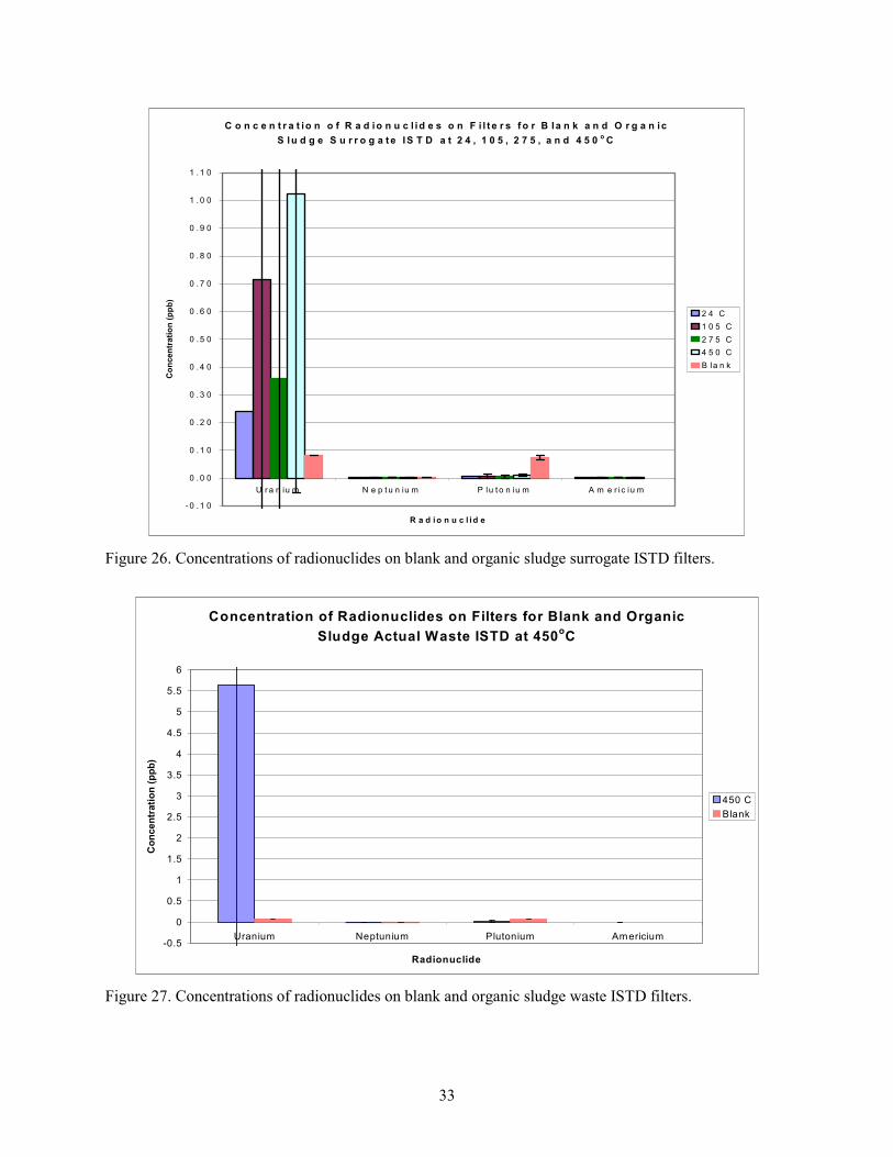
33
C o n c e n t r a t io n o f R a d io n u c l id e s o n F i l t e r s f o r B la n k a n d O r g a n ic
S lu d g e S u r r o g a t e IS T D a t 2 4 , 1 0 5 , 2 7 5 , a n d 4 5 0o
C
- 0 . 1 0
0 . 0 0
0 . 1 0
0 . 2 0
0 . 3 0
0 . 4 0
0 . 5 0
0 . 6 0
0 . 7 0
0 . 8 0
0 . 9 0
1 . 0 0
1 . 1 0
U r a n iu m N e p t u n iu m P lu t o n iu m A m e r ic iu m
R a d i o n u c l i d e
Co
ncen
trati
on
(p
pb
)
2 4 C
1 0 5 C
2 7 5 C
4 5 0 C
B la n k
Figure 26. Concentrations of radionuclides on blank and organic sludge surrogate ISTD filters.
Concentration of Radionuclides on Filters for Blank and Organic
Sludge Actual Waste ISTD at 450oC
-0.5
0
0.5
1
1.5
2
2.5
3
3.5
4
4.5
5
5.5
6
Uranium Neptunium Plutonium Americium
Radionuclide
Co
ncen
trati
on
(p
pb
)
450 C
Blank
Figure 27. Concentrations of radionuclides on blank and organic sludge waste ISTD filters.
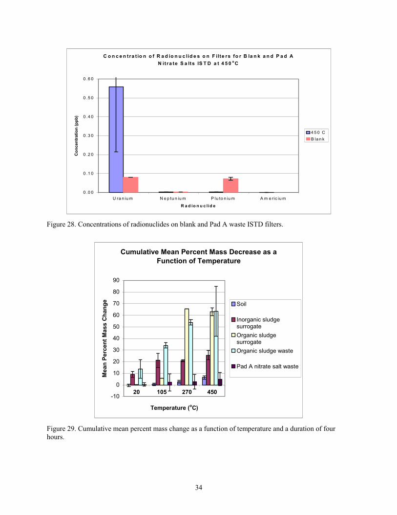
34
C o n c e n tra t io n o f R a d io n u c lid e s o n F ilte rs fo r B la n k a n d P a d A
N it ra te S a lts IS T D a t 4 5 0oC
0 .0 0
0 .1 0
0 .2 0
0 .3 0
0 .4 0
0 .5 0
0 .6 0
U ra n iu m N e p tu n iu m P lu to n iu m A m e ric iu m
R a d io n u c lid e
Co
ncen
trati
on
(p
pb
)
4 5 0 C
B la n k
Figure 28. Concentrations of radionuclides on blank and Pad A waste ISTD filters.
Cumulative Mean Percent Mass Decrease as a
Function of Temperature
-10
0
10
20
30
40
50
60
70
80
90
20 105 270 450
Temperature (oC)
Me
an
Pe
rce
nt
Ma
ss
Ch
an
ge
Soil
Inorganic sludgesurrogate
Organic sludgesurrogate
Organic sludge waste
Pad A nitrate salt waste
Figure 29. Cumulative mean percent mass change as a function of temperature and a duration of four
hours.

35
Compositional analyses (radionuclide and organic compounds) for two separately prepared batches
of organic sludge waste composite are shown in Table L-3 in Appendix L.
The concentration of radionuclides in each sample was measured before and after ISTD treatment.
The expected concentrations of radionuclides in samples after heating were calculated based on the mean
measured mass losses of samples of the material and the assumption that no radionuclides were released
from the sample during heating. The results are presented in Table L-4 in Appendix L. No data were
available on inorganic sludge surrogate. The data for organic sludge waste and one of the organic sludge
surrogate batches suggest that americium was lost during heating, but not uranium. The data for the Pad A
waste suggest that uranium and plutonium were lost during heating. Overall, the data showed
considerable variation. In several cases, the measured concentration of radionuclides was greater than the
expected concentration. This difference could be caused by the difference between the actual mass loss in
the measured sample and the average mass loss used to calculate the expected concentration or errors in
the measured concentration of radionuclides.
Table L-4 in Appendix L shows that the mean actinide concentrations increased by a factor of
1.5 to 2.5 in the posttreatment organic sludge waste composite, caused by the 50 to 60% mass loss
characteristic of treated organic sludge. The possible exception was americium, which apparently
decreased in concentration following heat treatment in the second trial; however, americium was not
detectable on gas stream filters (see Figures 26 and 27) or in the bubbler solution. The mean concentration
of uranium decreased substantially in posttreatment Pad A salt. This uranium also did not appear on the
filter downstream of the heated sample or in the bubbler solution, and thus, it must be hypothesized that
the uranium, americium, or both plated out on the quartz tubing immediately outside the furnace before
reaching the filter. Although it was heat taped, visual amounts of organic material also plated there.
In conclusion, the filter and composition data are not consistent with respect to release of
radionuclides during ISTD. Uranium and plutonium are seen on the filters for several waste materials,
while americium apparently decreased in organic sludge surrogate and waste samples during heating. In
all cases, the 95% confidence intervals are the same order of magnitude or larger than the mean values.
Given the inconsistent picture presented by the data, conclusions about the fate of radionuclides during
ISTD treatment cannot be made. Additional testing and controls (including a detailed full mass balance)
would be necessary to confirm the extent of potential radionuclide release during ISTD.
4.3 Determine the Degree of Hazardous Organic Contaminant and Nitrate Removal or Destruction from Soil and Waste
In situ thermal desorption can remove organic compounds from the waste. Lower temperatures
(100 to 200 C [212 to 392 F]) are appropriate for removing VOCs and water; this is the temperature
range of interest for the SDA. Higher treatment-zone temperatures (above 200 C [392 F]) are used for
removing and destroying semivolatile compounds. Treatment-zone temperatures of 400 to 500 C
(752 to 932 F) have been used to remove and destroy polychlorinated biphenyls at some field sites
(TerraTherm 2005b; TerraTherm 2005c; U.S. Navy 1997). The removal will be a combination of
vaporization and thermal destruction, depending on the temperature, materials, and oxygen present.
Section 4.3.1 covers work completed by MSE on nonradioactive surrogates. The MSE tests were larger
drum-scale tests. Section 4.3.2 covers ISTD of radioactive surrogate and waste completed at the INL Site,
and was performed on a smaller scale using surrogate and waste that was ISTD treated. The second set of
tests was used to confirm that the MSE drum-scale tests matched what would occur using the radioactive
waste and surrogate.