Embed Size (px)
Citation preview
pre
ssure
regula
tors
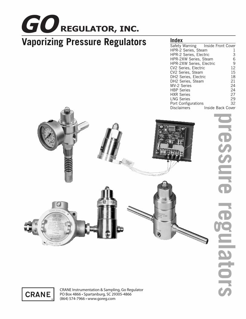
Vaporizing Pressure Regulators IndexSafety Warning Inside Front CoverHPR-2 Series, Steam 1HPR-2 Series, Electric 3HPR-2XW Series, Steam 6HPR-2XW Series, Electric 9CV2 Series, Electric 12CV2 Series, Steam 15DH2 Series, Electric 18DH2 Series, Steam 21MV-2 Series 24HBP Series 24HXR Series 27LNG Series 29Port Confi gurations 32Disclaimers Inside Back Cover
CRANE Instrumentation & Sampling, Go RegulatorPO Box 4866 • Spartanburg, SC 29305-4866(864) 574-7966 • www.goreg.com

SAFETY WARNING:GO Regulator products are designed for installation only by professional suitably qualifi ed licensed system installers
experienced in the applications and environments for which the products are intended. These products are intended for
integration into a system. Where these products are to be used with fl ammable or hazardous media, precautions must
be taken by the system designer and installer to ensure the safety of persons and property. Flammable or hazardous
media pose risks associated with fi re or explosion, as well as burning, poisoning or other injury or death to persons and/
or destruction of property. The system designer and installer must provide for the capture and control of such substances
from any vents in the product(s). The system installer must not permit any leakage or uncontrolled escape of hazardous
or fl ammable substances. The system operator must be trained to follow appropriate precautions and must inspect and
maintain the system and its components including the product(s) and at regular intervals in accordance with timescales
recommended by the supplier to prevent unacceptable wear or failure.
For Your SafetyIt is solely the responsibility of the system designer and user to select products suitable for their specifi c application
requirements and to ensure proper installation, operation, and maintenance of these products. When selecting products,
the total system design must be considered to ensure safe, trouble-free performance. Material compatibility, product
ratings and application details should be considered in the selection. Improper selection or use of products described
herein can cause personal injury or property damage.
Contact your authorized GO Regulator sales and service representative for information about additional sizes and special alloys.

pre
ssure
regula
tors
HPR-2 SeriesSteam Heated Regulators
The HPR-2 Series heated pressure
regulator is designed to supply heat to
samples entering instrumentation systems.
It can be used to preheat liquids, to
prevent condensation of gases or to
vaporize liquids prior to gas analysis.
The modular design of the HPR-2 consists
of heat exchanger and pressure control
sections. The pressure control section is
patterned after the time-proven design of
the PR-1 pressure reducing regulator and
provides the same excellent outlet pressure
stability. The heat exchanger section is
made up of a body and heat exchange
element. The heat exchange element uses
GO Regulator's unique spiral-wrapped
screen as the heat exchanger surface. This
screen has up to 100 square inches of heat
transfer area and precise design forces all
sample fl ow to pass through the element.
Typical ApplicationsAnalytical process sample conditioning systems:
• Petrochemical refi neries
• Chemical production facilities
• Pilot plants (chemical & petrochemical)
• LNG loading and off-loading points
• Natural gas pipeline sampling
Features & Benefi ts• Optional HASTELLOY® C and MONEL®
• Electropolished body with better than 25 Ra
fi nish in diaphragm cavity for an optimal sealing
surface
• Bubble-tight shutoff
• Modular pressure control and heat exchanger
assemblies allow for easy maintenance.
• Unique spiral-wrapped heat exchange element
provides up to 100 square inches of heat
transfer area.
• INCONEL® diaphragm standard.
CONSTRUCTION 316L stainless steel
OUTLET PRESSURES 0–10, 0–25, 0–50, 0–100, 0–250,
0-500, 0-750 and 0–1000 psig
INLET PRESSURE up to 6000 psig at 380° F (193° C)
OPERATING TEMPERATURE
up to 500° F (260° C)
CV COEFFICIENTS 0.06, 0.025, 0.2
INLET CONNECTIONS 1⁄8 ̋FNPT
OUTLET CONNECTIONS ¼˝ FNPT
Technical Data
1
Introduction

2
HPR-2 SeriesHow to Order
H2 – 1 Z 5 5 Q 3 C 1 1 1 4BODY MATERIAL
1 316L stainless steel,
stainless steel diaphragm
C 316L stainless steel, INCONEL® diaphragm
4 MONEL®, INCONEL® diaphragm
6 HASTELLOY® C, INCONEL® diaphragm
PORT CONFIGURATION
Z One inlet port, one outlet port
For more confi gurations, see pages 38-45
TEMPERATURE RANGE / HEATING TYPE
5 Steam
HEATER WATTAGE
5 Steam
SEAT MATERIAL
A Tefzel®
B Ceramic Filled PTFE
H PCTFE
Q PEEK™
FLOW COEFFICIENT (Cv)
3 0.06
5 0.2
C 0.025
OPTIONS (NOT REQUIRED)
B EB5 cleaningD Helium leak testE Pressure test certifi cateF Certifi cate of ConformityG CMTR
OPTIONS4 6000 psig inlet steam
heated (1-pc assembly)0 Other options
CAP ASSEMBLY1 Tamper-proof, standard,
stainless steel4 Tamper-proof, panel,
mount, stainless steel7 Tamper-proof, captured
vent, stainless steelJ Tamper-proof, capture
vent, panel mount, stainless steel
L BP-6 topworks
HEATER BLOCK PORTING1 Standard block2 Extra outlet blockFor more blocks, see pages 36-37
HEATER BLOCK TYPE1 Steam
OUTLET RANGEC 0–10 psigD 0–25 psigE 0–50 psigG 0–100 psigI 0–250 psigJ 0–500 psigW 0–750 psigK 0–1000 psig (BP-6 topworks)Maximum Temperature & Operating Inlet Pressures
HPR-2 Steam 2-piece Assembly
(Heater block and regulator body separate)
SEAT MATERIAL MAXIMUM TEMPERATURE @MAXIMUM OPERATING INLET
PRESSURE
Up to 380° F (193° C) @ 400 psig (2.76 MPa)
PEEK™ Up to 500° F (260° C) @ 3600 psig (24.82 MPa)
Outline & Mounting Dimensions
Standard items in bold
To Order, contact your local Distributor Link below:
www.goreg.com/distributor/index.htmVerify that your chosen part number is valid using the GO Wizards at
www.goreg.com/products/matrix/index.htm
Steam Tube 1/2" O.D. X 0.049 Wall
Panel Mount Option requiresØ 1.390" (35.3mm) minimum
diameter panel cut-out
Weight: 4.0 lbs (1.81 kg)
3.50 [89mm]
9.00 [229mm]
0.75 [19mm] TYP.10-32 UNF X 0.25 Min. Full Thds (2X)
1.00 [25mm]
StandardVent to
Atmosphere
5.67 [144mm]
1/8" FNPT Inlet
1/4" FNPT Outlet
0.50 [13mm]
Ø 2.0 [51mm]
Ø 2.25 [57mm]
Ceramic Filled PTFE,Tefzel®, & PCTFE
HPR-2 Steam 1-piece Assembly
(Integral heater block and regulator)
SEAT MATERIAL MAXIMUM TEMPERATURE @MAXIMUM OPERATING INLET
PRESSURE
Up to 380° F (193° C) @ 400 psig (2.76 MPa)
PEEK™ Up to 380° F (193° C) @ 6000 psig (41.37 MPa)
Ceramic Filled PTFE,Tefzel®, & PCTFE
NOTE: Contact the factory for any additional requirements.
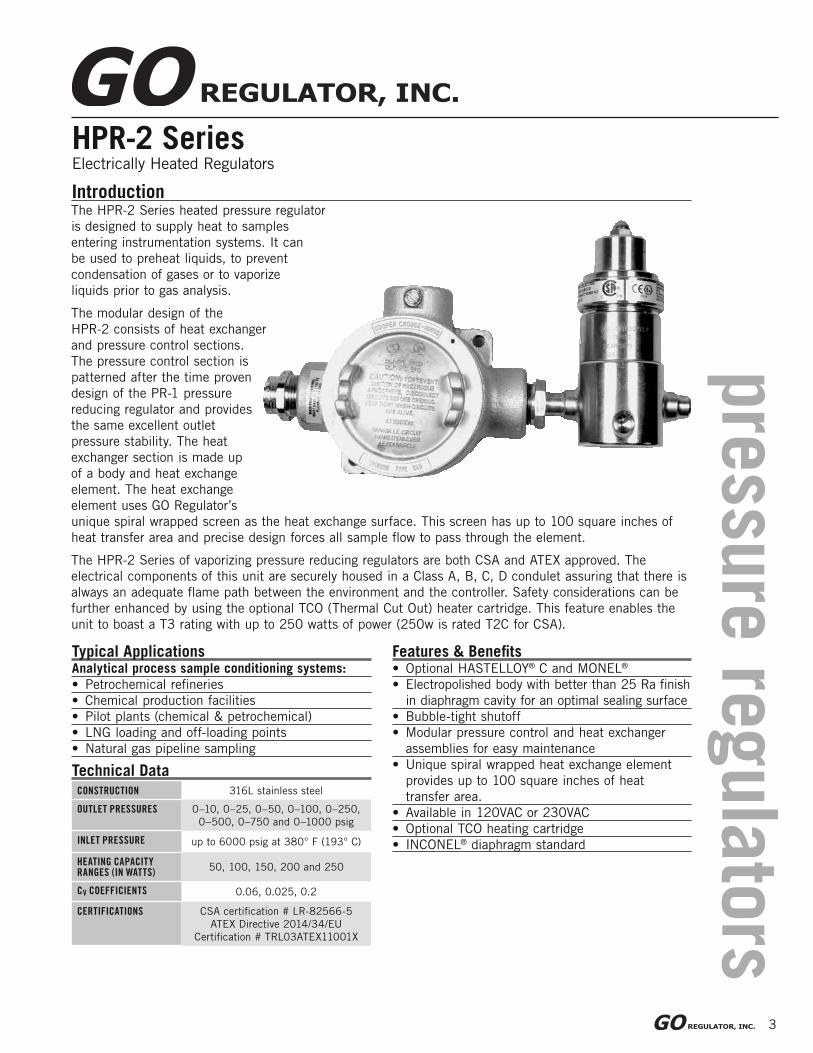
HPR-2 SeriesElectrically Heated Regulators
Features & Benefi ts• Optional HASTELLOY® C and MONEL®
• Electropolished body with better than 25 Ra fi nish
in diaphragm cavity for an optimal sealing surface
• Bubble-tight shutoff
• Modular pressure control and heat exchanger
assemblies for easy maintenance
• Unique spiral wrapped heat exchange element
provides up to 100 square inches of heat
transfer area.
• Available in 120VAC or 230VAC
• Optional TCO heating cartridge
• INCONEL® diaphragm standard
Introduction
Typical ApplicationsAnalytical process sample conditioning systems:
• Petrochemical refi neries
• Chemical production facilities
• Pilot plants (chemical & petrochemical)
• LNG loading and off-loading points
• Natural gas pipeline sampling
CONSTRUCTION 316L stainless steel
OUTLET PRESSURES 0–10, 0–25, 0–50, 0–100, 0–250,
0–500, 0–750 and 0–1000 psig
INLET PRESSURE up to 6000 psig at 380° F (193° C)
HEATING CAPACITY RANGES (IN WATTS)
50, 100, 150, 200 and 250
CV COEFFICIENTS 0.06, 0.025, 0.2
CERTIFICATIONS CSA certifi cation # LR-82566-5
ATEX Directive 2014/34/EU
Certifi cation # TRL03ATEX11001X
Technical Data
The HPR-2 Series heated pressure regulator
is designed to supply heat to samples
entering instrumentation systems. It can
be used to preheat liquids, to prevent
condensation of gases or to vaporize
liquids prior to gas analysis.
The modular design of the
HPR-2 consists of heat exchanger
and pressure control sections.
The pressure control section is
patterned after the time proven
design of the PR-1 pressure
reducing regulator and provides
the same excellent outlet
pressure stability. The heat
exchanger section is made up
of a body and heat exchange
element. The heat exchange
element uses GO Regulator’s
unique spiral wrapped screen as the heat exchange surface. This screen has up to 100 square inches of
heat transfer area and precise design forces all sample fl ow to pass through the element.
The HPR-2 Series of vaporizing pressure reducing regulators are both CSA and ATEX approved. The
electrical components of this unit are securely housed in a Class A, B, C, D condulet assuring that there is
always an adequate fl ame path between the environment and the controller. Safety considerations can be
further enhanced by using the optional TCO (Thermal Cut Out) heater cartridge. This feature enables the
unit to boast a T3 rating with up to 250 watts of power (250w is rated T2C for CSA).
3
pre
ssure
regula
tors

4
HPR-2 Series
How to Order
Maximum Temperature & Operating Inlet Pressures
HPR-2 Electric 2-piece Assembly
(Heater block and regulator body separate)
SEAT MATERIALMAXIMUM
TEMPERATURE @MAXIMUM OPERATING
INLET PRESSURE
Tefzel®
Ceramic Filled PTFE
& PCTFE
Up to 175° F (80° C) @ 3600 psig (24.82 MPa)
176° F to 300° F
(80° C to 148° C)@ 1000 psig (6.90 MPa)
301° F to 380° F
(148° C to 193° C)@ 400 psig (2.76 MPa)
PEEK™ Up to 380° F (193° C) @ 3600 psig (24.82 MPa)
HPR-2 Electric 1-piece Assembly
(Integral heater block and regulator)
SEAT MATERIALMAXIMUM
TEMPERATURE @MAXIMUM OPERATING INLET
PRESSURE
Tefzel®
& Ceramic Filled PTFE
Up to 175° F (80° C) @ 3600 psig (24.82 MPa)
176° F to 300° F
(80° C to 148° C)@ 1000 psig (6.90 MPa)
301° F to 380° F
(148° C to 193° C)@ 400 psig (2.76 MPa)
PCTFE
Up to 175° F (80° C) @ 6000 psig (41.37 MPa)
176° F to 300° F
(80° C to 148° C)@ 1000 psig (6.90 MPa)
301° F to 380° F
(148° C to 193° C)@ 400 psig (2.76 MPa)
PEEK™ Up to 380° F (193° C) @ 6000 psig (41.37 MPa)
Standard items in bold
To Order, contact your local Distributor Link below:
www.goreg.com/distributor/index.htmVerify that your chosen part number is valid using the GO Wizards at
www.goreg.com/products/matrix/index.htm
H2 – 4 Z 3 3 H 3 G 4 1 4 7BODY MATERIAL
1 316L stainless steel,
stainless steel diaphragm
C 316L stainless steel, INCONEL® diaphragm
4 MONEL®, INCONEL® diaphragm
6 HASTELLOY® C, INCONEL® diaphragm
PORT CONFIGURATION
Z One inlet port, one outlet port
For more confi gurations, see pages 38-45
TEMPERATURE RANGE / HEATING TYPE
1 55°-85°F (13-29°C)
2 75°-175°F (24-80°C)
3 130°-300°F (54-149°C)
4 260°-380°F (126-194°C)
8 No electronics
HEATER WATTAGE
1 40W
2 50W
3 100W
4 150W
8 200W
9 250W (T2C/230°C for CSA)
6 No electronics
SEAT MATERIAL
A Tefzel®
B Ceramic Filled PTFE
H PCTFE
Q PEEK™
FLOW COEFFICIENT (Cv)
3 0.06
5 0.2
C 0.025
OPTIONS (NOT REQUIRED)
B EB5 cleaningD Helium leak testE Pressure test certifi cateF Certifi cate of ConformityG CMTR
OPTIONS1 TCO thermistor5 6000 psig inlet w/TCO
thermistor (1-pc assy.)7 6000 psig inlet w/standard
thermistor (1-pc assy.)0 Other options
CAP ASSEMBLY1 Tamper-proof, standard,
stainless steel4 Tamper-proof, panel,
mount, stainless steel7 Tamper-proof, captured
vent, stainless steelJ Tamper-proof, captured
vent, panel mount, stainless steel
L BP-6 topworks
HEATER BLOCK PORTING1 Standard block2 Extra outlet blockFor more blocks, see pages 36-37
HEATER BLOCK TYPE3 120 VAC4 230 VAC5 No electronics
OUTLET RANGEC 0–10 psigD 0–25 psigE 0–50 psigG 0–100 psigI 0–250 psigJ 0–500 psigW 0–750 psigK 0–1000 psig (BP-6 topworks)
NOTE: 1. Contact the factory for any additional requirements.
2. Units that will be used for fl ammable liquid or gas with fi re point at 200°C or below
require the TCO Thermistor. It is also recommended to use the 1-PC body option. In
addition, Tefzel and PCTFE seats in these units are recommended to use the
captured vent cap option which provides for venting to a safe location.
5
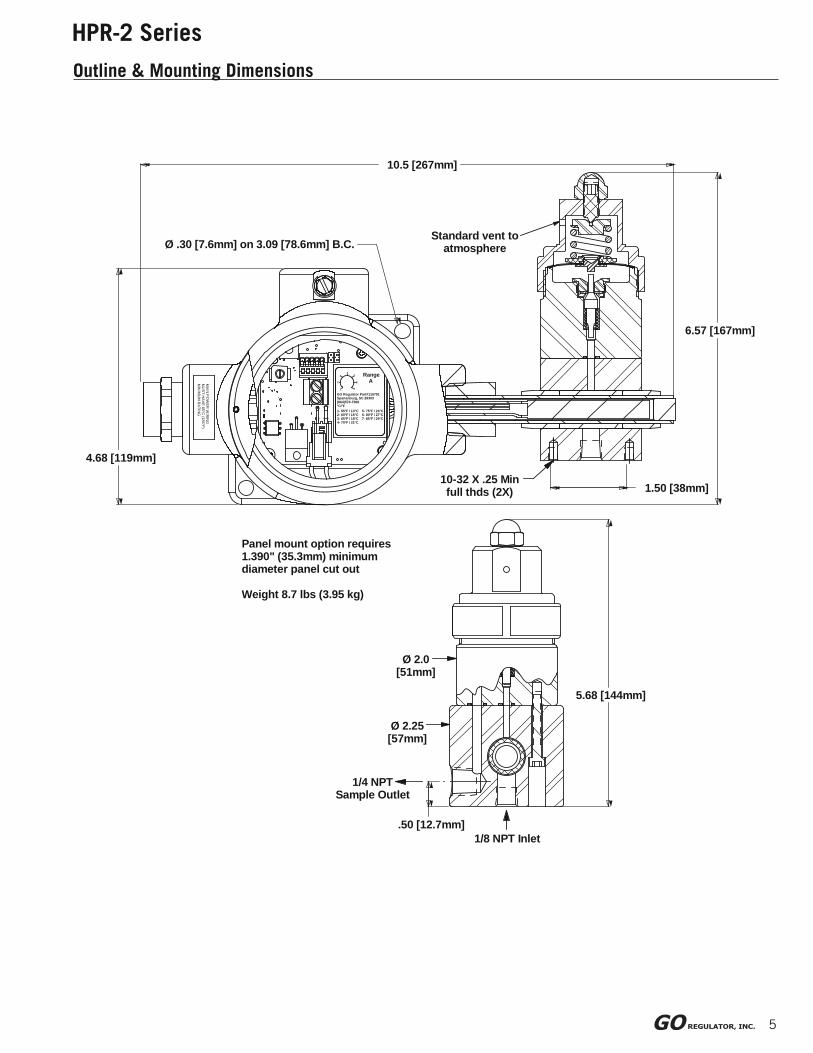
HPR-2 Series
Outline & Mounting Dimensions
MA
IN P
OW
ER
WIR
ING
MU
ST HA
VE 85°C
(185°F)M
INIM
UM
RA
TING
Ø 2.0 [51mm]
Ø 2.25 [57mm]
.50 [12.7mm]
1/4 NPT Sample Outlet
Panel mount option requires 1.390" (35.3mm) minimum diameter panel cut out
Weight 8.7 lbs (3.95 kg)
5.68 [144mm]
1/8 NPT Inlet
6.57 [167mm]
10.5 [267mm]
4.68 [119mm]
1- 55°F / 13°C 5- 75°F / 24°C2- 60°F / 16°C 6- 80°F / 27°C3- 65°F / 18°C 7- 85°F / 29°C4- 70°F / 21°C
RangeA2
1
4
6
7
53
GO Regulator Part#115791Spartanburg, SC 29303(864)574-7966°C/°F
Ø .30 [7.6mm] on 3.09 [78.6mm] B.C.
1.50 [38mm]10-32 X .25 Min full thds (2X)
Standard vent to atmosphere

Product HeaderProduct Subhead
pre
ssure
regula
tors
6
HPR-2XW SeriesSteam Heated Pressure Regulator
Features & Benefi ts• Optional HASTELLOY® C and MONEL®
• Electropolished body with better than 25 Ra
fi nish in diaphragm cavity for an optimal sealing
surface
• Bubble-tight shutoff
• Modular pressure control and heat exchanger
assemblies for easy maintenance
• Unique spiral wrapped heat exchange element
provides up to 100 square inches of heat
transfer area.
• INCONEL® diaphragm standard.
Typical ApplicationsAnalytical process sample conditioning systems:
• Petrochemical refi neries
• Chemical production facilities
• Pilot plants (chemical & petrochemical)
• LNG loading and off-loading points
• Natural gas pipeline sampling
CONSTRUCTION 316L stainless steel
OUTLET PRESSURES 0–10, 0–25, 0–50, 0–100, 0–250,
0–500, 0–750 and 0–1000 psig
INLET PRESSURE up to 6000 psig at 380° F (193° C)
OPERATING TEMPERATURE
up to 500° F (260° C)
CV COEFFICIENTS 0.06, 0.025, 0.2
INLET CONNECTIONS 1⁄8˝ FNPT
OUTLET CONNECTIONS ¼˝ FNPT
Technical Data
The HPR-2XW Series heated pressure
regulator is designed to supply heat
to samples entering instrumentation
systems. It can be used to preheat
liquids, to prevent condensation of
gases or to vaporize liquids prior to gas
analysis.
The modular design of the HPR-2XW
consists of heat exchanger and pressure
control sections. The pressure control
section is patterned after the time
proven design of the PR-1 pressure
reducing regulator and provides the
same excellent outlet pressure stability.
The heat exchanger section is made up
of a body and heat exchange element.
The heat exchange element uses GO
Regulator’s unique spiral wrapped screen
as the heat exchange surface. This screen has up to 100 square inches of heat transfer area and precise
design forces all sample fl ow to pass through the element.
Completing this modular design is the incorporation of a removable heat exchange unit. This allows the
user to remove and clean or replace the exchanger. This is especially useful when heating dirty liquids or
liquids that polymerize and clog the heat exchange screen.
Introduction
7
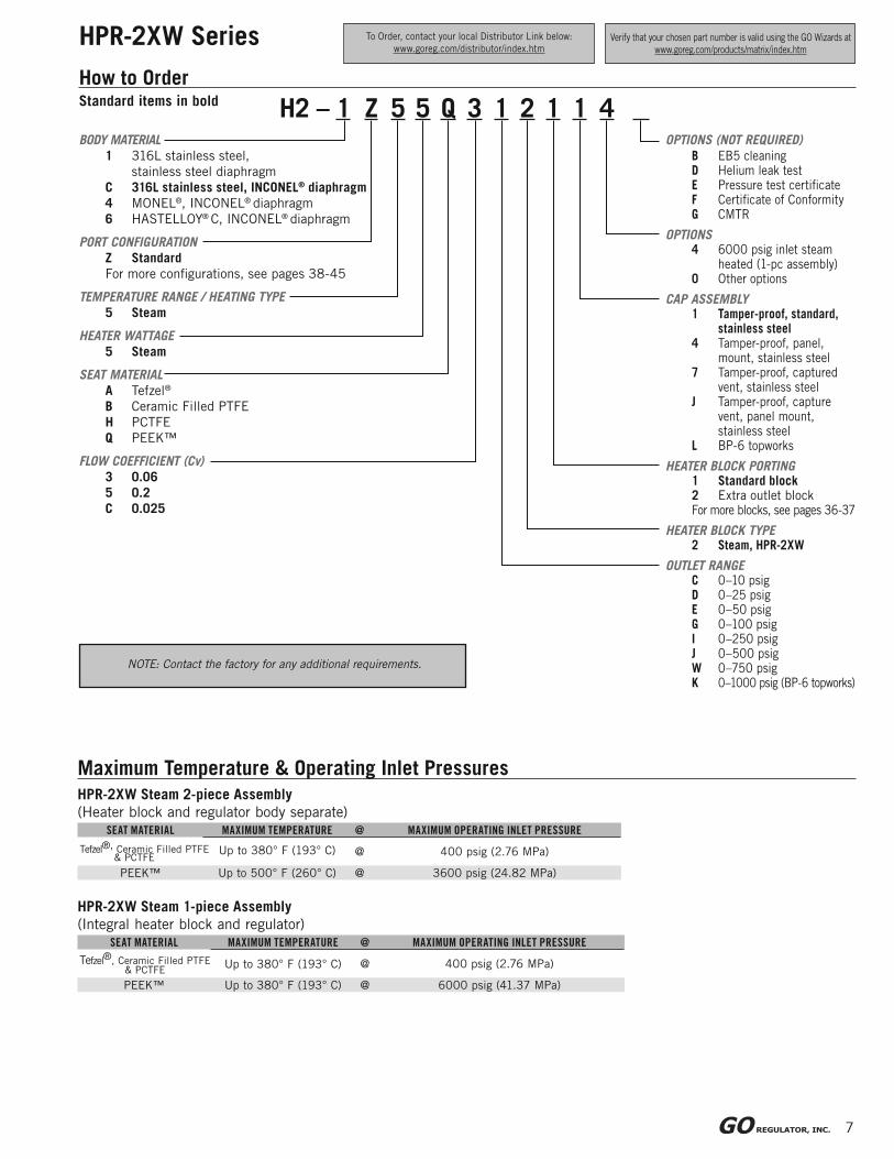
HPR-2XW Series
How to Order
Maximum Temperature & Operating Inlet PressuresHPR-2XW Steam 2-piece Assembly
(Heater block and regulator body separate)SEAT MATERIAL MAXIMUM TEMPERATURE @ MAXIMUM OPERATING INLET PRESSURE
Up to 380° F (193° C) @ 400 psig (2.76 MPa)
PEEK™ Up to 500° F (260° C) @ 3600 psig (24.82 MPa)
HPR-2XW Steam 1-piece Assembly
(Integral heater block and regulator)SEAT MATERIAL MAXIMUM TEMPERATURE @ MAXIMUM OPERATING INLET PRESSURE
Up to 380° F (193° C) @ 400 psig (2.76 MPa)
PEEK™ Up to 380° F (193° C) @ 6000 psig (41.37 MPa)
Tefzel®, Ceramic Filled PTFE& PCTFE
NOTE: Contact the factory for any additional requirements.
H2 – 1 Z 5 5 Q 3 1 2 1 1 4BODY MATERIAL
1 316L stainless steel,
stainless steel diaphragm
C 316L stainless steel, INCONEL® diaphragm
4 MONEL®, INCONEL® diaphragm
6 HASTELLOY® C, INCONEL® diaphragm
PORT CONFIGURATION
Z Standard
For more confi gurations, see pages 38-45
TEMPERATURE RANGE / HEATING TYPE
5 Steam
HEATER WATTAGE
5 Steam
SEAT MATERIAL
A Tefzel®
B Ceramic Filled PTFE
H PCTFE
Q PEEK™
FLOW COEFFICIENT (Cv)
3 0.06
5 0.2
C 0.025
OPTIONS (NOT REQUIRED)
B EB5 cleaningD Helium leak testE Pressure test certifi cateF Certifi cate of ConformityG CMTR
OPTIONS4 6000 psig inlet steam
heated (1-pc assembly)0 Other options
CAP ASSEMBLY1 Tamper-proof, standard,
stainless steel4 Tamper-proof, panel,
mount, stainless steel7 Tamper-proof, captured
vent, stainless steelJ Tamper-proof, capture
vent, panel mount, stainless steel
L BP-6 topworks
HEATER BLOCK PORTING1 Standard block2 Extra outlet blockFor more blocks, see pages 36-37
HEATER BLOCK TYPE2 Steam, HPR-2XW
OUTLET RANGEC 0–10 psigD 0–25 psigE 0–50 psigG 0–100 psigI 0–250 psigJ 0–500 psigW 0–750 psigK 0–1000 psig (BP-6 topworks)
Standard items in bold
To Order, contact your local Distributor Link below:
www.goreg.com/distributor/index.htmVerify that your chosen part number is valid using the GO Wizards at
www.goreg.com/products/matrix/index.htm
Tefzel®, Ceramic Filled PTFE
& PCTFE
8
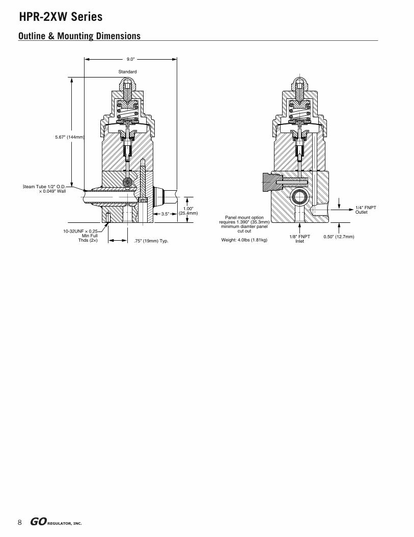
HPR-2XW Series
Outline & Mounting Dimensions
5.67" (144mm)
Standard
1.00"(25.4mm)3.5"
9.0"
.75" (19mm) Typ.
1/4" FNPTOutlet
1/8" FNPTInlet
0.50" (12.7mm)
Panel mount optionrequires 1.390" (35.3mm)minimum diamter panel
cut out
Weight: 4.0lbs (1.81kg)
10-32UNF × 0.25Min Full
Thds (2×)
Steam Tube 1/2" O.D.× 0.049" Wall

9
HPR-2XW SeriesElectrically Heated Pressure Regulator
Features & Benefi ts• Optional HASTELLOY® C-276 & MONEL®
• Electropolished body with better than 25 Ra
fi nish in diaphragm cavity for an optimal sealing
surface
• Bubble-tight shutoff
• Modular pressure control and heat exchanger
assemblies for easy maintenance
• Unique spiral wrapped heat exchange element
provides up to 100 square inches of heat
transfer area.
• Available in 120VAC or 230VAC
• Optional TCO for T3 operation
• INCONEL® diaphragm standard
Introduction
Typical ApplicationsAnalytical process sample conditioning systems:
• Petrochemical refi neries
• Chemical production facilities
• Pilot plants (chemical & petrochemical)
• LNG loading and off-loading points
• Natural gas pipeline sampling
CONSTRUCTION 316L stainless steel
OUTLET PRESSURES 0–10, 0–25, 0–50, 0–100, 0–250,
0–500, 0–750, and 0–1000 psig
OPERATING TEMPERATURE
up to 380° F (193° C)
HEATING CAPACITY RANGES (IN WATTS)
40, 50, 100, 150, 200, and 250
CV COEFFICIENTS 0.06, 0.025, 0.2
CERTIFICATIONS CSA certifi cation # LR-82566-5
ATEX Directive 2014/34/EU
Certifi cation # TRL03ATEX11001X
Technical Data
The HPR-2XW Series heated pressure regulator is designed to supply heat to samples entering instrumentation systems.
It can be used to preheat liquids, to prevent condensation of gases or to vaporize liquids prior to gas analysis.
The modular design of the HPR-2XW consists of heat exchanger and pressure control sections. The pressure control
section is patterned after the time-proven design of the PR-1 pressure reducing regulator and provides the same
excellent outlet pressure stability. The heat exchanger section is made up of a body and heat exchange element. The
heat exchange element uses GO Regulator’s unique spiral wrapped screen as the heat exchanger surface. This screen
has up to 100 square inches of heat transfer area and precise design forces all sample fl ow to pass through the element.
Completing this modular design is the incorporation of a removable heat exchanger unit. This allows the user to remove
and clean, or replace the exchanger. This is especially useful when heating dirty liquids or
liquids that polymerize and clog the heat exchange screen.
The HPR-2 Series of vaporizing pressure
reducing regulators are both CSA and ATEX
approved. The electrical components of
this unit are securely housed in a Class
A,B,C,D condulet assuring that there is
always an adequate fl ame path between
the environment and the controller. Safety
considerations can be further enhanced
by using the optional TCO (Thermal Cut
Out) heater cartridge. This feature enables
the unit to boast a T3 rating with up to
250 watts of power. (CSA T2D rating for
250W).
pre
ssure
regula
tors
10
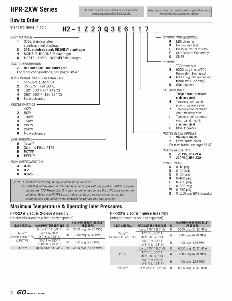
HPR-2XW Series
How to Order
Maximum Temperature & Operating Inlet PressuresHPR-2XW Electric 2-piece Assembly
(Heater block and regulator body separate)
SEAT MATERIAL MAXIMUM TEMPERATURE @MAXIMUM OPERATING INLET
PRESSURE
Tefzel®
Ceramic Filled PTFE
& PCTFE
Up to 175° F (80° C) @ 3600 psig (24.82 MPa)
176° F to 300° F
(80° C to 148° C)@ 1000 psig (6.90 MPa)
301° F to 380° F
(148° C to 193° C)@ 400 psig (2.76 MPa)
PEEK™ Up to 380° F (193° C) @ 3600 psig (24.82 MPa)
HPR-2XW Electric 1-piece Assembly
(Integral heater block and regulator)
SEAT MATERIAL MAXIMUM TEMPERATURE @MAXIMUM OPERATING INLET
PRESSURE
Tefzel®
Ceramic Filled PTFE
Up to 175° F (80° C) @ 3600 psig (24.82 MPa)
176° F to 300° F
(80° C to 148° C)@ 1000 psig (6.90 MPa)
301° F to 380° F
(148° C to 193° C)@ 400 psig (2.76 MPa)
PCTFE
Up to 175° F (80° C) @ 6000 psig (41.37 MPa)
176° F to 300° F
(80° C to 148° C)@ 1000 psig (6.90 MPa)
301° F to 380° F
(148° C to 193° C)@ 400 psig (2.76 MPa)
PEEK™ Up to 380° F (193° C) @ 6000 psig (41.37 MPa)
H2 – 1 Z 2 3 Q 3 E 6 1 1 7BODY MATERIAL
1 316L stainless steel,
stainless steel diaphragm
C 316L stainless steel, INCONEL® diaphragm
4 MONEL®, INCONEL® diaphragm
6 HASTELLOY® C, INCONEL® diaphragm
PORT CONFIGURATION
Z One inlet port, one outlet port
For more confi gurations, see pages 38-45
TEMPERATURE RANGE / HEATING TYPE
1 55°-85°F (13-29°C)
2 75°-175°F (24-80°C)
3 130°-300°F (54-149°C)
4 260°-380°F (126-194°C)
6 No electronics
HEATER WATTAGE
1 40W
2 50W
3 100W
4 150W
8 200W
9 250W
6 No electronics
SEAT MATERIAL
A Tefzel®
B Ceramic Filled PTFE
H PCTFE
Q PEEK™
FLOW COEFFICIENT (Cv)
3 0.06
5 0.2
C 0.025
OPTIONS (NOT REQUIRED)
B EB5 cleaningD Helium leak testE Pressure test certifi cateF Certifi cate of ConformityG CMTR
OPTIONS1 TCO thermistor5 6000 psig inlet w/TCO
thermistor (1-pc assy.)4 6000 psig inlet w/standard
thermistor (1-pc assy.)0 Other options
CAP ASSEMBLY1 Tamper-proof, standard,
stainless steel4 Tamper-proof, panel,
mount, stainless steel7 Tamper-proof, captured
vent, stainless steelJ Tamper-proof, captured
vent, panel mount, stainless steel
L BP-6 topworks
HEATER BLOCK PORTING1 Standard block2 Extra outlet blockFor more blocks, see pages 36-37
HEATER BLOCK TYPE6 120 VAC, HPR-2XW7 230 VAC, HPR-2XW
OUTLET RANGEC 0–10 psigD 0–25 psigE 0–50 psigG 0–100 psigI 0–250 psigJ 0–500 psigW 0–750 psigK 0–1000 psig (BP-6 topworks)
Standard items in bold
To Order, contact your local Distributor Link below:
www.goreg.com/distributor/index.htmVerify that your chosen part number is valid using the GO Wizards at
www.goreg.com/products/matrix/index.htm
NOTE: 1. Contact the factory for any additional requirements.
2. Units that will be used for fl ammable liquid or gas with fi re point at 200°C or below
require the TCO Thermistor. It is also recommended to use the 1-PC body option. In
addition, Tefzel and PCTFE seats in these units are recommended to use the
captured vent cap option which provides for venting to a safe location.

11
HPR-2XW Series
Maximum Temperature & Operating Inlet Pressures
MA
IN P
OW
ER
WIR
ING
MU
ST HA
VE 85°C
(185°F)M
INIM
UM
RA
TING
Ø 2.0 [51mm]
Ø 2.25 [57mm]
.50 [12.7mm]
1/4 NPT Sample Outlet
Panel mount option requires 1.390" (35.3mm) minimum diameter panel cut out
Weight 8.7 lbs (3.95 kg)
5.68 [144mm]
1/8 NPT Inlet
6.57 [167mm]
10.5 [267mm]
4.68 [119mm]
1- 55°F / 13°C 5- 75°F / 24°C2- 60°F / 16°C 6- 80°F / 27°C3- 65°F / 18°C 7- 85°F / 29°C4- 70°F / 21°C
RangeA2
1
4
6
7
53
GO Regulator Part#115791Spartanburg, SC 29303(864)574-7966°C/°F
Ø .30 [7.6mm) on 3.09 [78.6mm) B.C.
1.50 [38mm]10-32 X .25 Min full thds (2X)
Standard vent to atmosphere
pre
ssure
regula
tors
12
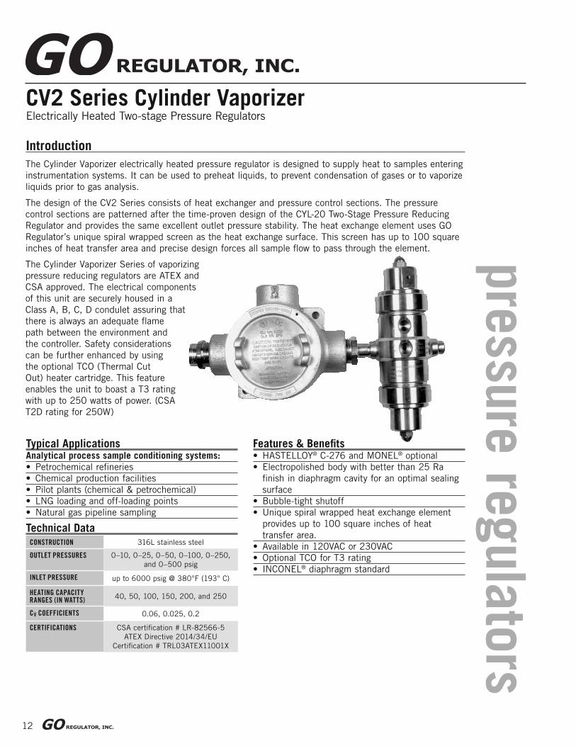
CV2 Series Cylinder VaporizerElectrically Heated Two-stage Pressure Regulators
Features & Benefi ts• HASTELLOY® C-276 and MONEL® optional
• Electropolished body with better than 25 Ra
fi nish in diaphragm cavity for an optimal sealing
surface
• Bubble-tight shutoff
• Unique spiral wrapped heat exchange element
provides up to 100 square inches of heat
transfer area.
• Available in 120VAC or 230VAC
• Optional TCO for T3 rating
• INCONEL® diaphragm standard
Introduction
Typical ApplicationsAnalytical process sample conditioning systems:
• Petrochemical refi neries
• Chemical production facilities
• Pilot plants (chemical & petrochemical)
• LNG loading and off-loading points
• Natural gas pipeline sampling
CONSTRUCTION 316L stainless steel
OUTLET PRESSURES 0–10, 0–25, 0–50, 0–100, 0–250,
and 0–500 psig
INLET PRESSURE up to 6000 psig @ 380°F (193° C)
HEATING CAPACITY RANGES (IN WATTS)
40, 50, 100, 150, 200, and 250
CV COEFFICIENTS 0.06, 0.025, 0.2
CERTIFICATIONS CSA certifi cation # LR-82566-5
ATEX Directive 2014/34/EU
Certifi cation # TRL03ATEX11001X
Technical Data
The Cylinder Vaporizer electrically heated pressure regulator is designed to supply heat to samples entering
instrumentation systems. It can be used to preheat liquids, to prevent condensation of gases or to vaporize
liquids prior to gas analysis.
The design of the CV2 Series consists of heat exchanger and pressure control sections. The pressure
control sections are patterned after the time-proven design of the CYL-20 Two-Stage Pressure Reducing
Regulator and provides the same excellent outlet pressure stability. The heat exchange element uses GO
Regulator’s unique spiral wrapped screen as the heat exchange surface. This screen has up to 100 square
inches of heat transfer area and precise design forces all sample fl ow to pass through the element.
The Cylinder Vaporizer Series of vaporizing
pressure reducing regulators are ATEX and
CSA approved. The electrical components
of this unit are securely housed in a
Class A, B, C, D condulet assuring that
there is always an adequate fl ame
path between the environment and
the controller. Safety considerations
can be further enhanced by using
the optional TCO (Thermal Cut
Out) heater cartridge. This feature
enables the unit to boast a T3 rating
with up to 250 watts of power. (CSA
T2D rating for 250W)
13
CV2 Series Cylinder Vaporizer
2nd Stage1st Stage
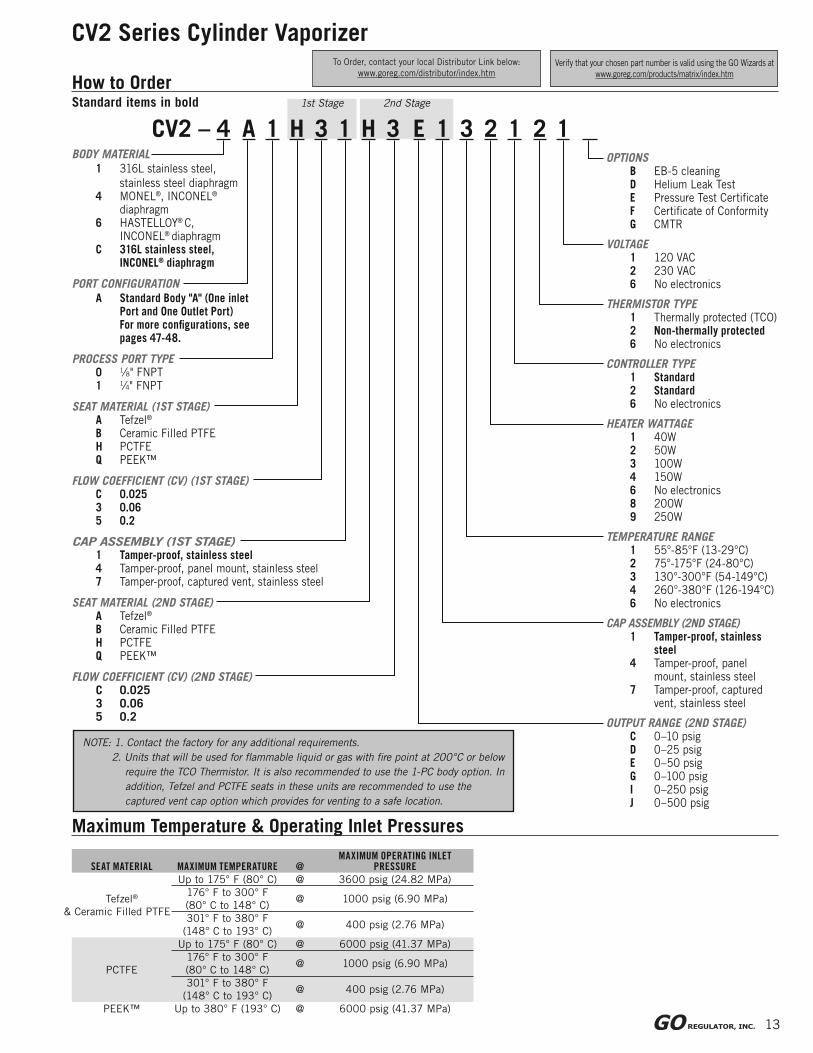
How to Order
CV2 – 4 A 1 H 3 1 H 3 E 1 3 2 1 2 1BODY MATERIAL
1 316L stainless steel,
stainless steel diaphragm4 MONEL®, INCONEL®
diaphragm6 HASTELLOY® C, INCONEL® diaphragmC 316L stainless steel, INCONEL® diaphragm
PORT CONFIGURATION
A Standard Body "A" (One inletPort and One Outlet Port)For more confi gurations, see
pages 47-48.
PROCESS PORT TYPE0 1⁄8" FNPT1 1⁄4" FNPT
SEAT MATERIAL (1ST STAGE)A Tefzel®
B Ceramic Filled PTFEH PCTFE Q PEEK™
FLOW COEFFICIENT (CV) (1ST STAGE)C 0.0253 0.065 0.2
CAP ASSEMBLY (1ST STAGE)1 Tamper-proof, stainless steel4 Tamper-proof, panel mount, stainless steel7 Tamper-proof, captured vent, stainless steel
SEAT MATERIAL (2ND STAGE)A Tefzel®
B Ceramic Filled PTFEH PCTFE Q PEEK™
FLOW COEFFICIENT (CV) (2ND STAGE)C 0.0253 0.065 0.2
OPTIONSB EB-5 cleaningD Helium Leak TestE Pressure Test Certifi cateF Certifi cate of ConformityG CMTR
VOLTAGE1 120 VAC2 230 VAC6 No electronics
THERMISTOR TYPE1 Thermally protected (TCO)2 Non-thermally protected6 No electronics
CONTROLLER TYPE1 Standard2 Standard6 No electronics
HEATER WATTAGE1 40W2 50W3 100W4 150W6 No electronics8 200W9 250W
TEMPERATURE RANGE1 55°-85°F (13-29°C)2 75°-175°F (24-80°C)3 130°-300°F (54-149°C)4 260°-380°F (126-194°C)6 No electronics
CAP ASSEMBLY (2ND STAGE)1 Tamper-proof, stainless
steel4 Tamper-proof, panel
mount, stainless steel7 Tamper-proof, captured
vent, stainless steel
OUTPUT RANGE (2ND STAGE)C 0–10 psigD 0–25 psigE 0–50 psigG 0–100 psigI 0–250 psigJ 0–500 psig
Maximum Temperature & Operating Inlet Pressures
SEAT MATERIAL MAXIMUM TEMPERATURE @MAXIMUM OPERATING INLET
PRESSURE
Tefzel®
& Ceramic Filled PTFE
Up to 175° F (80° C) @ 3600 psig (24.82 MPa)
176° F to 300° F
(80° C to 148° C)@ 1000 psig (6.90 MPa)
301° F to 380° F
(148° C to 193° C)@ 400 psig (2.76 MPa)
PCTFE
Up to 175° F (80° C) @ 6000 psig (41.37 MPa)
176° F to 300° F
(80° C to 148° C)@ 1000 psig (6.90 MPa)
301° F to 380° F
(148° C to 193° C)@ 400 psig (2.76 MPa)
PEEK™ Up to 380° F (193° C) @ 6000 psig (41.37 MPa)
Standard items in bold
To Order, contact your local Distributor Link below:
www.goreg.com/distributor/index.htmVerify that your chosen part number is valid using the GO Wizards at
www.goreg.com/products/matrix/index.htm
NOTE: 1. Contact the factory for any additional requirements.
2. Units that will be used for fl ammable liquid or gas with fi re point at 200°C or below
require the TCO Thermistor. It is also recommended to use the 1-PC body option. In
addition, Tefzel and PCTFE seats in these units are recommended to use the
captured vent cap option which provides for venting to a safe location.
14
CV2 Series Cylinder Vaporizer
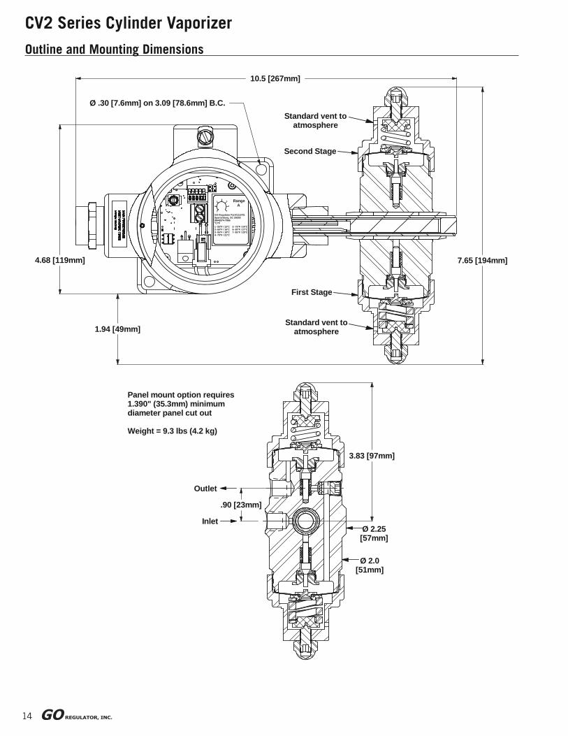
Outline and Mounting Dimensions
.90 [23mm]
Inlet
Panel mount option requires 1.390" (35.3mm) minimum diameter panel cut out
Weight = 9.3 lbs (4.2 kg)
Outlet
3.83 [97mm]
Ø 2.25 [57mm]
Ø 2.0 [51mm]
1.94 [49mm]
10.5 [267mm]
1- 55°F / 13°C 5- 75°F / 24°C2- 60°F / 16°C 6- 80°F / 27°C3- 65°F / 18°C 7- 85°F / 29°C4- 70°F / 21°C
RangeA
453
1
6
7
2
GO Regulator Part#115791Spartanburg, SC 29303(864)574-7966°C/°F
4.68 [119mm]
Ø .30 [7.6mm] on 3.09 [78.6mm] B.C.
7.65 [194mm]
First Stage
Standard vent to atmosphere
Second Stage
Standard vent to atmosphere
pre
ssure
regula
tors
15
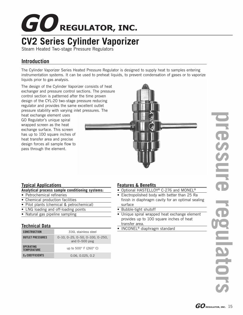
CV2 Series Cylinder VaporizerSteam Heated Two-stage Pressure Regulators
Features & Benefi ts• Optional HASTELLOY® C-276 and MONEL®
• Electropolished body with better than 25 Ra
fi nish in diaphragm cavity for an optimal sealing
surface
• Bubble-tight shutoff
• Unique spiral wrapped heat exchange element
provides up to 100 square inches of heat
transfer area.
• INCONEL® diaphragm standard
Introduction
The Cylinder Vaporizer Series Heated Pressure Regulator is designed to supply heat to samples entering
instrumentation systems. It can be used to preheat liquids, to prevent condensation of gases or to vaporize
liquids prior to gas analysis.
The design of the Cylinder Vaporizer consists of heat
exchanger and pressure control sections. The pressure
control section is patterned after the time proven
design of the CYL-20 two-stage pressure reducing
regulator and provides the same excellent outlet
pressure stability with varying inlet pressures. The
heat exchange element uses
GO Regulator’s unique spiral
wrapped screen as the heat
exchange surface. This screen
has up to 100 square inches of
heat transfer area and precise
design forces all sample fl ow to
pass through the element.
Typical ApplicationsAnalytical process sample conditioning systems:
• Petrochemical refi neries
• Chemical production facilities
• Pilot plants (chemical & petrochemical)
• LNG loading and off-loading points
• Natural gas pipeline sampling
CONSTRUCTION 316L stainless steel
OUTLET PRESSURES 0–10, 0–25, 0–50, 0–100, 0–250,
and 0–500 psig
OPERATING TEMPERATURE
up to 500° F (260° C)
CV COEFFICIENTS 0.06, 0.025, 0.2
Technical Data

16
CV2 Series Cylinder Vaporizer
How to Order
Maximum Temperature & Operating Inlet PressuresSEAT MATERIAL MAXIMUM TEMPERATURE @ MAXIMUM OPERATING INLET PRESSURE
Up to 380° F (193° C) @ 400 psig (2.76 MPa)
PEEK™ Up to 380° F (193° C) @ 6000 psig (41.37 MPa)
Standard items in bold
Tefzel® Ceramic Filled PTFE & PCTFE
2nd Stage1st Stage
CV2 – 1 A 1 Q 3 1 Q 3 G 1 5 5 5 5 5BODY MATERIAL
1 316L stainless steel,
stainless steel diaphragm
4 MONEL®, INCONEL®
diaphragm
6 HASTELLOY® C,
INCONEL® diaphragm
C 316L stainless steel,
INCONEL® diaphragm
PORT CONFIGURATION
A Standard Body "A" (One inlet
Port and One Outlet Port)
For more confi gurations,
see pages 47-48
PROCESS PORT TYPE
0 1⁄8" FNPT
1 1⁄4" FNPT
SEAT MATERIAL (1ST STAGE)
A Tefzel®
B Ceramic Filled PTFE
H PCTFE
Q PEEK™
FLOW COEFFICIENT (CV) (1ST STAGE)
C 0.025
3 0.06
5 0.2
CAP ASSEMBLY (1ST STAGE)
1 Tamper-proof, stainless steel
4 Tamper-proof, panel mount, stainless steel
7 Tamper-proof, captured vent, stainless steel
SEAT MATERIAL (2ND STAGE)
A Tefzel®
B Ceramic Filled PTFE
H PCTFE
Q PEEK™
FLOW COEFFICIENT (CV) (2ND STAGE)
C 0.025
3 0.06
5 0.2
OPTIONSB EB-5 cleaningD Helium Leak TestE Pressure Test Certifi cateF Certifi cate of ConformityG CMTR
VOLTAGE5 Steam
THERMISTOR TYPE5 Steam
CONTROLLER TYPE5 Steam
HEATER WATTAGE5 Steam
TEMPERATURE RANGE5 Steam
CAP ASSEMBLY (2ND STAGE)1 Tamper-proof, stainless
steel4 Tamper-proof, panel
mount, stainless steel7 Tamper-proof, captured
vent, stainless steel
OUTPUT RANGE (2ND STAGE)C 0–10 psigD 0–25 psigE 0–50 psigG 0–100 psigI 0–250 psigJ 0–500 psig
To Order, contact your local Distributor Link below:
www.goreg.com/distributor/index.htmVerify that your chosen part number is valid using the GO Wizards at
www.goreg.com/products/matrix/index.htm
NOTE: Contact the factory for any additional requirements.
17
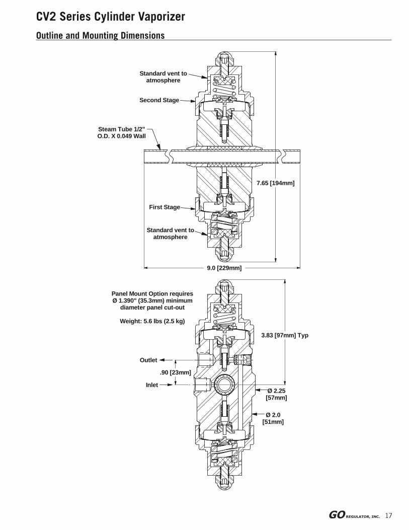
CV2 Series Cylinder Vaporizer
Outline and Mounting Dimensions
Steam Tube 1/2" O.D. X 0.049 Wall
7.65 [194mm]
Outlet
InletØ 2.25 [57mm]
Standard vent to atmosphere
Ø 2.0 [51mm]
First Stage
Panel Mount Option requires Ø 1.390" (35.3mm) minimum
diameter panel cut-out
Weight: 5.6 lbs (2.5 kg)
9.0 [229mm]
.90 [23mm]
3.83 [97mm] Typ
Standard vent to atmosphere
Second Stage
pre
ssure
regula
tors
18
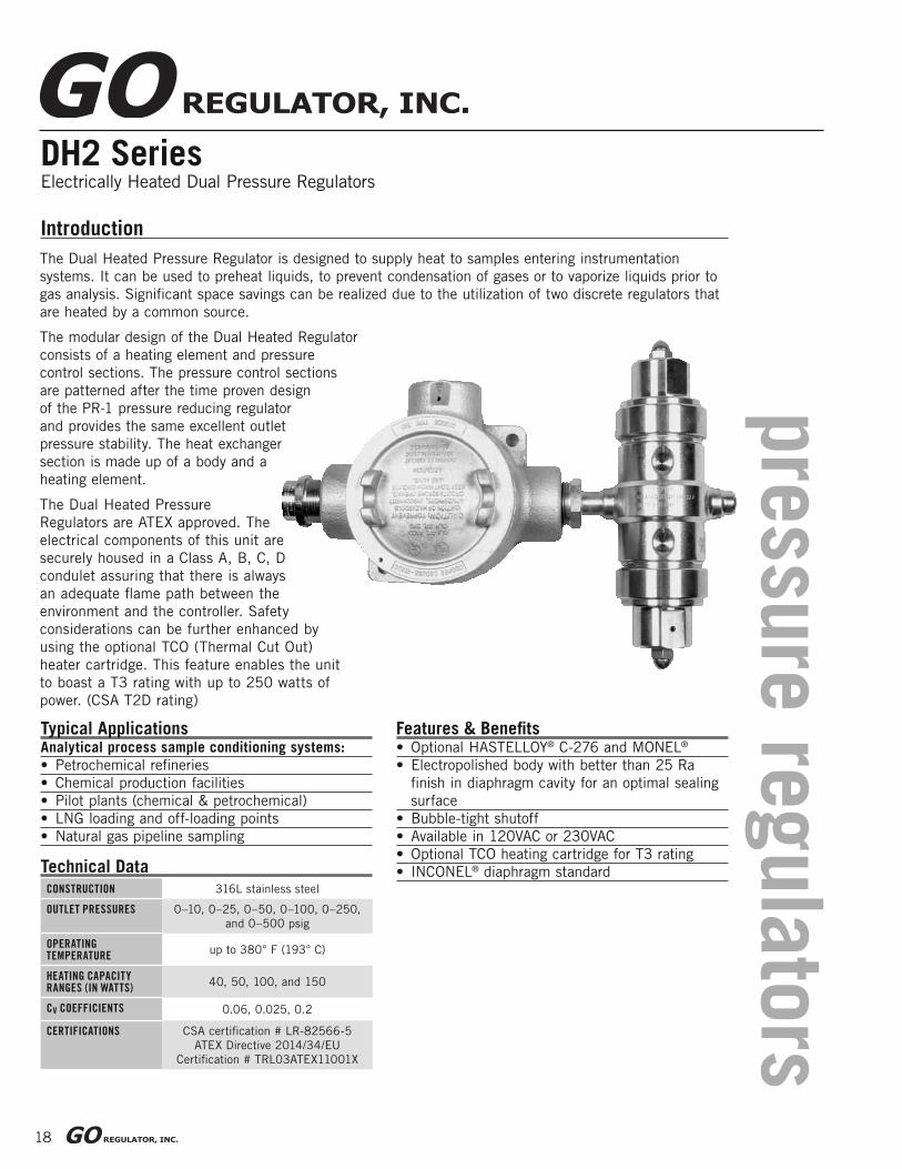
DH2 SeriesElectrically Heated Dual Pressure Regulators
Features & Benefi ts• Optional HASTELLOY® C-276 and MONEL®
• Electropolished body with better than 25 Ra
fi nish in diaphragm cavity for an optimal sealing
surface
• Bubble-tight shutoff
• Available in 120VAC or 230VAC
• Optional TCO heating cartridge for T3 rating
• INCONEL® diaphragm standard
Introduction
The Dual Heated Pressure Regulator is designed to supply heat to samples entering instrumentation
systems. It can be used to preheat liquids, to prevent condensation of gases or to vaporize liquids prior to
gas analysis. Signifi cant space savings can be realized due to the utilization of two discrete regulators that
are heated by a common source.
The modular design of the Dual Heated Regulator
consists of a heating element and pressure
control sections. The pressure control sections
are patterned after the time proven design
of the PR-1 pressure reducing regulator
and provides the same excellent outlet
pressure stability. The heat exchanger
section is made up of a body and a
heating element.
The Dual Heated Pressure
Regulators are ATEX approved. The
electrical components of this unit are
securely housed in a Class A, B, C, D
condulet assuring that there is always
an adequate fl ame path between the
environment and the controller. Safety
considerations can be further enhanced by
using the optional TCO (Thermal Cut Out)
heater cartridge. This feature enables the unit
to boast a T3 rating with up to 250 watts of
power. (CSA T2D rating)
Typical ApplicationsAnalytical process sample conditioning systems:
• Petrochemical refi neries
• Chemical production facilities
• Pilot plants (chemical & petrochemical)
• LNG loading and off-loading points
• Natural gas pipeline sampling
CONSTRUCTION 316L stainless steel
OUTLET PRESSURES 0–10, 0–25, 0–50, 0–100, 0–250,
and 0–500 psig
OPERATING TEMPERATURE
up to 380° F (193° C)
HEATING CAPACITY RANGES (IN WATTS)
40, 50, 100, and 150
CV COEFFICIENTS 0.06, 0.025, 0.2
CERTIFICATIONS CSA certifi cation # LR-82566-5
ATEX Directive 2014/34/EU
Certifi cation # TRL03ATEX11001X
Technical Data
19
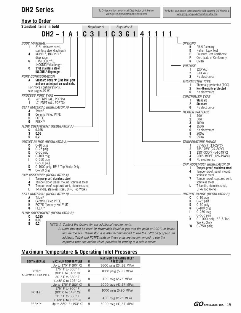
DH2 Series
Regulator A Regulator B
How to Order
DH2 – 1 A 1 C 3 I 1 C 3 G 1 4 1 1 1 1BODY MATERIAL
1 316L stainless steel,stainless steel diaphragm
4 MONEL®, INCONEL®
diaphragm6 HASTELLOY® C, INCONEL® diaphragmC 316L stainless steel
INCONEL® diaphragm
PORT CONFIGURATIONA Standard Body "A" (One inlet port
and one outlet port on each side.For more confi gurations,see pages 49-51
PROCESS PORT TYPE0 1⁄8" FNPT (ALL PORTS)1 1⁄4" FNPT (ALL PORTS)
SEAT MATERIAL (REGULATOR A)A Tefzel®
B Ceramic Filled PTFEH PCTFEQ PEEK™
FLOW COEFFICIENT (REGULATOR A)C 0.0253 0.065 0.2
OUTLET RANGE (REGULATOR A)C 0–10 psigD 0–25 psigE 0–50 psigG 0–100 psigI 0–250 psigJ 0–500 psigK 0–1000 psig, BP-6 Top Works OnlyW 0–750 psig
CAP ASSEMBLY (REGULATOR A)1 Tamper-proof, stainless steel4 Tamper-proof, panel mount, stainless steel7 Tamper-proof, captured vent, stainless steelL T-handle, stainless steel, BP-6 Top Works
SEAT MATERIAL (REGULATOR B)A Tefzel®
B Ceramic Filled PTFEH PCTFE (formerly Kel-F® 81)Q PEEK™
FLOW COEFFICIENT (REGULATOR B)C 0.0253 0.065 0.2
OPTIONSB EB-5 CleaningD Helium Leak TestE Pressure Test Certifi cateF Certifi cate of ConformityG CMTR
VOLTAGE1 120 VAC2 230 VAC2 No electronics
THERMISTOR TYPE1 Thermally protected (TCO)2 Non-thermally protected6 No electronics
CONTROLLER TYPE1 Standard2 Standard6 No electronics
HEATER WATTAGE1 40W2 50W3 100W4 150W6 No electronics8 200W9 250W
TEMPERATURE RANGE1 55°-85°F (13-29°C)2 75°-175°F (24-80°C)3 130°-300°F (54-149°C)4 260°-380°F (126-194°C)6 No electronics
CAP ASSEMBLY (REGULATOR B)1 Tamper-proof, stainless steel4 Tamper-proof, panel mount,
stainless steel7 Tamper-proof, captured vent,
stainless steelL T-handle, stainless steel,
BP-6 Top Works
OUTPUT RANGE (REGULATOR B)C 0–10 psigD 0–25 psigE 0–50 psigG 0–100 psigI 0–250 psigJ 0–500 psigK 0–1000 psig, BP-6 Top Works OnlyW 0–750 psig
Maximum Temperature & Operating Inlet Pressures
SEAT MATERIAL MAXIMUM TEMPERATURE @MAXIMUM OPERATING INLET
PRESSURE
Tefzel®
& Ceramic Filled PTFE
Up to 175° F (80° C) @ 3600 psig (24.82 MPa)
176° F to 300° F
(80° C to 148° C)@ 1000 psig (6.90 MPa)
301° F to 380° F
(148° C to 193° C)@ 400 psig (2.76 MPa)
PCTFE
Up to 175° F (80° C) @ 6000 psig (41.37 MPa)
176° F to 300° F
(80° C to 148° C)@ 1000 psig (6.90 MPa)
301° F to 380° F
(148° C to 193° C)@ 400 psig (2.76 MPa)
PEEK™ Up to 380° F (193° C) @ 6000 psig (41.37 MPa)
Standard items in bold
To Order, contact your local Distributor Link below:
www.goreg.com/distributor/index.htmVerify that your chosen part number is valid using the GO Wizards at
www.goreg.com/products/matrix/index.htm
NOTE: 1. Contact the factory for any additional requirements.
2. Units that will be used for fl ammable liquid or gas with fi re point at 200°C or below
require the TCO Thermistor. It is also recommended to use the 1-PC body option. In
addition, Tefzel and PCTFE seats in these units are recommended to use the
captured vent cap option which provides for venting to a safe location.
20
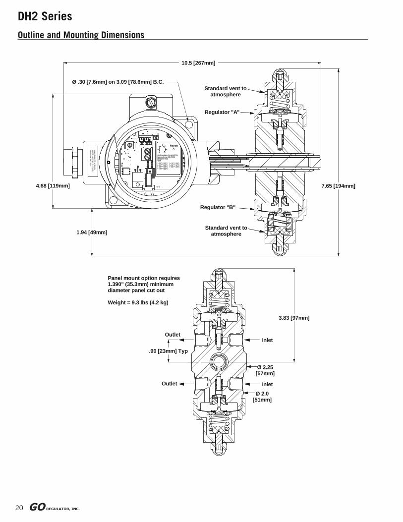
DH2 Series
Outline and Mounting Dimensions
.90 [23mm] Typ
Outlet
Panel mount option requires 1.390" (35.3mm) minimum diameter panel cut out
Weight = 9.3 lbs (4.2 kg)
Outlet
3.83 [97mm]
Inlet
Ø 2.25 [57mm]
Ø 2.0 [51mm]
Inlet
1.94 [49mm]
10.5 [267mm]
MA
IN PO
WE
R W
IRIN
GM
US
T HA
VE
85°C (185°F)
MIN
IMU
M R
ATIN
G 1- 55°F / 13°C 5- 75°F / 24°C2- 60°F / 16°C 6- 80°F / 27°C3- 65°F / 18°C 7- 85°F / 29°C4- 70°F / 21°C
1
4
6
7
53
2
RangeA
GO Regulator Part#115791Spartanburg, SC 29303(864)574-7966°C/°F
4.68 [119mm]
Ø .30 [7.6mm] on 3.09 [78.6mm] B.C.
7.65 [194mm]
Regulator "B"
Standard vent to atmosphere
Regulator "A"
Standard vent to atmosphere

pre
ssure
regula
tors
21
DH2 SeriesSteam Heated Dual Pressure Regulators
Features & Benefi ts• Optional HASTELLOY® C-276 and MONEL®
• Electropolished body with better than 25 Ra
fi nish in diaphragm cavity for an optimal sealing
surface
• Bubble-tight shutoff
• Modular pressure control and heat
exchanger assemblies for easy maintenance
• INCONEL® diaphragm standard
Introduction
Typical ApplicationsAnalytical process sample conditioning systems:
• Petrochemical refi neries
• Chemical production facilities
• Pilot plants (chemical & petrochemical)
• LNG loading and off-loading points
• Natural gas pipeline sampling
CONSTRUCTION 316L stainless steel
OUTLET PRESSURES 0–10, 0–25, 0–50, 0–100, 0–250,
0–500, 0–750, and 0–1000 psig
OPERATING TEMPERATURE
up to 500° F (260° C)
CV COEFFICIENTS 0.06, 0.025, 0.2
Technical Data
The Dual Heated Pressure Regulator is designed to supply heat to samples entering instrumentation
systems. It can be used to preheat liquids, to prevent condensation of gases or to vaporize liquids prior to
gas analysis. Signifi cant space savings can be realized due to the utilization of two discrete regulators that
are heated by a common source.
The modular design of the Dual Heated Regulator
consists of a heating element and pressure control
sections. The pressure control sections are patterned
after the time-proven design of the PR-1 pressure
reducing regulator and provides the same excellent outlet
pressure stability. The heat exchanger section is made
up a body and a heating element.
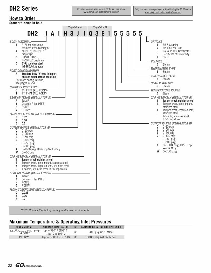
22
DH2 Series
How to Order
Maximum Temperature & Operating Inlet PressuresSEAT MATERIAL MAXIMUM TEMPERATURE @ MAXIMUM OPERATING INLET PRESSURE
Up to 380° F (193° C)
(148° C to 193° C)@ 400 psig (2.76 MPa)
PEEK™ Up to 380° F (193° C) @ 6000 psig (41.37 MPa)
Standard items in boldRegulator A Regulator B
DH2 – 1 A 1 H 3 J 1 Q 3 E 1 5 5 5 5 5BODY MATERIAL
1 316L stainless steel,stainless steel diaphragm
4 MONEL®, INCONEL®
diaphragm6 HASTELLOY® C, INCONEL® diaphragmC 316L stainless steel
INCONEL® diaphragm
PORT CONFIGURATIONA Standard Body "A" (One inlet port
and one outlet port on each side.For more confi gurations,see pages 49-51
PROCESS PORT TYPE0 1⁄8" FNPT (ALL PORTS)1 1⁄4" FNPT (ALL PORTS)
SEAT MATERIAL (REGULATOR A)A Tefzel®
B Ceramic Filled PTFEH PCTFEQ PEEK™
FLOW COEFFICIENT (REGULATOR A)C 0.0253 0.065 0.2
OUTLET RANGE (REGULATOR A)C 0–10 psigD 0–25 psigE 0–50 psigG 0–100 psigI 0–250 psigJ 0–500 psigK 0–1000 psig, BP-6 Top Works OnlyW 0–750 psig
CAP ASSEMBLY (REGULATOR A)1 Tamper-proof, stainless steel4 Tamper-proof, panel mount, stainless steel7 Tamper-proof, captured vent, stainless steelL T-handle, stainless steel, BP-6 Top Works
SEAT MATERIAL (REGULATOR B)A Tefzel®
B Ceramic Filled PTFEH PCTFEQ PEEK™
FLOW COEFFICIENT (REGULATOR B)C 0.0253 0.065 0.2
OPTIONSB EB-5 CleaningD Helium Leak TestE Pressure Test Certifi cateF Certifi cate of ConformityG CMTR
VOLTAGE5 Steam
THERMISTOR TYPE5 Steam
CONTROLLER TYPE5 Steam
HEATER WATTAGE5 Steam
TEMPERATURE RANGE5 Steam
CAP ASSEMBLY (REGULATOR B)1 Tamper-proof, stainless steel4 Tamper-proof, panel mount,
stainless steel7 Tamper-proof, captured vent,
stainless steelL T-handle, stainless steel,
BP-6 Top Works
OUTPUT RANGE (REGULATOR B)C 0–10 psigD 0–25 psigE 0–50 psigG 0–100 psigI 0–250 psigJ 0–500 psigK 0–1000 psig, BP-6 Top Works OnlyW 0–750 psig
To Order, contact your local Distributor Link below:
www.goreg.com/distributor/index.htmVerify that your chosen part number is valid using the GO Wizards at
www.goreg.com/products/matrix/index.htm
NOTE: Contact the factory for any additional requirements.
Tefzel®,Ceramic Filled PTFE, & PCTFE
23
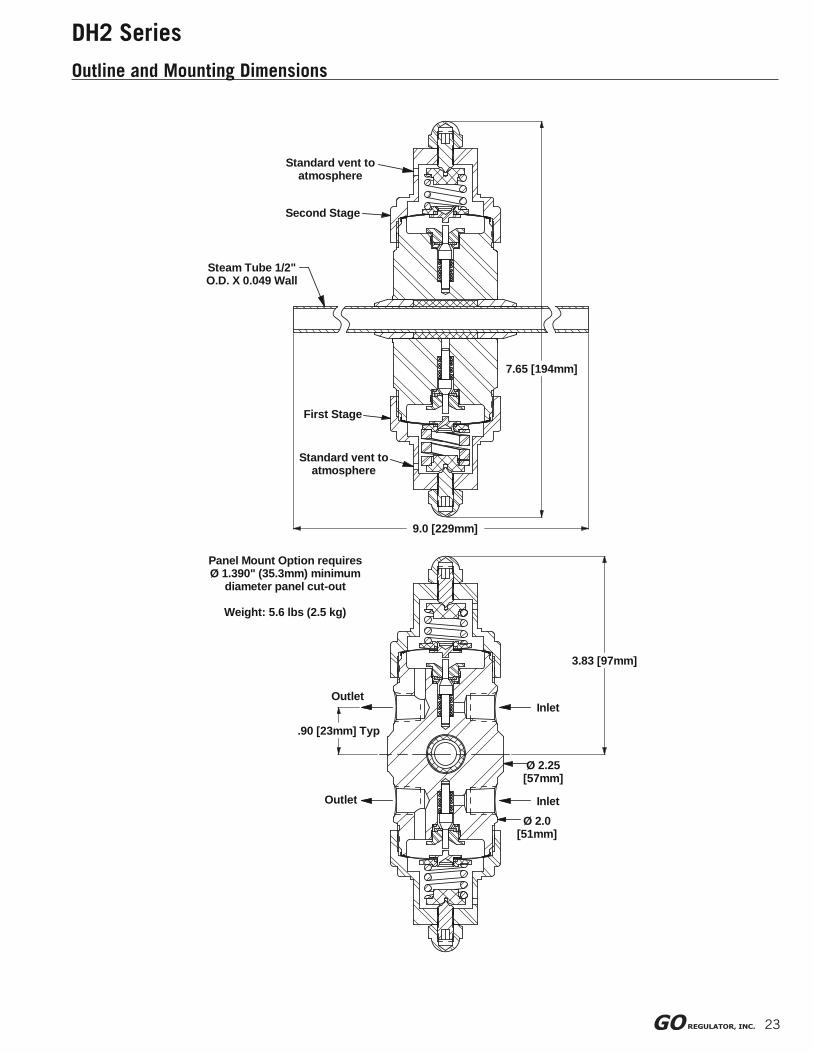
DH2 Series
Outline and Mounting Dimensions
Steam Tube 1/2" O.D. X 0.049 Wall
7.65 [194mm]
Standard vent to atmosphere
Outlet
Ø 2.25 [57mm]
First Stage
Ø 2.0 [51mm]
Outlet Inlet
Inlet
Panel Mount Option requiresØ 1.390" (35.3mm) minimum
diameter panel cut-out
Weight: 5.6 lbs (2.5 kg)
3.83 [97mm]
9.0 [229mm]
.90 [23mm] Typ
Standard vent to atmosphere
Second Stage

pre
ssure
regula
tors
24
MV-2 SeriesMiniature Vaporizing Pressure Regulator
The MV-2 Series Miniature Vaporizing Regulator
is one of the smallest envelopes in the industry.
Weighing in at a scant 0.86 pounds, the MV-2
is designed to supply heat to samples entering
instrumentation systems where space is at a
premium and quality cannot be compromised.
It can be used to preheat liquids, to prevent
condensation of gases or to vaporize liquids
prior to gas analysis.
The pressure control section of the MV-2 is
patterned after the time-tested design of our
CPR-1 and provides the same excellent outlet
pressure stability. The heating plate utilizes
GO Regulator’s unique heating element and
incorporates an optional Thermal Cutout
Device (TCO). This device prevents any
exposed surface of the unit from exceeding
200° C under normal or fault conditions
and is exclusive to GO Regulator’s line of
electrically heated vaporizing regulators.
Offered in both 12 VDC and 24 VDC, the
MV-2 Series offers the utmost in unequalled
system safety and performance.
Features & Benefi ts• Electro polished body with better than 25 Ra
fi nish in diaphragm cavity for an optimal sealing
surface
• Bubble-tight shutoff
• Unique Spiro-Wind heating element provides
exceptionally even heating
• Available in 12 VDC and 24 VDC
• Optional TCO heating cartridge
Introduction
Typical ApplicationsAnalytical process sample conditioning systems:
• Petrochemical refi neries
• Chemical production facilities
• Pilot plants (chemical & petrochemical)
• Portable low voltage analyzers
CONSTRUCTION 316L stainless steel
OUTLET PRESSURES 0–10, 0–25, 0–50, 0–100, 0–250,
and 0–500 psig
OPERATING TEMPERATURE
up to 380° F (193° C)
HEATING CAPACITY RANGES (IN WATTS)
40 and 100
Technical Data

25
MV-2 Series
How to Order
MV2 – 1 A B 2 3 B 3 E H D 1
BODY MATERIAL
1 316L stainless steel
4 MONEL®
PORT CONFIGURATION
A Standard
For more confi gurations, see page 46
PORT TYPE
0 1⁄8˝ FNPT (all ports)
A 1⁄16˝ FNPT (all ports)
B 1⁄8˝ FNPT inlets; 1⁄16˝ FNPT outlets
TEMPERATURE RANGE
1 55°-85°F (13-29°C)
2 75°-175°F (24-80°C)
3 130°-300°F (54-149°C)
4 260°-380°F (126-194°C)
0 No electronics
HEATER WATTAGE
1 40W
2 40W with thermal cutout (TCO)
3 100W
4 100W with thermal cutout (TCO)
0 No electronics
HEATER VOLTAGE
B 12 VDC
C 24 VDC
0 No electronics
OPTIONS (NOT REQUIRED)
B EB5 cleaning
D Helium leak test
E Pressure test certifi cate
F Certifi cate of Conformity
G CMTR
CAP STYLE
1 Tamper-proof, stainless steel
4 Tamper-proof, panel mount,
stainless steel
CAVITY O-RING MATERIAL
D Viton®
I PTFE
SEAT MATERIAL
A Tefzel®
H PCTFE
Q PEEK™
OUTPUT RANGE
C 0–10 psig
D 0–25 psig
E 0–50 psig
G 0–100 psig
I 0–250 psig
J 0–500 psig
FLOW COEFFICIENT (Cv)
3 0.06
C 0.025
Maximum Temperature & Operating Inlet Pressures
SEAT MATERIAL MAXIMUM TEMPERATURE @MAXIMUM OPERATING INLET
PRESSURE
Tefzel®
& PCTFE
Up to 175° F (80° C) @ 3600 psig (24.82 MPa)
176° F to 300° F
(80° C to 148° C)@ 1000 psig (6.90 MPa)
301° F to 380° F
(148° C to 193° C)@ 400 psig (2.76 MPa)
PEEK™ Up to 380° F (193° C) @ 3600 psig (24.82 MPa)
Standard items in bold
NOTE: Contact the factory for any additional requirements.
To Order, contact your local Distributor Link below:
www.goreg.com/distributor/index.htmVerify that your chosen part number is valid using the GO Wizards at
www.goreg.com/products/matrix/index.htm
26
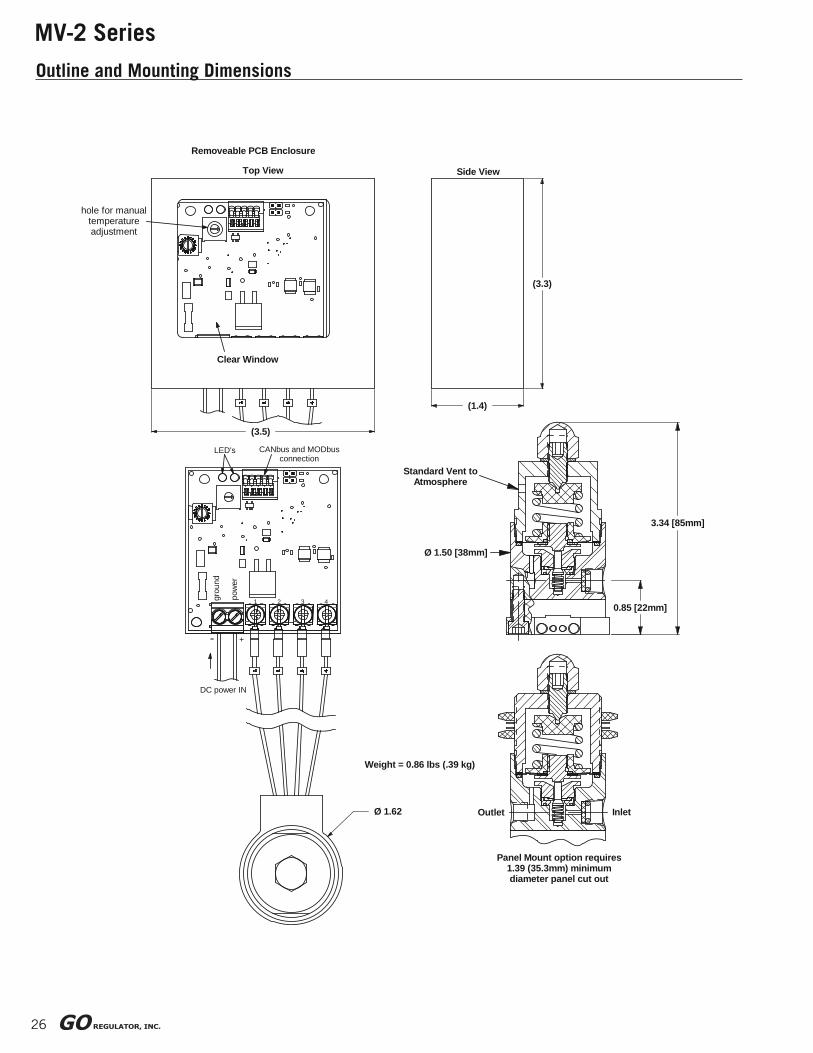
MV-2 Series
Outline and Mounting Dimensions
3.34 [85mm]
Weight = 0.86 lbs (.39 kg)
Ø 1.62
DC power IN
pow
er
-
grou
nd
+
321 4
Panel Mount option requires 1.39 (35.3mm) minimum diameter panel cut out
Outlet Inlet
Ø 1.50 [38mm]
0.85 [22mm]
LED's
Clear Window
(3.5)
CANbus and MODbus connection
Top View
Removeable PCB Enclosure
hole for manual temperature adjustment
(3.3)
Standard Vent to Atmosphere
(1.4)
Side View
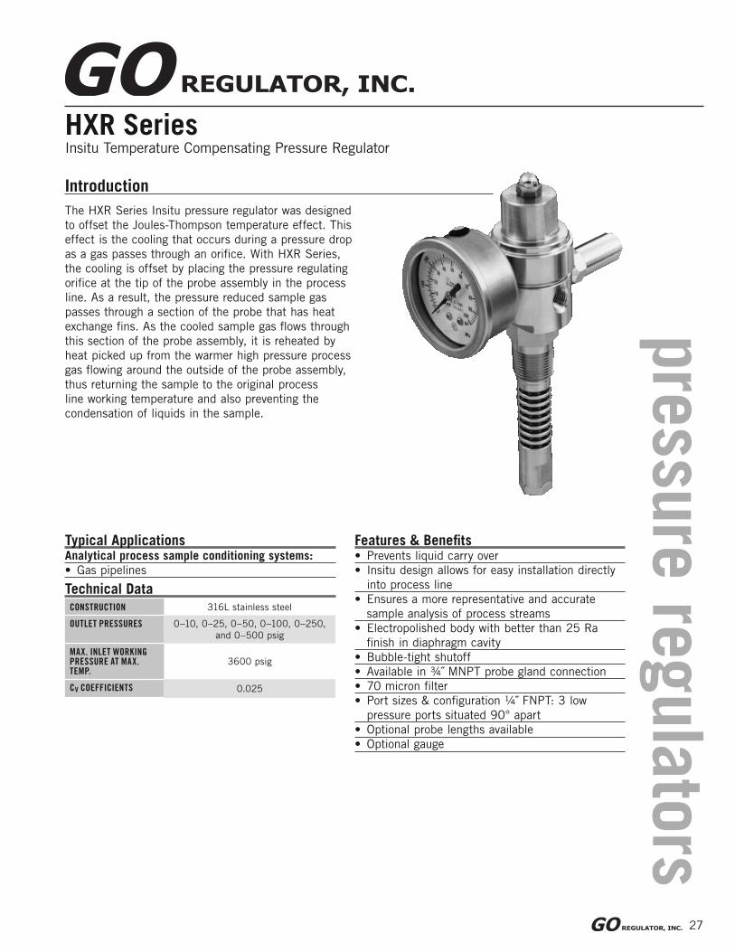
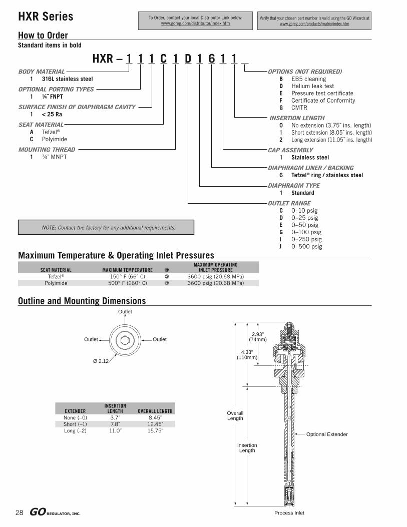
HXR SeriesInsitu Temperature Compensating Pressure Regulator
The HXR Series Insitu pressure regulator was designed
to offset the Joules-Thompson temperature effect. This
effect is the cooling that occurs during a pressure drop
as a gas passes through an orifi ce. With HXR Series,
the cooling is offset by placing the pressure regulating
orifi ce at the tip of the probe assembly in the process
line. As a result, the pressure reduced sample gas
passes through a section of the probe that has heat
exchange fi ns. As the cooled sample gas fl ows through
this section of the probe assembly, it is reheated by
heat picked up from the warmer high pressure process
gas fl owing around the outside of the probe assembly,
thus returning the sample to the original process
line working temperature and also preventing the
condensation of liquids in the sample.
Features & Benefi ts• Prevents liquid carry over
• Insitu design allows for easy installation directly
into process line
• Ensures a more representative and accurate
sample analysis of process streams
• Electropolished body with better than 25 Ra
fi nish in diaphragm cavity
• Bubble-tight shutoff
• Available in ¾˝ MNPT probe gland connection
• 70 micron fi lter
• Port sizes & confi guration ¼˝ FNPT: 3 low
pressure ports situated 90° apart
• Optional probe lengths available
• Optional gauge
Typical ApplicationsAnalytical process sample conditioning systems:
• Gas pipelines
Introduction
CONSTRUCTION 316L stainless steel
OUTLET PRESSURES 0–10, 0–25, 0–50, 0–100, 0–250,
and 0–500 psig
MAX. INLET WORKING PRESSURE AT MAX. TEMP.
3600 psig
CV COEFFICIENTS 0.025
Technical Data
pre
ssure
regula
tors
27
28
HXR Series
InsertionLength
Process Inlet
4.33"(110mm)
2.93"(74mm)
OverallLength
Ø 2.12
Optional Extender
OutletOutlet
Outlet
How to Order
HXR – 1 1 1 C 1 D 1 6 1 1BODY MATERIAL
1 316L stainless steel
OPTIONAL PORTING TYPES
1 ¼˝ FNPT
SURFACE FINISH OF DIAPHRAGM CAVITY
1 < 25 Ra
SEAT MATERIAL
A Tefzel®
C Polyimide
MOUNTING THREAD
1 ¾˝ MNPT
OPTIONS (NOT REQUIRED)
B EB5 cleaning
D Helium leak test
E Pressure test certifi cate
F Certifi cate of Conformity
G CMTR
INSERTION LENGTH
0 No extension (3.75˝ ins. length)
1 Short extension (8.05˝ ins. length)
2 Long extension (11.05˝ ins. length)
CAP ASSEMBLY
1 Stainless steel
DIAPHRAGM LINER / BACKING
6 Tefzel® ring / stainless steel
DIAPHRAGM TYPE
1 Standard
OUTLET RANGE
C 0–10 psig
D 0–25 psig
E 0–50 psig
G 0–100 psig
I 0–250 psig
J 0–500 psig
Maximum Temperature & Operating Inlet Pressures
SEAT MATERIAL MAXIMUM TEMPERATURE @MAXIMUM OPERATING
INLET PRESSURE
Tefzel® 150° F (66° C) @ 3600 psig (20.68 MPa)
Polyimide 500° F (260° C) @ 3600 psig (20.68 MPa)
Outline and Mounting Dimensions
EXTENDERINSERTION
LENGTH OVERALL LENGTH
None (–0) 3.7˝ 8.45˝
Short (–1) 7.8˝ 12.45˝
Long (–2) 11.0˝ 15.75˝
Standard items in bold
To Order, contact your local Distributor Link below:
www.goreg.com/distributor/index.htmVerify that your chosen part number is valid using the GO Wizards at
www.goreg.com/products/matrix/index.htm
NOTE: Contact the factory for any additional requirements.
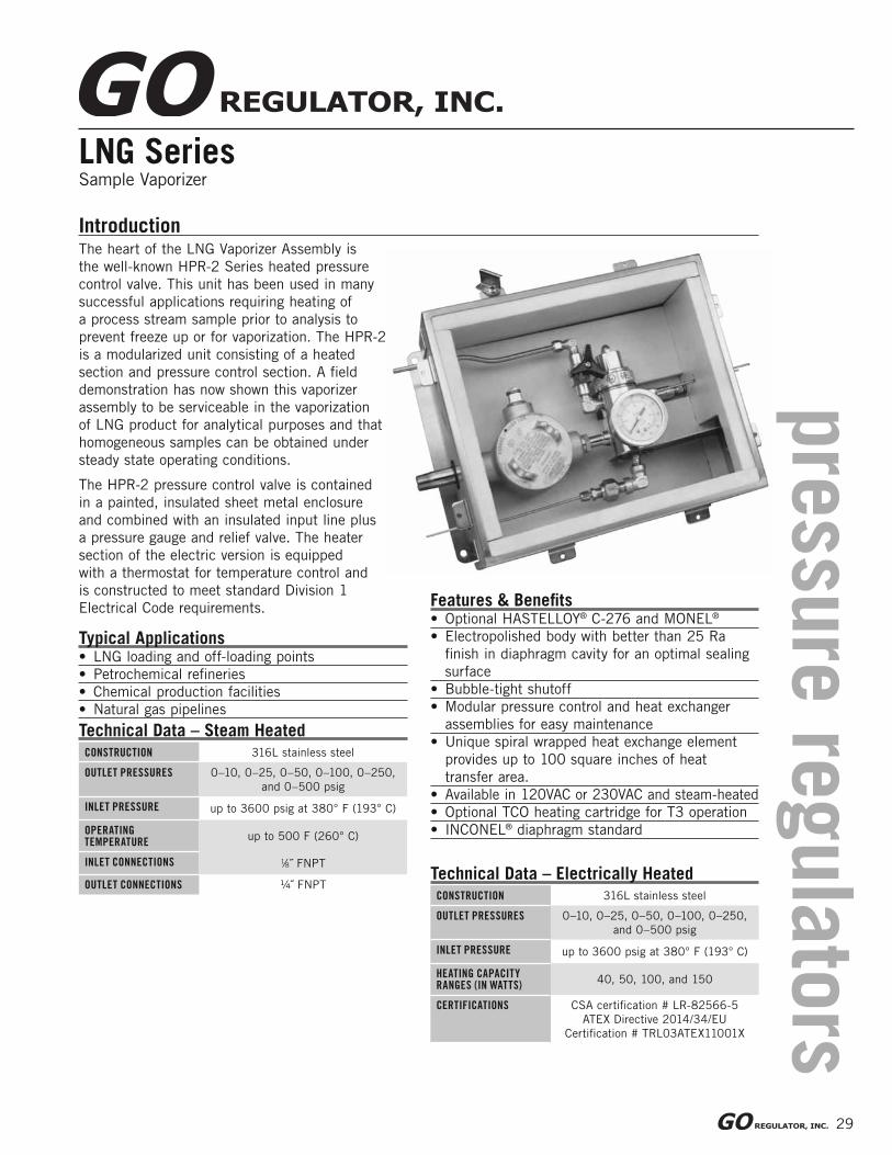
LNG SeriesSample Vaporizer
The heart of the LNG Vaporizer Assembly is
the well-known HPR-2 Series heated pressure
control valve. This unit has been used in many
successful applications requiring heating of
a process stream sample prior to analysis to
prevent freeze up or for vaporization. The HPR-2
is a modularized unit consisting of a heated
section and pressure control section. A fi eld
demonstration has now shown this vaporizer
assembly to be serviceable in the vaporization
of LNG product for analytical purposes and that
homogeneous samples can be obtained under
steady state operating conditions.
The HPR-2 pressure control valve is contained
in a painted, insulated sheet metal enclosure
and combined with an insulated input line plus
a pressure gauge and relief valve. The heater
section of the electric version is equipped
with a thermostat for temperature control and
is constructed to meet standard Division 1
Electrical Code requirements.
Introduction
Features & Benefi ts• Optional HASTELLOY® C-276 and MONEL®
• Electropolished body with better than 25 Ra
fi nish in diaphragm cavity for an optimal sealing
surface
• Bubble-tight shutoff
• Modular pressure control and heat exchanger
assemblies for easy maintenance
• Unique spiral wrapped heat exchange element
provides up to 100 square inches of heat
transfer area.
• Available in 120VAC or 230VAC and steam-heated
• Optional TCO heating cartridge for T3 operation
• INCONEL® diaphragm standard
Typical Applications• LNG loading and off-loading points
• Petrochemical refi neries
• Chemical production facilities
• Natural gas pipelines
CONSTRUCTION 316L stainless steel
OUTLET PRESSURES 0–10, 0–25, 0–50, 0–100, 0–250,
and 0–500 psig
INLET PRESSURE up to 3600 psig at 380° F (193° C)
HEATING CAPACITY RANGES (IN WATTS)
40, 50, 100, and 150
CERTIFICATIONS CSA certifi cation # LR-82566-5
ATEX Directive 2014/34/EU
Certifi cation # TRL03ATEX11001X
Technical Data – Electrically Heated
CONSTRUCTION 316L stainless steel
OUTLET PRESSURES 0–10, 0–25, 0–50, 0–100, 0–250,
and 0–500 psig
INLET PRESSURE up to 3600 psig at 380° F (193° C)
OPERATING TEMPERATURE
up to 500 F (260° C)
INLET CONNECTIONS 1⁄8˝ FNPT
OUTLET CONNECTIONS ¼˝ FNPT
Technical Data – Steam Heated
pre
ssure
regula
tors
29

30
LNG Series
How to Order
10283
BASIC PART NUMBER
102830 0–10 psig electronically heated, s.s diaphragm
102831 0–25 psig electroncially heated, s.s diaphragm
102832 0–50 psig electronically heated, s.s diaphragm
102833 0–100 psig electronically heated, s.s diaphragm
102834 0–250 psig electronically heated, s.s diaphragm
102835 0–500 psig electroncially heated, s.s diaphragm
109551 0–25 psig steam heated, s.s diaphragm
109552 0–50 psig steam heated, s.s diaphragm
109553 0–100 psig steam heated, s.s diaphragm
109554 0–250 psig steam heated, s.s diaphragm
109555 0–500 psig steam heated, s.s diaphragm
103680 0–10 psig electronically heated,
INCONEL® diaphragm
103681 0–25 psig electronically heated,
INCONEL® diaphragm
103682 0–50 psig electronically heated,
INCONEL® diaphragm
103683 0–100 psig electronically heated,
INCONEL® diaphragm
103684 0–250 psig electronically heated,
INCONEL® diaphragm
103685 0–500 psig electronically heated,
INCONEL® diaphragm
109561 0–25 psig steam heated, INCONEL® diaphragm
109562 0–50 psig steam heated, INCONEL® diaphragm
109563 0–100 psig steam heated, INCONEL® diaphragm
109564 0–250 psig steam heated, INCONEL® diaphragm
109565 0–500 psig steam heated, INCONEL® diaphragm
SEAT MATERIAL
A Tefzel®
B Ceramic Filled PTFE
H PCTFE
Q PEEK™
WATTAGE
1 40 watts
2 50 watts
3 100 watts
4 150 watts
5 Steam heated
8 200 watts
9 250 watts
OPTIONSB EB5 cleaningD Helium leak testE Pressure test certifi cateF Certifi cate of ConformityG CMTR
THERMISTOR TYPE1 Thermally protected (TCO)2 Non-thermally protected5 Steam
CONTROLLER TYPE1 Standard2 Standard5 Steam
CONFIGURATION1 Standard enclosure (painted steel)2 Stainless steel enclosure3 Standard enclosure,
all ¼˝ tube4 Stainless steel enclosure,
all ¼˝ tube5 Standard enclosure,
¼˝ tube bulkhead6 Stainless steel enclosure,
¼˝ tube bulkhead
HEATER BLOCK TYPE1 Steam2 Steam, HPR-2XW3 120 VAC4 230 VAC6 120 VAC, HPR-2XW7 230 VAC, HPR-2XW
TEMPERATURE RANGE1 55°-85°F (13-29°C)2 75°-175°F (24-80°C)3 130°-300°F (54-149°C)4 260°-380°F (126-194°C)5 Steam heated
Maximum Temperature & Operating Inlet Pressures
Standard items in bold
HPR-2 Electric
SEAT MATERIAL MAXIMUM TEMPERATURE @MAXIMUM OPERATING INLET
PRESSURE
Tefzel®
Ceramic Filled PTFE
& PCTFE
Up to 175° F (80° C) @ 3600 psig (24.82 MPa)
176° F to 300° F
(80° C to 148° C)@ 1000 psig (6.90 MPa)
301° F to 380° F
(148° C to 193° C)@ 400 psig (2.76 MPa)
PEEK™ Up to 380° F (193° C) @ 3600 psig (24.82 MPa)
HPR-2 Steam
SEAT MATERIALMAXIMUM
TEMPERATURE @MAXIMUM OPERATING INLET
PRESSURE
Up to 380° F (193° C) @ 400 psig (2.76 MPa)
PEEK™ Up to 380° F (193° C) @ 3600 psig (24.82 MPa)
How to Order
To Order, contact your local Distributor Link below:
www.goreg.com/distributor/index.htmVerify that your chosen part number is valid using the GO Wizards at
www.goreg.com/products/matrix/index.htm
Tefzel®
Ceramic Filled PTFE & PCTFE
LNG – C 2 3 3 1 2 2
NOTE: 1. Contact the factory for any additional requirements.
2. Units that will be used for fl ammable liquid or gas with fi re point at 200°C or below
require the TCO Thermistor. It is also recommended to use the 1-PC body option. In
addition, Tefzel and PCTFE seats in these units are recommended to use the
captured vent cap option which provides for venting to a safe location.
31
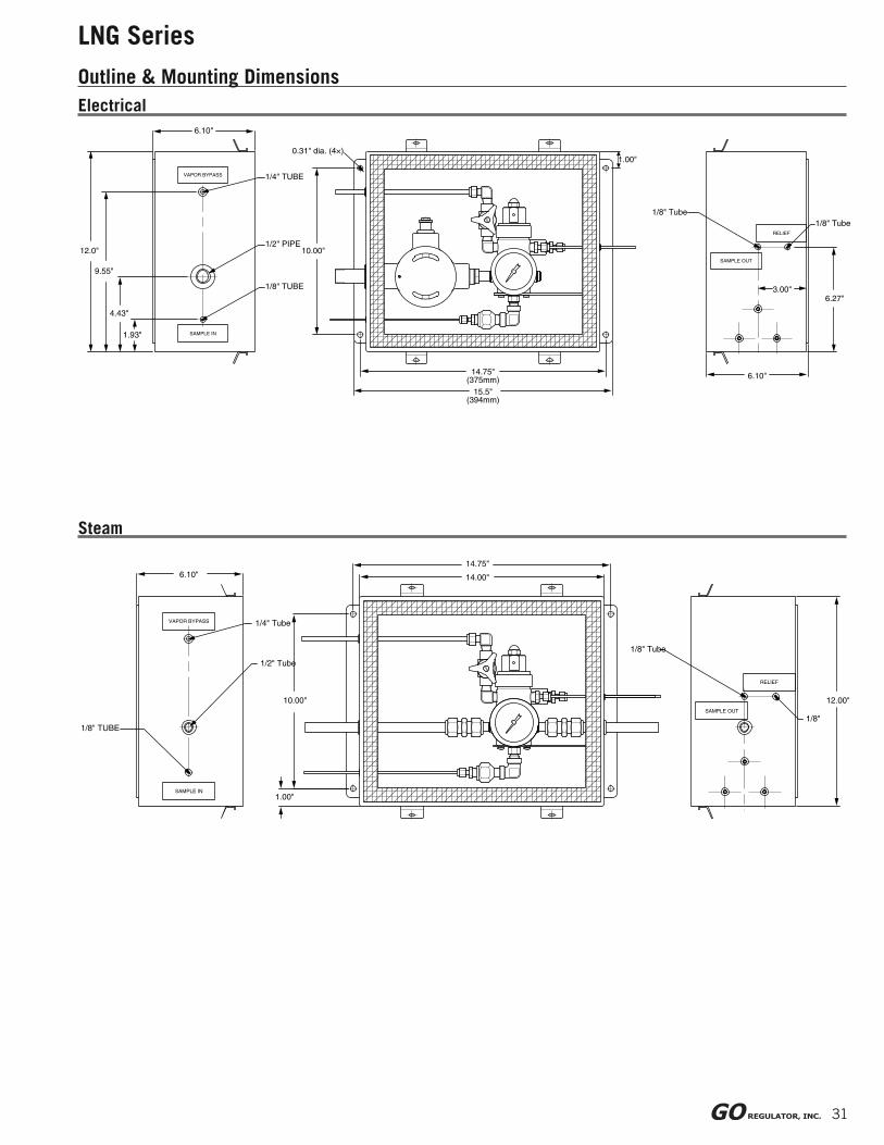
LNG Series
Outline & Mounting Dimensions
SAMPLE IN
VAPOR BYPASS
SAMPLE OUT
RELIEF
1/4" TUBE
1/2" PIPE
0.31" dia. (4×)
1/8" TUBE
6.10"
12.0"
6.27"
9.55"
4.43"
1.93"
10.00"
14.75"(375mm) 6.10"
3.00"
1.00"
15.5"(394mm)
1/8" Tube1/8" Tube
SAMPLE IN
VAPOR BYPASS
SAMPLE OUT
RELIEF
1/8"
6.10"
1.00"
1/4" Tube
1/8" Tube
12.00"
1/2" Tube
14.75"
10.00"
14.00"
1/8" TUBE
Electrical
Steam
32
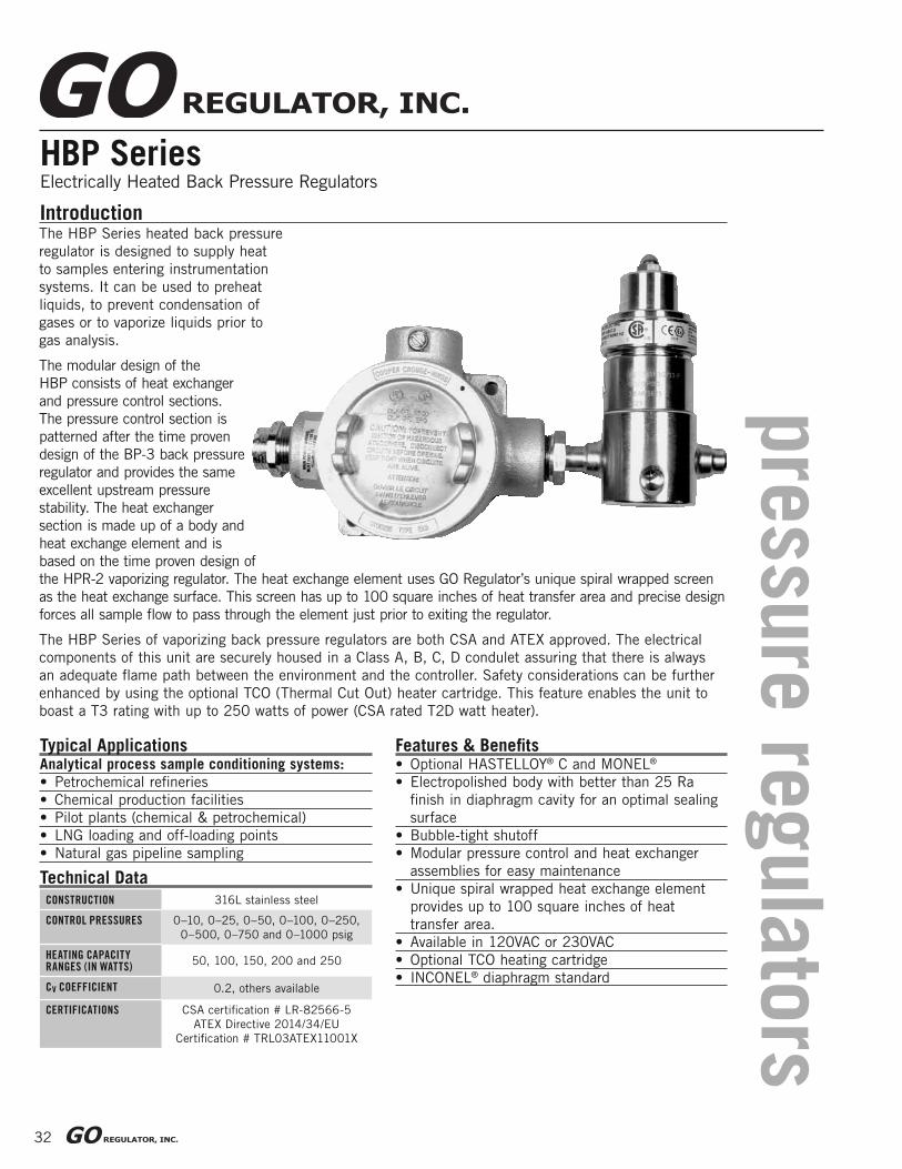
HBP SeriesElectrically Heated Back Pressure Regulators
Features & Benefi ts• Optional HASTELLOY® C and MONEL®
• Electropolished body with better than 25 Ra
fi nish in diaphragm cavity for an optimal sealing
surface
• Bubble-tight shutoff
• Modular pressure control and heat exchanger
assemblies for easy maintenance
• Unique spiral wrapped heat exchange element
provides up to 100 square inches of heat
transfer area.
• Available in 120VAC or 230VAC
• Optional TCO heating cartridge
• INCONEL® diaphragm standard
Introduction
Typical ApplicationsAnalytical process sample conditioning systems:
• Petrochemical refi neries
• Chemical production facilities
• Pilot plants (chemical & petrochemical)
• LNG loading and off-loading points
• Natural gas pipeline sampling
CONSTRUCTION 316L stainless steel
CONTROL PRESSURES 0–10, 0–25, 0–50, 0–100, 0–250,
0–500, 0–750 and 0–1000 psig
HEATING CAPACITY RANGES (IN WATTS)
50, 100, 150, 200 and 250
CV COEFFICIENT 0.2, others available
CERTIFICATIONS CSA certifi cation # LR-82566-5
ATEX Directive 2014/34/EU
Certifi cation # TRL03ATEX11001X
Technical Data
The HBP Series heated back pressure
regulator is designed to supply heat
to samples entering instrumentation
systems. It can be used to preheat
liquids, to prevent condensation of
gases or to vaporize liquids prior to
gas analysis.
The modular design of the
HBP consists of heat exchanger
and pressure control sections.
The pressure control section is
patterned after the time proven
design of the BP-3 back pressure
regulator and provides the same
excellent upstream pressure
stability. The heat exchanger
section is made up of a body and
heat exchange element and is
based on the time proven design of
the HPR-2 vaporizing regulator. The heat exchange element uses GO Regulator’s unique spiral wrapped screen
as the heat exchange surface. This screen has up to 100 square inches of heat transfer area and precise design
forces all sample fl ow to pass through the element just prior to exiting the regulator.
The HBP Series of vaporizing back pressure regulators are both CSA and ATEX approved. The electrical
components of this unit are securely housed in a Class A, B, C, D condulet assuring that there is always
an adequate fl ame path between the environment and the controller. Safety considerations can be further
enhanced by using the optional TCO (Thermal Cut Out) heater cartridge. This feature enables the unit to
boast a T3 rating with up to 250 watts of power (CSA rated T2D watt heater).
pre
ssure
regula
tors
33
HBP Series
How to Order
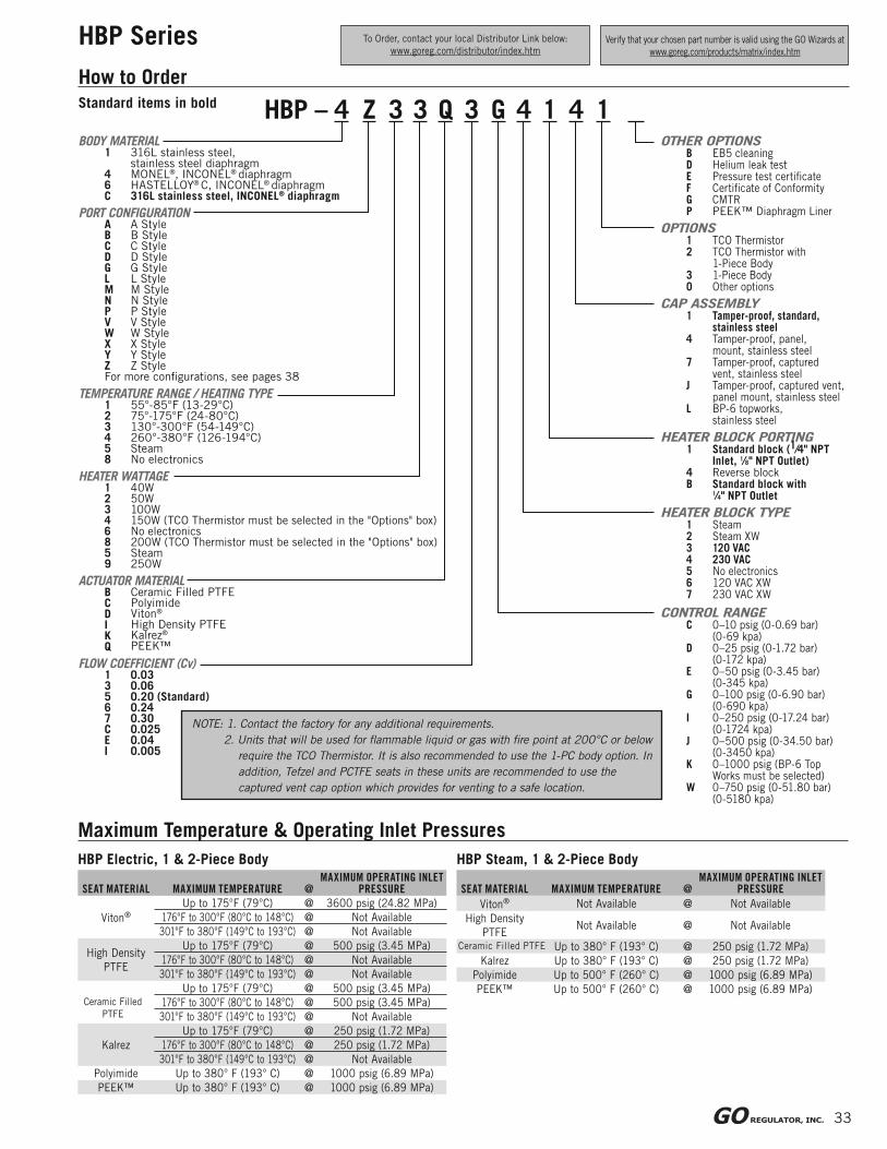
Maximum Temperature & Operating Inlet Pressures
HBP Electric, 1 & 2-Piece Body
SEAT MATERIAL MAXIMUM TEMPERATURE @MAXIMUM OPERATING INLET
PRESSURE
Viton®
Up to 175°F (79°C) @ 3600 psig (24.82 MPa)
176°F to 300°F (80°C to 148°C) @ Not Available
301°F to 380°F (149°C to 193°C) @ Not Available
High Density
PTFE
Up to 175°F (79°C) @ 500 psig (3.45 MPa)
176°F to 300°F (80°C to 148°C) @ Not Available
301°F to 380°F (149°C to 193°C) @ Not Available
Ceramic Filled
PTFE
Up to 175°F (79°C) @ 500 psig (3.45 MPa)
176°F to 300°F (80°C to 148°C) @ 500 psig (3.45 MPa)
301°F to 380°F (149°C to 193°C) @ Not Available
Kalrez
Up to 175°F (79°C) @ 250 psig (1.72 MPa)
176°F to 300°F (80°C to 148°C) @ 250 psig (1.72 MPa)
301°F to 380°F (149°C to 193°C) @ Not Available
Polyimide Up to 380° F (193° C) @ 1000 psig (6.89 MPa)
PEEK™ Up to 380° F (193° C) @ 1000 psig (6.89 MPa)
HBP Steam, 1 & 2-Piece Body
SEAT MATERIAL MAXIMUM TEMPERATURE @MAXIMUM OPERATING INLET
PRESSURE
Viton® Not Available @ Not Available
High Density
PTFENot Available @ Not Available
Ceramic Filled PTFE Up to 380° F (193° C) @ 250 psig (1.72 MPa)
Kalrez Up to 380° F (193° C) @ 250 psig (1.72 MPa)
Polyimide Up to 500° F (260° C) @ 1000 psig (6.89 MPa)
PEEK™ Up to 500° F (260° C) @ 1000 psig (6.89 MPa)
Standard items in bold
To Order, contact your local Distributor Link below:
www.goreg.com/distributor/index.htmVerify that your chosen part number is valid using the GO Wizards at
www.goreg.com/products/matrix/index.htm
HBP – 4 Z 3 3 Q 3 G 4 1 4 1BODY MATERIAL
1 316L stainless steel,stainless steel diaphragm
4 MONEL®, INCONEL® diaphragm6 HASTELLOY® C, INCONEL® diaphragmC 316L stainless steel, INCONEL® diaphragm
PORT CONFIGURATIONA A Style B B Style C C Style D D Style G G Style L L Style M M Style N N Style P P Style V V Style W W Style X X Style Y Y Style Z Z Style For more confi gurations, see pages 38
TEMPERATURE RANGE / HEATING TYPE1 55°-85°F (13-29°C)2 75°-175°F (24-80°C)3 130°-300°F (54-149°C)4 260°-380°F (126-194°C)5 Steam8 No electronics
HEATER WATTAGE1 40W2 50W3 100W4 150W (TCO Thermistor must be selected in the "Options" box)6 No electronics8 200W (TCO Thermistor must be selected in the "Options" box)5 Steam9 250W
ACTUATOR MATERIALB C D I K Q
Ceramic Filled PTFE PolyimideViton®
High Density PTFE Kalrez®
PEEK™
FLOW COEFFICIENT (Cv)1 0.033 0.065 0.20 (Standard)6 0.247 0.30C 0.025E 0.04I 0.005
OTHER OPTIONSB EB5 cleaningD Helium leak testE Pressure test certifi cateF Certifi cate of ConformityG CMTRP PEEK™ Diaphragm Liner
OPTIONS1 TCO Thermistor2 TCO Thermistor with
1-Piece Body3 1-Piece Body0 Other options
CAP ASSEMBLY1 Tamper-proof, standard,
stainless steel4 Tamper-proof, panel,
mount, stainless steel7 Tamper-proof, captured
vent, stainless steelJ Tamper-proof, captured vent,
panel mount, stainless steelL BP-6 topworks, stainless steel
HEATER BLOCK PORTING1 Standard block (1⁄4" NPT
Inlet, 1⁄8" NPT Outlet)4 Reverse blockB Standard block with
1⁄4" NPT Outlet
HEATER BLOCK TYPE1 Steam2 Steam XW3 120 VAC4 230 VAC5 No electronics6 120 VAC XW7 230 VAC XW
CONTROL RANGEC 0–10 psig (0-0.69 bar) (0-69 kpa)D 0–25 psig (0-1.72 bar) (0-172 kpa)E 0–50 psig (0-3.45 bar) (0-345 kpa)G 0–100 psig (0-6.90 bar) (0-690 kpa)I 0–250 psig (0-17.24 bar) (0-1724 kpa)J 0–500 psig (0-34.50 bar) (0-3450 kpa)K 0–1000 psig (BP-6 Top
Works must be selected)W 0–750 psig (0-51.80 bar) (0-5180 kpa)
NOTE: 1. Contact the factory for any additional requirements.
2. Units that will be used for fl ammable liquid or gas with fi re point at 200°C or below
require the TCO Thermistor. It is also recommended to use the 1-PC body option. In
addition, Tefzel and PCTFE seats in these units are recommended to use the
captured vent cap option which provides for venting to a safe location.

34
HBP Series
Outline & Mounting Dimensions
MAIN
POW
ER W
IRIN
GM
UST H
AVE 85°C (185°F)
MIN
IMU
M R
ATIN
G
.50 [12.7mm]
Ø 2.0 [51mm]
Ø 2.25 [57mm]
1/4 NPT Sample Inlet
Panel mount option requires 1.390" (35.3mm) minimum diameter panel cut out
Weight 8.7 lbs (3.95 kg)
5.68 [144mm]
1/8 NPT Outlet
6.57 [167mm]
Standard vent to atmosphere
10-32 X .25 Min full thds (2X)
10.5 [267mm]
4.68 [119mm]
1- 55°F / 13°C 5- 75°F / 24°C2- 60°F / 16°C 6- 80°F / 27°C3- 65°F / 18°C 7- 85°F / 29°C4- 70°F / 21°C
43 5 Range
A1
2 6
7
GO Regulator Part#115791Spartanburg, SC 29303(864)574-7966°C/°F
Ø .30 [7.6mm] on 3.09 [78.6mm] BC
1.50 [38mm]
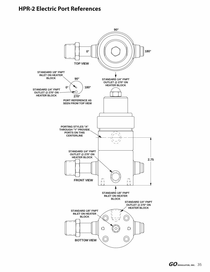
35
STANDARD 1/8" FNPT INLET ON HEATER
BLOCK
STANDARD 1/4" FNPT OUTLET @ 270° ON
HEATER BLOCK
2.75
STANDARD 1/4" FNPT OUTLET @ 270° ON
HEATER BLOCK
STANDARD 1/8" FNPT INLET ON HEATER
BLOCK
STANDARD 1/8" FNPT INLET ON HEATER
BLOCK
BOTTOM VIEW
STANDARD 1/4" FNPT OUTLET @ 270° ON
HEATER BLOCK
FRONT VIEW
STANDARD 1/4" FNPT OUTLET @ 270° ON
HEATER BLOCK
PORT REFERENCE AS SEEN FROM TOP VIEW
270°
0° 180°
PORTING STYLES "A" THROUGH "Y" PROVIDE
PORTS ON THIS CENTERLINE
90°
TOP VIEW
90°
0° 180°
HPR-2 Electric Port References
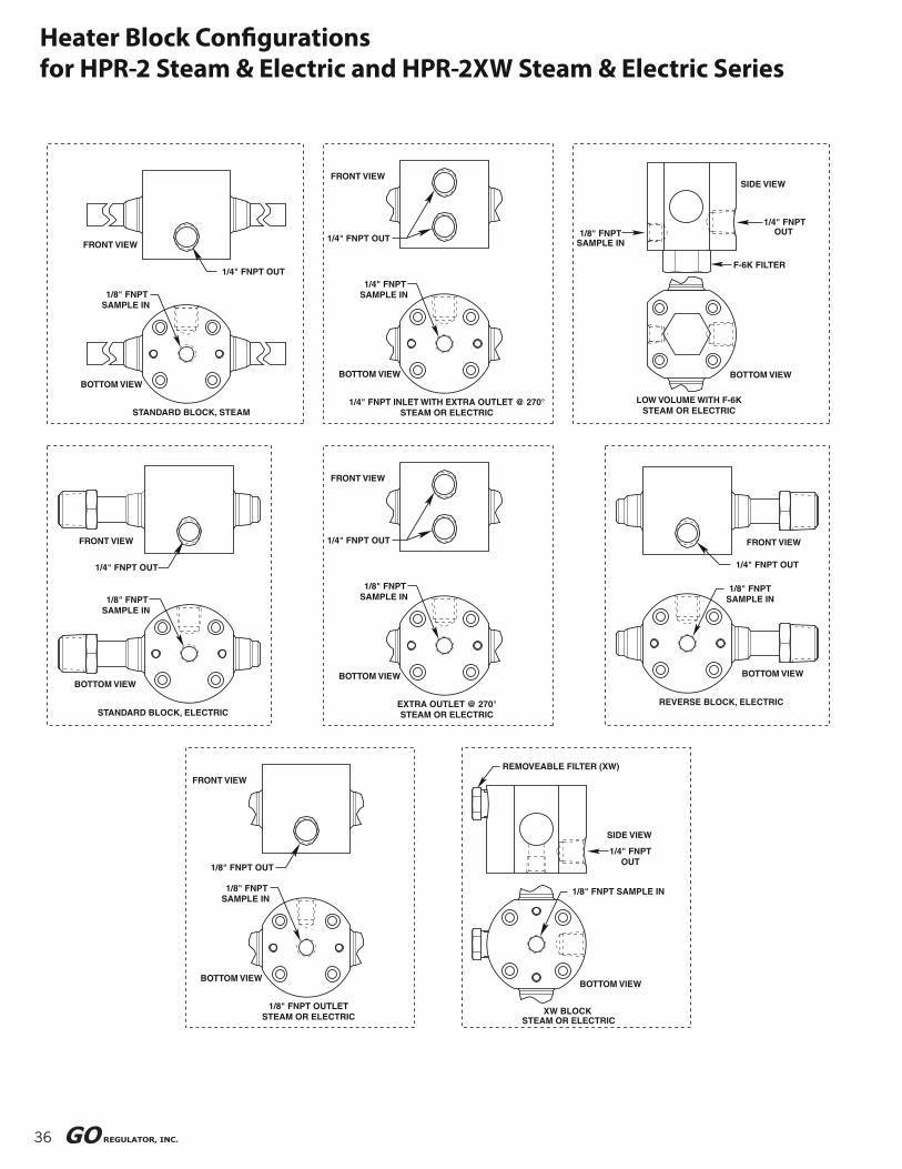
36
Heater Block Confi gurationsfor HPR-2 Steam & Electric and HPR-2XW Steam & Electric Series
BOTTOM VIEW
1/8" FNPTSAMPLE IN
FRONT VIEW
1/8" FNPT OUTLETSTEAM OR ELECTRIC
1/8" FNPT OUT
SIDE VIEW
1/4" FNPTOUT
BOTTOM VIEW
REMOVEABLE FILTER (XW)
XW BLOCKSTEAM OR ELECTRIC
1/8" FNPT SAMPLE IN
1/4" FNPT OUT
F-6K FILTER
1/8" FNPT SAMPLE IN
SIDE VIEW
BOTTOM VIEW
LOW VOLUME WITH F-6KSTEAM OR ELECTRIC
BOTTOM VIEW
1/8" FNPTSAMPLE IN
FRONT VIEW
STANDARD BLOCK, STEAM
1/4" FNPT OUT
BOTTOM VIEW
1/4" FNPTSAMPLE IN
FRONT VIEW
1/4" FNPT INLET WITH EXTRA OUTLET @ 270°STEAM OR ELECTRIC
1/4" FNPT OUT
STANDARD BLOCK, ELECTRIC
BOTTOM VIEW
FRONT VIEW
1/8" FNPTSAMPLE IN
1/4" FNPT OUT
FRONT VIEW
BOTTOM VIEW
REVERSE BLOCK, ELECTRIC
1/8" FNPTSAMPLE IN
1/4" FNPT OUT
BOTTOM VIEW
1/8" FNPTSAMPLE IN
FRONT VIEW
EXTRA OUTLET @ 270°STEAM OR ELECTRIC
1/4" FNPT OUT

37
1/4" FNPT OUT1/8" FNPT
SAMPLE IN
SIDE VIEW
BOTTOM VIEW
LOW VOLUME WITHOUT F-6KSTEAM OR ELECTRIC
1/4" FNPT OUT
F-6K FILTER
1/8" FNPT SAMPLE IN
SIDE VIEW
BOTTOM VIEW
LOW VOLUME EXTRA OUTLET WITH F-6KSTEAM OR ELECTRIC
1/4" FNPT OUT
F-6K FILTER
1/8" FNPT SAMPLE IN
SIDE VIEW
REMOVABLE FILTER (XW)
BOTTOM VIEW
LOW VOLUME XW WITH F-6KSTEAM OR ELECTRIC
BOTTOM VIEW
F-6K FILTER
FRONT VIEW
LOW VOLUME REVERSE BLOCK WITH F-6K, ELECTRIC
1/8" FNPT SAMPLE IN
1/4" FNPT OUT
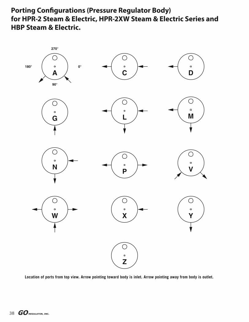
38
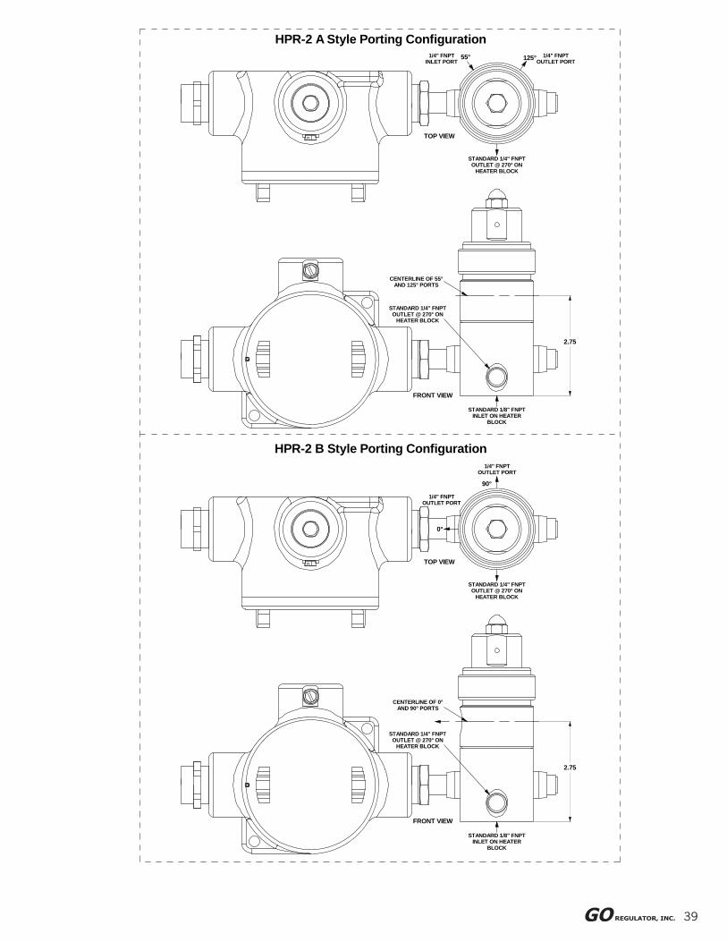
Porting Confi gurations (Pressure Regulator Body)for HPR-2 Steam & Electric, HPR-2XW Steam & Electric Series andHBP Steam & Electric.
Location of ports from top view. Arrow pointing toward body is inlet. Arrow pointing away from body is outlet.
A0°
90°
180°
270°
C D
G L M
NP V
W X
Z
Y
39
HPR-2 B Style Porting Configuration
STANDARD 1/8" FNPT INLET ON HEATER
BLOCK
FRONT VIEW
STANDARD 1/4" FNPT OUTLET @ 270° ON
HEATER BLOCK
CENTERLINE OF 0° AND 90° PORTS
2.75
STANDARD 1/4" FNPT OUTLET @ 270° ON
HEATER BLOCK
1/4" FNPT OUTLET PORT
TOP VIEW
1/4" FNPT OUTLET PORT
0°
90°
HPR-2 A Style Porting Configuration
STANDARD 1/8" FNPT INLET ON HEATER
BLOCK
FRONT VIEW
CENTERLINE OF 55° AND 125° PORTS
STANDARD 1/4" FNPT OUTLET @ 270° ON
HEATER BLOCK
2.75
STANDARD 1/4" FNPT OUTLET @ 270° ON
HEATER BLOCK
TOP VIEW
1/4" FNPT INLET PORT
55° 125° 1/4" FNPT OUTLET PORT

40
HPR-2 C Style Porting Configuration
2.75
STANDARD 1/4" FNPT OUTLET @ 270° ON
HEATER BLOCK
FRONT VIEW
STANDARD 1/8" FNPT INLET ON HEATER
BLOCK
CENTERLINE OF 180° PORT
TOP VIEW
STANDARD 1/4" FNPT OUTLET @ 270° ON
HEATER BLOCK
180°1/4" FNPT
OUTLET PORT
HPR-2 D Style Porting Configuration
CENTERLINE OF 0° AND 180° PORTS
FRONT VIEW
STANDARD 1/4" FNPT OUTLET @ 270° ON
HEATER BLOCK
2.75
STANDARD 1/8" FNPT INLET ON HEATER
BLOCK
1/4" FNPT INLET PORT
TOP VIEW
0°
STANDARD 1/4" FNPT OUTLET @ 270° ON
HEATER BLOCK
1/4" FNPT OUTLET PORT
180°

41
HPR-2 G Style Porting Configuration
HPR-2 L Style Porting Configuration
STANDARD 1/8" FNPT INLET ON HEATER
BLOCK
FRONT VIEW
CENTERLINE OF 0°, 90° AND 180° PORTS
STANDARD 1/4" FNPT OUTLET @ 270° ON
HEATER BLOCK
2.75
STANDARD 1/4" FNPT OUTLET @ 270° ON
HEATER BLOCK
1/4" FNPT OUTLET PORT
TOP VIEW
1/4" FNPT INLET PORT
0°
90°
1/4" FNPT OUTLET PORT
180°
STANDARD 1/8" FNPT INLET ON HEATER
BLOCK
FRONT VIEW
STANDARD 1/4" FNPT OUTLET @ 270° ON
HEATER BLOCK
CENTERLINE OF 90° PORT
2.75
1/4" FNPT INLET PORT
STANDARD 1/4" FNPT OUTLET @ 270° ON
HEATER BLOCK
TOP VIEW
90°
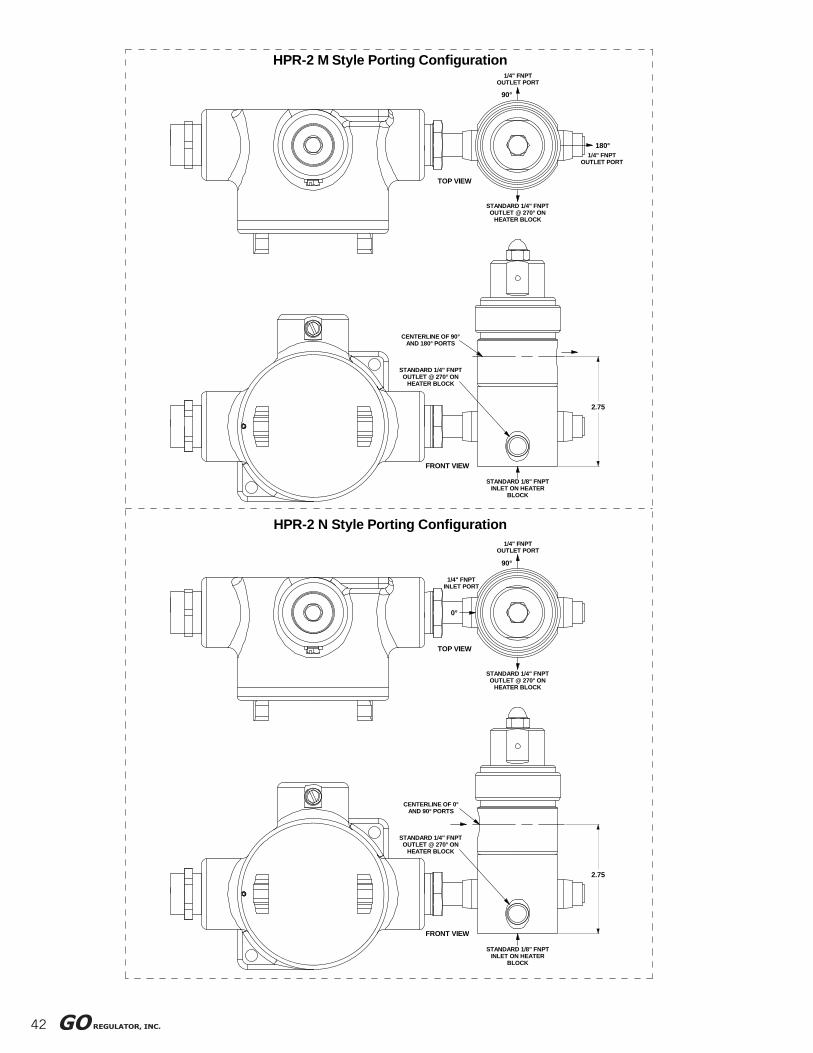
42
HPR-2 N Style Porting Configuration
STANDARD 1/8" FNPT INLET ON HEATER
BLOCK
FRONT VIEW
CENTERLINE OF 0° AND 90° PORTS
STANDARD 1/4" FNPT OUTLET @ 270° ON
HEATER BLOCK
2.75
STANDARD 1/4" FNPT OUTLET @ 270° ON
HEATER BLOCK
1/4" FNPT OUTLET PORT
TOP VIEW
0°
1/4" FNPT INLET PORT
90°
HPR-2 M Style Porting Configuration
STANDARD 1/8" FNPT INLET ON HEATER
BLOCK
FRONT VIEW
STANDARD 1/4" FNPT OUTLET @ 270° ON
HEATER BLOCK
CENTERLINE OF 90° AND 180° PORTS
2.75
STANDARD 1/4" FNPT OUTLET @ 270° ON
HEATER BLOCK
1/4" FNPT OUTLET PORT
TOP VIEW
90°
1/4" FNPT OUTLET PORT
180°

43
STANDARD 1/4" FNPT OUTLET @ 270° ON
HEATER BLOCK
CENTERLINE OF 55° AND 125° PORTS
HPR-2 V Style Porting Configuration
STANDARD 1/8" FNPT INLET ON HEATER
BLOCK
FRONT VIEW
2.75
STANDARD 1/4" FNPT OUTLET @ 270° ON
HEATER BLOCK
TOP VIEW
1/4" FNPT OUTLET PORT
55° 125° 1/4" FNPT INLET PORT
HPR-2 P Style Porting Configuration
STANDARD 1/4" FNPT OUTLET @ 270° ON
HEATER BLOCK
CENTERLINE OF 0° AND 180° PORTS
STANDARD 1/8" FNPT INLET ON HEATER
BLOCK
FRONT VIEW
2.75
STANDARD 1/4" FNPT OUTLET @ 270° ON
HEATER BLOCK
TOP VIEW
1/4" FNPT OUTLET PORT
0°1/4" FNPT
OUTLET PORT
180°
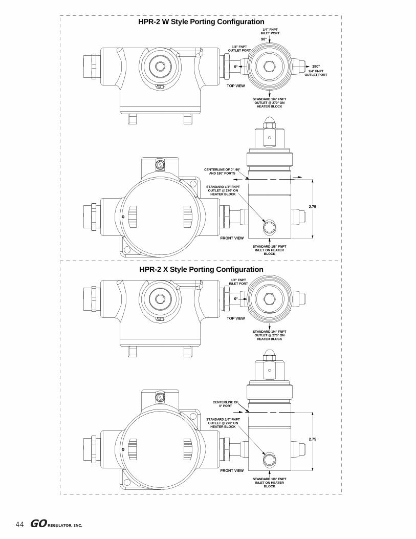
44
HPR-2 W Style Porting Configuration
HPR-2 X Style Porting Configuration
STANDARD 1/8" FNPT INLET ON HEATER
BLOCK
FRONT VIEW
CENTERLINE OF 0° PORT
STANDARD 1/4" FNPT OUTLET @ 270° ON
HEATER BLOCK
2.75
STANDARD 1/4" FNPT OUTLET @ 270° ON
HEATER BLOCK
1/4" FNPT INLET PORT
0°
TOP VIEW
STANDARD 1/8" FNPT INLET ON HEATER
BLOCK
FRONT VIEW
CENTERLINE OF 0°, 90° AND 180° PORTS
STANDARD 1/4" FNPT OUTLET @ 270° ON
HEATER BLOCK
2.75
1/4" FNPT INLET PORT
STANDARD 1/4" FNPT OUTLET @ 270° ON
HEATER BLOCK
TOP VIEW
1/4" FNPT OUTLET PORT
0°
90°
1/4" FNPT OUTLET PORT
180°
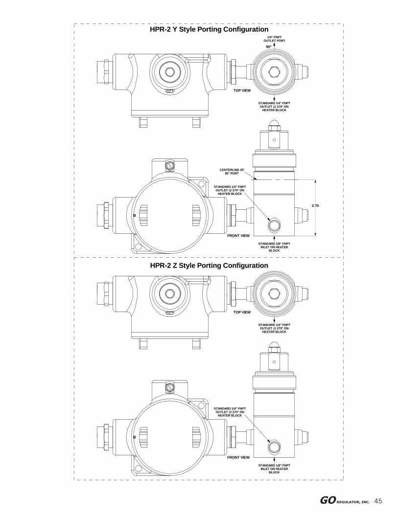
45
STANDARD 1/8" FNPT INLET ON HEATER
BLOCK
HPR-2 Z Style Porting Configuration
STANDARD 1/8" FNPT INLET ON HEATER
BLOCK
FRONT VIEW
STANDARD 1/4" FNPT OUTLET @ 270° ON
HEATER BLOCK
STANDARD 1/4" FNPT OUTLET @ 270° ON
HEATER BLOCK
TOP VIEW
HPR-2 Y Style Porting Configuration
STANDARD 1/4" FNPT OUTLET @ 270° ON
HEATER BLOCK
FRONT VIEW
CENTERLINE OF 90° PORT
2.75
STANDARD 1/4" FNPT OUTLET @ 270° ON
HEATER BLOCK
1/4" FNPT OUTLET PORT
90°
TOP VIEW
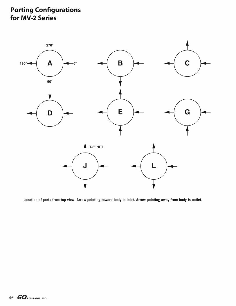
46
Porting Confi gurationsfor MV-2 Series
Location of ports from top view. Arrow pointing toward body is inlet. Arrow pointing away from body is outlet.
A 0°
90°
180°
270°
B C
D E G
J
1/8" NPT
L

47
90°
180° 0°
270°
REFERENCE CLOCK
LOCATION OF PORTS FROM TOP OF SECOND STAGE
Arrow pointing toward body is inlet. Arrow pointing away from body is outlet.
90° ports are standard inlet and outlet ports, see graphic view.
VUL
GED
A B C
CV2 Porting Confi gurations
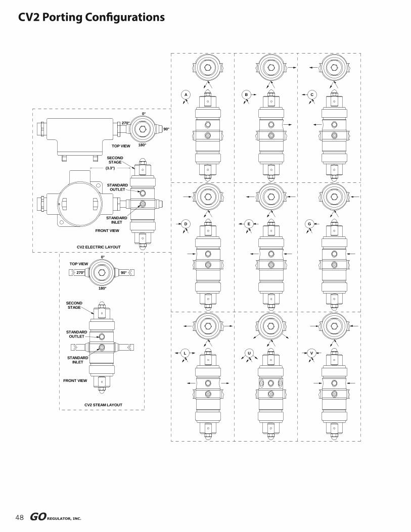
48
CV2 ELECTRIC LAYOUT
CV2 STEAM LAYOUT
STANDARDINLET
FRONT VIEW
L
STANDARDOUTLET
SECONDSTAGE
TOP VIEW
270°
180°
0°
90°
U V
FRONT VIEW
STANDARDINLET
STANDARDOUTLET
SECONDSTAGE
(3.3")
D
TOP VIEW 180°
270°
0°
90°
A
E G
B C
CV2 Porting Confi gurations

49
Arrow pointing toward body is inlet. Arrow pointing away from body is outlet.
condulet cap
Location of ports viewing from top of Regulator "A"
Electrically Heated Ref. Clock
REG. A
Arrow pointing toward body is inlet. Arrow pointing away from body is
outlet.
*Not recommended for use with gauge on electrically heated units due
to condulet location.
"A" style porting has one inlet and one outlet port. All other porting styles provide additional ports
located as shown.
REG. A
F*
REG. A
E*
REG. A
D*
C*
B
REG. A
ASTANDARD
REG. A
REG. B
REG. A
N*
REG. A
NOSCREEN
NOSCREEN
NOSCREEN
NOSCREEN
NOSCREEN
NOSCREEN
REG. A
REG. B
NOSCREENV*
NOSCREEN
NOSCREEN
NOSCREEN
NOSCREEN
NOSCREEN
NOSCREEN
VAPORIZINGSCREEN
REG. A
Q*REG. B
NOSCREEN
REG. B
REG. A
H*
REG. B
I*
REG. A
REG. B
M
REG. A
270°
REG. B
NOSCREEN
REG. B
REG. B
NOSCREEN
REG. B
NOSCREEN
REG. B
REG. B REG. B
#1
#2180°180°
VAPORIZINGSCREEN
REG. A REG. A
Location of ports viewing from top of Regulator "A"
0°
90°
heat exchange
tube0°
270° 90°
Steam Heated Ref. Clock
REG. B
REG. B
REG. B INLET
REG. ATO SCREEN
REG. B
L*
REG. B
REG. A
K*
REG. ATO SCREEN
REG. A INLET
REG. B
#4*
REG. B
G
REG. A
U*
Porting Confi gurationsfor DH2 Steam & Electric Series
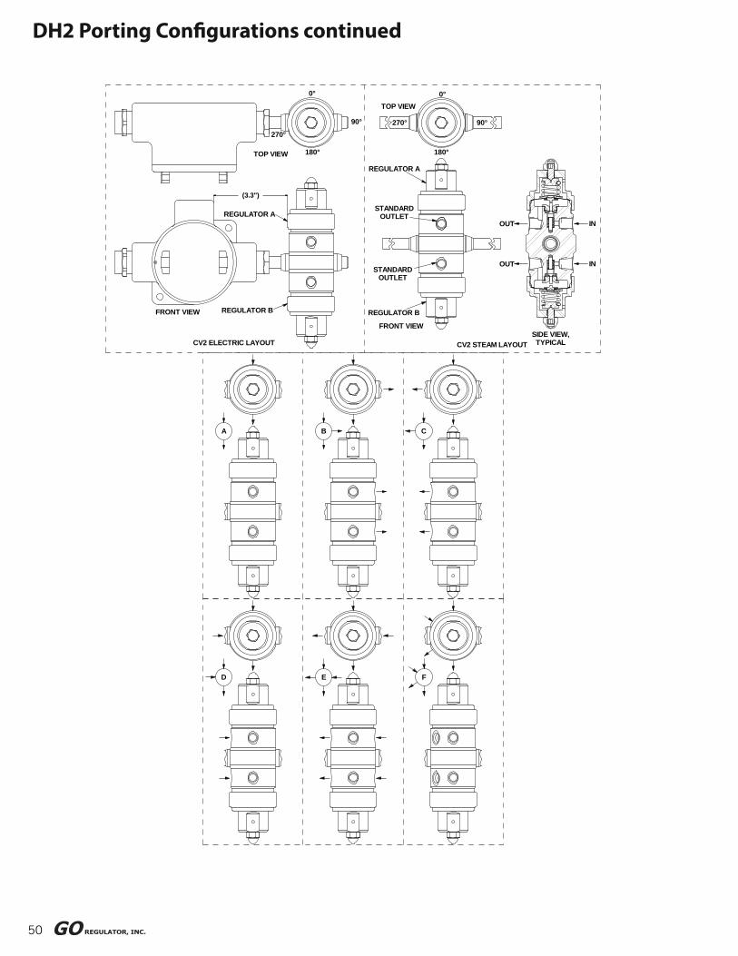
50
D E F
FRONT VIEW
STANDARDOUTLET
STANDARDOUTLET
REGULATOR A
REGULATOR B
CV2 ELECTRIC LAYOUT
REGULATOR B
A
FRONT VIEW
B
REGULATOR A
(3.3")
0°
180°TOP VIEW
270°
90°
CV2 STEAM LAYOUT
C
SIDE VIEW, TYPICAL
OUT
OUT
180°
0°TOP VIEW
270° 90°
IN
IN
DH2 Porting Confi gurations continued
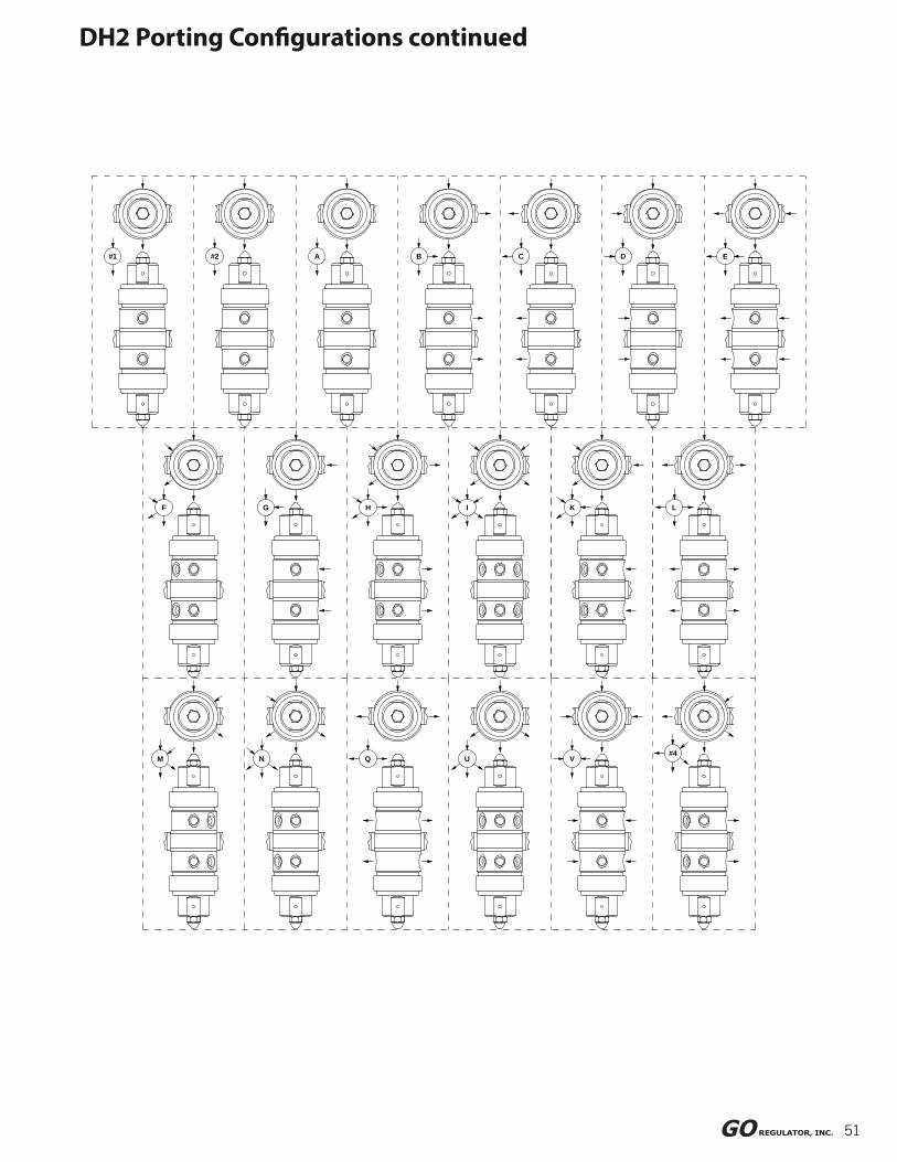
51
DH2 Porting Confi gurations continued
#1
LK
Q UM N#4
V
F G H I
A#2 B C D E

52
Hastelloy® is a registered trademark of Haynes International, Inc.Monel® is a registered trademark of Special Metals Corporation.Tefzel® are registered trademarks of the DuPont Company.Kel-F® is a registered trademark of 3M Company.PEEK™ is a trademark of Victrex PLC.Viton® is a registered trademark of DuPont Dow Elastomers.

Proudly Distributed By:
We specialize in small bore instrumentation products up to 2” that deliver benchmark
performance quality & safety; provide the broadest array of superior alloy off erings in
the market; decades of proven success in a wide range of industries; a roster of “who’s
who” customers & projects globally; original “Best Solution” engineering & designs; and
are focused on continuous improvement in all aspects of our business.
The Small Bore Instrumentation Specialists
CRANE INSTRUMENTATION &SAMPLING Inc.405 Centura Ct.Spartanburg, SC 29305, USA
Tel: 1-864-574-7966PO Box 4866, Spartanburg, SC29305-4866 USA
Crane Co., and its subsidiaries cannot accept responsibility for possible errors in catalogues, brochures, other printed materials, and
website information. Crane Co. reserves the right to alter its products without notice, including products already on order provided
that such alteration can be made without changes being necessary in specifi cations already agreed. All trademarks in this material
are the property of the Crane Co. or its subsidiaries. The Crane and Crane brands logotype (CENTER LINE®, COMPAC-NOZ®, CRANE®,
DEPA® & ELRO®, DOPAK®, DUO-CHEK®, FLOWSEAL®, GYROLOK®, GO REGULATOR®, HOKE®, JENKINS®, KROMBACH®, NOZ-CHEK®,
PACIFIC VALVES®, RESISTOFLEX®, REVO®, SAUNDERS®, STOCKHAM®, TEXAS SAMPLING®, TRIANGLE®, UNI-CHEK®, VALVES®, WTA®, and
XOMOX® ) are registered trademarks of Crane Co. All rights reserved.
GVPR • 03/20/20 • APS653