Embed Size (px)
Citation preview
Power Systems Engineering Center
Prevention of Unintentional Islands in Power Systems with Distributed Resources
Ben Kroposki National Renewable Energy Laboratory
Webinar - August 24, 2016 NREL/PR-5D00-67185
A seminar with audio is posted at NREL’s YouTube channel: https://www.youtube.com/watch?v=-xjprcbFK3Q
2
Presentation Outline
• Types of islands in power systems with DR
• Issues with unintentional islands
• Methods of protecting against unintentional islands
• Standard testing for unintentional islanding
• Advanced testing of inverters for anti-islanding functionality
• Probability of unintentional islanding
• The future of anti-islanding protection
• References
3
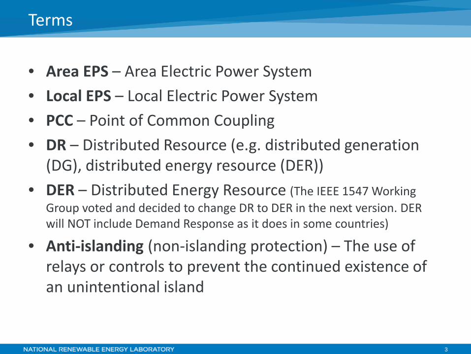
• Area EPS – Area Electric Power System • Local EPS – Local Electric Power System • PCC – Point of Common Coupling • DR – Distributed Resource (e.g. distributed generation
(DG), distributed energy resource (DER)) • DER – Distributed Energy Resource (The IEEE 1547 Working
Group voted and decided to change DR to DER in the next version. DER will NOT include Demand Response as it does in some countries)
• Anti-islanding (non-islanding protection) – The use of relays or controls to prevent the continued existence of an unintentional island
Terms
4
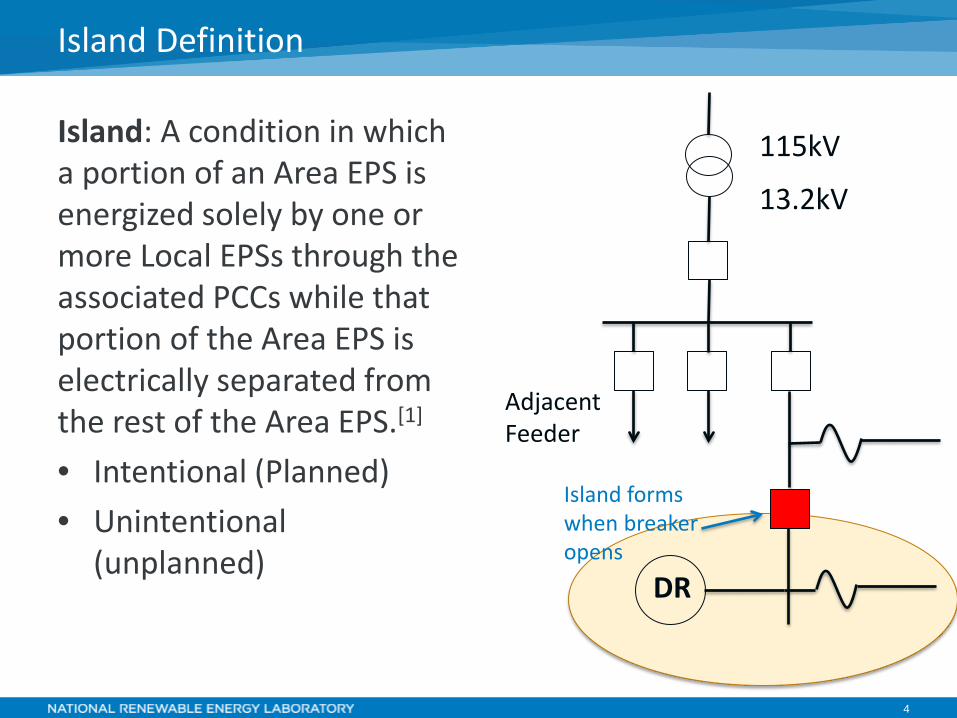
Island: A condition in which a portion of an Area EPS is energized solely by one or more Local EPSs through the associated PCCs while that portion of the Area EPS is electrically separated from the rest of the Area EPS.[1]
• Intentional (Planned) • Unintentional
(unplanned)
Island Definition
DR
115kV
13.2kV
Adjacent Feeder
Island forms when breaker opens
5
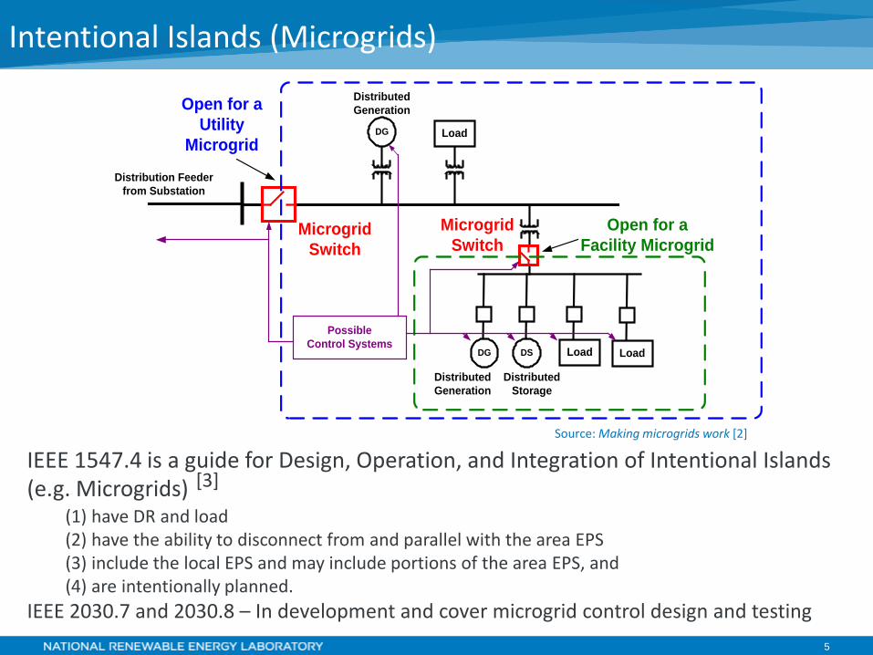
Intentional Islands (Microgrids)
IEEE 1547.4 is a guide for Design, Operation, and Integration of Intentional Islands (e.g. Microgrids) [3]
(1) have DR and load (2) have the ability to disconnect from and parallel with the area EPS (3) include the local EPS and may include portions of the area EPS, and (4) are intentionally planned.
IEEE 2030.7 and 2030.8 – In development and cover microgrid control design and testing
Distribution Feeder from Substation
Open for a Utility
Microgrid
DSDG Load Load
DG Load
MicrogridSwitch
Distributed Generation
Distributed Generation
Distributed Storage
Open for a Facility Microgrid
PossibleControl Systems
MicrogridSwitch
Source: Making microgrids work [2]
6
• Personnel Safety – Unintentional islands can cause hazards for utility workers if they assume downed lines are not energized during restoration
• Overvoltages – Transient overvoltages due to rapid loss of load are possible. If an adequate ground source is not present in the island, a ground fault can result in voltages that exceed 173% on the unfaulted phases.
• Reconnection out of phase - This can result in large transient torques applied to motors connected to the islanded area EPS and their mechanical systems (e.g., shafts, blowers, and pumps), which could result in damage or failure.
• Power Quality – Unplanned island area EPS may not have suitable power quality for loads
• Protection – Unintentional islands may not provide sufficient fault current to operate fuses or overcurrent relay protection devices inside island
Issues with Unintentional Islanding
References [4]-[7]
7
• Synchronous generators are voltage source devices that can support islanded grid operations. Synchronous generators are typical in diesel or natural gas powered engine-generators.
• Induction generators usually will not be able to support an island but will instead cease to produce current because of the loss of reactive power, which is necessary to support a rotating magnetic field within the generator. If sufficient capacitive reactance is available to supply the reactive power requirements of the induction generator field, either through the installation of power factor correction capacitors or the presence of considerable cable-type power conductors, it may be necessary to provide for direct detection of faults in a manner similar to that of synchronous generators.[4] Induction generators are found in some engine-gen sets and wind turbines.
• Inverter-Based DR are typically current-source devices that require a voltage-source (typically the utility grid) to synchronize to. Voltage-source (e.g. grid forming) inverters do have the ability to support islanded operation. Inverters are found in PV systems, wind turbines, microturbines, fuel cells, and battery energy storage.
Understanding DR Sources
References [4]
8
IEEE 1547: Unintentional Islanding Requirement
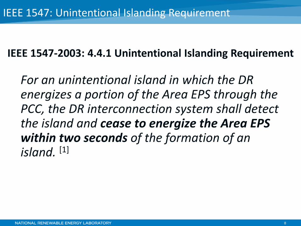
For an unintentional island in which the DR energizes a portion of the Area EPS through the PCC, the DR interconnection system shall detect the island and cease to energize the Area EPS within two seconds of the formation of an island. [1]
IEEE 1547-2003: 4.4.1 Unintentional Islanding Requirement
9
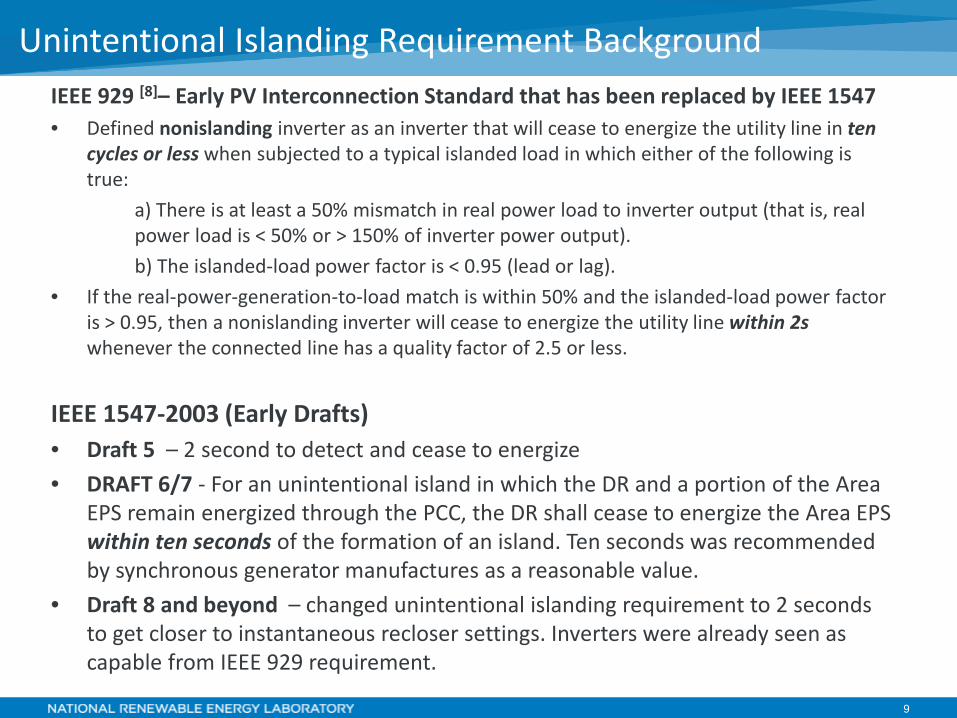
IEEE 929 [8]– Early PV Interconnection Standard that has been replaced by IEEE 1547 • Defined nonislanding inverter as an inverter that will cease to energize the utility line in ten
cycles or less when subjected to a typical islanded load in which either of the following is true:
a) There is at least a 50% mismatch in real power load to inverter output (that is, real power load is < 50% or > 150% of inverter power output). b) The islanded-load power factor is < 0.95 (lead or lag).
• If the real-power-generation-to-load match is within 50% and the islanded-load power factor is > 0.95, then a nonislanding inverter will cease to energize the utility line within 2s whenever the connected line has a quality factor of 2.5 or less.
IEEE 1547-2003 (Early Drafts) • Draft 5 – 2 second to detect and cease to energize • DRAFT 6/7 - For an unintentional island in which the DR and a portion of the Area
EPS remain energized through the PCC, the DR shall cease to energize the Area EPS within ten seconds of the formation of an island. Ten seconds was recommended by synchronous generator manufactures as a reasonable value.
• Draft 8 and beyond – changed unintentional islanding requirement to 2 seconds to get closer to instantaneous recloser settings. Inverters were already seen as capable from IEEE 929 requirement.
Unintentional Islanding Requirement Background
10
IEEE 1547-2003: Unintentional Islanding Requirement
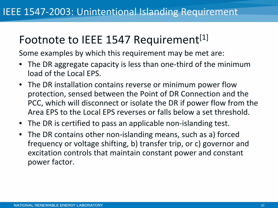
Footnote to IEEE 1547 Requirement[1]
Some examples by which this requirement may be met are: • The DR aggregate capacity is less than one-third of the minimum
load of the Local EPS. • The DR installation contains reverse or minimum power flow
protection, sensed between the Point of DR Connection and the PCC, which will disconnect or isolate the DR if power flow from the Area EPS to the Local EPS reverses or falls below a set threshold.
• The DR is certified to pass an applicable non-islanding test. • The DR contains other non-islanding means, such as a) forced
frequency or voltage shifting, b) transfer trip, or c) governor and excitation controls that maintain constant power and constant power factor.
11
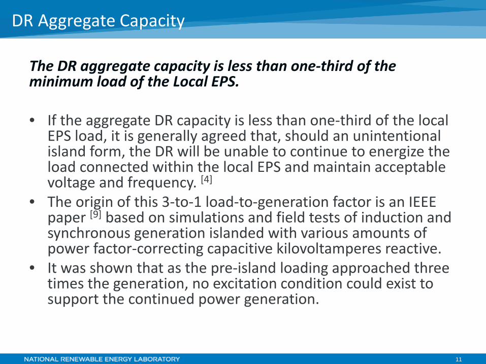
The DR aggregate capacity is less than one-third of the minimum load of the Local EPS.
• If the aggregate DR capacity is less than one-third of the local
EPS load, it is generally agreed that, should an unintentional island form, the DR will be unable to continue to energize the load connected within the local EPS and maintain acceptable voltage and frequency. [4]
• The origin of this 3-to-1 load-to-generation factor is an IEEE paper [9] based on simulations and field tests of induction and synchronous generation islanded with various amounts of power factor-correcting capacitive kilovoltamperes reactive.
• It was shown that as the pre-island loading approached three times the generation, no excitation condition could exist to support the continued power generation.
DR Aggregate Capacity
12
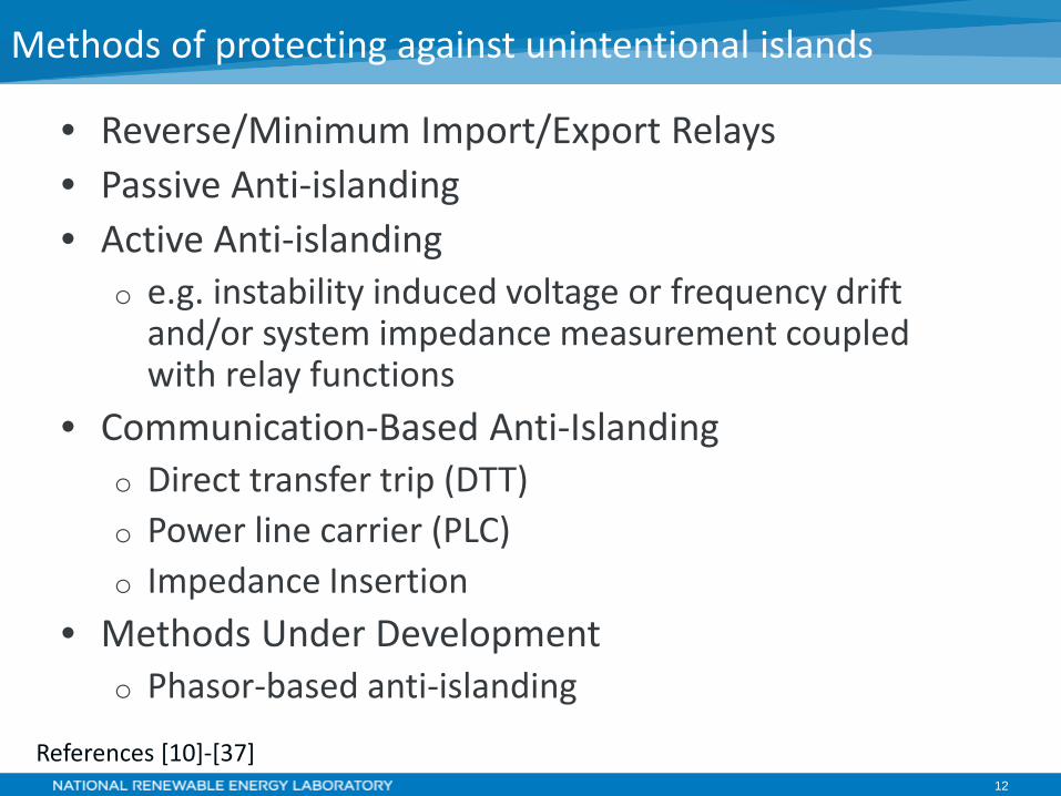
Methods of protecting against unintentional islands
• Reverse/Minimum Import/Export Relays • Passive Anti-islanding • Active Anti-islanding
o e.g. instability induced voltage or frequency drift and/or system impedance measurement coupled with relay functions
• Communication-Based Anti-Islanding o Direct transfer trip (DTT) o Power line carrier (PLC) o Impedance Insertion
• Methods Under Development o Phasor-based anti-islanding
References [10]-[37]
13
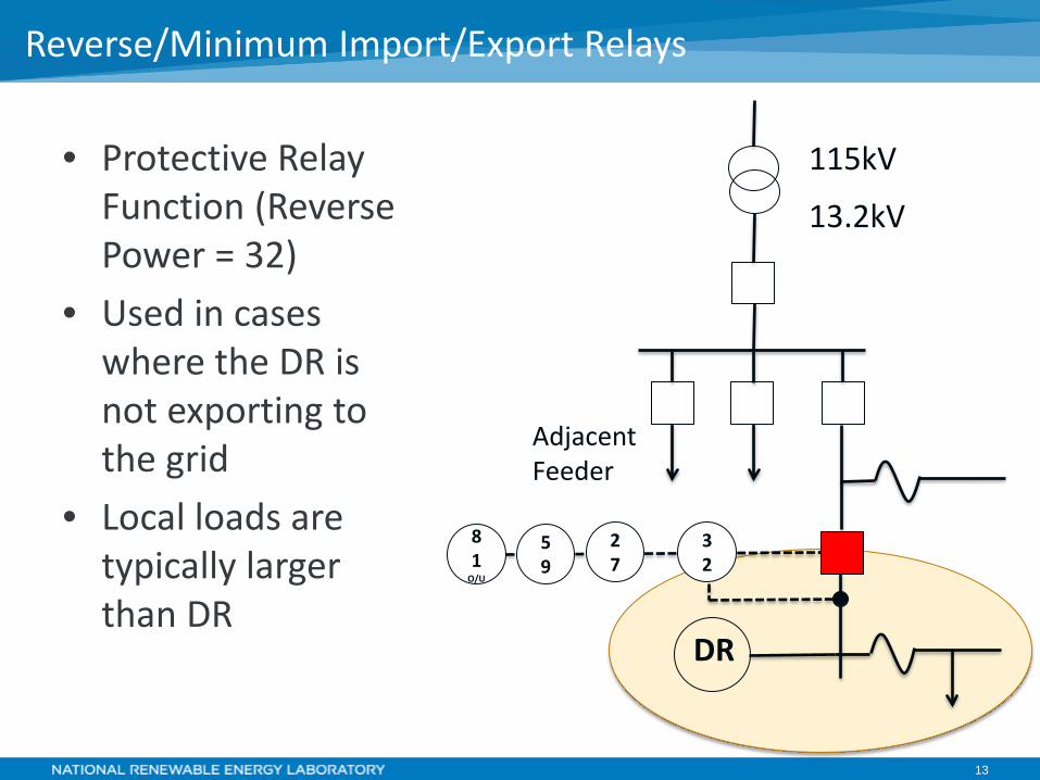
• Protective Relay Function (Reverse Power = 32)
• Used in cases where the DR is not exporting to the grid
• Local loads are typically larger than DR
Reverse/Minimum Import/Export Relays
DR
115kV
13.2kV
Adjacent Feeder
81
O/U
59
27
32
14
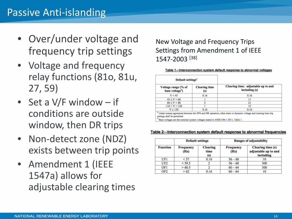
• Over/under voltage and frequency trip settings
• Voltage and frequency relay functions (81o, 81u, 27, 59)
• Set a V/F window – if conditions are outside window, then DR trips
• Non-detect zone (NDZ) exists between trip points
• Amendment 1 (IEEE 1547a) allows for adjustable clearing times
Passive Anti-islanding
New Voltage and Frequency Trips Settings from Amendment 1 of IEEE 1547-2003 [38]
15
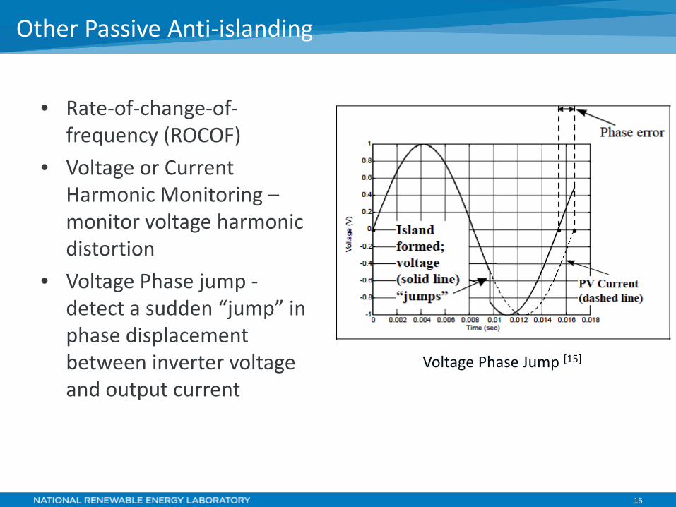
• Rate-of-change-of-frequency (ROCOF)
• Voltage or Current Harmonic Monitoring – monitor voltage harmonic distortion
• Voltage Phase jump - detect a sudden “jump” in phase displacement between inverter voltage and output current
Other Passive Anti-islanding
Voltage Phase Jump [15]
16
• Impedance Measurement • Detection of Impedance at
a Specific Frequency • Slip-mode Frequency Shift • Frequency Bias • Sandia Frequency Shift • Sandia Voltage Shift • Frequency Jump • ENS or MSD (a device using
multiple methods)
Active Anti-islanding
Active methods generally attempt to detect a loss in grid by actively trying to changing the voltage and/or frequency of the grid, and then detecting whether or not the grid changed.
17
• Power Line Carrier – Provide a permissive run signal, when signal goes away, the DR ceases to energize circuit
• Impedance Insertion – Remotely add capacitors that cause a large enough voltage change to trip O/U voltage protection
• DTT – next slide
Communications-based Methods
18
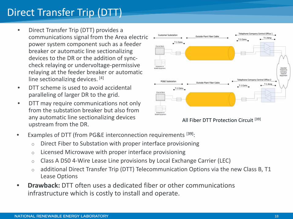
• Direct Transfer Trip (DTT) provides a communications signal from the Area electric power system component such as a feeder breaker or automatic line sectionalizing devices to the DR or the addition of sync-check relaying or undervoltage-permissive relaying at the feeder breaker or automatic line sectionalizing devices. [4]
• DTT scheme is used to avoid accidental paralleling of larger DR to the grid.
• DTT may require communications not only from the substation breaker but also from any automatic line sectionalizing devices upstream from the DR.
Direct Transfer Trip (DTT)
• Examples of DTT (from PG&E interconnection requirements [39]: o Direct Fiber to Substation with proper interface provisioning o Licensed Microwave with proper interface provisioning o Class A DS0 4-Wire Lease Line provisions by Local Exchange Carrier (LEC) o additional Direct Transfer Trip (DTT) Telecommunication Options via the new Class B, T1
Lease Options • Drawback: DTT often uses a dedicated fiber or other communications
infrastructure which is costly to install and operate.
All Fiber DTT Protection Circuit [39]
19
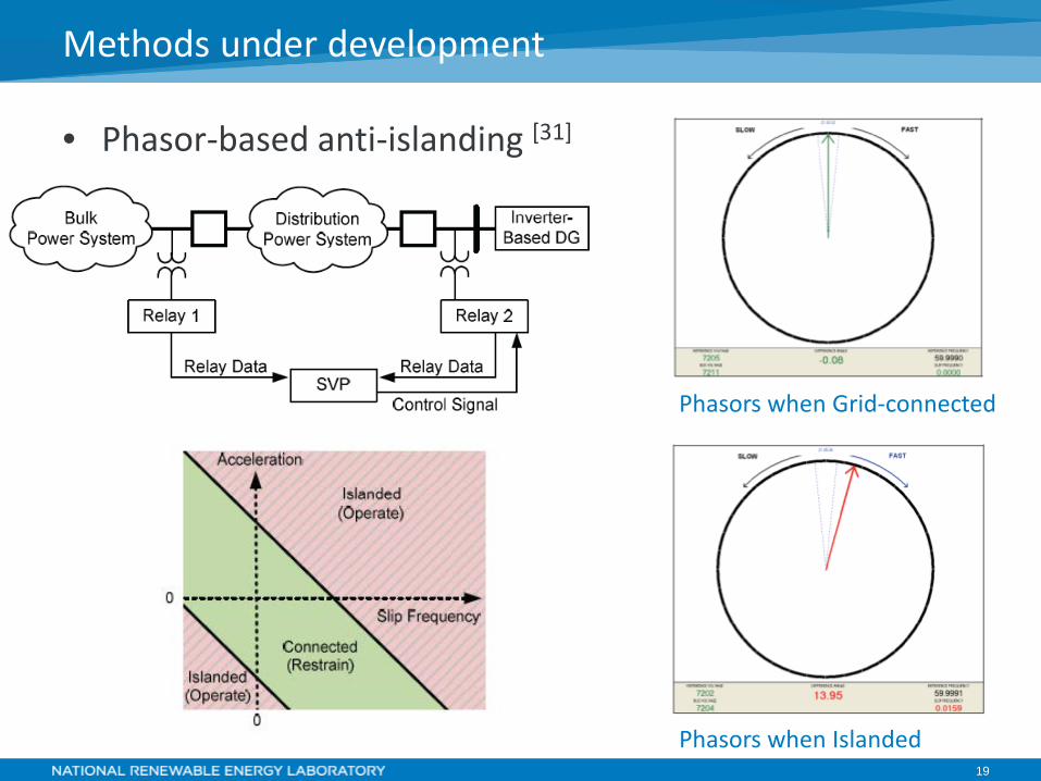
• Phasor-based anti-islanding [31]
Methods under development
Phasors when Grid-connected
Phasors when Islanded
20
Standard Unintentional Islanding Testing
21
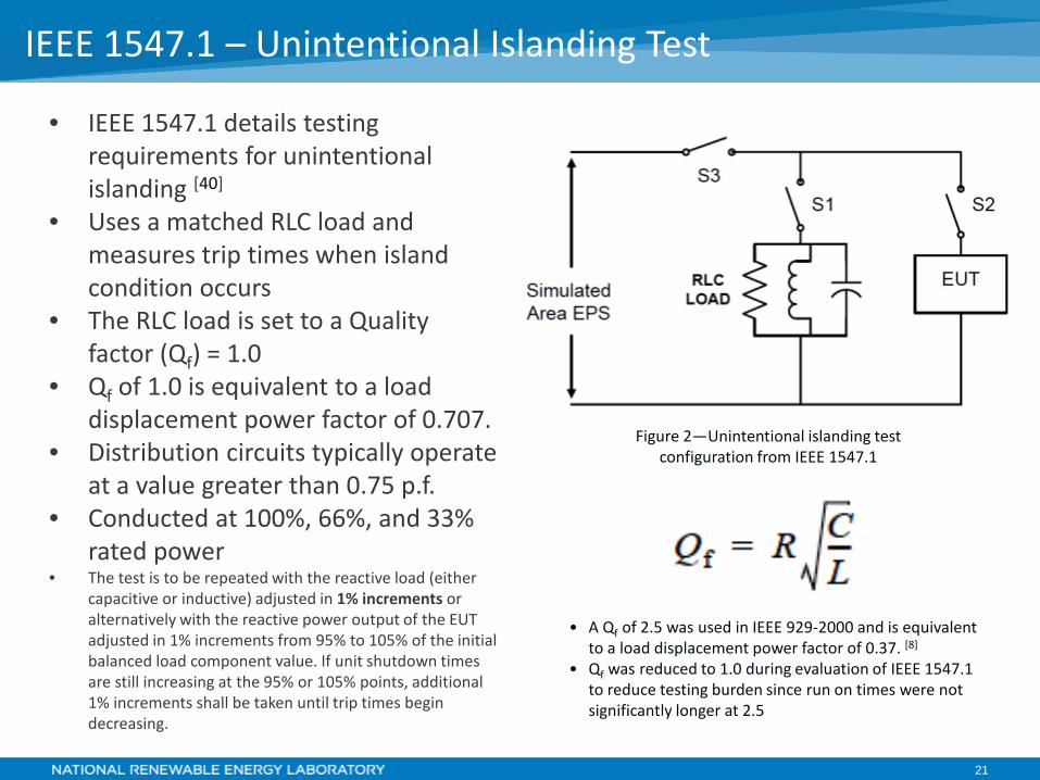
• IEEE 1547.1 details testing requirements for unintentional islanding [40]
• Uses a matched RLC load and measures trip times when island condition occurs
• The RLC load is set to a Quality factor (Qf) = 1.0
• Qf of 1.0 is equivalent to a load displacement power factor of 0.707.
• Distribution circuits typically operate at a value greater than 0.75 p.f.
• Conducted at 100%, 66%, and 33% rated power
• The test is to be repeated with the reactive load (either capacitive or inductive) adjusted in 1% increments or alternatively with the reactive power output of the EUT adjusted in 1% increments from 95% to 105% of the initial balanced load component value. If unit shutdown times are still increasing at the 95% or 105% points, additional 1% increments shall be taken until trip times begin decreasing.
IEEE 1547.1 – Unintentional Islanding Test
Figure 2—Unintentional islanding test configuration from IEEE 1547.1
• A Qf of 2.5 was used in IEEE 929-2000 and is equivalent to a load displacement power factor of 0.37. [8]
• Qf was reduced to 1.0 during evaluation of IEEE 1547.1 to reduce testing burden since run on times were not significantly longer at 2.5
22
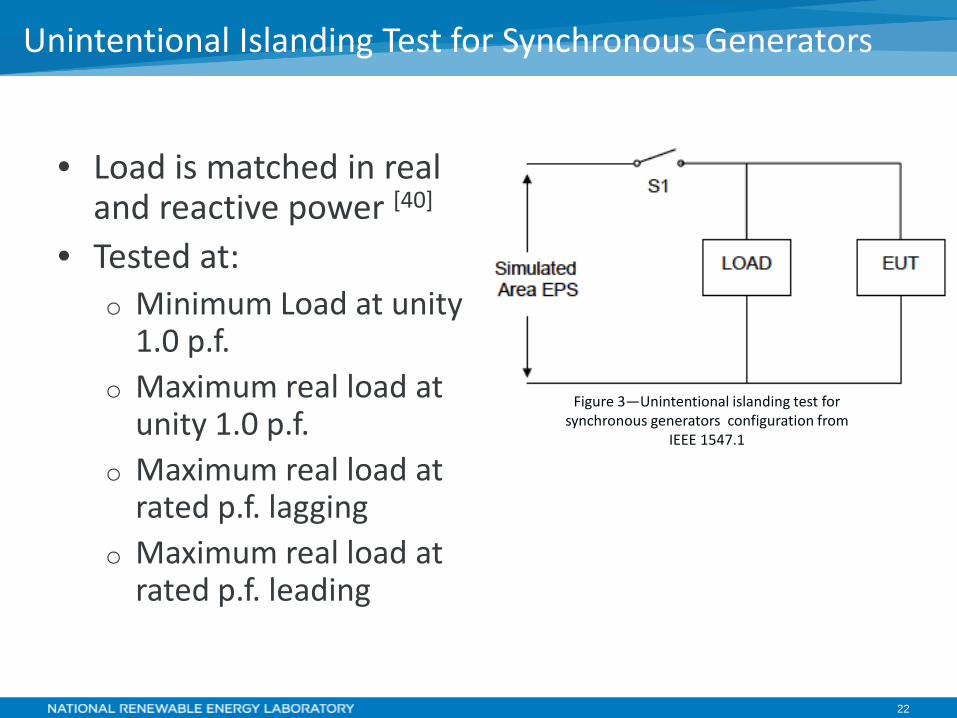
• Load is matched in real and reactive power [40]
• Tested at: o Minimum Load at unity
1.0 p.f. o Maximum real load at
unity 1.0 p.f. o Maximum real load at
rated p.f. lagging o Maximum real load at
rated p.f. leading
Unintentional Islanding Test for Synchronous Generators
Figure 3—Unintentional islanding test for synchronous generators configuration from
IEEE 1547.1
23
• To meet the unintentional islanding requirement in 1547, the DR installation may contain reverse or minimum import power-flow protection [40]
• Sensed between the point of DR connection and the PCC, it disconnects or isolates the DR if power flow from the area EPS to the local EPS reverses or falls below a set threshold.
• IEEE 1547.1 tests evaluate the magnitude and time of the reverse/minimum power flow protective device.
Reverse Power Flow (for unintentional islanding)
24
Advanced Testing
25
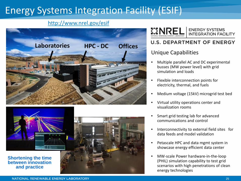
Energy Systems Integration Facility (ESIF)
Offices HPC - DC Laboratories Unique Capabilities • Multiple parallel AC and DC experimental
busses (MW power level) with grid simulation and loads
• Flexible interconnection points for electricity, thermal, and fuels
• Medium voltage (15kV) microgrid test bed
• Virtual utility operations center and visualization rooms
• Smart grid testing lab for advanced communications and control
• Interconnectivity to external field sites for data feeds and model validation
• Petascale HPC and data mgmt system in showcase energy efficient data center
• MW-scale Power hardware-in-the-loop (PHIL) simulation capability to test grid scenarios with high penetrations of clean energy technologies
Shortening the time between innovation
and practice
http://www.nrel.gov/esif
26
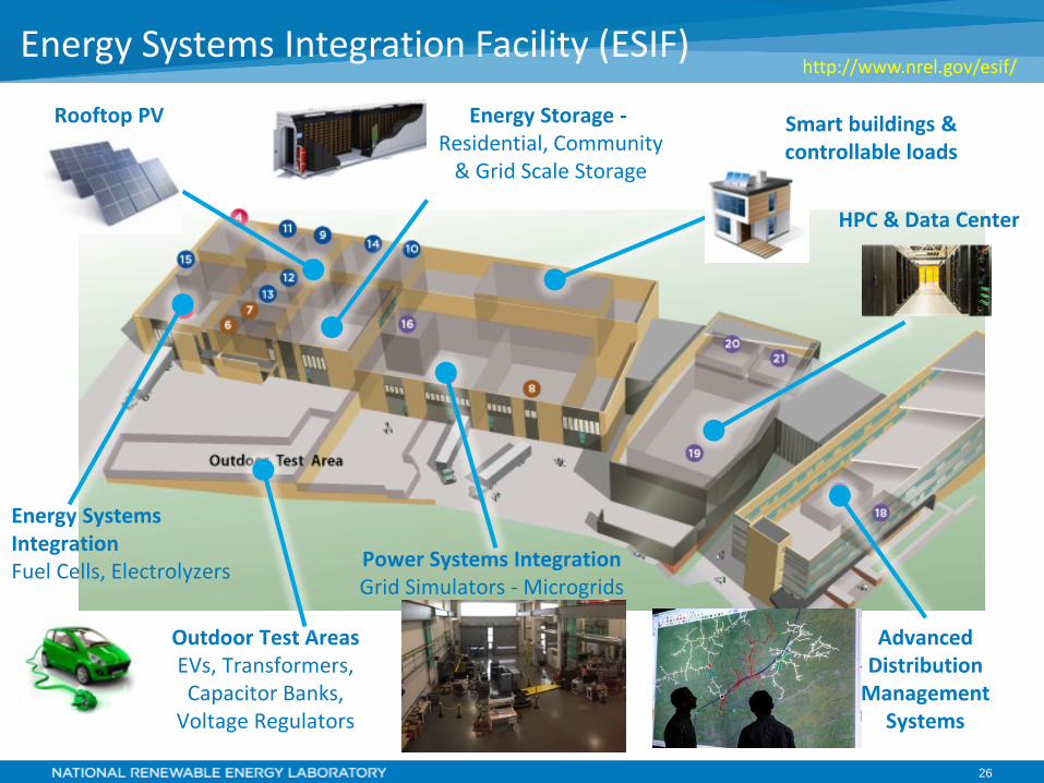
Energy Systems Integration Facility (ESIF)
Smart buildings & controllable loads
Power Systems Integration Grid Simulators - Microgrids
Energy Systems Integration Fuel Cells, Electrolyzers
Outdoor Test Areas EVs, Transformers, Capacitor Banks,
Voltage Regulators
Rooftop PV Energy Storage - Residential, Community
& Grid Scale Storage
HPC & Data Center
Advanced Distribution
Management Systems
http://www.nrel.gov/esif/
27
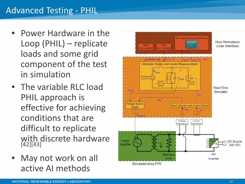
• Power Hardware in the Loop (PHIL) – replicate loads and some grid component of the test in simulation
• The variable RLC load PHIL approach is effective for achieving conditions that are difficult to replicate with discrete hardware [42][43]
• May not work on all active AI methods
Advanced Testing - PHIL
28
• Sandia Testing [44] – examined 4 inverters/single PCC (demonstrated that multiple inverters still meet 2 sec requirement).
• NREL Testing with SolarCity & HECO [45] - examined 1) the impacts of both grid support functions and 2) multi-inverter(3)/multi PCC islands on anti-islanding effectiveness. o Showed that with grid support functions (volt/var and
frequency/watt) enabled, the 2 sec requirement is still met.
o Showed that multiple PCCs did not cause trip times beyond 2 seconds (regardless of system topology)
o Results only valid on inverters/designs that were tested
Multiple Inverter Testing
29
Probability of Unintentional Islands
30
• To create an electrical island, the real and reactive power flows between DR and loads must be exactly matched
• What is the probability of this happening?
• IEA PVPS Task 5 – Study [46]
o The “benchmark” risk that already exists for network operators and customers is of the order of 10-6 per year for an individual person
o The risk of electric shock associated with islanding of PV systems under worst-case PV penetration scenarios to both network operators and customers is typically <10-9 per year
o Thus, the additional risk presented by islanding does not materially increase the risk that already exists as long as the risk is managed properly
o Balanced conditions occur very rarely for low, medium and high penetration levels of PV-systems.
• The probability that balanced conditions are present in the power network and that the power network is disconnected at that exact time is virtually zero.[47][48]
Probability of Islanding
31
Suggested Guidelines for Assessment of DG Unintentional Islanding Risk – Sandia Report [49]
• Cases in Which Unintentional Islanding can be Ruled Out o Aggregated AC rating of all DG within the potential island is
less than some fraction of the minimum real power load within the potential island
o Not possible to balance reactive power supply and demand within the potential island.
o DTT/PLCP is used • Cases in Which Additional Study May Be Considered
o Potential island contains large capacitors, and is tuned such that the power factor within a potential island is very close to 1.0
o Very large numbers of inverters o Inverters from several different manufacturers o Include both inverters and rotating generators
Guidelines for Assessment of DG Unintentional Islanding Risk
32
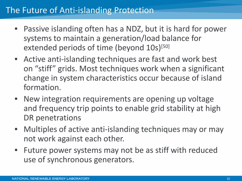
• Passive islanding often has a NDZ, but it is hard for power systems to maintain a generation/load balance for extended periods of time (beyond 10s)[50]
• Active anti-islanding techniques are fast and work best on “stiff” grids. Most techniques work when a significant change in system characteristics occur because of island formation.
• New integration requirements are opening up voltage and frequency trip points to enable grid stability at high DR penetrations
• Multiples of active anti-islanding techniques may or may not work against each other.
• Future power systems may not be as stiff with reduced use of synchronous generators.
The Future of Anti-islanding Protection
33
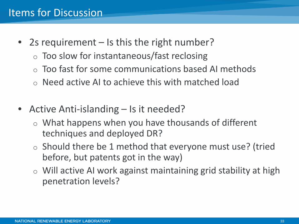
• 2s requirement – Is this the right number? o Too slow for instantaneous/fast reclosing o Too fast for some communications based AI methods o Need active AI to achieve this with matched load
• Active Anti-islanding – Is it needed?
o What happens when you have thousands of different techniques and deployed DR?
o Should there be 1 method that everyone must use? (tried before, but patents got in the way)
o Will active AI work against maintaining grid stability at high penetration levels?
Items for Discussion
34
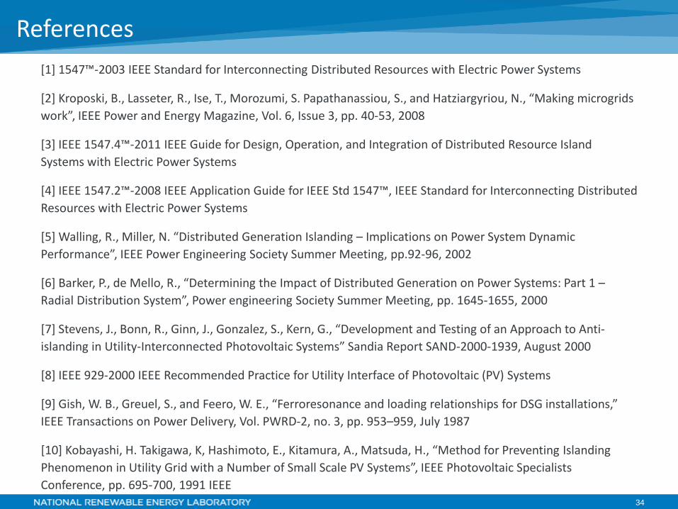
[1] 1547™-2003 IEEE Standard for Interconnecting Distributed Resources with Electric Power Systems
[2] Kroposki, B., Lasseter, R., Ise, T., Morozumi, S. Papathanassiou, S., and Hatziargyriou, N., “Making microgrids work”, IEEE Power and Energy Magazine, Vol. 6, Issue 3, pp. 40-53, 2008
[3] IEEE 1547.4™-2011 IEEE Guide for Design, Operation, and Integration of Distributed Resource Island Systems with Electric Power Systems
[4] IEEE 1547.2™-2008 IEEE Application Guide for IEEE Std 1547™, IEEE Standard for Interconnecting Distributed Resources with Electric Power Systems
[5] Walling, R., Miller, N. “Distributed Generation Islanding – Implications on Power System Dynamic Performance”, IEEE Power Engineering Society Summer Meeting, pp.92-96, 2002
[6] Barker, P., de Mello, R., “Determining the Impact of Distributed Generation on Power Systems: Part 1 – Radial Distribution System”, Power engineering Society Summer Meeting, pp. 1645-1655, 2000
[7] Stevens, J., Bonn, R., Ginn, J., Gonzalez, S., Kern, G., “Development and Testing of an Approach to Anti-islanding in Utility-Interconnected Photovoltaic Systems” Sandia Report SAND-2000-1939, August 2000
[8] IEEE 929-2000 IEEE Recommended Practice for Utility Interface of Photovoltaic (PV) Systems
[9] Gish, W. B., Greuel, S., and Feero, W. E., “Ferroresonance and loading relationships for DSG installations,” IEEE Transactions on Power Delivery, Vol. PWRD-2, no. 3, pp. 953–959, July 1987
[10] Kobayashi, H. Takigawa, K, Hashimoto, E., Kitamura, A., Matsuda, H., “Method for Preventing Islanding Phenomenon in Utility Grid with a Number of Small Scale PV Systems”, IEEE Photovoltaic Specialists Conference, pp. 695-700, 1991 IEEE
References
35
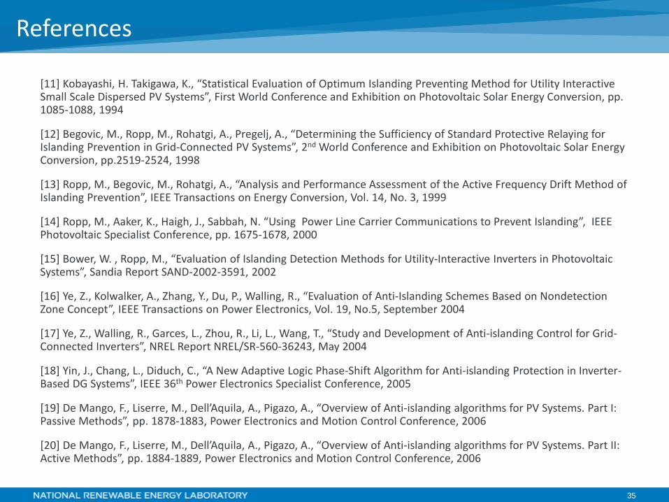
[11] Kobayashi, H. Takigawa, K., “Statistical Evaluation of Optimum Islanding Preventing Method for Utility Interactive Small Scale Dispersed PV Systems”, First World Conference and Exhibition on Photovoltaic Solar Energy Conversion, pp. 1085-1088, 1994
[12] Begovic, M., Ropp, M., Rohatgi, A., Pregelj, A., “Determining the Sufficiency of Standard Protective Relaying for Islanding Prevention in Grid-Connected PV Systems”, 2nd World Conference and Exhibition on Photovoltaic Solar Energy Conversion, pp.2519-2524, 1998
[13] Ropp, M., Begovic, M., Rohatgi, A., “Analysis and Performance Assessment of the Active Frequency Drift Method of Islanding Prevention”, IEEE Transactions on Energy Conversion, Vol. 14, No. 3, 1999
[14] Ropp, M., Aaker, K., Haigh, J., Sabbah, N. “Using Power Line Carrier Communications to Prevent Islanding”, IEEE Photovoltaic Specialist Conference, pp. 1675-1678, 2000
[15] Bower, W. , Ropp, M., “Evaluation of Islanding Detection Methods for Utility-Interactive Inverters in Photovoltaic Systems”, Sandia Report SAND-2002-3591, 2002
[16] Ye, Z., Kolwalker, A., Zhang, Y., Du, P., Walling, R., “Evaluation of Anti-Islanding Schemes Based on Nondetection Zone Concept”, IEEE Transactions on Power Electronics, Vol. 19, No.5, September 2004
[17] Ye, Z., Walling, R., Garces, L., Zhou, R., Li, L., Wang, T., “Study and Development of Anti-islanding Control for Grid-Connected Inverters”, NREL Report NREL/SR-560-36243, May 2004
[18] Yin, J., Chang, L., Diduch, C., “A New Adaptive Logic Phase-Shift Algorithm for Anti-islanding Protection in Inverter-Based DG Systems”, IEEE 36th Power Electronics Specialist Conference, 2005
[19] De Mango, F., Liserre, M., Dell’Aquila, A., Pigazo, A., “Overview of Anti-islanding algorithms for PV Systems. Part I: Passive Methods”, pp. 1878-1883, Power Electronics and Motion Control Conference, 2006
[20] De Mango, F., Liserre, M., Dell’Aquila, A., Pigazo, A., “Overview of Anti-islanding algorithms for PV Systems. Part II: Active Methods”, pp. 1884-1889, Power Electronics and Motion Control Conference, 2006
References
36
[21] Xu, W., Zhang, G., Li, C., Wang, W., Wang, W., Kliber, J., “A Power Line Signaling Based Technique for Anti-Islanding Protection of Distributed Generators – Part I: Scheme and Analysis”, IEEE Transactions on Power Delivery, Vo. 22, No.3, July 2007
[22] Hamzeh, M., Farhangi, S., Farhangi, B., “A New Control Method in PV Grid Connected Inverters for Anti-Islanding Protection by Impedance Monitoring”, 11th Workshop on Control and Modeling for Power Electronics, 2008
[23] Kunte, R., Gao, W., “Comparison and Review of Islanding Detection Techniques for Distributed Energy Resources,” 40th North American Power Symposium, 2008
[24] Chiang, W., Jou, H., Wu, J., Wu, K., Feng, Y., “Active islanding detection method for the grid-connected photovoltaic generation system”, Electric Power Systems Research, Vol 80, pp.372–379, 2009
[25] Wang, X., Freitas, W., Dinavahi, V., Xu, W., “Investigation of Positive Feedback Anti-Islanding Control for Multiple Inverter-Based Distributed Generator”, IEEE Transactions on Power Systems, Vol. 24, No.2, May 2009
[26] Timbus, A., Oudalov, A., Ho, C., “Islanding detection in smart grids”, IEEE Energy Conversion Congress and Exposition, 2010
[27] Velasco, D., Trujillo, C. Garcera, G., Figueres, E., “Review of anti-islanding techniques in distributed generators”, Renewable and Sustainable Energy Reviews, Vol. 14, pp. 1608–1614, 2010
[28] Yu, B., Matsui, M., Yu, G., “A review of current anti-islanding methods for photovoltaic power system”, Solar Energy, Bol.84, pp.745-754, 2010
[29] M. Hanif, M. Basu and K. Gaughan,: “A Discussion of Anti-islanding Protection Schemes Incorporated in a Inverter Based DG”, International Conference on Environment and Electrical Engineering (EEEIC) 2011, 10th International, 8-11 May 2011
[30] Teoh, W., Tan, C., “An Overview of Islanding Detection Methods in Photovoltaic Systems”, International Journal of Electrical, Computer, Energetic, Electronic and Communication Engineering Vol:5, No:10, 2011
References
37
[31] Mills-Price, M. Scharf, M., Hummel, S., Ropp, M. Joshi, D., Zweigle, G., Ravikumar, K., Flerchinger, B., “Solar Generation Control With Time-Synchronized Phasors” 64th Annual Conference for Protective Relay Engineers, 2011
[32] Ropp, M. “Assessment of the Universal Feasibility of Using power System Harmonics as a loss of Mains Detection for Distributed Energy Resources”, Report from Contract RDF-3-21
[33] Khamis, A., Shareef, H. Bizkevelci, E., Khatib, T., “A review of islanding detection techniques for renewable distributed generation systems”, Renewable and Sustainable Energy Reviews, Vol. 28, pp.483–493, 2013
[34] Ahmad, K., Selvaraj, J., Rahim, N., “A review of the islanding detection methods in grid-connected PV inverters”, Renewable and Sustainable Energy Reviews, Vol. 21, pp.756–766, 2013
[35] Datta, A., Saha, D, Ray, A., Das, P., “Anti-islanding selection for grid-connected solar photovoltaic system applications: A MCDM based distance approach”, Solar Energy, Vol 110, pp.519-532, 2014
[36] Guo, X., Xu, D., Wu, B, “Overview of anti-islanding US patents for grid-connected inverters”, Renewable and Sustainable Energy Reviews, Vol. 40, pp. 311–317, 2014
[38] Amendment 1 to 1547™-2003 IEEE Standard for Interconnecting Distributed Resources with Electric Power Systems
[39] PG&E Transmission Interconnection Handbook – Appendix F: Telemetering and Transfer Trip for Transmission Generation Entities, 2014, http://www.pge.com/includes/docs/pdfs/shared/rates/tariffbook/ferc/tih/app_f.pdf
[40] 1547.1™-2005 IEEE Standard Conformance Test Procedures for Equipment Interconnecting Distributed Resources with Electric Power Systems
References
38
[41] 1547.1™-2005 IEEE Standard Conformance Test Procedures for Equipment Interconnecting Distributed Resources with Electric Power Systems
[42] Lundstrom, B., Mather, B., Shirazi, M., Coddington, M., “Implementation and Validation of Advanced Unintentional Islanding Testing Using Power Hardware-in-the-Loop (PHIL) Simulation”, IEEE 39th Photovoltaic Specialists Conference (PVSC), pp.3141-3146, 2013
[43] Schoder,K., Langston, J., Hauer, J., Bogdan, F., Steurer, M., Mather, B., “Power Hardware-in-the-Loop-Based Anti-Islanding Evaluation and Demonstration”, NREL Report NREL/TP-5D00-64241, October 2015
[44] Gonzalez, S., Ropp, M., Fresquez, A., Montoya, M., “Multi-PV inverter Utility Interconnection Evaluation”, 37th IEEE Photovoltaic Specialists Conference (PVSC), 2011
[45] Hoke, A., Nelson, A., Miller, B., Chakraborty, S., Bell, F., McCarty, M., “Experimental Evaluation of PV Inverter Anti-Islanding with Grid Support Functions in Multi-Inverter Island Scenarios”, NREL Report NREL/TP-5D00-66732, July 2016
[46] Cullen, N., Thornycroft, J., Collinson, A., “Risk Analysis of Islanding of Photovoltaic Power Systems Within Low Voltage Distribution Networks”, IEA-PVPS Publication, March 2002
[47] Verhoeven, B., Probability of islanding in Utility Networks due to grid connected photovoltaic power system”, IEA-PVPS Publication, Report IEA-PVPS T5-07:2002, September 2002
[48] Woyte, A., DeBrabandere, K., Van Dommelen, D., Belmans, R., Nijs, J., “International Harmonization of Grid Connection Guidelines: Adequate Requirements for the Prevention of unintentional Islanding”, Progress in Photovoltaics: Research and Applications, Vol. 11, pp. 407-424, 2003
[49] Ropp, M., Ellis, A., “Suggested Guidelines for Assessment of DG Unintentional Islanding Risk”, Sandia Report – SAND2012-1365, March 2013 Revision
[50] Ropp,M., Joshi, D., Cozine, S., Schutz, D., “The Future Role of Passive Methods for Detecting Unintentional Island Formation”, Proceedings of the 48th Minnesota Power Systems Conference (MiPSyCon), November 2012
[51] GE Corporate R&D, “DG Power Quality, Protection and Reliability Case Studies Report”, NREL Report NREL/SR-560-34635, August 2003 http://www.nrel.gov/docs/fy03osti/34635.pdf
References

NREL … Providing Solutions to Grid
Integration Challenges
Thank You!
NREL is a national laboratory of the U.S. Department of Energy, Office of Energy efficiency and Renewable Energy operated by the Alliance for Sustainable Energy, LLC.
www.nrel.gov
NREL Power Systems Engineering Center


![Medical experts available to help 24a day hours 7a week ......Source: National Center for Injury Prevention and Control, Division of Unintentional Injury Prevention [1] Making Illinois](https://img.pdfslide.net/doc/110x75/5f3ab14d0c20e8028658a440/medical-experts-available-to-help-24a-day-hours-7a-week-source-national.jpg)