Embed Size (px)
Citation preview

PRIMERGY TX300 S4 Operating manual
Edition March 2008
Comments… Suggestions… Corrections…The User Documentation Department would like toknow your opinion of this manual. Your feedback helpsus optimize our documentation to suit your individual needs.
Feel free to send us your comments by e-mail to [email protected].
Certified documentation according to DIN EN ISO 9001:2000To ensure a consistently high quality standard anduser-friendliness, this documentation was created tomeet the regulations of a quality management system which complies with the requirements of the standardDIN EN ISO 9001:2000.
cognitas. Gesellschaft für Technik-Dokumentation mbHwww.cognitas.de
Copyright and TrademarksCopyright © 2008 Fujitsu Siemens Computers GmbH.
All rights are reserved.
Delivery subject to availability. The right to technical modification is reserved.
All hardware and software names used are trade names and/or trademarks of their respective manufacturers.
TX300 S4 Operating manual
Contents
1 Preface . . . . . . . . . . . . . . . . . . . . . . . . . . . . . . 7
1.1 Concept and target groups for this manual . . . . . . . . . . 7
1.2 Documentation overview . . . . . . . . . . . . . . . . . . . . 8
1.3 Features . . . . . . . . . . . . . . . . . . . . . . . . . . . . . . 9
1.4 Notational conventions . . . . . . . . . . . . . . . . . . . . 19
1.5 Technical data . . . . . . . . . . . . . . . . . . . . . . . . . 19
2 Installation steps, overview . . . . . . . . . . . . . . . . . . 23
3 Important information . . . . . . . . . . . . . . . . . . . . . 25
3.1 Safety instructions . . . . . . . . . . . . . . . . . . . . . . . 25
3.2 CE conformity . . . . . . . . . . . . . . . . . . . . . . . . . 32
3.3 FCC Class A Compliance Statement . . . . . . . . . . . . . 33
3.4 Transporting the server . . . . . . . . . . . . . . . . . . . . 34
3.5 Notes on installing in the rack . . . . . . . . . . . . . . . . . 35
3.6 Environmental protection . . . . . . . . . . . . . . . . . . . 36
4 Hardware installation . . . . . . . . . . . . . . . . . . . . . . 39
4.1 Unpacking the server . . . . . . . . . . . . . . . . . . . . . 40
4.2 Installing the floorstand model . . . . . . . . . . . . . . . . 40
4.3 Installing/removing the rack model . . . . . . . . . . . . . . 434.3.1 Installation in PRIMECENTER/DataCenter Rack . . . . . . . . 484.3.2 Installation in Classic Rack . . . . . . . . . . . . . . . . . . . 514.3.3 Installation in 3rd party racks . . . . . . . . . . . . . . . . . . 574.3.4 Inserting the server . . . . . . . . . . . . . . . . . . . . . . . 58
Operating manual TX300 S4
Contents
4.4 Connecting devices to the server . . . . . . . . . . . . . . . 64
4.5 Connecting the server to the mains . . . . . . . . . . . . . . 654.5.1 Using the cable clamp . . . . . . . . . . . . . . . . . . . . . . 66
4.6 Notes on connecting/disconnecting cables . . . . . . . . . . 68
5 Starting up and operation . . . . . . . . . . . . . . . . . . . . 69
5.1 Access to drives (floorstand model) . . . . . . . . . . . . . . 69
5.2 Controls and indicators . . . . . . . . . . . . . . . . . . . . . 715.2.1 Front of server . . . . . . . . . . . . . . . . . . . . . . . . . . 715.2.2 Rear of server . . . . . . . . . . . . . . . . . . . . . . . . . . . 76
5.3 Switching the server on and off . . . . . . . . . . . . . . . . 80
5.4 Configuring the server . . . . . . . . . . . . . . . . . . . . . 825.4.1 Configuring the PCI SAS controller with "Integrated Mirroring
Enhanced" . . . . . . . . . . . . . . . . . . . . . . . . . . . . 825.4.2 Configuring the PCI SAS controller with RAID functionality . . . 825.4.3 Configuration with ServerStart . . . . . . . . . . . . . . . . . . 835.4.4 Configuration without ServerStart . . . . . . . . . . . . . . . . 84
5.5 Cleaning the server . . . . . . . . . . . . . . . . . . . . . . . 85
6 Property and data protection . . . . . . . . . . . . . . . . . . 87
6.1 BIOS Setup security functions . . . . . . . . . . . . . . . . . 87
7 Troubleshooting and tips . . . . . . . . . . . . . . . . . . . . 89
7.1 Power-on indicator remains unlit . . . . . . . . . . . . . . . . 89
7.2 Server switches itself off . . . . . . . . . . . . . . . . . . . . 90
7.3 Screen remains blank . . . . . . . . . . . . . . . . . . . . . . 90
7.4 Flickering stripes on monitor screen . . . . . . . . . . . . . 91
7.5 No screen display or display drifts . . . . . . . . . . . . . . . 91
7.6 No mouse pointer displayed on screen . . . . . . . . . . . . 92
7.7 Unable to read from / write to floppy disk . . . . . . . . . . . 92
7.8 Incorrect date and time . . . . . . . . . . . . . . . . . . . . . 93
TX300 S4 Operating manual
Contents
7.9 Hard disk drive error messages at system boot . . . . . . . 93
7.10 Added drive reported as defective . . . . . . . . . . . . . . 94
7.11 Error message on screen . . . . . . . . . . . . . . . . . . . 94
8 CSS components . . . . . . . . . . . . . . . . . . . . . . . . 95
8.1 Hot-plug components . . . . . . . . . . . . . . . . . . . . . 958.1.1 Hot-plug power supply units . . . . . . . . . . . . . . . . . . . 968.1.1.1 Replacing the hot-plug power supply unit . . . . . . . . . . 968.1.2 Hot-plug hard disk drives . . . . . . . . . . . . . . . . . . . . 978.1.2.1 HDD module and dummy module . . . . . . . . . . . . . . 988.1.2.2 Handling hard disk drives and HDD modules . . . . . . . . 1008.1.2.3 Removing/installing the dummy module . . . . . . . . . . . 1018.1.2.4 Installing the HDD module . . . . . . . . . . . . . . . . . . 1028.1.2.5 Removing the HDD module . . . . . . . . . . . . . . . . . 1058.1.3 Replacing hot-plug CPU/system fans . . . . . . . . . . . . . . 107
8.2 Replacement of non-hot-plug components . . . . . . . . . 1108.2.1 Replacing a memory module . . . . . . . . . . . . . . . . . . 1118.2.1.1 Removing the air duct and riser card . . . . . . . . . . . . 1118.2.1.2 Removing a defective memory module . . . . . . . . . . . 1138.2.1.3 Installing a new memory module . . . . . . . . . . . . . . . 1148.2.1.4 Installing the riser card and air duct . . . . . . . . . . . . . 1158.2.2 Replacing the system fan . . . . . . . . . . . . . . . . . . . . 1178.2.3 Replacing the expansion card . . . . . . . . . . . . . . . . . . 119
8.3 Opening/closing the housing . . . . . . . . . . . . . . . . . 121
Abbreviations . . . . . . . . . . . . . . . . . . . . . . . . . . . . . . . 123
Index . . . . . . . . . . . . . . . . . . . . . . . . . . . . . . . . . . . . 129

TX300 S4 Operating manual 7
1 PrefaceThe PRIMERGY TX300 S4 server is an Intel-based server for mid-size and large companies. The server is suitable for use as a file server and also as an application, information or Internet server. It is available as a floorstand or rack model. The floorstand model can be converted to a rack model using an optional conversion kit.
Thanks to its highly developed hardware and software components, the PRIMERGY TX300 S4 server offers a high level of data security and availability. These components include hot-plug HDD modules and hot-plug power supply units, redundant system fans, and also the Server Management ServerView Suite, Prefailure Detection and Analysis (PDA) and Automatic Server Reconfig-uration and Restart (ASR&R).
Security functions in the BIOS-Setup and on the system board protect the data on the server against manipulation. Additional security is provided by the intrusion detection and the lockable drive cover on the floorstand model and the lockable rack door.
The rack model occupies 4 height units in the rack.
1.1 Concept and target groups for this manual
This operating manual describes how to install, set up and operate your server.
This operating manual is intended for those responsible for installing the hardware and ensuring that the system runs smoothly. It contains all the infor-mation you need to put your PRIMERGY TX300 S4 into operation.
To understand the various expansion options, you will need to be familiar with the fields of hardware and data transmission and you will require a basic knowledge of the underlying operating system.
8 Operating manual TX300 S4
Documentation overview Preface
1.2 Documentation overview
More information on your PRIMERGY TX300 S4 can be found in the following documents:
– “Quick Start Hardware - PRIMERGY TX300 S4” leaflet (only included as a printed copy)
– “Quick Start Software - Quick Installation Guide” leaflet (only included as a printed copy)
– “Safety notes and other important information” manual
– “Warranty” manual
– “Customer Self Service (CSS)” manual
– “Ergonomics” manual
– “Returning used devices” manual
– “Helpdesk” leaflet
– Technical manual for the system board D2529
– “PRIMERGY TX300 S4 Server Operating Manual”
– “PRIMERGY TX300 S4 Server Options Guide”
– “BIOS Setup V4.06 / FirstBIOS Desktop Pro V5.0 /TrustedCoreTM V6.0” manual
– “Integrated Mirroring User’s Guide”
I PRIMERGY manuals are available in PDF format on the ServerBooks DVD. The ServerBooks DVD is part of the ServerView Suite supplied with every server.
The PDF files of the manuals can also be downloaded free of charge from the Internet. The overview page showing the online documentation available on the Internet can be found using the URL: http://manuals.fujitsu-siemens.com. The PRIMERGY server documentation can be accessed using the Industry standard servers navigation option.
If you need a replacement copy of the ServerBooks DVD, send the details of your server to the following e-mail address: [email protected]
TX300 S4 Operating manual 9
Preface Features
Further sources of information:
– Manual for the monitor– Documentation for boards and drives– Documentation for your operating system– Information files on your operating system
1.3 Features
Customer Self Service (CSS)
The Fujitsu Siemens Computers Customer Self Service (CSS) concept enables you to identify and replace the affected component yourself in the case of certain error scenarios.
In the CSS concept, you can replace the following components yourself in the event of an error:
– Hot-plug hard disk drives
– Hot-plug power supply units
– Memory modules
– System fans
– Expansion cards
For information on replacing these components, see chapter “CSS compo-nents” on page 95.
CSS indicators on the control panel and on the back of the PRIMERGY server provide you with information if a CSS event arises (for more information on the behavior of these indicators, see chapter “Controls and indicators” on page 71 and the "Customer Self Service (CSS)" manual on the ServerBooks DVD).
You can also fit your server with a ServerView Local Service Panel, which enables you to identify the type of component affected by the error directly on the server (for more information, see the "Customer Self Service (CSS)" manual on the ServerBooks DVD).
In addition, CSS errors are displayed in ServerView S2, the server management software from Fujitsu Siemens Computers.
In the event of errors, ServerView S2 refers you directly to the affected component and its order information in the Illustrated Spares catalog of the server in question.
10 Operating manual TX300 S4
Features Preface
System board
The features of the system board are described in the technical manual for the system board D2529 for the hardware and in the “BIOS Setup” for the firmware.
TPM (optional)
The system board is optional equipped with a TPM (Trusted Platform Module) by the manufacturer. This module enables programs from third party manufac-turers to store key information (e.g. drive encryption using Windows Bitlocker Drive Encryption).
The TPM is activated via the BIOS system (for more information, refer to the Fujitsu Siemens Computers BIOS manual).
V CAUTION!
– When using the TPM, note the program descriptions provided by the third party manufacturers.
– You must also create a backup of the TPM content. To do this, follow the third party manufacturer's instructions. Without this backup, if the TPM or the system board is faulty you will not be able to access your data.
– If a failure occurs, please inform your service about the TPM activation before it takes any action, and be prepared to provide them with your backup copies of the TPM content.
PCI slots
The server has one standard PCI slot and six PCI express slots. Of these six PCI express slots, four are x4 slots and two potential x8 slots. The capacity of the two x8 slots depends on how all the PCI express slots are filled (see System Board manual D2529).
TX300 S4 Operating manual 11
Preface Features
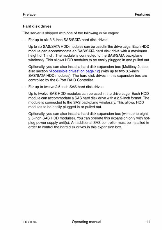
Hard disk drives
The server is shipped with one of the following drive cages:
– For up to six 3.5-inch SAS/SATA hard disk drives:
Up to six SAS/SATA HDD modules can be used in the drive cage. Each HDD module can accommodate an SAS/SATA hard disk drive with a maximum height of 1 inch. The module is connected to the SAS/SATA backplane wirelessly. This allows HDD modules to be easily plugged in and pulled out.
Optionally, you can also install a hard disk expansion box (Multibay 2, see also section “Accessible drives” on page 12) (with up to two 3.5-inch SAS/SATA HDD modules). The hard disk drives in this expansion box are controlled by the 8-Port RAID Controller.
– For up to twelve 2.5-inch SAS hard disk drives:
Up to twelve SAS HDD modules can be used in the drive cage. Each HDD module can accommodate a SAS hard disk drive with a 2.5-inch format. The module is connected to the SAS backplane wirelessly. This allows HDD modules to be easily plugged in or pulled out.
Optionally, you can also install a hard disk expansion box (with up to eight 2.5-inch SAS HDD modules). You can operate this expansion only with hot-plug power supply unit(s). An additional SAS controller must be installed in order to control the hard disk drives in this expansion box.
12 Operating manual TX300 S4
Features Preface
PCI SAS controller
To run the four SAS/SATA hard disk drives, the server is shipped with one of the following two PCI SAS controllers:
– PCI SAS controller with “Integrated Mirroring Enhanced” (IME)
IME supports RAID level 0, 1 and 1E configuration of the internal hard disk drives.
I A separate utility is available to the controller for IME configuration. Further information can be found in the “Integrated RAID for SAS User’s Guide” (on the ServerBooks DVD under “Controllers”).
– PCI SAS controller with MegaRAID functionality
RAID levels 0, 1, 10, 5, 50, 6 and 60 are supported. If required, a BBU (= battery backup unit) can save the memory content even if the power fails.
I A separate utility is available to the controller for RAID configuration. For further information, refer to the “SAS/SATA Controller MegaRAID 1064 / 1068 / 1078 Installation Guide” on the ServerBooks DVD (select “Controllers” from the menu).
Accessible drives
The server has three 3.5-inch bays.
You can use these bays as follows:
– You can equip the individual bays with CD/DVD drives or magnetic tape drives.
– In the bottom bay, you can install the Multibay 1 (FDD-DVD-LSD box). This box has bays for a slimline floppy disk drive, a slimline DVD drive and the ServerView Local Service Display.
– In the two lower bays, you can install the Multibay 2 (3.5’ HDD-DVD-LSD box). This box has bays for two additional 3.5-inch hard disk drives, a slimline DVD drive and the ServerView Local Service Display.
– You can install the Multibay 1 (FDD-DVD-LSD box) in the bottom bay (see above) and the expansion box for 2.5-inch SAS HDD modules in the two upper bays (see also section “Hard disk drives” on page 11).
TX300 S4 Operating manual 13
Preface Features
Power supply
In its basic configuration, the server has a fixed power supply unit.
Optionally, one or two redundant hot-plug power supply units are available. If one power supply unit fails, the second power supply unit in the redundant configuration ensures operation can continue uninterrupted. The defective power supply unit can be replaced during operation (for further details see section “Hot-plug power supply units” on page 96).
Both power supply unit versions automatically adjust to a mains voltage in the range of 100 V - 240 V.
Cooling
Each CPU has its own heat sink and a CPU fan.
The server is cooled by four system fans (redundant configuration).
If there are four system fans, each two form a redundant pair.
If one system fan in one redundant pair fails, the other fan ensures operation can continue uninterrupted. A defective system fan can be replaced during operation (for further details see “Replacing hot-plug CPU/system fans” on page 107).
The power supply fans are fitted in the respective power supply unit.
14 Operating manual TX300 S4
Features Preface
High level of availability and data security
When memory data is accessed, 1-bit errors in the main memory are identified and automatically corrected with the ECC (Error Correcting Code) method. The patented memory scrubbing function regularly starts up the EDC mechanism and thus ensures continuous data integrity.
The memory modules used support SDDC technology (Chipkill™), which also increases the effectiveness of the monitoring and correction of memory errors.
Memory Mirroring is also supported (requires four or eight memory modules). Memory Mirroring is roughly comparable to RAID level 1 for hard disk arrays. Memory modules are protected against failure by mirroring. The basic configu-ration requires four identical memory modules in two different banks.
ASR&R (Automatic Server Reconfiguration and Restart) restarts the system in case of an error and automatically “hides” the defective system components.
The PDA (Prefailure Detection and Analysis) technology from Fujitsu Siemens Computers analyzes and monitors all components that are critical for system reliability.
Optional RAID functionality of the PCI SAS controller supports RAID levels 0, 1, 10, 5, 50, 6 and RAID 60 and increases the availability of the system.
The hot-plug HDD modules offer increased availability.
TX300 S4 Operating manual 15
Preface Features
iRMC S2 with integrated service LAN port
I The features of the iRMC S2 Advanced Video Redirection and Remote Storage are available as an option.
The iRMC S2 (integrated Remote Management Controller) is a BMC with integrated service LAN port and expanded functionality that was previously only available with additional plug-in cards. In this way, the iRMC S2 enables complete control of PRIMERGY servers, regardless of system status, and thus particularly the control of PRIMERGY servers that are in the “out-of-band” system status.
Major functions supported by the iRMC S2 include the following:
● Browser access via iRMC's own Web server
● Secure communication (SSH, SSL)
● Power Management for the managed server (depending on its system status)
● Power Consumption Management
● Connecting virtual drives as remote storage
● Text-based and graphic console bypass (Advanced Video Redirection)
● Command Line Interface (CLP)
● Simple, interactive or script-based iRMC S2 configuration
● Customer Self Service (CSS)
● iRMC-s own user management
● Multi-computer, global iRMC user administration using an LDAP Directory Service
● Automatic network configuration via DNS / DHCP
● Power supply of the iRMC S2 via the system standby supply
● Full-coverage alarm management
● System Event Log (SEL) reading and processing
More information about the iRMC S2 can be found in the “iRMC S2 - integrated Remote Management Controller” manual.
16 Operating manual TX300 S4
Features Preface
Server management
Server management is implemented using the ServerView software supplied combined with PDA (Prefailure Detection and Analysis) technology from Fujitsu Siemens Computers. PDA reports the threat of a system error or overload at an early stage, allowing preventive measures to be taken.
ServerView enables the management of all PRIMERGY servers in the network via a central console. ServerView supports the following functions:
● Round-the-clock monitoring, regardless of server status
● High-performance, graphical console bypass (AVR) protected by HTTPS/SSL (128 bit)
● Remote storage via USB
● Remote power on (Wake On LAN)
● Intrusion detection in the floorstand model
● Temperature monitoring of the CPU and the surrounding area
● Monitoring of the utilization of the PCI buses
● Detailed status and error reports for bus systems, processors and main memory
● Watchdog timer for Automatic Server Reconfiguration and Restart (ASR&R) in the event of failure of memory modules or processors
● Power monitoring
● End-of-life monitoring of fans with prompt notification before failure
● Watchdog timer for operating system monitoring and application monitoring with ASR&R
Further information on the ServerView server management is provided in the associated documentation.
ServerStart
You can configure the PRIMERGY server quickly and precisely with the ServerStart software provided. User-guided menus are available for installing the server operating system (for further details see section “Configuring the server” on page 82).
TX300 S4 Operating manual 17
Preface Features
Service and support
PRIMERGY servers are service-friendly and modular, enabling quick and easy maintenance.
The handles and locks (touch point) on the different hot pluggable components are colored green to ensure simple and immediate recognition.
In order to avoid damage to components by incorrect handling when they are being installed and removed, green highlighting also identifies the areas of all components that can be touched without causing damage to the respective component.
PRIMERGY diagnostic LEDs fitted on the system board show which component on the board (memory module, CPU, fan) is not functioning properly.
The Flash EPROM program supplied with the Fujitsu Siemens Computers utilities supports a fast BIOS update.
With the iRMC (integrated Remote Management Controller) on the system board and the optional remote testing and diagnostic system ServerView Remote Management, the PRIMERGY TX300 S4 server can also be maintained and serviced remotely. This enables remote diagnosis for system analysis, remote configuration and remote restart should the operating system or hardware fail.
18 Operating manual TX300 S4
Features Preface
ServerView Remote Management
ServerView Remote Management is the remote management solution from Fujitsu Siemens Computers for PRIMERGY servers. ServerView Remote Management and the relevant hardware components integrated on the system board allow remote monitoring and maintenance as well as fast restoration of operation in the event of errors.
Remote monitoring and maintenance avoids time-consuming and costly on-site repairs and reduces service costs. This leads to a reduction in the total cost of ownership and an excellent return on investment for the remote management solution.
The administrator can access all system information and information from the sensors such as fan speeds or voltages via the iRMC S2's Web interface (see section “iRMC S2 with integrated service LAN port” on page 15). He can also start the text-based or graphic console bypass (Advanced Video Redirection, AVR) and get information about remote storage.
I The features of the iRMC S2 Advanced Video Redirection and Remote Storage are available as an option.
TX300 S4 Operating manual 19
Preface Notational conventions
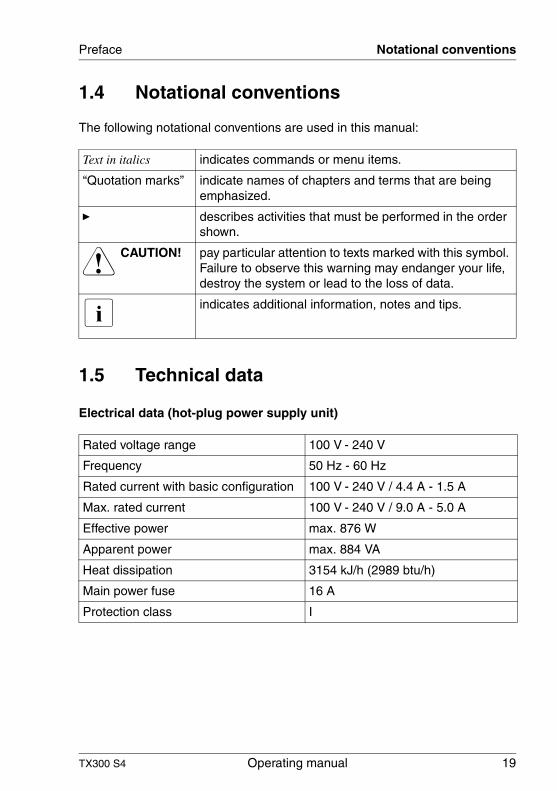
1.4 Notational conventions
The following notational conventions are used in this manual:
1.5 Technical data
Electrical data (hot-plug power supply unit)
Text in italics indicates commands or menu items.
“Quotation marks” indicate names of chapters and terms that are being emphasized.
Ê describes activities that must be performed in the order shown.
V CAUTION! pay particular attention to texts marked with this symbol. Failure to observe this warning may endanger your life, destroy the system or lead to the loss of data.
I indicates additional information, notes and tips.
Rated voltage range 100 V - 240 V
Frequency 50 Hz - 60 Hz
Rated current with basic configuration 100 V - 240 V / 4.4 A - 1.5 A
Max. rated current 100 V - 240 V / 9.0 A - 5.0 A
Effective power max. 876 W
Apparent power max. 884 VA
Heat dissipation 3154 kJ/h (2989 btu/h)
Main power fuse 16 A
Protection class I
20 Operating manual TX300 S4
Technical data Preface
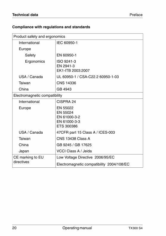
Compliance with regulations and standards
Product safety and ergonomics
International IEC 60950-1
Europe
Safety EN 60950-1
Ergonomics ISO 9241-3EN 2941-3EK1-ITB 2003:2007
USA / Canada UL 60950-1 / CSA-C22.2 60950-1-03
Taiwan CNS 14336
China GB 4943
Electromagnetic compatibility
International CISPRA 24
Europe EN 55022EN 55024EN 61000-3-2EN 61000-3-3ETS 300386
USA / Canada 47CFR part 15 Class A / ICES-003
Taiwan CNS 13438 Class A
China GB 9245 / GB 17625
Japan VCCI Class A / Jeida
CE marking to EU directives
Low Voltage Directive 2006/95/EC
Electromagnetic compatibility 2004/108/EC
TX300 S4 Operating manual 21
Preface Technical data
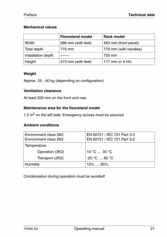
Mechanical values
Weight
Approx. 25 - 40 kg (depending on configuration).
Ventilation clearance
At least 200 mm on the front and rear.
Maintenance area for the floorstand model
1.2 m2 on the left side. Emergency access must be assured.
Ambient conditions
Condensation during operation must be avoided!
Floorstand model Rack model
Width 286 mm (with feet) 483 mm (front panel)
Total depth 775 mm 770 mm (with handles)
Installation depth ------- 735 mm
Height 473 mm (with feet) 177 mm or 4 HU
Environment class 3K2Environment class 2K2
EN 60721 / IEC 721 Part 3-3EN 60721 / IEC 721 Part 3-2
Temperature:
Operation (3K2) 10 °C .... 35 °C
Transport (2K2) -25 °C .... 60 °C
Humidity 10% .... 85%
22 Operating manual TX300 S4
Technical data Preface
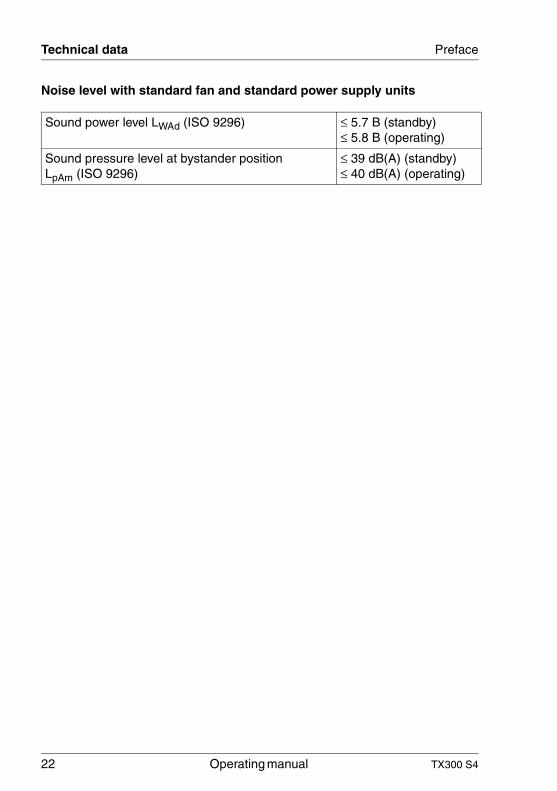
Noise level with standard fan and standard power supply units
Sound power level LWAd (ISO 9296) ≤ 5.7 B (standby)≤ 5.8 B (operating)
Sound pressure level at bystander position LpAm (ISO 9296)
≤ 39 dB(A) (standby)≤ 40 dB(A) (operating)
TX300 S4 Operating manual 23
2 Installation steps, overviewThis chapter contains an overview of the steps necessary to install your server. Links guide you to sections where you can find more detailed information on the individual steps:
Ê First of all, it is essential that you familiarize yourself with the safety infor-mation in chapter “Important information” on page 25.
Ê Unpack the system, check the contents of the package for visible transport damage and check whether the items delivered correspond to the details on the delivery note (see section “Unpacking the server” on page 40).
Ê Transport the server to the place where you want to install it.
Ê Make sure that all necessary manuals (see “Documentation overview” on page 8) are available; print out the PDF files if required.
Ê There can be additional ordered bulk components delivered with the server. For mounting refer to the original component documentation.
Ê Set up the floorstand model (see section “Installing the floorstand model” on page 40) or install the rack model in the rack (see section “Installing/removing the rack model” on page 43).
Ê Wire the server. Follow the instructions in the sections “Connecting devices to the server” on page 64 and “Notes on connecting/disconnecting cables” on page 68.
Ê Connect the server to the mains (see section “Connecting the server to the mains” on page 65).
Ê Familiarize yourself with the controls and indicators on the front and rear of the server (see section “Controls and indicators” on page 71).
24 Operating manual TX300 S4
Installation steps, overview
Ê Configure the server and install the desired operating system and applica-tions. The following options are available:
– Remote configuration and installation with ServerStart:
The ServerStart DVD supplied allows you to conveniently configure the server and install the operating system.
Details on how to operate ServerStart, as well as some additional infor-mation, can be found in the “PRIMERGY ServerView Suite - ServerStart” manual.
Configuration information can also be found in section “Configuration with ServerStart” on page 83.
– Local configuration and installation with or without ServerStart (see section “Configuration with ServerStart” on page 83 or section “Configu-ration without ServerStart” on page 84).
I You will find more information on installing the server remotely or locally in the ServerStart manual. This manual contains the instal-lation steps (“Quick Step Guide”). A corresponding file in PDF format is included on the ServerBooks DVD.
TX300 S4 Operating manual 25
3 Important informationIn this chapter you will find essential information regarding safety when working on your server.
3.1 Safety instructions
I The following safety instructions are also provided in the manual “Safety notes and other important information”.
This device meets the relevant safety regulations for IT equipment. If you have any questions about whether you can install the server in the intended environment, please contact your sales outlet or our customer service team.
V CAUTION!
● The actions described in this manual should only be performed by technical specialists.
● Repairs to the device that do not relate to CSS failures must only be carried out by service personnel. Please note that unauthorized inter-ference with the system will void the warranty and exempt the manufacturer from all liability.
● Any failure to observe the guidelines in this manual, and any improper repairs could expose the user to risks (electric shock, energy hazards, fire hazards) or damage the equipment.
26 Operating manual TX300 S4
Safety instructions Important information
Before starting up
V CAUTION!
● During installation and before operating the device, observe the instructions on environmental conditions for your device.
● If the device is brought in from a cold environment, condensation may form both inside and on the outside of the device.
Wait until the device has acclimatized to room temperature and is absolutely dry before starting it up. Material damage may be caused to the device if this requirement is not observed.
● Transport the device only in the original packaging or in packaging that protects it from knocks and jolts.
Installation and operation
V CAUTION!
● This unit should not be operated in ambient temperatures above 35 °C.
● If the unit is integrated into an installation that draws power from an industrial power supply network with an IEC309 connector, the power supply's fuse protection must comply with the requirements for non-industrial power supply networks for type A connectors.
● The unit automatically adjusts itself to a mains voltage in a range of 100 V - 240 V. Ensure that the local mains voltage lies within these limits.
● This device must only be connected to properly grounded shock-proof sockets or insulated sockets of the rack's internal power supply with tested and approved power cables.
● Ensure that the device is connected to a grounded shockproof socket close to the device.
TX300 S4 Operating manual 27
Important information Safety instructions
V CAUTION!
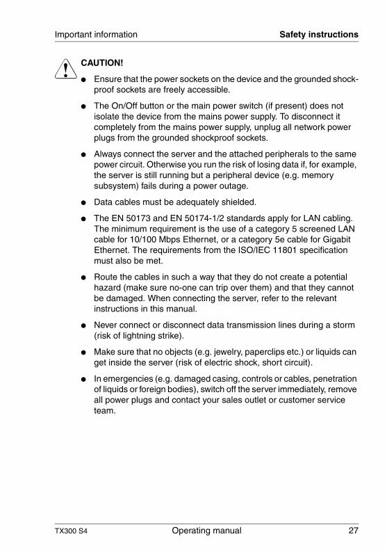
● Ensure that the power sockets on the device and the grounded shock-proof sockets are freely accessible.
● The On/Off button or the main power switch (if present) does not isolate the device from the mains power supply. To disconnect it completely from the mains power supply, unplug all network power plugs from the grounded shockproof sockets.
● Always connect the server and the attached peripherals to the same power circuit. Otherwise you run the risk of losing data if, for example, the server is still running but a peripheral device (e.g. memory subsystem) fails during a power outage.
● Data cables must be adequately shielded.
● The EN 50173 and EN 50174-1/2 standards apply for LAN cabling. The minimum requirement is the use of a category 5 screened LAN cable for 10/100 Mbps Ethernet, or a category 5e cable for Gigabit Ethernet. The requirements from the ISO/IEC 11801 specification must also be met.
● Route the cables in such a way that they do not create a potential hazard (make sure no-one can trip over them) and that they cannot be damaged. When connecting the server, refer to the relevant instructions in this manual.
● Never connect or disconnect data transmission lines during a storm (risk of lightning strike).
● Make sure that no objects (e.g. jewelry, paperclips etc.) or liquids can get inside the server (risk of electric shock, short circuit).
● In emergencies (e.g. damaged casing, controls or cables, penetration of liquids or foreign bodies), switch off the server immediately, remove all power plugs and contact your sales outlet or customer service team.
28 Operating manual TX300 S4
Safety instructions Important information
V CAUTION!
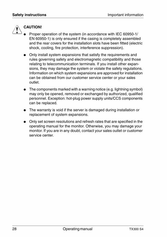
● Proper operation of the system (in accordance with IEC 60950-1/ EN 60950-1) is only ensured if the casing is completely assembled and the rear covers for the installation slots have been fitted (electric shock, cooling, fire protection, interference suppression).
● Only install system expansions that satisfy the requirements and rules governing safety and electromagnetic compatibility and those relating to telecommunication terminals. If you install other expan-sions, they may damage the system or violate the safety regulations. Information on which system expansions are approved for installation can be obtained from our customer service center or your sales outlet.
● The components marked with a warning notice (e.g. lightning symbol) may only be opened, removed or exchanged by authorized, qualified personnel. Exception: hot-plug power supply units/CCS components can be replaced.
● The warranty is void if the server is damaged during installation or replacement of system expansions.
● Only set screen resolutions and refresh rates that are specified in the operating manual for the monitor. Otherwise, you may damage your monitor. If you are in any doubt, contact your sales outlet or customer service center.
TX300 S4 Operating manual 29
Important information Safety instructions
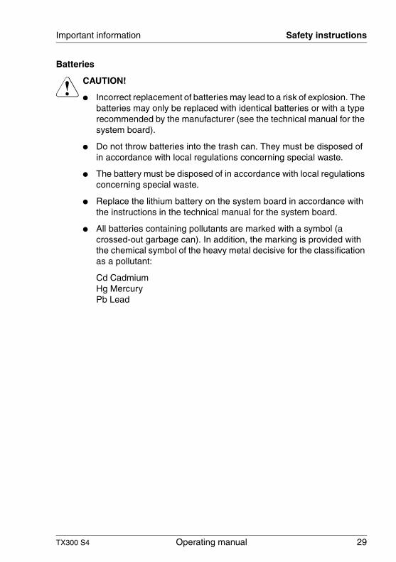
Batteries
V CAUTION!
● Incorrect replacement of batteries may lead to a risk of explosion. The batteries may only be replaced with identical batteries or with a type recommended by the manufacturer (see the technical manual for the system board).
● Do not throw batteries into the trash can. They must be disposed of in accordance with local regulations concerning special waste.
● The battery must be disposed of in accordance with local regulations concerning special waste.
● Replace the lithium battery on the system board in accordance with the instructions in the technical manual for the system board.
● All batteries containing pollutants are marked with a symbol (a crossed-out garbage can). In addition, the marking is provided with the chemical symbol of the heavy metal decisive for the classification as a pollutant:
Cd Cadmium Hg Mercury Pb Lead
30 Operating manual TX300 S4
Safety instructions Important information
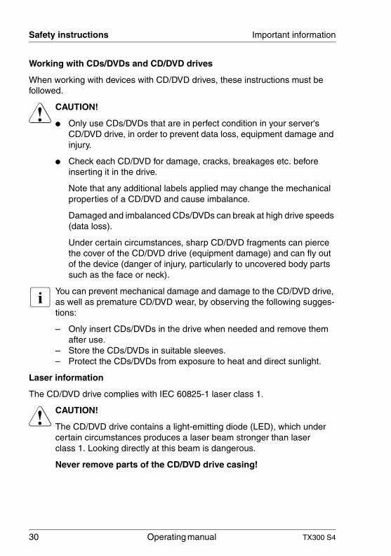
Working with CDs/DVDs and CD/DVD drives
When working with devices with CD/DVD drives, these instructions must be followed.
V CAUTION!
● Only use CDs/DVDs that are in perfect condition in your server's CD/DVD drive, in order to prevent data loss, equipment damage and injury.
● Check each CD/DVD for damage, cracks, breakages etc. before inserting it in the drive.
Note that any additional labels applied may change the mechanical properties of a CD/DVD and cause imbalance.
Damaged and imbalanced CDs/DVDs can break at high drive speeds (data loss).
Under certain circumstances, sharp CD/DVD fragments can pierce the cover of the CD/DVD drive (equipment damage) and can fly out of the device (danger of injury, particularly to uncovered body parts such as the face or neck).
I You can prevent mechanical damage and damage to the CD/DVD drive, as well as premature CD/DVD wear, by observing the following sugges-tions:
– Only insert CDs/DVDs in the drive when needed and remove them after use.
– Store the CDs/DVDs in suitable sleeves.– Protect the CDs/DVDs from exposure to heat and direct sunlight.
Laser information
The CD/DVD drive complies with IEC 60825-1 laser class 1.
V CAUTION!
The CD/DVD drive contains a light-emitting diode (LED), which under certain circumstances produces a laser beam stronger than laser class 1. Looking directly at this beam is dangerous.
Never remove parts of the CD/DVD drive casing!
TX300 S4 Operating manual 31
Important information Safety instructions
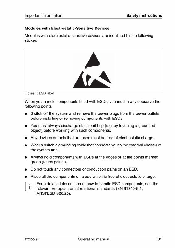
Modules with Electrostatic-Sensitive Devices
Modules with electrostatic-sensitive devices are identified by the following sticker:
Figure 1: ESD label
When you handle components fitted with ESDs, you must always observe the following points:
● Switch off the system and remove the power plugs from the power outlets before installing or removing components with ESDs.
● You must always discharge static build-up (e.g. by touching a grounded object) before working with such components.
● Any devices or tools that are used must be free of electrostatic charge.
● Wear a suitable grounding cable that connects you to the external chassis of the system unit.
● Always hold components with ESDs at the edges or at the points marked green (touch points).
● Do not touch any connectors or conduction paths on an ESD.
● Place all the components on a pad which is free of electrostatic charge.
I For a detailed description of how to handle ESD components, see the relevant European or international standards (EN 61340-5-1, ANSI/ESD S20.20).
32 Operating manual TX300 S4
CE conformity Important information
Other important information:
● During cleaning, observe the instructions in section “Cleaning the server” on page 85.
● Keep this operating manual and the other documentation (such as the technical manual, CD) close to the device. All documentation must be included if the equipment is passed on to a third party.
3.2 CE conformity
The system complies with the requirements of the EC directives 2004/108/EC regarding “Electromagnetic Compatibility” and 2006/95/EC “Low Voltage Directive”. This is indicated by the CE marking (CE = Communauté Européenne).
TX300 S4 Operating manual 33
Important information FCC Class A Compliance Statement
3.3 FCC Class A Compliance Statement
If there is an FCC statement on the device, then:
The following statement applies to the products covered in this manual, unless otherwise specified herein. The statement for other products will appear in the accompanying documentation.
NOTE:
This equipment has been tested and found to comply with the limits for a “Class A” digital device, pursuant to Part 15 of the FCC rules and meets all requirements of the Canadian Interference-Causing Equipment Standard ICES-003 for digital apparatus. These limits are designed to provide reasonable protection against harmful interference in a residential installation. This equipment generates, uses and can radiate radio frequency energy and, if not installed and used in strict accordance with the instructions, may cause harmful interference to radio communications. However, there is no warranty that inter-ference will not occur in a particular installation. If this equipment does cause harmful interference to radio or television reception, which can be determined by turning the equipment off and on, the user is encouraged to try to correct the interference by one or more of the following measures:
● Reorient or relocate the receiving antenna.
● Increase the separation between equipment and the receiver.
● Connect the equipment into an outlet on a circuit different from that to which the receiver is connected.
● Consult the dealer or an experienced radio/TV technician for help.
Fujitsu Siemens Computers is not responsible for any radio or television inter-ference caused by unauthorized modifications of this equipment or the substi-tution or attachment of connecting cables and equipment other than those specified by Fujitsu Siemens Computers. The correction of interferences caused by such unauthorized modification, substitution or attachment will be the responsibility of the user.
The use of shielded I/O cables is required when connecting this equipment to any and all optional peripheral or host devices. Failure to do so may violate FCC and ICES rules.
34 Operating manual TX300 S4
Transporting the server Important information
WARNING:
This is a class A product. In a domestic environment this product may cause radio interference in which case the user may be required to take adequate measures.
3.4 Transporting the server
V CAUTION!
Only transport the server in its original packaging or in packaging that protects it from impacts and jolts. Do not unpack the server until it is at its installation location.
If you need to lift or transport the server, ask other people to help you.
Never lift or carry the device by the handles on the front panel.
TX300 S4 Operating manual 35
Important information Notes on installing in the rack
3.5 Notes on installing in the rack
V CAUTION!
● For safety reasons, at least two people are required to install the rack model because of its weight and size.
● Never lift the server into the rack using the handles on the front panel.
● When connecting and disconnecting cables, observe the relevant instructions in the “Important Information” chapter of the technical manual for the corresponding rack. The technical manual is supplied with the corresponding rack.
● When installing the rack, make sure that the anti-tilt mechanism is correctly fitted.
● For safety reasons, no more than one unit may be removed from the rack at any one time during installation and maintenance work.
● If several units are simultaneously removed from the rack, there is a risk that the rack could tip over.
● The rack must be connected to the power supply by an authorized specialist (electrician).
● If the rack model is integrated into an installation that draws power from an industrial power supply network with an IEC309 type connector, the power supply's fuse protection must comply with the requirements for non-industrial power supply networks for the type A connector.

36 Operating manual TX300 S4
Environmental protection Important information
3.6 Environmental protection
Environmentally-friendly product design and development
This product has been designed in accordance with the Fujitsu Siemens Computers standard for “environmentally friendly product design and devel-opment”. This means that key factors such as durability, selection and labeling of materials, emissions, packaging, ease of dismantling and recycling have been taken into account.
This saves resources and thus reduces the harm done to the environment.
Energy-saving information
Devices that do not need to be constantly switched on should be switched off until they are needed as well as during long breaks and after completion of work.
Packaging information
Do not throw away the packaging. You may need it later for transporting the system. If possible, the equipment should only be transported in its original packaging.
Information on handling consumables
Please dispose of printer consumables and batteries in accordance with the applicable national regulations.
In accordance with EU directives, batteries must not be disposed of with unsorted domestic waste. They can be returned free of charge to the manufac-turer, dealer or an authorized agent for recycling or disposal.
All batteries containing pollutants are marked with a symbol (a crossed-out garbage can). They are also marked with the chemical symbol for the heavy metal that causes them to be categorized as containing pollutants:
Cd CadmiumHg MercuryPb Lead
TX300 S4 Operating manual 37
Important information Environmental protection
Labels on plastic casing parts
Please avoid sticking your own labels on plastic parts wherever possible, since this makes it difficult to recycle them.
Returns, recycling and disposal
Details regarding the return and recycling of devices and consumables within Europe can also be found in the “Returning used devices” manual, via your local Fujitsu Siemens Computers branch or from our recycling center in Paderborn:
Fujitsu Siemens ComputersRecycling CenterD-33106 Paderborn
Tel. +49 5251 8 18010
Fax +49 5251 8 18015
The device must not be disposed of with domestic waste. This device is labeled in compliance with European directive 2002/96/EC on waste electrical and electronic equipment (WEEE).
This directive sets the framework for returning and recycling used equipment and is valid across the EU. When returning your used device, please use the return and collection systems available to you. Further information can be found at www.fujitsu-siemens.com/recycling.

TX300 S4 Operating manual 39
4 Hardware installationV CAUTION!
● Follow the safety instructions in the chapter “Important information” on page 25.
● Do not expose the server to extreme environmental conditions (see “Ambient conditions” on page 21). Protect the server from dust, humidity and heat.
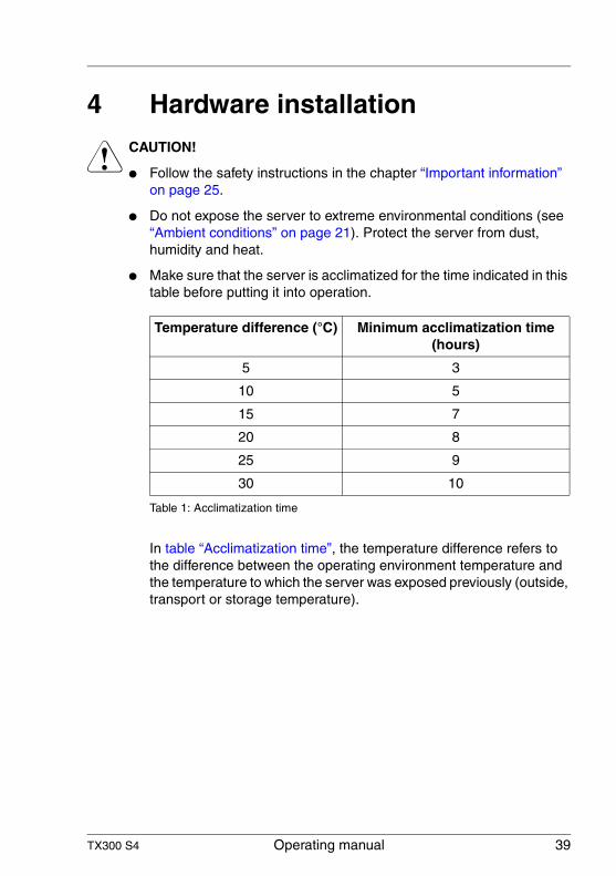
● Make sure that the server is acclimatized for the time indicated in this table before putting it into operation.
In table “Acclimatization time”, the temperature difference refers to the difference between the operating environment temperature and the temperature to which the server was exposed previously (outside, transport or storage temperature).
Temperature difference (°C) Minimum acclimatization time (hours)
5 3
10 5
15 7
20 8
25 9
30 10
Table 1: Acclimatization time
40 Operating manual TX300 S4
Unpacking the server Hardware installation
4.1 Unpacking the server
V CAUTION!
Follow the safety instructions in chapter “Important information” on page 25.
The server must always be lifted or carried by at least two people.
Do not unpack the server until it is at its installation location.
Ê Transport the server to the place where you want to set it up.
Ê Unpack all individual parts.
Keep the original packaging in case you want to transport the server again.
Ê Check the delivery for any damage during transport.
Ê Check whether the items delivered match the details on the delivery note.
The product name and serial number of the product can be found on the identi-fication rating plate.
Ê Notify your supplier immediately should you discover that the items delivered do not correspond to the delivery note.
4.2 Installing the floorstand model
I If you are not installing a PRIMERGY TX300 S4 floorstand model, skip this section and continue reading at section “Installing/removing the rack model” on page 43.
V CAUTION!
Please note the safety instructions in chapter “Important information” on page 25.
Ê Transport the server to the place where you want to set it up.
Ê Unpack the server (see “Unpacking the server” on page 40).
TX300 S4 Operating manual 41
Hardware installation Installing the floorstand model
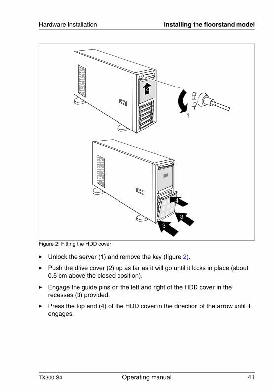
Figure 2: Fitting the HDD cover
Ê Unlock the server (1) and remove the key (figure 2).
Ê Push the drive cover (2) up as far as it will go until it locks in place (about 0.5 cm above the closed position).
Ê Engage the guide pins on the left and right of the HDD cover in the recesses (3) provided.
Ê Press the top end (4) of the HDD cover in the direction of the arrow until it engages.
42 Operating manual TX300 S4
Installing the floorstand model Hardware installation
Ê Install the server.
V CAUTION!
– The device must be protected from direct sunlight.– Ensure that there is enough unobstructed area around the server
for operating and servicing the device (see “Maintenance area for the floorstand model” on page 21).
– Access to the rear of the server must be assured so that other devices (e.g. memory subsystems) can be connected.
– The mains plug must be accessible easily and safely.– A clearance of at least 200 mm must be maintained in front of and
behind the system to ensure proper ventilation.
Ê Wire the server. Please take note of the section “Connecting devices to the server” on page 64 and the section “Notes on connecting/disconnecting cables” on page 68.
Ê Connect the system to the line voltage (see section “Connecting the server to the mains” on page 65).
TX300 S4 Operating manual 43
Hardware installation Installing/removing the rack model
4.3 Installing/removing the rack model
V CAUTION!
● Please observe the safety notes and notes on mounting into the rack in chapter “Important information” on page 25.
● Several people are needed to install / remove the server in the rack.
● The rack can tip over when more than one unit is removed.
● The server may not occupy the top height unit of the rack (42 HU Classic Rack, 38 HU/42HU PRIMECENTER Rack and/or DataCenter Rack), as otherwise no board and/or system fan can be replaced even with the slide-in module pulled out completely.
Rack requirements
The rack systems produced by Fujitsu Siemens Computers (PRIMECENTER Rack; DataCenter Rack and 19-Inch (Classic) rack) fully support the installation of PRIMERGY servers. Installation in most current rack systems from other manufacturers (3rd party racks) is also supported.
To accommodate the ventilation concept and ensure proper ventilation, any unused areas in the rack must be sealed using dummy covers.
The power is supplied via the multiple socket outlets fitted in the rack.
44 Operating manual TX300 S4
Installing/removing the rack model Hardware installation
The main features of the Fujitsu Siemens Computers GmbH rack systems are:
PRIMECENTER Rack
– Telescopic rails screwed to the front.
The rails have a linear alignment feature to ensure that they can be adjusted to different rack depths.
– Enhanced cable management in the lateral rack area.
DataCenter Rack
– Telescopic rails screwed to the front.
The rails have a linear alignment feature to ensure that they can be adjusted to different rack depths.
– Enhanced cable management in the lateral rack area.
19” (Classic) Rack
– Telescopic rails screwed to the sides.– Cable management using an articulated cable carrier.
The mounting of the rails in the different racks is described in the next sections.
Installation of the cable management is described in detail in the Technical Manual for the respective rack.
TX300 S4 Operating manual 45
Hardware installation Installing/removing the rack model
For rack systems from other manufacturers:
3rd party rack
Certain general conditions must be met:
– Installation dimensions (see the dimensions shown in figure 3 on page 46).
– Ensure that the safety mechanisms on the server, e.g. stoppers or retaining systems, are functioning correctly.
– The shape of the rack support uprights must ensure that the telescopic rails can be bolted at the front.
– Front bolted telescopic rails.
The rails have a linear alignment feature to ensure that they can be adjusted to different rack depths.
– No support for cable management system (included in installation kit).
1 Front of rack
2 Rear of rack
A Rack depth (comparison PRIMECENTER Rack 940/1000/1100 mm)
B Rack width (comparison PRIMECENTER Rack 700 mm)
C Clearance for 19” installation level
C1 Front 19” installation level
C2 Rear 19” installation level
D Cable routing area (cable area depth) and ventilation
E Space for front panel and ventilation
F Space for right and left support systems
P PRIMERGY rack installation depth
a1 Front left support upright
a2 Front right support upright
b1 Rear left support upright
b2 Rear right support upright
46 Operating manual TX300 S4
Installing/removing the rack model Hardware installation
Figure 3: Mechanical requirements
TX300 S4 Operating manual 47
Hardware installation Installing/removing the rack model
– The shape of the rack support uprights must ensure that the rails can be bolted to the front.
– Telescopic rails screwed to the front.
The rails have a linear alignment feature to ensure that they can be adjusted to different rack depths (710 - 785 mm).
– No support of the cable management.
– Climatic conditions:An unobstructed air intake in the rack front and air discharge in the rear cover of the rack are essential for ventilation of the installed server.
In principle the ventilation concept envisages that the necessary cooling is achieved by the horizontal self-ventilation of the installed devices (air flow from the front to the rear).
– Power supply:For installation in 3rd party racks, you must ensure that the appropriate socket strips are present.
48 Operating manual TX300 S4
Installing/removing the rack model Hardware installation
4.3.1 Installation in PRIMECENTER/DataCenter Rack
For installation in a PRIMECENTER/DataCenter Rack, the following parts are required:
– Support bracket– One support system on the left and one on the right (mounted) – M5 centering fixtures (screws with integrated plugwashers)
I – The descriptions and figures in this section refer to the current variable support.
– You can find general information regarding server installation in the rack in the technical manual for the appropriate rack.
When mounting the left telescopic rail in the corresponding rack, the supplied support bracket must first be mounted flush with the underside of the device on the rear left support upright.
Figure 4: Fitting the support bracket
Ê Position the support bracket at the corresponding height on the rear left support upright, (place knob(s) in corresponding hole(s) and secure it with the two supplied M5 centering fixtures.
Two versions of the support system are available:
– with two screw holes each front and rear
– with two retaining bolts rear and a screw hole front
TX300 S4 Operating manual 49
Hardware installation Installing/removing the rack model
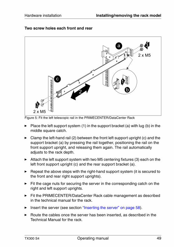
Two screw holes each front and rear
Figure 5: Fit the left telescopic rail in the PRIMECENTER/DataCenter Rack
Ê Place the left support system (1) in the support bracket (a) with lug (b) in the middle square catch.
Ê Clamp the left-hand rail (2) between the front left support upright (c) and the support bracket (a) by pressing the rail together, positioning the rail on the front support upright, and releasing them again. The rail automatically adjusts to the rack depth.
Ê Attach the left support system with two M5 centering fixtures (3) each on the left front support upright (c) and the rear support bracket (a).
Ê Repeat the above steps with the right-hand support system (it is secured to the front and rear right support uprights).
Ê Fit the cage nuts for securing the server in the corresponding catch on the right and left support uprights.
Ê Fit the PRIMECENTER/DataCenter Rack cable management as described in the technical manual for the rack.
Ê Insert the server (see section “Inserting the server” on page 58).
Ê Route the cables once the server has been inserted, as described in the Technical Manual for the rack.
a
c
2
3
3
2 x M5
2 x M5
b
1
50 Operating manual TX300 S4
Installing/removing the rack model Hardware installation
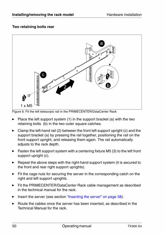
Two retaining bolts rear
Figure 6: Fit the left telescopic rail in the PRIMECENTER/DataCenter Rack
Ê Place the left support system (1) in the support bracket (a) with the two retaining bolts (b) in the two outer square catches.
Ê Clamp the left-hand rail (2) between the front left support upright (c) and the support bracket (a) by pressing the rail together, positioning the rail on the front support upright, and releasing them again. The rail automatically adjusts to the rack depth.
Ê Fasten the left support system with a centering fixture M5 (3) to the left front support upright (c).
Ê Repeat the above steps with the right-hand support system (it is secured to the front and rear right support uprights).
Ê Fit the cage nuts for securing the server in the corresponding catch on the right and left support uprights.
Ê Fit the PRIMECENTER/DataCenter Rack cable management as described in the technical manual for the rack.
Ê Insert the server (see section “Inserting the server” on page 58).
Ê Route the cables once the server has been inserted, as described in the Technical Manual for the rack.
a
c
2
3
1 x M5
b
1
TX300 S4 Operating manual 51
Hardware installation Installing/removing the rack model
4.3.2 Installation in Classic Rack
A special conversion kit (S26361-F1331-L200 without cable arm or S26361-F1331-L300 with cable arm) is needed for fitting in the Classic (19 inch 42/23 HE) rack:
– one support system on the left and one on the right (mounted)– Articulated cable guide– Protective hose for fiber channel fiber optic cable
I General information about rack installation can be found in the Technical Manual for the Classic (19 inch) rack and in the leaflet that accompanies the conversion kit.
Ê Mark the position of the attachment points for the telescopic rails and for the server (front panel) on the support uprights (four height units).
Ê Place the spring nuts for fixing the adapters in the groove on the support uprights at the marked fixing points.
Ê Place the M5 spring nuts for securing the server in the groove on the front faces of the front support uprights.
Ê Adjust the position of the nuts in the groove until they engage at the correct position.
52 Operating manual TX300 S4
Installing/removing the rack model Hardware installation
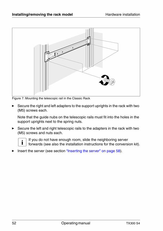
Figure 7: Mounting the telescopic rail in the Classic Rack
Ê Secure the right and left adapters to the support uprights in the rack with two (M5) screws each.
Note that the guide nubs on the telescopic rails must fit into the holes in the support uprights next to the spring nuts.
Ê Secure the left and right telescopic rails to the adapters in the rack with two (M5) screws and nuts each.
I If you do not have enough room, slide the neighboring server forwards (see also the installation instructions for the conversion kit).
Ê Insert the server (see section “Inserting the server” on page 58).
TX300 S4 Operating manual 53
Hardware installation Installing/removing the rack model
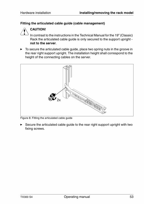
Fitting the articulated cable guide (cable management)
V CAUTION!
In contrast to the instructions in the Technical Manual for the 19” (Classic) Rack the articulated cable guide is only secured to the support upright - not to the server.
Ê To secure the articulated cable guide, place two spring nuts in the groove in the rear right support upright. The installation height shall correspond to the height of the connecting cables on the server.
Figure 8: Fitting the articulated cable guide
Ê Secure the articulated cable guide to the rear right support upright with two fixing screws.
54 Operating manual TX300 S4
Installing/removing the rack model Hardware installation
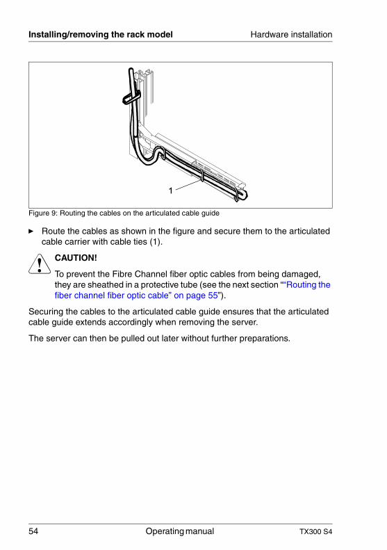
Figure 9: Routing the cables on the articulated cable guide
Ê Route the cables as shown in the figure and secure them to the articulated cable carrier with cable ties (1).
V CAUTION!
To prevent the Fibre Channel fiber optic cables from being damaged, they are sheathed in a protective tube (see the next section ““Routing the fiber channel fiber optic cable” on page 55”).
Securing the cables to the articulated cable guide ensures that the articulated cable guide extends accordingly when removing the server.
The server can then be pulled out later without further preparations.
TX300 S4 Operating manual 55
Hardware installation Installing/removing the rack model
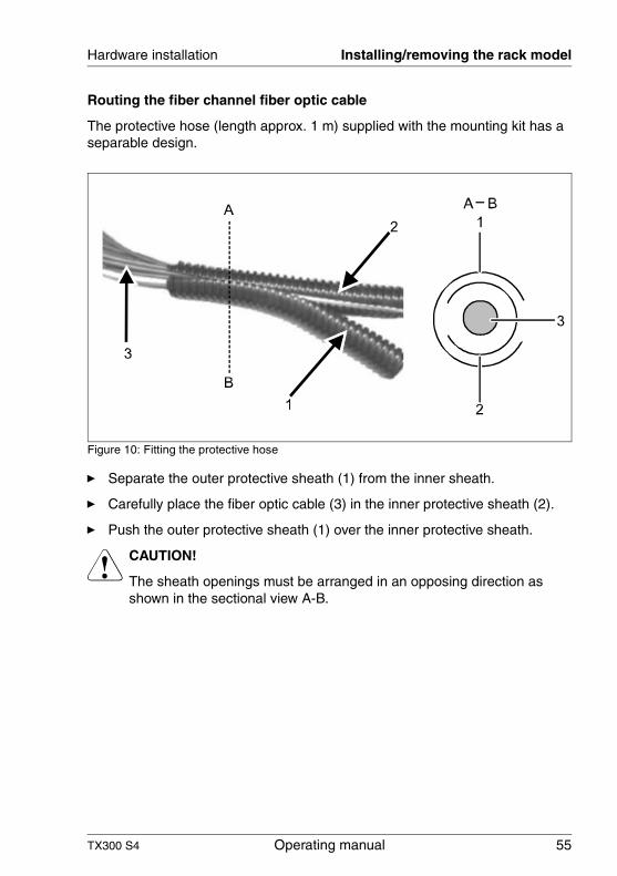
Routing the fiber channel fiber optic cable
The protective hose (length approx. 1 m) supplied with the mounting kit has a separable design.
Figure 10: Fitting the protective hose
Ê Separate the outer protective sheath (1) from the inner sheath.
Ê Carefully place the fiber optic cable (3) in the inner protective sheath (2).
Ê Push the outer protective sheath (1) over the inner protective sheath.
V CAUTION!
The sheath openings must be arranged in an opposing direction as shown in the sectional view A-B.
56 Operating manual TX300 S4
Installing/removing the rack model Hardware installation
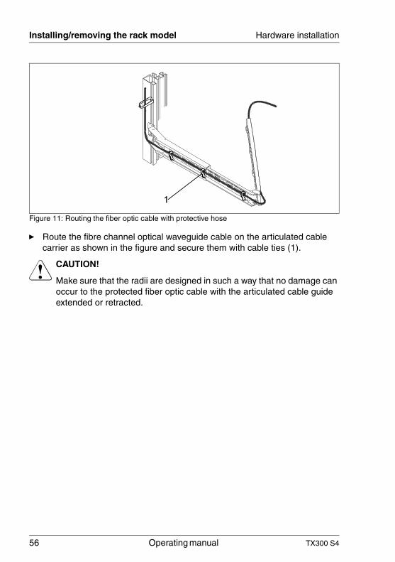
Figure 11: Routing the fiber optic cable with protective hose
Ê Route the fibre channel optical waveguide cable on the articulated cable carrier as shown in the figure and secure them with cable ties (1).
V CAUTION!
Make sure that the radii are designed in such a way that no damage can occur to the protected fiber optic cable with the articulated cable guide extended or retracted.
TX300 S4 Operating manual 57
Hardware installation Installing/removing the rack model
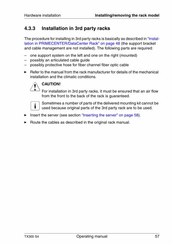
4.3.3 Installation in 3rd party racks
The procedure for installing in 3rd party racks is basically as described in “Instal-lation in PRIMECENTER/DataCenter Rack” on page 48 (the support bracket and cable management are not installed). The following parts are required:
– one support system on the left and one on the right (mounted)– possibly an articulated cable guide– possibly protective hose for fiber channel fiber optic cable
Ê Refer to the manual from the rack manufacturer for details of the mechanical installation and the climatic conditions.
V CAUTION!
For installation in 3rd party racks, it must be ensured that an air flow from the front to the back of the rack is guaranteed.
I Sometimes a number of parts of the delivered mounting kit cannot be used because original parts of the 3rd party rack are to be used.
Ê Insert the server (see section “Inserting the server” on page 58).
Ê Route the cables as described in the original rack manual.
58 Operating manual TX300 S4
Installing/removing the rack model Hardware installation
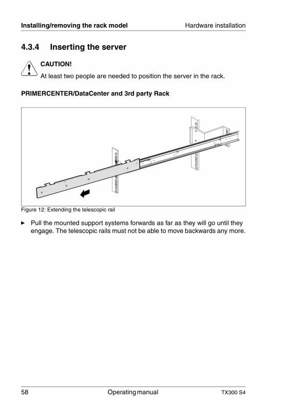
4.3.4 Inserting the server
V CAUTION!
At least two people are needed to position the server in the rack.
PRIMERCENTER/DataCenter and 3rd party Rack
Figure 12: Extending the telescopic rail
Ê Pull the mounted support systems forwards as far as they will go until they engage. The telescopic rails must not be able to move backwards any more.
TX300 S4 Operating manual 59
Hardware installation Installing/removing the rack model
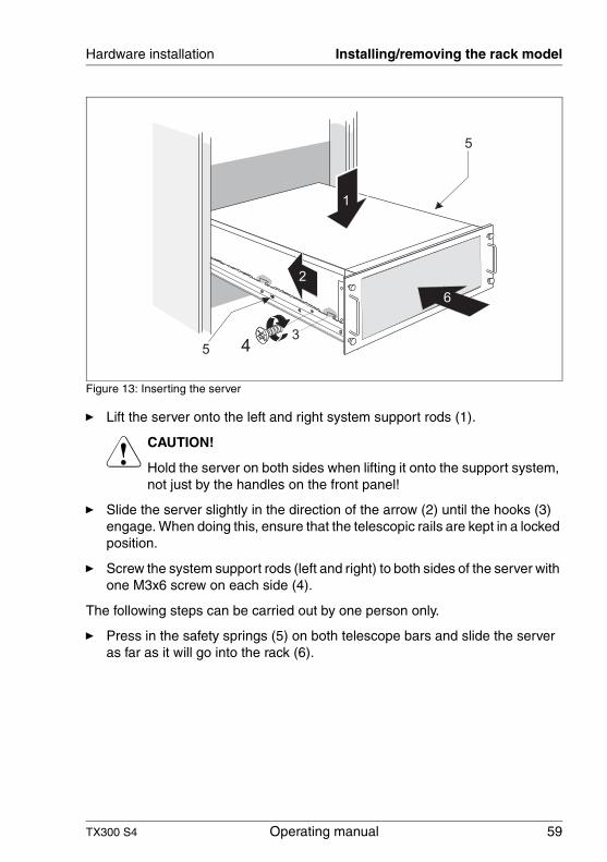
Figure 13: Inserting the server
Ê Lift the server onto the left and right system support rods (1).
V CAUTION!
Hold the server on both sides when lifting it onto the support system, not just by the handles on the front panel!
Ê Slide the server slightly in the direction of the arrow (2) until the hooks (3) engage. When doing this, ensure that the telescopic rails are kept in a locked position.
Ê Screw the system support rods (left and right) to both sides of the server with one M3x6 screw on each side (4).
The following steps can be carried out by one person only.
Ê Press in the safety springs (5) on both telescope bars and slide the server as far as it will go into the rack (6).
60 Operating manual TX300 S4
Installing/removing the rack model Hardware installation
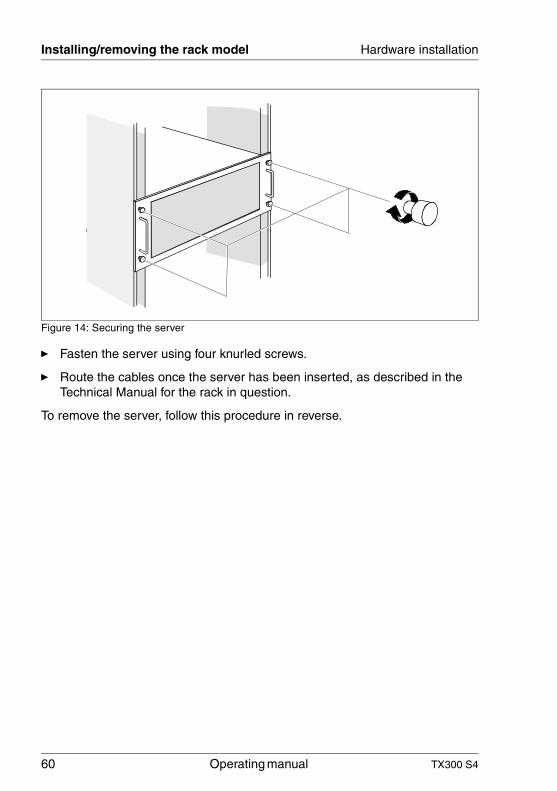
Figure 14: Securing the server
Ê Fasten the server using four knurled screws.
Ê Route the cables once the server has been inserted, as described in the Technical Manual for the rack in question.
To remove the server, follow this procedure in reverse.
TX300 S4 Operating manual 61
Hardware installation Installing/removing the rack model
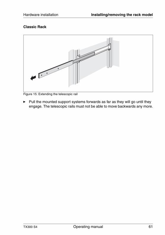
Classic Rack
Figure 15: Extending the telescopic rail
Ê Pull the mounted support systems forwards as far as they will go until they engage. The telescopic rails must not be able to move backwards any more.
62 Operating manual TX300 S4
Installing/removing the rack model Hardware installation
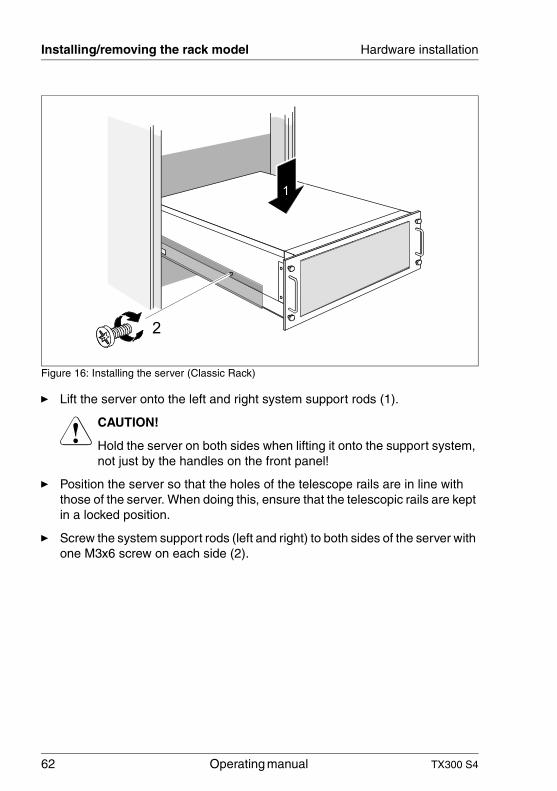
Figure 16: Installing the server (Classic Rack)
Ê Lift the server onto the left and right system support rods (1).
V CAUTION!
Hold the server on both sides when lifting it onto the support system, not just by the handles on the front panel!
Ê Position the server so that the holes of the telescope rails are in line with those of the server. When doing this, ensure that the telescopic rails are kept in a locked position.
Ê Screw the system support rods (left and right) to both sides of the server with one M3x6 screw on each side (2).
1
2
TX300 S4 Operating manual 63
Hardware installation Installing/removing the rack model
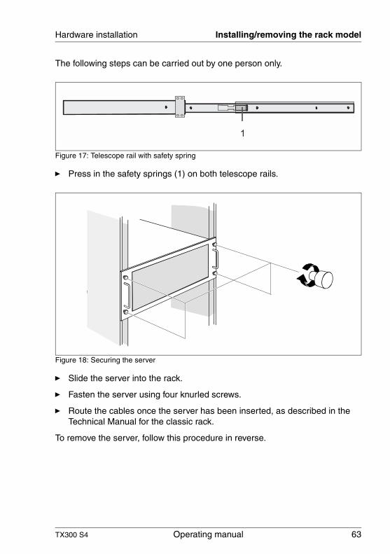
The following steps can be carried out by one person only.
Figure 17: Telescope rail with safety spring
Ê Press in the safety springs (1) on both telescope rails.
Figure 18: Securing the server
Ê Slide the server into the rack.
Ê Fasten the server using four knurled screws.
Ê Route the cables once the server has been inserted, as described in the Technical Manual for the classic rack.
To remove the server, follow this procedure in reverse.
64 Operating manual TX300 S4
Connecting devices to the server Hardware installation
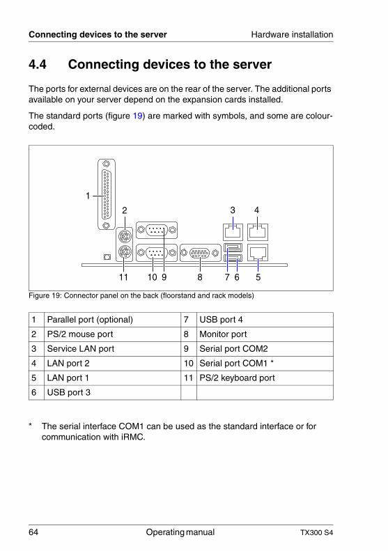
4.4 Connecting devices to the server
The ports for external devices are on the rear of the server. The additional ports available on your server depend on the expansion cards installed.
The standard ports (figure 19) are marked with symbols, and some are colour-coded.
Figure 19: Connector panel on the back (floorstand and rack models)
1 Parallel port (optional) 7 USB port 4
2 PS/2 mouse port 8 Monitor port
3 Service LAN port 9 Serial port COM2
4 LAN port 2 10 Serial port COM1 *
5 LAN port 1 11 PS/2 keyboard port
6 USB port 3
* The serial interface COM1 can be used as the standard interface or for communication with iRMC.
6 58 710 911
3 4
1
2
TX300 S4 Operating manual 65
Hardware installation Connecting the server to the mains
The corresponding indicators are explained in section “Rear of server” on page 76.
I Some of the devices connected require special software (e.g. drivers) (see documentation for the connected device).
Ê Connect the devices.
You can find an additional USB port on the front of the server (see figure 24 on page 71).
Connecting the keyboard, mouse and monitor
Ê Connect the monitor, the keyboard and the mouse to the standard ports of the server (see figure 19 on page 64).
Ê Connect the power cable of the monitor to a grounded mains outlet of the in-house mains and/or into the mains socket strip of the rack.
V CAUTION!
The rated current for the monitor can be found on the technical data label on the monitor or in the operating manual for the monitor.
4.5 Connecting the server to the mains
In its basic configuration level the server has a hot-plug power supply unit. A second hot-plug power supply unit can be added to achieve redundant power supply. If a defect occurs in one power supply unit, the respective other power supply unit ensures unimpaired further operation.
V CAUTION!
The server is automatically set to a mains voltage in the range 100 V -240 V. Make sure that your local mains voltage is within the range.
66 Operating manual TX300 S4
Connecting the server to the mains Hardware installation
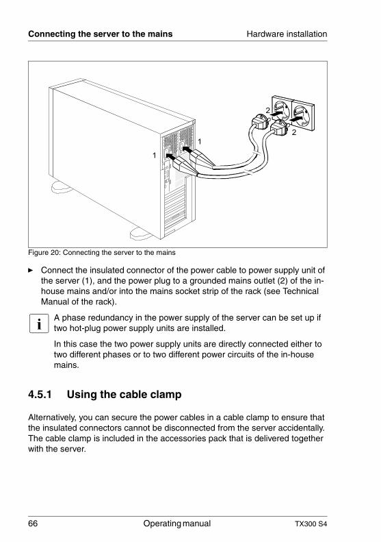
Figure 20: Connecting the server to the mains
Ê Connect the insulated connector of the power cable to power supply unit of the server (1), and the power plug to a grounded mains outlet (2) of the in-house mains and/or into the mains socket strip of the rack (see Technical Manual of the rack).
I A phase redundancy in the power supply of the server can be set up if two hot-plug power supply units are installed.
In this case the two power supply units are directly connected either to two different phases or to two different power circuits of the in-house mains.
4.5.1 Using the cable clamp
Alternatively, you can secure the power cables in a cable clamp to ensure that the insulated connectors cannot be disconnected from the server accidentally. The cable clamp is included in the accessories pack that is delivered together with the server.
1
1
2
2
TX300 S4 Operating manual 67
Hardware installation Connecting the server to the mains
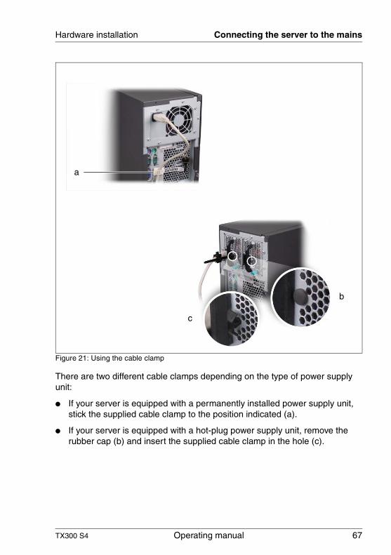
Figure 21: Using the cable clamp
There are two different cable clamps depending on the type of power supply unit:
● If your server is equipped with a permanently installed power supply unit, stick the supplied cable clamp to the position indicated (a).
● If your server is equipped with a hot-plug power supply unit, remove the rubber cap (b) and insert the supplied cable clamp in the hole (c).
a
c
b
68 Operating manual TX300 S4
Notes on connecting/disconnecting cables Hardware installation
4.6 Notes on connecting/disconnecting cables
V CAUTION!
Always read the documentation supplied with the device you wish to connect.
Never connect, or disconnect cables during a thunderstorm.
Never pull on a cable when disconnecting it. Always take hold of the cable by the plug.
Follow the sequence described below to connect or disconnect external devices to or from the server:
Connecting cables
Ê Turn off all power and equipment switches.
Ê Disconnect all power plugs from the grounded shockproof sockets.
Ê Connect all cables to the server and peripherals.
Ê Plug all data communication cables into the utility sockets.
Ê Plug all power cables into the grounded shockproof sockets.
Disconnecting cables
Ê Turn off all power and equipment switches.
Ê Disconnect all power plugs from the grounded shockproof sockets.
Ê Unplug all data communication cables from the utility sockets.
Ê Disconnect the relevant cables from the server and all the peripherals.
TX300 S4 Operating manual 69
5 Starting up and operationV CAUTION!
Follow the safety instructions in chapter “Important information” on page 25.
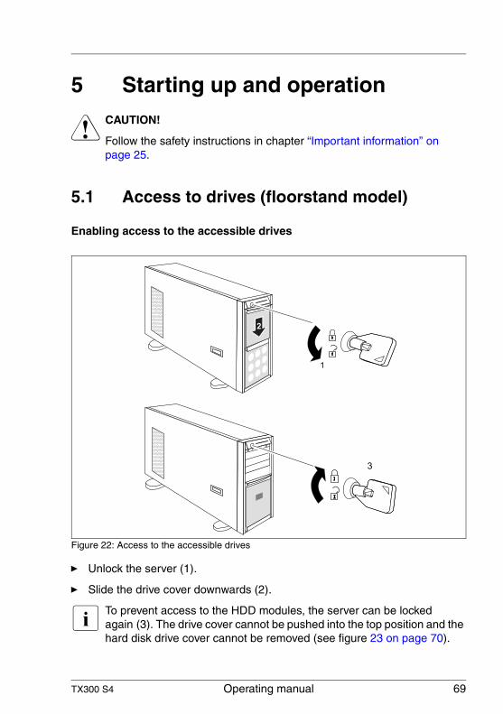
5.1 Access to drives (floorstand model)
Enabling access to the accessible drives
Figure 22: Access to the accessible drives
Ê Unlock the server (1).
Ê Slide the drive cover downwards (2).
I To prevent access to the HDD modules, the server can be locked again (3). The drive cover cannot be pushed into the top position and the hard disk drive cover cannot be removed (see figure 23 on page 70).
70 Operating manual TX300 S4
Access to drives (floorstand model) Starting up and operation
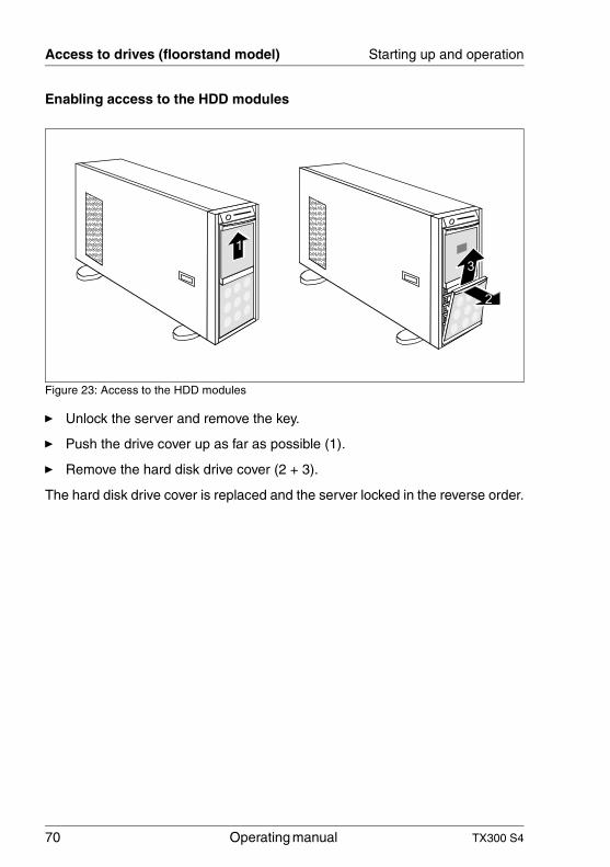
Enabling access to the HDD modules
Figure 23: Access to the HDD modules
Ê Unlock the server and remove the key.
Ê Push the drive cover up as far as possible (1).
Ê Remove the hard disk drive cover (2 + 3).
The hard disk drive cover is replaced and the server locked in the reverse order.
1
2
3
TX300 S4 Operating manual 71
Starting up and operation Controls and indicators
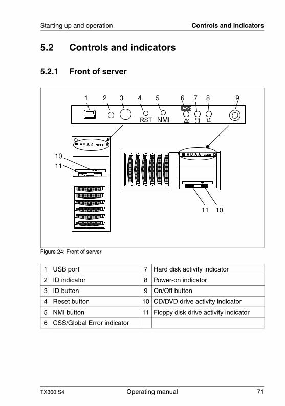
5.2 Controls and indicators
5.2.1 Front of server
Figure 24: Front of server
1 USB port 7 Hard disk activity indicator
2 ID indicator 8 Power-on indicator
3 ID button 9 On/Off button
4 Reset button 10 CD/DVD drive activity indicator
5 NMI button 11 Floppy disk drive activity indicator
6 CSS/Global Error indicator
!
!
1 2 3 4 5 6 7 8 9
1011
10
11
72 Operating manual TX300 S4
Controls and indicators Starting up and operation
Controls
Indicators on the control panel
On/Off button
When the system is switched off, it can be switched on again by pressing the On/Off button. When the system is operating, pressing the On/Off button will switch off the system.
I The On/Off button does not disconnect the server from the mains voltage. To disconnect from the mains completely, remove the power plug(s).
NMI NMI button
V CAUTION!
Do not press! Risk of loss of data!
The NMI button may only be used by service.
RST Reset button
Pressing the reset button reboots the system.
V CAUTION!
Risk of loss of data!
ID ID button
Lights up (blue) on the front and on the rear of the server when the ID button is pressed. The two ID indicators are synchronized.
Power-on indicator (two colors)
Lights up green when the server is switched ON.
Lights up orange when the server is switched OFF, but mains voltage is present (standby mode).
Hard disk activity indicator (green)
An internal drive (HDD or backup drive) is being accessed.
TX300 S4 Operating manual 73
Starting up and operation Controls and indicators
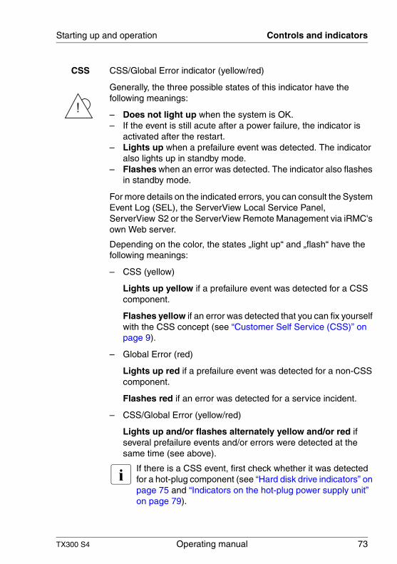
CSS CSS/Global Error indicator (yellow/red)
Generally, the three possible states of this indicator have the following meanings:
– Does not light up when the system is OK.– If the event is still acute after a power failure, the indicator is
activated after the restart.– Lights up when a prefailure event was detected. The indicator
also lights up in standby mode.– Flashes when an error was detected. The indicator also flashes
in standby mode.
For more details on the indicated errors, you can consult the System Event Log (SEL), the ServerView Local Service Panel, ServerView S2 or the ServerView Remote Management via iRMC's own Web server.
Depending on the color, the states „light up“ and „flash“ have the following meanings:
– CSS (yellow)
Lights up yellow if a prefailure event was detected for a CSS component.
Flashes yellow if an error was detected that you can fix yourself with the CSS concept (see “Customer Self Service (CSS)” on page 9).
– Global Error (red)
Lights up red if a prefailure event was detected for a non-CSS component.
Flashes red if an error was detected for a service incident.
– CSS/Global Error (yellow/red)
Lights up and/or flashes alternately yellow and/or red if several prefailure events and/or errors were detected at the same time (see above).
I If there is a CSS event, first check whether it was detected for a hot-plug component (see “Hard disk drive indicators” on page 75 and “Indicators on the hot-plug power supply unit” on page 79).
!
74 Operating manual TX300 S4
Controls and indicators Starting up and operation
Indicators on the drives
CD/DVD drive activity indicator
Lights up green when the storage medium is being accessed.
Floppy disk drive activity indicator
Lights up green when the storage medium is being accessed.
ID ID indicator (blue)
Lights up blue when the system has been selected by pressing the ID button. To deactivate, press the button again.
The ID indicator can also be activated via ServerView S2 and its status reported to ServerView.
TX300 S4 Operating manual 75
Starting up and operation Controls and indicators
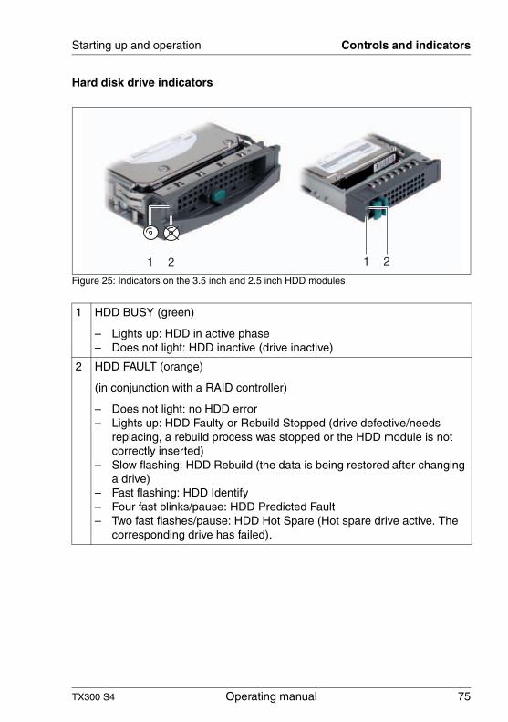
Hard disk drive indicators
Figure 25: Indicators on the 3.5 inch and 2.5 inch HDD modules
1 HDD BUSY (green)
– Lights up: HDD in active phase– Does not light: HDD inactive (drive inactive)
2 HDD FAULT (orange)
(in conjunction with a RAID controller)
– Does not light: no HDD error– Lights up: HDD Faulty or Rebuild Stopped (drive defective/needs
replacing, a rebuild process was stopped or the HDD module is not correctly inserted)
– Slow flashing: HDD Rebuild (the data is being restored after changing a drive)
– Fast flashing: HDD Identify– Four fast blinks/pause: HDD Predicted Fault– Two fast flashes/pause: HDD Hot Spare (Hot spare drive active. The
corresponding drive has failed).
1 2 21
76 Operating manual TX300 S4
Controls and indicators Starting up and operation
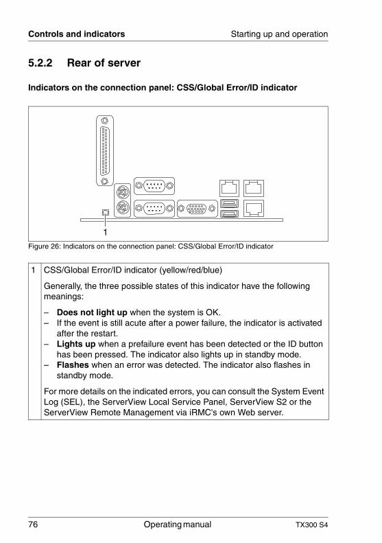
5.2.2 Rear of server
Indicators on the connection panel: CSS/Global Error/ID indicator
Figure 26: Indicators on the connection panel: CSS/Global Error/ID indicator
1 CSS/Global Error/ID indicator (yellow/red/blue)
Generally, the three possible states of this indicator have the following meanings:
– Does not light up when the system is OK.– If the event is still acute after a power failure, the indicator is activated
after the restart.– Lights up when a prefailure event has been detected or the ID button
has been pressed. The indicator also lights up in standby mode.– Flashes when an error was detected. The indicator also flashes in
standby mode.
For more details on the indicated errors, you can consult the System Event Log (SEL), the ServerView Local Service Panel, ServerView S2 or the ServerView Remote Management via iRMC's own Web server.
1
TX300 S4 Operating manual 77
Starting up and operation Controls and indicators
1 Depending on the color, the states „light up“ and „flash“ have the following meanings:
– CSS (yellow)
Lights up yellow if a prefailure event was detected for a CSS component.
Flashes yellow if an error was detected that you can fix yourself with the CSS concept (see “Customer Self Service (CSS)” on page 9).
– Global Error (red)
Lights up red if a prefailure event was detected for a non-CSS component.
Flashes red if an error was detected for a service incident.
– ID (blue)
Lights up blue when the system has been selected by pressing the ID button. To deactivate, press the button again.
– CSS/Global Error/ID (yellow/red/blue)
Lights up yellow/red/blue and/or flashes alternately yellow and/or red if several prefailure events and/or errors have been detected at the same time and/or the ID button has been pressed.
I If there is a CSS event, first check whether it was detected for a hot-plug component (see “Hard disk drive indicators” on page 75 and “Indicators on the hot-plug power supply unit” on page 79).
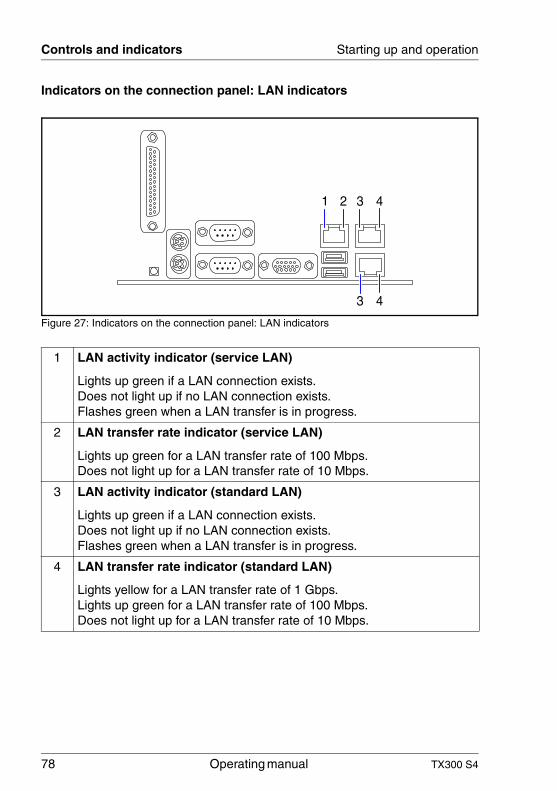
78 Operating manual TX300 S4
Controls and indicators Starting up and operation
Indicators on the connection panel: LAN indicators
Figure 27: Indicators on the connection panel: LAN indicators
1 LAN activity indicator (service LAN)
Lights up green if a LAN connection exists.Does not light up if no LAN connection exists.Flashes green when a LAN transfer is in progress.
2 LAN transfer rate indicator (service LAN)
Lights up green for a LAN transfer rate of 100 Mbps.Does not light up for a LAN transfer rate of 10 Mbps.
3 LAN activity indicator (standard LAN)
Lights up green if a LAN connection exists.Does not light up if no LAN connection exists.Flashes green when a LAN transfer is in progress.
4 LAN transfer rate indicator (standard LAN)
Lights yellow for a LAN transfer rate of 1 Gbps.Lights up green for a LAN transfer rate of 100 Mbps.Does not light up for a LAN transfer rate of 10 Mbps.
42 31
3 4
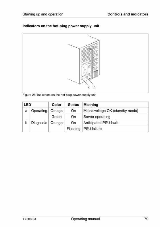
TX300 S4 Operating manual 79
Starting up and operation Controls and indicators
Indicators on the hot-plug power supply unit
Figure 28: Indicators on the hot-plug power supply unit
LED Color Status Meaning
a Operating Orange On Mains voltage OK (standby mode)
Green On Server operating
b Diagnosis Orange On Anticipated PSU fault
Flashing PSU failure
a b
80 Operating manual TX300 S4
Switching the server on and off Starting up and operation
5.3 Switching the server on and off
V CAUTION!
It nothing appears on the screen but flickering stripes after switching on the server, switch the server off immediately (see chapter “Trouble-shooting and tips” on page 89).
The On/Off button does not disconnect the server from the mains voltage. To completely disconnect it from the mains voltage, remove the power plug(s) from the socket(s).
Switching the server on
The Power-on indicator (position 8 in figure 24 on page 71) lights up orange (standby mode).
– Starting up for the first time:
Ê Press the On/Off button (item 9 in figure 24 on page 71).
Ê Insert the ServerStart DVD in the DVD drive.
Ê Follow the on-screen instructions (see also section “Configuration with ServerStart” on page 83 or section “Configuration without ServerStart” on page 84).
– System already installed:
Ê Press the On/Off button (item 9 in figure 24 on page 71).
The server is switched on, performs a system test and boots the operating system.
Switching the server off
The Power-on indicator (item 8 in figure 24 on page 71) lights up green.
Ê Shut down the operating system properly.
The server is switched off automatically and goes into standby mode. The power-on indicator lights up orange.
I If the operating system does not switch the server off automatically, press the On/Off button for at least four seconds and/or send a corresponding control signal.
TX300 S4 Operating manual 81
Starting up and operation Switching the server on and off
Other On/Off options
Besides the On/Off button, the server can be switched ON and OFF in the following ways:
– Specified switch on time / switch off time
The server is switched ON or OFF at a time specified in the ServerView program
– Ring indicator
The server is switched on by an internal or external modem.
– Wake up On LAN (WOL)
The server is switched on by a command via the LAN (Magic PacketTM).
– After power failure
The server automatically reboots following a power failure (depending of the settings in the BIOS).
82 Operating manual TX300 S4
Configuring the server Starting up and operation
5.4 Configuring the server
This section contains information about configuring the server and installing the operating system.
I Make sure that the energy saving functions are disabled in the BIOS Setup during server operation.
5.4.1 Configuring the PCI SAS controller with "Integrated Mirroring Enhanced"
The server has a PCI SAS controller with "Integrated Mirroring Enhanced" functionality. You can configure the PCI SAS controller either before or during ServerStart. Using ServerStart is recommended.
I The controller makes a separate utility available for IME configuration. Further information is included in the "Integrated RAID for SAS User’s Guide" (on the ServerBooks DVD under "Controllers").
I Descriptions of operating systems not covered in the RAID controller manual are provided in the corresponding readme files on the driver CDs.
5.4.2 Configuring the PCI SAS controller with RAID functionality
The server has a PCI SAS controller with RAID functionality. You can configure the PCI SAS controller either before or during ServerStart. Using ServerStart is recommended.
I A separate utility is available to the controller for MegaRAID configu-ration. For further information, refer to the “SAS/SATA Controller MegaRAID 1064 / 1068 / 1078 Installation Guide” on the ServerBooks DVD (select “Controllers” from the menu).
I Descriptions of operating systems not covered in the RAID controller manual are provided in the corresponding readme files on the driver CDs.
TX300 S4 Operating manual 83
Starting up and operation Configuring the server
5.4.3 Configuration with ServerStart
The ServerStart DVD supplied allows you to conveniently configure the server and install the operating system. Menu-guided configuration includes server configuration with the SCU and RAID controller configuration with ServerVie-wRAID.
The ServerStart advantages
– Automatic configuration of your server’s hardware and disk arrays.
– Installation assistance for all leading server operating systems.
– Creation of configuration files for unattended installation of several PRIMERGY servers with identical hardware configurations.
– Installation of drivers and additional software.
I The software that can be installed depends on your server’s hardware configuration. This configuration is detected automatically.
I Descriptions of operating systems not covered in the RAID controller manual are provided in the corresponding readme files on the driver CDs.
To find out how to operate ServerStart and for further information, refer to the associated manual.
If you are using ServerStart, you can skip the following section on how to configure the server and install the operating system. Continue from section “Cleaning the server” on page 85.
84 Operating manual TX300 S4
Configuring the server Starting up and operation
5.4.4 Configuration without ServerStart
Configuring the PCI SAS controller with "Integrated Mirroring Enhanced"
Configure the controller as described in section “Configuring the PCI SAS controller with "Integrated Mirroring Enhanced"” on page 82.
Configuring the PCI SAS controller with RAID functionality
Configure the controller as described in section “Configuring the PCI SAS controller with RAID functionality” on page 82.
Installing the operating system
Ê Insert the CD/DVD for the operating system you want to install.
Ê Reboot the server.
Ê Follow the instructions on screen and in the manual for the operating system.
TX300 S4 Operating manual 85
Starting up and operation Cleaning the server
5.5 Cleaning the server
V CAUTION!
Switch the server off and disconnect the power plugs from the grounded shockproof sockets.
Do not clean any interior parts yourself; leave this job to a service technician.
Do not use any cleaning agents that contain abrasives or may corrode plastic.
Ensure that no liquid enters the system. Ensure that the ventilation areas of the server and the monitor are clear.
Clean the keyboard and the mouse with a disinfecting cloth.
Wipe the server and monitor casing with a dry cloth. If particularly dirty, use a cloth that has been moistened in a mild domestic detergent and then carefully wrung out.

TX300 S4 Operating manual 87
6 Property and data protectionThe floorstand model is protected against unauthorized opening by a lock. Apart from this, the server is also fitted with an intrusion detection switch which enables the ServerView program to detect and log any removal of the left cover or housing cover and the cover for the HDD modules.
To prevent it being removed from its location, the floorstand model can be secured to a fixed object with a steel cable running through a clip on the back.
The rack model is protected against unauthorized access by a lockable rack door.
To protect your system and data internally against unauthorized access, you can use the BIOS Setup security functions.
6.1 BIOS Setup security functions
The Security menu in BIOS Setup offers various options for protecting your data from unauthorized access. By combining these options, you can also achieve optimum protection for your system.
I A detailed description of the Security menu and how to assign passwords can be found in the BIOS Setup documentation on the PRIMERGY ServerBooks DVD.
Preventing unauthorized BIOS Setup calls
You can activate this protection by entering a setup password in the Security menu. You can also suppress the Press F2 for Setup message in this menu. This message is then no longer displayed while the server's startup routine is in progress.
Preventing unauthorized system access
You can activate this protection by entering a system password in the Security menu.
Preventing unauthorized access to the boards with their own BIOS
You can activate this protection by selecting the Extended item for Setup Password Lock field in the Security menu.
88 Operating manual TX300 S4
BIOS Setup security functions Property and data protection
Preventing the system from booting from the floppy disk drive
You can activate this protection by selecting the item Diskette Lock for the System Load field in the Security menu.
Preventing unauthorized writings of floppy disks
To activate this protection, select the value Disabled for the Diskette Write field in the Security menu.
Protecting BIOS from being overwritten
To activate this protection, select the value Disabled for the Flash Write field in the Security menu.
Protecting the server from being switched on by an external device
To activate this protection, select the value Disabled for the Remote Power On field in the Security menu.
Protecting the server from being switched off by a program
To activate this protection, select the value Disabled for the Soft Power Off field in the Security menu.
TX300 S4 Operating manual 89
7 Troubleshooting and tipsV CAUTION!
Follow the safety instructions in the “Safety notes and other important information” manual and in chapter “Important information” on page 25.
If a fault occurs, attempt to resolve it using the measures described:
– in this chapter,– in the documentation for the connected devices,– in the help systems of the software used.
If you fail to correct the problem, proceed as follows:
Ê Make a list of the steps performed and the circumstances that led to the fault. Also make a list of any error messages that were displayed.
Ê Switch off the server.
Ê Contact our customer service team.
7.1 Power-on indicator remains unlit
The power-on indicator remains dark after you switch on your device.
Power cable incorrectly connected
Ê Make sure that the power cable(s) is/are correctly connected to the server and the grounded socket(s).
Power supply overloaded
Ê Disconnect the server power plug(s) from the power socket(s).
Ê Wait a few seconds before you plug it/them into the grounded socket(s) again.
Ê Switch on your server.
90 Operating manual TX300 S4
Server switches itself off Troubleshooting and tips
7.2 Server switches itself off
Server Management has detected an error
Ê Check the error list or the ErrorLog file in the ServerView program, and attempt to eliminate the error.
7.3 Screen remains blank
Monitor is switched off
Ê Switch on your monitor.
Screen has gone blank
Ê Press any key on the keyboard.
or
Ê Deactivate screen saver. Enter the appropriate password.
Brightness control is set to dark
Ê Set the brightness control on the monitor to light. For detailed information, refer to the operating manual supplied with your monitor.
Power cable or monitor cable not connected
Ê Switch off the monitor and the server.
Ê Check whether the power cable is properly connected to the monitor and to the grounded socket.
Ê Check whether the monitor cable is properly connected to the server and monitor (if it is plugged in with a connector). If a separate graphics card is installed in the server, then the monitor cable must be connected to the graphics card.
Ê Switch on the monitor and the server.
TX300 S4 Operating manual 91
Troubleshooting and tips Flickering stripes on monitor screen
7.4 Flickering stripes on monitor screen
V CAUTION!
Switch off the server immediately. Risk of damaging the server.
Monitor does not support the set horizontal frequency
Ê Find out which horizontal frequency your monitor screen supports. You will find the horizontal frequency (also known as line frequency or horizontal deflection frequency) in the documentation for your monitor.
Ê Refer to the documentation for your operating system or the software for the screen controller for details of how to set the correct horizontal frequency for your monitor, and follow the procedure accordingly.
7.5 No screen display or display drifts
The wrong horizontal frequency or resolution has been selected for the monitor or for the application program.
Ê Find out which horizontal frequency your monitor screen supports. You will find the horizontal frequency (also known as line frequency or horizontal deflection frequency) in the documentation for your monitor.
Ê Refer to the documentation for your operating system or the software for the screen controller for details of how to set the correct horizontal frequency for your monitor, and follow the procedure accordingly.
92 Operating manual TX300 S4
No mouse pointer displayed on screen Troubleshooting and tips
7.6 No mouse pointer displayed on screen
Mouse driver not loaded
Ê Check whether the mouse driver is properly installed and is activated when the application program is started. Detailed information can be found in the user manuals for the mouse, the operating system and the application program.
Mouse controller disabled
The mouse controller on the system board must be enabled if you are using the mouse supplied.
Ê Check in the BIOS Setup that the mouse controller is Enabled.
7.7 Unable to read from / write to floppy disk
Ê Check whether the write protection for the floppy disk is activated.
Ê Check the entry for the floppy disk drive in the BIOS Setup.
Ê Check in the BIOS Setup whether the floppy disk drive controller and write permission are enabled (see technical manual for system board on the PRIMERGY ServerBooks DVD).
TX300 S4 Operating manual 93
Troubleshooting and tips Incorrect date and time
7.8 Incorrect date and time
Ê Set the date and time in the operating system or in the BIOS Setup under the Main menu, using System Date and System Time respectively.
I Note that the operating system may affect the system time. For example, the operating system time may deviate from the system time under Linux, and would overwrite the system time in the default setting on shutdown.
If the date and time are still wrong after the server has been switched off and back on again, replace the lithium battery (for a description refer to the Technical Manual for the D2529 system board) or contact our customer service team.
7.9 Hard disk drive error messages at system boot
Various hard disk drive error messages may occur when the system is rebooted. These error messages are caused by modifications in the selected RAID config-uration.
RAID controller configuration incorrect
Ê Check and correct the settings for the drives using the RAID controller configuration program.
Further information is provided in the manual for the RAID controller.
94 Operating manual TX300 S4
Added drive reported as defective Troubleshooting and tips
7.10 Added drive reported as defective
RAID controller is not configured for this drive
The drive was probably installed when the system was switched off.
Ê Reconfigure the RAID controller for the drive using the corresponding utility. Information is provided in the documentation for the RAID controller.
or
Ê Remove and reinstall the drive while the system is switched ON.
If the hard disk drive continues to be shown as defective, then replace it (see “Hot-plug hard disk drives” on page 97).
7.11 Error message on screen
The meaning of the error message is explained in the manual for the BIOS Setup and in the documentation for the relevant components and programs on the PRIMERGY ServerBooks DVD.
TX300 S4 Operating manual 95
8 CSS componentsThis chapter describes how to handle CSS components and how to identify defective CSS components and replace them yourself.
I Further information on the CSS concept is provided in the “Customer Self Service (CSS)” manual on the ServerBooks DVD.
V CAUTION!
Follow the safety instructions in the chapter “Important information” on page 25.
In the PRIMERGY TX300 S4 server, the following components are considered to be CSS components:
– Hot-plug components
– Hot-plug power supply units– Hot plug hard disk drives– Hot-plug CPU / system fans (depending on version)
You can expand or replace the hot-plug components during operation.
– Non-hot-plug components
– Memory modules– System fans (depending on version)– Expansion cards
These components can be changed by you in the event of an error. Expan-sions and upgrades may only be carried out by authorized specialist personnel. These operations are described in the "Options Guide".
8.1 Hot-plug components
This section describes how to handle the hot-plug components and/or how to modify your server hardware (e.g. adding/replacing hot-plug power supply units or hot-plug HDD modules).
The hot-plug procedure increases the availability of system operation and guarantees a high degree of data integrity and failsafe performance.
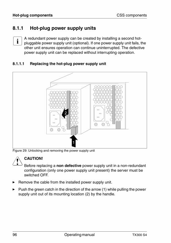
96 Operating manual TX300 S4
Hot-plug components CSS components
8.1.1 Hot-plug power supply units
I A redundant power supply can be created by installing a second hot-pluggable power supply unit (optional). If one power supply unit fails, the other unit ensures operation can continue uninterrupted. The defective power supply unit can be replaced without interrupting operation.
8.1.1.1 Replacing the hot-plug power supply unit
Figure 29: Unlocking and removing the power supply unit
V CAUTION!
Before replacing a non defective power supply unit in a non-redundant configuration (only one power supply unit present) the server must be switched OFF.
Ê Remove the cable from the installed power supply unit.
Ê Push the green catch in the direction of the arrow (1) while pulling the power supply unit out of its mounting location (2) by the handle.
TX300 S4 Operating manual 97
CSS components Hot-plug components
Ê Slide the new power supply unit into the empty slot until it clicks into place.
I Make sure that the power supply unit engages correctly in the slot and is locked in position.
This is the only way to prevent the power supply unit from sliding out of its mountings and being damaged during transportation.
Ê Connect the newly installed power supply unit.
8.1.2 Hot-plug hard disk drives
In the PRIMERGY TX300 S4 server you can use up to eight 3.5-inch SAS/SATA hard disk drives or up to twenty 2.5-inch SAS hard disk drives.
The hard disk drives which can be ordered for the PRIMERGY TX300 S4 are supplied already mounted in an installation frame so that defective hard disk drives can be replaced and new drives can be added during operation. The hard disk drive and installation frame together make up the HDD module.
V CAUTION!
● The hard disk drive may not be removed from the installation frame by anyone except a service technician.
● The HDD modules (drives) must all be marked clearly so that they can be put back in their original places after an upgrade. If this is not done, existing data can be lost.
● The hot-plug function is only possible in conjunction with a corre-sponding RAID configuration.
Further information about the RAID configuration or RAID level can be found in the RAID controller documentation.
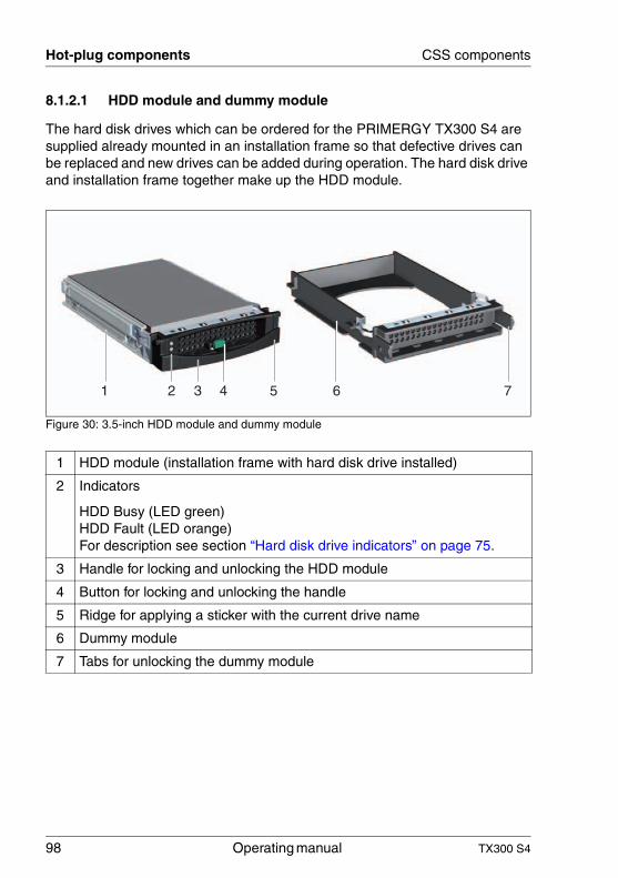
98 Operating manual TX300 S4
Hot-plug components CSS components
8.1.2.1 HDD module and dummy module
The hard disk drives which can be ordered for the PRIMERGY TX300 S4 are supplied already mounted in an installation frame so that defective drives can be replaced and new drives can be added during operation. The hard disk drive and installation frame together make up the HDD module.
Figure 30: 3.5-inch HDD module and dummy module
1 HDD module (installation frame with hard disk drive installed)
2 Indicators
HDD Busy (LED green)HDD Fault (LED orange)For description see section “Hard disk drive indicators” on page 75.
3 Handle for locking and unlocking the HDD module
4 Button for locking and unlocking the handle
5 Ridge for applying a sticker with the current drive name
6 Dummy module
7 Tabs for unlocking the dummy module
1 6 75
4
32 4
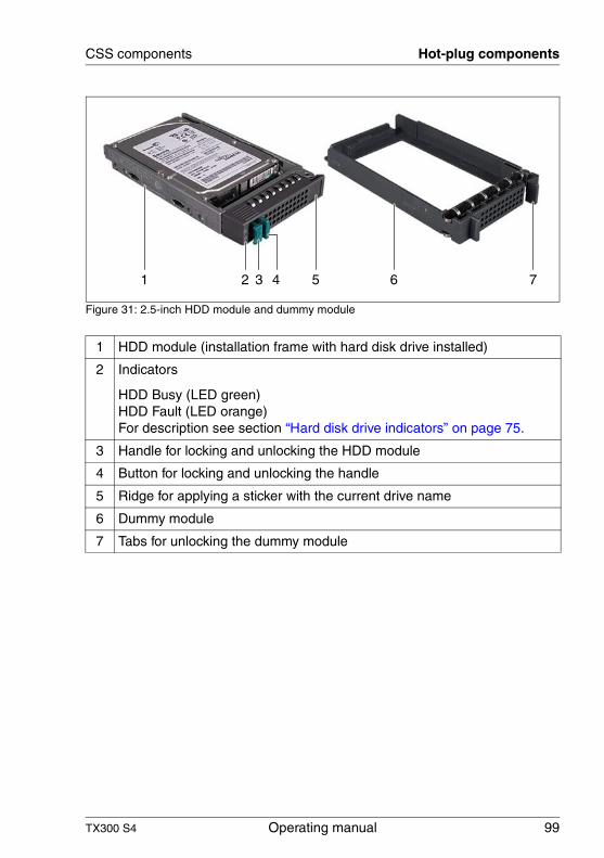
TX300 S4 Operating manual 99
CSS components Hot-plug components
Figure 31: 2.5-inch HDD module and dummy module
1 HDD module (installation frame with hard disk drive installed)
2 Indicators
HDD Busy (LED green)HDD Fault (LED orange)For description see section “Hard disk drive indicators” on page 75.
3 Handle for locking and unlocking the HDD module
4 Button for locking and unlocking the handle
5 Ridge for applying a sticker with the current drive name
6 Dummy module
7 Tabs for unlocking the dummy module
1 2 3 4 5 6 7
100 Operating manual TX300 S4
Hot-plug components CSS components
8.1.2.2 Handling hard disk drives and HDD modules
Hard disk drives incorporated in the HDD modules are highly sensitive electro-magnetic devices and must be handled with great care. Incorrect handling can cause partial or total failure of the hard disk drives. These failures can result in data errors and to a loss of data or to total corruption of the hard disk drive.
Observe the following rules to prevent such problems occurring:
● Only store and transport HDD modules within the limits stipulated in the specification.
● When transporting HDD modules (even over short distances), always use the original packaging (ESD label).
● Never expose HDD modules to a temperature shock. Avoid the formation of condensation inside and on the outside of the hard disk drive.
V CAUTION!
The HDD module must be acclimatized in its operating environment for an acclimatization time before it is started up for the first time.
● Always set the HDD module down carefully, with the large surface facing downwards to prevent it from tipping over.
Temperature difference (°C)(operating environment/
outside)
Minimum acclimatization time (hours)
5 3
10 5
15 7
20 8
25 9
30 10
Table 2: Acclimatization times for HDD modules
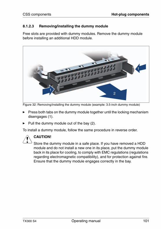
TX300 S4 Operating manual 101
CSS components Hot-plug components
8.1.2.3 Removing/installing the dummy module
Free slots are provided with dummy modules. Remove the dummy module before installing an additional HDD module.
Figure 32: Removing/installing the dummy module (example: 3.5-inch dummy module)
Ê Press both tabs on the dummy module together until the locking mechanism disengages (1).
Ê Pull the dummy module out of the bay (2).
To install a dummy module, follow the same procedure in reverse order.
V CAUTION!
Store the dummy module in a safe place. If you have removed a HDD module and do not install a new one in its place, put the dummy module back in its place for cooling, to comply with EMC regulations (regulations regarding electromagnetic compatibility), and for protection against fire. Ensure that the dummy module engages correctly in the bay.
1
1
2
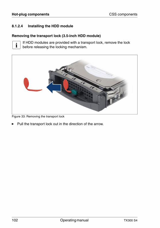
102 Operating manual TX300 S4
Hot-plug components CSS components
8.1.2.4 Installing the HDD module
Removing the transport lock (3.5-inch HDD module)
I If HDD modules are provided with a transport lock, remove the lock before releasing the locking mechanism.
Figure 33: Removing the transport lock
Ê Pull the transport lock out in the direction of the arrow.
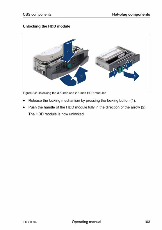
TX300 S4 Operating manual 103
CSS components Hot-plug components
Unlocking the HDD module
Figure 34: Unlocking the 3.5-inch and 2.5-inch HDD modules
Ê Release the locking mechanism by pressing the locking button (1).
Ê Push the handle of the HDD module fully in the direction of the arrow (2).
The HDD module is now unlocked.
2
1
1
21
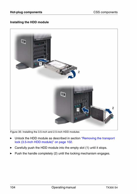
104 Operating manual TX300 S4
Hot-plug components CSS components
Installing the HDD module
Figure 35: Installing the 3.5-inch and 2.5-inch HDD modules
Ê Unlock the HDD module as described in section “Removing the transport lock (3.5-inch HDD module)” on page 102.
Ê Carefully push the HDD module into the empty slot (1) until it stops.
Ê Push the handle completely (2) until the locking mechanism engages.
21
1
2
TX300 S4 Operating manual 105
CSS components Hot-plug components
8.1.2.5 Removing the HDD module
V CAUTION!
● Only remove a HDD module during operation if the drive is not currently being accessed. Observe the control LEDs for the corre-sponding HDD modules (see “Hard disk drive indicators” on page 75).
● Under no circumstances should you remove a HDD module while the system is in operation if you are not sure that the hard disk drive is operated by a RAID controller and belongs to a disk array that is operating in RAID level 1, 10, 5, 50, 6 or 60.
A HDD module can only be replaced during operation in conjunction with a corresponding RAID configuration.
● All HDD modules (drives) must be uniquely identified so that they can be reinstalled in their original mounting locations later. If this is not done, existing data can be lost.
If you want to remove a HDD module during operation, proceed as follows:
Ê If you want to remove a HDD module that is not defective, the drive must be first set to "Offline" via the software (RAID controller configuration software).
Ê Unlock the HDD module as described in section “Unlocking the HDD module” on page 103.
Ê Pull the HDD module out a few centimeters.
Ê Wait for at least 60 seconds.
I This period is necessary for the RAID controller to recognize that a HDD module has been removed and for the hard disk drive to come to a stop.
Ê Pull the HDD module out completely.
106 Operating manual TX300 S4
Hot-plug components CSS components
Ê Install the new HDD module, as described in “Installing the HDD module” on page 102.
V CAUTION!
If you have removed a HDD module and do not install a new one in its place, put the dummy module back in its place for cooling, to comply with EMC regulations (regulations regarding electromagnetic compatibility), and for protection against fire. Ensure that the dummy module engages correctly in the bay.
TX300 S4 Operating manual 107
CSS components Hot-plug components
8.1.3 Replacing hot-plug CPU/system fans
Depending on the version, the server is equipped with a CPU fan unit (one hot-plug CPU fan per CPU) and four system fans.
V CAUTION!
The actions described in this section may only be performed by personnel with the appropriate technical training. (The device can be seriously damaged if it is opened without authorization or if repairs are attempted by untrained personnel.)
Please observe the safety information in chapter “Important information” on page 25.
In order to replace a defective fan, the left side cover (floorstand model) or the housing cover (rack model) must be removed as the fans are not directly accessible (see section “Opening/closing the housing” on page 121).
The four system fans work in redundant mode, which means that a defective fan can be replaced at the next scheduled service. A defective CPU fan must be replaced immediately.
The failure of a fan is indicated by the CSS indicator on the front and rear of the server (flashes orange).
The fan that has failed is indicated on the fan itself. The indicators are not visible unless the housing is open.
Ê Remove the left side cover (floorstand model) or the housing cover (rack model) (see section “Opening/closing the housing” on page 121).
V CAUTION!
The side/housing cover must be reinstalled as soon as possible due to cooling, to comply with applicable EMC regulations (regulations on electromagnetic compatibility) and to protect against fire. The housing must not be left uncovered for more than 60 minutes.
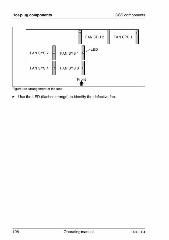
108 Operating manual TX300 S4
Hot-plug components CSS components
Figure 36: Arrangement of the fans
Ê Use the LED (flashes orange) to identify the defective fan.
FAN SYS 2
FAN SYS 3FAN SYS 4
FAN SYS 1
Front
LED
FAN CPU 1FAN CPU 2
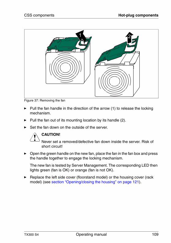
TX300 S4 Operating manual 109
CSS components Hot-plug components
Figure 37: Removing the fan
Ê Pull the fan handle in the direction of the arrow (1) to release the locking mechanism.
Ê Pull the fan out of its mounting location by its handle (2).
Ê Set the fan down on the outside of the server.
V CAUTION!
Never set a removed/defective fan down inside the server. Risk of short circuit!
Ê Open the green handle on the new fan, place the fan in the fan box and press the handle together to engage the locking mechanism.
The new fan is tested by Server Management. The corresponding LED then lights green (fan is OK) or orange (fan is not OK).
Ê Replace the left side cover (floorstand model) or the housing cover (rack model) (see section “Opening/closing the housing” on page 121).
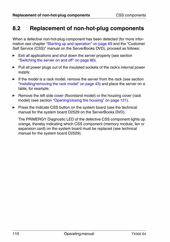
110 Operating manual TX300 S4
Replacement of non-hot-plug components CSS components
8.2 Replacement of non-hot-plug components
When a defective non-hot-plug component has been detected (for more infor-mation see chapter “Starting up and operation” on page 69 and the "Customer Self Service (CSS)" manual on the ServerBooks DVD), proceed as follows:
Ê Exit all applications and shut down the server properly (see section “Switching the server on and off” on page 80).
Ê Pull all power plugs out of the insulated sockets of the rack's internal power supply.
Ê If the model is a rack model, remove the server from the rack (see section “Installing/removing the rack model” on page 43) and place the server on a table, for example.
Ê Remove the left side cover (floorstand model) or the housing cover (rack model) (see section “Opening/closing the housing” on page 121).
Ê Press the Indicate CSS button on the system board (see the technical manual for the system board D2529 on the ServerBooks DVD).
The PRIMERGY Diagnostic LED of the defective CSS component lights up orange, thereby indicating which CSS component (memory module, fan or expansion card) on the system board must be replaced (see technical manual for the system board D2529).
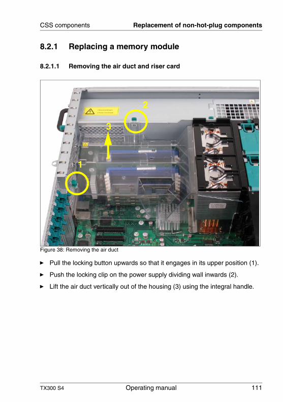
TX300 S4 Operating manual 111
CSS components Replacement of non-hot-plug components
8.2.1 Replacing a memory module
8.2.1.1 Removing the air duct and riser card
Figure 38: Removing the air duct
Ê Pull the locking button upwards so that it engages in its upper position (1).
Ê Push the locking clip on the power supply dividing wall inwards (2).
Ê Lift the air duct vertically out of the housing (3) using the integral handle.
1
2
3
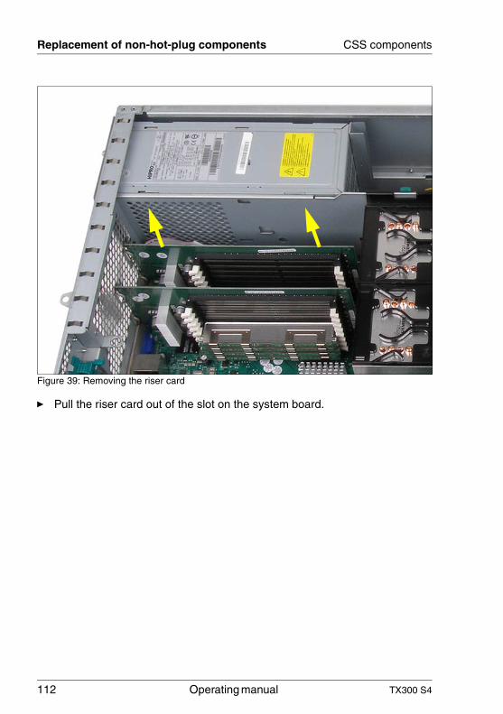
112 Operating manual TX300 S4
Replacement of non-hot-plug components CSS components
Figure 39: Removing the riser card
Ê Pull the riser card out of the slot on the system board.
TX300 S4 Operating manual 113
CSS components Replacement of non-hot-plug components
8.2.1.2 Removing a defective memory module
Figure 40: Removing a memory module
Ê Press the holders on either side of the mounting location concerned outward (1).
Ê If the slot was equipped: pull the memory module out of the slot (2).
1
2 1
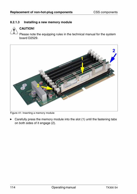
114 Operating manual TX300 S4
Replacement of non-hot-plug components CSS components
8.2.1.3 Installing a new memory module
V CAUTION!
Please note the equipping rules in the technical manual for the system board D2529.
Figure 41: Inserting a memory module
Ê Carefully press the memory module into the slot (1) until the fastening tabs on both sides of it engage (2).
2
1
2
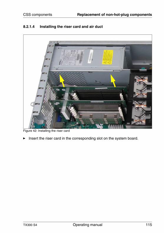
TX300 S4 Operating manual 115
CSS components Replacement of non-hot-plug components
8.2.1.4 Installing the riser card and air duct
Figure 42: Installing the riser card
Ê Insert the riser card in the corresponding slot on the system board.
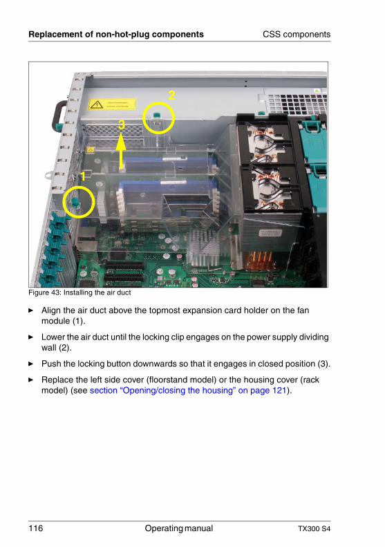
116 Operating manual TX300 S4
Replacement of non-hot-plug components CSS components
Figure 43: Installing the air duct
Ê Align the air duct above the topmost expansion card holder on the fan module (1).
Ê Lower the air duct until the locking clip engages on the power supply dividing wall (2).
Ê Push the locking button downwards so that it engages in closed position (3).
Ê Replace the left side cover (floorstand model) or the housing cover (rack model) (see section “Opening/closing the housing” on page 121).
1
2
3
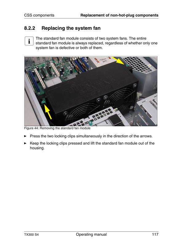
TX300 S4 Operating manual 117
CSS components Replacement of non-hot-plug components
8.2.2 Replacing the system fan
I The standard fan module consists of two system fans. The entire standard fan module is always replaced, regardless of whether only one system fan is defective or both of them.
Figure 44: Removing the standard fan module
Ê Press the two locking clips simultaneously in the direction of the arrows.
Ê Keep the locking clips pressed and lift the standard fan module out of the housing.
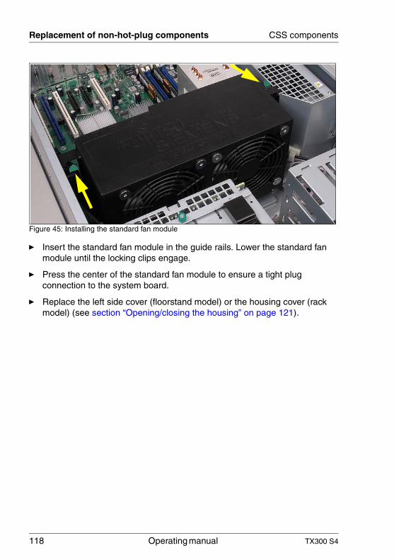
118 Operating manual TX300 S4
Replacement of non-hot-plug components CSS components
Figure 45: Installing the standard fan module
Ê Insert the standard fan module in the guide rails. Lower the standard fan module until the locking clips engage.
Ê Press the center of the standard fan module to ensure a tight plug connection to the system board.
Ê Replace the left side cover (floorstand model) or the housing cover (rack model) (see section “Opening/closing the housing” on page 121).
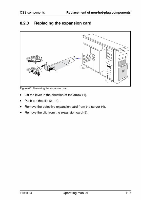
TX300 S4 Operating manual 119
CSS components Replacement of non-hot-plug components
8.2.3 Replacing the expansion card
Figure 46: Removing the expansion card
Ê Lift the lever in the direction of the arrow (1).
Ê Push out the clip (2 + 3).
Ê Remove the defective expansion card from the server (4).
Ê Remove the clip from the expansion card (5).
4
51
23
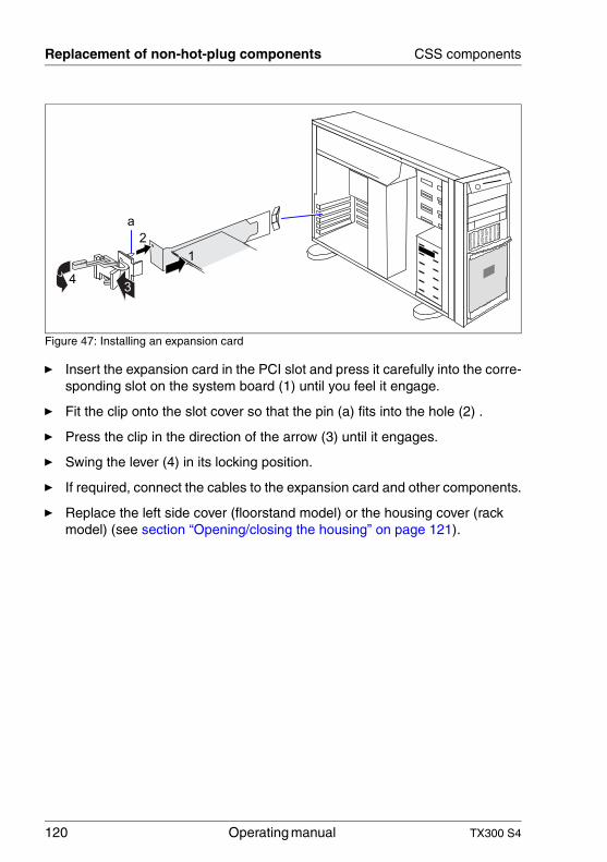
120 Operating manual TX300 S4
Replacement of non-hot-plug components CSS components
Figure 47: Installing an expansion card
Ê Insert the expansion card in the PCI slot and press it carefully into the corre-sponding slot on the system board (1) until you feel it engage.
Ê Fit the clip onto the slot cover so that the pin (a) fits into the hole (2) .
Ê Press the clip in the direction of the arrow (3) until it engages.
Ê Swing the lever (4) in its locking position.
Ê If required, connect the cables to the expansion card and other components.
Ê Replace the left side cover (floorstand model) or the housing cover (rack model) (see section “Opening/closing the housing” on page 121).
1
2
34
a
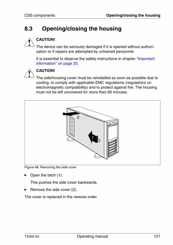
TX300 S4 Operating manual 121
CSS components Opening/closing the housing
8.3 Opening/closing the housing
V CAUTION!
The device can be seriously damaged if it is opened without authori-zation or if repairs are attempted by untrained personnel.
It is essential to observe the safety instructions in chapter “Important information” on page 25.
V CAUTION!
The side/housing cover must be reinstalled as soon as possible due to cooling, to comply with applicable EMC regulations (regulations on electromagnetic compatibility) and to protect against fire. The housing must not be left uncovered for more than 60 minutes.
Figure 48: Removing the side cover
Ê Open the latch (1).
This pushes the side cover backwards.
Ê Remove the side cover (2).
The cover is replaced in the reverse order.
1
2

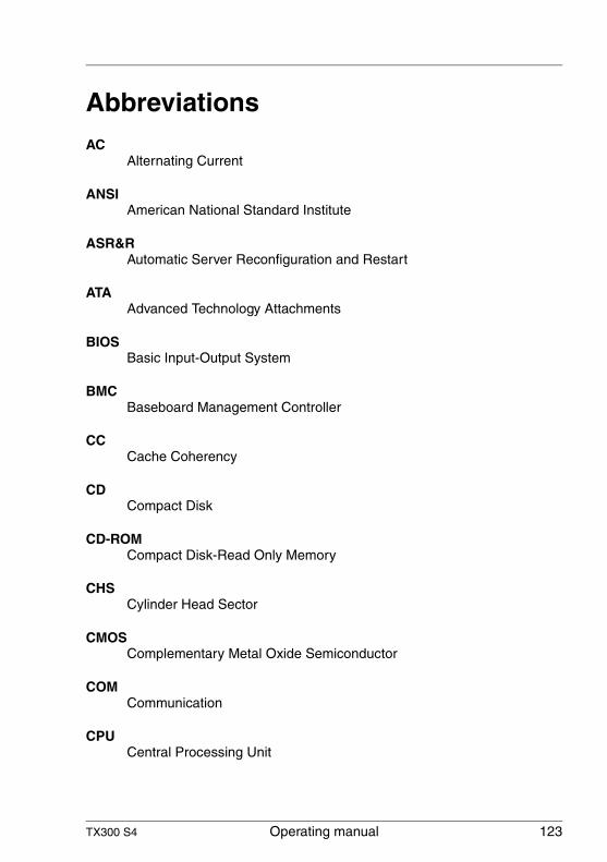
TX300 S4 Operating manual 123
AbbreviationsAC
Alternating Current
ANSIAmerican National Standard Institute
ASR&RAutomatic Server Reconfiguration and Restart
ATAAdvanced Technology Attachments
BIOSBasic Input-Output System
BMCBaseboard Management Controller
CCCache Coherency
CDCompact Disk
CD-ROMCompact Disk-Read Only Memory
CHSCylinder Head Sector
CMOSComplementary Metal Oxide Semiconductor
COMCommunication
CPUCentral Processing Unit
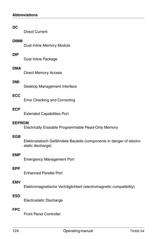
124 Operating manual TX300 S4
Abbreviations
DCDirect Current
DIMMDual Inline Memory Module
DIPDual Inline Package
DMADirect Memory Access
DMIDesktop Management Interface
ECCError Checking and Correcting
ECPExtended Capabilities Port
EEPROMElectrically Erasable Programmable Read-Only Memory
EGBElektrostatisch Gefährdete Bauteile (components in danger of electro-static discharge)
EMPEmergency Management Port
EPPEnhanced Parallel Port
EMVElektromagnetische Verträglichkeit (electromagnetic compatibility)
ESDElectrostatic Discharge
FPCFront Panel Controller
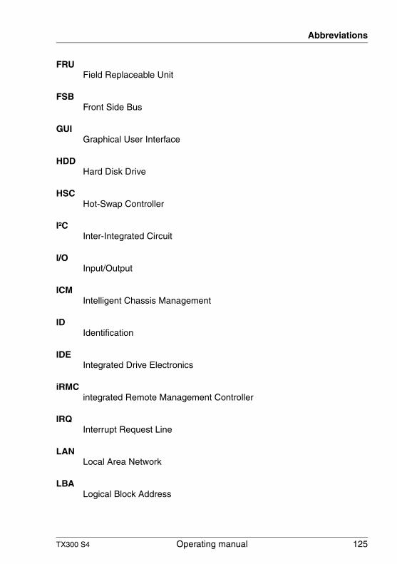
TX300 S4 Operating manual 125
Abbreviations
FRUField Replaceable Unit
FSBFront Side Bus
GUIGraphical User Interface
HDDHard Disk Drive
HSCHot-Swap Controller
I²CInter-Integrated Circuit
I/OInput/Output
ICMIntelligent Chassis Management
IDIdentification
IDEIntegrated Drive Electronics
iRMCintegrated Remote Management Controller
IRQInterrupt Request Line
LANLocal Area Network
LBALogical Block Address
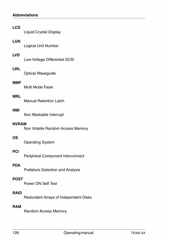
126 Operating manual TX300 S4
Abbreviations
LCDLiquid Crystal Display
LUNLogical Unit Number
LVDLow-Voltage Differential SCSI
LWLOptical Waveguide
MMFMulti Mode Faser
MRLManual Retention Latch
NMINon Maskable Interrupt
NVRAMNon Volatile Random Access Memory
OSOperating System
PCIPeripheral Component Interconnect
PDAPrefailure Detection and Analysis
POSTPower ON Self Test
RAIDRedundant Arrays of Independent Disks
RAMRandom Access Memory
TX300 S4 Operating manual 127
Abbreviations
ROMRead-Only Memory
RSBRemote Service Board
RTCReal Time Clock
RTDSRemote Test and Diagnosis System
SAF-TESCSI Accessed Fault-Tolerance Enclosures
SBESingle Bit Error
SASSerial Attached SCSI
SATASerial ATA
SCASingle Connector Attachment
SCSISmall Computer System Interface
SDDCSingle Device Data Correction
SDRSensor Data Record
SDRAMSynchronous Dynamic Random Access Memory
SELSystem Event Log
128 Operating manual TX300 S4
Abbreviations
SMISystem Management Interrupt
SSUSystem Setup Utility
SVGASuper Video Graphics Adapter
USBUniversal Serial Bus
VGAVideo Graphics Adapter
ZCRZero Channel RAID
TX300 S4 Operating manual 129
Index
3rd party rackinstalling in 57requirements 45
Aaccessible drives
CD burner 12CD-ROM 12diskette drive 12DVD-ROM 12magnetic tape drive 12
acclimatization time 39, 100Advanced Video Redirection 15ambient conditions 21articulated cable guide 49, 50, 53
attaching 53fitting 53
ASR&R 14availability 14AVR 15
BBIOS
security functions 87update 17
Ccable tie 54, 56cables
connecting 68disconnecting 68
cage nut 48, 51CD/DVD drive activity indicator 71,
74CE marking 20, 32Class A Compliance Statement 33Classic Rack
installing server 51requirements 44
cleaningkeyboard 85monitor 85mouse 85server 85
closing, housing 121components
hardware 7software 7
configurationserver 82
connecting cables 68consumables 36control panel 71controls 71cooling, fans 13correcting faults 89CPU, fans 13CSS indicator 71, 73
Ddata manipulation 7data protection 87data security 14DataCenter Rack, requirements 44date, incorrect 93delivery note 23, 40devices, connecting to server 64disconnecting cables 68disposal, devices 37drive
defective 94indicators 74
dummy module, HDD module 101, 106
EECC 14EDC 14electrical data 19electromagnetic compatibility 20, 32
130 Operating manual TX300 S4
Index
electrostatic-sensitive devices (ESD) 31
EMC directive 20EMC regulations 101, 106environment class 21environmental protection 36error
drifting display on monitor 91drive defective 94floppy disk cannot be read or
written 92incorrect date 93incorrect time 93no display on monitor 91no mouse pointer 92power-on indicator does not
light 89screen remains blank 90screen shows flickering
stripes 91server switches itself off 90
Error Correcting Code 14Error Detection Code 14error message on screen 94ESD (electrostatic-sensitive
devices) 31
Ffan
installing/removing 107replacing 107
fansCPU 13power supply unit 13system 13
faultdrifting display on monitor 91drive defective 94incorrect date 93incorrect time 93no display on monitor 91screen remains blank 90screen shows flickering
stripes 91FCC statement 33features 9fiber channel fiber optic cable, protec-
tive hose 55Flash EPROM 17floppy disk
cannot be read or written 92floppy disk drive activity indicator 71,
74
GGlobal Error indicator 71, 73graphics card 65
Hhard disk activity indicator 71, 72hard disk drive 11
handling 100installation frame 97online replacement 105
hard disk drive indicators 75HDD module 97
acclimatization time 39, 100installation frame 102installing 102
height units 48, 51hot-plug fan 107hot-plug power supply unit 65, 96housing
closing 121opening 121
TX300 S4 Operating manual 131
Index
IID button 71, 72ID indicator 71, 74IME (Integrated Mirroring
Enhanced) 82indicators
CD/DVD drive activity 71, 74CSS 71, 73floppy disk drive activity 71, 74Global Error 71, 73hard disk activity 71, 72hard disk drive 75ID 71, 74LAN activity 78LAN transfer rate 78on power supply unit 79on server 71operation 71system errors 73
information material, additional 9installing in
3rd party rack 57Classic Rack 51PRIMECENTER rack 48
installing in the rack, notes 35installing the operating system 84installing, server 43Integrated Mirroring Enhanced
(IME) 82integrated Remote Management
Controller 15iRMC S2 15
Llabels 37LAN activity indicator 78LAN transfer rate indicator 78laser information 30light emitting diode (LED) 30lithium battery 29Low Voltage Directive 20, 32
Mmains voltage, connecting server 65meaning of the symbols 19Memory Mirroring 14memory scrubbing 14monitor
display drifts 91no display 91
mouse, no mouse pointer on screen 92
NNMI button 71, 72noise level 22notational conventions 19
OOn/Off button 71, 72online replacement 105opening, housing 121operation 69overload 16
Ppackaging 36, 40PCI SAS controller, configuring 84PCI slot 10PDA 14, 16ports 64
USB 71power supply unit
cable clamp 66fans 13hot plug 65indicators 79redundant 65replacing 96
power supply, redundant 65power-on indicator 71, 72
does not light 89PRIMECENTER Rack
requirements 44PRIMECENTER rack
installing server 48
132 Operating manual TX300 S4
Index
PRIMERGY Diagnostic LED 17property protection 87protective hose, fiber channel fiber op-
tic cable 55
Rrack installation kit 51rack, requirements 43RAID configuration 82RAID controller is not configured for
this drive 94RAID level 14rating plate 40recycling devices 37redundancy, fans 13regulations and standards 20Remote Storage 15removing, server 43replacing
fan 107power supply unit 96
requirements3rd party rack 45Classic Rack 44DataCenter Rack 44PRIMECENTER Rack 44
reset button 71, 72return of devices 37routing
cables 49, 50
Ssafety instructions 25safety standards 20SAS controller
IME configuration 82RAID configuration 82
saving energy 36screen
error message 94flickering 91remains blank 90shows flickering stripes 91
SDDC (Single Device Data Correction) 14
security function 7security functions
setup password 87system password 87unauthorized access 87
serverambient conditions 21closing the housing 121configuration 16configuring 82connecting external devices 64connecting mains voltage 65control panel 71correcting faults 89data protection 87dimensions 21electrical data 19fitting in rack 43height units 48, 51hot-plug power supply unit 96hot-plug system fan 107ID button 71indicators 71installing 43NMI button 71noise level 22opening the housing 121operation 69ports 64power-on indicator 72property protection 87rack installation kit 51removing 43reset button 72routing cables 49, 50service 17setting up 40startup 69switches itself off (error) 90switching off 80switching on 80technical data 19
TX300 S4 Operating manual 133
Index
transport 34troubleshooting 89unpacking 40
server management 16ServerStart 16, 83ServerView 16
supported functions 16ServerView Local Service
Display 12ServerView Remote
Management 17, 18service
PRIMERGY Diagnostic LED 17server 17touch point 17
service LAN port 15setting up, server 40setup password 87Single Device Data Correction
(SDDC) 14spring nut 48startup
server 69support bracket 48switch off time, defining 81switch on time, defining 81switching off, server 80switching on, server 80system board 10
PRIMERGY Diagnostic LED 17system fans 13system fans, redundant 13system password 87
Ttarget group 7technical data 19telescopic rail 49, 50, 52time, incorrect 93tips 89touch point, service 17transport damage 23, 40transporting the server 34troubleshooting 89troubleshooting, server 89
Uunauthorized access 87unpacking, server 40USB port 71using the cable clamp 66

Information on this document On April 1, 2009, Fujitsu became the sole owner of Fujitsu Siemens Compu-ters. This new subsidiary of Fujitsu has been renamed Fujitsu Technology So-lutions.
This document from the document archive refers to a product version which was released a considerable time ago or which is no longer marketed.
Please note that all company references and copyrights in this document have been legally transferred to Fujitsu Technology Solutions.
Contact and support addresses will now be offered by Fujitsu Technology So-lutions and have the format …@ts.fujitsu.com.
The Internet pages of Fujitsu Technology Solutions are available at http://ts.fujitsu.com/... and the user documentation at http://manuals.ts.fujitsu.com.
Copyright Fujitsu Technology Solutions, 2009
Hinweise zum vorliegenden Dokument Zum 1. April 2009 ist Fujitsu Siemens Computers in den alleinigen Besitz von Fujitsu übergegangen. Diese neue Tochtergesellschaft von Fujitsu trägt seit-dem den Namen Fujitsu Technology Solutions.
Das vorliegende Dokument aus dem Dokumentenarchiv bezieht sich auf eine bereits vor längerer Zeit freigegebene oder nicht mehr im Vertrieb befindliche Produktversion.
Bitte beachten Sie, dass alle Firmenbezüge und Copyrights im vorliegenden Dokument rechtlich auf Fujitsu Technology Solutions übergegangen sind.
Kontakt- und Supportadressen werden nun von Fujitsu Technology Solutions angeboten und haben die Form …@ts.fujitsu.com.
Die Internetseiten von Fujitsu Technology Solutions finden Sie unter http://de.ts.fujitsu.com/..., und unter http://manuals.ts.fujitsu.com finden Sie die Benutzerdokumentation.
Copyright Fujitsu Technology Solutions, 2009


![PRIMERGY BX620 S4 (Xeon® X5355 / E5310 / 5160 …...2007/05/14 · PRIMERGY BX620 S4 (Xeon® X5355 / E5310 / 5160 / 5130 / 5110 搭載タイプ) [A-1] PRIMERGY BX620 S4 サーバブレード](https://img.pdfslide.net/doc/110x75/5f22fbfe212d1d184b19d6c3/primergy-bx620-s4-xeon-x5355-e5310-5160-20070514-primergy-bx620.jpg)