Embed Size (px)
Citation preview

Mylos KNXProgrammable Thermostat2CSYK1201C/S
Product manual

2 Sommario | MYLOS® Building Automation
MYLOS® Building Automation Sommario
Sommario
1 General............................................................................................... 41.1 Functions overview ........................................................................................ 4
2 Technical features ............................................................................. 52.1 Technical data ................................................................................................ 52.2 Connection diagram ....................................................................................... 72.3 Dimensional drawing ...................................................................................... 72.4 Assembly and installation ............................................................................. 8
3 Main configurations ........................................................................ 103.1 Navigation among the menus ...................................................................... 103.2 Main screen .................................................................................................. 113.2.1 Normal Display .................................................................................................... 113.2.2 Zoom Display ...................................................................................................... 113.3 Menu ............................................................................................................ 123.3.1 Party Menu .......................................................................................................... 123.3.2 Holiday Menu ....................................................................................................... 133.3.3 Chrono Menu ....................................................................................................... 133.3.3.1 LANGUAGE menu .......................................................................................... 143.3.3.2 DATE AND HOUR MENU ............................................................................... 143.3.4 Events menu ........................................................................................................ 14
4 Air-conditioning control ................................................................. 154.1 PROGRAMS Menu ....................................................................................... 154.1.1 CUSTOMISE Menu .............................................................................................. 154.1.2 SELECT Menu ..................................................................................................... 164.1.3 SETTINGS Menu .................................................................................................. 174.2 Remote thermostat management ................................................................ 17
5 Event management ......................................................................... 185.1 Activating an event ....................................................................................... 185.2 Time function management ......................................................................... 18
6 Commissioning ............................................................................... 206.1 Parameters ................................................................................................... 206.1.1 Parameter window “General” ............................................................................. 206.1.2 Parameter window: “Temperature measurement” ............................................... 226.1.3 Parameter window “Controller general” ............................................................. 246.1.4 Parameter window “Heating control” .................................................................. 266.1.5 Parameter window “Controller PWM heating” .................................................... 286.1.14 Remote Thermostat Parameters.......................................................................... 286.1.6 Parameter window “Additional heating” .............................................................. 306.1.7 Parameter window “Additional cooling” .............................................................. 326.1.8 Parameter window “Setpoint general” ................................................................ 346.1.9 Parameter window “Manual setpoint” ................................................................. 366.1.10 Parameter window “Setpoint heat/cool” ............................................................. 386.1.11 Parameter window “FanCoil general” .................................................................. 416.1.12 Parameter window “FanCoil heating” .................................................................. 436.1.13 Parameter window “FanCoil cooling” .................................................................. 456.1.15 Automation Parameters ....................................................................................... 486.2 Automation Parameters ............................................................................... 496.2.1 On/Off configuration ............................................................................................ 49

MYLOS® Building Automation | Sommario 3
MYLOS® Building Automation Sommario
6.2.2 Recall Scene configuration .................................................................................. 506.2.3 Shutter configuration ........................................................................................... 516.2.4 Percentage Value configuration ........................................................................... 526.2.5 Logic function ...................................................................................................... 536.2.6 Enable Time function ........................................................................................... 536.3 Communication objects ............................................................................... 546.3.1 General ................................................................................................................ 546.3.2 Operating mode ................................................................................................... 556.3.3 Adjustment ........................................................................................................... 576.3.4 Fan coil auto/manual .......................................................................................... 606.3.5 Remote thermostats ............................................................................................ 616.3.6 Automations ......................................................................................................... 626.4 Special operating states ............................................................................. 63
7 Planning and use ........................................................................... 647.1 Operating mode ........................................................................................... 647.1.1 Operating mode switching 1 bit .......................................................................... 647.1.2 Operating mode switching 1 byte........................................................................ 647.2 Temperature measurement ......................................................................... 657.2.1 Internal temperature recording ........................................................................... 657.3 Controller ..................................................................................................... 667.3.1 2-point controller ................................................................................................. 677.3.2 Continuous controller .......................................................................................... 687.3.3 PWM controller .................................................................................................... 697.3.4 Fan Coil ................................................................................................................ 717.3.5 Control parameters with PWM and continuous controller (fan coil) ................... 727.3.6 Two-stage heating and cooling............................................................................ 727.4 Setpoints ..................................................................................................... 727.4.1 Dependent setpoints .......................................................................................... 737.4.2 Individual setpoints .............................................................................................. 747.4.3 Minimum distance ............................................................................................... 757.4.4 Fan Coil general ................................................................................................... 75

4 General | MYLOS® Building Automation
MYLOS® Building Automation General
1 General
The Programmable Thermostat allows you to manage room temperature with the possibility of dividing the installation into 4 areas that can be controlled by 7 independent programs.
1.1 Functions overview
PARTYIt al lows you to set a temperature and for how long it must be kept.Upon expiration the system goes back to the automatic operating mode.
HOLIDAYIt allows you to set a date, hour and the temperature that must be kept during holiday.Upon expiration the system goes back to automatic operation.
CHRONOI t a l l ows you to se t different temperature levels throughout the day.
EVENTSI t al lows you to set a c o m m a n d t e m p o r a l program based on the status of inputs.It also allows you to activate a SCENE.

MYLOS® Building Automation | Technical features 5
MYLOS® Building Automation Technical features
2 Technical features
The Programmable Thermostat is a flash-mounted device for the ABB’s Mylos Building Automation system. It can be programmed on a weekly basis, for the control of heating/cooling systems over the KNX bus. It allows you to adjust the temperature using the 2-step control (ON/OFF), with Pulse-width modulation (PWM) or Proportional integral (PI).The ambient temperature controller is fitted with push-switches and an LC display to show the current operating modes and values.
A bus terminal is included for connection to the KNX. A separate bus coupling unit is not required.
2.1 Technical data
Power supply - Bus voltage 21...30 V DC over the bus
- Current consumption Type, 10 mA
Connections - KNX Bus terminal
- Temperature sensors Accuracy of temperature sensor +/- 0.5 K
(can be calibrated by parameters)
Sensor type: NTC
Control and display elements - LCD display The LCD can be lighted if required.
Use the “Lighting Display” parameter. This
allows the LCD lighting to be always on or
always off, or to be lighted after pushing a
switch and remain on for 5 seconds.
- “fan stage adjustment” When the switch is pressed, the device runs
through the sequence “1 2 3 Auto 0 1 ...“
starting from the current fan stage. If the fan is
set to automatic, this is deactivated when the
switch is first pressed and the next fan stage
is activated-
- °F/°C switching This push-switch switches the display between
°C and °F.
Protection - IP 20 Acc. to DIN EN 60529
Protection class - III Acc. to DIN EN 61140
Temperature range - Use - 5°C...+45°C
- Storage -25°C...+55°C
- Transport -25°C...+70°C
Ambient condition - maximum relative humidity 93% non-condensing
- Maximum air pressure equivalent to 2000 m
Type, case, design - device with integrated bus coupler (no
additional supply voltage)
- Dimensions HxWxD Case: 44x44x43 mm
Display: 30x20 mm
- Colour white, black
- RoHs-compliant and halogen-free
Installation - monoblock device, bus connection
Licence - KNX acc. to EN 50 090-1, -2
04.04.11 MON. 12:17
26.5C
SET 15.5(GRAPH)

6 Technical features | MYLOS® Building Automation
MYLOS® Building Automation Technical features
CE marking - Acc. to EMC and Low-Voltage Directives
Application program Quantity
Communication objects
Max. quantity
Group addresses
Max. quantity
Allocations
Programmable Thermostat Mylos/1.0 117 250 250
Note: ETS 2 software and the application program are required for programming.
After import, the application program is in ETS at ABB Sace/Heating, Air-conditioning, Ventilation/Thermostat.
Note: The device does not support the KNX closing function in the ETS. If access to all devices of the project is blocked by a BCU key (ETS 3), it will not have any effect on this device. It can still be read and programmed.
Supplied state The device is supplied with the physical address 1.0.1. The application program is preloaded. It is therefore only necessary to load group addresses and parameters during commissioning. However, the complete application program can be reloaded if required. A longer downtime may result if the application program is changed or after a discharge.
Assignment of the physical address The assignment and programming of the physical address is carried out in the ETS. The device features a Programming button for assignment of the physical device address. The red Programming LED lights up, after the button has been pushed. It switches off, as soon as the ETS has assigned the physical address or the Programming button is pressed again.
Cleaning If devices become dirty, they can be cleaned using a dry cloth or a cloth dampened with a soapy solution. Corrosive agents or solutions should never be used.
Download behaviour Depending on the PC, which is used, the progress bar for the download may take up to one and a half minutes, before it appears, due to the complexity of the device.
Maintenance The device is maintenance-free. No repairs should be carried out by unauthorised personnel if damage occurs, e. g. during transport and/or storage.

MYLOS® Building Automation | Technical features 7
MYLOS® Building Automation Technical features
+ –
44 43
30
2044
2.2 Connection diagram
Connection diagram of the programmable thermostat
2.3 Dimensional drawing
Dimensional drawing of the programmable thermostat

8 Technical features | MYLOS® Building Automation
MYLOS® Building Automation Technical features
2.4 Assembly and installation
The thermostat with display is a flash-mounted device with an integrated bus coupler. The device operates without additional supply voltage.
Selection of a suitable installation location for the controller and suitable parameter settings are essential for good temperature detection.
- The ambient temperature controller should be installed approximately 150 cm above the floor and 50 cm from the door frame.
- The ambient temperature controller should be installed on a wall opposite the radiator.
- The radiator and the ambient temperature controller must not be separated by corners in the room.
- An ambient temperature controller should not be installed near a radiator or behind curtains.
- It should also not be installed on an exterior wall because low outside temperatures will influence the temperature detection.

MYLOS® Building Automation | Technical features 9
MYLOS® Building Automation Technical features
- The ambient temperature controller must not be exposed to direct contact with liquids.
- Temperature regulation will also be affected by exposure to heat from electrical appliances and direct sunlight on the ambient temperature controller.
Requirements for commissioning A PC with ETS (ETS 2 V1.3a or higher) and a connection to the ABB i-bus®, e.g. over a KNX interface, is required to commission the device. The device is ready for operation once it is connected to the bus voltage. Auxiliary voltage is not required. The device must be installed and commissioned by a qualified electrician only. The relevant standards, directives, regulations and requirements for planning and installation of electrical systems must be observed. - The device must be protected from moisture, dirt and damage during transport, storage and operation. - The device must be operated in accordance with the specified technical data only.
Supplied state The device is supplied with the physical address 1.0.1. Application program, group addresses and parameters must be loaded during commissioning. Assignment of the physical address The physical address, group address and parameters are assigned in the ETS.
CleaningThe device can be cleaned with a dry cloth if it is dirty. If this is not sufficient, use a cloth lightly moistened with a detergent solution. Never use aggressive cleaners or solvents.
MaintenanceThe device is maintenance-free. It must not be repaired by third parties if it is damaged, such as in transport and/or storage. The guarantee is cancelled if the device is opened.The device must be accessible at all times for operation, testing, inspection, maintenance and repair.
10 Main configurations | MYLOS® Building Automation
MYLOS® Building Automation Main configurations
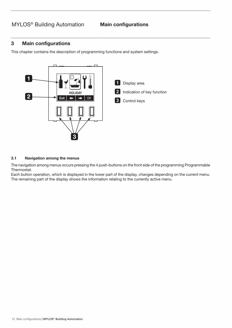
3 Main configurations
This chapter contains the description of programming functions and system settings.
HOLIDAYExit 2 3 OK
3.1 Navigation among the menus
The navigation among menus occurs pressing the 4 push-buttons on the front side of the programming Programmable Thermostat.Each button operation, which is displayed in the lower part of the display, changes depending on the current menu.The remaining part of the display shows the information relating to the currently active menu.
1 Display area
2 Indication of key function
3 Control keys
1
2
3

MYLOS® Building Automation | Main configurations 11
MYLOS® Building Automation Main configurations
3.2 Main screen
The Programmable Thermostat main screen gives information about the temperature regulation of the system.If the Programmable Thermostat is set in automatic operation (default), two different displays are possible: Normal and Zoom are the ones displayed when the device is in automatic operation.
3.2.1 Normal Display
The display shows the date, hour, the temperature measured and the setpoint temperature.
Pressing and releasing one of the 4 front push-buttons the following functions will be displayed:
Mode Repeatedly press the Mode push-button to modify the active temperature regulation setting:
- AUTOMATIC OPERATION: it is the normal operating mode. The Programmable Thermostat carries out temperature adjustment based on a set temporal program;
- STANDBY MODE (heating): the ambient temperature is reduced (e.g. during temporary absence) to save heating costs. The comfort temperature can be restored quickly when necessary. Standby mode (cooling): the ambient temperature is increased (e.g. during temporary absence) to save heating costs. The comfort temperature can be restored quickly when necessary;
- SYSTEM OFF: all temperature regulation functions are disabled;
- MANUAL OPERATION: the setpoint temperature that has been set manually is kept.
Once the desired function has been selected wait a few seconds so that it activates.The display will show the selection made.
1It allows you to manually adjust the setpoint temperature
0
Menu You access the Programmable Thermostat menu which allows you to define all parameters relating to temperature regulation and to carry out the MYLOS Building Automation system configuration.
3.2.2 Zoom Display
The display shows the temperature temporal course based on the program active in automatic operation.
The following function keys are shown:
Exit To go back to the previous menu2 To move along the 45-minute temporal line and display setpoint
temperature course.3
5 It displays the following day.
MONDAY21.0 18.0 15.0
0 1 2 3 4Exit 2 3 5
04.04.11 MON. 12:17
26.5C
SET 15.5(GRAPH)
04.04.11 MON. 12:17
26.5C
SET 15.5Mode 1 0 Menu

12 Main configurations | MYLOS® Building Automation
MYLOS® Building Automation Main configurations
3.3 Menu
By pressing the Menu button the display shows the menu page and the following functions:
Exit To go back to the previous menu.2
To move among menu icons.3
OK To confirm the selected menu.
WARNING:The first 3 icons of the menu concern the temperature regulation settings. The following 3 icons concern the MYLOS Building Automation system configuration.
3.3.1 Party Menu
It allows you to set a constant setpoint temperature for the indicated period.
In this menu the display shows the following functions:
Exit To go back to the previous menu.1 0 To modify the selected value.2 3 To move between duration and setpoint temperatureOK To confirm the settings.
The display shows “PARTY OPERATION” as a confirmation of program execution.
After the set time the system goes back to automatic operation.With the active PARTY menu it is possible to carry out the following functions pressing one of the front push-buttons on the main Programmable Thermostat screen:
- Exit to cancel party operation; - 1 0 to modify setpoint temperature without having to access the menu
again.
HOLIDAYExit 2 3 OK
PARTY
OPERATION
DURATION
03:00TEMPERATURE
22.02 0 1 OK

MYLOS® Building Automation | Main configurations 13
MYLOS® Building Automation Main configurations
3.3.2 Holiday Menu
It allows you to set a constant setpoint temperature until the preset day and hour.
This menu shows the following functions:
Exit To go back to the previous menu.1 0 To modify the selected value.3 To move among different fields.
OK To confirm the settings.The display shows “HOLIDAY OPERATION” as a confirmation of program execution.
Once the preset day and hour have been reached, the system goes back to automatic operation.With the HOLIDAY menu active it is possible to carry out the following functions pressing one of the front push-buttons:
- Exit to cancel party operation; - 1 0 to modify setpoint temperature without having to access the menu
again.
3.3.3 Chrono Menu
It allows you to set system language, date and hour as well as a number of functions that are described in detail in chapter “Air-conditioning control”.
This menu shows the following functions:
Exit To go back to the previous menu1
To scroll the menu down and select the functions0
OK To confirm the selected menu
UNTIL
04. 04. 11 12:00TEMPERATURE
20.0Exit 0 1 3
HOLIDAY
OPERATION
PROGRAMSTEMPERATURESSETTINGSLANGUAGE
Exit 0 OK

14 Main configurations | MYLOS® Building Automation
MYLOS® Building Automation Main configurations
Only the LANGUAGE, DATE and HOUR functions are described below.
3.3.3.1 LANGUAGE menu
It allows you to select the menu display language.Use the arrows 1 0 to move among the fields and confirm using OK.
3.3.3.2 DATE AND HOUR MENU
It allows you to set the system date and hour.Use the arrows 1 0 to modify the selected field, use the arrows 2 3 to move among the fields and confirm using OK.
3.3.4 Events menu
The Events function allows you to logically combine the input channels with a temporal programming to control groups or to recall a SCENE.
This menu shows the following functions:
Exit To go back to the previous menu1
To scroll the menu down and select the program to be customised0
OK To confirm the selected item
You can customise up to 8 different programs.For a detailed description of this menu see chapter “Event management”.
PROGRAM 1PROGRAM 2PROGRAM 3PROGRAM 4
Exit 0 OK
ITALIANOENGLISH
Exit 0 OK
SELECTED LANGUAGE
ITALIANO
17: 19
04. 04. 11
MONDAYExit 0 1 3
CLOCK
SET

MYLOS® Building Automation | Air-conditioning control 15
MYLOS® Building Automation Air-conditioning control
4 Air-conditioning control
The MYLOS Building Automation system allows you to manage air-conditioning during both heating and cooling.Furthermore, the programming Programmable Thermostat can control up to 3 remote thermostats for the climatic control of as many zones (1 master zone + 3 slave zones).
The main air-conditioning control functions occur via the CHRONO Menu.
4.1 PROGRAMS Menu
From this menu it is possible to select the thermostat (local or remote) and the temporal program that you want to use, choosing among 3 fixed programs or 4 programs that can be customised by the user.From the programs menu it is possible to select:
- SELECT it allows you to choose the thermostat (local or remote) that you want to use and the temporal program it should be associated with;
- CUSTOMISE it allows you to create up to 4 customisable temporal programs depending on the user needs.
4.1.1 CUSTOMISE Menu
It allows you to customise the temporal programs:1) select CUSTOMISE and press OK;2) select for example USER 1 and press OK;3) with the arrows 0 1 select the day that you wish to customise (ex. MONDAY) and press OK;4) select MODIFY and press OK;
The display shows the graph representing the temporal course of setpoint temperature levels during the day. - In the upper part the day and hour in which the set temperature level will be applied are displayed. - In the central part the graph with the 3 settable temperature levels (T1, T2, T3) is displayed. T1, T2 and T3 values
can be customised as described in “TEMPERATURES Menu”. - In the lower part the following function keys are displayed:
Exit select NO to exit without saving or YES to save the changes.The message DONE confirms that the changes have been saved.
2 they allow you to select the time interval in which the temperature level can be modified (ex. 02:00 → 02:15).3
4 it allows you to move and select the temperature level (T1, T2, T3) that you wish to program.
SELECTCUSTOMISE
Exit 0 OK
USER 1USER 2USER 3USER 4
Exit 0 OK
USER 1 MONDAY
Exit 0 1 OK
MODIFYCOPY FROM DAY
Exit 0 OK
MON. 02:00 → 02:15T1 T2T3
0 1 2 3 4Exit 2 3 4

16 Air-conditioning control | MYLOS® Building Automation
MYLOS® Building Automation Air-conditioning control
5) select the desired setpoint temperature level, then move forward on the temporal axis using the arrows.Press the key 4 when you wish to change the temperature level.Proceed in this way to create the temporal course for the entire day.
6) exit and save; the display shows the window for temporal course of USER 1, MONDAY.It is now possible to manually set another day or to copy it from an existing day:
1) with the arrows 0 1 select the day that you wish to customise (ex. TUESDAY) and press OK;2) select COPY FROM DAY and press OK;3) using the arrows 0 1 select the day to be copied (ex. MONDAY).
The MONDAY programming will be copied on TUESDAY.4) press OK to confirm; the message DONE confirms that the changes have been saved.
4.1.2 SELECT Menu
It allows you to choose the thermostat (local or remote) that you want to use and the temporal program it should be associated with;
1) select SELECT and press OK;2) select LOCAL to use the thermostat you are adjusting or REMOTE A, B, C, to adjust possible thermostats
located in other rooms, then press OK.The following description applies to both LOCAL and REMOTE sub-menus.
3) choose among the possible temporal programs displayed and press OK: - FIXED 1, 2, 3: they are preset temporal courses that cannot be modified and that can be used as an
alternative to customised courses. - USER 1,2,3,4: they are the temporal courses that can be set by the user as described in “CUSTOMISE Menu”.
4) the graph with the course of the first day of the week is displayed; using the arrows 0 1 it is possible to display all other days and to verify if they correspond to the desired course.
5) press Exit to exit or OK to confirm; a confirmation message will be displayed and the symbol will appear near the programming.
Copy: MONDAYOn: TUESDAY
Exit 0 OK
USER 1 TUESDAY
Exit 0 1 OK
MODIFYCOPY FROM DAY
Exit 0 OK
DONE
SELECTCUSTOMISE
Exit 0 OK
LOCALREMOTE AREMOTE BREMOTE C
Exit 0 OK
FIXED 1FIXED 2FIXED 3USER 1
Exit 0 1 See
FIXED 1MONDAY
Exit 0 1 OK

MYLOS® Building Automation | Air-conditioning control 17
MYLOS® Building Automation Air-conditioning control
4.1.3 SETTINGS Menu
It allows you to customise the following options: - CELSIUS/FAHRENHEIT it allows you to set the display of the unit of measurement for temperature.
4.2 Remote thermostat management
The Programmable Thermostat can manage up to 3 groups of remote thermostats in as many zones.The thermostat, which is remoted for example in the bedroom, receives switching on/off commands and the temperature level it should reach from the Programmable Thermostat.
SUMMER/WINTERCELSIUS/FAHRENHEITHYSTERESISADJUSTMENT MODE
Exit 0 1 OK
CELSIUSFAHRENHEIT
Exit 1 OK
SELECTED SCALE
CELSIUS

18 Event management | MYLOS® Building Automation
MYLOS® Building Automation Event management
5 Event management
Events are temporal programs that allow you to send telegrams based on the input status.An event can also activate a SCENE.The MYLOS Building Automation system allows you to set up to 8 different temporal programs; for each program it is possible to choose which days of the week should be activated and for each day it is possible to set a temporal program.
The management of events occurs via the EVENTS menu. It is therefore necessary to access this menu before proceeding.
5.1 Activating an event
The first operation to be performed is enabling a program or not:1) Select a program (ex. PROGRAM 1) and press OK;2) Select ENABLED and press OK;3) Select ON to enable it, the symbol “” indicates that the function is active;4) Press EXIT to go back to the previous menu;
5.2 Time function management
Through the TIME function, in logic AND with the inputs (if enabled), it is possible to enable a temporal program or not.1) Select TIME and press OK;2) Select ENABLED and press OK;3) Select ON to enable the temporal program.
4) Press ESC to go back to the previous menu;
PROGRAM 1PROGRAM 2PROGRAM 3PROGRAM 4
Exit 0 OK
ENABLEDINPUTSTIMEOUTPUT
Exit 0 OK
OFF ON
Exit 1 OK
ENABLEDINPUTSTIMEOUTPUT
Exit 0 OK
ENABLEDINPUTSTIMEOUTPUT
Exit 0 1 OK
ENABLEDPROGRAM
Exit 0 1 OK
OFF ON
Exit 0 OK

MYLOS® Building Automation | Event management 19
MYLOS® Building Automation Event management
5) Select PROGRAM and press OK;6) With the arrows 0 1 select the day that you wish to customise (ex. MONDAY) and press OK;7) select MODIFY and press OK;
The display shows the graph representing the temporal course of ON and OFF statuses during the day. - In the upper part the day and hour in which the status will be applied are displayed. - In the central part the graph with ON and OFF statuses is displayed. - In the lower part the following function keys are displayed:
Exit select NO to exit without saving or YES to save the changes.The message DONE confirms that the changes have been saved.
2 they allow you to select the time interval in which the event can be activated or deactivated (ex. 02:00 → 02:00).3
4 it allows you to select the ON or OFF status.
8) use the arrows to move forward on the temporal axes and set the status course for the whole day.9) exit and save; the display shows the window for temporal course of PROGRAM 1, MONDAY.
It is now possible to manually set another day or to copy it from an existing day:
1) with the arrows 0 1 select the day that you wish to customise (ex. TUESDAY) and press OK;2) select COPY FROM DAY and press OK;3) using the arrows 0 1 select the day to be copied (ex. MONDAY).
The MONDAY programming will be copied on TUESDAY.4) press OK to confirm; the message DONE confirms that the changes have been saved.
ENABLEDPROGRAM
Exit 0 OK
USER 1 MONDAY
Exit 0 1 OK
MODIFYCOPY FROM DAY
Exit 0 OK
MON. 02:00 → 02:15
ONOFF
0 1 2 3 4Exit 2 3 4
Copy: MONDAYOn: TUESDAY
Exit 0 OK
USER 1Y TUESDAY
Exit 0 1 OK
MODIFYCOPY FROM DAY
Exit 0 OK
DONE

20 Commissioning | MYLOS® Building Automation
MYLOS® Building Automation Commissioning
6 Commissioning
6.1 Parameters
6.1.1 Parameter window “General”
Cyclic sending “In operation” objectOptions:
- No - Cyclic sending value “0” - Cyclic sending value “1”
The “In operation” object reports to the bus that the device is operating correctly. This periodic message can be monitored by an external device. The following parameters are shown:
- transmission period in s [1...65.535] - Options: - 1...60...65.535
The period at which the “In operation” object sends a message periodically is set here.
Enable switchover of temperature display via button °C/°F Options:
- °Celsius - °Fahrenheit
This parameter enables the °C/°F push-switch. The user can then switch the temperature display from °C to °F. The temperature is always converted from °C to °F in the temperature controller with display, because only °C values can be sent to the KNX.

MYLOS® Building Automation | Commissioning 21
MYLOS® Building Automation Commissioning
Display heat/cool is activeOptions:
- If operating mode is active - Always
Operating mode switchover Options:
- 1 Bit (3 x DPT_Switch) - 1 Byte (2 x DPT_HVACmode)
Switching operating mode defines whether the ambient temperature controller has three 1-bit communication objects, “Comfort/Standby”, “Night Mode” or “Freezing/Heat Protection”, or one 1-byte communication objects for switching operating mode.
If an ON message is received by the Comfort/Standby object in 1-bit switching operating mode, the Comfort operating mode is activated.If an OFF message is received Standby mode is activated. If an ON message is received by the Night Mode object, night operating mode is activated. An OFF message deactivates Night Mode. Freezing/Heat Protection mode is also activated with an ON message and deactivated with an OFF message. If an ON message is received by multiple objects, Freezing/Heat Protection has a higher priority than Comfort Mode. Night reduction has a higher priority than Comfort Mode.
The following applies to the 1-byte communication object: 0 = Auto 1 = Comfort 2 = Standby 3 = Night 4 = Freezing/Heat Protection 5 – 255 = not allowed
Operating mode switchingOptions:
- Comfort/Standby - Comfort/Standby/OFF
22 Commissioning | MYLOS® Building Automation
MYLOS® Building Automation Commissioning
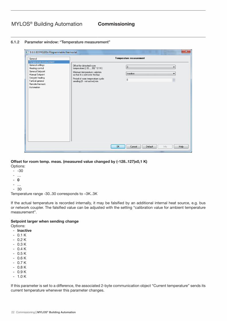
6.1.2 Parameter window: “Temperature measurement”
Offset for room temp. meas. (measured value changed by (-128..127)x0,1 K) Options:
- -30 - … - 0 - … - 30
Temperature range -30..30 corresponds to –3K..3K
If the actual temperature is recorded internally, it may be falsified by an additional internal heat source, e.g. bus or network coupler. The falsified value can be adjusted with the setting “calibration value for ambient temperature measurement”.
Setpoint larger when sending changeOptions:
- Inactive - 0.1 K - 0.2 K - 0.3 K - 0.4 K - 0.5 K - 0.6 K - 0.7 K - 0.8 K - 0.9 K - 1.0 K
If this parameter is set to a difference, the associated 2-byte communication object “Current temperature” sends its current temperature whenever this parameter changes.

MYLOS® Building Automation | Commissioning 23
MYLOS® Building Automation Commissioning
Send setpoint cyclic (0 – inactive, min)Options: - 0 .. 60
If the current value is to be sent cyclically independent of a change, the parameter “Send setpoint cyclic” must be set to a time. This may be necessary, for instance, with a higher-level boiler that expects to receive setpoints and current values within a certain time period. If values are not received, a predefined supply line temperature is set that is no longer oriented on actual demand.
24 Commissioning | MYLOS® Building Automation
MYLOS® Building Automation Commissioning
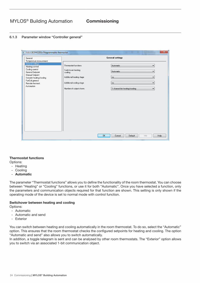
6.1.3 Parameter window “Controller general”
Thermostat functionsOptions:
- Heating - Cooling - Automatic
The parameter “Thermostat functions” allows you to define the functionality of the room thermostat. You can choose between “Heating” or “Cooling” functions, or use it for both “Automatic”. Once you have selected a function, only the parameters and communication objects required for that function are shown. This setting is only shown if the operating mode of the device is set to normal mode with control function.
Switchover between heating and cooling Options:
- Automatic - Automatic and send - Exterior
You can switch between heating and cooling automatically in the room thermostat. To do so, select the “Automatic” option. This ensures that the room thermostat checks the configured setpoints for heating and cooling. The option “Automatic and send” also allows you to switch automatically. In addition, a toggle telegram is sent and can be analysed by other room thermostats. The “Exterior” option allows you to switch via an associated 1-bit communication object.

MYLOS® Building Automation | Commissioning 25
MYLOS® Building Automation Commissioning
Number of output channels Options:
- 1 channel (dual pipe system) for heat / cool - 2 channels (four-pipe system) for heat / cool
If the “Thermostat functions” parameter has been selected, it can be used to specify whether a separate communication object or a common communication object for heating or cooling is provided for the control value. The setting “1 channel (dual pipe system) for heat / cool” is required for dual pipe systems and the setting “2 channels (four-pipe system) for heat / cool” is required for four-pipe systems.

26 Commissioning | MYLOS® Building Automation
MYLOS® Building Automation Commissioning
6.1.4 Parameter window “Heating control”
Status send heat requirement Options:
- Yes - No
If you set the “Status send heat requirement” to “yes”, the ambient temperature controller will send an ON telegram via the relevant 1-bit communication object once it is in heating mode. If the room thermostat is in the “dead zone” between heating and cooling or in cooling mode, the thermostat sends an OFF telegram via the status heating object. This parameter is only available if the “Heating” or “Heat and cool” control functions are set.
Cycle time heating control value sending (0 - inactive, min)Options:
- 0 - 1 - … - 60
The room thermostat can send the control value, even if the value remains unchanged. This is often required since the connected actuator otherwise assumes that the room thermostat is no longer available. This enables the actuator to activate its force-position control, which is only deactivated when a new control value is received. The cycle time for automatic sending of the control value is adjustable from 1 to 60 min. Cyclic sending can also be disabled (setting 0). This parameter is only available if the “Heating” or “Heat and cool” control functions are set.
Control modeOptions:
- 2-step - PWM - Continuous - Fan Coil

MYLOS® Building Automation | Commissioning 27
MYLOS® Building Automation Commissioning
This function allows you to specify the mode of control. You can select “2-step control”, “PWM control”, “Continuous control” or “FanCoil actuation” (see also page 37 and following). This parameter is only available if the “Heating” or “Heat and cool” control functions are set. Note: the fan can be set with a push-switch in Fan Coil only. The push-switch has no function with other control types and fan stage display is hidden.
Hysteresis Options:
- 0.0 K - 0.1 K - 0.2 K - 0.3 K - 0.4 K - … - 1.0 K - … - 2.0 K
Set a hysteresis value to ensure that the valve does not constantly switch with each minor under and overshoot when using 2-step control of the actuator. The hysteresis value lies around the setpoint. For example, if the setpoint is 21 °C and the hysteresis is 1 K, the room thermostat only sends an “on” signal at 21.5 °C and an “off” signal at 20.5 °C. This parameter is only available if “2-step control” is set as the control type.
Invert heating Options:
- Yes - No
“Invert heating” is used to adjust the direction of control action of the control value to “de-energised open” or “de-energised closed” valves. This parameter is only available if “2-step control” is set as the control type.
Control value larger when sending change Options:
- 0% - 1 % - … - 5 % - … - 15 %
The parameter “Control value larger when sending change” can be used to influence the bus load. This setting is configured in percentages. The higher the selected value, the fewer the control value telegrams sent by the room thermostat. However, the value should not be set too high to ensure the control works properly. A value of 5% will generally provide good control results. This parameter is only available if the “Heating” or “Heat and cool” control functions are set and the “Heating” control type is set to “Continuous” or “FanCoil”.

28 Commissioning | MYLOS® Building Automation
MYLOS® Building Automation Commissioning
6.1.14 Remote Thermostat Parameters
6.1.5 Parameter window “Controller PWM heating”
Invert heating Options:
- Yes - No
“Invert heating” is used to adjust the direction of control action of the control value to “de-energised open” or “de-energised closed” valves.
Cycle time PWM control value (min) Options:
- 1 - 2 - … - 10 - … - 60
With PWM control, the actuator switches the valve drive depending on the control value. The control thereby checks the “Cyclic time of the PWM control value”. Example: for a cyclic time of 10 min. and a control value of 60%, the valve gear is switched on for 6 min. and off for 4 min. Basically, the following applies for cyclic time: the more inactive the entire system, the higher the cyclic time you can set.This parameter is only available if the “Heating” or “Heat and cool” control functions are used and the heating control type is set to “PWM”.

MYLOS® Building Automation | Commissioning 29
MYLOS® Building Automation Commissioning
PWM cycle is 0% up to control valueOptions:
- 0% - 5 % - … - 10 % - … - 30 %
If the control value is very small for PWM control, the authorisation period for the actuator might not be sufficient to put in motion the connected thermoelectric valve gear. A valve drive opens or closes by warming or cooling an expansion element. However, it always takes time for the element to heat up or cool off sufficiently to allow the valve to be opened or closed. As a result, the valve might not even open with very small control values. The parameter “PWM cycle is 0% up to control value” can be used to prevent switching with control values that are too small. This parameter allows you to configure the control value that determines actuator authorisation. This parameter is only available if the “Heating” or “Heat and cool” control functions are used and the heating control type is set to “PWM”.
Percentuale massima per il disinserimento della tensione alla valvola termoelettrica Options:
- 70% - 75 % - … - 90 % - … - 100 %
If the control value is very large for PWM control, the switch-off period for the actuator might not be sufficient to put in motion the connected thermoelectric valve gear. A valve drive opens or closes by warming or cooling an expansion element. However, it always takes time for the element to heat up or cool off sufficiently. As a result, the valve might not even close with very large control values. The parameter “PWM cycle is 100% down to an output value” can be used to prevent switching with control values that are too large. It also sets the control value from which the actuator switches off. This parameter is only available if the “Heating” or “Heat and cool” control functions are used and the heating control type is set to “PWM”.

30 Commissioning | MYLOS® Building Automation
MYLOS® Building Automation Commissioning
Control typeOptions:
- 1 bit control - 1 byte control
The additional heating stage can send a 1-bit or 1-byte control value. If “1-bit Switching” is selected, the additional stage controls a switching command (1-bit) via a 1-bit communication object, e.g. a thermoelectric actuator that controls a switching actuator. If “1-bit continuous” is selected, the additional stage carries out a continuous control (1-bit) via a 1-bit communication object, e.g. an electric drive or an actuator with integrated pulse-width modulation. This parameter is only available if the “Heating” or “Heat and cool” control functions are used.
Invert control valueOptions:
- Yes - No
“Invert heating” is used to adjust the direction of control action of the control value to “de-energised open” or “de-energised closed” valves. This parameter is only available if the “Heating” or “Heat and cool” control functions are used.
HysteresisOptions:
- 0.0°C - 0.1°C - 0.2°C - 0.3°C - ……... - 1.0°C - ……… - 2.0°C
6.1.6 Parameter window “Additional heating”

MYLOS® Building Automation | Commissioning 31
MYLOS® Building Automation Commissioning
The parameters “Gap of additional stage” and “Hysteresis (one-sided)” enable you to specify when the additional stage switches on and off. For example, if the additional stage setpoint is 18 °C and the Hysteresis (one-sided) is 0.5 K, the additional stage will activate at 18 °C and will deactivate at 18.5 °C.This parameter is only available if the “Heating” or “Heat and cool” control functions are used.
Cycle time heating control value sending 0…60 minuti (0 – inactive)Options:
- 0 / 1 / 2 / ... / 60
The room thermostat can send a control value, even if the value remains unchanged. This is often required since the connected actuator may assume that the room thermostat is no longer available. This enables the actuator to activate position check.Cycle time for the automatic sending can be set. Cyclic sending can also be disabled.This parameter is only available if the “Heating” or “Heat and cool” control functions are used.
Additional control value interval (0…127)x0.1°COptions:
- 0 - ……... - 30 - ……… - 127
Temperature range 0..127 corresponds to 0C..12.7C
The parameter allows you to specify the additional heating stage setpoint. The setpoint refers to the heating base setpoint (comfort temperature for heating) for the basic stage.Example: the heating base setpoint is 21 °C. When the temperature drops below 18°C, an additional heating should be activated so that the room is heated quickly again. In this case, set the “Level interval for basic level up to additional level” parameter to 3 C. This can be necessary after an automatic night setback, if the user wishes to usethe room immediately (e.g. the bathroom early in the morning).This parameter is only available if the “Heating” or “Heat and cool” control functions are used.

32 Commissioning | MYLOS® Building Automation
MYLOS® Building Automation Commissioning
Control typeOptions:
- 1 bit control - 1 byte control
The additional cooling stage can send a 1-bit or 1-byte control value. If “1-bit Switching” is selected, the additional stage controls a switching command (1-bit) via a 1-bit communication object, e.g. a thermoelectric actuator that controls a switching actuator. If “1-bit continuous” is selected, the additional stage carries out a continuous control (1-bit) via a 1-bit communication object, e.g. an electric drive or an actuator with integrated pulse-width modulation.This parameter is only available if the “Cooling” or “Heat and cool” control functions are used.
Invert control valueOptions:
- Yes - No
The control value is adjusted to “de-energised open” or “de-energised closed” valves via the direction of control action of the controller. This parameter is only available if the “Cooling” or “Heat and cool” control functions are used.
HysteresisOptions:
- 0.0°C - 0.1°C - 0.2°C - 0.3°C - ……... - 1.0°C - ……… - 2.0°C
6.1.7 Parameter window “Additional cooling”

MYLOS® Building Automation | Commissioning 33
MYLOS® Building Automation Commissioning
The parameters “Gap of additional stage” and “Hysteresis (one-sided)” enable you to specify when the additional stage switches on and off. For example, if the setpoint for the additional stage is 29 °C and the hysteresis is 0.5 K (one-sided), the additional stage switches on at 29 °C and off at 28.5 °C.This parameter is only available if the “Cooling” or “Heat and cool” control functions are used.
Cycle time heating control value sending 0…60 minuti (0 – inactive)Options:
- 0 / 1 / 2 / ... / 60
The room thermostat can send a control value, even if the value remains unchanged. This is often required since the connected actuator may assume that the room thermostat is no longer available. This enables the actuator to activate its force-position control, which is only deactivated when a new control value is received.The cycle time for automatic sending of the control value is adjustable. Cyclic sending can also be disabled.This parameter is only available if the “Cooling” or “Heat and cool” control functions are used.
Additional control value interval (0…127)x0.1°COptions:
- 0 - ……... - 30 - ……… - 127
Temperature range 0..127 corresponds to 0C..12.7C
The parameter allows you to specify the additional cooling stage setpoint. The setpoint refers to the cooling base setpoint (comfort temperature for cooling) for the basic level.Example: the cooling base setpoint is 26 °C. When the temperature exceeds 29 °C, additional cooling is activated so that the room is cooled quickly again. In this case, set the “Level interval for basic level up to additional level” parameter to 3°C. This parameter is only available if the “Cooling” or “Heat and cool”control functions are used.

34 Commissioning | MYLOS® Building Automation
MYLOS® Building Automation Commissioning
6.1.8 Parameter window “Setpoint general”
Setpoint larger when sending changeOptions:
- Inactive - 0.1 K - 0.2 K - 0.3 K - 0.4 K - 0.5 K - 0.6 K - 0.7 K - 0.8 K - 0.9 K - 1.0 K
If this parameter is set to a difference, the associated 2-byte communication object “Setpoint temperature” sends its current temperature whenever this parameter changes more than the specified difference.
Cyclic sending of setpoint (0 – inactive, min)Options:
- 0 - 1 - 2 - … - 60
If the setpoint is to be sent cyclically independent of a change, the parameter “Cyclic sending of setpoint” must be set to a time. This may be necessary, for instance, with a higher-level boiler that expects to receive setpoints and current values within a certain time period. If values are not received, a predefined supply line temperature is set that is no longer oriented on actual demand.

MYLOS® Building Automation | Commissioning 35
MYLOS® Building Automation Commissioning
Select base setpointOptions:
- Dependent setpoints - Individual setpoints
The “Select base setpoint” option defines whether the room thermostat refers to “Dependent setpoints” or to “Single setpoints”.Dependent setpoints mean that a comfort temperature (base setpoint) is defined and other setpoints such as temperature at standby or automatic night setback refer to this temperature.The standby temperature 2 K is set lower than the comfort temperature (base setpoint). At a comfort temperature of 21 °C this means a standby temperature of 19 °C. If you raise the comfort temperature to 22 °C by manually moving the setpoint, the standby temperature is automatically changed to 20 °C.The setting “Single setpoints” allows you to choose a separate temperature on the room thermostat for each setpoint; the room thermostat always refers to this setting in the respective operating mode.Example: the standby temperature is set permanently at 19 °C. If you raise the comfort temperature from 21 °C to 22 °C by manually moving the setpoint, the standby temperature does not change.
Reference base setpointOptions:
- Setpoint heating - Setpoint cooling - Mid zone of the dead zone
If “Dependent setpoints” were selected with “Heat and cool” controller function and selection of base setpoint, this parameter can be used to define whether the base setpoint refers to comfort temperature for heating, cooling or the average temperature between “Heat and cool” (see also page 71, Section 7.4.3 Minimum interval).“Setpoint heating” is the default setting. In regions where the cooling function is more important, it is recommended that you change this parameter to “Setpoint cooling”. This makes it easier to set the room thermostat and raise the cooling setpoint (standby temperature cooling and automatic night setback).This parameter is only available if the “Heat and cool” control functions are set.
Manual setpoint adjustment at reset of change from night / to nightOptions:
- Yes - No
If this parameter is set to “Yes”, the setpoint offset is automatically reset when switching operating modes from night and to night.If a setpoint is adjusted manually, the increase or reduction of the setpoint can be cancelled if the operating mode is changed, e.g. on receipt of a telegram from a timer. This means that if the parameter is set to “Yes”, the manually adjusted setpoint will be rejected if the operating mode changes and it will be reset to the setpoint preset in the parameter.

36 Commissioning | MYLOS® Building Automation
MYLOS® Building Automation Commissioning
6.1.9 Parameter window “Manual setpoint”
Manual setpoint adjustment Options:
- Disabled - Active
This parameter allows end users to adjust the configured setpoint during commissioning. The settings “... manual increase and reduction of the setpoint” is used to specify how high or low the setpoint can be moved. The value that is parametrised for manually configuring the setpoint is an amount that fluctuates around the setpoint.Example: with a comfort temperature of 21 °C and a manual setpoint adjustment of +/- 3 K, users can select any temperature from 18 °C to 24 °C.
Maximum manual setpoint increase Options:
- 0 K - 1 K - 2 K - 3 K - 4 K - 5 K - 6 K - 7 K - 8 K - 9 K - 10 K
If you wish to prevent an excessive temperature increase by the manual setpoint setting, the upper range of the manual setpoint preset can be limited with the parameter “Maximum manual setpoint increase”. Example: with a comfort heating temperature of 21 °C and a manual setpoint adjustment of +/- 3 K, users can select any temperature from 18 °C to 24 °C. If the comfort temperature can be increased to a maximum of 22 °C, enter “1 K” under the parameter “Max. increase of setpoint”.

MYLOS® Building Automation | Commissioning 37
MYLOS® Building Automation Commissioning
Maximum manual setpoint reduction Options:
- 0 K - 1 K - 2 K - 3 K - 4 K - 5 K - 6 K - 7 K - 8 K - 9 K - 10 K
If you wish to prevent an excessive temperature reduction by the manual setpoint setting, the lower range of the manual setpoint preset can be limited with the parameter “Maximum manual setpoint reduction”. Example: with a comfort cooling temperature of 26 °C and a manual setpoint adjustment of +/- 3 K, users can select any temperature from 23 °C to 29 °C. If the comfort temperature can be reduced to a maximum of 25 °C, enter “1 K” under the parameter “Max. reduction of setpoint”.
Object reset of manual setpoint adjustment active Options:
- Yes - No
This parameter releases a 1-bit communication object that upon receipt of an ON telegram can be used manually reset the setpoint adjustment. This is required, for instance, if a central function is triggered that is intended to reset all the room thermostats to their default settings. All manual setpoint adjustments are rest for both “dependent” setpoints and “individual” setpoints.
When receiving base setpoint Options:
- Retain manual setpoint adjustment - Reset manual setpoint adjustment
If a new base setpoint is received by the ambient temperature controller via KNX telegram after manually adjusting the setpoint, the ambient temperature controller can also reset the manually adjusted setpoint. The behaviour of the ambient temperature controller when receiving a base setpoint value can be configured via this parameter. The manually configured setpoint is either reset or remains unchanged. This refers to all setpoints for “dependent” setpoints and the base setpoint that was received for “individual” setpoints, e.g. “heating setpoint comfort mode”.

38 Commissioning | MYLOS® Building Automation
MYLOS® Building Automation Commissioning
6.1.10 Parameter window “Setpoint heat/cool”
Heating setpoint comfort modeOptions:
- 16.0 °C - 16.5 °C - … - 21.0 °C - … - 31.0 °C
The “Heating setpoint comfort mode” specifies the individual comfort temperature for the heating mode. This parameter is only available if the “Heating” or “Heat and cool” control functions are used, in which the setpoints “Dependent setpoints” (tab “Setpoints general”) have been selected and the reference of the base setpoint has been set to “Base setpoint heating”.
Heating setpoint reduction standbyOptions:
- 0.5 K - 1.0 K - … - 2 K - … - 8.0 K
The setting “Heating setpoint reduction standby” allows you to specify the number of degrees Kelvin that the comfort temperature is lowered during standby operation.This parameter is only available if the parameter “Selection of base setpoint” (tab “Setpoint general”) is set to “Dependent setpoints”.

MYLOS® Building Automation | Commissioning 39
MYLOS® Building Automation Commissioning
Heating setpoint reduction night operationOptions:
- 0.5 K - 1.0 K - … - 4 K - … - 8.0 K
The setting “Heating setpoint reduction night operation” allows you to specify the number of degrees Kelvin that the comfort temperature is lowered during night mode.This parameter is only available if the parameter “Selection of base setpoint” (tab “Setpoint general”) is set to “dependent setpoints”.
Cooling setpoint comfort modeOptions:
- 16.0 °C - 16.5 °C - … - 23.0 °C - … - 31.0 °C
The “Cooling setpoint comfort mode” specifies the individual comfort temperature for the cooling mode. This parameter is only available if the “Cooling” or “Heat and cool” control functions are used, in which the setpoints “dependent setpoints” (tab “Setpoints general”) have been selected.
Cooling setpoint increase standbyOptions:
- 0.5 K - 1.0 K - … - 2 K - … - 8.0 K
The setting “Cooling setpoint increase standby” allows you to specify the number of degrees Kelvin that the comfort temperature is increased during standby operation.This parameter is only available if the parameter “Selection of base setpoint” (tab “Setpoint general”) is set to “Dependent setpoints”.
Cooling setpoint increase night modeOptions:
- 0.5 K - 1.0 K - … - 4 K - … - 8.0 K
“Cooling setpoint increase night mode” allows you to specify the number of degrees Kelvin that the comfort temperature is raised during night operation. This parameter is only available if the parameter “Selection of base setpoint” (tab “Setpoint general”) is set to “Dependent setpoints”.

40 Commissioning | MYLOS® Building Automation
MYLOS® Building Automation Commissioning
Minimum distance between heating setpoint and cooling setpointOptions:
- 0.0 K - 0.5 K - ... - 2 K - ... - 7.5 K
The comfort temperature for cooling can be adjusted with “Minimum distance between heating and cooling”.If, for instance, with a comfort temperature (base setpoint) of 21 °C you want to cool at 26 °C in comfort mode, you have to set a dead zone of 5 K (see also page 95 Section 4.4.3 Minimum distance).This parameter is only available if the parameter “Selection of base setpoint” (tab “Setpoint general”) is set to “Dependent setpoints”.
Setpoint frost protectionOptions:
- 0 °C - … - 7 °C - … - 15 °C
The setpoint for frost protection is the temperature that may not be undershot during the frost protection mode. If the current temperature undershoots the configured value, the ambient temperature controller triggers a control value telegram that causes the relevant heating actuator to heat up the room to prevent damage to the heating system from frost-related cooling.This parameter is only available if the “Heating” or “Heat and cool” control functions are used.
Setpoint heat protectionOptions:
- 30.0 °C - 30.5 °C - … - … - 44.0 °C - Cooling disabled
The setpoint for heat protection is the temperature that may not be overshot during heat protection mode. If the current temperature overshoots the configured value, the ambient temperature controller triggers a control value telegram that causes the relevant cooling unit to cool the room to prevent damage from heat build-up.This parameter is only available if the “Cooling” or “Heat and cool” control functions are used.
Note: At the setpoint 99.9 °C is sent at “Cooling disabled”.

MYLOS® Building Automation | Commissioning 41
MYLOS® Building Automation Commissioning
6.1.11 Parameter window “FanCoil general”
Number of fan levelsOptions:
- 1 level - 2 levels - 3 levels
The parameter “Number of fan levels” allows you to specify the number of fan stages that should be controlled for a fan coil actuator. You can select from one, two or three stages. The ambient temperature controller always provides a 1-byte communication object (see object: “Send manual fan level” has the following coding) and also provides exactly as many 1-bit communication objects as the number of fan stages selected. Most importantly, the number selected must match the actual number of fan stages. An actuator is therefore actuated either by the 1-byte communication object or the 1-bit communication object.
Manual operation of the fan stage is signalled to the actuator viaOptions:
- Object “Automatic ON/OFF...” - Object “Manual ON/OFF...”
This specifies which object sends the information to the actuator or whether the fan stage is being manually operated by the user. The only difference between the objects is the coding.“Automatic ON/OFF” = 1, if manual operation is not enabled“Manual ON/OFF” = 1, if manual operation is not enabled
Object manual fan stage send has the following codeOptions
- 1-Byte object as constant value 0-100% - 1-Byte object as counting value 0-3 - 1-Bit Values
If the user has made a manual fan stage switch, it can be sent to the KNX.

42 Commissioning | MYLOS® Building Automation
MYLOS® Building Automation Commissioning
The parameter “Manual fan stage send has the following code” can be used to enable a 1-byte object or three 1-bit objects.The selected fan stage can be sent via the 1-byte object as a counter value from 0 to 3 (0=no manual switch) or the continuous value from 0 to 100 %.The continuous values for output are specified by the settings in the threshold values for the specific stage.When 1-bit values are selected, a 1-bit communication object is available for every fan stage. If the fan stage is manually switched, an OB telegram is sent via the corresponding object. An OFF telegram is sent if the manual switch is cancelled.
Send cycle time of actuator in s (0 ... 65535) sec (0 - disab)Options:
- 1 - 2 - … - 120 - … - 65,535
If the “Status byte operation” object is enabled and connected to the corresponding communication object of the fan coil actuator, the ambient temperature controller expects a cyclic transmission of the operating status of the linked fan coil actuator. If a message from the actuator is not sent within the monitoring time “Send cycle time of actuator in s” at least once, the ambient temperature controller automatically shows the fault display. The cycle time of the actuator should therefore be set to ensure that a telegram is sent at least twice during “Send cycle time of actuator in s (0 ... 65535) sec (0 - disab)”.
Stage of fan after resetOptions:
- Off - Stage 1 - Level 2 - Level 3 - Automatic
The parameter “Stage of fan after reset and after off” is used to prevent undefined states after a reset or switching off the ambient temperature controller. It specifies whether the fan switches on the first, second or third stage, switches off or switches to automatic mode.
Note:Automatic mode means that the fan coil actuator switches the fan stages based on the received 1-byte control value.

MYLOS® Building Automation | Commissioning 43
MYLOS® Building Automation Commissioning
6.1.12 Parameter window “FanCoil heating”
Step limit in night modeOptions:
- No limit - Fan Off - Level 1 - Level 2
If the device is used in an environment such as a hotel room, it may be desirable to limit the fan stages during the night to reduce the noise.The parameter “Stage limit in night mode” is used for this. If the parameter is set to stage 1, the fan will not use more that the first stage when night mode is enabled. This will apply even if the transmitted control value requests a higher fan stage.
Automatic return from manual adjustment (0 - inactive, min)Options:
- 0 - 1 - 2 - … - 60
If “Manual stage switching” was performed by the user, this action can be reset via onsite operation of the ambient temperature controller.However, a time can also be input after which the ambient temperature cancels the “Manual stage switching” and switches back to automatic stage switching mode.This parameter is only available if the “Heating” or “Heat and cool” control functions are used and the heating control type is set to “FanCoil”.

44 Commissioning | MYLOS® Building Automation
MYLOS® Building Automation Commissioning
Return inactive a fan stage of and automatic return not 0Options:
- Yes - No
If the user has manually changed the stage to “switch off”, the ambient temperature controller can also be set so that it does not return to automatic switching at the end of the “manual switching period” but rather remains switched off.This parameter is only available if the “Heating” or “Heat and cool” control functions are used and the heating control type is set to “FanCoil”.
Threshold value stage 1Options:
- 0% - 10 % - … - 50 % - … - 100 %
Threshold value stage 1 specifies the magnitude of the control value required to switch the ambient temperature controller to fan stage 1.The threshold can be defined in percentages. Make sure that the threshold for stage 1 is not set higher than the threshold for stage 2 (if available).This parameter is only available if the “Heating” or “Heat and cool” control functions are used, the heating control type is set to “FanCoil” and the number of fan stages is min. “1 stage”.
Threshold value stage 2Options:
- 0% - 10 % - … - 40 % - … - 100 %
Threshold value stage 2 specifies the magnitude of the control value required to switch the ambient temperature controller from fan stage 1 to fan stage 2. The threshold can be defined in percentages. Make sure that the threshold for stage 1 is not set higher than the threshold for stage 2 (if available). This parameter is only available if the “Heating” or “Heat and cool” control functions are used, the heating control type is set to “FanCoil” and the number of fan stages is min. “2 stage”.
Threshold value stage 3Options:
- 0% - 10 % - … - 70 % - … - 100 %
Threshold value stage 3 specifies the magnitude of the control value required to switch the ambient temperature controller from fan stage 2 to fan stage 3. The threshold can be defined in percentages. Make sure that the threshold for stage 3 is not set higher than the threshold for stage 3 (if available).This parameter is only available if the “Heating” or “Heat and cool” control functions are used, the heating control type is set to “FanCoil” and the number of fan stages is min. “3 stage”.

MYLOS® Building Automation | Commissioning 45
MYLOS® Building Automation Commissioning
6.1.13 Parameter window “FanCoil cooling”
Step limit in night modeOptions:
- No limit - Fan Off - Level 1 - Level 2
If the device is used in an environment such as a hotel room, it may be desirable to limit the fan stages during the night to reduce the noise.The parameter “Stage limit in night mode” is used for this. If the parameter is set to stage 1, the fan will not use more that the first stage when night mode is enabled. This will apply even if the transmitted control value requests a higher fan stage.
Automatic return from manual adjustment (0 - inactive, min)Options:
- 0 - 1 - 2 - … - 60
If “Manual stage switching” was performed by the user, this action can be reset via onsite operation of the ambient temperature controller.However, a time can also be input after which the ambient temperature cancels the “Manual stage switching” and switches back to automatic stage switching mode.This parameter is only available if the “Cooling” or “Heat and cool” control functions are used and the cooling control type is set to “FanCoil”.

46 Commissioning | MYLOS® Building Automation
MYLOS® Building Automation Commissioning
Return inactive a fan stage of and automatic return not 0Options:
- Yes - No
If the user has manually changed the stage to “switch off”, the ambient temperature controller can also be set so that it does not return to automatic switching at the end of the “manual switching period” but rather remains switched off.This parameter is only available if the “Cooling” or “Heat and cool” control functions are used and the heating control type is set to “FanCoil”.
Threshold value stage 1Options:
- 0% - 10 % - … - 50 % - … - 100 %
Threshold value stage 1 specifies the magnitude of the control value required to switch the ambient temperature controller to fan stage 1.The threshold can be defined in percentages. Make sure that the threshold for stage 1 is not set higher than the threshold for stage 2 (if available).This parameter is only available if the “Cooling” or “Heat and cool” control functions are used, the heating control type is set to “FanCoil” and the number of fan stages is min. “1 stage”.
Threshold value stage 2Options:
- 0% - 10 % - … - 40 % - … - 100 %
Threshold value stage 2 specifies the magnitude of the control value required to switch the ambient temperature controller from fan stage 1 to fan stage 2. The threshold can be defined in percentages. Make sure that the threshold for stage 2 is not set higher than the threshold for stage 3 (if available). This parameter is only available if the “Cooling” or “Heat and cool” control functions are used, the heating control type is set to “FanCoil” and the number of fan stages is min. “2 stage”.
Threshold value stage 3Options:
- 0% - 10 % - … - 70 % - … - 100 %
Threshold value stage 3 specifies the magnitude of the control value required to switch the ambient temperature controller from fan stage 2 to fan stage 3. The threshold can be defined in percentages. Make sure that the threshold for stage 3 is not set higher than the threshold for stage 3 (if available).This parameter is only available if the “Cooling” or “Heat and cool” control functions are used, the heating control type is set to “FanCoil” and the number of fan stages is min. “3 stage”.

MYLOS® Building Automation | Commissioning 47
MYLOS® Building Automation Commissioning
The Programmable Thermostat can control up to three remote thermostats depending on the modes settable from parameters.
Enable area x
Options: - No - Yes
Area x control modeOptions:
- Mode - Setpoint only - Setpoint + comfort
The Enable zone x parameter enables the control of the three possible thermostats.The Zone x control mode parameter allows you to select the mode in which the Programmable Thermostat can send control telegrams to the thermostat. The Mode parameter indicates the sending only for messages indicating the current operating mode of the Programmable Thermostat (auto, comfort, standby…). Setpoint only sends only the setpoint value currently selected on the Programmable Thermostat. Setpoint + comfort sends the Programmable Thermostat setpoint and the comfort operating mode.

48 Commissioning | MYLOS® Building Automation
MYLOS® Building Automation Commissioning
6.1.15 Automation Parameters
This parameter set allows you to set up to eight possible events, controlled depending of the status of the corresponding communication objects “Input A” and “Input B”.
In the “Automation 1/8” control window it is possible to make the Programmable Thermostat implement different function types that it will carry out automatically communicating with one or more associated remote devices.

MYLOS® Building Automation | Commissioning 49
MYLOS® Building Automation Commissioning
6.2 Automation Parameters
Output typeOptions:
- On/off - Recall scene - Shutter - Percentage value
6.2.1 On/Off configuration
If “Output type” is configured as “On/Off”, the Programmable Thermostat can send a value that can be set from the parameter to a specific output switching status via the corresponding communication objects.
Upon switching offOptions:
- no reaction - send telegram
It allows you to send or not to send the control telegram.
Upon switching onOptions:
- no reaction - send telegram
It allows you to send or not to send the control telegram.

50 Commissioning | MYLOS® Building Automation
MYLOS® Building Automation Commissioning
6.2.2 Recall Scene configuration
If “Output type” is configured as “Recall Scene”, the Programmable Thermostat has the possibility to send the scene value to be recalled.
Recall scene Options:
- values from 0 to 255

MYLOS® Building Automation | Commissioning 51
MYLOS® Building Automation Commissioning
6.2.3 Shutter configuration
If “Output type” is configured as “Shutter”, the Programmable Thermostat has the possibility to control a shutter actuator.
Upon switching offOptions:
- no reaction - send telegram
It allows you to send or not to send the control telegram.
Upon switching onOptions:
- no reaction - send telegram
It allows you to send or not to send the control telegram.

52 Commissioning | MYLOS® Building Automation
MYLOS® Building Automation Commissioning
6.2.4 Percentage Value configuration
If “Output type” is configured as “Percentage value”, the Programmable Thermostat has the possibility to send the value that can be set by the parameter.
Upon switching offOptions:
- no reaction - send telegram
It allows you to send or not to send the telegram.
Upon switching onOptions:
- no reaction - send telegram
It allows you to send or not to send the telegram.

MYLOS® Building Automation | Commissioning 53
MYLOS® Building Automation Commissioning
6.2.5 Logic function
The output value of the Programmable Thermostat can be conditioned by the application of a logic function that involves one or two logic inputs.
Logic FunctionOptions:
- 1 object - 2 objects
The parameter allows you to select the number of logic inputs that are estimated by the logic function. If 1 object, the values remains unchanged on logic function output.
6.2.6 Enable Time function
The Programmable Thermostat has the possibility of managing the daily temporal programs. These programs allow you to enable the logic output of the Programmable Thermostat based on the temporal program.
Enable Time functionOptions:
- on - off
Enable or disable the time function.

54 Commissioning | MYLOS® Building Automation
MYLOS® Building Automation Commissioning
6.3 Communication objects
6.3.1 General
No. Function Object name Type of datum Flags
0 In operation General 1 bit EIS1 DPT 1.001 C,T
Sends the object value „0“ or „1“ to the bus cyclically. Object value and cycle time can be set in the parameters. The telegram can be used for monitoring the device operation, e.g. by a monitoring block.
19 Device On / Off General 1 bit EIS1 DPT 1.001 C,R,W,T
The controller is activated via this 1-bit communication object when an ON telegram is received and deactivated when an OFF telegram is received. It can receive and send. Switching the controller on and off is the same as actuating the ON/OFF switch on the device. When the device is switched off OFF is shown on the display, but the controller setpoint is switched to a parametrisable temperature setpoint and the fan switches off immediately. 0: switch off device or device is switched off 1: switch on device or device is switched on

MYLOS® Building Automation | Commissioning 55
MYLOS® Building Automation Commissioning
6.3.2 Operating mode
No. Function Object name Type of datum Flags
1 Frost/heat protection Operating mode 1 bit EIS1 DPT 1.001 C,R,W
This data item forms the 1-bit object of KNX for switching operating modes (frost and heat protection). It can be received only. For example, binary inputs that record information from window contacts to notify the ambient temperature controller that a window is open or closed can send their current status to the frost and heat protection object. When receiving an ON telegram, the room thermostat activates frost protection mode; when an OFF telegram is received, frost protection mode is deactivated and the current mode is changed. The „window“ symbol is shown in the display when frost/heat protection is enabled. 0: Frost/Heat Protection Off 1: Frost/Heat Protection On
2 Night mode Operating mode 1 bit EIS1 DPT 1.001 C,R,W
This 1-bit communication object can be used to switch the room thermostat to night mode when an ON telegram is received. An OFF telegram deactivates night mode. This communication object can be used, e.g., by time switches to send information. This data item forms the 1-bit object of KNX for switching operating modes (night mode). It can be received only, because a manual switch to night mode on site is not possible. In night mode the parametrisable setpoint „night mode“ is enabled and the fan stage is limited to a parametrisable value. 0: night mode Off 1: night mode On
3 Comfort/standby mode Operating mode 1 bit EIS1 DPT 1.001 C,R,W
This 1-bit communication object can be used to switch the room thermostat to comfort mode when an ON telegram is received. An OFF telegram deactivates comfort mode and activates standby mode. This communication object can be used, e.g., by time switches to send information. This data item forms the 1-bit object of KNX for switching operating modes (comfort/standby mode). 0: standby mode Off / comfort mode On 1: standby mode On / comfort mode Off
5 Auto mode Operating mode 1 bit EIS1 DPT 1.001 C,R,W
This 1-bit communication object can be used to switch the room thermostat to auto mode when an ON telegram is received. An OFF telegram deactivates auto mode. This communication object can be used, e.g., by time switches to send information. This data item forms the 1-bit object of KNX for switching operating modes (auto mode). 0: auto mode Off 1: auto mode On

56 Commissioning | MYLOS® Building Automation
MYLOS® Building Automation Commissioning
6 Party mode Operating mode 1 bit EIS1 DPT 1.001 C,R,W
This 1-bit communication object can be used to deactivate party mode when an ON telegram is received. This communication object can be used, e.g., by time switches to send information. This data item forms the 1-bit object of KNX for switching operating modes (party mode). 0: party mode Off
7 Holiday mode Operating mode 1 bit EIS1 DPT 1.001 C,R,W
This 1-bit communication object can be used to deactivate holiday mode when an ON telegram is received. This communication object can be used, e.g., by time switches to send information. This data item forms the 1-bit object of KNX for switching operating modes (holiday mode). 0: holiday mode Off
8 Operating mode switching Operating mode 1 byte EIS1 DPT 20.102
C,R,W
This data item forms the 1-bit object of KNX (DPT_HVAC_MODE) for switching operating modes. All operating modes of the above 1-bit objects can be set with the 1-byte object. The data item can be received and sent. The selection of whether switching is via three 1-bit objects or two 1-byte objects (OMN / OMO) is defined by application parameters (see above). This 1-byte communication object can be used to switch between comfort, standby, night and frost/heat protection modes. The object evaluates received telegrams as „normal“. This means, for example, if a comfort telegram is received, the room thermostat switches to comfort mode. If a night telegram is received, the room thermostat switches to night mode. This object is controlled, for example, by time switches. The following provisions apply for the object: 0: Auto 1: Comfort 2: Standby 3: Night 4: Frost/Heat Protection5: Party6: Holiday 7 – 255: not allowed
26 Exter. via object Switching Operating mode 1 bit EIS1 DPT 1.001 C,R,W,T
This data item forms the 1-bit KNX object. It can be received and sent. If the RTR switches the operating mode, the object is sent if the corresponding parameter has been set to „automatic and send“. In the event of external switching the operating mode is switched by a different bus device (such as a fan coil 2-line system). After the switching a separate output object or the same output object can be used (depending on the number of output channels with „heating and cooling“). 0: cooling 1: heating

MYLOS® Building Automation | Commissioning 57
MYLOS® Building Automation Commissioning
6.3.3 Adjustment
No. Function Object name Type of datum Flags
9 Temperature sending Adjustment 2 byte EIS1 DPT 9.001 C,R,T
This data item forms the 2-byte object of KNX for the current temperature. The temperature is measured in the „temperature sensor“ application and can be weighted with an external input temperature (object input for external current temperature). It can be sent only. Must be cyclic and be able to send on change.
10 Heating status Adjustment 1 bit EIS1 DPT 1.001 C,R,W,T
This data item acts as an output and provides information on whether the ehating output is currently enabled (including in the switched-off phases of a PWM cycle). This information can be useful for visualisation.
11 High additional heat. adj. Adjustment 1 byte / 1 bit C,R,T
This data item forms the 1-byte or 1-bit KNX object and can be sent only. This object represents the control value for the additional heating stage (switching or quasi-continuous).
12 Cooling status Adjustment 1 bit EIS1 DPT 1.001 C,R,T
This data item acts as an output and provides information on whether the cooling output is currently enabled (including in the switched-off phases of a PWM cycle). This information can be useful for visualisation.
13 High heat. adj. (switching) Adjustment 1 bit EIS1 DPT 1.001 / 1 byte EIS1 DPT 5.001
C,R,T
2 channel (4-pipe system) This data item forms the 1-byte or 1-bit KNX object and can be sent only. This object is the control value for heating. In fan coil systems with only one output channel it is the „heating/cooling“ object in which the internal allocation is controlled by the external operating mode switching (see index 6). When acting as a branch the control value is received via this object.
14 High cool. adj. (switching) Adjustment 1 bit EIS1 DPT 1.001 / 1 byte EIS1 DPT 5.001
C,R,T
This data item forms the 1-byte or 1-bit KNX object and can be sent only. This object is the control value for cooling. This object is used with 2 channels (4-pipe system) only. When acting as a branch the control value is received via this object.
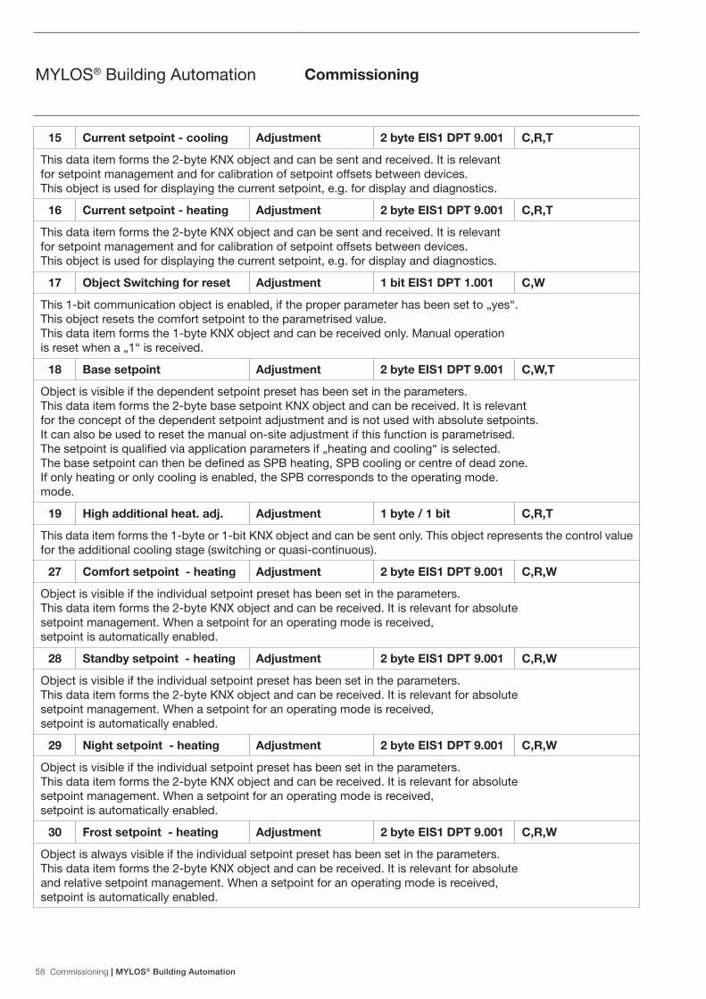
58 Commissioning | MYLOS® Building Automation
MYLOS® Building Automation Commissioning
15 Current setpoint - cooling Adjustment 2 byte EIS1 DPT 9.001 C,R,T
This data item forms the 2-byte KNX object and can be sent and received. It is relevant for setpoint management and for calibration of setpoint offsets between devices. This object is used for displaying the current setpoint, e.g. for display and diagnostics.
16 Current setpoint - heating Adjustment 2 byte EIS1 DPT 9.001 C,R,T
This data item forms the 2-byte KNX object and can be sent and received. It is relevant for setpoint management and for calibration of setpoint offsets between devices. This object is used for displaying the current setpoint, e.g. for display and diagnostics.
17 Object Switching for reset Adjustment 1 bit EIS1 DPT 1.001 C,W
This 1-bit communication object is enabled, if the proper parameter has been set to „yes“. This object resets the comfort setpoint to the parametrised value. This data item forms the 1-byte KNX object and can be received only. Manual operation is reset when a „1“ is received.
18 Base setpoint Adjustment 2 byte EIS1 DPT 9.001 C,W,T
Object is visible if the dependent setpoint preset has been set in the parameters. This data item forms the 2-byte base setpoint KNX object and can be received. It is relevant for the concept of the dependent setpoint adjustment and is not used with absolute setpoints. It can also be used to reset the manual on-site adjustment if this function is parametrised. The setpoint is qualified via application parameters if „heating and cooling“ is selected. The base setpoint can then be defined as SPB heating, SPB cooling or centre of dead zone. If only heating or only cooling is enabled, the SPB corresponds to the operating mode. mode.
19 High additional heat. adj. Adjustment 1 byte / 1 bit C,R,T
This data item forms the 1-byte or 1-bit KNX object and can be sent only. This object represents the control value for the additional cooling stage (switching or quasi-continuous).
27 Comfort setpoint - heating Adjustment 2 byte EIS1 DPT 9.001 C,R,W
Object is visible if the individual setpoint preset has been set in the parameters. This data item forms the 2-byte KNX object and can be received. It is relevant for absolute setpoint management. When a setpoint for an operating mode is received, setpoint is automatically enabled.
28 Standby setpoint - heating Adjustment 2 byte EIS1 DPT 9.001 C,R,W
Object is visible if the individual setpoint preset has been set in the parameters. This data item forms the 2-byte KNX object and can be received. It is relevant for absolute setpoint management. When a setpoint for an operating mode is received, setpoint is automatically enabled.
29 Night setpoint - heating Adjustment 2 byte EIS1 DPT 9.001 C,R,W
Object is visible if the individual setpoint preset has been set in the parameters. This data item forms the 2-byte KNX object and can be received. It is relevant for absolute setpoint management. When a setpoint for an operating mode is received, setpoint is automatically enabled.
30 Frost setpoint - heating Adjustment 2 byte EIS1 DPT 9.001 C,R,W
Object is always visible if the individual setpoint preset has been set in the parameters. This data item forms the 2-byte KNX object and can be received. It is relevant for absolute and relative setpoint management. When a setpoint for an operating mode is received, setpoint is automatically enabled.

MYLOS® Building Automation | Commissioning 59
MYLOS® Building Automation Commissioning
31 Comfort setpoint - cooling Adjustment 2 byte EIS1 DPT 9.001 C,R,W
Object is visible if the individual setpoint preset has been set in the parameters. This data item forms the 2-byte KNX object and can be received. It is relevant for absolute setpoint management. When a setpoint for an operating mode is received, setpoint is automatically enabled.
32 Standby setpoint - cooling Adjustment 2 byte EIS1 DPT 9.001 C,R,W
Object is visible if the individual setpoint preset has been set in the parameters. This data item forms the 2-byte KNX object and can be received. It is relevant for absolute setpoint management. When a setpoint for an operating mode is received, setpoint is automatically enabled.
33 Night setpoint - cooling Adjustment 2 byte EIS1 DPT 9.001 C,R,W
Object is visible if the individual setpoint preset has been set in the parameters. This data item forms the 2-byte KNX object and can be received. It is relevant for absolute setpoint management. When a setpoint for an operating mode is received, setpoint is automatically enabled.
34 Heat setpoint - cooling Adjustment 2 byte EIS1 DPT 9.001 C,R,W
Object is always visible if the individual setpoint preset has been set in the parameters. This data item forms the 2-byte KNX object and can be received. It is relevant for absolute and relative setpoint management. When a setpoint for an operating mode is received, setpoint is automatically enabled. Value 99.9 means heat protection = off.
35 Receiving current status Adjustment 1 bit EIS1 DPT 1.001 C,R,W
This 1-bit communication object is enabled, if the proper parameter has been set to „yes“. This object resets the comfort setpoint to the parametrised value. This data item forms the 1-byte KNX object and can be received only. Manual operation is reset when a „1“ is received.

60 Commissioning | MYLOS® Building Automation
MYLOS® Building Automation Commissioning
6.3.4 Fan coil auto/manual
No. Function Object name Type of datum Flags
20 Auto on/off Fan auto/man 1 bit EIS1 DPT 1.001 C,R,W,T
If a fan coil actuator is tripped by the ambient temperature controller, the individual fan stages are typically switched automatically by the room thermostat. However, users can select a stage manually. When the stage is specified manually, the 1-bit communication object triggers an ON telegram and when manual mode is deactivated, an OFF telegram is sent. This enables you to notify a second control unit that a stage has been set manually. The 1-bit object can also receive and analyse telegrams sent from other control points. This data item forms the 1-bit KNX object and can be sent and received. When switching to manual operation and sending a fan stage via the display, manual mode is enabled. Automatic mode is re-enabled with this data item after automatic return after a parametrisable time. For example, if an automatic return is not to be parametrised, the RTR can be reset externally to the controlling operation via this object. Note: the coding of this object is matched to ABB actuators. A link to other manufacturers may make it necessary to use the alternative object „manual switching on/off“. 0: the user must set the fan stage (0-3) manually. 1: the fan stage is set to „auto“
20 Manual on/off Fan auto/man 1 bit EIS1 DPT 1.001 C,R,W,T
See description of „Automatic switching on/off“ The object is visible if it is enabled in the parameters. 0: the fan stage is set to „auto“ 1: the user must set the fan stage (0-3) manually.
21 Fan manual control Manual fan 1 byte EIS1 DPT 5.001 C,R,W,T
The object is visible alternatively to 1-bit objects 34-36. The device sets the fan stage actuator to manual mode with this object. The object has two possible codings, which can be set alternately in the parameters. Coding 1: 1 byte continuous value (0...100%) Coding 2: 1 byte counter value, value range 0...3
23 Fan level manual control 1 Manual fan 1 bit EIS1 DPT 1.001 C,R,W,T
This 1-bit communication object can be used to send an ON telegram, if the second fan stage to be switched on. An OFF telegram is sent, if the first fan stage is no longer to be switched on. This data item forms the 1-bit KNX object and can be sent and received.
24 Fan level manual control 2 Manual fan 1 bit EIS1 DPT 1.001 C,R,W,T
This 1-bit communication object can be used to send an ON telegram, if the second fan stage is to be switched on. An OFF telegram is sent, if the second fan stage is no longer to be switched on. This data item forms the 1-bit KNX object and can be sent and received.

MYLOS® Building Automation | Commissioning 61
MYLOS® Building Automation Commissioning
25 Fan level manual control 3 Manual fan 1 bit EIS1 DPT 1.001 C,R,W,T
This 1-bit communication object can be used to send an ON telegram, if the second fan stage to be switched on. An OFF telegram is sent, if the third fan stage is no longer to be switched on. This data item forms the 1-bit KNX object and can be sent and received.
36 Speed 1 automatic control Automatic fan 1 bit EIS1 DPT 1.003 C,R,W,T,U
This 1-bit communication object can be used by the ambient temperature controller to receive information about the status of the fan coil actuator. It can evaluate whether stage 1 or no stage was activated.
37 Speed 2 automatic control Automatic fan 1 bit EIS1 DPT 1.003 C,R,W,T,U
This 1-bit communication object can be used by the ambient temperature controller to receive information about the status of the fan coil actuator. It can evaluate whether stage 1 or no stage was activated.
38 Speed 3 automatic control Automatic fan 1 bit EIS1 DPT 1.003 C,R,W,T,U
This 1-bit communication object can be used by the ambient temperature controller to receive information about the status of the fan coil actuator. It can evaluate whether stage 1 or no stage was activated.
6.3.5 Remote thermostats
No. Function Object name Type of datum Flags
39,40,41
Remote mode 1,2,3 Remote thermostats
1 byte EIS1 DPT 20.102
C,R,T
It sends the set operating mode of the Programmable Thermostat to the possible three remote thermostats. The possible values are:0: Programmable Thermostat mode1: Programmable Thermostat setpoint only2: Setpoint + comfort mode
42,43,44
Remote setpoint 1,2,3 Remote thermostats
2 byte EIS1 DPT 9.001 C,R,T
It sends the setpoint temperature value of the Programmable Thermostat to the remote thermostats.

62 Commissioning | MYLOS® Building Automation
MYLOS® Building Automation Commissioning
6.3.6 Automations
No. Function Object name Type of datum Flags
45.46 Input A and B Automation 1 1 bit EIS1 DPT 1.002 C,R,W
These communication objects indicate the logic input for the automation function. Two input communication objects are present for each automation (from 1 to 8).
61 Output on, switching Automation 1 1 bit EIS1 DPT 1.002 C,R,T
These communication objects indicate the logic output for the automation function when the "Switching" parameter is selected. This object is repeated for each automation (from 1 to 8).
62 Output off, switching Automation 1 1 bit EIS1 DPT 1.002 C,R,T
These communication objects indicate the logic output for the automation function when the "Switching" parameter is selected. This object is repeated for each automation (from 1 to 8).
77 Scene Automation 1 1 byte EIS1 DPT 18.001
C,R,T
This communication object indicates the scene to be recalled. This object is repeated for each automation (from 1 to 8).
85 Output on, up/down movement
Automation 1 1 bit EIS1 DPT 1.008 C,R,T
This communication object enables the movement of a shutter actuator. This object is repeated for each automation (from 1 to 8).
86 Output off, up/down movement
Automation 1 1 bit EIS1 DPT 1.008 C,R,T
This communication object enables the movement of a shutter actuator. This object is repeated for each automation (from 1 to 8).
101 Output on, telegram value Automation 1 1 bit EIS1 DPT 5.010 C,R,T
This communication object enables the sending of a 1 byte value. This object is repeated for each automation (from 1 to 8).
102 Output off, telegram value Automation 1 1 bit EIS1 DPT 5.010 C,R,T
This communication object enables the sending of a 1 byte value. This object is repeated for each automation (from 1 to 8).

MYLOS® Building Automation | Commissioning 63
MYLOS® Building Automation Commissioning
6.4 Special operating states
Behaviour after resetThe behaviour after reset can be set for the operating mode, the operating type and the fan stage. Heating, cooling and the status of the object “switching heating/cooling” can be selected for the operating mode. When it is set to “depending on object “switching heating/cooling””, the object state is queried via the bus when switching on or after a reset. Comfort mode is default after reset, however Standby, Night mode or Frost/Heat Protection can also be selected. The active fan stage after reset can be stage 1, 2 or 3. If no stage is to be active after reset, select the setting “Off”. The setting “Automatic” switches on the fan stage in accordance with the current control value.

64 Planning and use | MYLOS® Building Automation
MYLOS® Building Automation Planning and use
7 Planning and use This section contains tips and application examples for practical application of the device.
7.1 Operating mode
The ambient temperature controller has he following four operating modes: For switching between the operating modes switching telegrams (parameter “operating mode switching”: “1 bit (3x)”) or 1-byte value telegrams (parameter “operating mode switching”: “1 byte (2x)”) are used (see also drawings of operating modes on page 83, Section Operating mode switching).
7.1.1 Operating mode switching 1 bit
The frost/heat protection has the top priority, i.e. in this case switching to a different operating mode is disabled. Frost/heat protection must be disabled first, e.g. by closing an open window. Night mode has the next higher priority, followed by comfort mode. If none of the above three operating modes are enabled, the ambient temperature controller is in standby mode.
7.1.2 Operating mode switching 1 byte
When switching operating mode via 1 byte an object is available. When, for example, a comfort telegram is received, the room thermostat switches to comfort mode. If a night telegram is received, the ambient temperature controller switches to night mode. This object is controlled, for example, by time switches. The following applies to the 1-byte communication object:
1 1
1 0
00
Operating mode
Comfort object
ComfortNight
Night object
Standby
Frost
Frost Protection
Standby operation
Auto
1-Byte operating mode switching.
Comfort operation
Night operation
Operating mode
Frost/Heat Protection operation
Standby operation
Auto
1-Byte operating mode switching.
Comfort operation
Night operation
Operating mode
Frost/Heat Protection operation

MYLOS® Building Automation | Planning and use 65
MYLOS® Building Automation Planning and use
0 = automatic 1 = comfort 2 = standby 3 = night 4 = frost/heat protection 5 – 255 = not allowed
7.2 Temperature measurement
The ambient temperature controller with display can record the temperature with an internal sensor.
7.2.1 Internal temperature recording
The device has an internal temperature sensor. The measured value is sent to the controller as a current value. The value is also shown on the display at the same time (“display in normal operation”: “current actual value”). The measured temperature can also be sent over the bus with the 2-byte communication object “send current value - temperature sensor” to, for example, display as a visualisation. The transmission is done depending on the parameter “send current value on change up” and “send current value cyclically”. Both parameters are disabled by default. This means that if the current temperature is to be sent, at least one setting must be enabled. The setting “send current value on change up” has the advantage that even the smallest changes of the measured temperature, adjustable from 0.1 K to 1.0 K, are sent over the bus. The disadvantage is that, for example, the setting 0.1 K and a large number of ambient temperature controllers in one installation increases the bus load. The parameter “send current value cyclically” has the advantage that the current value is sent continuously, even if the measured value does not change. The disadvantage is that fast changes may not be registered, because the cycle time has been set too large. However, it should also not be set too small to prevent excessive bus loading.

66 Planning and use | MYLOS® Building Automation
MYLOS® Building Automation Planning and use
7.3 Controller
The ambient temperature controller can be used for heating only, cooling only or for heating and cooling. If the ambient temperature controller is to be used for heating and cooling, it can switch automatically from heating to cooling and cooling to heating. The controller automatically detects whether it must send a control value for heating or cooling. If automatic switching is not wanted, switching between heating and cooling can be done by an external, central controller using the 1-bit object “switchover heating/cooling. In this setup, the heat and cooling icons are continuously displayed in the respective mode. The object is enabled by the parameter “switching between heating and cooling”. The control value that is sent for heating and/or cooling can be sent on a common communication object “control value heating/cooling” or two separate communication objects “control value heating” or “control value cooling”. If a common object is used, it may be necessary to inform the actuator whether the control value refers to heating or cooling. The parameter “switchover between heating and cooling” can be enabled with the setting “automatic and send” a 1-bit communication object “switchover heating/cooling”. If heating operating mode is enabled, a “1” is sent to the bus and if cooling operating mode is enabled, a “0” is sent. A common communication object for heating and cooling is required to actuate 2-pipe systems, i.e. heating and cooling modes use the same pipes. Two single communication objects are used in 4-pipe systems, which have separate pipes for heating and cooling. The parameter “number of output channels” defines whether an object (“1 channel (2-pipe system) for heating and cooling”) or two objects (“2 channels (4-pipe system) for heating and cooling”) are to be shown. Separate control types can be parametrised for heating and cooling.
One of the following control types can be selected: - 2-point - PWM - continuous - Fan Coil
The individual control types are described below in more detail.

MYLOS® Building Automation | Planning and use 67
MYLOS® Building Automation Planning and use
7.3.1 2-point controller
A 2-point controller has two output states, which switch depending on the current value. If the current value is above the parametrised setpoint (22 °C at 21 °C setpoint), the control value “0” is sent to the bus. If the current value is below the parametrised setpoint (20 °C at 21 °C), the control value “1” is sent. A 2-point controller is recommended if the control value is only required to switch between the two states ON and OFF, such as an electrothermal valve connected to an output terminal. A 2-point controller can deal with control deviations with large changes of the command variables, but never comes to rest. 2-point controllers always have an integrated hysteresis, which varies around the setpoint, to prevent fast oscillations of the output states. The hysteresis can be parametrised in different magnitudes. For example, if the setpoint in heating mode is 21 °C and the hysteresis is 1.0 K, the controller switches on if the temperature falls below 20,5 °C and off if it exceeds 21,5 °C. The “hysteresis” parameter depends on how fast the heating can heat up the room and how fast the cooling can cool the room and also on the sensitivity to temperature of the people in the room. The hysteresis should not be set too small, because a switching actuator will be continuously opening and closing. The hysteresis must also not be too great, because the temperature variations in the room will be too large.
T
22 ûC Hysterese
21 ûC Sollwert
Istwert 20 ûC
t
1
0 t
Continuous room heating or cooling in spite of the ON/OFF value of the control value depends on the thermal inertia of the heating or cooling element.

68 Planning and use | MYLOS® Building Automation
MYLOS® Building Automation Planning and use
T
21 ûC Sollwert Istwert
t
100%
0% t
7.3.2 Continuous controller
A continuous controller has a continuously changing control value, which can take values between 0 and 100%. With the KNX the control value signal is converted to a 1-byte value, i.e. the control value of 0% corresponds to the value “0” and the control value 100% corresponds to the value “255”. Devices such as electromotor actuators can be controlled by a continuous controller with a 1-byte control value. They convert the received value directly to the valve position with an integrated motor. This enables optimum control. The 1-byte control value of a continuous controller can also be sent to KNX heating actuators, which convert the 1-byte signal to a PWM value. This can be used to control electrothermal valves. It may be useful to restrict the dynamic range, because electrothermal valves required a certain time to open and close (see also page 69, Section 7.3.3 PWM controller). This is done with the parameters “minimum control value” and “maximum control value”. For example, if a maximum control value of 80% is preset, the controller always automatically sends the value 255 if a control value of 204 is exceeded. To prevent unnecessary bus loading the magnitude of the control value can be set to enable it to be sent on the bus. The setting is a percentage value. The transmission of the control value is determined by a cycle time if it has not changed. The cycle time should be set too small (e.g. every 10 min).

MYLOS® Building Automation | Planning and use 69
MYLOS® Building Automation Planning and use
7.3.3 PWM controller
The PWM controller has the same continuous control as a continuous controller. The only difference is that with a PWM controller the 1-byte control value (0...255) is converted to a on/off ratio (0 and 1). For example, if a control value of 70% is output, the make time will be 7 minutes and the break time 3 minutes at a default cycle time of 10 minutes. This transfers the advantages of continuous control (control to the desired setpoint, no oscillations) to drives that are designed for on/off signals only, such as electrothermal drives.
T
21 ûC Sollwert Istwert
t
1
=30%
=30%
=40
%
^ ^ =50%
^ =7
0%
^ ^
0 t
10 min
Continuous room heating or cooling in spite of the ON/OFF value of the control value depends on the thermal inertia of the heating or cooling element.

70 Planning and use | MYLOS® Building Automation
MYLOS® Building Automation Planning and use
The “PWM control value cycle time” can be adjusted to optimise the control properties of the heating or cooling system. The type of heating or cooling and the actuator must be considered to set the cycle time appropriately. The following recommendations can be used:
a) electrothermal actuator It takes 2-3 minutes to open an electrothermal valve fully. A cycle time shorter than 15 minutes is therefore not reasonable.
b) underfloor heating The time of constant of underfloor heating is very large. A cycle time of 20 minutes is therefore sufficient.
c) hot-water heating Electrothermal drives are commonly used. A cycle time of 15 minutes gives very good control results.
d) electrical convector heating Cycle times between 10 and 15 minutes, depending on the electric heating and room conditions, are recommended.

MYLOS® Building Automation | Planning and use 71
MYLOS® Building Automation Planning and use
7.3.4 Fan Coil
If fan coil is selected under “control types”, the control values are output in the same way as described at continuous controllers. A fan coil also has the option of controlling fan stages using a 1-byte or three 1-bit communication objects with a fan coil actuator. Switching fan stages will heat or cool a room faster. The fan stage that is to be enabled at which control value is defined on a separate tab, “fan coil heating” or “fan coil cooling”. Note that the threshold values must not overlap, i.e. the stage 1 threshold value must always be less that the stage 2 threshold value, which in turn must be less than the stage 3 threshold value.

72 Planning and use | MYLOS® Building Automation
MYLOS® Building Automation Planning and use
Xp=Proportionalbereich Xp = 8 K Xp = 6 K Xp = 4 K
Xp=2 K
100%
0% T 15°C 25°C 21°C
T
21 °C Sollwert Istwert
Wendepunkt
t Tu Tn = 3 * Tu
Tu = Verzugszeit
Tn = Nachstellzeit
7.3.5 Control parameters with PWM and continuous controller (fan coil)
With continuous control behaviour and switching PWM controllers the preset control parameters can be used via the installation type of the heating or air-conditioning system. If different parameters are required, they are set by free parametrisation. Free parametrisation should only be used if the user has sufficient experience in control technology.
The setting “free parametrisation” can be used to set the “proportional range (Xp)” and the “readjust time (Tn)”. The proportional range is above and below the specified setpoint and determines the speed of the control. The readjust time is three times the delay time (the delay time is determined by the inflectional tangent of the heating curve of the room. With both settings the slower the overall system the greater the values required.
7.3.6 Two-stage heating and cooling
In specific instances such as when using underfloor heating, it may be necessary to install a quick additional stage for the heat control in order to warm up the room rapidly. When the room thermostat is pre-set to “supplementary-stage heating enabled”, it has a second heating system with switching control (1-bit) or a “quasi-continuous” control, which is controlled with the 1-byte values 0% and 100%. The parameters “gap of additional stage” and “Hysteresis (one-sided)” enable you to specify when the additional stage switches on and off. For example, if the setpoint is 18 °C and the hysteresis 0.5 K (one-sided) for the additional stage, the controller switches on at 18 °C and off at 18.5 °C. The same settings as for the additional stage heating also apply for the additional stage cooling, except that for cooling an additional cooling stage is activated if an adjustable temperature is exceeded to cool the room faster. Because some actuators close (open without power) at a 1-bit value of “1” or a 1-byte value of “255” and open at “0”, the direction of the control value can be changed with “invert control value”.
7.4 Setpoints
The ambient temperature controller can be operated with dependent or individual setpoints. The two options are explained in more detail below.

MYLOS® Building Automation | Planning and use 73
MYLOS® Building Automation Planning and use
7.4.1 Dependent setpoints
Dependent setpoints have two base setpoints, one for heating (“heating setpoint comfort mode”) and one for cooling (“cooling setpoint comfort mode”).
The settings “...reduction standby/night mode” and “… reduction standby/night mode” refer to the base setpoint. This means that, for example, if “heating setpoint comfort mode” is set to 21 °C and 2 K has been set for “heating setpoint reduction standby”, the heating setpoint is reduced 2 K to 19 °C in standby mode. If 4 K is specified for “heating setpoint reduction night mode”, the heating setpoint in night mode is 17 °C. The dependence of the setpoints is retained even after a manual setpoint adjustment. For example, if the user manually adjusts the setpoint of the specified temperature “heating setpoint comfort mode” up by 1 K to 22 °C, this value is reduced 2 K to 20 °C when standby mode is activated. In night mode the value is reduced by 4 K, making the setpoint 18 °C. The user can manually change the parametrised setpoints with the two push-switches “increase temperature” and “reduce temperature”. The two setpoints for heating and cooling can be changed as much as desired over the bus, even without the ETS. A 2-byte temperature value must be sent to the communication object “base setpoint - control”. The value is saved as “heating setpoint comfort mode” or “cooling setpoint comfort mode” depending on whether heating or cooling is currently enabled. The received values are written to the device memory and are retained even after a bus power failure and restoration. New base setpoints can also be sent to the device in the event of changes in room usage, such as by visualisation. A new parametrisation is not required. The base setpoint reference is taken into account with a manual adjustment and dependent setpoints. This specifies whether the base setpoint refers to the comfort temperature for heating, cooling or the mid-range temperature between heat and cool. “Setpoint heating” is the default setting. In regions where the cooling function is more important, it is recommended that you change this parameter to “Setpoint cooling”. This makes it easier to set the ambient temperature controller and raise the cooling setpoints (standby temperature cooling and automatic night setback).
Heating setpoint
Cooling setpoint
Frost/Heat Protection operation
The controller issues no requirement(control value = 0)
Comfort operation
Standby operation
Night operation
The controller cools when the measuring value > cooling setpoint
The controller heats when the measuring value < heating setpoint
Dependent setpoints in the different operatingmodes when heating and cooling are active.
Setpoint riscaldamentoFunzion. Comfort
Dead zone between heating and cooling
Heat protection setpoint
Frost protection setpoint
Night heating and cooling increaseStandby
and cooling increaseheating
Night heating Standby
decreaseheating decrease
Cooling setpointComfort operation

74 Planning and use | MYLOS® Building Automation
MYLOS® Building Automation Planning and use
7.4.2 Individual setpoints
If individual setpoints are used, individual setpoints are parametrised for every operating mode (“heating setpoint comfort mode”, “heating setpoint standby”, “heating setpoint night mode”, “cooling setpoint comfort mode”, “cooling setpoint standby” and “cooling setpoint night mode”).
In contrast to the dependent setpoints, the individual setpoints are retained even after a manual setpoint adjustment. For example, if the user manually adjusts the setpoint of the specified temperature “heating setpoint comfort mode” up or down, the parametrised value “heating setpoint standby” is always called when standby mode is enabled. This means that only the fixed setpoints for the individual operating modes are called. The user can manually change the parametrised setpoints with the two push-switches “increase temperature” and “reduce temperature”. The parametrised setpoints for can be changed as much as desired for any operating mode over the bus, even without the ETS. A 2-byte temperature value must be sent to the corresponding communication object “setpoint heating comfort”, “setpoint heating standby”, “setpoint heating night mode”, “setpoint frost protection”, “setpoint cooling comfort”, “setpoint cooling standby”, “setpoint cooling night mode” or “setpoint heat protection”. The received values are written to the device memory and are retained even after a bus power failure and restoration. New setpoints can also be sent to the device in the event of changes in room usage, such as by visualisation. A new parametrisation is not required.
Il regolatore non emette nessuna richiesta(Grandezza regolante = 0)
Heating setpoint
Cooling setpoint
Frost/Heat Protection operation
Comfort operation
Standby operation
Night operation
The controller heats when the measuring value < heating setpoint
Dependent setpoints in the different operating modes when heating and cooling are active
Heating setpoint
Heating setpoint
Heating setpoint
Comfort operation
The controller cools when the measuring value > cooling setpoint
Heat protection setpoint
Frost protection setpoint
Cooling setpoint
Cooling setpoint
Cooling setpoint
Comfort operation
Standby operation
Standby operation
Night operation
Night operation
Dead zone between heating and cooling
The controller issues no requirement (control value = 0)

MYLOS® Building Automation | Planning and use 75
MYLOS® Building Automation Planning and use
7.4.3 Minimum distance
The adjustable parameter “minimum distance between heating and cooling” is enabled with both dependent and individual setpoints. The minimum distance is always between “heating setpoint comfort mode” and “cooling setpoint comfort mode”. It acts as a buffer zone to prevent the two setpoints from overlapping. Example: Individual setpoints are selected. “Heating setpoint comfort mode” is set to 21 °C and “cooling setpoint comfort mode” is set to 26 °C. The dead zone between heating and cooling is 3 K. If the heating setpoint is moved up, the dead zone is also moved up. If the adjustment exceeds a temperature of 23 °C, “cooling setpoint comfort mode” is also adjusted up to ensure that there is always a minimum distance of 3 K between heating and cooling. If the cooling setpoint is moved down, the dead zone is also moved down. If the adjustment exceeds a temperature of 24 °C, “heating setpoint comfort mode” is also adjusted down to ensure that the minimum distance is also retained in this case.
7.4.4 Fan Coil general
Ventilator convectors, also referred to as blower convectors or fan coil units, are used for decentralised heating and cooling. They are mounted in the room and supplied by a central heating and cooling system. A distinction is made between 2-pipe and 4-pipe systems (see also page 63, Section 7.3 Controller). A fan coil unit has multi-stage fans that enable fast adjustment of room temperature as required by the user. The Fan Coil ambient temperature controller with display can actuate up to three fan stages manually or automatically.
The fan levels can be actuated in three ways: - with 1-bit values,
i.e. a separate 1-bit communication object “fan coil stage ... switch” is available. This is required for “normal” switching actuators (if KNX switching actuators and fan coil units are used, note the connection instructions of the fan coil unit.)
- with a 1-byte object as count value 0-3, i.e. there is a 1-byte communication object “fan stage manual 1 byte“, which is linked to a corresponding communication object of a fan coil actuator. Here the values are 0 = OFF 1 = stage 1 2 = stage 2 3 = stage 3
- with a 1-byte object as continuous value 0-100%, i.e. there is a 1-byte communication object “fan stage manual 1 byte“, which is linked to a corresponding communication object of a fan coil actuator. When a stage is manually switched, the stage fast values are transmitted, which are set on the heating or cooling tab. In heating mode the fast values for heating, in cooling mode the fast values for cooling. The parameters of the fan coil actuator must be appropriately configured to ensure that the fan coil unit also switches the fan stages.
When adjusting the cycle time “in operation” in the fan coil actuator, note that it must be at least twice as large as the monitoring time in the ambient temperature controller (“send cycle time of actuator in s”). A reasonable cycle time for the actuator is approx. 60 s with a monitoring time of 120 s in the ambient temperature controller. For example, to prevent excessive noise during the night in hotel rooms, a “stage limitation in night mode” can be set. This means that only the specified fan stage or lower will be used in night mode. When switching to another operating mode all fan stages can still be used. A limitation can be set to “stage 1” or “stage 2” or the fan can be completely disabled with the parameter “stage restriction in night mode”.

2CS
N60
0011
D09
01
Contact us
ABB SACEA division of ABB S.p.A.Wiring accessories, Home & Building automationViale dell’Industria, 1820010 Vittuone (MI), ItalyTel.: +39 02 9034 1 Telefax: +39 02 9034 7609 www.abb.it/myloswww.abb.com
The data and illustrations are not binding. We reserve the right to modify the contents of this document on the basis of technical development of the products, without prior notice.
Copyright 2012 ABB. All rights reserved.
from Monday to Saturdayfrom 9.00 to 19.00