Embed Size (px)
Citation preview
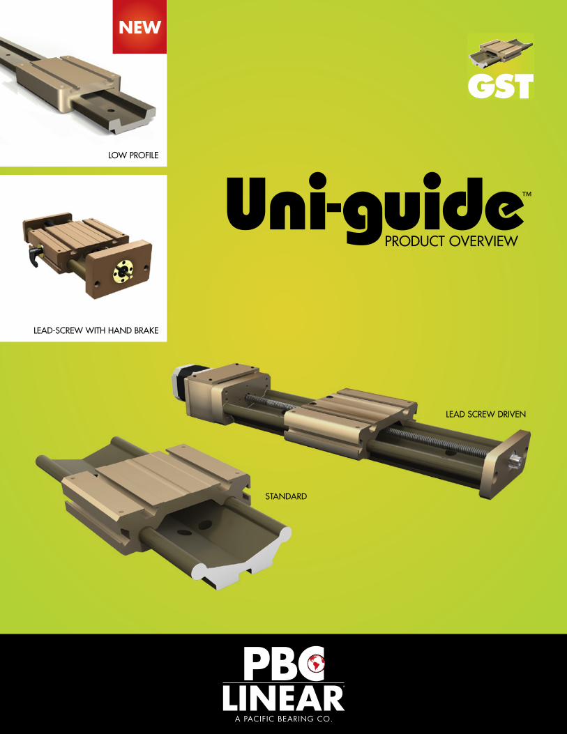
™
PRODUCT OVERVIEW
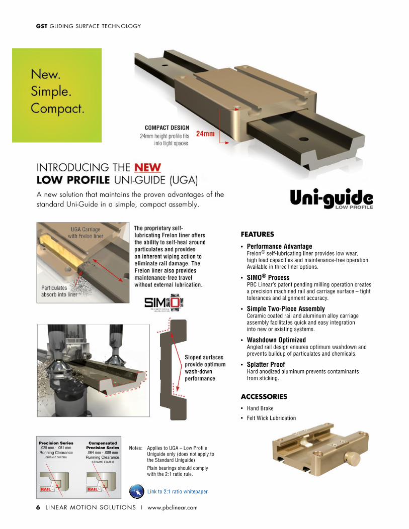
NEW
LOW PROFILE
LEAD SCREW DRIVEN
STANDARD
LEAD-SCREW WITH HAND BRAKE
2 L INEAR MOTION SOLUTIONS I www.pbclinear.com
GST GLIDING SURFACE TECHNOLOGY
www.pbclinear.com I L INEAR MOTION SOLUTIONS 3
GLIDING SURFACE TECHNOLOGY GST
F
Fy
F
CL of Mz CL of Mx CL of My
F
Fy
MxMy
F
F
Mz
CL of Mz
Mz
F
Fy
F
CL of Mz CL of Mx CL of My
F
Fy
MxMy
F
F
Mz
CL of Mz
Mz
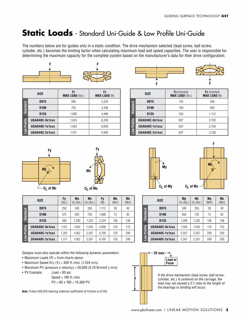
The numbers below are for guides only in a static condition. The drive mechanism selected (lead screw, ball screw, cylinder, etc.) becomes the limiting factor when calculating maximum load and speed capacities. The user is responsible for determining the maximum capacity for the complete system based on the manufacturer’s data for their drive configuration.
2X max.
X
Load or Force
If the drive mechanism (lead screw, ball screw, cylinder, etc.) is centered on the carriage, the load may not exceed a 2:1 ratio to the length of the bearings or binding will occur.
Designs must also operate within the following dynamic parameters:• Maximum Loads (P) = from charts above• Maximum Speed Dry (V) = 300 ft./min. (1.524 m/s)• Maximum PV (pressure x velocity) = 20,000 (0.70 N/mm2 x m/s)• PV Example: Load = 85 psi Speed = 180 ft./min. PV = 85 x 180 = 15,300 PV
Note: Frelon GOLD® bearing material coefficient of friction is 0.125.
SIZE FzMAX LOAD (lbs.)
FzMAX LOAD (N)
Stan
dard D075 500 2,224
D100 750 3,336
D125 1,000 4,448
Low
Pro
file UGA040C-0x1xxx 1,843 8,200
UGA040C-1x1xxx 1,483 6,600
UGA040C-2x1xxx 1,101 4,900
SIZE Fy (lbs.)
Mx (in./lbs.)
Mz (in./lbs.)
Fy (N)
Mx (Nm)
Mz (Nm)
Stan
dard D075 250 340 350 1,112 38 40
D100 375 650 730 1,668 73 82
D125 500 1,200 1,225 2,224 136 138
Low
Pro
file UGA040C-0x1xxx 1,101 1,062 1,505 4,900 120 170
UGA040C-1x1xxx 1,281 1,062 2,567 5,700 120 290
UGA040C-2x1xxx 1,371 1,062 2,567 6,100 120 290
SIZE My (in./lbs.)
Mz (in./lbs.)
My (Nm)
Mz (Nm)
Stan
dard D075 340 350 38 40
D100 650 730 73 82
D125 1,200 1,225 136 138
Low
Pro
file UGA040C-0x1xxx 1,505 1,505 170 170
UGA040C-1x1xxx 2,567 2,567 290 290
UGA040C-2x1xxx 2,567 2,567 290 290
SIZE Fz (Inverted)MAX LOAD (lbs.)
Fz (Inverted)MAX LOAD (N)
Stan
dard D075 125 556
D100 190 845
D125 250 1,112
Low
Pro
file UGA040C-0x1xxx 607 2,700
UGA040C-1x1xxx 607 2,700
UGA040C-2x1xxx 607 2,700
Static Loads - Standard Uni-Guide & Low Profile Uni-Guide
4 L INEAR MOTION SOLUTIONS I www.pbclinear.com
GST GLIDING SURFACE TECHNOLOGY
CRM
LC1
XYC4
R4
C2
H
C3
M1
R1T2
T1T
R2
CRM
LC1
XYC4
R4
C2
H
C3
M1
R1T2
T1T
R2
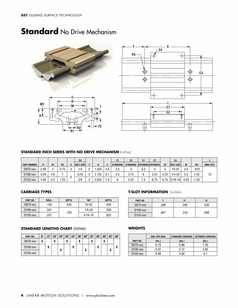
PART NUMBER R R1 R2 X
R4
Y H C
C1 C2 C1 C2
C3
C4
M M1
L
BOLT SIZE STANDARD STANDARD EXTENDED EXTENDED BOLT SIZE MAX-FEET
D075-xxx 2.95 2 0.75 4 1/4 2 1.625 4.6 3.5 3 4.5 4 4 10-32 2.6 .819
12D100-xxx 3.94 2.6 16
5/16 3 2.125 6.1 4.5 3.75 6 5.25 5.25 1/4-20 3.5 1.02
D125-xxx 4.92 3.3 1.25 3/8 3 2.625 7.6 6 5.25 7.5 6.75 6.75 5/16-18 4.33 1.30
STANDARD INCH SERIES WITH NO DRIVE MECHANISM (inches)
PART NO. T T1 T2
D075-xxx .590 .256 .236
D100-xxx.661 .319 .268
D125-xxx
T-SLOT INFORMATION (inches)
PART NO. 8" 12" 16" 18" 20" 24" 28" 30" 32" 36" 40" 42" 48"
D075-xxx X
X
X X
X
X X
X
X
XD100-xxxX X X
D125-xxx
STANDARD LENGTHS CHART (inches)
PART NO. DRILL DEPTH TAP DEPTH
D075-xxx .159 .534 10-32 .440
D100-xxx .201.750
1/4-20 .500
D125-xxx .257 5/16-18 .625
CARRIAGE TYPES
PART NO.
RAIL PER INCH STANDARD CARRIAGE EXTENDED CARRIAGE
(lbs.) (lbs.) (lbs.)
D075-xxx 0.19 0.98 1.26D100-xxx 0.32 2.12 2.82D125-xxx 0.48 4.56 5.7
WEIGHTS
Standard No Drive Mechanism
www.pbclinear.com I L INEAR MOTION SOLUTIONS 5
GLIDING SURFACE TECHNOLOGY GST
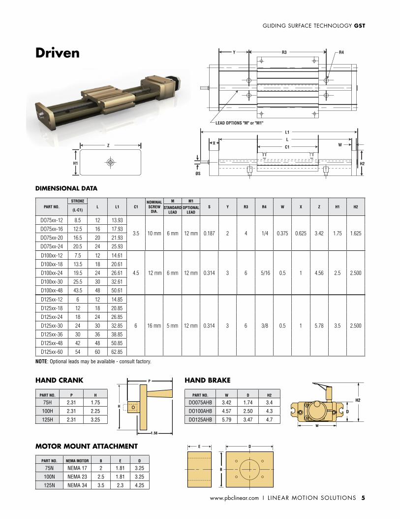
DIMENSIONAL DATA
Driven
DE
B
H
1.56
P
PART NO. NEMA MOTOR B E D
75N NEMA 17 2 1.81 3.25
100N NEMA 23 2.5 1.81 3.25
125N NEMA 34 3.5 2.3 4.25
PART NO. P H
75H 2.31 1.75
100H 2.31 2.25
125H 2.31 3.25
HAND CRANK
PART NO. W D H2
DO075AHB 3.42 1.74 3.4
DO100AHB 4.57 2.50 4.3
DO125AHB 5.79 3.47 4.7w
D
H2
HAND BRAKE
MOTOR MOUNT ATTACHMENT
PART NO.STROKE
L L1 C1NOMINAL SCREW
DIA.
M M1S Y R3 R4 W X Z H1 H2
(L-C1) STANDARD LEAD
OPTIONAL LEAD
DO75xx-12 8.5 12 13.93
3.5 10 mm 6 mm 12 mm 0.187 2 4 1/4 0.375 0.625 3.42 1.75 1.625DO75xx-16 12.5 16 17.93
DO75xx-20 16.5 20 21.93
DO75xx-24 20.5 24 25.93
D100xx-12 7.5 12 14.61
4.5 12 mm 6 mm 12 mm 0.314 3 6 5/16 0.5 1 4.56 2.5 2.500
D100xx-18 13.5 18 20.61
D100xx-24 19.5 24 26.61
D100x x-30 25.5 30 32.61
D100x x-48 43.5 48 50.61
D125xx-12 6 12 14.85
6 16 mm 5 mm 12 mm 0.314 3 6 3/8 0.5 1 5.78 3.5 2.500
D125xx-18 12 18 20.85
D125xx-24 18 24 26.85
D125xx-30 24 30 32.85
D125xx-36 30 36 38.85
D125xx-48 42 48 50.85
D125xx-60 54 60 62.85
LEAD OPTIONS "M" or "M1"
R3 R4Y
C1Z WL
X
ØS
L1
H2H1
NOTE: Optional leads may be available - consult factory.
6 L INEAR MOTION SOLUTIONS I www.pbclinear.com
GST GLIDING SURFACE TECHNOLOGY
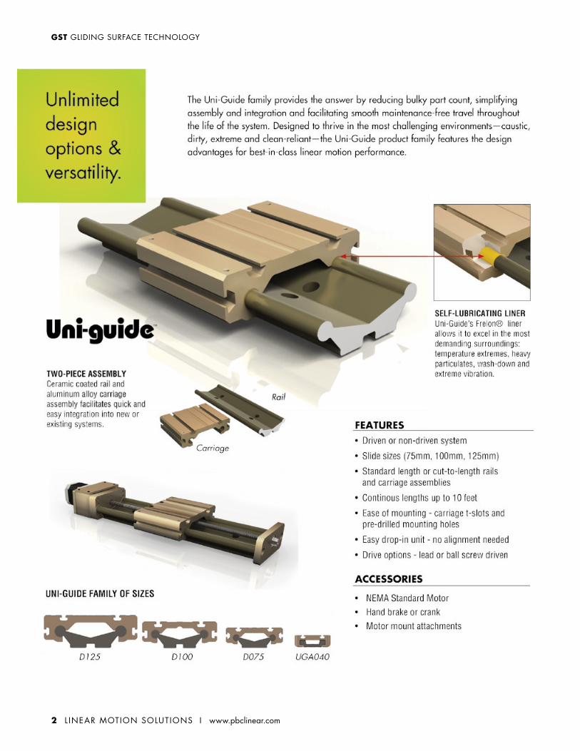
FEATURES
ACCESSORIES
.025 mm - .051 mm.064 mm - .089 mm
Notes: Applies to UGA – Low Profile Uniguide only (does not apply to the Standard Uniguide)
Plain bearings should comply with the 2:1 ratio rule.
Link to 2:1 ratio whitepaper
• Performance Advantage Frelon® self-lubricating liner provides low wear, high load capacities and maintenance-free operation. Available in three liner options.
• SIMO® Process PBC Linear’s patent pending milling operation creates a precision machined rail and carriage surface – tight tolerances and alignment accuracy.
• Simple Two-Piece Assembly Ceramic coated rail and aluminum alloy carriage assembly facilitates quick and easy integration into new or existing systems.
• Washdown Optimized Angled rail design ensures optimum washdown and prevents buildup of particulates and chemicals.
• Splatter Proof Hard anodized aluminum prevents contaminants from sticking.
• Hand Brake
• Felt Wick Lubrication
www.pbclinear.com I L INEAR MOTION SOLUTIONS 7
GLIDING SURFACE TECHNOLOGY GST
73.040.0
5.924.0
52.0 37.1
SIZE 5 T-SLOT
C2C4 C4
C3
C1
60.0 TYP20.0
6.6 TYP
C2
C1
STANDARD CARRIAGE EXTENDED CARRIAGE
1 2
10.5
2.85.5 THRU
M6X1.0 - 6H 13.0
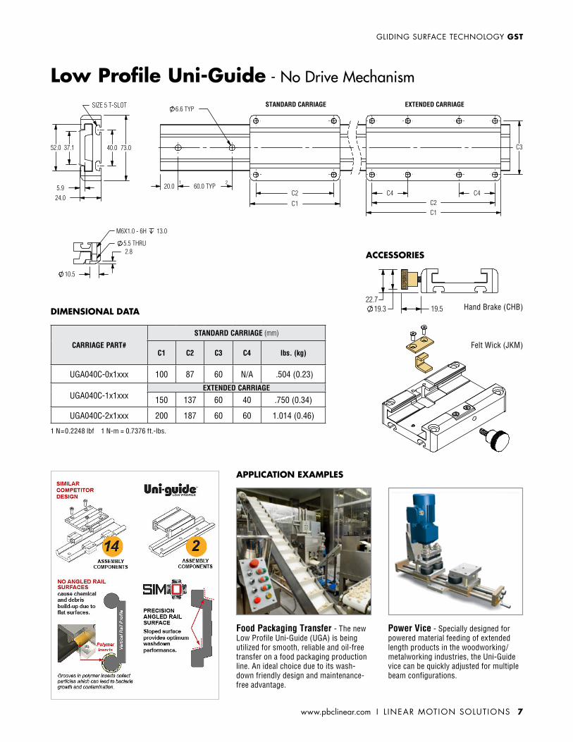
CARRIAGE PART#
STANDARD CARRIAGE (mm)
C1 C2 C3 C4 lbs. (kg)
UGA040C-0x1xxx 100 87 60 N/A .504 (0.23)
UGA040C-1x1xxxEXTENDED CARRIAGE
150 137 60 40 .750 (0.34)
UGA040C-2x1xxx 200 187 60 60 1.014 (0.46)
1 N=0.2248 lbf 1 N-m = 0.7376 ft.-lbs.
DIMENSIONAL DATA
APPLICATION EXAMPLES
ACCESSORIES
Low Profile Uni-Guide - No Drive Mechanism
Food Packaging Transfer - The new Low Profile Uni-Guide (UGA) is being utilized for smooth, reliable and oil-free transfer on a food packaging production line. An ideal choice due to its wash-down friendly design and maintenance-free advantage.
Power Vice - Specially designed for powered material feeding of extended length products in the woodworking/metalworking industries, the Uni-Guide vice can be quickly adjusted for multiple beam configurations.
19.522.7
19.3 Hand Brake (CHB)
Felt Wick (JKM)
8 L INEAR MOTION SOLUTIONS I www.pbclinear.com
GST GLIDING SURFACE TECHNOLOGY
Product information and 2D/3D CAD drawings available for download at www.pbclinear.comFor technical information or to order call 1-800-962-8979© 2013 PBC Linear®, A Pacific Bearing Company • “PBC Linear” and “PBC Lineartechnik GmbH” are subsidiaries of Pacific Bearing Company (“PBC”). The data and specifications in this publication have been carefully compiled and are believed to be accurate and correct. It is the responsibility of the user to determine and ensure the suitability of PBC’s products for a specific application. PBC’s only obligation will be to repair or replace, without charge, any defective components if returned promptly. No liability is assumed beyond such replacement. Specifications and dimensions are subject to change without notice. Other corporate and product names, images, text and logos may be trademarks or copyrights of other companies and are used only for explanation and to the owners benefit; without intent to infringe. This document may not be reproduced, in part or whole, without the prior written authorization of PBC. Consult www.pbclinear.com for the latest technical updates. LITGST-008 [r12-13]
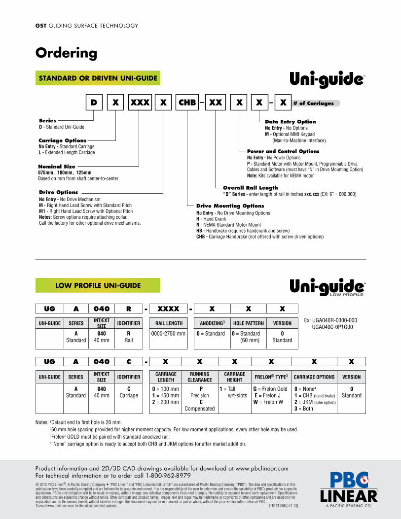
D X XXX X CHB XX X X
Carriage OptionsNo Entry - Standard CarriageL - Extended Length Carriage
Nominal Size075mm, 100mm, 125mmBased on mm from shaft center-to-center
Drive Mounting OptionsNo Entry - No Drive Mounting OptionsH - Hand CrankN - NEMA Standard Motor MountHB - Handbrake (requires handcrank and screw)CHB - Carriage Handbrake (not offered with screw driven options)
Drive OptionsNo Entry - No Drive MechanismM - Right Hand Lead Screw with Standard PitchM1 - Right Hand Lead Screw with Optional Pitch Notes: Screw options require attaching collar.Call the factory for other optional drive mechanisms.
Data Entry OptionNo Entry - No OptionsM - Optional MMI Keypad (Man-to-Machine Interface)
X # of Carriages
Overall Rail Length“D” Series - enter length of rail in inches xxx.xxx (EX: 6” = 006.000)
Power and Control OptionsNo Entry - No Power OptionsP - Standard Motor with Motor Mount, Programmable Drive, Cables and Software (must have “N” in Drive Mounting Option)Note: Kits available for NEMA motor
– –
SeriesD - Standard Uni-Guide
UG A 040 C - X X X X X X
UNI-GUIDE SERIES INT/EXT SIZE IDENTIFIER CARRIAGE
LENGTHRUNNING
CLEARANCECARRIAGE
HEIGHT FRELON® TYPE3 CARRIAGE OPTIONS VERSION
A Standard
040 40 mm
C Carriage
0 = 100 mm1 = 150 mm 2 = 200 mm
P Precision
C Compensated
1 = Tall w/t-slots
G = Frelon Gold E = Frelon J W = Frelon W
0 = None4
1 = CHB (hand brake) 2 = JKM (lube option) 3 = Both
0 Standard
UG A 040 R - XXXX - X X X
UNI-GUIDE SERIES INT/EXT SIZE IDENTIFIER RAIL LENGTH ANODIZING3 HOLE PATTERN VERSION
A Standard
040 40 mm
R Rail
0000-2750 mm 0 = Standard
0 = Standard (60 mm)
0 Standard
Notes: 1Default end to first hole is 20 mm 260 mm hole spacing provided for higher moment capacity. For low moment applications, every other hole may be used. 3Frelon® GOLD must be paired with standard anodized rail. 4”None” carriage option is ready to accept both CHB and JKM options for after market addition.
Ex: UGA040R-0300-000 UGA040C-0P1G00
STANDARD OR DRIVEN UNI-GUIDE
LOW PROFILE UNI-GUIDE
Ordering™