Embed Size (px)
Citation preview

HopkinsonsINDEX
2 Weir Valves & Controls First choice for process protection WVC-HOP001-R0
Weir Valves & Controls 4
The Hopkinson Story 6 - 17
Company Milestones 18
Boiler Mountings & Valves 18
Parallel Slide Gate Valves(a) Operating & Design Features 19 - 20(b) Product Application 20(c) Hopkinsons Product Range & Features 20(d) Valve Construction 20
(i) Back Seating(ii) Packing Under Pressure(iii) Seats & Discs
(e) Comparison of Parallel Slide Valve with Wedge Gate 22 - 25(i) Seating Principles(ii) Thermal Binding(iii) Ease of Maintenance
(f) Optional End Connections 26(g) Bolted Bonnets 26(h) Stuffing Box Design 26 - 28
(i) Exfoliated Graphite Packing(ii) Upgrading of Conventional Glands & Pressure Seal Bonnets(iii) Water Sealed Glands
(i) High pressure Parallel Slide Gate Valves 28 - 33(i) Pressure Seal Bonnets(ii) Venturi Bore Design(iii) Follower Eye(iv) Seat Velocities(v) Product Ratings(vi) Relationship Between Nom. Pipe Size & Valve Seat Diameter (vii) Vee Port Outlet Seats(viii)Steam Purging with Venturi Valve Design(ix) Process, Petrochemical & Nuclear Market
Bypass Valves(a) Application 33(b) Method of Operating 34
Equalising Bypass Valves & Devices(a) Hydraulic Lock 35(b) Balanced Spindle Valves 35 - 36(c) Equalising Pipes & Applications 36(d) Over Pressure 36 - 37(e) Alternative Equalising Devices 37(f) Equalising Bypass 37 - 38
Types of Main Valve Operation 38 - 42
Check & Non-Return Valves(a) Swing Check Valves 43(b) Low & High Pressure Variants 44(c) Feedwater Check Valves 44(d) Vertical Lift Check Valves 45(e) Comparitive Disc Movements (Vertical Lift & Swing Check) 45(f) Stop Check Valves (Stop & Non-Return Valves) 45(g) Tilting Disc Check Valves 46 - 47(h) Bled Steam (Extraction Steam) Non-Return Valves 48 - 53
(i) Features of Hopkinson Design(ii) Valve Application(iii) Competition
3Weir Valves & Controls First choice for process protection
Hopkinsons INDEX
WVC-HOP001-R0
Reheater Isolation Devices 53 - 56
Drain & Blowdown Valves(a) Comparison of Types 56 - 58
(i) Wedge Gate Valve(ii) Globe Valve(iii) Ball Valve(iv) Parallel Slide Gate Valve
(b) Rack & Pinion Blowdown Valves 58 - 59(c) Uniflow Drain Valves 59(d) High Performance Parallel Slide Gate Valves 60
Water Gauges (Water Level Indicators)(a) ‘Absolute’ Type 60 - 61(b) Plate Glass Type 61(c) ‘Bulls Eye’ Type 62(d) Try Valves 62
ASME Section 1 Safety Valves(a) Definition of Safety Valve Types & Terms 63
(i) Safety Valve(ii) Relief valve(iii) Safety Relief Valve(iv) Set Pressure(v) Simmer(vi) Lift(vii) Rated Capacity(viii)Accumulation(ix) Overpressure(x) Blowdown
(b) Hopkinsons Product Range & Ratings 64 - 66(i) Features & Benefits(ii) Principal Competitors
(c) Hopkinsons Steam Test Facility 67(d) Safety Valve Mounting 67(e) Hydrostatic Testing 68 - 69
(i) Hopkinsons Products(ii) Competitors
(f) Servo Loaded Direct Acting Safety Valves 69(g) Anti Simmer Devices 69 - 70
Feed Water Heaters 71
Feed Water Heater Bypass Systems(a) Electrically Operated Gate Valves 72(b) Spring Loaded Bypass Valves 72 - 73(c) Competitors 73(d) Atwood & Morrill 3-Way Valves 73 - 74(e) Medium operated 2-Way Changeover Valves 75
Combined Cycle Power Plant System
Fossil Fuel Power Plant System
4 Weir Valves & Controls First choice for process protection WVC-HOP001-R0
HopkinsonsPRODUCT SUPPORT MANUAL
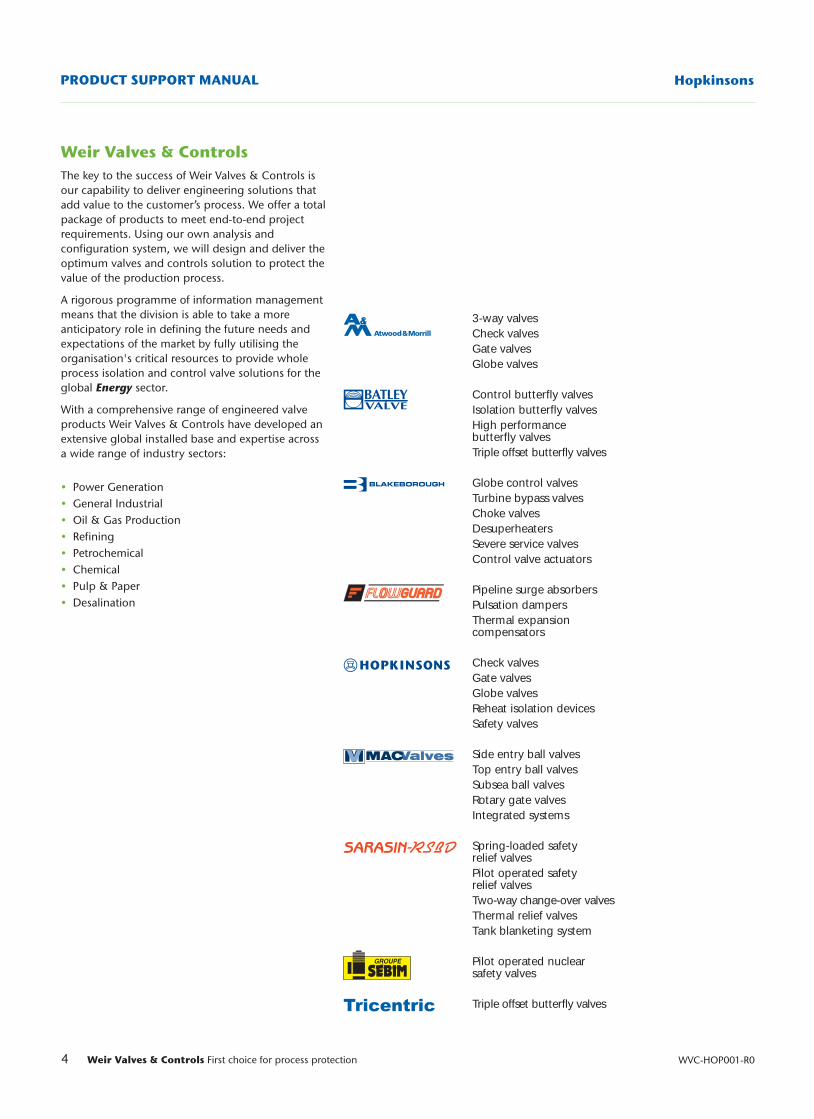
3-way valvesCheck valvesGate valvesGlobe valves
Control butterfly valvesIsolation butterfly valvesHigh performancebutterfly valvesTriple offset butterfly valves
Globe control valvesTurbine bypass valvesChoke valvesDesuperheatersSevere service valvesControl valve actuators
Pipeline surge absorbersPulsation dampersThermal expansioncompensators
Check valvesGate valvesGlobe valvesReheat isolation devicesSafety valves
Side entry ball valvesTop entry ball valvesSubsea ball valvesRotary gate valvesIntegrated systems
Spring-loaded safetyrelief valvesPilot operated safetyrelief valvesTwo-way change-over valvesThermal relief valvesTank blanketing system
Pilot operated nuclearsafety valves
Triple offset butterfly valves
Weir Valves & Controls The key to the success of Weir Valves & Controls isour capability to deliver engineering solutions thatadd value to the customer’s process. We offer a totalpackage of products to meet end-to-end projectrequirements. Using our own analysis andconfiguration system, we will design and deliver theoptimum valves and controls solution to protect thevalue of the production process.
A rigorous programme of information managementmeans that the division is able to take a moreanticipatory role in defining the future needs andexpectations of the market by fully utilising theorganisation's critical resources to provide wholeprocess isolation and control valve solutions for theglobal Energy sector.
With a comprehensive range of engineered valveproducts Weir Valves & Controls have developed anextensive global installed base and expertise acrossa wide range of industry sectors:
• Power Generation• General Industrial• Oil & Gas Production• Refining• Petrochemical• Chemical• Pulp & Paper• Desalination
5Weir Valves & Controls First choice for process protection
Hopkinsons PRODUCT SUPPORT MANUAL
WVC-HOP001-R0
Quality assuranceWeir Valves & Controls operates qualityprogrammes to cover the full scope of theiractivities. Comprehensive quality systems havebeen developed to serve the power, oil and gas andindustrial markets which they serve.
The company holds approvals to:
• ASME Section III ‘N’, ‘NPT’, ‘NV’
• ASME Section I ‘V’
• ASME Section VIII code UV
• BS EN ISO 9001:1994
• NF EN ISO 9001
• API Q1 TO API LICENCES API 6D (6D-0182) and API 6A (6A-0445)
• API 526
• TUV - AD MERKBLATT WRD HP 0
The Quality systems have been approved for thesupply of products to meet the requirements of thePressure Equipment Directive (PED) andcompliance modules A,D1,H,B&D have beenapplied in categories I through IV respectively.
The company is committed to compliance withlegislation and has an established environment andhealth and safety policy.
An ongoing commitment to customer care is metthrough the process of continuous improvementand the further development of our systems andprocesses towards meeting ISO 9001:2000.
Valve testing facilitiesAll pressure containing items are hydrostaticallytested, seat leakage tested and functionally tested.In addition, gas, packing emission, cryogenic andadvanced functional testing can be arranged.
Material testing facilities• Non-destructive examination by radiography,
ultrasonics, magnetic particle and liquid penetrant.
• Chemical analysis by computer controlled directreading emission spectrometer.
• Mechanical testing for tensile properties at ambientand elevated temperatures, bend and hardnesstesting. Charpy testing at ambient, elevated andsub-zero temperatures.
Further technical information can be obtained fromour Web site: http://www.weirvalve.com
HopkinsonsWeir Valves and Controls manufacture HopkinsonsValves and Boiler Mountings for use on steamraising plant of any size and type.
Hopkinsons brand products, renowned for longand dependable service life, can be seen oninstallations ranging from shell boilers for heatingand process steam up to the highest capacity unitson electricity generating stations.
In the nuclear power industry, the Hopkinsonname is synonymous with expertise in the designand production of safety related items such as fastoperating main steam and main feed isolationvalves.
The Hopkinson range of products also includesvalves for isolation, regulation, pressure relief,instrumentation and drain and specific plantprotection duties on the new generation ofCombined Cycle Gas Turbine Power Stations.
6A-04456D-0182
6 Weir Valves & Controls First choice for process protection WVC-HOP001-R0
HopkinsonsTHE HOPKINSON STORY
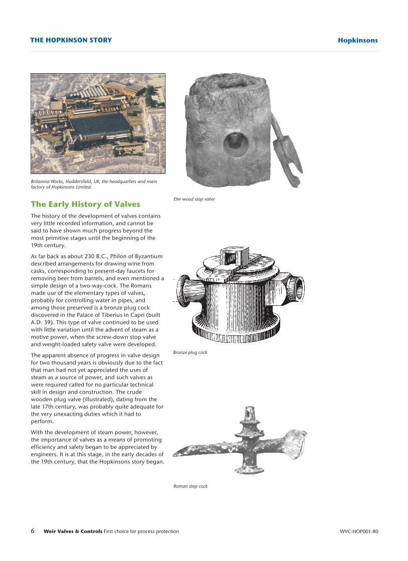
Britannia Works, Huddersfield, UK, the headquarters and mainfactory of Hopkinsons Limited.
The Early History of ValvesThe history of the development of valves containsvery little recorded information, and cannot besaid to have shown much progress beyond themost primitive stages until the beginning of the19th century.
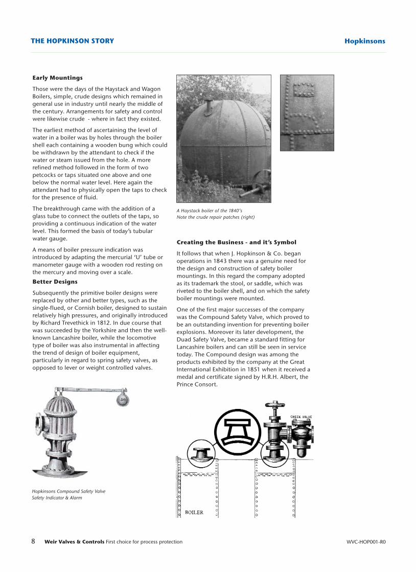
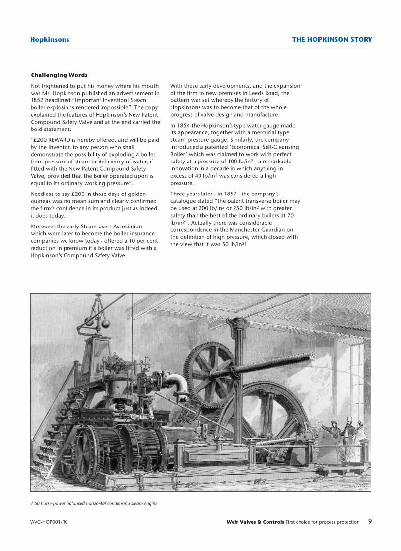
As far back as about 230 B.C., Philon of Byzantiumdescribed arrangements for drawing wine fromcasks, corresponding to present-day faucets forremoving beer from barrels, and even mentioned asimple design of a two-way-cock. The Romansmade use of the elementary types of valves,probably for controlling water in pipes, andamong those preserved is a bronze plug cockdiscovered in the Palace of Tiberius in Capri (builtA.D. 39). This type of valve continued to be usedwith little variation until the advent of steam as amotive power, when the screw-down stop valveand weight-loaded safety valve were developed.
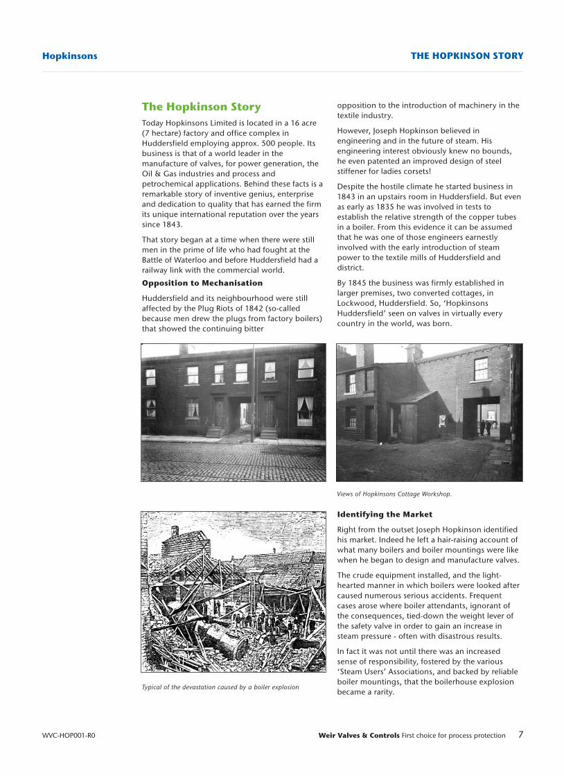
The apparent absence of progress in valve designfor two thousand years is obviously due to the factthat man had not yet appreciated the uses ofsteam as a source of power, and such valves aswere required called for no particular technicalskill in design and construction. The crudewooden plug valve (illustrated), dating from thelate 17th century, was probably quite adequate forthe very unexacting duties which it had toperform.
With the development of steam power, however,the importance of valves as a means of promotingefficiency and safety began to be appreciated byengineers. It is at this stage, in the early decades ofthe 19th century, that the Hopkinsons story began.
Elm wood stop valve
Bronze plug cock
Roman stop cock
opposition to the introduction of machinery in thetextile industry.
However, Joseph Hopkinson believed inengineering and in the future of steam. Hisengineering interest obviously knew no bounds,he even patented an improved design of steelstiffener for ladies corsets!
Despite the hostile climate he started business in1843 in an upstairs room in Huddersfield. But evenas early as 1835 he was involved in tests toestablish the relative strength of the copper tubesin a boiler. From this evidence it can be assumedthat he was one of those engineers earnestlyinvolved with the early introduction of steampower to the textile mills of Huddersfield anddistrict.
By 1845 the business was firmly established inlarger premises, two converted cottages, inLockwood, Huddersfield. So, ‘HopkinsonsHuddersfield’ seen on valves in virtually everycountry in the world, was born.
Identifying the Market
Right from the outset Joseph Hopkinson identifiedhis market. Indeed he left a hair-raising account ofwhat many boilers and boiler mountings were likewhen he began to design and manufacture valves.
The crude equipment installed, and the light-hearted manner in which boilers were looked aftercaused numerous serious accidents. Frequentcases arose where boiler attendants, ignorant ofthe consequences, tied-down the weight lever ofthe safety valve in order to gain an increase insteam pressure - often with disastrous results.
In fact it was not until there was an increasedsense of responsibility, fostered by the various‘Steam Users’ Associations, and backed by reliableboiler mountings, that the boilerhouse explosionbecame a rarity.
7Weir Valves & Controls First choice for process protection
Hopkinsons THE HOPKINSON STORY
WVC-HOP001-R0
Views of Hopkinsons Cottage Workshop.
Typical of the devastation caused by a boiler explosion
The Hopkinson StoryToday Hopkinsons Limited is located in a 16 acre(7 hectare) factory and office complex inHuddersfield employing approx. 500 people. Itsbusiness is that of a world leader in themanufacture of valves, for power generation, theOil & Gas industries and process andpetrochemical applications. Behind these facts is aremarkable story of inventive genius, enterpriseand dedication to quality that has earned the firmits unique international reputation over the yearssince 1843.
That story began at a time when there were stillmen in the prime of life who had fought at theBattle of Waterloo and before Huddersfield had arailway link with the commercial world.
Opposition to Mechanisation
Huddersfield and its neighbourhood were stillaffected by the Plug Riots of 1842 (so-calledbecause men drew the plugs from factory boilers)that showed the continuing bitter
8 Weir Valves & Controls First choice for process protection WVC-HOP001-R0
HopkinsonsTHE HOPKINSON STORY
A Haystack boiler of the 1840’sNote the crude repair patches (right)
Hopkinsons Compound Safety ValveSafety Indicator & Alarm
Early Mountings
Those were the days of the Haystack and WagonBoilers, simple, crude designs which remained ingeneral use in industry until nearly the middle ofthe century. Arrangements for safety and controlwere likewise crude - where in fact they existed.
The earliest method of ascertaining the level ofwater in a boiler was by holes through the boilershell each containing a wooden bung which couldbe withdrawn by the attendant to check if thewater or steam issued from the hole. A morerefined method followed in the form of twopetcocks or taps situated one above and onebelow the normal water level. Here again theattendant had to physically open the taps to checkfor the presence of fluid.
The breakthrough came with the addition of aglass tube to connect the outlets of the taps, soproviding a continuous indication of the waterlevel. This formed the basis of today’s tubularwater gauge.
A means of boiler pressure indication wasintroduced by adapting the mercurial ‘U’ tube ormanometer gauge with a wooden rod resting onthe mercury and moving over a scale.
Better Designs
Subsequently the primitive boiler designs werereplaced by other and better types, such as thesingle-flued, or Cornish boiler, designed to sustainrelatively high pressures, and originally introducedby Richard Trevethick in 1812. In due course thatwas succeeded by the Yorkshire and then the well-known Lancashire boiler, while the locomotivetype of boiler was also instrumental in affectingthe trend of design of boiler equipment,particularly in regard to spring safety valves, asopposed to lever or weight controlled valves.
Creating the Business - and it’s Symbol
It follows that when J. Hopkinson & Co. beganoperations in 1843 there was a genuine need forthe design and construction of safety boilermountings. In this regard the company adoptedas its trademark the stool, or saddle, which wasriveted to the boiler shell, and on which the safetyboiler mountings were mounted.
One of the first major successes of the companywas the Compound Safety Valve, which proved tobe an outstanding invention for preventing boilerexplosions. Moreover its later development, theDuad Safety Valve, became a standard fitting forLancashire boilers and can still be seen in servicetoday. The Compound design was among theproducts exhibited by the company at the GreatInternational Exhibition in 1851 when it received amedal and certificate signed by H.R.H. Albert, thePrince Consort.
9Weir Valves & Controls First choice for process protection
Hopkinsons THE HOPKINSON STORY
WVC-HOP001-R0
A 60 horse-power balanced horizontal condensing steam engine
Challenging Words
Not frightened to put his money where his mouthwas Mr. Hopkinson published an advertisement in1852 headlined “Important Invention! Steamboiler explosions rendered impossible”. The copyexplained the features of Hopkinson’s New PatentCompound Safety Valve and at the end carried thebold statement:
“£200 REWARD is hereby offered, and will be paidby the Inventor, to any person who shalldemonstrate the possibility of exploding a boilerfrom pressure of steam or deficiency of water, iffitted with the New Patent Compound SafetyValve, provided that the Boiler operated upon isequal to its ordinary working pressure”.
Needless to say £200 in those days of goldenguineas was no mean sum and clearly confirmedthe firm’s confidence in its product just as indeedit does today.
Moreover the early Steam Users Association -which were later to become the boiler insurancecompanies we know today - offered a 10 per centreduction in premium if a boiler was fitted with aHopkinson’s Compound Safety Valve.
With these early developments, and the expansionof the firm to new premises in Leeds Road, thepattern was set whereby the history ofHopkinsons was to become that of the wholeprogress of valve design and manufacture.
In 1854 the Hopkinson’s type water gauge madeits appearance, together with a mercurial typesteam pressure gauge. Similarly, the companyintroduced a patented ‘Economical Self-CleansingBoiler’ which was claimed to work with perfectsafety at a pressure of 100 Ib/in2 - a remarkableinnovation in a decade in which anything inexcess of 40 Ib/in2 was considered a highpressure.
Three years later - in 1857 - the company’scatalogue stated “the patent transverse boiler maybe used at 200 Ib/in2 or 250 Ib/in2 with greatersafety than the best of the ordinary boilers at 70Ib/in2”. Actually there was considerablecorrespondence in the Manchester Guardian onthe definition of high pressure, which closed withthe view that it was 50 Ib/in2!
10 Weir Valves & Controls First choice for process protection WVC-HOP001-R0
HopkinsonsTHE HOPKINSON STORY
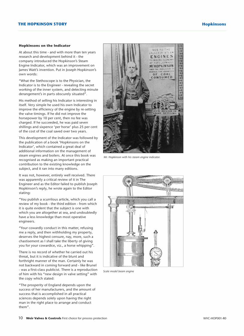
Mr. Hopkinson with his steam engine indicator.
Scale model beam engine
Hopkinsons on the Indicator
At about this time - and with more than ten yearsresearch and development behind it - thecompany introduced the Hopkinson’s SteamEngine Indicator, which was an improvement onJames Watt’s invention. Put in Joseph Hopkinson’sown words:
“What the Stethoscope is to the Physician, theIndicator is to the Engineer - revealing the secretworking of the inner system, and detecting minutederangement’s in parts obscurely situated”.
His method of selling his Indicator is interesting initself. Very simple he used his own Indicator toimprove the efficiency of the engine by re-settingthe valve timings. If he did not improve thehorsepower by 10 per cent, then no fee wascharged. If he succeeded, he was paid sevenshillings and sixpence ‘per horse’ plus 25 per centof the cost of the coal saved over two years.
This development of the Indicator was followed bythe publication of a book ‘Hopkinsons on theIndicator’, which contained a great deal ofadditional information on the management ofsteam engines and boilers. At once this book wasrecognised as making an important practicalcontribution to the existing knowledge on thesubject, and it ran into many editions.
It was not, however, entirely well received. Therewas apparently a critical review of it in TheEngineer and as the Editor failed to publish JosephHopkinson’s reply, he wrote again to the Editorstating:
“You publish a scurrilous article, which you call areview of my book - the third edition - from whichit is quite evident that the subject is one withwhich you are altogether at sea, and undoubtedlyhave a less knowledge than most operativeengineers.
“Your cowardly conduct in this matter, refusingme a reply, and then withholding my property,deserves the highest censure, nay, more, such achastisement as I shall take the liberty of givingyou for your cowardice, viz., a horse whipping”.
There is no record of whether he carried out histhreat, but it is indicative of the blunt andforthright manner of the man. Certainly he wasnot backward in coming forward and - like Brunel- was a first-class publicist. There is a reproductionof him with his “new design in valve setting” withthe copy which stated:
“The prosperity of England depends upon thesuccess of her manufacturers, and the amount ofsuccess that is accomplished in all practicalsciences depends solely upon having the rightman in the right place to arrange and conductthem”.
11Weir Valves & Controls First choice for process protection
Hopkinsons THE HOPKINSON STORY
WVC-HOP001-R0
Taking to the Waves
The earliest mention of Hopkinsons involvement inmarine engineering appears at this time in the 2ndedition of ‘Hopkinsons on the Indicator’ dated1857. Joseph Hopkinson gives an account of testsusing his Indicator instrument on the engines ofthe S.S. Great Britain, the first ocean going ship tobe built of iron and to have screw propulsion.Hopkinson gives an account of some length inwhich he firstly proves the inefficiency of theoriginal engines, then goes on to show howmodifications to the engines resulted in increasingthe total output from 686 to 1,663 horse power.Holding nothing back he severely raps theknuckles of the original engine constructor forperpetrating ‘such a glaring blunder as he didcommit in turning out such inefficient machines’.
From that day on the name of Hopkinsons was tobe associated with the best of British Shipbuilding.Through the years of the great ocean goingpassenger vessels - to the latest and probably thelast - the Queen Elizabeth 2. The Royal Yacht‘Britannia’ was also fitted with Hopkinson’s valves.
With the Royal Navy too, the company has a longreputation for technical expertise and productreliability. Standard and special purpose valveshave been supplied for a variety of ships from theaircraft carriers and battleships of the SecondWorld War to the smaller frigates and nuclearpowered submarines of today.
Indeed it was from the company’s experience indesigning and supplying rapid operatingemergency closing parallel slide valves - astandard requirement on all RN steam driven shipssince the 1930’s - that has enabled Hopkinsons togain substantial orders over recent years for quickclosing steam and feedwater isolation valves onnuclear power stations worldwide.
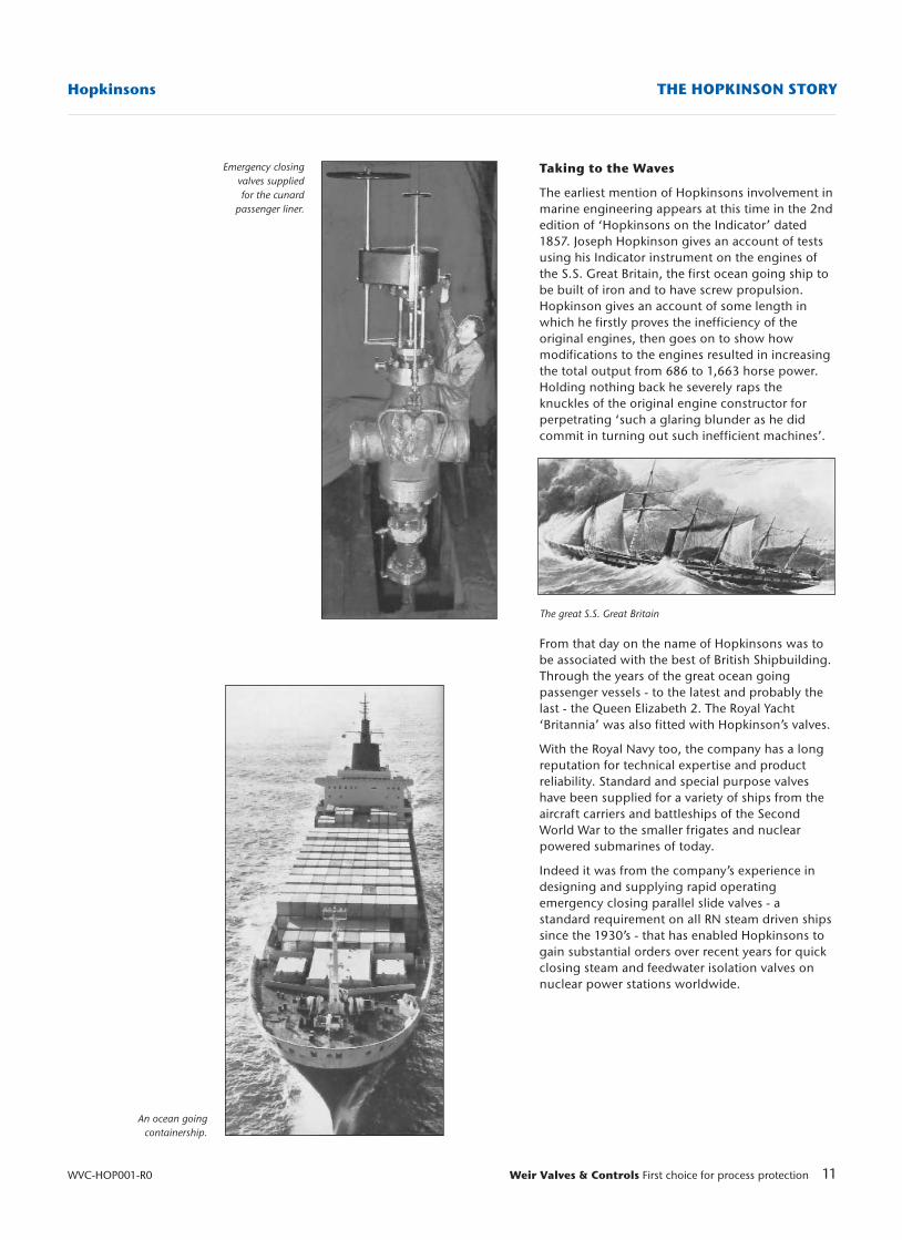
Emergency closingvalves suppliedfor the cunard
passenger liner.
An ocean going containership.
The great S.S. Great Britain
12 Weir Valves & Controls First choice for process protection WVC-HOP001-R0
HopkinsonsTHE HOPKINSON STORY
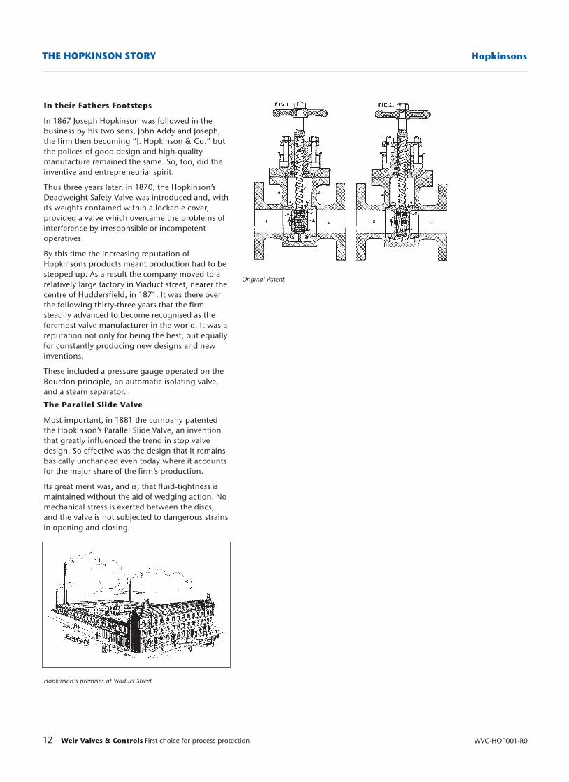
Original Patent
Hopkinson’s premises at Viaduct Street
In their Fathers Footsteps
In 1867 Joseph Hopkinson was followed in thebusiness by his two sons, John Addy and Joseph,the firm then becoming “J. Hopkinson & Co.” butthe polices of good design and high-qualitymanufacture remained the same. So, too, did theinventive and entrepreneurial spirit.
Thus three years later, in 1870, the Hopkinson’sDeadweight Safety Valve was introduced and, withits weights contained within a lockable cover,provided a valve which overcame the problems ofinterference by irresponsible or incompetentoperatives.
By this time the increasing reputation ofHopkinsons products meant production had to bestepped up. As a result the company moved to arelatively large factory in Viaduct street, nearer thecentre of Huddersfield, in 1871. It was there overthe following thirty-three years that the firmsteadily advanced to become recognised as theforemost valve manufacturer in the world. It was areputation not only for being the best, but equallyfor constantly producing new designs and newinventions.
These included a pressure gauge operated on theBourdon principle, an automatic isolating valve,and a steam separator.
The Parallel Slide Valve
Most important, in 1881 the company patentedthe Hopkinson’s Parallel Slide Valve, an inventionthat greatly influenced the trend in stop valvedesign. So effective was the design that it remainsbasically unchanged even today where it accountsfor the major share of the firm’s production.
Its great merit was, and is, that fluid-tightness ismaintained without the aid of wedging action. Nomechanical stress is exerted between the discs,and the valve is not subjected to dangerous strainsin opening and closing.
13Weir Valves & Controls First choice for process protection
Hopkinsons THE HOPKINSON STORY
WVC-HOP001-R0
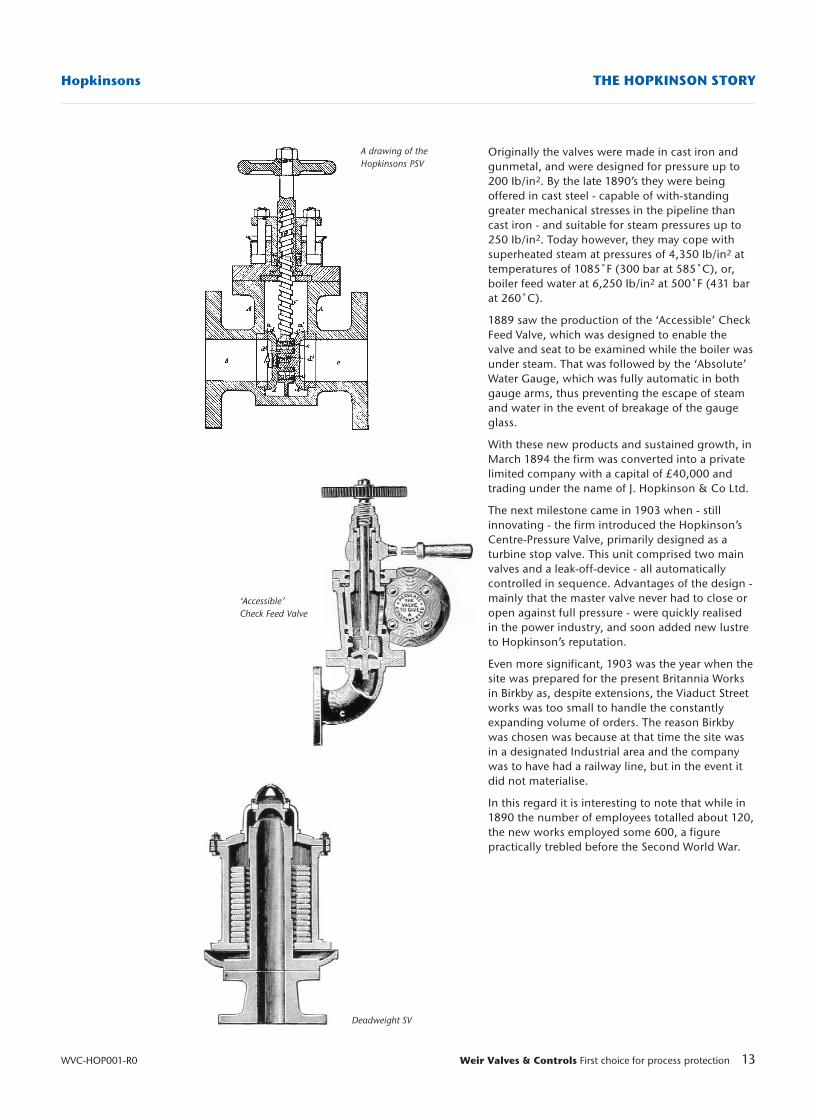
A drawing of theHopkinsons PSV
Deadweight SV
‘Accessible’ Check Feed Valve
Originally the valves were made in cast iron andgunmetal, and were designed for pressure up to200 Ib/in2. By the late 1890’s they were beingoffered in cast steel - capable of with-standinggreater mechanical stresses in the pipeline thancast iron - and suitable for steam pressures up to250 Ib/in2. Today however, they may cope withsuperheated steam at pressures of 4,350 Ib/in2 attemperatures of 1085˚F (300 bar at 585˚C), or,boiler feed water at 6,250 Ib/in2 at 500˚F (431 barat 260˚C).
1889 saw the production of the ‘Accessible’ CheckFeed Valve, which was designed to enable thevalve and seat to be examined while the boiler wasunder steam. That was followed by the ‘Absolute’Water Gauge, which was fully automatic in bothgauge arms, thus preventing the escape of steamand water in the event of breakage of the gaugeglass.
With these new products and sustained growth, inMarch 1894 the firm was converted into a privatelimited company with a capital of £40,000 andtrading under the name of J. Hopkinson & Co Ltd.
The next milestone came in 1903 when - stillinnovating - the firm introduced the Hopkinson’sCentre-Pressure Valve, primarily designed as aturbine stop valve. This unit comprised two mainvalves and a leak-off-device - all automaticallycontrolled in sequence. Advantages of the design -mainly that the master valve never had to close oropen against full pressure - were quickly realisedin the power industry, and soon added new lustreto Hopkinson’s reputation.
Even more significant, 1903 was the year when thesite was prepared for the present Britannia Worksin Birkby as, despite extensions, the Viaduct Streetworks was too small to handle the constantlyexpanding volume of orders. The reason Birkbywas chosen was because at that time the site wasin a designated Industrial area and the companywas to have had a railway line, but in the event itdid not materialise.
In this regard it is interesting to note that while in1890 the number of employees totalled about 120,the new works employed some 600, a figurepractically trebled before the Second World War.
14 Weir Valves & Controls First choice for process protection WVC-HOP001-R0
HopkinsonsTHE HOPKINSON STORY
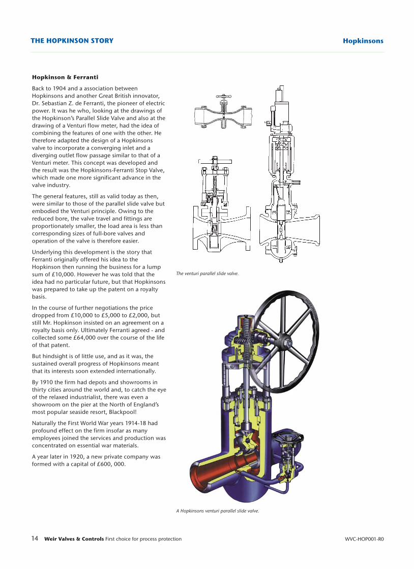
A Hopkinsons venturi parallel slide valve.
The venturi parallel slide valve.
Hopkinson & Ferranti
Back to 1904 and a association betweenHopkinsons and another Great British innovator,Dr. Sebastian Z. de Ferranti, the pioneer of electricpower. It was he who, looking at the drawings ofthe Hopkinson’s Parallel Slide Valve and also at thedrawing of a Venturi flow meter, had the idea ofcombining the features of one with the other. Hetherefore adapted the design of a Hopkinsonsvalve to incorporate a converging inlet and adiverging outlet flow passage similar to that of aVenturi meter. This concept was developed andthe result was the Hopkinsons-Ferranti Stop Valve,which made one more significant advance in thevalve industry.
The general features, still as valid today as then,were similar to those of the parallel slide valve butembodied the Venturi principle. Owing to thereduced bore, the valve travel and fittings areproportionately smaller, the load area is less thancorresponding sizes of full-bore valves andoperation of the valve is therefore easier.
Underlying this development is the story thatFerranti originally offered his idea to theHopkinson then running the business for a lumpsum of £10,000. However he was told that theidea had no particular future, but that Hopkinsonswas prepared to take up the patent on a royaltybasis.
In the course of further negotiations the pricedropped from £10,000 to £5,000 to £2,000, butstill Mr. Hopkinson insisted on an agreement on aroyalty basis only. Ultimately Ferranti agreed - andcollected some £64,000 over the course of the lifeof that patent.
But hindsight is of little use, and as it was, thesustained overall progress of Hopkinsons meantthat its interests soon extended internationally.
By 1910 the firm had depots and showrooms inthirty cities around the world and, to catch the eyeof the relaxed industrialist, there was even ashowroom on the pier at the North of England’smost popular seaside resort, Blackpool!
Naturally the First World War years 1914-18 hadprofound effect on the firm insofar as manyemployees joined the services and production wasconcentrated on essential war materials.
A year later in 1920, a new private company wasformed with a capital of £600, 000.
15Weir Valves & Controls First choice for process protection
Hopkinsons THE HOPKINSON STORY
WVC-HOP001-R0
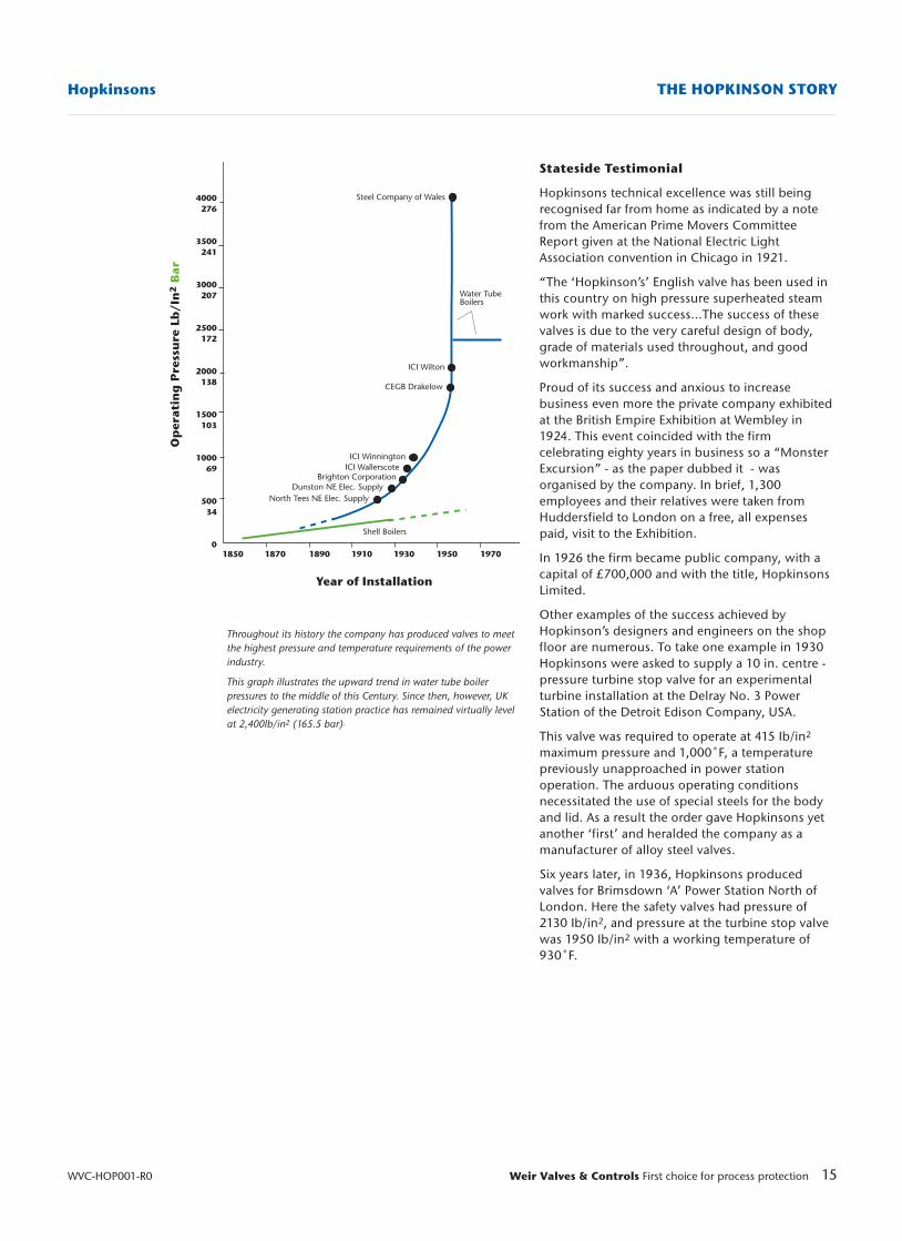
Throughout its history the company has produced valves to meetthe highest pressure and temperature requirements of the powerindustry.
This graph illustrates the upward trend in water tube boilerpressures to the middle of this Century. Since then, however, UKelectricity generating station practice has remained virtually levelat 2,400lb/in2 (165.5 bar).
Stateside Testimonial
Hopkinsons technical excellence was still beingrecognised far from home as indicated by a notefrom the American Prime Movers CommitteeReport given at the National Electric LightAssociation convention in Chicago in 1921.
“The ‘Hopkinson’s’ English valve has been used inthis country on high pressure superheated steamwork with marked success...The success of thesevalves is due to the very careful design of body,grade of materials used throughout, and goodworkmanship”.
Proud of its success and anxious to increasebusiness even more the private company exhibitedat the British Empire Exhibition at Wembley in1924. This event coincided with the firmcelebrating eighty years in business so a “MonsterExcursion” - as the paper dubbed it - wasorganised by the company. In brief, 1,300employees and their relatives were taken fromHuddersfield to London on a free, all expensespaid, visit to the Exhibition.
In 1926 the firm became public company, with acapital of £700,000 and with the title, HopkinsonsLimited.
Other examples of the success achieved byHopkinson’s designers and engineers on the shopfloor are numerous. To take one example in 1930Hopkinsons were asked to supply a 10 in. centre -pressure turbine stop valve for an experimentalturbine installation at the Delray No. 3 PowerStation of the Detroit Edison Company, USA.
This valve was required to operate at 415 Ib/in2
maximum pressure and 1,000˚F, a temperaturepreviously unapproached in power stationoperation. The arduous operating conditionsnecessitated the use of special steels for the bodyand lid. As a result the order gave Hopkinsons yetanother ‘first’ and heralded the company as amanufacturer of alloy steel valves.
Six years later, in 1936, Hopkinsons producedvalves for Brimsdown ‘A’ Power Station North ofLondon. Here the safety valves had pressure of2130 Ib/in2, and pressure at the turbine stop valvewas 1950 Ib/in2 with a working temperature of930˚F.
Year of Installation
Op
erat
ing
Pre
ssu
re L
b/I
n2
Bar
War Work
A few years later Britain was involved in theSecond World War when the efficiency andcontinuous operation of the power stations andvital industrial plants were essential. Since these inturn depended on the reliability of boilermountings and valves, Hopkinson’s products weregiven the highest priority. Actually for some timeprior to September 1939 the firm had substantialorders for equipment for the new power andprocess installations in Government factoriesthroughout the country, in addition to extensionsto electricity generating stations which thenacquired a new urgency.
Furthermore there was the extra production forthe war effort in the form of components forarmaments, aircraft, tanks and even assemblies for‘Asdic’ submarine detection instruments.
Britain Rebuilds
Post war nationalisation of Britain’s electricityindustry brought in considerable orders forHopkinsons when the new authority commenceda national plan for the modernisation of existingplant and the construction of additional powerstations. Once more, the company’s expertise wascalled upon to provide the best in the design andmanufacture of valves and associated products tomeet this challenge.
In fact, as the industry’s expansion programcontinued, Hopkinsons supplied practically two-thirds of the valve requirements and over a third ofthe sootblower systems for the fifty 500 MWelectricity generating units built in the 1960’s.
16 Weir Valves & Controls First choice for process protection WVC-HOP001-R0
HopkinsonsTHE HOPKINSON STORY
High investment in the machine shop.
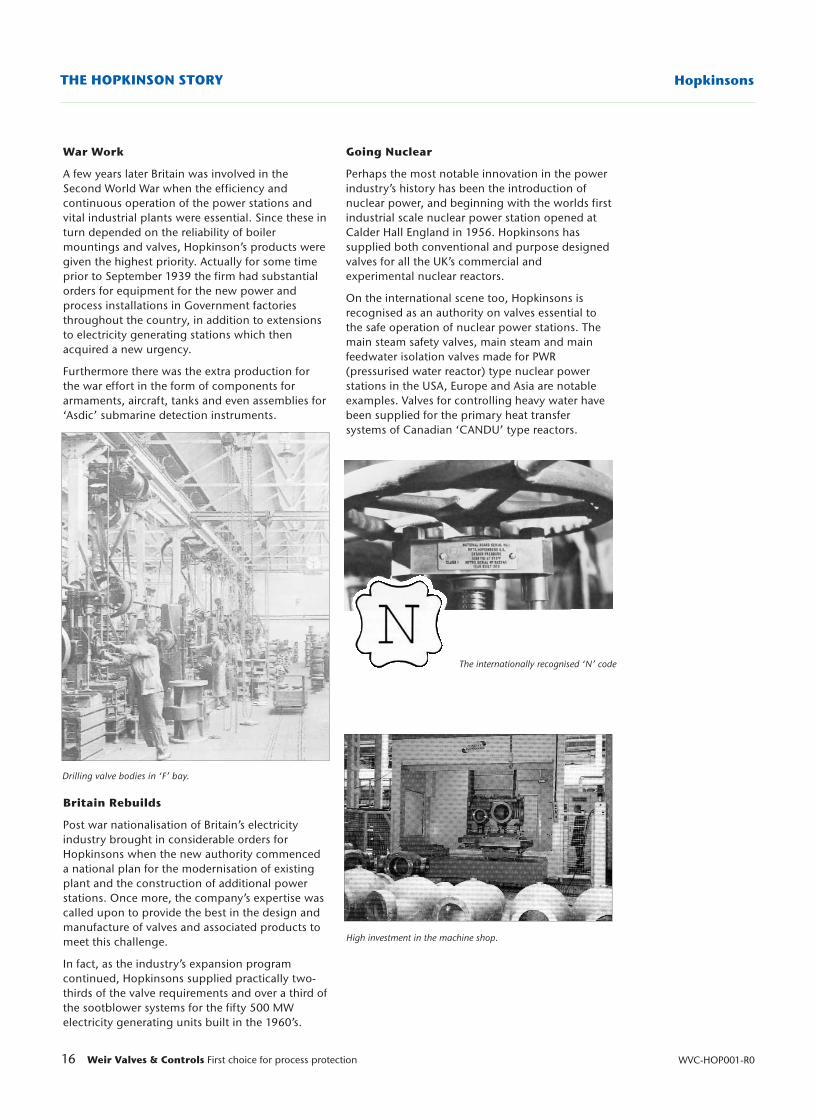
The internationally recognised ‘N’ code
Going Nuclear
Perhaps the most notable innovation in the powerindustry’s history has been the introduction ofnuclear power, and beginning with the worlds firstindustrial scale nuclear power station opened atCalder Hall England in 1956. Hopkinsons hassupplied both conventional and purpose designedvalves for all the UK’s commercial andexperimental nuclear reactors.
On the international scene too, Hopkinsons isrecognised as an authority on valves essential tothe safe operation of nuclear power stations. Themain steam safety valves, main steam and mainfeedwater isolation valves made for PWR(pressurised water reactor) type nuclear powerstations in the USA, Europe and Asia are notableexamples. Valves for controlling heavy water havebeen supplied for the primary heat transfersystems of Canadian ‘CANDU’ type reactors.
Drilling valve bodies in ‘F’ bay.
17Weir Valves & Controls First choice for process protection
Hopkinsons THE HOPKINSON STORY
WVC-HOP001-R0
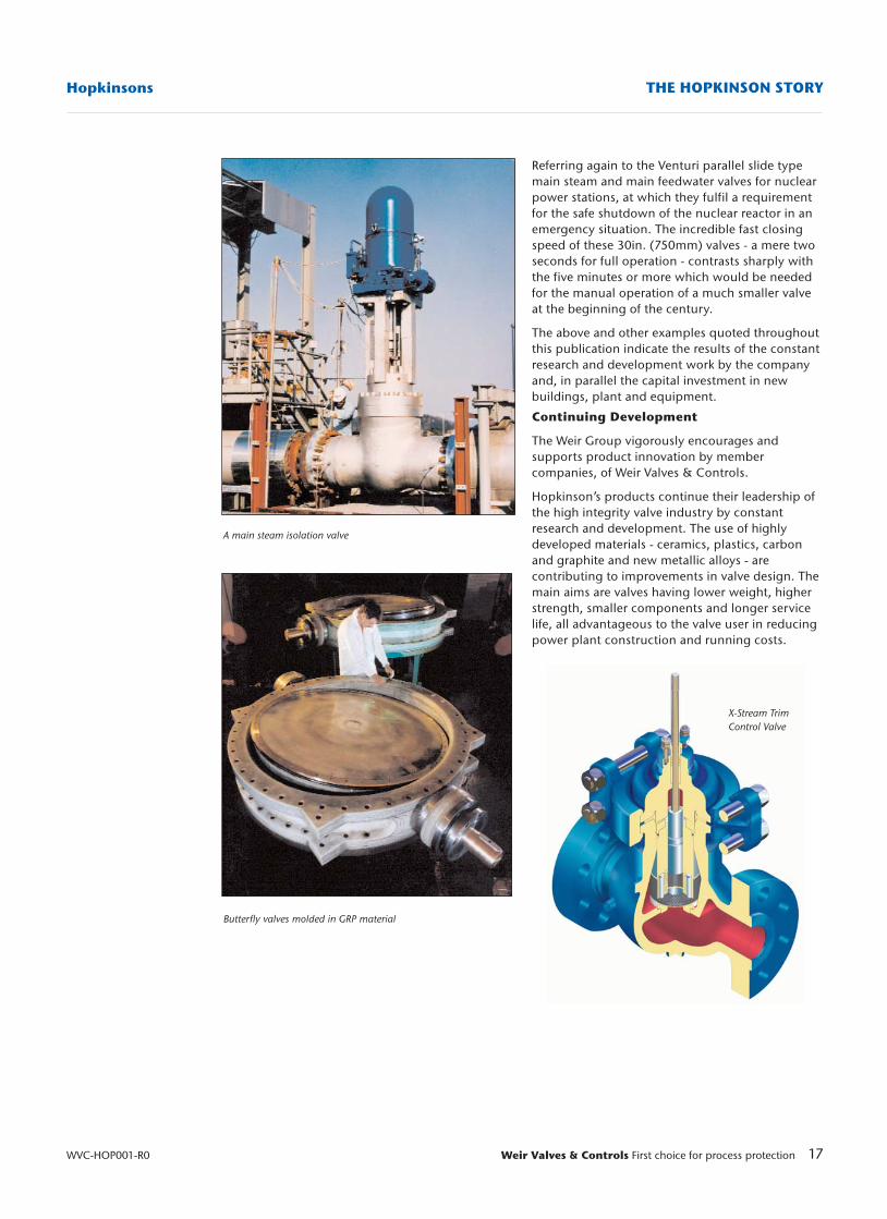
A main steam isolation valve
Butterfly valves molded in GRP material
X-Stream TrimControl Valve
Referring again to the Venturi parallel slide typemain steam and main feedwater valves for nuclearpower stations, at which they fulfil a requirementfor the safe shutdown of the nuclear reactor in anemergency situation. The incredible fast closingspeed of these 30in. (750mm) valves - a mere twoseconds for full operation - contrasts sharply withthe five minutes or more which would be neededfor the manual operation of a much smaller valveat the beginning of the century.
The above and other examples quoted throughoutthis publication indicate the results of the constantresearch and development work by the companyand, in parallel the capital investment in newbuildings, plant and equipment.
Continuing Development
The Weir Group vigorously encourages andsupports product innovation by membercompanies, of Weir Valves & Controls.
Hopkinson’s products continue their leadership ofthe high integrity valve industry by constantresearch and development. The use of highlydeveloped materials - ceramics, plastics, carbonand graphite and new metallic alloys - arecontributing to improvements in valve design. Themain aims are valves having lower weight, higherstrength, smaller components and longer servicelife, all advantageous to the valve user in reducingpower plant construction and running costs.
18 Weir Valves & Controls First choice for process protection WVC-HOP001-R0
HopkinsonsTHE HOPKINSON STORY
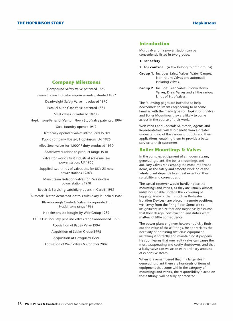
Company MilestonesCompound Safety Valve patented 1852
Steam Engine Indicator improvements patented 1857
Deadweight Safety Valve introduced 1870
Parallel Slide Gate Valve patented 1881
Steel valves introduced 1890’s
Hopkinsons-Ferranti (Venturi Flow) Stop Valve patented 1904
Steel foundry opened 1912
Electrically operated valves introduced 1920’s
Public company floated, Hopkinsons Ltd 1926
Alloy Steel valves for 1,000˚F duty produced 1930
Sootblowers added to product range 1938
Valves for world’s first industrial scale nuclearpower station, UK 1956
Supplied two-thirds of valves etc. for UK’s 25 newpower stations 1960’s
Main Steam Isolation Valves for PWR nuclearpower stations 1970
Repair & Servicing subsidiary opens in Cardiff 1981
Autotork Electric Actuator/Controls subsidiary launched 1987
Blakeborough Controls Valves incorporated inHopkinsons range 1988
Hopkinsons Ltd bought by Weir Group 1989
Oil & Gas Industry pipeline valves range announced 1993
Acquisition of Batley Valve 1996
Acquisition of Sebim Group 1998
Acquisition of Flowguard 1999
Formation of Weir Valves & Controls 2002
IntroductionMost valves on a power station can beconveniently listed in two groups,
1. For safety
2. For control (A few belong to both groups)
Group 1. Includes Safety Valves, Water Gauges, Non-return Valves and automatic Isolating Valves.
Group 2. Includes Feed Valves, Blown Down Valves, Drain Valves and all the various kinds of Stop Valves.
The following pages are intended to helpnewcomers to steam engineering to becomefamiliar with the many types of Hopkinson’s Valvesand Boiler Mountings they are likely to comeacross in the course of their work.
Weir Valves and Controls Salesmen, Agents andRepresentatives will also benefit from a greaterunderstanding of the various products and theirapplications, enabling them to provide a betterservice to their customers.
Boiler Mountings & ValvesIn the complex equipment of a modern steam,generating plant, the boiler mountings andauxiliary valves rank among the most importantitems, as the safety and smooth working of thewhole plant depends to a great extent on theirsuitability and correct design.
The casual observer would hardly notice themountings and valves, as they are usually almostindistinguishable under a thick covering oflagging. Many of them - such as Re-heaterIsolation Devices - are placed in remote positions,well away from the firing floor. Some are soinsignificant in size that one might easily assumethat their design, construction and duties werematters of little consequence.
The power plant engineer however quickly findsout the value of these fittings. He appreciates thenecessity of obtaining first class equipment,installing it correctly and maintaining it properly.He soon learns that one faulty valve can cause themost exasperating and costly shutdowns, and thata leaky valve can waste an extraordinary amountof expensive steam.
When it is remembered that in a large steamgenerating plant there are hundreds of items ofequipment that come within the category ofmountings and valves, the responsibility placed onthese fittings will be fully appreciated.
19Weir Valves & Controls First choice for process protection
Hopkinsons PARALLEL SLIDE GATE VALVES
WVC-HOP001-R0
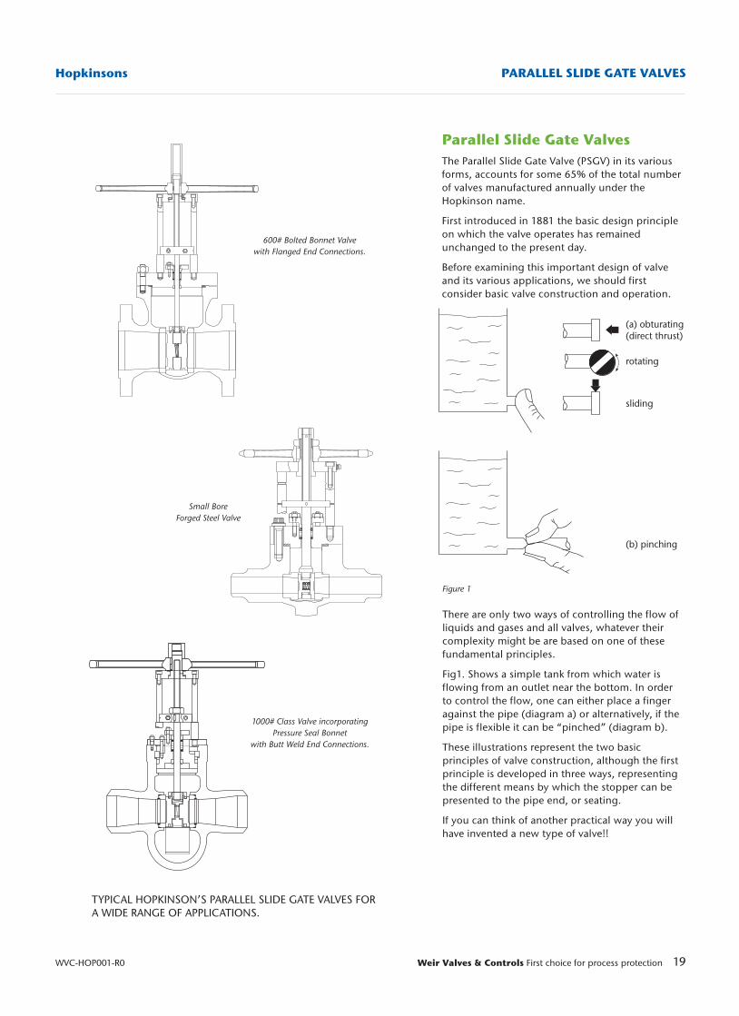
Parallel Slide Gate ValvesThe Parallel Slide Gate Valve (PSGV) in its variousforms, accounts for some 65% of the total numberof valves manufactured annually under theHopkinson name.
First introduced in 1881 the basic design principleon which the valve operates has remainedunchanged to the present day.
Before examining this important design of valveand its various applications, we should firstconsider basic valve construction and operation.
TYPICAL HOPKINSON’S PARALLEL SLIDE GATE VALVES FORA WIDE RANGE OF APPLICATIONS.
Figure 1
600# Bolted Bonnet Valvewith Flanged End Connections.
Small BoreForged Steel Valve
1000# Class Valve incorporatingPressure Seal Bonnet
with Butt Weld End Connections.
(a) obturating(direct thrust)
rotating
sliding
(b) pinching
There are only two ways of controlling the flow ofliquids and gases and all valves, whatever theircomplexity might be are based on one of thesefundamental principles.
Fig1. Shows a simple tank from which water isflowing from an outlet near the bottom. In orderto control the flow, one can either place a fingeragainst the pipe (diagram a) or alternatively, if thepipe is flexible it can be “pinched” (diagram b).
These illustrations represent the two basicprinciples of valve construction, although the firstprinciple is developed in three ways, representingthe different means by which the stopper can bepresented to the pipe end, or seating.
If you can think of another practical way you willhave invented a new type of valve!!
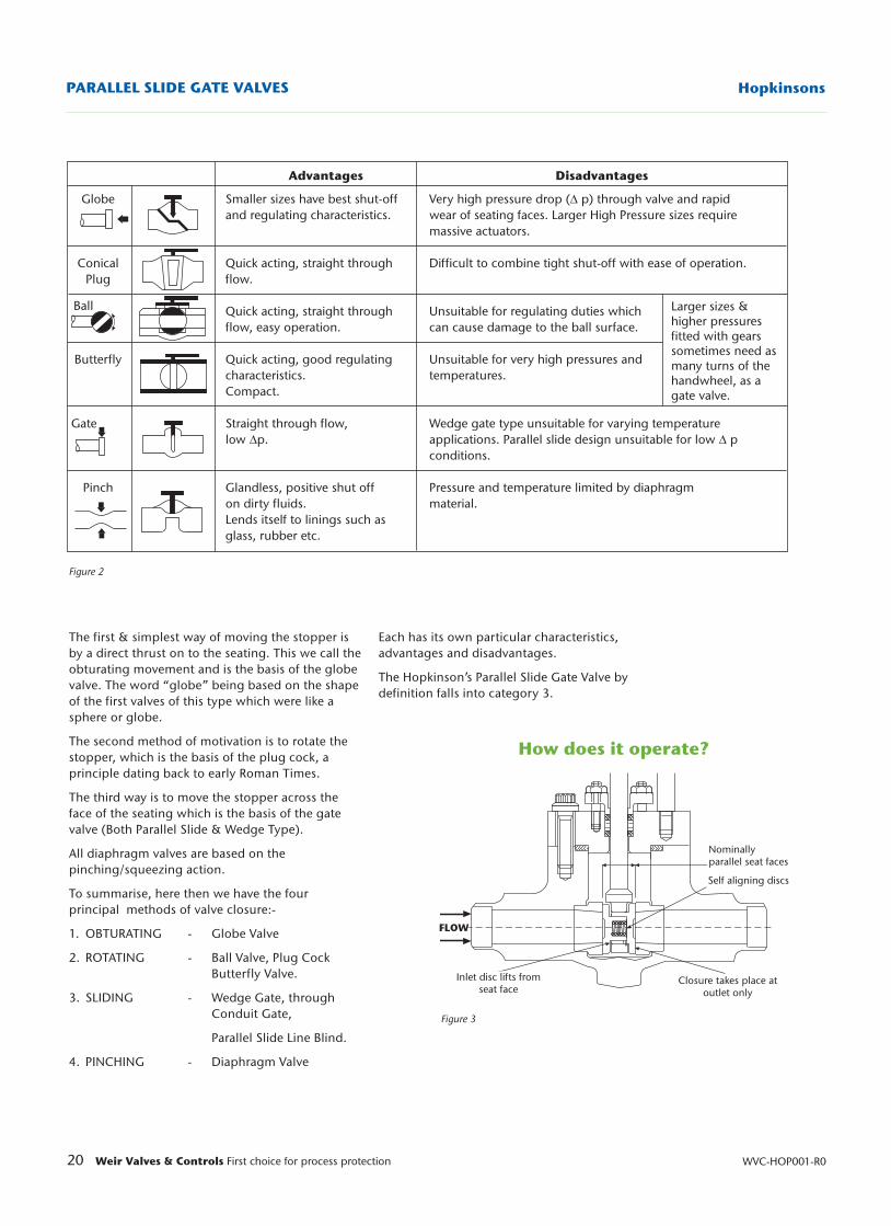
Advantages Disadvantages
Globe Smaller sizes have best shut-off Very high pressure drop (∆ p) through valve and rapidand regulating characteristics. wear of seating faces. Larger High Pressure sizes require
massive actuators.
Conical Quick acting, straight through Difficult to combine tight shut-off with ease of operation.Plug flow.
Ball Quick acting, straight through Unsuitable for regulating duties whichflow, easy operation. can cause damage to the ball surface.
Butterfly Quick acting, good regulating Unsuitable for very high pressures andcharacteristics. temperatures.Compact.
Gate Straight through flow, Wedge gate type unsuitable for varying temperature low ∆p. applications. Parallel slide design unsuitable for low ∆ p
conditions.
Pinch Glandless, positive shut off Pressure and temperature limited by diaphragmon dirty fluids. material.Lends itself to linings such asglass, rubber etc.
20 Weir Valves & Controls First choice for process protection WVC-HOP001-R0
HopkinsonsPARALLEL SLIDE GATE VALVES
Figure 2
How does it operate?
Nominally parallel seat faces
Self aligning discs
Closure takes place atoutlet only
Inlet disc lifts fromseat face
FLOW
Figure 3
Larger sizes &higher pressuresfitted with gearssometimes need asmany turns of thehandwheel, as agate valve.
The first & simplest way of moving the stopper isby a direct thrust on to the seating. This we call theobturating movement and is the basis of the globevalve. The word “globe” being based on the shapeof the first valves of this type which were like asphere or globe.
The second method of motivation is to rotate thestopper, which is the basis of the plug cock, aprinciple dating back to early Roman Times.
The third way is to move the stopper across theface of the seating which is the basis of the gatevalve (Both Parallel Slide & Wedge Type).
All diaphragm valves are based on thepinching/squeezing action.
To summarise, here then we have the fourprincipal methods of valve closure:-
1. OBTURATING - Globe Valve
2. ROTATING - Ball Valve, Plug Cock Butterfly Valve.
3. SLIDING - Wedge Gate, through Conduit Gate,
Parallel Slide Line Blind.
4. PINCHING - Diaphragm Valve
Each has its own particular characteristics,advantages and disadvantages.
The Hopkinson’s Parallel Slide Gate Valve bydefinition falls into category 3.
21Weir Valves & Controls First choice for process protection
Hopkinsons PARALLEL SLIDE GATE VALVES
WVC-HOP001-R0
1. Low Pressure Valves i.e. 150 & 300 Class Ratings having a Full Bore and incorporating a Bolted Bonnet.
2. High Pressure valves i.e. 600 - 3100 Class Ratings having a Full Bore and incorporating a Pressure Seal Bonnet. [NB Exception is the 600 Class Valve in WCB, WC6 & WC9, which has a Bolted Bonnet].
3. High Pressure valves i.e. 600 - 3100 Class Ratings having a Venturi Bore and incorporating a Pressure Seal Bonnet. [NB Exception is the 600 Class valve in WCB, WC6 &WC9, which has a bolted Bonnet].
The range of valves listed above are essentially insizes 5” - 30” but there is also a complementaryrange of smaller sizes of valves manufactured byHopkinsons in ASTM A105 Forged Carbon Steeland ASTM A182-F22 Forged Alloy Steel.
This range of Parallel Slide Valves is utilised onPipeline Isolation duties and in a modified form, asa Bypass or Equalising Bypass for the larger sizeHopkinson’s Parallel Slide Valves.
Let us first consider the design features of the LowPressure Full Bore Valve; -
1. Complies with the design requirement of ASME B16.34 1998 In 150 & 300 Class Ratings.
2. Overall length in accordance with ASME B16.10
3. Flanges in accordance with ASME B16.5 with alternatives available if required.
4. Butt weld ends to ASME B16.25 with provision for alternative profiles should they be required.
5. Available in Nominal Bore sizes 21⁄2" to 30".
Valve Construction The valve has been designed with a boltedrectangular Body/Cover assembly incorporatingan exfoliated graphite gasket.
All valves operated with a direct mountedhandwheel are of the two pillar design with rollerthrust bearings fitted in the bridge to provide lowfriction operation.
When electric, pneumatic or hydraulic actuation isrequired, there is provision on the standard valvecover to fit a four-pillar arrangement to providethe necessary additional support.
In considering the operation of a Parallel SlideValve, an important fact to remember is that in itsbasic form i.e. without special seats or bypassarrangements, the valve is bi-directional.
Fig 3. Shows a typical Parallel Slide Valve sealingarrangement, incorporating a male and femaledisc held against their respective seat faces bymeans of an internal spring.
The purpose of the specially designed spring is toprovide initial sealing of the valve under no loadconditions.
When the valve is under pressure, the force of themedium (steam or water) on the inlet disks movesit away from its seat face and compresses thespring.
This action allows the medium to enter andpressurize the intergate space (i.e. that part of thevalve between the seat faces) and force the outletdisk against its seat face.
Once the pressure in the intergate space is equalto the inlet pressure, the inlet disk is returned to itsseat face by the action of the spring.
The intergate pressure continues to act against theback face of the outlet disk, maintaining isolationof the valve/pipeline.
THE GREATER THE LINE PRESSURE, THE TIGHTERTHE SEAL.
What is a Parallel Slide GateValve Used For?The application of a Parallel Slide Gate Valve isessentially that of providing positive isolation onthe following duties:-
1. Steam & Water services in the Power Generation Industry.
2. Process Steam & Water applications in the Petro-Chemical and PaperMaking Industries.
3. Fuel or Lubricating Oil distribution.
In certain circumstances, a parallel slide valve maybe used on regulating duties - such as Boiler FeedPump Start up - by the fitting of a “Vee Port”outlet seat. This feature will be explained in detaillater on in the text.
Product FeaturesSo far, we have considered Parallel Slide GateValves only in the most general terms. However, itshould be appreciated that there are in fact, THREEspecific Hopkinson designs manufactured in Castand Forged Carbon and Alloy Steels i.e. ASTMA216-WCB, ASTM A217-WC6, ASTM A217-WC9,ASTM A105 & ASTM 182 Gr. F22. For special hightemperature applications, a select range of valvesis available in C-12A Modified 9% Cr.
22 Weir Valves & Controls First choice for process protection WVC-HOP001-R0
HopkinsonsPARALLEL SLIDE GATE VALVES
A substantial stem stop (together with an indicatorplate on the valve pillars) provides positiveindication of the degree of opening/closure of thevalve and prevents rotation of the stem.
The valve is closed when the stem stop reachesthe lower shoulder of the pillars and open whenopposite the open mark at the opposite end of thepillars.
A Backseating facility is incorporated in the coverand is brought into effect by opening the valvebeyond the ‘Open’ mark on the indicator plateuntil resistance is felt.
The sealing action is achieved through a seatingface on the end of the disc holder contacting aBackseat bush fitted into the cover below the baseof the stuffing box.
It is important to remember that irrespective ofwhat may be written in Contract/Tenderingspecifications, the purpose of backseating is NOTto allow repacking of the stuffing box when thevalve is under pressure.
The function of a backseating facility is to isolate aleaking stuffing box, thus preventing stemdamage, until the problem can be attended towhen the system is shut down and no longer live.
Failure to follow this ruling can result in seriousinjury to anyone attempting to re-pack a glandwhile the valve is under pressure.
As with all other Hopkinsons products, thestuffing box packing material in the Low PressureFull Bore Parallel Slide Valve is Exfoliated Graphite.
The seats and discs are the very heart of a ParallelSlide Valve. Sound design and selection of thecorrect materials are essential to its properfunctioning.
Over many years experience, Hopkinsons havedeveloped their own proprietary material‘PLATNAM’ for use on the wide variety of seatingapplications across their extensive product range.
On the Low Pressure Parallel Slide Valves, the seatsare manufactured from No.12 Platinum (which is ahigh nickel content steel) and are a press fit intothe valve body.
Discs on the smaller sizes of valve are producedfrom solid No.12 Platinum castings while thelarger sizes (above size 4”) are manufactured fromsteel with a No.6 Stellite facing.
Comparison of the ParallelSlide Gate Valve with theWedge Gate ValveWe learned earlier that a Parallel Slide Valve is a“position seating” valve, utilising line pressure inorder to effect closure. Originally invented byHopkinsons, it is also manufactured by a numberof other Companies around the world i.e.
MANUFACTURER LOCATIONBailey - Birkett UKShaw Valves UKTaylor Valves Ltd UKPeter Smith UKDewrance - Tyco Germany & ItalySapag - Tyco FranceTOA JapanUTSUE JapanMalbranque FranceVelan CanadaAudco IndiaBabcock Borsig SpainCrane Pacific USA
There are also a number of other companiesworldwide who manufacture a Parallel seatingvalve but this design utilises a mechanical“spreading” disc feature and cannot beconsidered a true parallel slide valve. In theintroduction to this manual, we examined thevarious types of valves and their applications. Eachtype has its own special capability but no oneparticular valve can satisfy a number of functionsadequately.
Such an example is a Globe Valve which hasexcellent regulating characteristics but at theexpense of the seating surfaces. These can quicklybecome eroded to the point that completeisolation of the valve is impossible.
Essentially a Parallel Slide Valve is an isolationvalve and performs best on systems with a highpressure differential across the seating surfaces.Where no such pressure differential exists, analternative solution is required. A Wedge GateValve, which mechanically seals on both inlet andoutlet seat faces without the assistance of linepressure is a suitable option.
Unfortunately Wedge Gate valves which are usedextensively in the Oil, Petro-Chemical and Refineryprocesses are also utilised in Power GenerationIndustry with less than satisfactory results.
To understand the reasons for this, we mustcompare the relative design features of both theParallel Slide and Wedge Gate Valve.
23Weir Valves & Controls First choice for process protection
Hopkinsons PARALLEL SIDE GATE VALVES
WVC-HOP001-R0
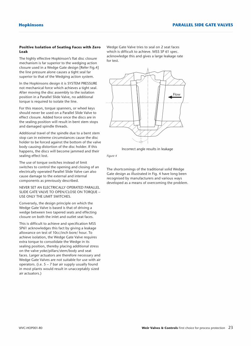
Wedge Gate Valve tries to seal on 2 seat faceswhich is difficult to achieve. MSS SP 61 spec.acknowledge this and gives a large leakage ratefor test.
Figure 4
The shortcomings of the traditional solid WedgeGate design as illustrated in Fig. 4 have long beenrecognised by manufacturers and various waysdeveloped as a means of overcoming the problem.
Positive Isolation of Seating Faces with ZeroLeak
The highly effective Hopkinson’s flat disc closuremechanism is far superior to the wedging actionclosure used in a Wedge Gate design [Refer Fig.4]the line pressure alone causes a tight seal farsuperior to that of the Wedging action system.
In the Hopkinsons design it is SYSTEM PRESSUREnot mechanical force which achieves a tight seal.After moving the disc assembly to the isolationposition in a Parallel Slide Valve, no additionaltorque is required to isolate the line.
For this reason, torque spanners, or wheel keysshould never be used on a Parallel Slide Valve toeffect closure. Added force once the discs are inthe sealing position will result in bent stem stopsand damaged spindle threads.
Additional travel of the spindle due to a bent stemstop can in extreme circumstances cause the discholder to be forced against the bottom of the valvebody causing distortion of the disc holder. If thishappens, the discs will become jammed and theirsealing effect lost.
The use of torque switches instead of limitswitches to control the opening and closing of anelectrically operated Parallel Slide Valve can alsocause damage to the external and internalcomponents as previously described.
NEVER SET AN ELECTRICALLY OPERATED PARALLELSLIDE GATE VALVE TO OPEN/CLOSE ON TORQUE –USE ONLY THE LIMIT SWITCHES.
Conversely, the design principle on which theWedge Gate Valve is based is that of driving awedge between two tapered seats and effectingclosure on both the inlet and outlet seat faces.
This is difficult to achieve and specification MSSSP61 acknowledges this fact by giving a leakageallowance on test of 10cc/inch bore/ hour. Toachieve isolation, the Wedge Gate Valve requiresextra torque to consolidate the Wedge in itssealing position, thereby placing additional stresson the valve yoke/pillars/stem/body and seatfaces. Larger actuators are therefore necessary andWedge Gate Valves are not suitable for use with airoperators. (i.e. 5 – 7 bar air supply usually foundin most plants would result in unacceptably sizedair actuators.)
Flow
Incorrect angle results in leakage
24 Weir Valves & Controls First choice for process protection WVC-HOP001-R0
HopkinsonsPARALLEL SLIDE GATE VALVES
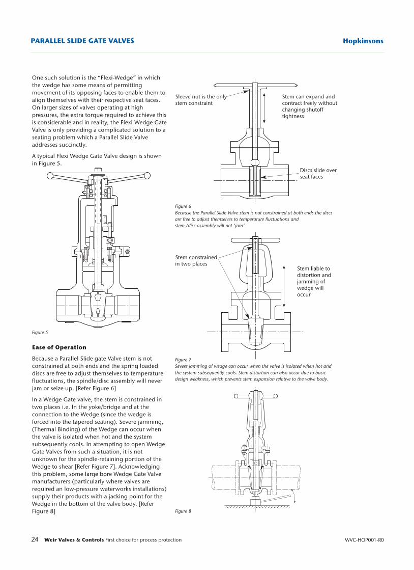
One such solution is the “Flexi-Wedge” in whichthe wedge has some means of permittingmovement of its opposing faces to enable them toalign themselves with their respective seat faces.On larger sizes of valves operating at highpressures, the extra torque required to achieve thisis considerable and in reality, the Flexi-Wedge GateValve is only providing a complicated solution to aseating problem which a Parallel Slide Valveaddresses succinctly.
A typical Flexi Wedge Gate Valve design is shownin Figure 5.
Ease of Operation
Because a Parallel Slide gate Valve stem is notconstrained at both ends and the spring loadeddiscs are free to adjust themselves to temperaturefluctuations, the spindle/disc assembly will neverjam or seize up. [Refer Figure 6]
In a Wedge Gate valve, the stem is constrained intwo places i.e. In the yoke/bridge and at theconnection to the Wedge (since the wedge isforced into the tapered seating). Severe jamming,(Thermal Binding) of the Wedge can occur whenthe valve is isolated when hot and the systemsubsequently cools. In attempting to open WedgeGate Valves from such a situation, it is notunknown for the spindle-retaining portion of theWedge to shear [Refer Figure 7]. Acknowledgingthis problem, some large bore Wedge Gate Valvemanufacturers (particularly where valves arerequired an low-pressure waterworks installations)supply their products with a jacking point for theWedge in the bottom of the valve body. [ReferFigure 8]
Figure 6Because the Parallel Slide Valve stem is not constrained at both ends the discsare free to adjust themselves to temperature fluctuations andstem /disc assembly will not ‘jam’
Figure 7Severe jamming of wedge can occur when the valve is isolated when hot andthe system subsequently cools. Stem distortion can also occur due to basicdesign weakness, which prevents stem expansion relative to the valve body.
Figure 8
Figure 5
Sleeve nut is the onlystem constraint
Stem can expand andcontract freely withoutchanging shutoff tightness
Discs slide over seat faces
Stem constrainedin two places
Stem liable todistortion andjamming ofwedge will occur
25Weir Valves & Controls First choice for process protection
Hopkinsons PARALLEL SLIDE GATE VALVES
WVC-HOP001-R0
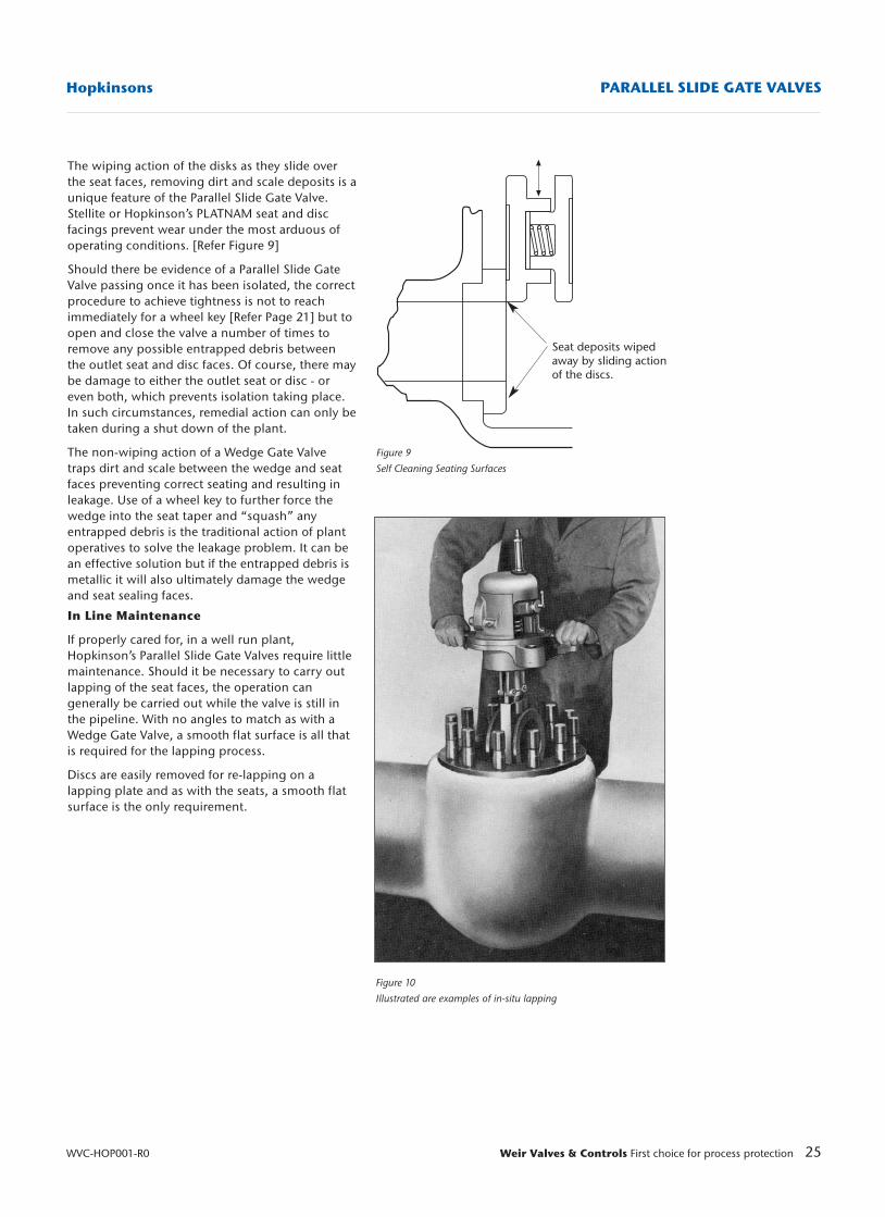
Figure 10
Illustrated are examples of in-situ lapping
Figure 9
Self Cleaning Seating Surfaces
Seat deposits wipedaway by sliding actionof the discs.
The wiping action of the disks as they slide overthe seat faces, removing dirt and scale deposits is aunique feature of the Parallel Slide Gate Valve.Stellite or Hopkinson’s PLATNAM seat and discfacings prevent wear under the most arduous ofoperating conditions. [Refer Figure 9]
Should there be evidence of a Parallel Slide GateValve passing once it has been isolated, the correctprocedure to achieve tightness is not to reachimmediately for a wheel key [Refer Page 21] but toopen and close the valve a number of times toremove any possible entrapped debris betweenthe outlet seat and disc faces. Of course, there maybe damage to either the outlet seat or disc - oreven both, which prevents isolation taking place.In such circumstances, remedial action can only betaken during a shut down of the plant.
The non-wiping action of a Wedge Gate Valvetraps dirt and scale between the wedge and seatfaces preventing correct seating and resulting inleakage. Use of a wheel key to further force thewedge into the seat taper and “squash” anyentrapped debris is the traditional action of plantoperatives to solve the leakage problem. It can bean effective solution but if the entrapped debris ismetallic it will also ultimately damage the wedgeand seat sealing faces.
In Line Maintenance
If properly cared for, in a well run plant,Hopkinson’s Parallel Slide Gate Valves require littlemaintenance. Should it be necessary to carry outlapping of the seat faces, the operation cangenerally be carried out while the valve is still inthe pipeline. With no angles to match as with aWedge Gate Valve, a smooth flat surface is all thatis required for the lapping process.
Discs are easily removed for re-lapping on alapping plate and as with the seats, a smooth flatsurface is the only requirement.
26 Weir Valves & Controls First choice for process protection WVC-HOP001-R0
HopkinsonsPARALLEL SLIDE GATE VALVES
Gland Stud
Disk springs& retaining cup
Gland flange
Gland packing
Carbon sleeve
Figure 13
Stem
Gland nut
Gland Follower
Bonnet
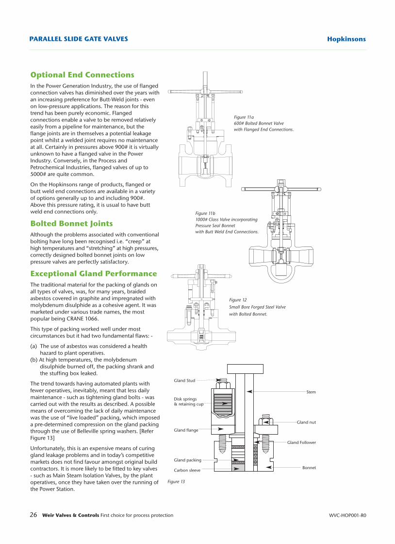
Optional End ConnectionsIn the Power Generation Industry, the use of flangedconnection valves has diminished over the years withan increasing preference for Butt-Weld joints - evenon low-pressure applications. The reason for thistrend has been purely economic. Flangedconnections enable a valve to be removed relativelyeasily from a pipeline for maintenance, but theflange joints are in themselves a potential leakagepoint whilst a welded joint requires no maintenanceat all. Certainly in pressures above 900# it is virtuallyunknown to have a flanged valve in the PowerIndustry. Conversely, in the Process andPetrochemical Industries, flanged valves of up to5000# are quite common.
On the Hopkinsons range of products, flanged orbutt weld end connections are available in a varietyof options generally up to and including 900#.Above this pressure rating, it is usual to have buttweld end connections only.
Bolted Bonnet JointsAlthough the problems associated with conventionalbolting have long been recognised i.e. “creep” athigh temperatures and “stretching” at high pressures,correctly designed bolted bonnet joints on lowpressure valves are perfectly satisfactory.
Exceptional Gland PerformanceThe traditional material for the packing of glands onall types of valves, was, for many years, braidedasbestos covered in graphite and impregnated withmolybdenum disulphide as a cohesive agent. It wasmarketed under various trade names, the mostpopular being CRANE 1066.
This type of packing worked well under mostcircumstances but it had two fundamental flaws: -
(a) The use of asbestos was considered a health hazard to plant operatives.
(b) At high temperatures, the molybdenum disulphide burned off, the packing shrank and the stuffing box leaked.
The trend towards having automated plants withfewer operatives, inevitably, meant that less dailymaintenance - such as tightening gland bolts - wascarried out with the results as described. A possiblemeans of overcoming the lack of daily maintenancewas the use of “live loaded” packing, which imposeda pre-determined compression on the gland packingthrough the use of Belleville spring washers. [ReferFigure 13]
Unfortunately, this is an expensive means of curinggland leakage problems and in today’s competitivemarkets does not find favour amongst original buildcontractors. It is more likely to be fitted to key valves- such as Main Steam Isolation Valves, by the plantoperatives, once they have taken over the running ofthe Power Station.
Figure 11a600# Bolted Bonnet Valvewith Flanged End Connections.
Figure 12
Small Bore Forged Steel Valve
with Bolted Bonnet.
Figure 11b1000# Class Valve incorporatingPressure Seal Bonnet with Butt Weld End Connections.
27Weir Valves & Controls First choice for process protection
Hopkinsons PARALLEL SLIDE GATE VALVES
WVC-HOP001-R0
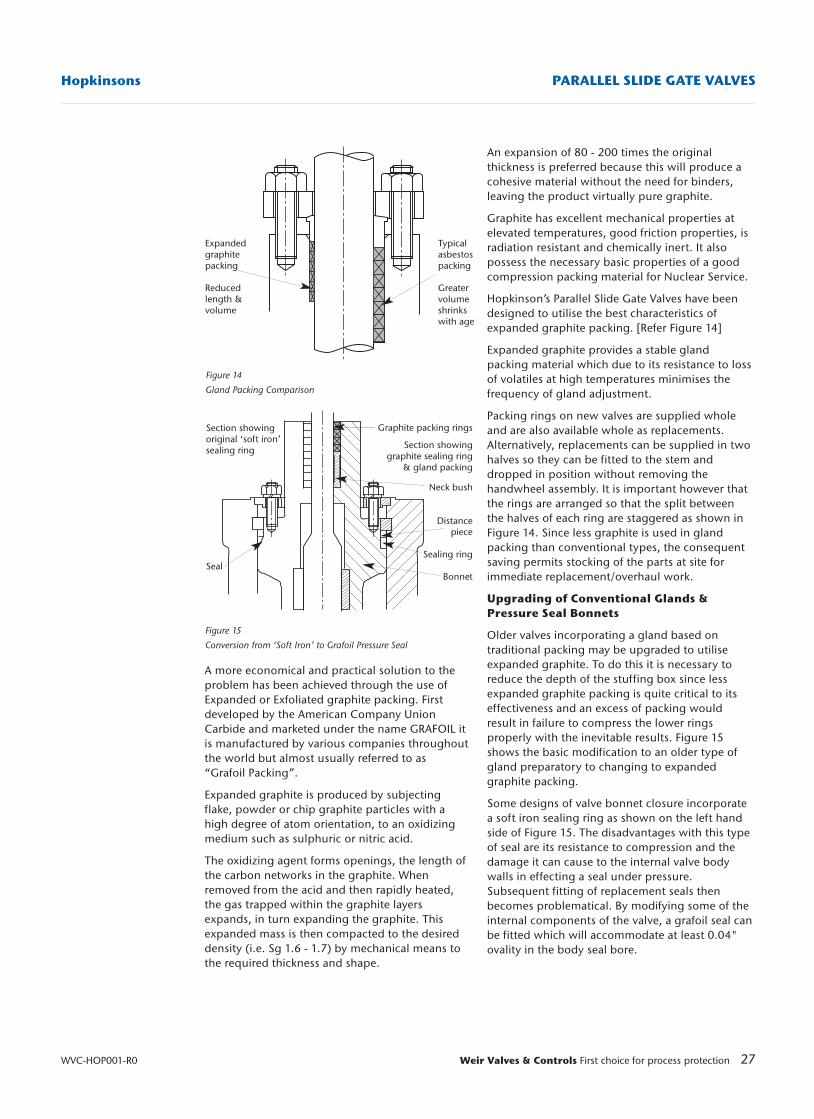
Figure 14
Gland Packing Comparison
Figure 15
Conversion from ‘Soft Iron’ to Grafoil Pressure Seal
Expandedgraphitepacking
Reduced length &volume
Typicalasbestospacking
Greatervolumeshrinkswith age
Section showingoriginal ‘soft iron’sealing ring
Seal
Graphite packing rings
Section showinggraphite sealing ring
& gland packing
Neck bush
Distancepiece
Sealing ring
Bonnet
An expansion of 80 - 200 times the originalthickness is preferred because this will produce acohesive material without the need for binders,leaving the product virtually pure graphite.
Graphite has excellent mechanical properties atelevated temperatures, good friction properties, isradiation resistant and chemically inert. It alsopossess the necessary basic properties of a goodcompression packing material for Nuclear Service.
Hopkinson’s Parallel Slide Gate Valves have beendesigned to utilise the best characteristics ofexpanded graphite packing. [Refer Figure 14]
Expanded graphite provides a stable glandpacking material which due to its resistance to lossof volatiles at high temperatures minimises thefrequency of gland adjustment.
Packing rings on new valves are supplied wholeand are also available whole as replacements.Alternatively, replacements can be supplied in twohalves so they can be fitted to the stem anddropped in position without removing thehandwheel assembly. It is important however thatthe rings are arranged so that the split betweenthe halves of each ring are staggered as shown inFigure 14. Since less graphite is used in glandpacking than conventional types, the consequentsaving permits stocking of the parts at site forimmediate replacement/overhaul work.
Upgrading of Conventional Glands &Pressure Seal Bonnets
Older valves incorporating a gland based ontraditional packing may be upgraded to utiliseexpanded graphite. To do this it is necessary toreduce the depth of the stuffing box since lessexpanded graphite packing is quite critical to itseffectiveness and an excess of packing wouldresult in failure to compress the lower ringsproperly with the inevitable results. Figure 15shows the basic modification to an older type ofgland preparatory to changing to expandedgraphite packing.
Some designs of valve bonnet closure incorporatea soft iron sealing ring as shown on the left handside of Figure 15. The disadvantages with this typeof seal are its resistance to compression and thedamage it can cause to the internal valve bodywalls in effecting a seal under pressure.Subsequent fitting of replacement seals thenbecomes problematical. By modifying some of theinternal components of the valve, a grafoil seal canbe fitted which will accommodate at least 0.04"ovality in the body seal bore.
A more economical and practical solution to theproblem has been achieved through the use ofExpanded or Exfoliated graphite packing. Firstdeveloped by the American Company UnionCarbide and marketed under the name GRAFOIL itis manufactured by various companies throughoutthe world but almost usually referred to as“Grafoil Packing”.
Expanded graphite is produced by subjectingflake, powder or chip graphite particles with ahigh degree of atom orientation, to an oxidizingmedium such as sulphuric or nitric acid.
The oxidizing agent forms openings, the length ofthe carbon networks in the graphite. Whenremoved from the acid and then rapidly heated,the gas trapped within the graphite layersexpands, in turn expanding the graphite. Thisexpanded mass is then compacted to the desireddensity (i.e. Sg 1.6 - 1.7) by mechanical means tothe required thickness and shape.
28 Weir Valves & Controls First choice for process protection WVC-HOP001-R0
HopkinsonsPARALLEL SLIDE GATE VALVES
Figure 19
Pressure Seal Bonnet
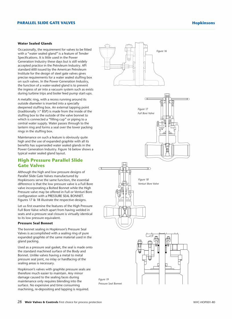
Water Sealed Glands
Occasionally, the requirement for valves to be fittedwith a “water sealed gland” is a feature of TenderSpecifications. It is little used in the PowerGeneration Industry these days but is still widelyaccepted practice in the Petroleum Industry. APIstandard 600 issued by the American PetroleumInstitute for the design of steel gate valves givesprecise requirements for a water sealed stuffing boxon such valves. In the Power Generation Industry,the function of a water-sealed gland is to preventthe ingress of air into a vacuum system such as existsduring turbine trips and boiler feed pump start-ups.
A metallic ring, with a recess running around itsoutside diameter is inserted into a speciallydeepened stuffing box. An external tapping point(traditionally 1⁄4" BSP) is made from the inside of thestuffing box to the outside of the valve bonnet towhich is connected a “filling cup” or piping to acentral water supply. Water passes through to thelantern ring and forms a seal over the lower packingrings in the stuffing box.
Maintenance on such a feature is obviously quitehigh and the use of expanded graphite with all itsbenefits has superseded water sealed glands in thePower Generation Industry. Figure 16 below shows atypical water sealed gland layout.
High Pressure Parallel SlideGate ValvesAlthough the high and low pressure designs ofParallel Slide Gate Valves manufactured byHopkinsons serve the same function, the essentialdifference is that the low pressure valve is a Full Borevalve incorporating a Bolted Bonnet while the HighPressure valve may be offered in Full or Venturi Boreconfiguration with a PRESSURE SEAL BONNET.Figures 17 & 18 illustrate the respective designs.
Let us first examine the features of the High PressureFull Bore Valve which apart from having welded inseats and a pressure seal closure is virtually identicalto its low pressure equivalent.
Pressure Seal Bonnet
The bonnet sealing in Hopkinson’s Pressure SealValves is accomplished with a sealing ring of pureexpanded graphite of the same material used in thegland packing.
Used as a pressure seal gasket, the seal is made ontothe standard machined surface of the Body andBonnet. Unlike valves having a metal to metalpressure seal joint, no inlay or hardfacing of thesealing areas is necessary.
Hopkinson’s valves with graphite pressure seals aretherefore much easier to maintain. Any minordamage caused to the sealing faces duringmaintenance only requires blending into thesurface. No expensive and time consumingmachining, re-depositing and lapping is required.
Figure 16
Figure 17
Full Bore Valve
Figure 18
Venturi Bore Valve
29Weir Valves & Controls First choice for process protection
Hopkinsons PARALLEL SLIDE GATE VALVES
WVC-HOP001-R0
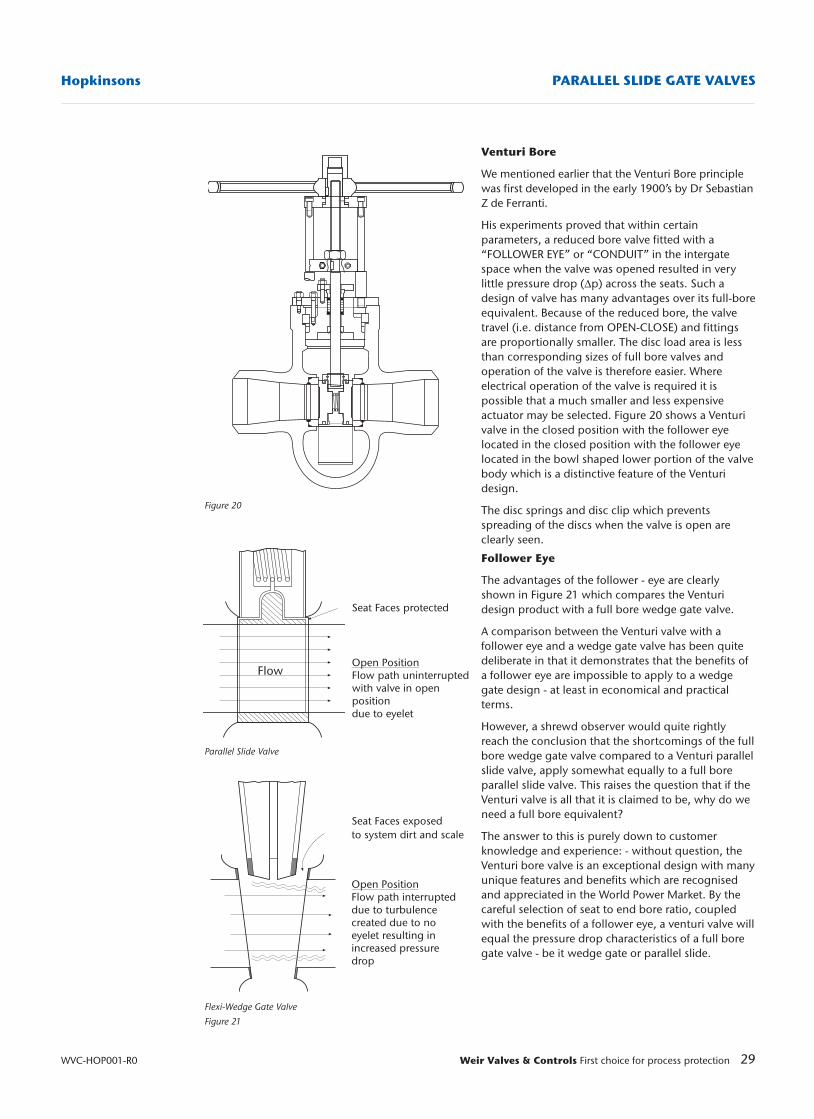
Figure 20
Parallel Slide Valve
Flexi-Wedge Gate Valve
Figure 21
Seat Faces protected
Open PositionFlow path uninterruptedwith valve in openpositiondue to eyelet
Flow
Seat Faces exposed to system dirt and scale
Open PositionFlow path interrupteddue to turbulencecreated due to noeyelet resulting inincreased pressuredrop
Venturi Bore
We mentioned earlier that the Venturi Bore principlewas first developed in the early 1900’s by Dr SebastianZ de Ferranti.
His experiments proved that within certainparameters, a reduced bore valve fitted with a“FOLLOWER EYE” or “CONDUIT” in the intergatespace when the valve was opened resulted in verylittle pressure drop (∆p) across the seats. Such adesign of valve has many advantages over its full-boreequivalent. Because of the reduced bore, the valvetravel (i.e. distance from OPEN-CLOSE) and fittingsare proportionally smaller. The disc load area is lessthan corresponding sizes of full bore valves andoperation of the valve is therefore easier. Whereelectrical operation of the valve is required it ispossible that a much smaller and less expensiveactuator may be selected. Figure 20 shows a Venturivalve in the closed position with the follower eyelocated in the closed position with the follower eyelocated in the bowl shaped lower portion of the valvebody which is a distinctive feature of the Venturidesign.
The disc springs and disc clip which preventsspreading of the discs when the valve is open areclearly seen.
Follower Eye
The advantages of the follower - eye are clearlyshown in Figure 21 which compares the Venturidesign product with a full bore wedge gate valve.
A comparison between the Venturi valve with afollower eye and a wedge gate valve has been quitedeliberate in that it demonstrates that the benefits ofa follower eye are impossible to apply to a wedgegate design - at least in economical and practicalterms.
However, a shrewd observer would quite rightlyreach the conclusion that the shortcomings of the fullbore wedge gate valve compared to a Venturi parallelslide valve, apply somewhat equally to a full boreparallel slide valve. This raises the question that if theVenturi valve is all that it is claimed to be, why do weneed a full bore equivalent?
The answer to this is purely down to customerknowledge and experience: - without question, theVenturi bore valve is an exceptional design with manyunique features and benefits which are recognisedand appreciated in the World Power Market. By thecareful selection of seat to end bore ratio, coupledwith the benefits of a follower eye, a venturi valve willequal the pressure drop characteristics of a full boregate valve - be it wedge gate or parallel slide.
30 Weir Valves & Controls First choice for process protection WVC-HOP001-R0
HopkinsonsPARALLEL SLIDE GATE VALVES
These primary service ratings were the permissibleworking pressures at a particular temperature.
The first deviation from this practice was in 1964when the manufacturers Standardisation Society ofthe valve and fittings industry (MSS) publishedStandard Practice SP66 covering pressuretemperature ratings of steel butt-weld end valves.The ANSI B16 committee set up a sub-committee tostudy the general subject of pressure temperatureratings and to develop rational criteria for suchratings.
ANSI B16.34 standard was the outcome of thesestudies and the 1973 version was issued to cover steelbutt welding end valves only. The SP66 type ratingswere included as ‘Special Class’. Flanged valves werestill included in ANSI B16.5 along with flanges.
A revision was issued in 1977 and another, thecurrent one, in 1996 with amendments in 1998. Thislatest edition covers flanged and butt welding endvalves in steel, nickel alloy and other special alloys. Inorder to cover flanged valves, rating tables have to beincluded for 150, 300, 600, 900, 1500 and 2500.
Since butt-welding end valves are not constrained bythe flange ratings, provision was made forintermediate ratings, which can be any class withinthe limits of the standard.
Analysis of market requirements shows that thecustomary (flange) ratings are not always aneconomic solution to the pressure temperaturerequirements. For example a 2500 class valve oftenfalls short of the requirements for main steam designconditions associated with large utility boilers.
If a 2500 class will not satisfy the requirements ofpressure and temperature the next standard rating is4500 class. Except for small sizes, the adoption of4500 class is not practical or economic. This can beillustrated by taking an example of a valve having a16" end bore.
Minimum wall thickness ‘tm’ for 2500 class isapprox. 5 1⁄2 ".
Minimum wall thickness ‘tm’ for 4500 class isapprox. 12 1⁄2 ".
Not only would the 4500 class valve be very expensivebut also there would be the practical problems ofsupport, unacceptable thermal gradients across thethick sections and the associated stress etc.
Many feed water applications require valves in excessof 1500 class and yet the required pressure-temperature rating is well short of 2500 class.
As stated earlier, provision is made in ASME B16.34for intermediate ratings (referred to as interpolatedratings in earlier editions). To quote the standard: - “Abutt welding end valve may be assigned anintermediate rating or class, either Standard or Special,providing all requirements of this standard are met”.
However, whilst the Venturi design can represent asignificant market advantage, the product may onlybe offered under the following conditions: -
(a) Steam velocities through the seat area must not exceed 90m/sec (Saturated Steam) 180m/sec (Superheated Steam).
(b) Water velocities through the seat area must not exceed 15m/sec.
Full bore valves i.e. valves without a follower eye arerestricted to the following:-
(a) Steam velocities through the seat area must not exceed 66m/sec (Saturated Steam)130 m/sec (Superheated Steam)
(b) Water velocities through the seat area must not exceed 12m/sec.
The following formula should be used in determiningseat velocities and pressure drop.
Velocity in ft/sec = flow in Ib/hr x Sp Vol in cu.ft/Ib19.635 x (seat bore in inches)2
Pressure Drop = ‘K’ x (pipe velocity in ft/sec)2
9274 x Sp vol.in cu.ft/Ib
It should also be remembered that although the seatbore can be adjusted to suit a given set of designconditions for a specific pipe size, the nominal endbore size of the Venturi valve remains unchanged andcompatible with the customers designated pipingand butt weld end size. Even so, the benefits of aVenturi style Parallel Slide Valve are not always readilyunderstood or accepted by customers - even after themost strenuous sales efforts coupled with technicalsupport. This occurs most often in areas of the world,which have been exposed to American PowerTechnology and Consultants. Similarly EuropeanContractors, particularly German and Italian havevery conservative attitudes towards seat velocities andin spite of our own reassurances have rejected theproduct.
In such circumstances, it is more sensible for theSalesperson not to pursue the issue but offer a fullbore Parallel Slide Valve. The sales effort can then bedirected towards the benefit of the Parallel Slide Valveover the Wedge Gate, keeping the Venturi issue out ofthe equation. There are non-so blind as those who donot wish to see!
Product Ratings
The current range of High Pressure Parallel SlideValves comply with the design requirements of ASMEB16.34 in 600# 1000# 1700# 2350# AND 3100#Class Ratings. With the exception of the 600# valve,the other high-pressure valve ratings do not fall intocustomary defined categories.
The customary valve ratings in ASME (formerly ANSI)standards have been 300, 400, 600, 900, 1500, 2500& 4500 classes. Up to 2500 class these have followedflange standards and were originally ‘Primary ServiceRatings’.
31Weir Valves & Controls First choice for process protection
Hopkinsons PARALLEL SLIDE GATE VALVES
WVC-HOP001-R0
Figure 22
Outlet disc
Flow path
Outlet seat
On this basis Hopkinsons have adopted pressure-temperature ratings as standard, 1000 class, 1700class, 2350 class and 3100 class. These replace thecustomary 900 class, 1500 class and 2500 class.Higher ratings are available as required.
The main point to remember is that theseintermediate rated valves conform to therequirement of B16.34. Standard or Special asappropriate, without any qualification.
A valve designed to meet 1000 class would only berated as 900 class standard if it had 900 classflanges. All flanged valves would be limited to theflange rating and in WC6 and WC9 would have anupper temperature limit of 1000˚F.
When the required rating is 600 class or less, theadvantages of intermediate ratings become marginaland tend not to be adopted by any company.
Relationship Between Nominal Pipesize andValve Seat Diameter (ASME B.16.34)
One of the most frequently misunderstood aspectsof he ASME design code and its intent, is theconfusion some customers have in regard to theVenturi Parallel Slide Gate Valve not meetingminimum flow path criteria.
The paragraph in ASME B.16.34 to which they referis 6.1.2 and states:- “For the purpose of determiningthe wall thickness tm, the inside diameter d is takenas the minimum diameter of the flow passage butnot less than 90% of the basic inside diameter at thevalve end . . .”
It is not unusual for some customers to mistakenlyinterpret this paragraph as meaning a valve seatbore should not be less than 90% of the valve endbore.
Let us be quite clear on this matter. ASME B.16.34makes no restriction whatsoever on seat bore. Thepurpose of clause 6.1.2 when used in conjunctionwith table A1 of the said code is for determining theminimum valve wall thickness tm. In determiningthe minimum thickness tm, the diameter used mustnot be less than 90% of the end bore. This 90%valve only applies to the determination of tm –nothing more.
Market ApplicationsPower Generation Industry
The many applications of both Low and HighPressure Parallel Slide Valves can be clearly seen inthe schematic layouts of the Combined Cycle andFossil Fuel Power Plants accompanying this text.These are purely isolation functions but there areoccasions during start up of the plant where it isnecessary to have a degree of regulation through thevalve.
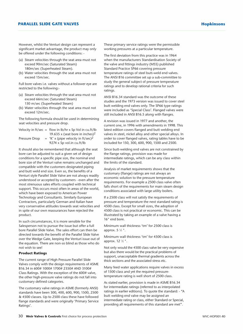
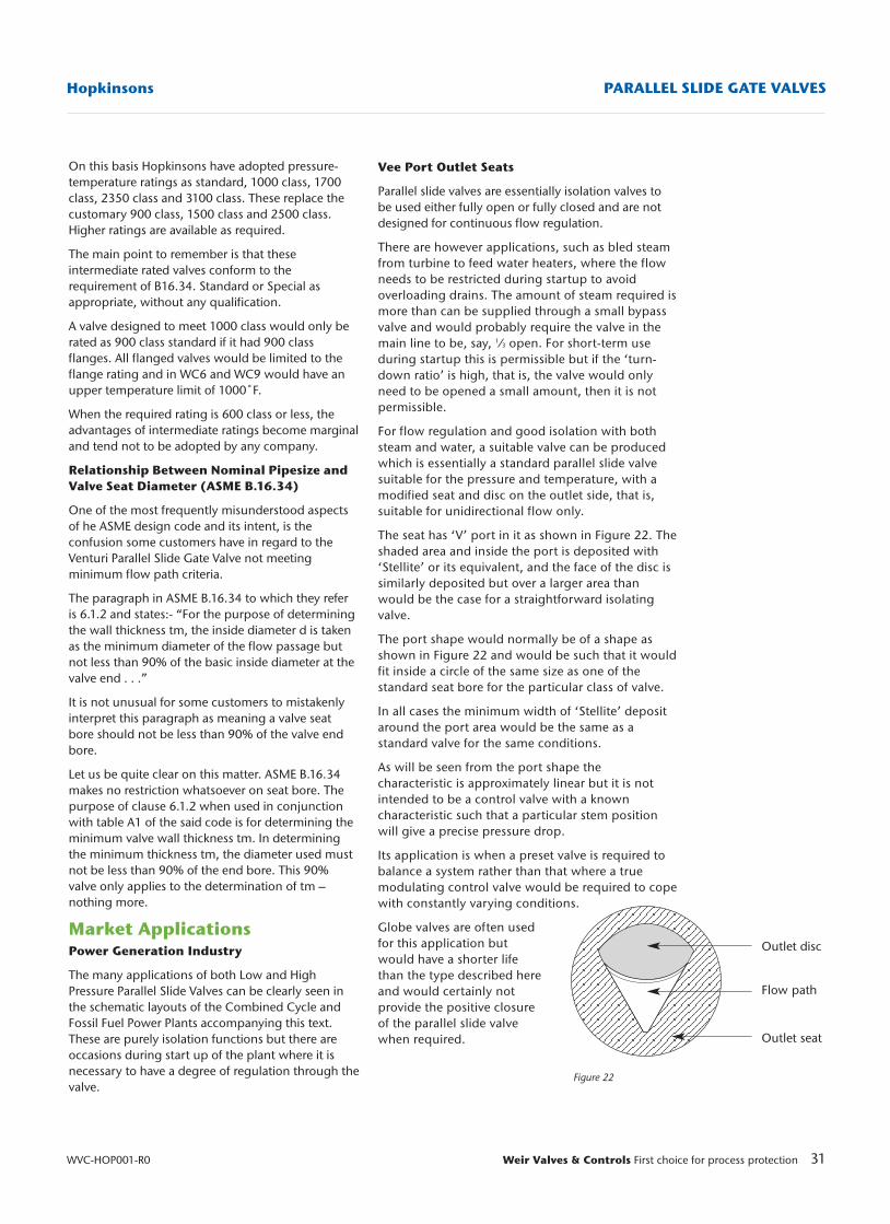
Vee Port Outlet Seats
Parallel slide valves are essentially isolation valves tobe used either fully open or fully closed and are notdesigned for continuous flow regulation.
There are however applications, such as bled steamfrom turbine to feed water heaters, where the flowneeds to be restricted during startup to avoidoverloading drains. The amount of steam required ismore than can be supplied through a small bypassvalve and would probably require the valve in themain line to be, say, 1⁄3 open. For short-term useduring startup this is permissible but if the ‘turn-down ratio’ is high, that is, the valve would onlyneed to be opened a small amount, then it is notpermissible.
For flow regulation and good isolation with bothsteam and water, a suitable valve can be producedwhich is essentially a standard parallel slide valvesuitable for the pressure and temperature, with amodified seat and disc on the outlet side, that is,suitable for unidirectional flow only.
The seat has ‘V’ port in it as shown in Figure 22. Theshaded area and inside the port is deposited with‘Stellite’ or its equivalent, and the face of the disc issimilarly deposited but over a larger area thanwould be the case for a straightforward isolatingvalve.
The port shape would normally be of a shape asshown in Figure 22 and would be such that it wouldfit inside a circle of the same size as one of thestandard seat bore for the particular class of valve.
In all cases the minimum width of ‘Stellite’ depositaround the port area would be the same as astandard valve for the same conditions.
As will be seen from the port shape thecharacteristic is approximately linear but it is notintended to be a control valve with a knowncharacteristic such that a particular stem positionwill give a precise pressure drop.
Its application is when a preset valve is required tobalance a system rather than that where a truemodulating control valve would be required to copewith constantly varying conditions.
Globe valves are often usedfor this application butwould have a shorter lifethan the type described hereand would certainly notprovide the positive closureof the parallel slide valvewhen required.
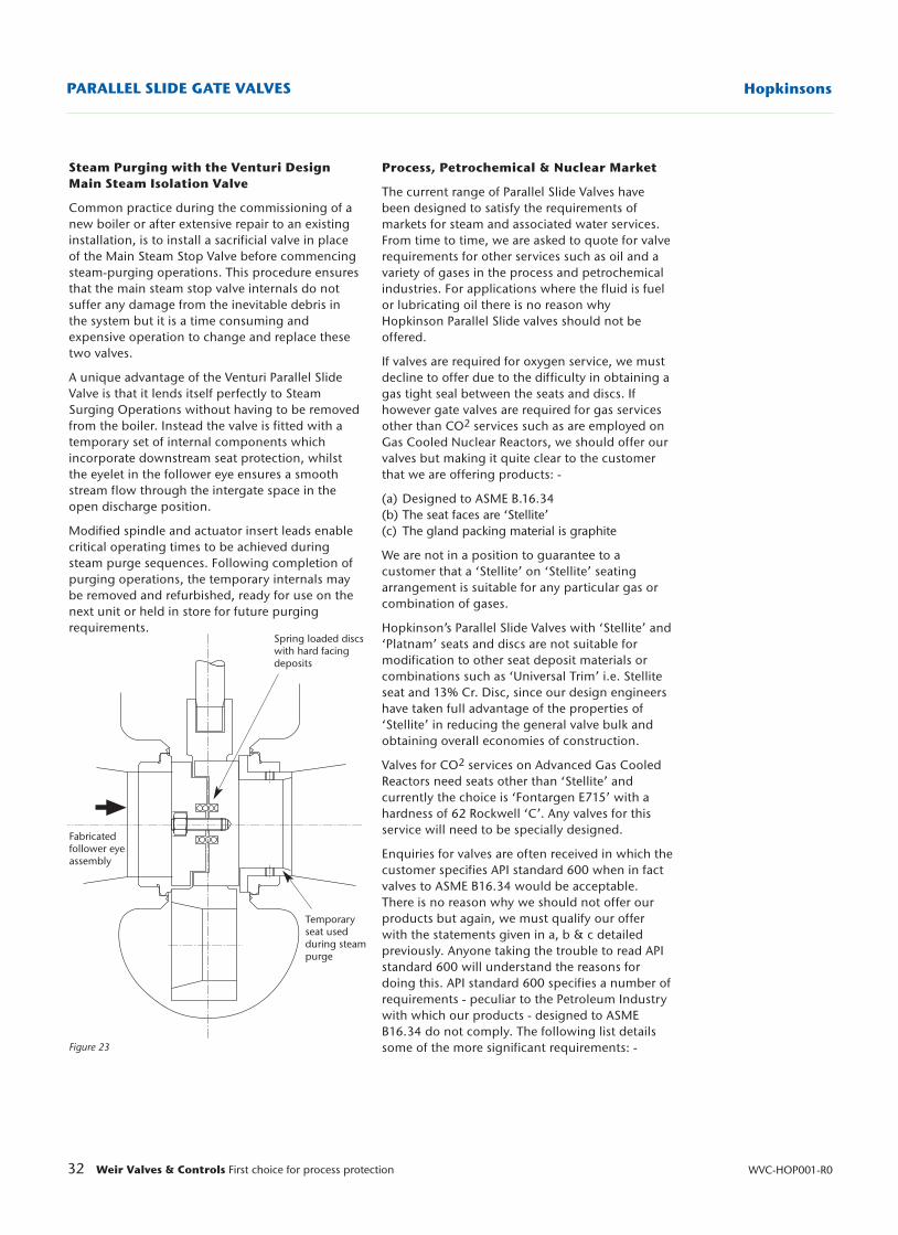
32 Weir Valves & Controls First choice for process protection WVC-HOP001-R0
HopkinsonsPARALLEL SLIDE GATE VALVES
Figure 23
Spring loaded discswith hard facingdeposits
Temporary seat used during steampurge
Fabricated follower eyeassembly
Steam Purging with the Venturi DesignMain Steam Isolation Valve
Common practice during the commissioning of anew boiler or after extensive repair to an existinginstallation, is to install a sacrificial valve in placeof the Main Steam Stop Valve before commencingsteam-purging operations. This procedure ensuresthat the main steam stop valve internals do notsuffer any damage from the inevitable debris inthe system but it is a time consuming andexpensive operation to change and replace thesetwo valves.
A unique advantage of the Venturi Parallel SlideValve is that it lends itself perfectly to SteamSurging Operations without having to be removedfrom the boiler. Instead the valve is fitted with atemporary set of internal components whichincorporate downstream seat protection, whilstthe eyelet in the follower eye ensures a smoothstream flow through the intergate space in theopen discharge position.
Modified spindle and actuator insert leads enablecritical operating times to be achieved duringsteam purge sequences. Following completion ofpurging operations, the temporary internals maybe removed and refurbished, ready for use on thenext unit or held in store for future purgingrequirements.
Process, Petrochemical & Nuclear Market
The current range of Parallel Slide Valves havebeen designed to satisfy the requirements ofmarkets for steam and associated water services.From time to time, we are asked to quote for valverequirements for other services such as oil and avariety of gases in the process and petrochemicalindustries. For applications where the fluid is fuelor lubricating oil there is no reason whyHopkinson Parallel Slide valves should not beoffered.
If valves are required for oxygen service, we mustdecline to offer due to the difficulty in obtaining agas tight seal between the seats and discs. Ifhowever gate valves are required for gas servicesother than CO2 services such as are employed onGas Cooled Nuclear Reactors, we should offer ourvalves but making it quite clear to the customerthat we are offering products: -
(a) Designed to ASME B.16.34(b) The seat faces are ‘Stellite’(c) The gland packing material is graphite
We are not in a position to guarantee to acustomer that a ‘Stellite’ on ‘Stellite’ seatingarrangement is suitable for any particular gas orcombination of gases.
Hopkinson’s Parallel Slide Valves with ‘Stellite’ and‘Platnam’ seats and discs are not suitable formodification to other seat deposit materials orcombinations such as ‘Universal Trim’ i.e. Stelliteseat and 13% Cr. Disc, since our design engineershave taken full advantage of the properties of‘Stellite’ in reducing the general valve bulk andobtaining overall economies of construction.
Valves for CO2 services on Advanced Gas CooledReactors need seats other than ‘Stellite’ andcurrently the choice is ‘Fontargen E715’ with ahardness of 62 Rockwell ‘C’. Any valves for thisservice will need to be specially designed.
Enquiries for valves are often received in which thecustomer specifies API standard 600 when in factvalves to ASME B16.34 would be acceptable.There is no reason why we should not offer ourproducts but again, we must qualify our offerwith the statements given in a, b & c detailedpreviously. Anyone taking the trouble to read APIstandard 600 will understand the reasons fordoing this. API standard 600 specifies a number ofrequirements - peculiar to the Petroleum Industrywith which our products - designed to ASMEB16.34 do not comply. The following list detailssome of the more significant requirements: -
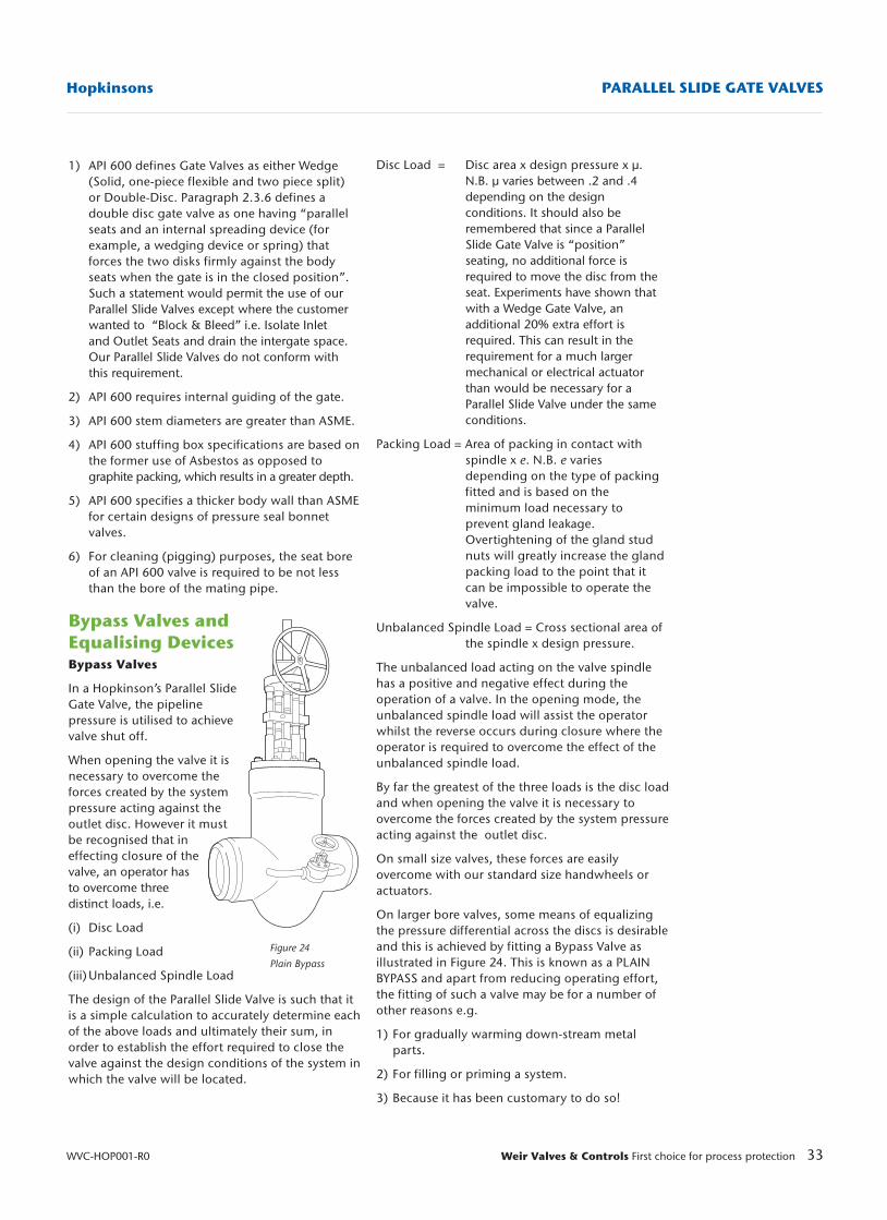
1) API 600 defines Gate Valves as either Wedge (Solid, one-piece flexible and two piece split) or Double-Disc. Paragraph 2.3.6 defines a double disc gate valve as one having “parallel seats and an internal spreading device (for example, a wedging device or spring) that forces the two disks firmly against the body seats when the gate is in the closed position”.Such a statement would permit the use of our Parallel Slide Valves except where the customer wanted to “Block & Bleed” i.e. Isolate Inlet and Outlet Seats and drain the intergate space. Our Parallel Slide Valves do not conform with this requirement.
2) API 600 requires internal guiding of the gate.
3) API 600 stem diameters are greater than ASME.
4) API 600 stuffing box specifications are based onthe former use of Asbestos as opposed to graphite packing, which results in a greater depth.
5) API 600 specifies a thicker body wall than ASMEfor certain designs of pressure seal bonnet valves.
6) For cleaning (pigging) purposes, the seat bore of an API 600 valve is required to be not less than the bore of the mating pipe.
Bypass Valves andEqualising DevicesBypass Valves
In a Hopkinson’s Parallel SlideGate Valve, the pipelinepressure is utilised to achievevalve shut off.
When opening the valve it isnecessary to overcome theforces created by the systempressure acting against theoutlet disc. However it mustbe recognised that ineffecting closure of the valve, an operator has to overcome threedistinct loads, i.e.
(i) Disc Load
(ii) Packing Load
(iii) Unbalanced Spindle Load
The design of the Parallel Slide Valve is such that itis a simple calculation to accurately determine eachof the above loads and ultimately their sum, inorder to establish the effort required to close thevalve against the design conditions of the system inwhich the valve will be located.
33Weir Valves & Controls First choice for process protection
Hopkinsons PARALLEL SLIDE GATE VALVES
WVC-HOP001-R0
Figure 24
Plain Bypass
Disc Load = Disc area x design pressure x µ.N.B. µ varies between .2 and .4 depending on the design conditions. It should also be remembered that since a Parallel Slide Gate Valve is “position” seating, no additional force is required to move the disc from the seat. Experiments have shown that with a Wedge Gate Valve, an additional 20% extra effort is required. This can result in the requirement for a much largermechanical or electrical actuator than would be necessary for a Parallel Slide Valve under the same conditions.
Packing Load = Area of packing in contact with spindle x e. N.B. e varies depending on the type of packing fitted and is based on the minimum load necessary to prevent gland leakage. Overtightening of the gland stud nuts will greatly increase the gland packing load to the point that it can be impossible to operate the valve.
Unbalanced Spindle Load = Cross sectional area of the spindle x design pressure.
The unbalanced load acting on the valve spindlehas a positive and negative effect during theoperation of a valve. In the opening mode, theunbalanced spindle load will assist the operatorwhilst the reverse occurs during closure where theoperator is required to overcome the effect of theunbalanced spindle load.
By far the greatest of the three loads is the disc loadand when opening the valve it is necessary toovercome the forces created by the system pressureacting against the outlet disc.
On small size valves, these forces are easilyovercome with our standard size handwheels oractuators.
On larger bore valves, some means of equalizingthe pressure differential across the discs is desirableand this is achieved by fitting a Bypass Valve asillustrated in Figure 24. This is known as a PLAINBYPASS and apart from reducing operating effort,the fitting of such a valve may be for a number ofother reasons e.g.
1) For gradually warming down-stream metal parts.
2) For filling or priming a system.
3) Because it has been customary to do so!
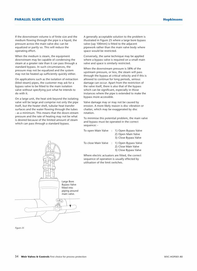
Large BoreBypass Valvefitted intopiping aroundmain valve.
34 Weir Valves & Controls First choice for process protection WVC-HOP001-R0
HopkinsonsPARALLEL SLIDE GATE VALVES
Figure 25
If the downstream volume is of finite size and themedium flowing through the pipe is a liquid, thepressure across the main valve disc can beequalized or partly so. This will reduce theoperating effort.
When the medium is steam, the equipmentdownstream may be capable of condensing thesteam at a greater rate than it can pass through astandard bypass. In such circumstances, thepressure may not be equalized and the systemmay not be heated up sufficiently quickly either.
On applications such as the isolation of extraction(bled steam) pipes, the customer may ask for abypass valve to be fitted to the main isolationvalve without specifying just what he intends todo with it.
On a large unit, the heat sink beyond the isolatingvalve will be large and comprise not only the pipeitself, but the heater shell, tubular heat transfersurfaces and the water flowing through the tubes- as a minimum. This means that the down-streampressure and the rate of heating may not be whatis desired because of the limited amount of steamwhich can pass through a standard bypass.
A generally acceptable solution to the problem isillustrated in Figure 25 where a large bore bypassvalve (say 100mm) is fitted to the adjacentpipework rather than the main valve body wherespace would be restricted.
Conversely, the same technique may be appliedwhere a bypass valve is required on a small mainvalve and space is similarly restricted.
When the downstream pressure is 58% of theupstream pressure, or less, the steam will passthrough the bypass at critical velocity and if this isallowed to continue for long periods, seriousdamage can occur. Apart from the restriction ofthe valve itself, there is also that of the bypasswhich can be significant, especially in thoseinstances where the pipe is extended to make thebypass more accessible.
Valve damage may or may not be caused byerosion. A more likely reason is disc vibration orchatter, which may be exaggerated by discrotation.
To minimise this potential problem, the main valveand bypass must be operated in the correctsequence: -
To open Main Valve : 1) Open Bypass Valve2) Open Main Valve3) Close Bypass Valve
To close Main Valve : 1) Open Bypass Valve2) Close Main Valve3) Close Bypass Valve
Where electric actuators are fitted, the correctsequence of operation is usually effected byutilisation of the limit switches.
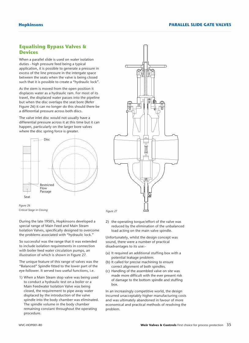
35Weir Valves & Controls First choice for process protection
Hopkinsons PARALLEL SLIDE GATE VALVES
WVC-HOP001-R0
Equalising Bypass Valves &DevicesWhen a parallel slide is used on water isolationduties - high pressure feed being a typicalapplication, it is possible to generate a pressure inexcess of the line pressure in the intergate spacebetween the seats when the valve is being closedsuch that it is possible to create a “hydraulic lock”.
As the stem is moved from the open position itdisplaces water as a hydraulic ram. For most of itstravel, the displaced water passes into the pipelinebut when the disc overlaps the seat bore (ReferFigure 26) it can no longer do this should there bea differential pressure across both discs.
The valve inlet disc would not usually have adifferential pressure across it at this time but it canhappen, particularly on the larger bore valveswhere the disc spring force is greater.
During the late 1950’s, Hopkinsons developed aspecial range of Main Feed and Main SteamIsolation Valves, specifically designed to overcomethe problems associated with “hydraulic lock.”
So successful was the range that it was extendedto include isolation requirements in connectionwith boiler feed water circulation pumps, anillustration of which is shown in Figure 27.
The unique feature of this range of valves was the“Balanced” Spindle fitted to the lower part of theeye-follower. It served two useful functions, i.e.
1) When a Main Steam stop valve was being used to conduct a hydraulic test on a boiler or a Main Feedwater Isolation Valve was being closed, the requirement to pipe away water displaced by the introduction of the valve spindle into the body chamber was eliminated. The spindle volume in the body chamber remaining constant throughout the operating procedure.
Figure 26
Critical Stage in Closing Figure 27
RestrictedFlowPassage
2) the operating torque/effort of the valve was reduced by the elimination of the unbalanced load acting on the main valve spindle.
Unfortunately, whilst the design concept wassound, there were a number of practicaldisadvantages to its use:-
(a) It required an additional stuffing box with a potential leakage problem.
(b) It called for precise machining to ensure correct alignment of both spindles.
(c) Handling of the assembled valve on site was made more difficult with the ever present risk of damage to the bottom spindle and stuffing box.
In an increasingly competitive world, the designincurred unacceptably higher manufacturing costsand was ultimately abandoned in favour of moreeconomical and practical methods of resolving theproblem.
Disc
Seat
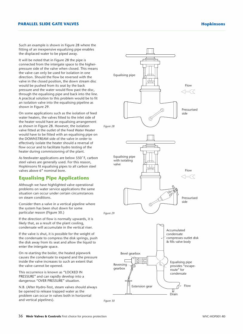
36 Weir Valves & Controls First choice for process protection WVC-HOP001-R0
HopkinsonsPARALLEL SLIDE GATE VALVES
Figure 28
Figure 29
Figure 30
Accumulatedcondensatecompresses outlet disk& fills valve body
Equalising pipe provides “escape-route” for condensate
Flow
Drain
Extension gear
Reversinggearbox
Bevel gearbox
Equalising pipewith isolatingvalve
Pressurisedside
Equalising pipe
Flow
Pressurisedside
Flow
Such an example is shown in Figure 28 where thefitting of an inexpensive equalizing pipe enablesthe displaced water to be piped away.
It will be noted that in Figure 28 the pipe isconnected from the intergate space to the higher-pressure side of the valve when closed. This meansthe valve can only be used for isolation in onedirection. Should the flow be reversed with thevalve in the closed position, the down stream discwould be pushed from its seat by the backpressure and the water would flow past the disc,through the equalising pipe and back into the line.A practical solution to this problem would be to fitan isolation valve into the equalising pipeline asshown in Figure 29.
On some applications such as the isolation of feedwater heaters, the valves fitted to the inlet side ofthe heater would have an equalising arrangementas shown in Figure 28. However, the isolationvalve fitted at the outlet of the Feed Water Heaterwould have to be fitted with an equalising pipe onthe DOWNSTREAM side of the valve in order toeffectively isolate the heater should a reversal offlow occur and to facilitate hydro testing of theheater during commissioning of the plant.
As feedwater applications are below 550˚F, carbonsteel valves are generally used. For this reason,Hopkinsons fit equalising pipes to all carbon steelvalves above 6” nominal bore.
Equalising Pipe Applications Although we have highlighted valve operationalproblems on water service applications the samesituation can occur under certain circumstanceson steam conditions.
Consider then a valve in a vertical pipeline wherethe system has been shut down for someparticular reason (Figure 30.)
If the direction of flow is normally upwards, it islikely that, as a result of the plant cooling,condensate will accumulate in the vertical riser.
If the valve is shut, it is possible for the weight ofthe condensate to compress the disk springs, pushthe disk away from its seat and allow the liquid toenter the intergate space.
On re-starting the boiler, the heated pipeworkcauses the condensate to expand and the pressureinside the valve increases to such an extent thatthe valve cannot be opened.
This occurrence is known as “LOCKED INPRESSURE” and can rapidly develop into adangerous “OVER PRESSURE” situation.
N.B. (After Hydro-Test, steam valves should alwaysbe opened to release trapped water as theproblem can occur in valves both in horizontaland vertical pipelines).
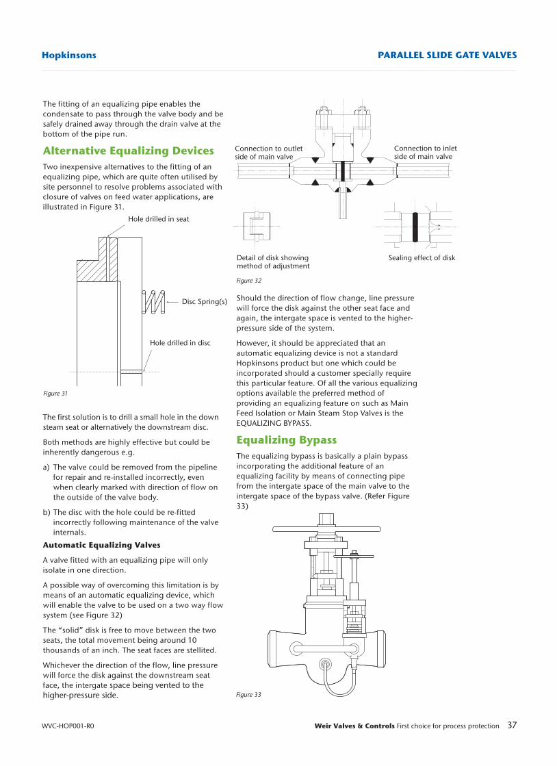
37Weir Valves & Controls First choice for process protection
Hopkinsons PARALLEL SLIDE GATE VALVES
WVC-HOP001-R0
The fitting of an equalizing pipe enables thecondensate to pass through the valve body and besafely drained away through the drain valve at thebottom of the pipe run.
Alternative Equalizing DevicesTwo inexpensive alternatives to the fitting of anequalizing pipe, which are quite often utilised bysite personnel to resolve problems associated withclosure of valves on feed water applications, areillustrated in Figure 31.
The first solution is to drill a small hole in the downsteam seat or alternatively the downstream disc.
Both methods are highly effective but could beinherently dangerous e.g.
a) The valve could be removed from the pipeline for repair and re-installed incorrectly, even when clearly marked with direction of flow on the outside of the valve body.
b) The disc with the hole could be re-fitted incorrectly following maintenance of the valve internals.
Automatic Equalizing Valves
A valve fitted with an equalizing pipe will onlyisolate in one direction.
A possible way of overcoming this limitation is bymeans of an automatic equalizing device, whichwill enable the valve to be used on a two way flowsystem (see Figure 32)
The “solid” disk is free to move between the twoseats, the total movement being around 10thousands of an inch. The seat faces are stellited.
Whichever the direction of the flow, line pressurewill force the disk against the downstream seatface, the intergate space being vented to thehigher-pressure side.
Figure 31
Hole drilled in seat
Hole drilled in disc
Figure 33
Figure 32
Connection to outletside of main valve
Connection to inletside of main valve
Detail of disk showingmethod of adjustment
Sealing effect of disk
Should the direction of flow change, line pressurewill force the disk against the other seat face andagain, the intergate space is vented to the higher-pressure side of the system.
However, it should be appreciated that anautomatic equalizing device is not a standardHopkinsons product but one which could beincorporated should a customer specially requirethis particular feature. Of all the various equalizingoptions available the preferred method ofproviding an equalizing feature on such as MainFeed Isolation or Main Steam Stop Valves is theEQUALIZING BYPASS.
Equalizing BypassThe equalizing bypass is basically a plain bypassincorporating the additional feature of anequalizing facility by means of connecting pipefrom the intergate space of the main valve to theintergate space of the bypass valve. (Refer Figure33)
Disc Spring(s)
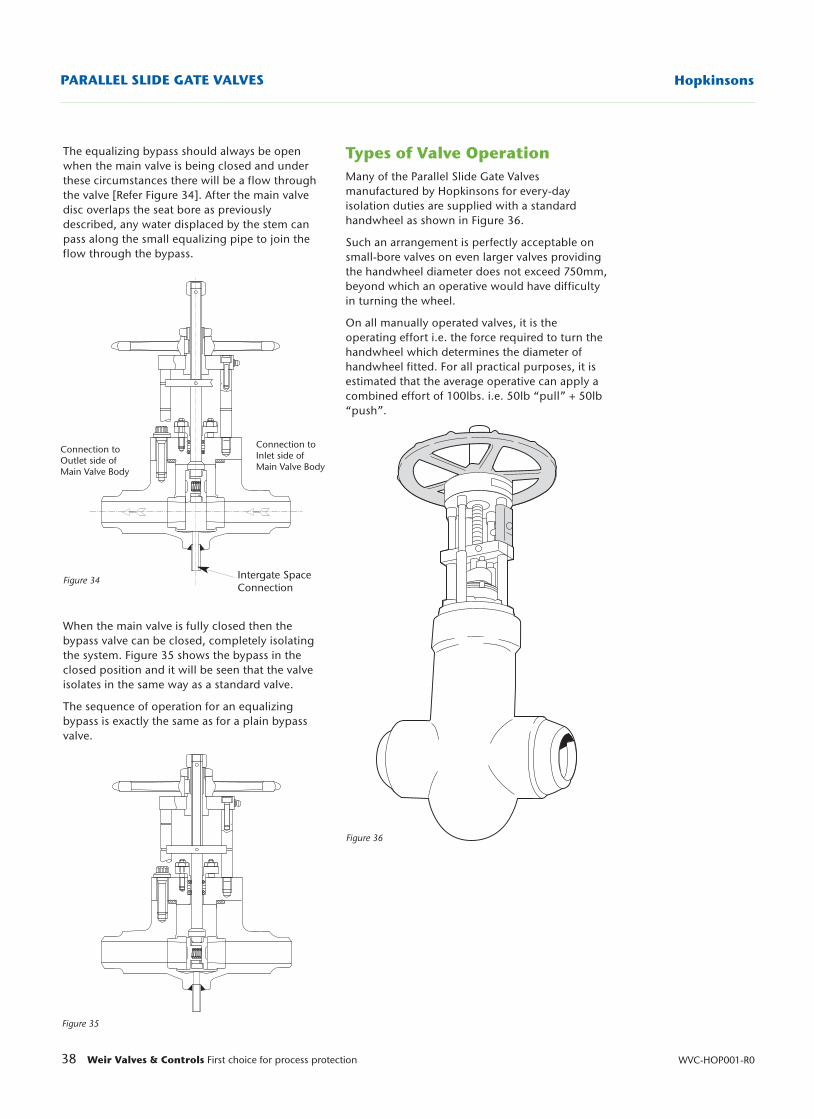
38 Weir Valves & Controls First choice for process protection WVC-HOP001-R0
HopkinsonsPARALLEL SLIDE GATE VALVES
Figure 34
Figure 35
Figure 36
The equalizing bypass should always be openwhen the main valve is being closed and underthese circumstances there will be a flow throughthe valve [Refer Figure 34]. After the main valvedisc overlaps the seat bore as previouslydescribed, any water displaced by the stem canpass along the small equalizing pipe to join theflow through the bypass.
When the main valve is fully closed then thebypass valve can be closed, completely isolatingthe system. Figure 35 shows the bypass in theclosed position and it will be seen that the valveisolates in the same way as a standard valve.
The sequence of operation for an equalizingbypass is exactly the same as for a plain bypassvalve.
Connection toOutlet side ofMain Valve Body
Connection toInlet side ofMain Valve Body
Intergate SpaceConnection
Types of Valve OperationMany of the Parallel Slide Gate Valvesmanufactured by Hopkinsons for every-dayisolation duties are supplied with a standardhandwheel as shown in Figure 36.
Such an arrangement is perfectly acceptable onsmall-bore valves on even larger valves providingthe handwheel diameter does not exceed 750mm,beyond which an operative would have difficultyin turning the wheel.
On all manually operated valves, it is theoperating effort i.e. the force required to turn thehandwheel which determines the diameter ofhandwheel fitted. For all practical purposes, it isestimated that the average operative can apply acombined effort of 100lbs. i.e. 50lb “pull” + 50lb“push”.
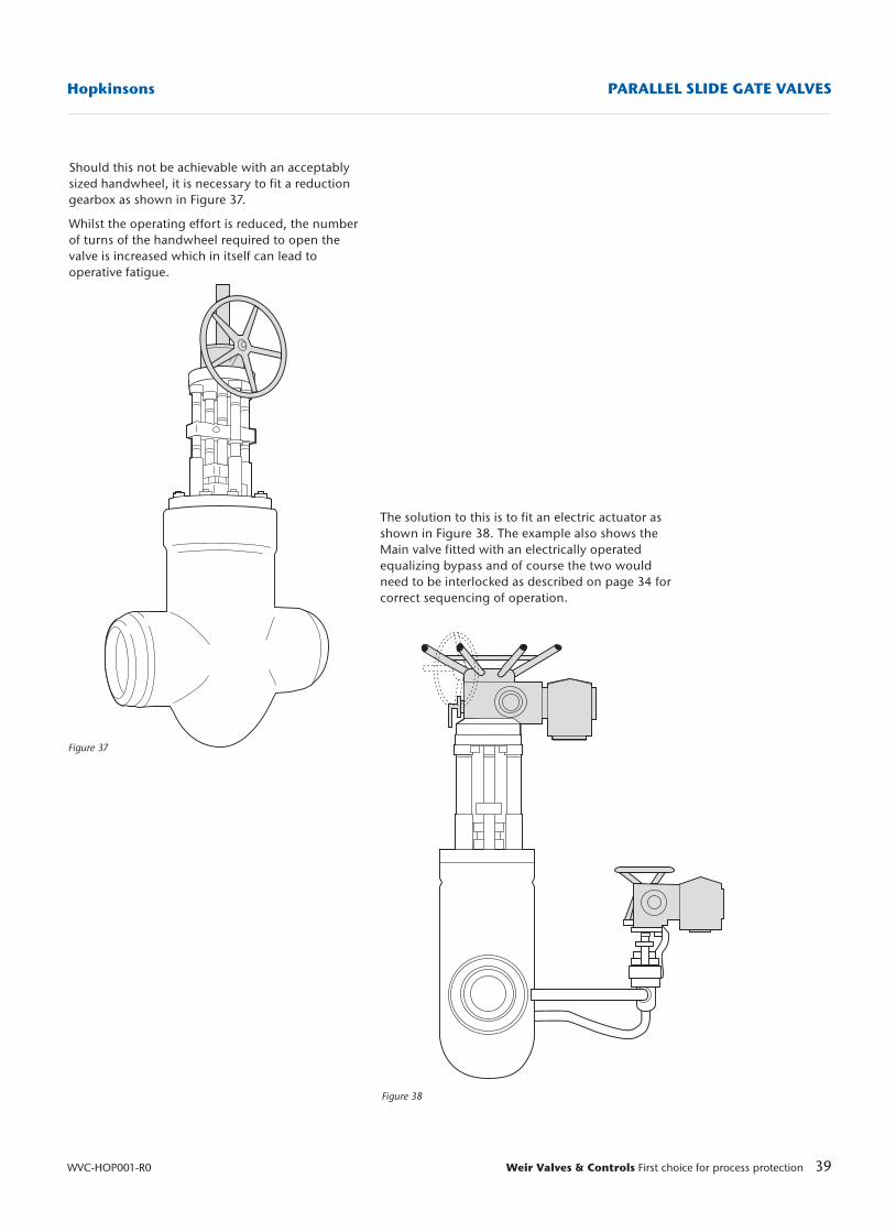
39Weir Valves & Controls First choice for process protection
Hopkinsons PARALLEL SLIDE GATE VALVES
WVC-HOP001-R0
Figure 37
Figure 38
The solution to this is to fit an electric actuator asshown in Figure 38. The example also shows theMain valve fitted with an electrically operatedequalizing bypass and of course the two wouldneed to be interlocked as described on page 34 forcorrect sequencing of operation.
Should this not be achievable with an acceptablysized handwheel, it is necessary to fit a reductiongearbox as shown in Figure 37.
Whilst the operating effort is reduced, the numberof turns of the handwheel required to open thevalve is increased which in itself can lead tooperative fatigue.
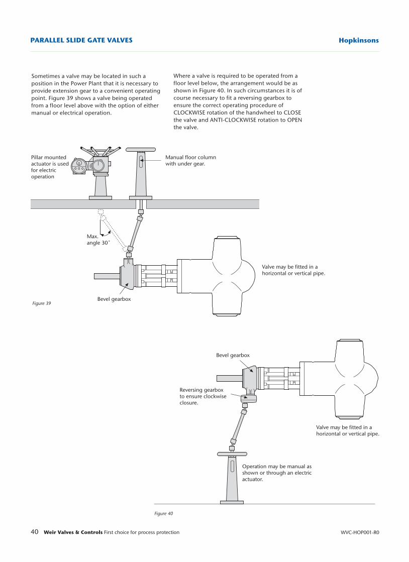
40 Weir Valves & Controls First choice for process protection WVC-HOP001-R0
HopkinsonsPARALLEL SLIDE GATE VALVES
Figure 39
Figure 40
Bevel gearbox
Reversing gearboxto ensure clockwiseclosure.
Valve may be fitted in ahorizontal or vertical pipe.
Operation may be manual as shown or through an electric actuator.
Bevel gearbox
Valve may be fitted in ahorizontal or vertical pipe.
Manual floor columnwith under gear.
Pillar mountedactuator is usedfor electricoperation
Max. angle 30˚
Sometimes a valve may be located in such aposition in the Power Plant that it is necessary toprovide extension gear to a convenient operatingpoint. Figure 39 shows a valve being operatedfrom a floor level above with the option of eithermanual or electrical operation.
Where a valve is required to be operated from afloor level below, the arrangement would be asshown in Figure 40. In such circumstances it is ofcourse necessary to fit a reversing gearbox toensure the correct operating procedure ofCLOCKWISE rotation of the handwheel to CLOSEthe valve and ANTI-CLOCKWISE rotation to OPENthe valve.
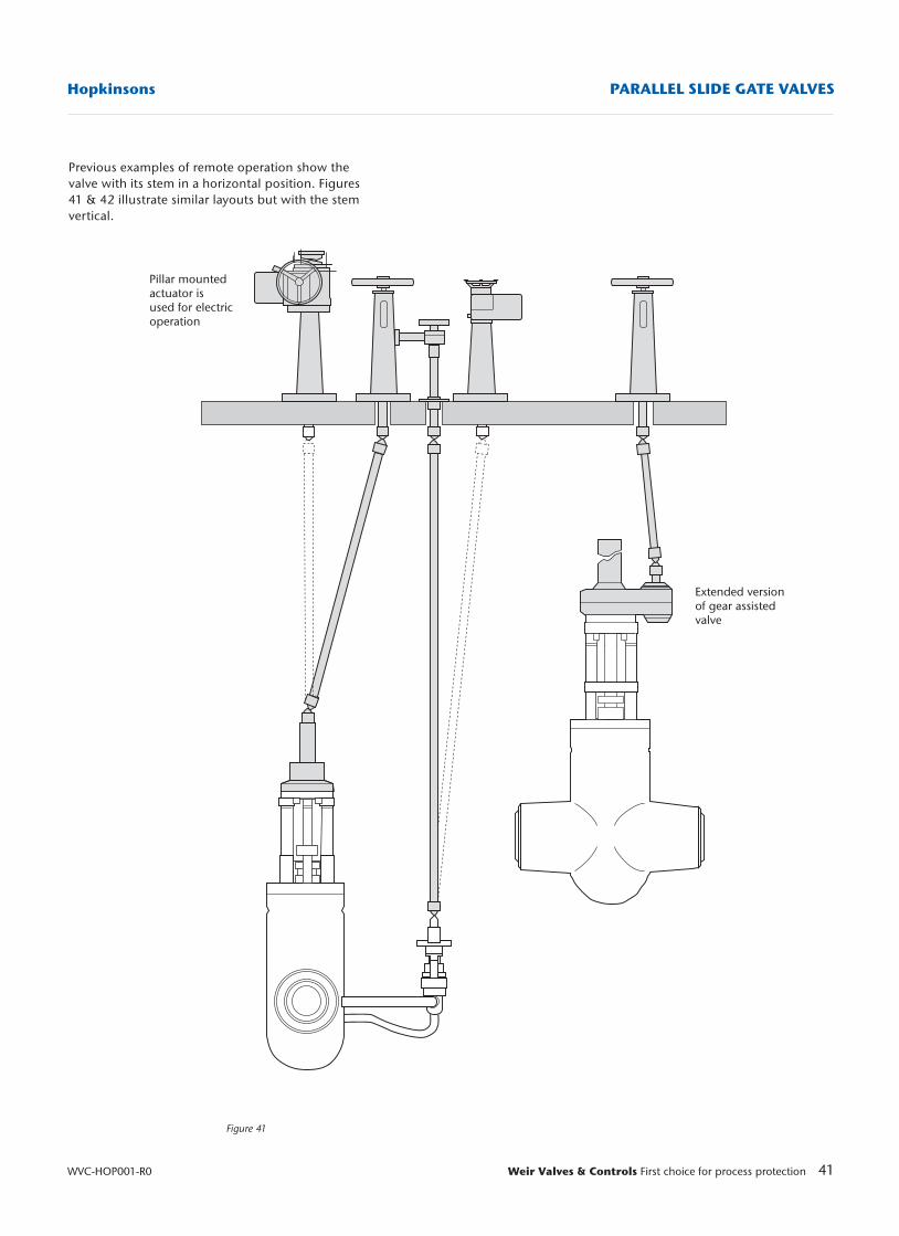
41Weir Valves & Controls First choice for process protection
Hopkinsons PARALLEL SLIDE GATE VALVES
WVC-HOP001-R0
Figure 41
Pillar mountedactuator isused for electricoperation
Extended versionof gear assistedvalve
Previous examples of remote operation show thevalve with its stem in a horizontal position. Figures41 & 42 illustrate similar layouts but with the stemvertical.
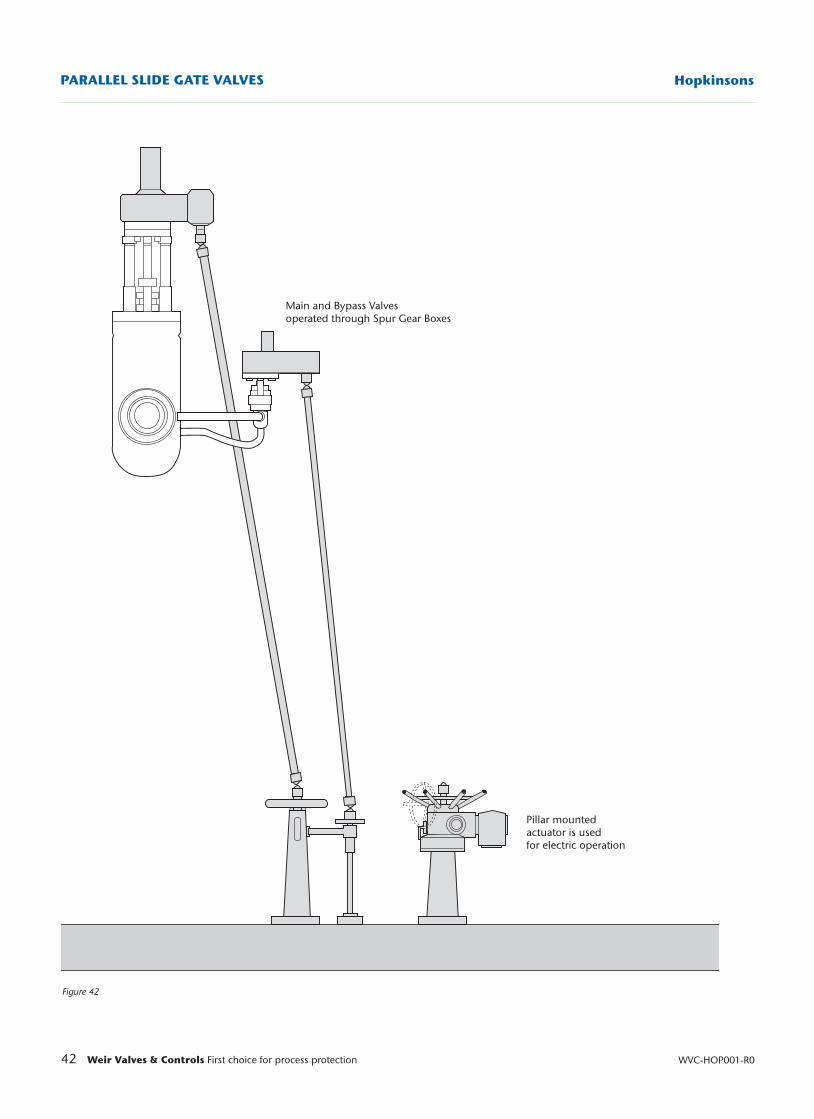
42 Weir Valves & Controls First choice for process protection WVC-HOP001-R0
HopkinsonsPARALLEL SLIDE GATE VALVES
Figure 42
Main and Bypass Valvesoperated through Spur Gear Boxes
Pillar mountedactuator is usedfor electric operation
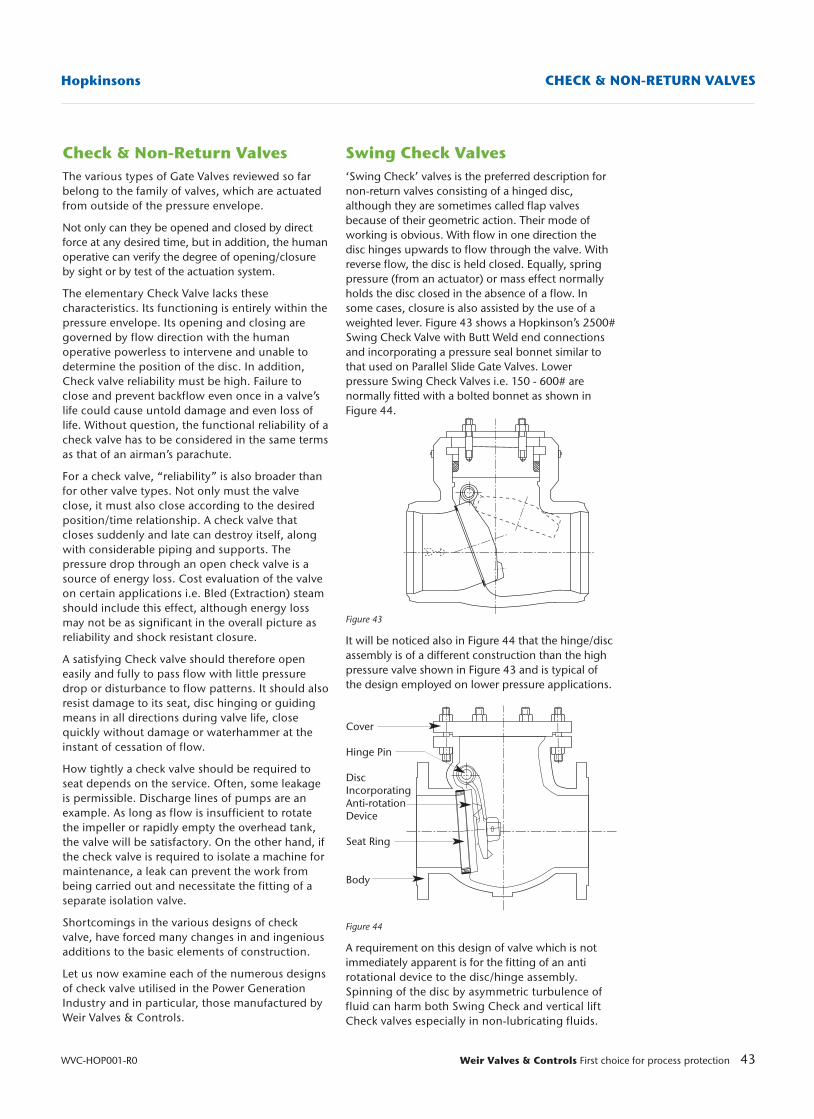
Swing Check Valves‘Swing Check’ valves is the preferred description fornon-return valves consisting of a hinged disc,although they are sometimes called flap valvesbecause of their geometric action. Their mode ofworking is obvious. With flow in one direction thedisc hinges upwards to flow through the valve. Withreverse flow, the disc is held closed. Equally, springpressure (from an actuator) or mass effect normallyholds the disc closed in the absence of a flow. Insome cases, closure is also assisted by the use of aweighted lever. Figure 43 shows a Hopkinson’s 2500#Swing Check Valve with Butt Weld end connectionsand incorporating a pressure seal bonnet similar tothat used on Parallel Slide Gate Valves. Lowerpressure Swing Check Valves i.e. 150 - 600# arenormally fitted with a bolted bonnet as shown inFigure 44.
Figure 43
It will be noticed also in Figure 44 that the hinge/discassembly is of a different construction than the highpressure valve shown in Figure 43 and is typical ofthe design employed on lower pressure applications.
Figure 44
A requirement on this design of valve which is notimmediately apparent is for the fitting of an antirotational device to the disc/hinge assembly.Spinning of the disc by asymmetric turbulence offluid can harm both Swing Check and vertical liftCheck valves especially in non-lubricating fluids.
43Weir Valves & Controls First choice for process protection
Hopkinsons CHECK & NON-RETURN VALVES
WVC-HOP001-R0
Cover
Hinge Pin
DiscIncorporatingAnti-rotationDevice
Seat Ring
Body
Check & Non-Return ValvesThe various types of Gate Valves reviewed so farbelong to the family of valves, which are actuatedfrom outside of the pressure envelope.
Not only can they be opened and closed by directforce at any desired time, but in addition, the humanoperative can verify the degree of opening/closureby sight or by test of the actuation system.
The elementary Check Valve lacks thesecharacteristics. Its functioning is entirely within thepressure envelope. Its opening and closing aregoverned by flow direction with the humanoperative powerless to intervene and unable todetermine the position of the disc. In addition,Check valve reliability must be high. Failure toclose and prevent backflow even once in a valve’slife could cause untold damage and even loss oflife. Without question, the functional reliability of acheck valve has to be considered in the same termsas that of an airman’s parachute.
For a check valve, “reliability” is also broader thanfor other valve types. Not only must the valveclose, it must also close according to the desiredposition/time relationship. A check valve thatcloses suddenly and late can destroy itself, alongwith considerable piping and supports. Thepressure drop through an open check valve is asource of energy loss. Cost evaluation of the valveon certain applications i.e. Bled (Extraction) steamshould include this effect, although energy lossmay not be as significant in the overall picture asreliability and shock resistant closure.
A satisfying Check valve should therefore openeasily and fully to pass flow with little pressuredrop or disturbance to flow patterns. It should alsoresist damage to its seat, disc hinging or guidingmeans in all directions during valve life, closequickly without damage or waterhammer at theinstant of cessation of flow.
How tightly a check valve should be required toseat depends on the service. Often, some leakageis permissible. Discharge lines of pumps are anexample. As long as flow is insufficient to rotatethe impeller or rapidly empty the overhead tank,the valve will be satisfactory. On the other hand, ifthe check valve is required to isolate a machine formaintenance, a leak can prevent the work frombeing carried out and necessitate the fitting of aseparate isolation valve.
Shortcomings in the various designs of checkvalve, have forced many changes in and ingeniousadditions to the basic elements of construction.
Let us now examine each of the numerous designsof check valve utilised in the Power GenerationIndustry and in particular, those manufactured byWeir Valves & Controls.
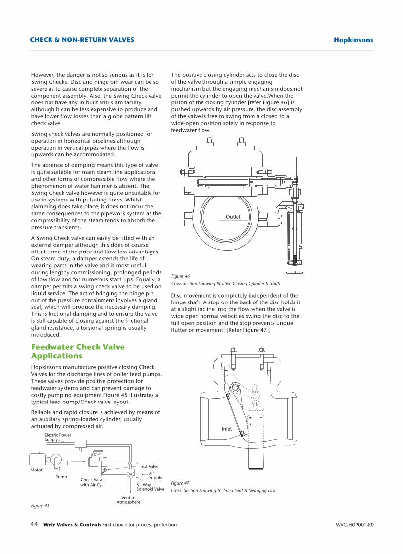
The positive closing cylinder acts to close the discof the valve through a simple engagingmechanism but the engaging mechanism does notpermit the cylinder to open the valve.When thepiston of the closing cylinder [refer Figure 46] ispushed upwards by air pressure, the disc assemblyof the valve is free to swing from a closed to awide-open position solely in response tofeedwater flow.
Disc movement is completely independent of thehinge shaft. A stop on the back of the disc holds itat a slight incline into the flow when the valve iswide open normal velocities swing the disc to thefull open position and the stop prevents undueflutter or movement. [Refer Figure 47.]
44 Weir Valves & Controls First choice for process protection WVC-HOP001-R0
HopkinsonsCHECK & NON-RETURN VALVES
Figure 47
Cross Section Showing Inclined Seat & Swinging Disc
Figure 46
Cross Section Showing Positive Closing Cylinder & Shaft
Figure 45
Electric PowerSupply
Motor
Pump
Vent toAtmosphere
3 - WaySolenoid Valve
Test Valve
AirSupplyCheck Valve
with Air Cyl.
Outlet
Inlet
However, the danger is not so serious as it is forSwing Checks. Disc and hinge pin wear can be sosevere as to cause complete separation of thecomponent assembly. Also, the Swing Check valvedoes not have any in built anti-slam facilityalthough it can be less expensive to produce andhave lower flow losses than a globe pattern liftcheck valve.
Swing check valves are normally positioned foroperation in horizontal pipelines althoughoperation in vertical pipes where the flow isupwards can be accommodated.
The absence of damping means this type of valveis quite suitable for main steam line applicationsand other forms of compressible flow where thephenomenon of water hammer is absent. TheSwing Check valve however is quite unsuitable foruse in systems with pulsating flows. Whilstslamming does take place, it does not incur thesame consequences to the pipework system as thecompressibility of the steam tends to absorb thepressure transients.
A Swing Check valve can easily be fitted with anexternal damper although this does of courseoffset some of the price and flow loss advantages.On steam duty, a damper extends the life ofwearing parts in the valve and is most usefulduring lengthy commissioning, prolonged periodsof low flow and for numerous start-ups. Equally, adamper permits a swing check valve to be used onliquid service. The act of bringing the hinge pinout of the pressure containment involves a glandseal, which will produce the necessary damping.This is frictional damping and to ensure the valveis still capable of closing against the frictionalgland resistance, a torsional spring is usuallyintroduced.
Feedwater Check ValveApplicationsHopkinsons manufacture positive closing CheckValves for the discharge lines of boiler feed pumps.These valves provide positive protection forfeedwater systems and can prevent damage tocostly pumping equipment Figure 45 illustrates atypical feed pump/Check valve layout.
Reliable and rapid closure is achieved by means ofan auxiliary spring-loaded cylinder, usuallyactuated by compressed air.
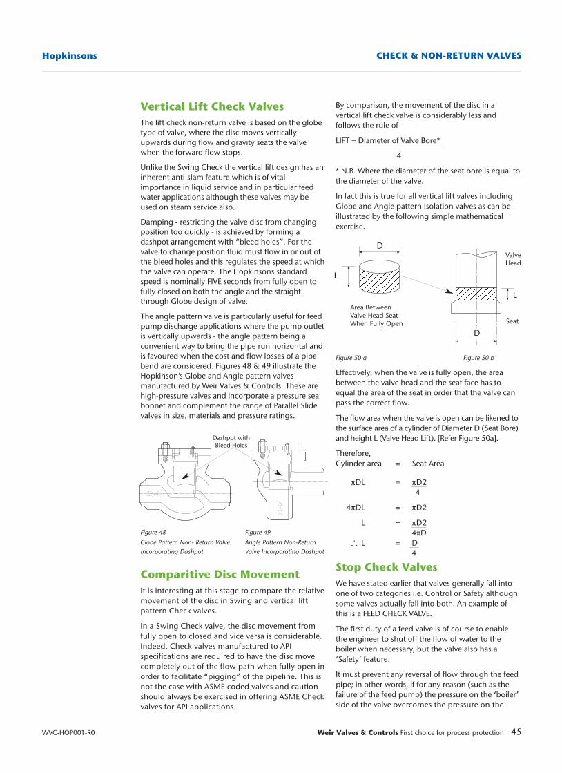
Vertical Lift Check ValvesThe lift check non-return valve is based on the globetype of valve, where the disc moves verticallyupwards during flow and gravity seats the valvewhen the forward flow stops.
Unlike the Swing Check the vertical lift design has aninherent anti-slam feature which is of vitalimportance in liquid service and in particular feedwater applications although these valves may beused on steam service also.
Damping - restricting the valve disc from changingposition too quickly - is achieved by forming adashpot arrangement with “bleed holes”. For thevalve to change position fluid must flow in or out ofthe bleed holes and this regulates the speed at whichthe valve can operate. The Hopkinsons standardspeed is nominally FIVE seconds from fully open tofully closed on both the angle and the straightthrough Globe design of valve.
The angle pattern valve is particularly useful for feedpump discharge applications where the pump outletis vertically upwards - the angle pattern being aconvenient way to bring the pipe run horizontal andis favoured when the cost and flow losses of a pipebend are considered. Figures 48 & 49 illustrate theHopkinson’s Globe and Angle pattern valvesmanufactured by Weir Valves & Controls. These arehigh-pressure valves and incorporate a pressure sealbonnet and complement the range of Parallel Slidevalves in size, materials and pressure ratings.
Figure 48 Figure 49
Globe Pattern Non- Return Valve Angle Pattern Non-ReturnIncorporating Dashpot Valve Incorporating Dashpot
Comparitive Disc MovementIt is interesting at this stage to compare the relativemovement of the disc in Swing and vertical liftpattern Check valves.
In a Swing Check valve, the disc movement fromfully open to closed and vice versa is considerable.Indeed, Check valves manufactured to APIspecifications are required to have the disc movecompletely out of the flow path when fully open inorder to facilitate “pigging” of the pipeline. This isnot the case with ASME coded valves and cautionshould always be exercised in offering ASME Checkvalves for API applications.
45Weir Valves & Controls First choice for process protection
Hopkinsons CHECK & NON-RETURN VALVES
WVC-HOP001-R0
By comparison, the movement of the disc in avertical lift check valve is considerably less andfollows the rule of
LIFT = Diameter of Valve Bore*
4
* N.B. Where the diameter of the seat bore is equal tothe diameter of the valve.
In fact this is true for all vertical lift valves includingGlobe and Angle pattern Isolation valves as can beillustrated by the following simple mathematicalexercise.
Figure 50 a Figure 50 b
Effectively, when the valve is fully open, the areabetween the valve head and the seat face has toequal the area of the seat in order that the valve canpass the correct flow.
The flow area when the valve is open can be likened tothe surface area of a cylinder of Diameter D (Seat Bore)and height L (Valve Head Lift). [Refer Figure 50a].
Therefore, Cylinder area = Seat Area
πDL = πD24
4πDL = πD2
L = πD24πD
L = D4
Stop Check ValvesWe have stated earlier that valves generally fall intoone of two categories i.e. Control or Safety althoughsome valves actually fall into both. An example ofthis is a FEED CHECK VALVE.
The first duty of a feed valve is of course to enablethe engineer to shut off the flow of water to theboiler when necessary, but the valve also has a‘Safety’ feature.
It must prevent any reversal of flow through the feedpipe; in other words, if for any reason (such as thefailure of the feed pump) the pressure on the ‘boiler’side of the valve overcomes the pressure on the
Dashpot withBleed Holes
Area BetweenValve Head SeatWhen Fully Open
ValveHead
Seat
L
L
D
D
.. .
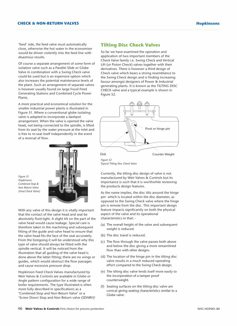
46 Weir Valves & Controls First choice for process protection WVC-HOP001-R0
HopkinsonsCHECK & NON-RETURN VALVES
‘feed’ side, the feed valve must automaticallyclose, otherwise the hot water in the economiserwould be driven violently into the feed line withdisastrous results.
Of course a separate arrangement of some form ofisolation valve such as a Parallel Slide or GlobeValve in combination with a Swing Check valvecould be used but is an expensive option whichalso increases the potential maintenance levels ofthe plant. Such an arrangement of separate valvesis however usually found on large Fossil FiredGenerating Stations and Combined Cycle PowerPlants.
A more practical and economical solution for thesmaller industrial power plants is illustrated inFigure 51. Where a conventional globe isolatingvalve is adapted to incorporate a dashpotarrangement. When the valve is opened the valvehead, not being connected to the spindle, is liftedfrom its seat by the water pressure at the inlet andis free to re-seat itself independently in the eventof a reversal of flow.
Figure 51Hopkinsons Combined Stop & Non Return Valve (Feed Check Valve)
With any valve of this design it is vitally importantthat the contact of the valve head and seat beabsolutely fluid tight. A slight tilt on the part of thevalve head would cause leakage. Special care istherefore taken in the machining and subsequentfitting of the guide and valve head to ensure thatthe valve head fits the face of the seat accurately.From the foregoing it will be understood why thistype of valve should always be fitted with thespindle vertical. It will be noticed from theillustration that all guiding of the valve head isdone above the latter fitting; there are no wings orguides, which would obstruct the flow passagesand cause excessive pressure drop.
Hopkinson Feed Check Valves manufactured byWeir Valves & Controls are available in Globe orAngle pattern configuration for a wide range ofboiler requirements. The type illustrated is oftenmore fully described in specifications as a‘Combined Stop and Non Return Valve’ or a‘Screw Down Stop and Non Return valve (SDNRV)!
Tilting Disc Check ValvesSo far we have examined the operation andapplication of two important members of theCheck Valve family i.e. Swing Check and VerticalLift (or Piston Check) valves together with theirderivatives. There is however a third design ofCheck valve which bears a strong resemblance tothe Swing Check design and is finding increasingfavour amongst designers of Power & Industrialgenerating plants. It is known as the TILTING DISCCHECK valve and a typical example is shown inFigure 52.
Figure 52Typical Tilting Disc Check Valve
Currently, the tilting disc design of valve is notmanufactured by Weir Valves & Controls but itsimportance is such that it is worthwhile reviewingthe products design features.
As the name implies, the disc tilts around the hingepin which is located within the disc diameter, asopposed to the Swing Check valve where the hingepin is remote from the disc. This important designfeature impacts significantly on both the physicalaspect of the valve and its operationalcharacteristics in that: -
(a) The overall height of the valve and subsequent weight is reduced.
(b) The disc travel is reduced.
(c) The flow through the valve passes both above and below the disc giving a more streamlined flow than with other designs.
(d) The location of the hinge pin in the tilting disc valve results in a much reduced operating effort compared to the Swing Check design.
(e) The tilting disc valve lends itself more easily to the incorporation of a tamper proof counterweight.
(f) Seating surfaces on the tilting disc valve are conical giving seating characteristics similar to a Globe valve.
Pivot or hinge pin
Counter WeightDisk
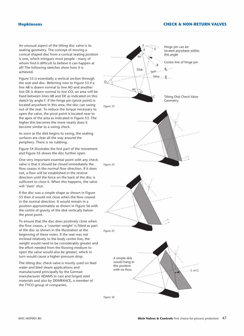
47Weir Valves & Controls First choice for process protection
Hopkinsons CHECK & NON-RETURN VALVES
WVC-HOP001-R0
Figure 53
Figure 54
Figure 55
Figure 56
Hinge pin can be located anywhere within this angle
Centre line of hinge pin
Tilting Disk Check ValveGeometry.
EFA
B
CD
O
90˚
90˚
Seat
Valve
Disk
A simple diskwould hang in this positionwith no flow. C of G
cL
cL
An unusual aspect of the tilting disc valve is itsseating geometry. The concept of moving aconical shaped disc from a conical seating positionis one, which intrigues most people - many ofwhom find it difficult to believe it can happen atall! The following sketches show how it isachieved.
Figure 53 is essentially a vertical section throughthe seat and disc. Referring now to Figure 53 if aline AB is drawn normal to line AO and anotherline DE is drawn normal to line CO, an area will befixed between lines AB and DE as indicated on thissketch by angle F. If the hinge pin (pivot point) islocated anywhere in this area, the disc can swingout of the seat. To reduce the torque necessary toopen the valve, the pivot point is located near tothe apex of the area as indicated in Figure 53. Thehigher this becomes the more nearly does itbecome similar to a swing check.
As soon as the disk begins to swing, the seatingsurfaces are clear all the way around theperiphery. There is no rubbing.
Figure 54 illustrates the first part of the movementand Figure 55 shows the disc further open.
One very important essential point with any checkvalve is that it should be closed immediately theflow ceases in the normal flow direction. If it doesnot, a flow will be established in the reversedirection until the force on the back of the disc issufficient to close it. When this happens, the valvewill ‘slam’ shut.
If the disc was a simple shape as shown in Figure53 then it would not close when the flow ceasedin the normal direction. It would remain in aposition approximately as shown in Figure 56 withthe centre of gravity of the disk vertically belowthe pivot point.
To ensure that the disc does positively close whenthe flow ceases, a ‘counter weight’ is fitted as partof the disc as shown in the illustration at thebeginning of these notes. If the seat was notinclined relatively to the body centre line, theweight would need to be considerably greater andthe effort needed from the flowing medium toopen the valve would also be greater, which inturn would cause a higher pressure drop.
The tilting disc check valve is mostly used on feedwater and bled steam applications andmanufactured principally by the Germanmanufacturer ADAMS in cast and forged steelmaterials and also by DEWRANCE, a member ofthe TYCO group of companies.
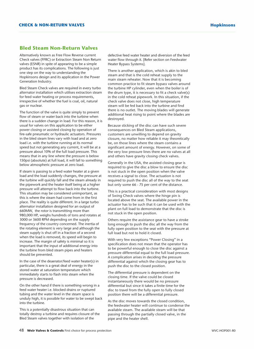
48 Weir Valves & Controls First choice for process protection WVC-HOP001-R0
HopkinsonsCHECK & NON-RETURN VALVES
Bled Steam Non-Return ValvesAlternatively known as Free Flow Reverse currentCheck valves (FFRC) or Extraction Steam Non Returnvalves (ESNR) in spite of appearing to be a simpleproduct has its complications. The following is justone step on the way to understanding theHopkinsons design and its application in the PowerGeneration Industry.
Bled Steam Check valves are required in every turboalternator installation which utilises extraction steamfor feed water heating or process requirements,irrespective of whether the fuel is coal, oil, naturalgas or nuclear.
The function of the valve is quite simply to preventflow of steam or water back into the turbine whenthere is a sudden change in load. For this reason, it isusual for valves on this application to be eitherpower closing or assisted closing by operation offire-safe pneumatic or hydraulic actuators. Pressuresin the bled steam lines vary with load and at zeroload i.e. with the turbine running at its normalspeed but not generating any current, it will be at apressure about 10% of the full load pressure. Thismeans that in any line where the pressure is below150psi (absolute) at full load, it will fall to somethingbelow atmospheric pressure at zero load.
If steam is passing to a feed water heater at a givenload and the load suddenly changes, the pressure atthe turbine will quickly fall and the steam already inthe pipework and the heater itself being at a higherpressure will attempt to flow back into the turbine.This situation may be considered unimportant, asthis is where the steam had come from in the firstplace. The reality is quite different. In a large turboalternator installation designed for an output of660MW, the rotor is transmitting more than980,000 HP, weighs hundreds of tons and rotates at3000 or 3600 RPM depending on the supplyfrequency of the country concerned. The inertia ofthe rotating element is very large and although thesteam supply is shut off in a fraction of a secondwhen the load is removed, its speed will begin toincrease. The margin of safety is minimal so it isimportant that the input of additional energy intothe turbine from bled steam pipes and heatersshould be prevented.
In the case of the deaerator/feed water heater(s) inparticular, there is a great deal of energy in thestored water at saturation temperature whichimmediately starts to flash into steam when thepressure is decreased.
On the other hand if there is something wrong in afeed water heater i.e. blocked drains or rupturedtubing and the water level in the steam space isunduly high, it is possible for water to be swept backinto the turbine.
This is a potentially disastrous situation that cantotally destroy a turbine and requires closure of theBled Steam valves together with isolation of the
defective feed water heater and diversion of the feedwater flow through it. [Refer section on FeedwaterHeater Bypass Systems].
There is another application, which is akin to bledsteam and that is the cold reheat supply to themain steam reheater. Now that it is becomingcommon practice to fit steam bypass valves aroundthe turbine HP cylinder, even when the boiler is ofthe drum type, it is necessary to fit a check valve(s)in the cold reheat pipework. In this situation, if thecheck valve does not close, high temperaturesteam will be fed back into the turbine and findthere is no outlet. The moving blades will generateadditional heat rising to point where the blades aredestroyed.
Because sticking of the disc can have such severeconsequences on Bled Steam applications,customers are unwilling to depend on gravityclosure, no matter how reliable it may theoreticallybe, on those lines where the steam contains asignificant amount of energy. However, on some ofthe very low pressure lines there are no valves at alland others have gravity closing check valves.
Generally in the USA, the assisted closing gear isrequired to give the disc a blow to ensure the discis not stuck in the open position when the valvereceives a signal to close. The actuation is notrequired to push the disc all of the way to the seatbut only some 66 - 75 per cent of the distance.
This is a practical consideration with most designsof Swing Check valves where the hinge pin islocated above the seat. The available power in theactuator has to be such that it can be used with theplant on full load to demonstrate that the disc isnot stuck in the open position.
Others require the assistance gear to have a strokelong enough to push the disc all the way from thefully open position to the seat with the pressure atfull load but not to hold it closed.
With very few exceptions “Power Closing” in aspecification does not mean that the operator hasto be powerful enough to close the disc against apressure differential equal to the full load pressure.A complication arises in deciding the pressuredifferential against which the closing gear has topush the disc to the closed position.
The differential pressure is dependent on theclosing time. If the valve could be closedinstantaneously there would be no pressuredifferential but since it takes a finite time for thedisc to travel from the fully open to fully closedposition there will be a differential pressure.
As the disc moves towards the closed condition,the feedwater heater will continue to condense theavailable steam. The available steam will be thatpassing through the partially closed valve, in thepipe and the heater shell.
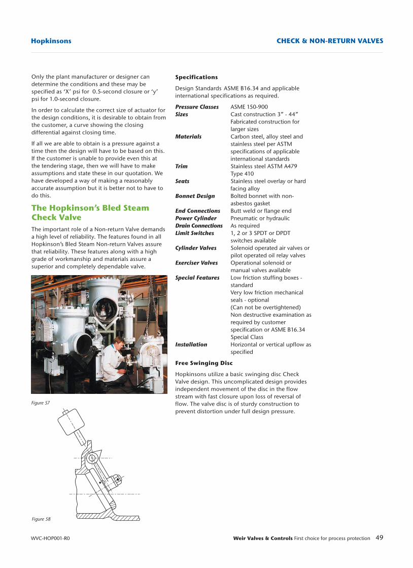
49Weir Valves & Controls First choice for process protection
Hopkinsons CHECK & NON-RETURN VALVES
WVC-HOP001-R0
Figure 57
Figure 58
Specifications
Design Standards ASME B16.34 and applicableinternational specifications as required.
Pressure Classes ASME 150-900Sizes Cast construction 3” - 44”
Fabricated construction for larger sizes
Materials Carbon steel, alloy steel and stainless steel per ASTM specifications of applicableinternational standards
Trim Stainless steel ASTM A479 Type 410
Seats Stainless steel overlay or hardfacing alloy
Bonnet Design Bolted bonnet with non-asbestos gasket
End Connections Butt weld or flange endPower Cylinder Pneumatic or hydraulicDrain Connections As requiredLimit Switches 1, 2 or 3 SPDT or DPDT
switches availableCylinder Valves Solenoid operated air valves or
pilot operated oil relay valvesExerciser Valves Operational solenoid or
manual valves availableSpecial Features Low friction stuffing boxes -
standardVery low friction mechanical seals - optional (Can not be overtightened)Non destructive examination asrequired by customerspecification or ASME B16.34 Special Class
Installation Horizontal or vertical upflow asspecified
Free Swinging Disc
Hopkinsons utilize a basic swinging disc CheckValve design. This uncomplicated design providesindependent movement of the disc in the flowstream with fast closure upon loss of reversal offlow. The valve disc is of sturdy construction toprevent distortion under full design pressure.
Only the plant manufacturer or designer candetermine the conditions and these may bespecified as ‘X’ psi for 0.5-second closure or ‘y’psi for 1.0-second closure.
In order to calculate the correct size of actuator forthe design conditions, it is desirable to obtain fromthe customer, a curve showing the closingdifferential against closing time.
If all we are able to obtain is a pressure against atime then the design will have to be based on this.If the customer is unable to provide even this atthe tendering stage, then we will have to makeassumptions and state these in our quotation. Wehave developed a way of making a reasonablyaccurate assumption but it is better not to have todo this.
The Hopkinson’s Bled SteamCheck ValveThe important role of a Non-return Valve demandsa high level of reliability. The features found in allHopkinson’s Bled Steam Non-return Valves assurethat reliability. These features along with a highgrade of workmanship and materials assure asuperior and completely dependable valve.
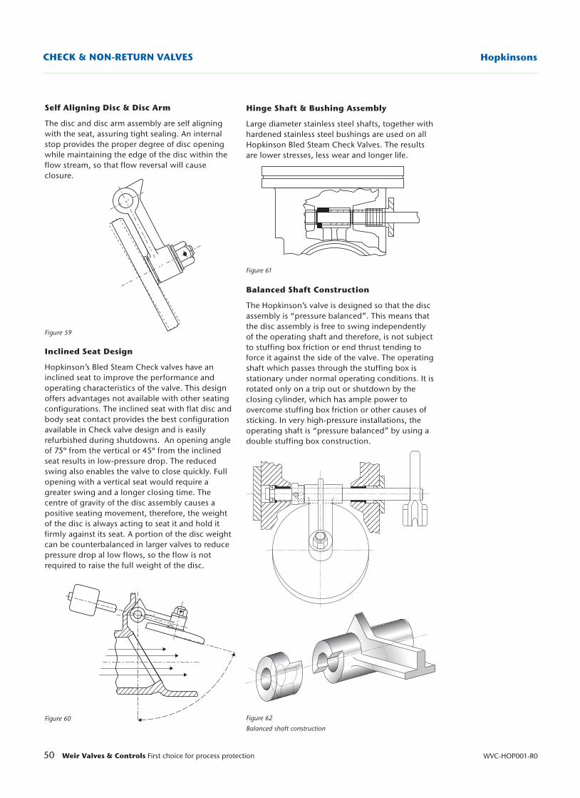
Hinge Shaft & Bushing Assembly
Large diameter stainless steel shafts, together withhardened stainless steel bushings are used on allHopkinson Bled Steam Check Valves. The resultsare lower stresses, less wear and longer life.
Figure 61
Balanced Shaft Construction
The Hopkinson’s valve is designed so that the discassembly is “pressure balanced”. This means thatthe disc assembly is free to swing independentlyof the operating shaft and therefore, is not subjectto stuffing box friction or end thrust tending toforce it against the side of the valve. The operatingshaft which passes through the stuffing box isstationary under normal operating conditions. It isrotated only on a trip out or shutdown by theclosing cylinder, which has ample power toovercome stuffing box friction or other causes ofsticking. In very high-pressure installations, theoperating shaft is “pressure balanced” by using adouble stuffing box construction.
Figure 62
Balanced shaft construction
Self Aligning Disc & Disc Arm
The disc and disc arm assembly are self aligningwith the seat, assuring tight sealing. An internalstop provides the proper degree of disc openingwhile maintaining the edge of the disc within theflow stream, so that flow reversal will causeclosure.
Figure 59
Inclined Seat Design
Hopkinson’s Bled Steam Check valves have aninclined seat to improve the performance andoperating characteristics of the valve. This designoffers advantages not available with other seatingconfigurations. The inclined seat with flat disc andbody seat contact provides the best configurationavailable in Check valve design and is easilyrefurbished during shutdowns. An opening angleof 75º from the vertical or 45º from the inclinedseat results in low-pressure drop. The reducedswing also enables the valve to close quickly. Fullopening with a vertical seat would require agreater swing and a longer closing time. Thecentre of gravity of the disc assembly causes apositive seating movement, therefore, the weightof the disc is always acting to seat it and hold itfirmly against its seat. A portion of the disc weightcan be counterbalanced in larger valves to reducepressure drop al low flows, so the flow is notrequired to raise the full weight of the disc.
Figure 60
50 Weir Valves & Controls First choice for process protection WVC-HOP001-R0
HopkinsonsCHECK & NON-RETURN VALVES
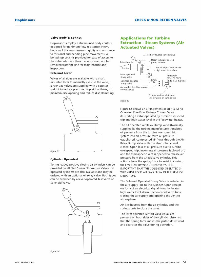
Valve Body & Bonnet
Hopkinsons employ a streamlined body contourdesigned for minimum flow resistance. Heavybody wall thickness assures rigidity and resistanceto torsional and bending pipe movements. Abolted top cover is provided for ease of access tothe valve internals, thus the valve need not beremoved from the line for maintenance andinspection.
External Lever
Valves of all sizes are available with a shaftmounted lever to manually exercise the valve,larger size valves are supplied with a counterweight to reduce pressure drop at low flows, tomaintain disc opening and reduce disc slamming.
Figure 63
Cylinder Operated
Spring loaded positive closing air cylinders can beprovided on all Bled Steam Non-return Valves. Oiloperated cylinders are also available and may beordered with an optional oil relay valve. Both typescan be exercised by a lever operated Test Valve orSolenoid Valve.
Figure 64
51Weir Valves & Controls First choice for process protection
Hopkinsons CHECK & NON-RETURN VALVES
WVC-HOP001-R0
Applications for TurbineExtraction - Steam Systems (AirActuated Valves)
Figure 65
Figure 65 shows an arrangement of an A & M AirOperated Free Flow Reverse Current Valveillustrating a valve operated by turbine overspeedtrip and high water level in the feedwater heater.
The oil operated Air Relay Dump valve (Normallysupplied by the turbine manufacture) translatesoil pressure from the turbine overspeed tripsystem into air pressure. With oil pressureestablished, compressed air flows through the AirRelay Dump Valve with the atmospheric ventclosed. Upon loss of oil pressure due to turbineoverspeed trip, incoming air pressure is closed off,and the atmospheric vent is opened to release airpressure from the Check Valve cylinder. Thisaction allows the spring force to assist in closingthe Free Flow Reverse Current Valve. IT ISIMPORTANT THAT THE SOLENOID OPERATED 3-WAY VALVE USED ALLOWS FLOW IN THE REVERSEDIRECTION.
The Solenoid Operated 3-way Valve is installed inthe air supply line to the cylinder. Upon receipt(or loss) of an electrical signal from the heaterhigh water level alarm, the Solenoid Valve trips,closing the air supply and opening the vent toatmosphere.
Air is exhausted from the air cylinder, and thespring starts to close the valve.
The lever operated Air test Valve equalizespressure on both sides of the cylinder piston sothat the spring force moves the piston downwardand exercises the valve during operation.
Free flow reverse current valve
Steam to heater or feed pump turbine
Electric signal from heaterhigh water level alarm
Extraction line
Oil operated air pilot valve(Air exhaust) on turbine trip
Lever operated3-way valve
Solenoid operated3-way valve
Air to other free flow reversecurrent valves
Air supply(60–125 PSIG)(4.25–8.75 Kg/cm2)
Turbine
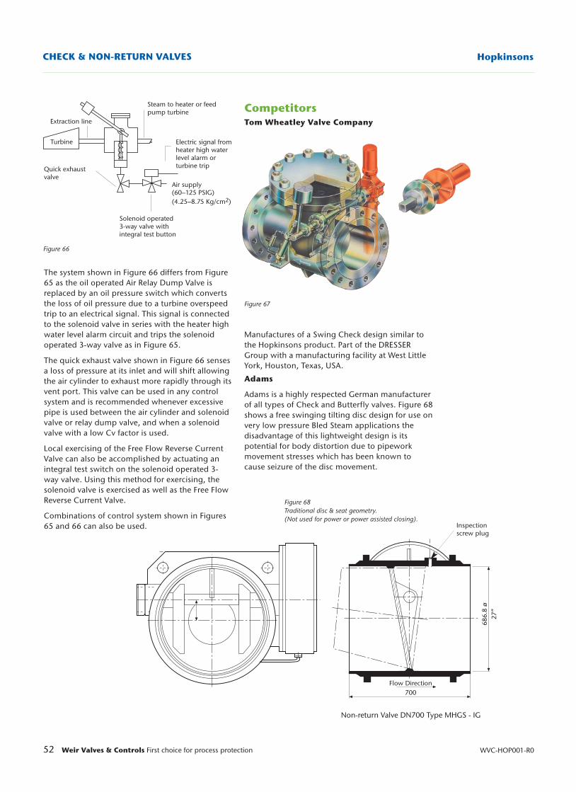
52 Weir Valves & Controls First choice for process protection WVC-HOP001-R0
HopkinsonsCHECK & NON-RETURN VALVES
Steam to heater or feedpump turbine
Electric signal fromheater high waterlevel alarm or turbine trip
Extraction line
Quick exhaustvalve
Solenoid operated 3-way valve with integral test button
Turbine
Air supply(60–125 PSIG)(4.25–8.75 Kg/cm2)
Figure 66
Figure 68 Traditional disc & seat geometry. (Not used for power or power assisted closing).
Inspectionscrew plug
686.
8 ø
27”
Flow Direction700
Non-return Valve DN700 Type MHGS - IG
The system shown in Figure 66 differs from Figure65 as the oil operated Air Relay Dump Valve isreplaced by an oil pressure switch which convertsthe loss of oil pressure due to a turbine overspeedtrip to an electrical signal. This signal is connectedto the solenoid valve in series with the heater highwater level alarm circuit and trips the solenoidoperated 3-way valve as in Figure 65.
The quick exhaust valve shown in Figure 66 sensesa loss of pressure at its inlet and will shift allowingthe air cylinder to exhaust more rapidly through itsvent port. This valve can be used in any controlsystem and is recommended whenever excessivepipe is used between the air cylinder and solenoidvalve or relay dump valve, and when a solenoidvalve with a low Cv factor is used.
Local exercising of the Free Flow Reverse CurrentValve can also be accomplished by actuating anintegral test switch on the solenoid operated 3-way valve. Using this method for exercising, thesolenoid valve is exercised as well as the Free FlowReverse Current Valve.
Combinations of control system shown in Figures65 and 66 can also be used.
CompetitorsTom Wheatley Valve Company
Figure 67
Manufactures of a Swing Check design similar tothe Hopkinsons product. Part of the DRESSERGroup with a manufacturing facility at West LittleYork, Houston, Texas, USA.
Adams
Adams is a highly respected German manufacturerof all types of Check and Butterfly valves. Figure 68shows a free swinging tilting disc design for use onvery low pressure Bled Steam applications thedisadvantage of this lightweight design is itspotential for body distortion due to pipeworkmovement stresses which has been known tocause seizure of the disc movement.
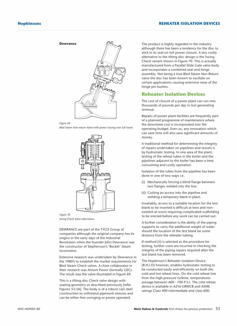
53Weir Valves & Controls First choice for process protection
Hopkinsons REHEATER ISOLATION DEVICES
WVC-HOP001-R0
Dewrance
Figure 69
Bled Steam Non-return Valve with power closing over full travel.
Figure 70
Swing Check Valve alternative.
DEWRANCE are part of the TYCO Group ofcompanies although the original company has itsorigins in the early days of the IndustrialRevolution when the founder John Dewrance wasthe constructor of Stephenson’s ‘Rocket’ Steamlocomotive.
Extensive research was undertaken by Dewrance inthe 1980’s to establish the market requirements forBled Steam Check valves. A close collaborator intheir research was Alstom Power (formally GEC).The result was the valve illustrated in Figure 69.
This is a tilting disc Check valve design withseating geometry as described previously [referFigures 53-56]. The body is of a robust cast steelconstruction to withstand pipework stresses andcan be either free swinging or power operated.
The product is highly regarded in the industryalthough there has been a tendency for the disc tostick in its seat on full power closure. A less costlyalternative to the tilting disc design is the SwingCheck variant shown in Figure 70. This is actuallymanufactured from a Parallel Slide Gate valve bodyand incorporates a combined seat and hingeassembly. Not being a true Bled Steam Non Returnvalve the disc has been known to oscillate oncertain applications causing extensive wear of thehinge pin bushes.
Reheater Isolation DevicesThe cost of closure of a power plant can run intothousands of pounds per day in lost generatingrevenue.
Repairs of power plant facilities are frequently partof a planned programme of maintenance wherethe downtime cost is incorporated into theoperating budget. Even so, any innovation whichcan save time will also save significant amounts ofmoney.
A traditional method for determining the integrityof repairs undertaken on pipelines and vessels isby hydrostatic testing. In one area of the plant,testing of the reheat tubes in the boiler and thepipelines adjacent to the boiler has been a timeconsuming and costly operation.
Isolation of the tubes from the pipeline has beendone in one of two ways i.e.
(i) Mechanically forcing a blind flange between two flanges welded into the line.
(ii) Cutting an access into the pipeline and welding a temporary blank in place.
Invariably, access to a suitable location for the testblank to be inserted is difficult at best and non-existent at worst requiring complicated scaffoldingto be erected before any work can be carried out.
A further consideration is the ability of the pipingsupports to carry the additional weight of watershould the location of the test blank be somedistance from the reheater tubing.
If method (ii) is selected as the procedure fortesting, further costs are incurred in checking theintegrity of the piping repairs required after thetest blank has been removed.
The Hopkinson’s Reheater Isolation Device(R.H.I.D) however, enables hydrostatic testing tobe conducted easily and efficiently on both thecold and hot reheat lines. On the cold reheat linefrom the high-pressure turbine, temperaturesaverage between 600 - 700 P.S.I. The cold reheatdevice is available in A216-GRWCB and ASMEratings Class 400 intermediate and class 600.
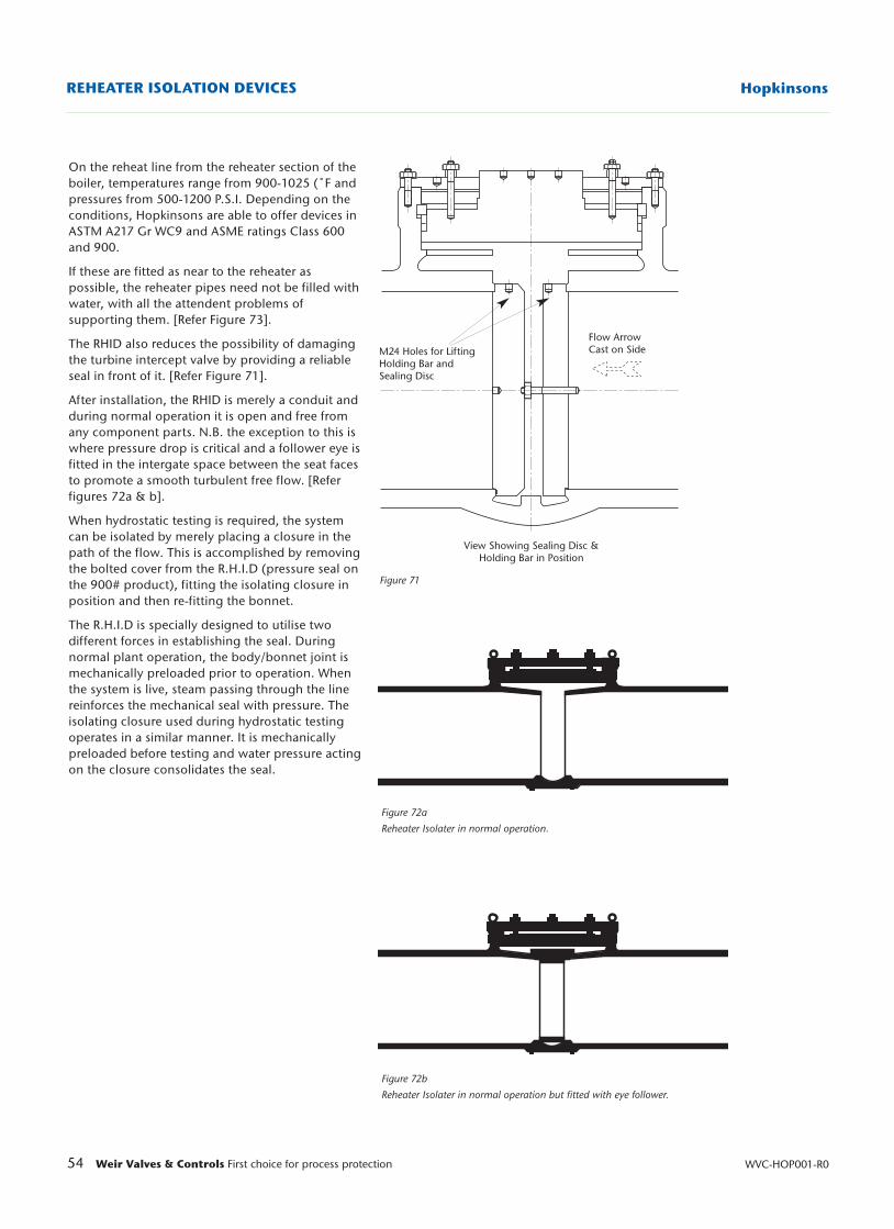
54 Weir Valves & Controls First choice for process protection WVC-HOP001-R0
HopkinsonsREHEATER ISOLATION DEVICES
Figure 71
Figure 72a
Reheater Isolater in normal operation.
Figure 72b
Reheater Isolater in normal operation but fitted with eye follower.
On the reheat line from the reheater section of theboiler, temperatures range from 900-1025 (˚F andpressures from 500-1200 P.S.I. Depending on theconditions, Hopkinsons are able to offer devices inASTM A217 Gr WC9 and ASME ratings Class 600and 900.
If these are fitted as near to the reheater aspossible, the reheater pipes need not be filled withwater, with all the attendent problems ofsupporting them. [Refer Figure 73].
The RHID also reduces the possibility of damagingthe turbine intercept valve by providing a reliableseal in front of it. [Refer Figure 71].
After installation, the RHID is merely a conduit andduring normal operation it is open and free fromany component parts. N.B. the exception to this iswhere pressure drop is critical and a follower eye isfitted in the intergate space between the seat facesto promote a smooth turbulent free flow. [Referfigures 72a & b].
When hydrostatic testing is required, the systemcan be isolated by merely placing a closure in thepath of the flow. This is accomplished by removingthe bolted cover from the R.H.I.D (pressure seal onthe 900# product), fitting the isolating closure inposition and then re-fitting the bonnet.
The R.H.I.D is specially designed to utilise twodifferent forces in establishing the seal. Duringnormal plant operation, the body/bonnet joint ismechanically preloaded prior to operation. Whenthe system is live, steam passing through the linereinforces the mechanical seal with pressure. Theisolating closure used during hydrostatic testingoperates in a similar manner. It is mechanicallypreloaded before testing and water pressure actingon the closure consolidates the seal.
M24 Holes for LiftingHolding Bar andSealing Disc
Flow ArrowCast on Side
View Showing Sealing Disc &Holding Bar in Position
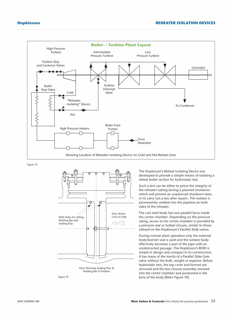
55Weir Valves & Controls First choice for process protection
Hopkinsons REHEATER ISOLATION DEVICES
WVC-HOP001-R0
Boiler – Turbine Plant LayoutHigh Pressure
Turbine
Turbine Stopand Governor Valves
IntermediatePressure Turbine
LowPressure Turbine
Generator
To Condenser
FromDeaerator
Boiler FeedPumpsHigh Pressure Heaters
Hot
“ReheaterIsolating” Device
Cold
BoilerStop Valve
TurbineIntercept
Valve
Showing Location of Reheater Isolating Device on Cold and Hot Reheat Lines
M24 Holes for LiftingHolding Bar andSealing Disc
Flow ArrowCast on Side
View Showing Sealing Disc &Holding Bar in Position
The Hopkinson’s Reheat Isolating Device wasdeveloped to provide a simple means of isolating areheat boiler section for hydrostatic test.
Such a test can be either to prove the integrity ofthe reheater tubing during a planned shutdownwhich will prevent an unplanned shutdown later,or to carry out a test after repairs. The isolator ispermanently welded into the pipeline on bothsides of the reheater.
The cast steel body has two parallel faces insidethe centre chamber. Depending on the pressurerating, access to the centre chamber is provided bya pressure seal or bolted closure, similar to thoseutilised on the Hopkinson’s Parallel Slide valves.
During normal plant operation only the externalbody/bonnet seal is used and the isolator bodyeffectively becomes a part of the pipe with anunobstructed passage. The Hopkinson’s RHID issimple in design and compact in its construction.It has many of the merits of a Parallel Slide Gatevalve without the bulk, weight or expense. Beforehydrostatic test, the top cover and bonnet areremoved and the test closure assembly loweredinto the centre chamber and positioned in thebore of the body [Refer Figure 74].
Figure 73
Figure 74
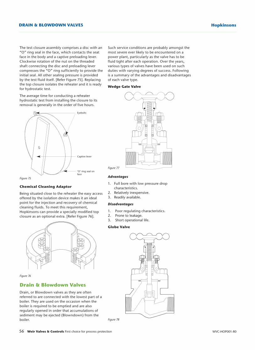
56 Weir Valves & Controls First choice for process protection WVC-HOP001-R0
HopkinsonsDRAIN & BLOWDOWN VALVES
The test closure assembly comprises a disc with an“O” ring seal in the face, which contacts the seatface in the body and a captive preloading lever.Clockwise rotation of the nut on the threadedshaft connecting the disc and preloading levercompresses the “O” ring sufficiently to provide theinitial seal. All other sealing pressure is providedby the test fluid itself. [Refer Figure 75]. Replacingthe top closure isolates the reheater and it is readyfor hydrostatic test.
The average time for conducting a reheaterhydrostatic test from installing the closure to itsremoval is generally in the order of five hours.
Figure 75
Chemical Cleaning Adaptor
Being situated close to the reheater the easy accessoffered by the isolation device makes it an idealpoint for the injection and recovery of chemicalcleaning fluids. To meet this requirement,Hopkinsons can provide a specially modified topclosure as an optional extra. [Refer Figure 76].
Figure 76
Drain & Blowdown ValvesDrain, or Blowdown valves as they are oftenreferred to are connected with the lowest part of aboiler. They are used on the occasion when theboiler is required to be emptied and are alsoregularly opened in order that accumulations ofsediment may be ejected (Blowndown) from theboiler.
Eyebolts
Captive lever
‘O’ ring seal onface
Such service conditions are probably amongst themost severe ever likely to be encountered on apower plant, particularly as the valve has to befluid tight after each operation. Over the years,various types of valves have been used on suchduties with varying degrees of success. Followingis a summary of the advantages and disadvantagesof each valve type.
Wedge Gate Valve
Figure 77
Advantages
1. Full bore with low pressure drop characteristics.
2. Relatively inexpensive.3. Readily available.
Disadvantages
1. Poor regulating characteristics.2. Prone to leakage.3. Short operational life.
Globe Valve
Figure 78
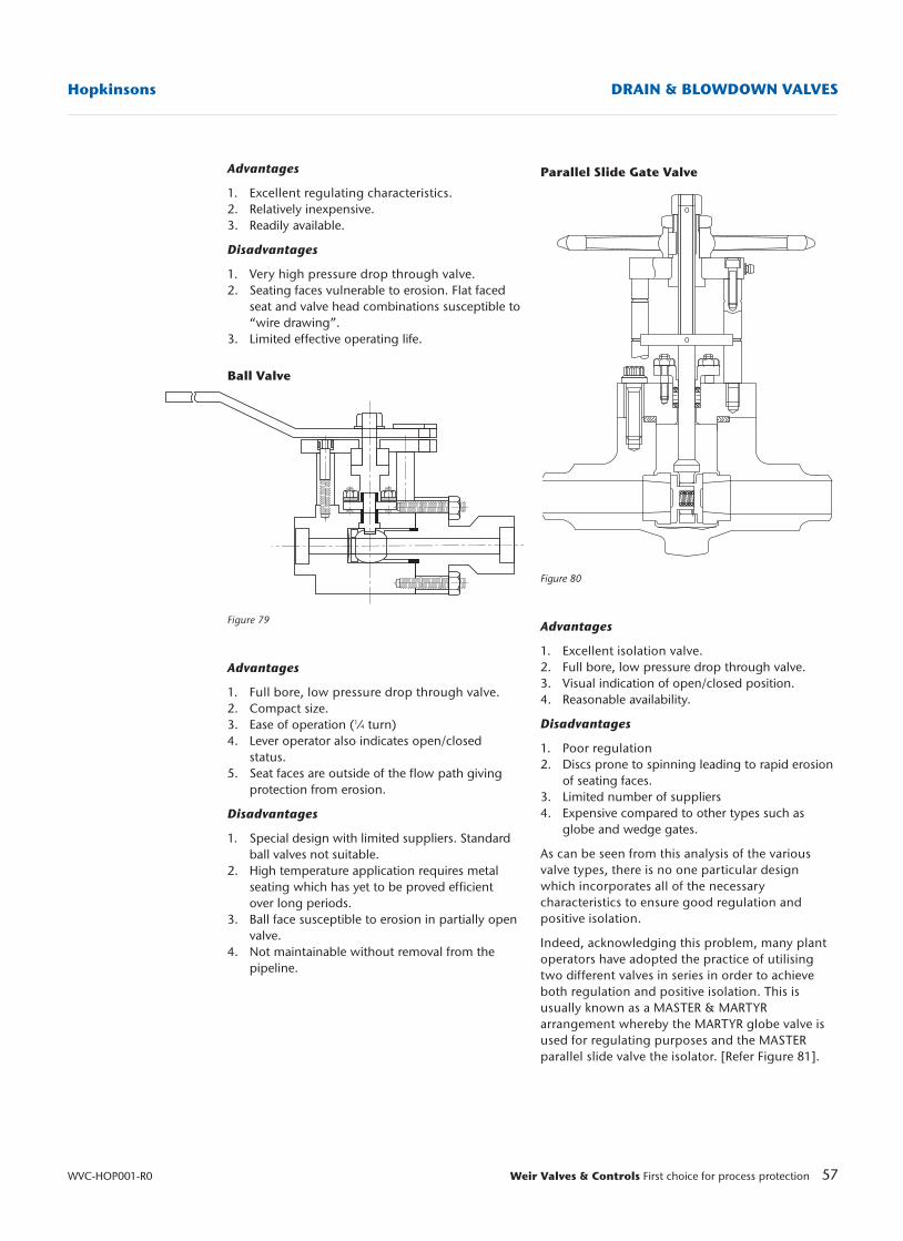
57Weir Valves & Controls First choice for process protection
Hopkinsons DRAIN & BLOWDOWN VALVES
WVC-HOP001-R0
Parallel Slide Gate Valve
Figure 80
Advantages
1. Excellent isolation valve.2. Full bore, low pressure drop through valve.3. Visual indication of open/closed position.4. Reasonable availability.
Disadvantages
1. Poor regulation2. Discs prone to spinning leading to rapid erosion
of seating faces.3. Limited number of suppliers4. Expensive compared to other types such as
globe and wedge gates.
As can be seen from this analysis of the variousvalve types, there is no one particular designwhich incorporates all of the necessarycharacteristics to ensure good regulation andpositive isolation.
Indeed, acknowledging this problem, many plantoperators have adopted the practice of utilisingtwo different valves in series in order to achieveboth regulation and positive isolation. This isusually known as a MASTER & MARTYRarrangement whereby the MARTYR globe valve isused for regulating purposes and the MASTERparallel slide valve the isolator. [Refer Figure 81].
Advantages
1. Excellent regulating characteristics.2. Relatively inexpensive.3. Readily available.
Disadvantages
1. Very high pressure drop through valve.2. Seating faces vulnerable to erosion. Flat faced
seat and valve head combinations susceptible to“wire drawing”.
3. Limited effective operating life.
Ball Valve
Figure 79
Advantages
1. Full bore, low pressure drop through valve.2. Compact size.3. Ease of operation (1⁄4 turn)4. Lever operator also indicates open/closed
status.5. Seat faces are outside of the flow path giving
protection from erosion.
Disadvantages
1. Special design with limited suppliers. Standard ball valves not suitable.
2. High temperature application requires metal seating which has yet to be proved efficient over long periods.
3. Ball face susceptible to erosion in partially open valve.
4. Not maintainable without removal from the pipeline.
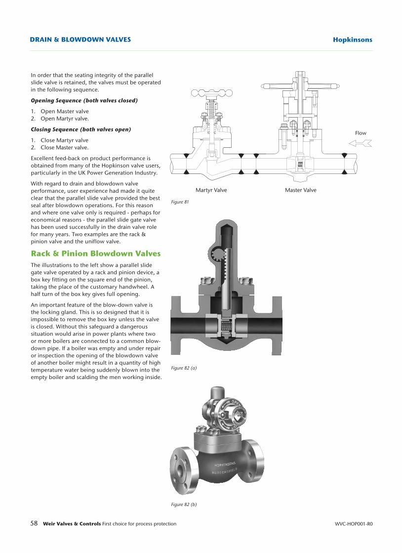
58 Weir Valves & Controls First choice for process protection WVC-HOP001-R0
HopkinsonsDRAIN & BLOWDOWN VALVES
Figure 81
Figure 82 (a)
Figure 82 (b)
In order that the seating integrity of the parallelslide valve is retained, the valves must be operatedin the following sequence.
Opening Sequence (both valves closed)
1. Open Master valve2. Open Martyr valve.
Closing Sequence (both valves open)
1. Close Martyr valve2. Close Master valve.
Excellent feed-back on product performance isobtained from many of the Hopkinson valve users,particularly in the UK Power Generation Industry.
With regard to drain and blowdown valveperformance, user experience had made it quiteclear that the parallel slide valve provided the bestseal after blowdown operations. For this reasonand where one valve only is required - perhaps foreconomical reasons - the parallel slide gate valvehas been used successfully in the drain valve rolefor many years. Two examples are the rack &pinion valve and the uniflow valve.
Rack & Pinion Blowdown ValvesThe illustrations to the left show a parallel slidegate valve operated by a rack and pinion device, abox key fitting on the square end of the pinion,taking the place of the customary handwheel. Ahalf turn of the box key gives full opening.
An important feature of the blow-down valve isthe locking gland. This is so designed that it isimpossible to remove the box key unless the valveis closed. Without this safeguard a dangeroussituation would arise in power plants where twoor more boilers are connected to a common blow-down pipe. If a boiler was empty and under repairor inspection the opening of the blowdown valveof another boiler might result in a quantity of hightemperature water being suddenly blown into theempty boiler and scalding the men working inside.
Martyr Valve Master Valve
Flow
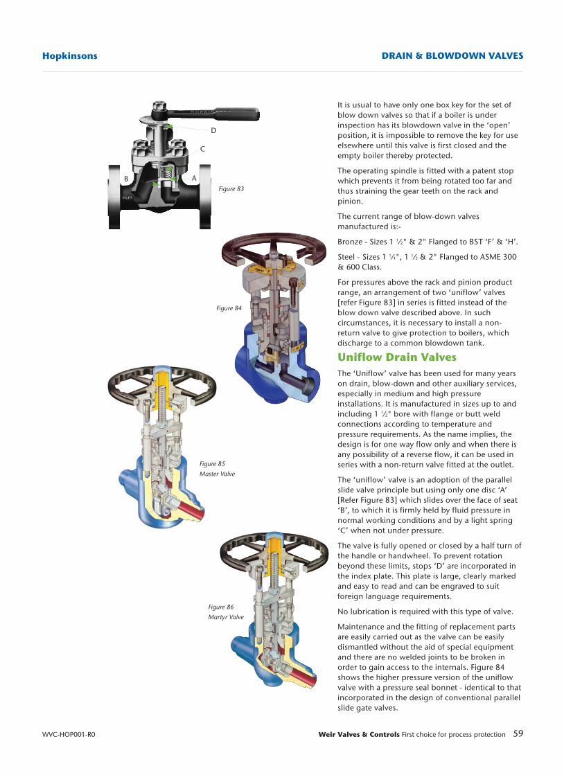
59Weir Valves & Controls First choice for process protection
Hopkinsons DRAIN & BLOWDOWN VALVES
WVC-HOP001-R0
Figure 83
Figure 84
Figure 86
Martyr Valve
Figure 85
Master Valve
It is usual to have only one box key for the set ofblow down valves so that if a boiler is underinspection has its blowdown valve in the ‘open’position, it is impossible to remove the key for useelsewhere until this valve is first closed and theempty boiler thereby protected.
The operating spindle is fitted with a patent stopwhich prevents it from being rotated too far andthus straining the gear teeth on the rack andpinion.
The current range of blow-down valvesmanufactured is:-
Bronze - Sizes 1 1⁄2" & 2" Flanged to BST ‘F’ & ‘H’.
Steel - Sizes 1 1⁄4", 1 1⁄2 & 2" Flanged to ASME 300& 600 Class.
For pressures above the rack and pinion productrange, an arrangement of two ‘uniflow’ valves[refer Figure 83] in series is fitted instead of theblow down valve described above. In suchcircumstances, it is necessary to install a non-return valve to give protection to boilers, whichdischarge to a common blowdown tank.
Uniflow Drain ValvesThe ‘Uniflow’ valve has been used for many yearson drain, blow-down and other auxiliary services,especially in medium and high pressureinstallations. It is manufactured in sizes up to andincluding 1 1⁄2" bore with flange or butt weldconnections according to temperature andpressure requirements. As the name implies, thedesign is for one way flow only and when there isany possibility of a reverse flow, it can be used inseries with a non-return valve fitted at the outlet.
The ‘uniflow’ valve is an adoption of the parallelslide valve principle but using only one disc ‘A’[Refer Figure 83] which slides over the face of seat‘B’, to which it is firmly held by fluid pressure innormal working conditions and by a light spring‘C’ when not under pressure.
The valve is fully opened or closed by a half turn ofthe handle or handwheel. To prevent rotationbeyond these limits, stops ‘D’ are incorporated inthe index plate. This plate is large, clearly markedand easy to read and can be engraved to suitforeign language requirements.
No lubrication is required with this type of valve.
Maintenance and the fitting of replacement partsare easily carried out as the valve can be easilydismantled without the aid of special equipmentand there are no welded joints to be broken inorder to gain access to the internals. Figure 84shows the higher pressure version of the uniflowvalve with a pressure seal bonnet - identical to thatincorporated in the design of conventional parallelslide gate valves.
D
C
AB
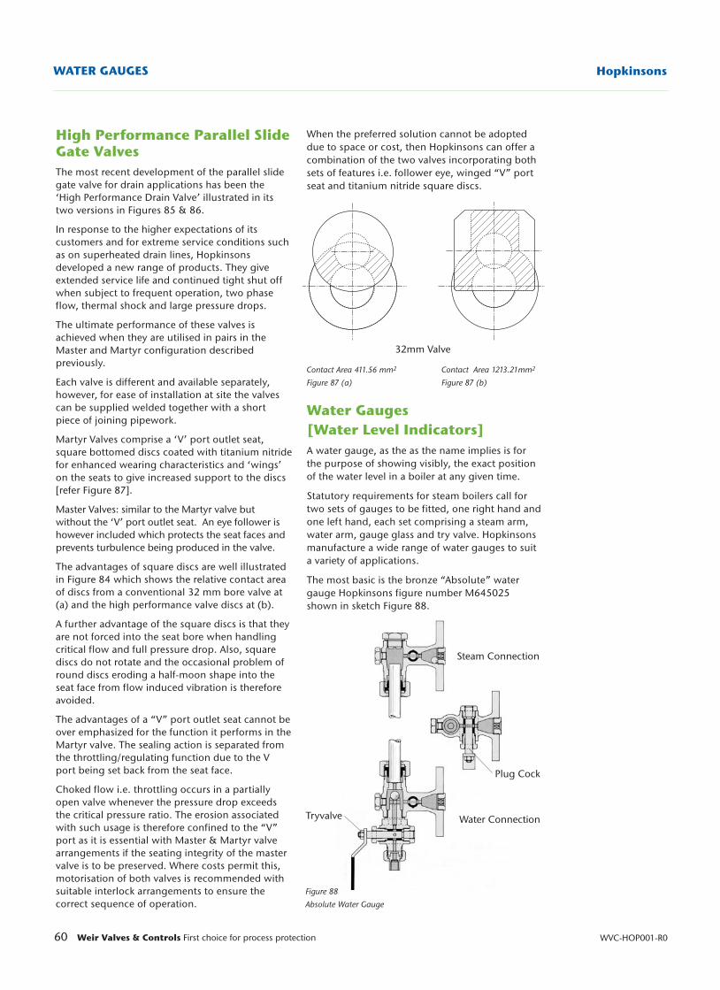
32mm Valve
60 Weir Valves & Controls First choice for process protection WVC-HOP001-R0
HopkinsonsWATER GAUGES
When the preferred solution cannot be adopteddue to space or cost, then Hopkinsons can offer acombination of the two valves incorporating bothsets of features i.e. follower eye, winged “V” portseat and titanium nitride square discs.
Water Gauges [Water Level Indicators]A water gauge, as the as the name implies is forthe purpose of showing visibly, the exact positionof the water level in a boiler at any given time.
Statutory requirements for steam boilers call fortwo sets of gauges to be fitted, one right hand andone left hand, each set comprising a steam arm,water arm, gauge glass and try valve. Hopkinsonsmanufacture a wide range of water gauges to suita variety of applications.
The most basic is the bronze “Absolute” watergauge Hopkinsons figure number M645025shown in sketch Figure 88.
Contact Area 411.56 mm2
Figure 87 (a)
Contact Area 1213.21mm2
Figure 87 (b)
Figure 88
Absolute Water Gauge
High Performance Parallel SlideGate Valves The most recent development of the parallel slidegate valve for drain applications has been the‘High Performance Drain Valve’ illustrated in itstwo versions in Figures 85 & 86.
In response to the higher expectations of itscustomers and for extreme service conditions suchas on superheated drain lines, Hopkinsonsdeveloped a new range of products. They giveextended service life and continued tight shut offwhen subject to frequent operation, two phaseflow, thermal shock and large pressure drops.
The ultimate performance of these valves isachieved when they are utilised in pairs in theMaster and Martyr configuration describedpreviously.
Each valve is different and available separately,however, for ease of installation at site the valvescan be supplied welded together with a shortpiece of joining pipework.
Martyr Valves comprise a ‘V’ port outlet seat,square bottomed discs coated with titanium nitridefor enhanced wearing characteristics and ‘wings’on the seats to give increased support to the discs[refer Figure 87].
Master Valves: similar to the Martyr valve butwithout the ‘V’ port outlet seat. An eye follower ishowever included which protects the seat faces andprevents turbulence being produced in the valve.
The advantages of square discs are well illustratedin Figure 84 which shows the relative contact areaof discs from a conventional 32 mm bore valve at(a) and the high performance valve discs at (b).
A further advantage of the square discs is that theyare not forced into the seat bore when handlingcritical flow and full pressure drop. Also, squarediscs do not rotate and the occasional problem ofround discs eroding a half-moon shape into theseat face from flow induced vibration is thereforeavoided.
The advantages of a “V” port outlet seat cannot beover emphasized for the function it performs in theMartyr valve. The sealing action is separated fromthe throttling/regulating function due to the Vport being set back from the seat face.
Choked flow i.e. throttling occurs in a partiallyopen valve whenever the pressure drop exceedsthe critical pressure ratio. The erosion associatedwith such usage is therefore confined to the “V”port as it is essential with Master & Martyr valvearrangements if the seating integrity of the mastervalve is to be preserved. Where costs permit this,motorisation of both valves is recommended withsuitable interlock arrangements to ensure thecorrect sequence of operation.
Steam Connection
Water ConnectionTryvalve
Plug Cock
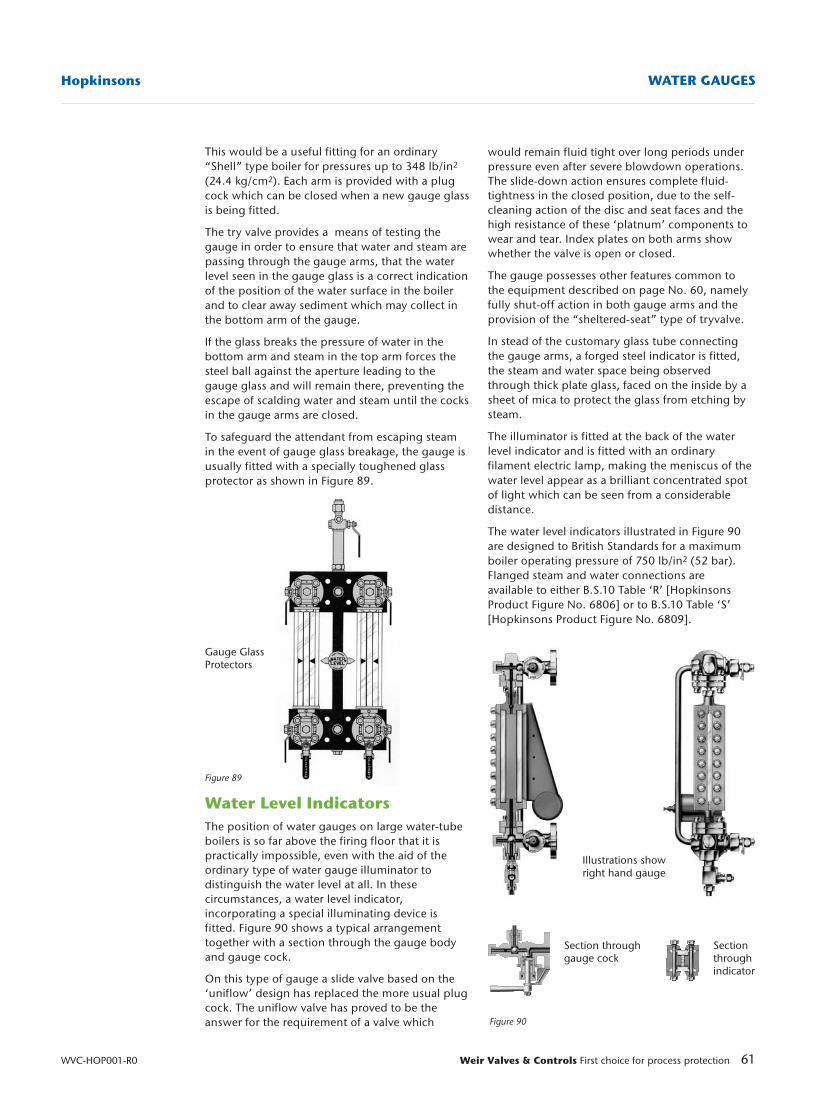
This would be a useful fitting for an ordinary“Shell” type boiler for pressures up to 348 lb/in2
(24.4 kg/cm2). Each arm is provided with a plugcock which can be closed when a new gauge glassis being fitted.
The try valve provides a means of testing thegauge in order to ensure that water and steam arepassing through the gauge arms, that the waterlevel seen in the gauge glass is a correct indicationof the position of the water surface in the boilerand to clear away sediment which may collect inthe bottom arm of the gauge.
If the glass breaks the pressure of water in thebottom arm and steam in the top arm forces thesteel ball against the aperture leading to thegauge glass and will remain there, preventing theescape of scalding water and steam until the cocksin the gauge arms are closed.
To safeguard the attendant from escaping steamin the event of gauge glass breakage, the gauge isusually fitted with a specially toughened glassprotector as shown in Figure 89.
Water Level IndicatorsThe position of water gauges on large water-tubeboilers is so far above the firing floor that it ispractically impossible, even with the aid of theordinary type of water gauge illuminator todistinguish the water level at all. In thesecircumstances, a water level indicator,incorporating a special illuminating device isfitted. Figure 90 shows a typical arrangementtogether with a section through the gauge bodyand gauge cock.
On this type of gauge a slide valve based on the‘uniflow’ design has replaced the more usual plugcock. The uniflow valve has proved to be theanswer for the requirement of a valve which
Figure 89
61Weir Valves & Controls First choice for process protection
Hopkinsons WATER GAUGES
WVC-HOP001-R0
Figure 90
would remain fluid tight over long periods underpressure even after severe blowdown operations.The slide-down action ensures complete fluid-tightness in the closed position, due to the self-cleaning action of the disc and seat faces and thehigh resistance of these ‘platnum’ components towear and tear. Index plates on both arms showwhether the valve is open or closed.
The gauge possesses other features common tothe equipment described on page No. 60, namelyfully shut-off action in both gauge arms and theprovision of the “sheltered-seat” type of tryvalve.
In stead of the customary glass tube connectingthe gauge arms, a forged steel indicator is fitted,the steam and water space being observedthrough thick plate glass, faced on the inside by asheet of mica to protect the glass from etching bysteam.
The illuminator is fitted at the back of the waterlevel indicator and is fitted with an ordinaryfilament electric lamp, making the meniscus of thewater level appear as a brilliant concentrated spotof light which can be seen from a considerabledistance.
The water level indicators illustrated in Figure 90are designed to British Standards for a maximumboiler operating pressure of 750 lb/in2 (52 bar).Flanged steam and water connections areavailable to either B.S.10 Table ‘R’ [HopkinsonsProduct Figure No. 6806] or to B.S.10 Table ‘S’[Hopkinsons Product Figure No. 6809].
Illustrations showright hand gauge
Section throughgauge cock
Sectionthroughindicator
Gauge GlassProtectors
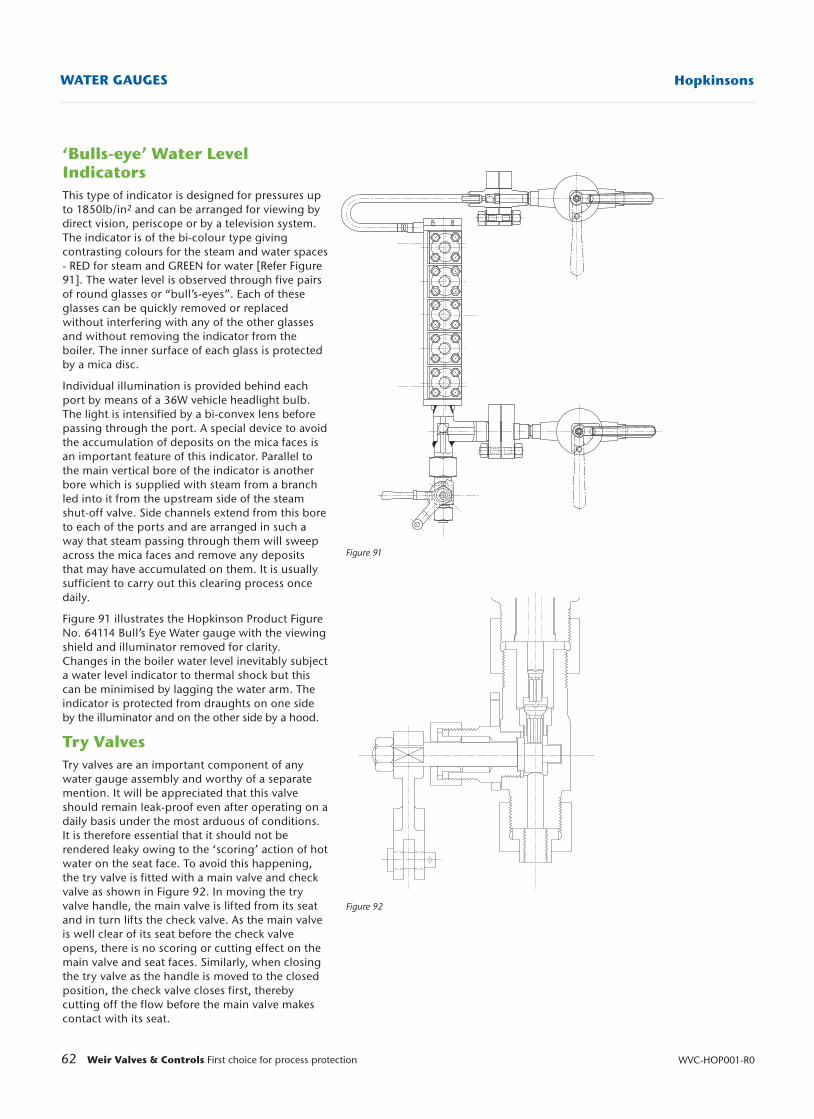
62 Weir Valves & Controls First choice for process protection WVC-HOP001-R0
HopkinsonsWATER GAUGES
OPEN
SH
UT
Figure 91
Figure 92
‘Bulls-eye’ Water LevelIndicatorsThis type of indicator is designed for pressures upto 1850lb/in2 and can be arranged for viewing bydirect vision, periscope or by a television system.The indicator is of the bi-colour type givingcontrasting colours for the steam and water spaces- RED for steam and GREEN for water [Refer Figure91]. The water level is observed through five pairsof round glasses or “bull’s-eyes”. Each of theseglasses can be quickly removed or replacedwithout interfering with any of the other glassesand without removing the indicator from theboiler. The inner surface of each glass is protectedby a mica disc.
Individual illumination is provided behind eachport by means of a 36W vehicle headlight bulb.The light is intensified by a bi-convex lens beforepassing through the port. A special device to avoidthe accumulation of deposits on the mica faces isan important feature of this indicator. Parallel tothe main vertical bore of the indicator is anotherbore which is supplied with steam from a branchled into it from the upstream side of the steamshut-off valve. Side channels extend from this boreto each of the ports and are arranged in such away that steam passing through them will sweepacross the mica faces and remove any depositsthat may have accumulated on them. It is usuallysufficient to carry out this clearing process oncedaily.
Figure 91 illustrates the Hopkinson Product FigureNo. 64114 Bull’s Eye Water gauge with the viewingshield and illuminator removed for clarity.Changes in the boiler water level inevitably subjecta water level indicator to thermal shock but thiscan be minimised by lagging the water arm. Theindicator is protected from draughts on one sideby the illuminator and on the other side by a hood.
Try ValvesTry valves are an important component of anywater gauge assembly and worthy of a separatemention. It will be appreciated that this valveshould remain leak-proof even after operating on adaily basis under the most arduous of conditions.It is therefore essential that it should not berendered leaky owing to the ‘scoring’ action of hotwater on the seat face. To avoid this happening,the try valve is fitted with a main valve and checkvalve as shown in Figure 92. In moving the tryvalve handle, the main valve is lifted from its seatand in turn lifts the check valve. As the main valveis well clear of its seat before the check valveopens, there is no scoring or cutting effect on themain valve and seat faces. Similarly, when closingthe try valve as the handle is moved to the closedposition, the check valve closes first, therebycutting off the flow before the main valve makescontact with its seat.
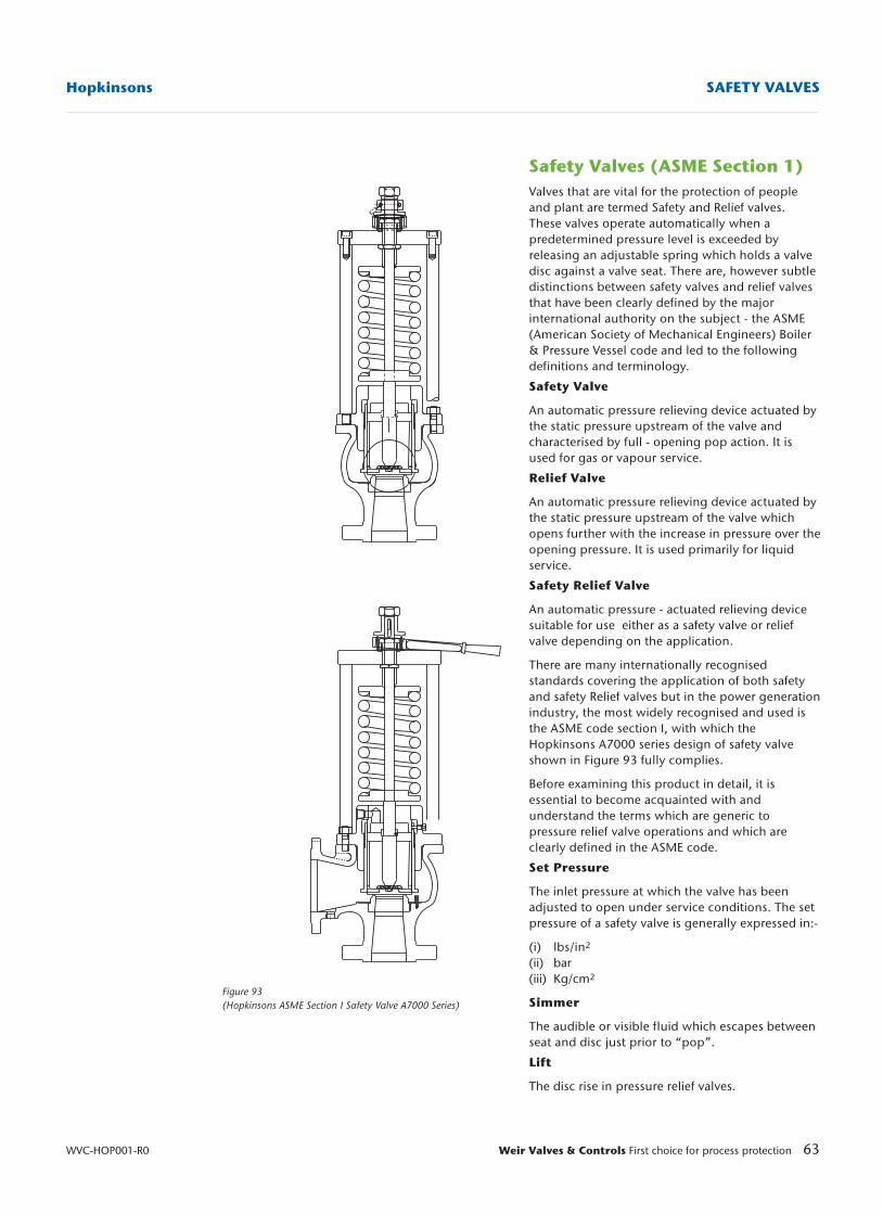
63Weir Valves & Controls First choice for process protection
Hopkinsons SAFETY VALVES
WVC-HOP001-R0
Figure 93(Hopkinsons ASME Section I Safety Valve A7000 Series)
Safety Valves (ASME Section 1)Valves that are vital for the protection of peopleand plant are termed Safety and Relief valves.These valves operate automatically when apredetermined pressure level is exceeded byreleasing an adjustable spring which holds a valvedisc against a valve seat. There are, however subtledistinctions between safety valves and relief valvesthat have been clearly defined by the majorinternational authority on the subject - the ASME(American Society of Mechanical Engineers) Boiler& Pressure Vessel code and led to the followingdefinitions and terminology.
Safety Valve
An automatic pressure relieving device actuated bythe static pressure upstream of the valve andcharacterised by full - opening pop action. It isused for gas or vapour service.
Relief Valve
An automatic pressure relieving device actuated bythe static pressure upstream of the valve whichopens further with the increase in pressure over theopening pressure. It is used primarily for liquidservice.
Safety Relief Valve
An automatic pressure - actuated relieving devicesuitable for use either as a safety valve or reliefvalve depending on the application.
There are many internationally recognisedstandards covering the application of both safetyand safety Relief valves but in the power generationindustry, the most widely recognised and used isthe ASME code section I, with which theHopkinsons A7000 series design of safety valveshown in Figure 93 fully complies.
Before examining this product in detail, it isessential to become acquainted with andunderstand the terms which are generic topressure relief valve operations and which areclearly defined in the ASME code.
Set Pressure
The inlet pressure at which the valve has beenadjusted to open under service conditions. The setpressure of a safety valve is generally expressed in:-
(i) lbs/in2
(ii) bar(iii) Kg/cm2
Simmer
The audible or visible fluid which escapes betweenseat and disc just prior to “pop”.
Lift
The disc rise in pressure relief valves.
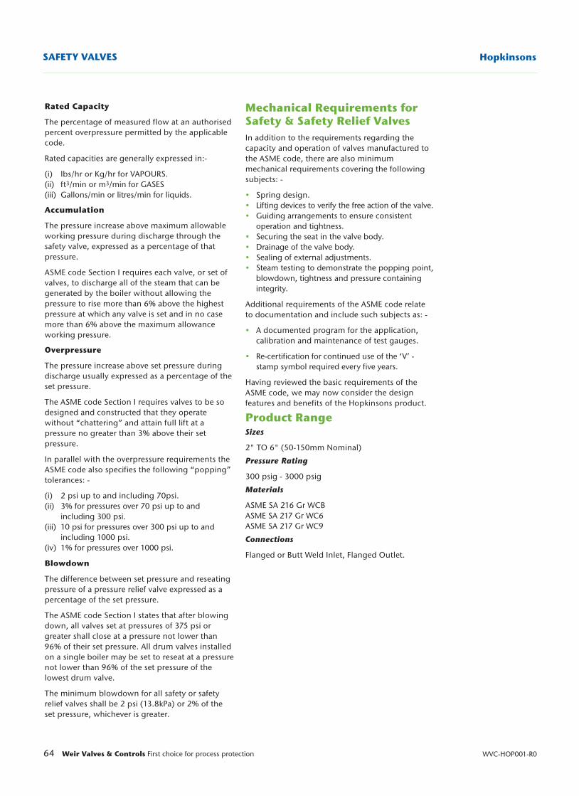
64 Weir Valves & Controls First choice for process protection WVC-HOP001-R0
HopkinsonsSAFETY VALVES
Rated Capacity
The percentage of measured flow at an authorisedpercent overpressure permitted by the applicablecode.
Rated capacities are generally expressed in:-
(i) lbs/hr or Kg/hr for VAPOURS.(ii) ft3/min or m3/min for GASES(iii) Gallons/min or litres/min for liquids.
Accumulation
The pressure increase above maximum allowableworking pressure during discharge through thesafety valve, expressed as a percentage of thatpressure.
ASME code Section I requires each valve, or set ofvalves, to discharge all of the steam that can begenerated by the boiler without allowing thepressure to rise more than 6% above the highestpressure at which any valve is set and in no casemore than 6% above the maximum allowanceworking pressure.
Overpressure
The pressure increase above set pressure duringdischarge usually expressed as a percentage of theset pressure.
The ASME code Section I requires valves to be sodesigned and constructed that they operatewithout “chattering” and attain full lift at apressure no greater than 3% above their setpressure.
In parallel with the overpressure requirements theASME code also specifies the following “popping”tolerances: -
(i) 2 psi up to and including 70psi.(ii) 3% for pressures over 70 psi up to and
including 300 psi.(iii) 10 psi for pressures over 300 psi up to and
including 1000 psi.(iv) 1% for pressures over 1000 psi.
Blowdown
The difference between set pressure and reseatingpressure of a pressure relief valve expressed as apercentage of the set pressure.
The ASME code Section I states that after blowingdown, all valves set at pressures of 375 psi orgreater shall close at a pressure not lower than96% of their set pressure. All drum valves installedon a single boiler may be set to reseat at a pressurenot lower than 96% of the set pressure of thelowest drum valve.
The minimum blowdown for all safety or safetyrelief valves shall be 2 psi (13.8kPa) or 2% of theset pressure, whichever is greater.
Mechanical Requirements forSafety & Safety Relief ValvesIn addition to the requirements regarding thecapacity and operation of valves manufactured tothe ASME code, there are also minimummechanical requirements covering the followingsubjects: -
• Spring design.• Lifting devices to verify the free action of the valve.• Guiding arrangements to ensure consistent
operation and tightness.• Securing the seat in the valve body.• Drainage of the valve body.• Sealing of external adjustments.• Steam testing to demonstrate the popping point,
blowdown, tightness and pressure containing integrity.
Additional requirements of the ASME code relateto documentation and include such subjects as: -
• A documented program for the application, calibration and maintenance of test gauges.
• Re-certification for continued use of the ‘V’ - stamp symbol required every five years.
Having reviewed the basic requirements of theASME code, we may now consider the designfeatures and benefits of the Hopkinsons product.
Product RangeSizes
2" TO 6" (50-150mm Nominal)
Pressure Rating
300 psig - 3000 psig
Materials
ASME SA 216 Gr WCBASME SA 217 Gr WC6ASME SA 217 Gr WC9
Connections
Flanged or Butt Weld Inlet, Flanged Outlet.
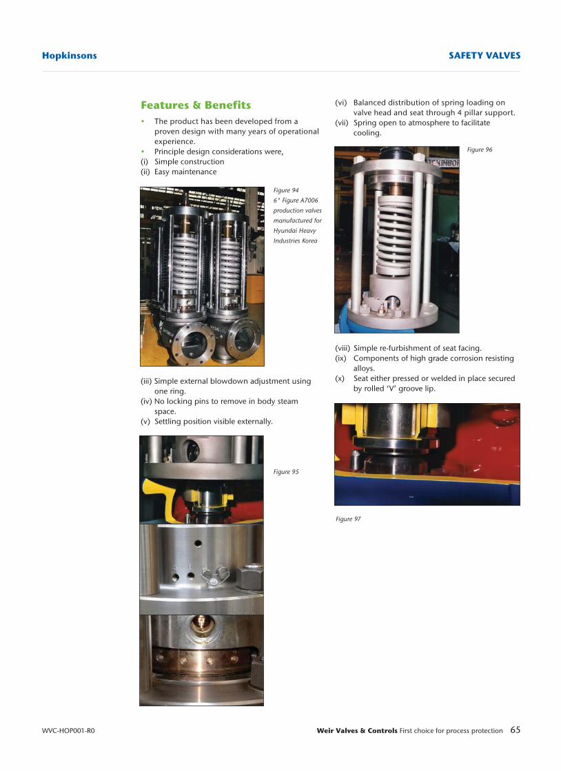
Features & Benefits• The product has been developed from a
proven design with many years of operational experience.
• Principle design considerations were, (i) Simple construction(ii) Easy maintenance
(iii) Simple external blowdown adjustment using one ring.
(iv) No locking pins to remove in body steam space.
(v) Settling position visible externally.
65Weir Valves & Controls First choice for process protection
Hopkinsons SAFETY VALVES
WVC-HOP001-R0
(vi) Balanced distribution of spring loading on valve head and seat through 4 pillar support.
(vii) Spring open to atmosphere to facilitate cooling.
(viii) Simple re-furbishment of seat facing.(ix) Components of high grade corrosion resisting
alloys.(x) Seat either pressed or welded in place secured
by rolled ‘V’ groove lip.
Figure 94
6" Figure A7006
production valves
manufactured for
Hyundai Heavy
Industries Korea
Figure 95
Figure 96
Figure 97
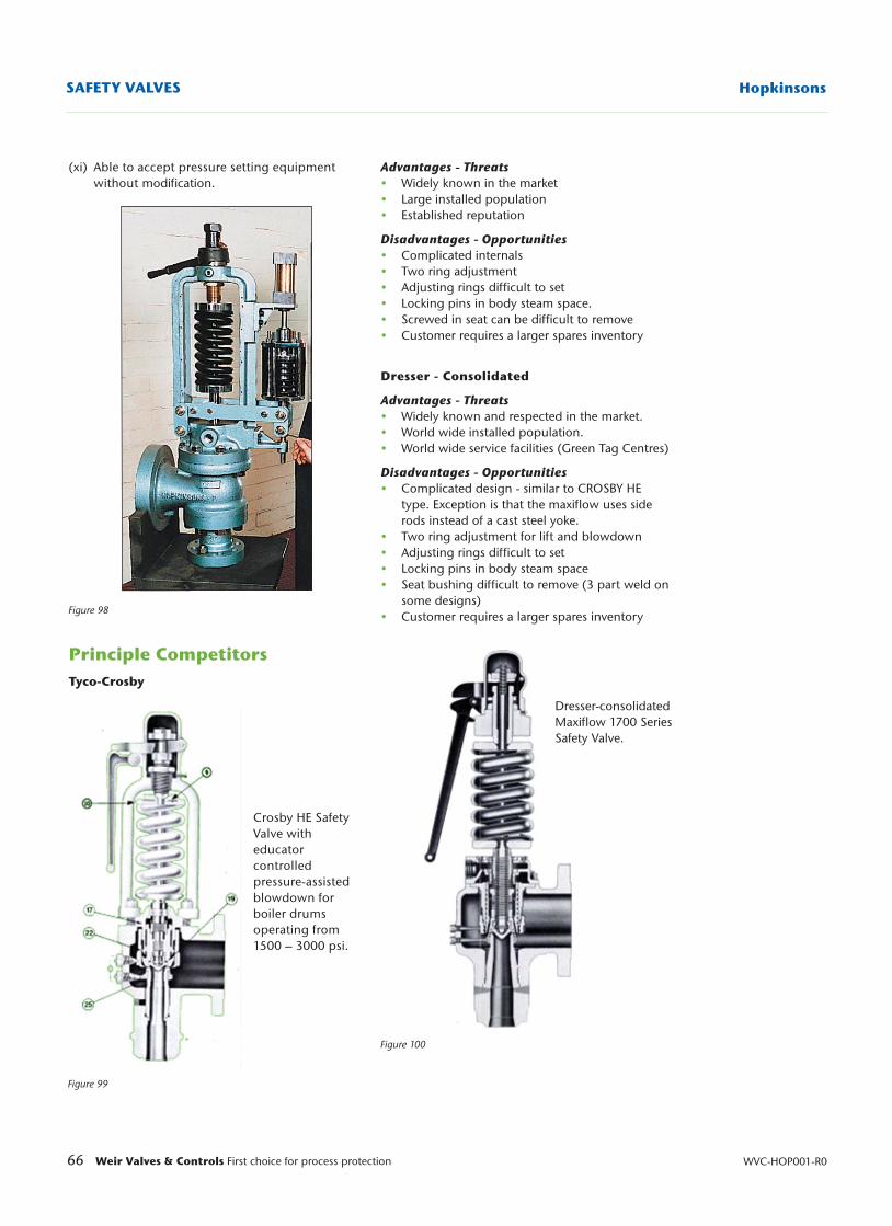
Advantages - Threats• Widely known in the market• Large installed population• Established reputation
Disadvantages - Opportunities• Complicated internals• Two ring adjustment• Adjusting rings difficult to set• Locking pins in body steam space.• Screwed in seat can be difficult to remove • Customer requires a larger spares inventory
Dresser - Consolidated
Advantages - Threats• Widely known and respected in the market.• World wide installed population.• World wide service facilities (Green Tag Centres)
Disadvantages - Opportunities• Complicated design - similar to CROSBY HE
type. Exception is that the maxiflow uses side rods instead of a cast steel yoke.
• Two ring adjustment for lift and blowdown • Adjusting rings difficult to set• Locking pins in body steam space• Seat bushing difficult to remove (3 part weld on
some designs)• Customer requires a larger spares inventory
66 Weir Valves & Controls First choice for process protection WVC-HOP001-R0
HopkinsonsSAFETY VALVES
(xi) Able to accept pressure setting equipment without modification.
Principle CompetitorsTyco-Crosby
Figure 98
Figure 99
Figure 100
Crosby HE SafetyValve witheducatorcontrolledpressure-assistedblowdown forboiler drumsoperating from1500 – 3000 psi.
Dresser-consolidatedMaxiflow 1700 SeriesSafety Valve.
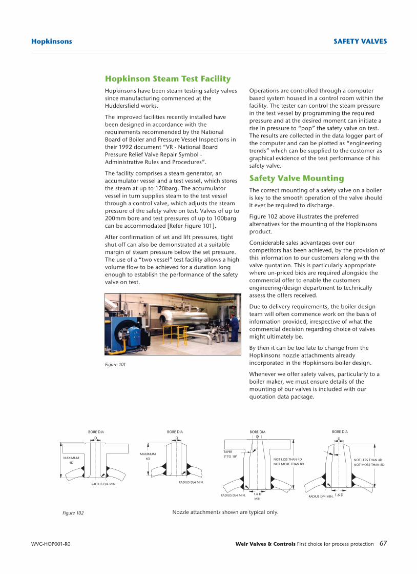
67Weir Valves & Controls First choice for process protection
Hopkinsons SAFETY VALVES
WVC-HOP001-R0
Figure 102
Figure 101
BORE DIA BORE DIA BORE DIA
Nozzle attachments shown are typical only.
RADIUS D/4 MIN.
RADIUS D/4 MIN.
MAXIMUM4D
TAPER50 TO 100
NOT LESS THAN 4DNOT MORE THAN 8D
NOT LESS THAN 4DNOT MORE THAN 8D
D
BORE DIA
RADIUS D/4 MIN.
MAXIMUM4D
D DD
1.6 DMIN
1.6 DRADIUS D/4 MIN.
Hopkinson Steam Test FacilityHopkinsons have been steam testing safety valvessince manufacturing commenced at theHuddersfield works.
The improved facilities recently installed havebeen designed in accordance with therequirements recommended by the NationalBoard of Boiler and Pressure Vessel Inspections intheir 1992 document “VR - National BoardPressure Relief Valve Repair Symbol -Administrative Rules and Procedures”.
The facility comprises a steam generator, anaccumulator vessel and a test vessel, which storesthe steam at up to 120barg. The accumulatorvessel in turn supplies steam to the test vesselthrough a control valve, which adjusts the steampressure of the safety valve on test. Valves of up to200mm bore and test pressures of up to 100bargcan be accommodated [Refer Figure 101].
After confirmation of set and lift pressures, tightshut off can also be demonstrated at a suitablemargin of steam pressure below the set pressure.The use of a “two vessel” test facility allows a highvolume flow to be achieved for a duration longenough to establish the performance of the safetyvalve on test.
Operations are controlled through a computerbased system housed in a control room within thefacility. The tester can control the steam pressurein the test vessel by programming the requiredpressure and at the desired moment can initiate arise in pressure to “pop” the safety valve on test.The results are collected in the data logger part ofthe computer and can be plotted as “engineeringtrends” which can be supplied to the customer asgraphical evidence of the test performance of hissafety valve.
Safety Valve MountingThe correct mounting of a safety valve on a boileris key to the smooth operation of the valve shouldit ever be required to discharge.
Figure 102 above illustrates the preferredalternatives for the mounting of the Hopkinsonsproduct.
Considerable sales advantages over ourcompetitors has been achieved, by the provision ofthis information to our customers along with thevalve quotation. This is particularly appropriatewhere un-priced bids are required alongside thecommercial offer to enable the customersengineering/design department to technicallyassess the offers received.
Due to delivery requirements, the boiler designteam will often commence work on the basis ofinformation provided, irrespective of what thecommercial decision regarding choice of valvesmight ultimately be.
By then it can be too late to change from theHopkinsons nozzle attachments alreadyincorporated in the Hopkinsons boiler design.
Whenever we offer safety valves, particularly to aboiler maker, we must ensure details of themounting of our valves is included with ourquotation data package.
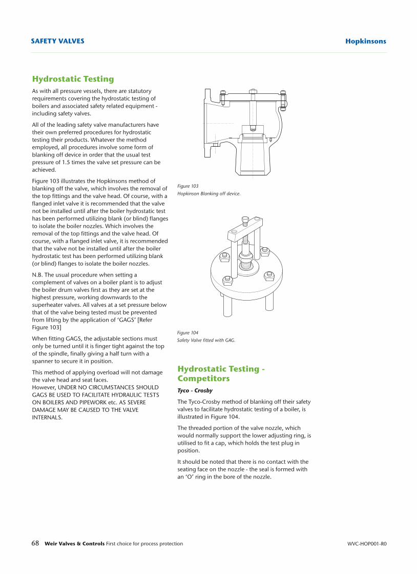
68 Weir Valves & Controls First choice for process protection WVC-HOP001-R0
HopkinsonsSAFETY VALVES
Figure 104
Safety Valve fitted with GAG.
Figure 103
Hopkinson Blanking off device.
Hydrostatic TestingAs with all pressure vessels, there are statutoryrequirements covering the hydrostatic testing ofboilers and associated safety related equipment -including safety valves.
All of the leading safety valve manufacturers havetheir own preferred procedures for hydrostatictesting their products. Whatever the methodemployed, all procedures involve some form ofblanking off device in order that the usual testpressure of 1.5 times the valve set pressure can beachieved.
Figure 103 illustrates the Hopkinsons method ofblanking off the valve, which involves the removal ofthe top fittings and the valve head. Of course, with aflanged inlet valve it is recommended that the valvenot be installed until after the boiler hydrostatic testhas been performed utilizing blank (or blind) flangesto isolate the boiler nozzles. Which involves theremoval of the top fittings and the valve head. Ofcourse, with a flanged inlet valve, it is recommendedthat the valve not be installed until after the boilerhydrostatic test has been performed utilizing blank(or blind) flanges to isolate the boiler nozzles.
N.B. The usual procedure when setting acomplement of valves on a boiler plant is to adjustthe boiler drum valves first as they are set at thehighest pressure, working downwards to thesuperheater valves. All valves at a set pressure belowthat of the valve being tested must be preventedfrom lifting by the application of ‘GAGS’ [ReferFigure 103]
When fitting GAGS, the adjustable sections mustonly be turned until it is finger tight against the topof the spindle, finally giving a half turn with aspanner to secure it in position.
This method of applying overload will not damagethe valve head and seat faces.However, UNDER NO CIRCUMSTANCES SHOULDGAGS BE USED TO FACILITATE HYDRAULIC TESTSON BOILERS AND PIPEWORK etc. AS SEVEREDAMAGE MAY BE CAUSED TO THE VALVEINTERNALS.
Hydrostatic Testing -CompetitorsTyco - Crosby
The Tyco-Crosby method of blanking off their safetyvalves to facilitate hydrostatic testing of a boiler, isillustrated in Figure 104.
The threaded portion of the valve nozzle, whichwould normally support the lower adjusting ring, isutilised to fit a cap, which holds the test plug inposition.
It should be noted that there is no contact with theseating face on the nozzle - the seal is formed withan ‘O’ ring in the bore of the nozzle.
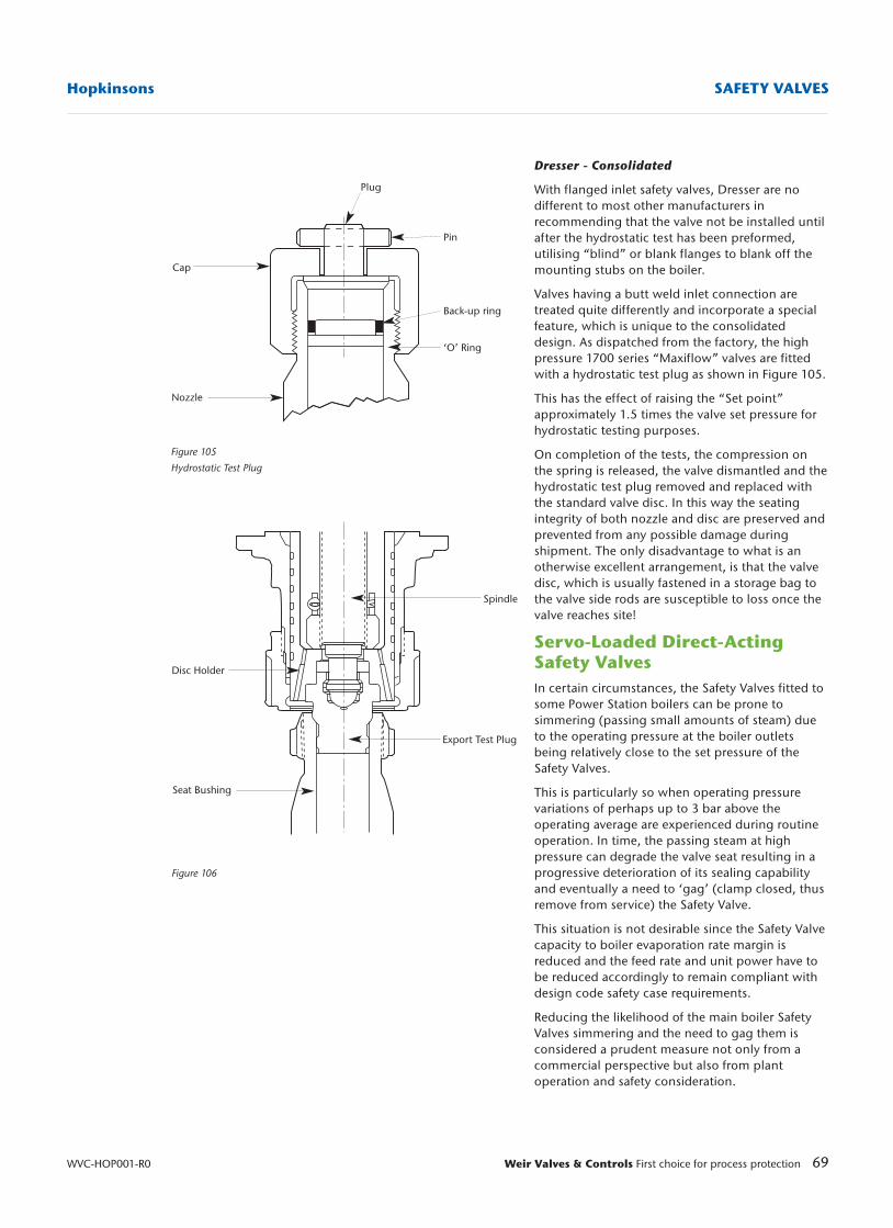
69Weir Valves & Controls First choice for process protection
Hopkinsons SAFETY VALVES
WVC-HOP001-R0
Figure 106
Figure 105
Hydrostatic Test Plug
Pin
Back-up ring
‘O’ Ring
Plug
Cap
Nozzle
Seat Bushing
Export Test Plug
Disc Holder
Spindle
Dresser - Consolidated
With flanged inlet safety valves, Dresser are nodifferent to most other manufacturers inrecommending that the valve not be installed untilafter the hydrostatic test has been preformed,utilising “blind” or blank flanges to blank off themounting stubs on the boiler.
Valves having a butt weld inlet connection aretreated quite differently and incorporate a specialfeature, which is unique to the consolidateddesign. As dispatched from the factory, the highpressure 1700 series “Maxiflow” valves are fittedwith a hydrostatic test plug as shown in Figure 105.
This has the effect of raising the “Set point”approximately 1.5 times the valve set pressure forhydrostatic testing purposes.
On completion of the tests, the compression onthe spring is released, the valve dismantled and thehydrostatic test plug removed and replaced withthe standard valve disc. In this way the seatingintegrity of both nozzle and disc are preserved andprevented from any possible damage duringshipment. The only disadvantage to what is anotherwise excellent arrangement, is that the valvedisc, which is usually fastened in a storage bag tothe valve side rods are susceptible to loss once thevalve reaches site!
Servo-Loaded Direct-ActingSafety ValvesIn certain circumstances, the Safety Valves fitted tosome Power Station boilers can be prone tosimmering (passing small amounts of steam) dueto the operating pressure at the boiler outletsbeing relatively close to the set pressure of theSafety Valves.
This is particularly so when operating pressurevariations of perhaps up to 3 bar above theoperating average are experienced during routineoperation. In time, the passing steam at highpressure can degrade the valve seat resulting in aprogressive deterioration of its sealing capabilityand eventually a need to ‘gag’ (clamp closed, thusremove from service) the Safety Valve.
This situation is not desirable since the Safety Valvecapacity to boiler evaporation rate margin isreduced and the feed rate and unit power have tobe reduced accordingly to remain compliant withdesign code safety case requirements.
Reducing the likelihood of the main boiler SafetyValves simmering and the need to gag them isconsidered a prudent measure not only from acommercial perspective but also from plantoperation and safety consideration.
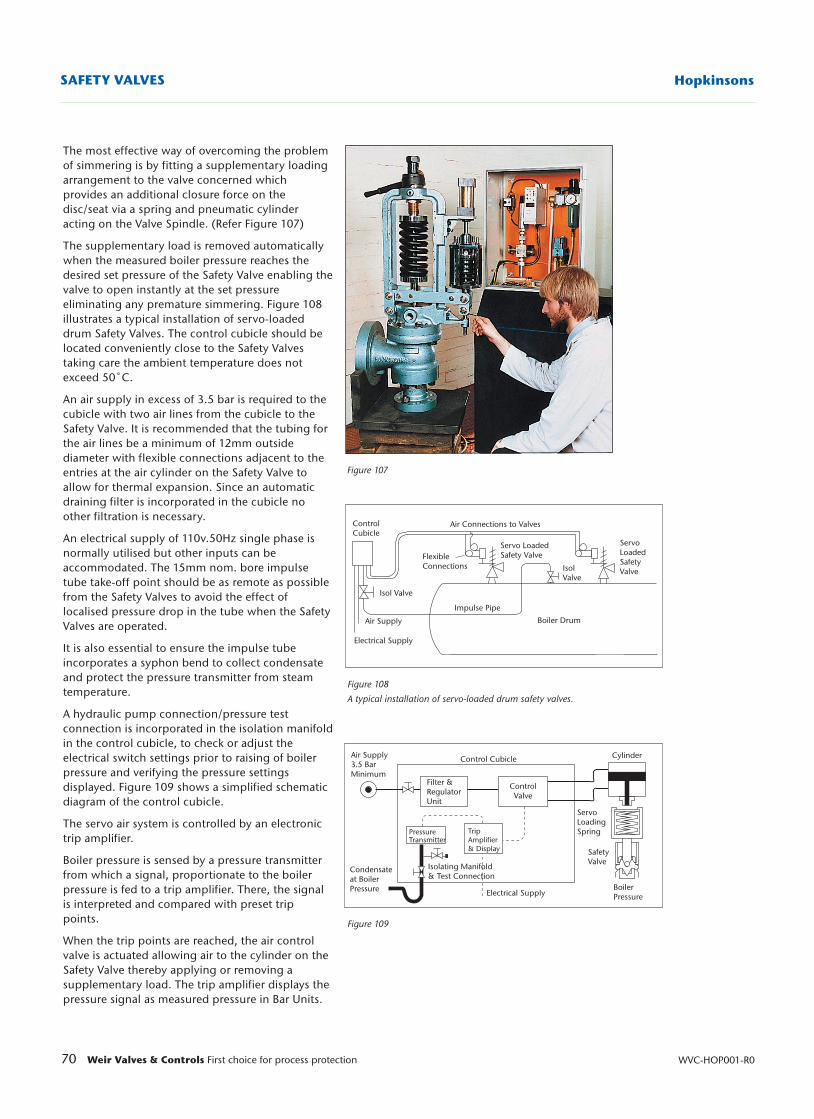
70 Weir Valves & Controls First choice for process protection WVC-HOP001-R0
HopkinsonsSAFETY VALVES
Figure 108
A typical installation of servo-loaded drum safety valves.
Figure 109
Figure 107
Air Connections to Valves
Servo LoadedSafety Valve
Servo LoadedSafety Valve
IsolValve
Boiler Drum
Impulse Pipe
FlexibleConnections
ControlCubicle
Air Supply
Electrical Supply
Isol Valve
Control Cubicle Cylinder
ControlValve
ServoLoadingSpring
SafetyValve
BoilerPressureElectrical Supply
Trip Amplifier& Display
Filter &RegulatorUnit
PressureTransmitter
Isolating Manifold& Test Connection
Condensateat BoilerPressure
Air Supply3.5 BarMinimum
The most effective way of overcoming the problemof simmering is by fitting a supplementary loadingarrangement to the valve concerned whichprovides an additional closure force on thedisc/seat via a spring and pneumatic cylinderacting on the Valve Spindle. (Refer Figure 107)
The supplementary load is removed automaticallywhen the measured boiler pressure reaches thedesired set pressure of the Safety Valve enabling thevalve to open instantly at the set pressureeliminating any premature simmering. Figure 108illustrates a typical installation of servo-loadeddrum Safety Valves. The control cubicle should belocated conveniently close to the Safety Valvestaking care the ambient temperature does notexceed 50˚C.
An air supply in excess of 3.5 bar is required to thecubicle with two air lines from the cubicle to theSafety Valve. It is recommended that the tubing forthe air lines be a minimum of 12mm outsidediameter with flexible connections adjacent to theentries at the air cylinder on the Safety Valve toallow for thermal expansion. Since an automaticdraining filter is incorporated in the cubicle noother filtration is necessary.
An electrical supply of 110v.50Hz single phase isnormally utilised but other inputs can beaccommodated. The 15mm nom. bore impulsetube take-off point should be as remote as possiblefrom the Safety Valves to avoid the effect oflocalised pressure drop in the tube when the SafetyValves are operated.
It is also essential to ensure the impulse tubeincorporates a syphon bend to collect condensateand protect the pressure transmitter from steamtemperature.
A hydraulic pump connection/pressure testconnection is incorporated in the isolation manifoldin the control cubicle, to check or adjust theelectrical switch settings prior to raising of boilerpressure and verifying the pressure settingsdisplayed. Figure 109 shows a simplified schematicdiagram of the control cubicle.
The servo air system is controlled by an electronictrip amplifier.
Boiler pressure is sensed by a pressure transmitterfrom which a signal, proportionate to the boilerpressure is fed to a trip amplifier. There, the signalis interpreted and compared with preset trippoints.
When the trip points are reached, the air controlvalve is actuated allowing air to the cylinder on theSafety Valve thereby applying or removing asupplementary load. The trip amplifier displays thepressure signal as measured pressure in Bar Units.
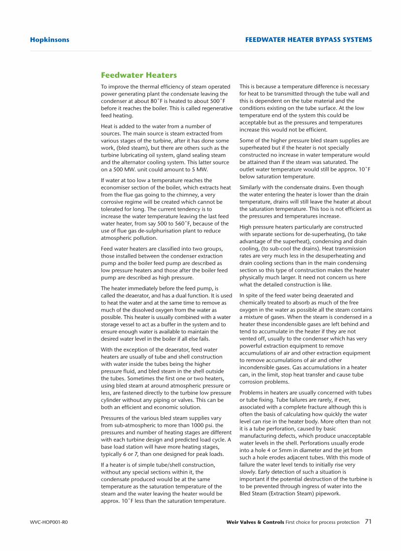
71Weir Valves & Controls First choice for process protection
Hopkinsons FEEDWATER HEATER BYPASS SYSTEMS
WVC-HOP001-R0
Feedwater HeatersTo improve the thermal efficiency of steam operatedpower generating plant the condensate leaving thecondenser at about 80˚F is heated to about 500˚Fbefore it reaches the boiler. This is called regenerativefeed heating.
Heat is added to the water from a number ofsources. The main source is steam extracted fromvarious stages of the turbine, after it has done somework, (bled steam), but there are others such as theturbine lubricating oil system, gland sealing steamand the alternator cooling system. This latter sourceon a 500 MW. unit could amount to 5 MW.
If water at too low a temperature reaches theeconomiser section of the boiler, which extracts heatfrom the flue gas going to the chimney, a verycorrosive regime will be created which cannot betolerated for long. The current tendency is toincrease the water temperature leaving the last feedwater heater, from say 500 to 560˚F, because of theuse of flue gas de-sulphurisation plant to reduceatmospheric pollution.
Feed water heaters are classified into two groups,those installed between the condenser extractionpump and the boiler feed pump are described aslow pressure heaters and those after the boiler feedpump are described as high pressure.
The heater immediately before the feed pump, iscalled the deaerator, and has a dual function. It is usedto heat the water and at the same time to remove asmuch of the dissolved oxygen from the water aspossible. This heater is usually combined with a waterstorage vessel to act as a buffer in the system and toensure enough water is available to maintain thedesired water level in the boiler if all else fails.
With the exception of the deaerator, feed waterheaters are usually of tube and shell constructionwith water inside the tubes being the higherpressure fluid, and bled steam in the shell outsidethe tubes. Sometimes the first one or two heaters,using bled steam at around atmospheric pressure orless, are fastened directly to the turbine low pressurecylinder without any piping or valves. This can beboth an efficient and economic solution.
Pressures of the various bled steam supplies varyfrom sub-atmospheric to more than 1000 psi. thepressures and number of heating stages are differentwith each turbine design and predicted load cycle. Abase load station will have more heating stages,typically 6 or 7, than one designed for peak loads.
If a heater is of simple tube/shell construction,without any special sections within it, thecondensate produced would be at the sametemperature as the saturation temperature of thesteam and the water leaving the heater would beapprox. 10˚F less than the saturation temperature.
This is because a temperature difference is necessaryfor heat to be transmitted through the tube wall andthis is dependent on the tube material and theconditions existing on the tube surface. At the lowtemperature end of the system this could beacceptable but as the pressures and temperaturesincrease this would not be efficient.
Some of the higher pressure bled steam supplies aresuperheated but if the heater is not speciallyconstructed no increase in water temperature wouldbe attained than if the steam was saturated. Theoutlet water temperature would still be approx. 10˚Fbelow saturation temperature.
Similarly with the condensate drains. Even thoughthe water entering the heater is lower than the draintemperature, drains will still leave the heater at aboutthe saturation temperature. This too is not efficient asthe pressures and temperatures increase.
High pressure heaters particularly are constructedwith separate sections for de-superheating, (to takeadvantage of the superheat), condensing and draincooling, (to sub-cool the drains). Heat transmissionrates are very much less in the desuperheating anddrain cooling sections than in the main condensingsection so this type of construction makes the heaterphysically much larger. It need not concern us herewhat the detailed construction is like.
In spite of the feed water being deaerated andchemically treated to absorb as much of the freeoxygen in the water as possible all the steam containsa mixture of gases. When the steam is condensed in aheater these incondensible gases are left behind andtend to accumulate in the heater if they are notvented off, usually to the condenser which has verypowerful extraction equipment to removeaccumulations of air and other extraction equipmentto remove accumulations of air and otherincondensible gases. Gas accumulations in a heatercan, in the limit, stop heat transfer and cause tubecorrosion problems.
Problems in heaters are usually concerned with tubesor tube fixing. Tube failures are rarely, if ever,associated with a complete fracture although this isoften the basis of calculating how quickly the waterlevel can rise in the heater body. More often than notit is a tube perforation, caused by basicmanufacturing defects, which produce unacceptablewater levels in the shell. Perforations usually erodeinto a hole 4 or 5mm in diameter and the jet fromsuch a hole erodes adjacent tubes. With this mode offailure the water level tends to initially rise veryslowly. Early detection of such a situation isimportant if the potential destruction of the turbine isto be prevented through ingress of water into theBled Steam (Extraction Steam) pipework.
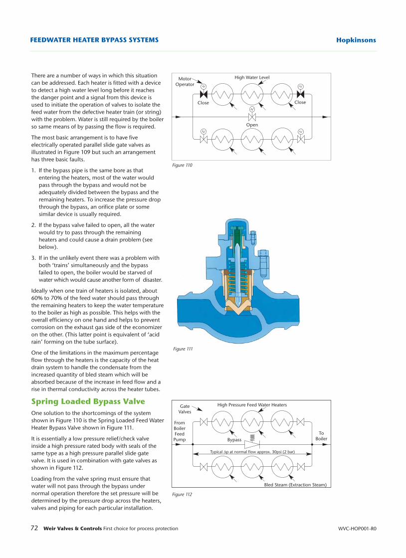
72 Weir Valves & Controls First choice for process protection WVC-HOP001-R0
HopkinsonsFEEDWATER HEATER BYPASS SYSTEMS
High Pressure Feed Water Heaters
Typical ∆p at normal flow approx. 30psi (2 bar)
ToBoiler
GateValves
Figure 110
Figure 112
High Water Level
Open
Close Close
MotorOperator
Bypass
FromBoilerFeed
Pump
Bled Steam (Extraction Steam)
There are a number of ways in which this situationcan be addressed. Each heater is fitted with a deviceto detect a high water level long before it reachesthe danger point and a signal from this device isused to initiate the operation of valves to isolate thefeed water from the defective heater train (or string)with the problem. Water is still required by the boilerso same means of by passing the flow is required.
The most basic arrangement is to have fiveelectrically operated parallel slide gate valves asillustrated in Figure 109 but such an arrangementhas three basic faults.
1. If the bypass pipe is the same bore as that entering the heaters, most of the water would pass through the bypass and would not be adequately divided between the bypass and the remaining heaters. To increase the pressure drop through the bypass, an orifice plate or some similar device is usually required.
2. If the bypass valve failed to open, all the water would try to pass through the remaining heaters and could cause a drain problem (see below).
3. If in the unlikely event there was a problem with both ‘trains’ simultaneously and the bypass failed to open, the boiler would be starved of water which would cause another form of disaster.
Ideally when one train of heaters is isolated, about60% to 70% of the feed water should pass throughthe remaining heaters to keep the water temperatureto the boiler as high as possible. This helps with theoverall efficiency on one hand and helps to preventcorrosion on the exhaust gas side of the economizeron the other. (This latter point is equivalent of ‘acidrain’ forming on the tube surface).
One of the limitations in the maximum percentageflow through the heaters is the capacity of the heatdrain system to handle the condensate from theincreased quantity of bled steam which will beabsorbed because of the increase in feed flow and arise in thermal conductivity across the heater tubes.
Spring Loaded Bypass ValveOne solution to the shortcomings of the systemshown in Figure 110 is the Spring Loaded Feed WaterHeater Bypass Valve shown in Figure 111.
It is essentially a low pressure relief/check valveinside a high pressure rated body with seals of thesame type as a high pressure parallel slide gatevalve. It is used in combination with gate valves asshown in Figure 112.
Loading from the valve spring must ensure thatwater will not pass through the bypass undernormal operation therefore the set pressure will bedetermined by the pressure drop across the heaters,valves and piping for each particular installation.
Figure 111
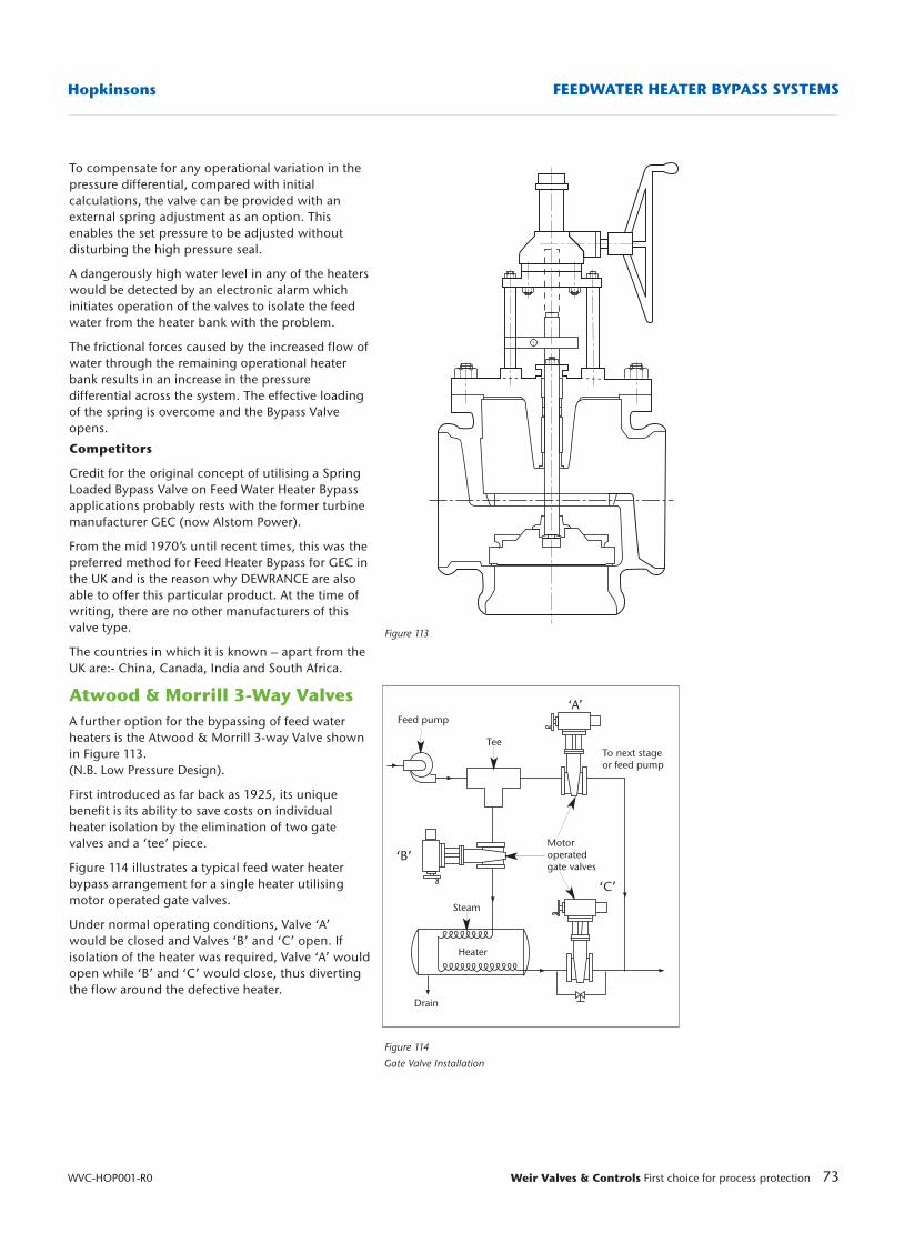
73Weir Valves & Controls First choice for process protection
Hopkinsons FEEDWATER HEATER BYPASS SYSTEMS
WVC-HOP001-R0
Figure 113
Figure 114
Gate Valve Installation
Feed pump
TeeTo next stageor feed pump
Motoroperatedgate valves
Steam
Drain
‘A’
‘C’
‘B’
Heater
To compensate for any operational variation in thepressure differential, compared with initialcalculations, the valve can be provided with anexternal spring adjustment as an option. Thisenables the set pressure to be adjusted withoutdisturbing the high pressure seal.
A dangerously high water level in any of the heaterswould be detected by an electronic alarm whichinitiates operation of the valves to isolate the feedwater from the heater bank with the problem.
The frictional forces caused by the increased flow ofwater through the remaining operational heaterbank results in an increase in the pressuredifferential across the system. The effective loadingof the spring is overcome and the Bypass Valveopens.
Competitors
Credit for the original concept of utilising a SpringLoaded Bypass Valve on Feed Water Heater Bypassapplications probably rests with the former turbinemanufacturer GEC (now Alstom Power).
From the mid 1970’s until recent times, this was thepreferred method for Feed Heater Bypass for GEC inthe UK and is the reason why DEWRANCE are alsoable to offer this particular product. At the time ofwriting, there are no other manufacturers of thisvalve type.
The countries in which it is known – apart from theUK are:- China, Canada, India and South Africa.
Atwood & Morrill 3-Way ValvesA further option for the bypassing of feed waterheaters is the Atwood & Morrill 3-way Valve shownin Figure 113. (N.B. Low Pressure Design).
First introduced as far back as 1925, its uniquebenefit is its ability to save costs on individualheater isolation by the elimination of two gatevalves and a ‘tee’ piece.
Figure 114 illustrates a typical feed water heaterbypass arrangement for a single heater utilisingmotor operated gate valves.
Under normal operating conditions, Valve ‘A’would be closed and Valves ‘B’ and ‘C’ open. Ifisolation of the heater was required, Valve ‘A’ wouldopen while ‘B’ and ‘C’ would close, thus divertingthe flow around the defective heater.
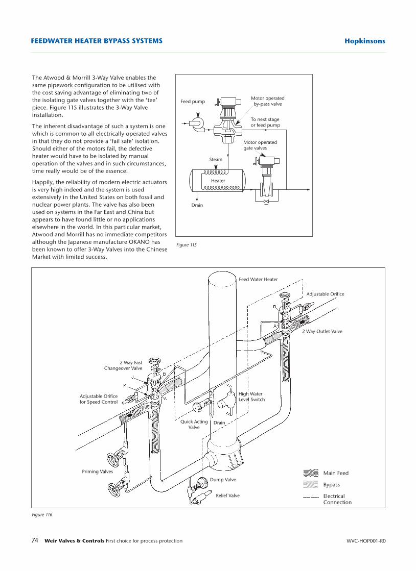
74 Weir Valves & Controls First choice for process protection WVC-HOP001-R0
HopkinsonsFEEDWATER HEATER BYPASS SYSTEMS
Figure 115
Figure 116
Feed pumpMotor operated
by-pass valve
To next stageor feed pump
Motor operatedgate valves
Steam
Drain
Heater
2 Way FastChangeover Valve
Adjustable Orificefor Speed Control
Priming Valves
Relief Valve
Dump Valve
Quick ActingValve
High WaterLevel Switch
Drain
Feed Water Heater
Adjustable Orifice
2 Way Outlet Valve
Main Feed
Bypass
ElectricalConnection
The Atwood & Morrill 3-Way Valve enables thesame pipework configuration to be utilised withthe cost saving advantage of eliminating two ofthe isolating gate valves together with the ‘tee’piece. Figure 115 illustrates the 3-Way Valveinstallation.
The inherent disadvantage of such a system is onewhich is common to all electrically operated valvesin that they do not provide a ‘fail safe’ isolation.Should either of the motors fail, the defectiveheater would have to be isolated by manualoperation of the valves and in such circumstances,time really would be of the essence!
Happily, the reliability of modern electric actuatorsis very high indeed and the system is usedextensively in the United States on both fossil andnuclear power plants. The valve has also beenused on systems in the Far East and China butappears to have found little or no applicationselsewhere in the world. In this particular market,Atwood and Morrill has no immediate competitorsalthough the Japanese manufacture OKANO hasbeen known to offer 3-Way Valves into the ChineseMarket with limited success.
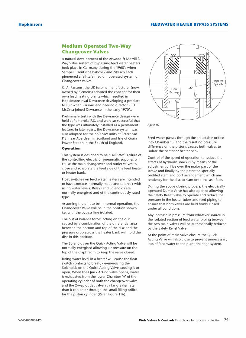
75Weir Valves & Controls First choice for process protection
Hopkinsons FEEDWATER HEATER BYPASS SYSTEMS
WVC-HOP001-R0
Figure 117
Medium Operated Two-WayChangeover ValvesA natural development of the Atwood & Morrill 3-Way Valve system of bypassing feed water heaterstook place in Germany during the 1960’s whenSempell, Deutsche Babcock and Zikesch eachpioneered a fail-safe medium operated system ofChangeover Valves.
C. A. Parsons, the UK turbine manufacturer (nowowned by Siemens) adopted the concept for theirown feed heating plants which resulted inHopkinsons rival Dewrance developing a productto suit when Parsons engineering director R. U.McCrea joined Dewrance in the early 1970’s.
Preliminary tests with the Dewrance design wereheld at Pembroke P.S. and were so successful thatthe type was ultimately installed as a permanentfeature. In later years, the Dewrance system wasalso adopted for the 660 MW units at PeterheadP.S. near Aberdeen in Scotland and Isle of GrainPower Station in the South of England.
Operation
This system is designed to be “Fail Safe”. Failure ofthe controlling electric or pneumatic supplies willcause the main changeover and outlet valves toclose and so isolate the feed side of the feed heateror heater bank.
Float switches on feed water heaters are intendedto have contacts normally made and to break withrising water levels. Relays and Solenoids arenormally energised and of the continuously ratedtype.
Assuming the unit to be in normal operation, theChangeover Valve will be in the position showni.e. with the bypass line isolated.
The out of balance forces acting on the disccaused by a combination of the differential areabetween the bottom and top of the disc and thepressure drop across the heater bank will hold thedisc in this position.
The Solenoids on the Quick Acting Valve will benormally energised allowing air pressure on thetop of the diaphragm to keep the valve closed.
Rising water level in a heater will cause the floatswitch contacts to break, de-energising theSolenoids on the Quick Acting Valve causing it toopen. When the Quick Acting Valve opens, wateris exhausted from the lower Chamber ‘A’ of theoperating cylinder of both the changeover valveand the 2-way outlet valve at a far greater ratethan it can enter through the small filling orificefor the piston cylinder (Refer Figure 116).
Feed water passes through the adjustable orificeinto Chamber ‘B’ and the resulting pressuredifference on the pistons causes both valves toisolate the heater or heater bank.
Control of the speed of operation to reduce theeffects of hydraulic shock is by means of theadjustment orifice over the major part of thestroke and finally by the patented speciallyprofiled stem and port arrangement which anytendency for the disc to slam onto the seat face.
During the above closing process, the electricallyoperated Dump Valve has also opened allowingthe Safety Relief Valve to operate and reduce thepressure in the heater tubes and feed piping toensure that both valves are held firmly closedunder all conditions.
Any increase in pressure from whatever source inthe isolated section of feed water piping betweenthe two main valves will be automatically reducedby the Safety Relief Valve.
At the point of main valve closure the QuickActing Valve will also close to prevent unnecessaryloss of feed water to the plant drainage system.
FlowPassage
TaperedSpindle
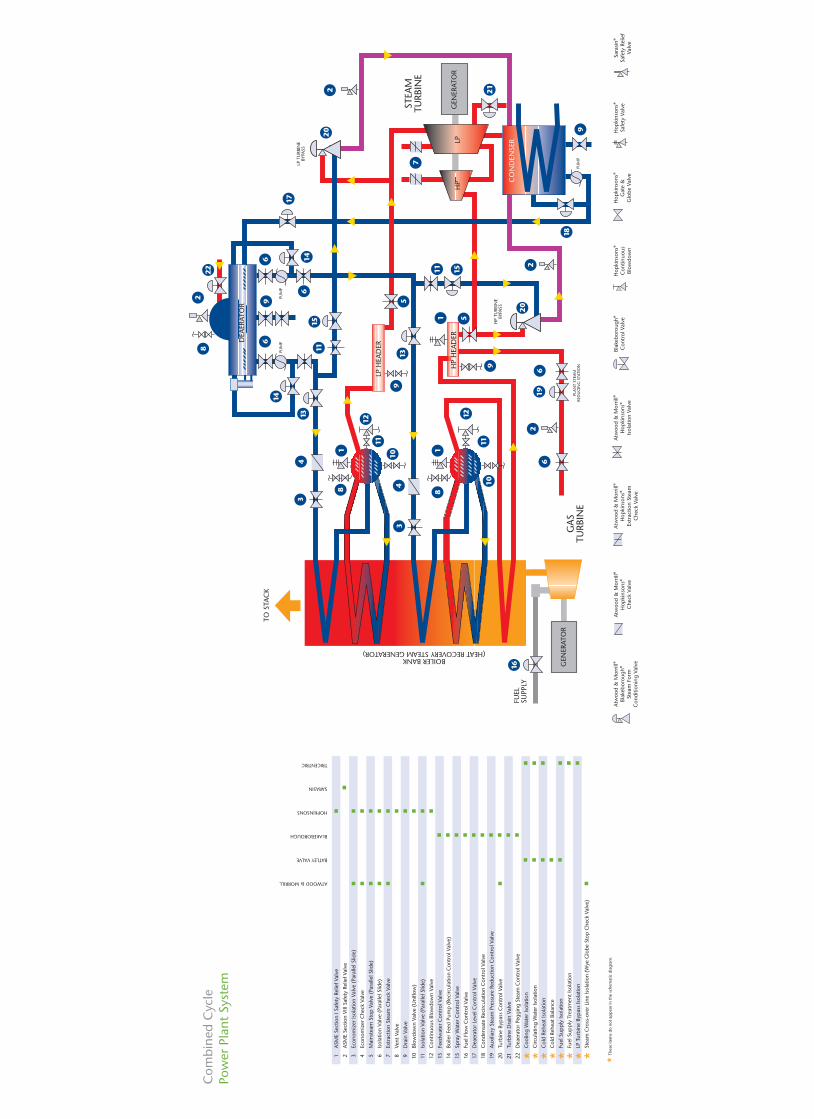
Com
bine
d C
ycle
Pow
er P
lant
Sys
tem
ATWOOD & MORRILL
BATLEY VALVE
BLAKEBOROUGH
HOPKINSONS
SARASIN
TRICENTRIC
■ ■ ■ ■ ■
■ ■ ■ ■ ■ ■ ■ ■ ■ ■
■ ■ ■ ■ ■ ■ ■ ■
■
■ ■ ■ ■ ■ ■ ■ ■ ■ ■ ■
■ ■ ■ ■ ■ ■
1AS
ME
Sect
ion
I Saf
ety
Relie
f Val
ve
2AS
ME
Sect
ion
VIII
Safe
ty R
elie
f Val
ve
3Ec
onom
izer
Isol
atio
n Va
lve
(Par
alle
l Slid
e)
4Ec
onom
izer
Che
ck V
alve
5M
ains
team
Sto
p V
alve
(Pa
ralle
l Slid
e)
6Is
olat
ion
Valv
e (P
aral
lel S
lide)
7Ex
trac
tion
Stea
m C
heck
Val
ve
8Ve
nt V
alve
9D
rain
Val
ve
10Bl
owdo
wn
Valv
e (U
niflo
w)
11Is
olat
ion
Valv
e (P
aral
lel S
lide)
12C
ontin
uous
Blo
wdo
wn
Valv
e
13Fe
edw
ater
Con
trol
Val
ve
14Bo
iler
Feed
Pum
p (
Reci
rcul
atio
n C
ontr
ol V
alve
)
15Sp
ray
Wat
er C
ontr
ol V
alve
16Fu
el F
low
Con
trol
Val
ve
17D
eaer
ator
Lev
el C
ontr
ol V
alve
18C
onde
nsat
e Re
circ
ulat
ion
Con
trol
Val
ve
19Au
xilia
ry S
team
Pre
ssur
e Re
duct
ion
Con
trol
Val
ve
20Tu
rbin
e By
pas
s C
ontr
ol V
alve
21Tu
rbin
e D
rain
Val
ve
22D
eaer
ator
Peg
ging
Ste
am C
ontr
ol V
alve
*C
oolin
g W
ater
Isol
atio
n
*C
ircul
atin
g W
ater
Isol
atio
n
*C
old
Rehe
at Is
olat
ion
*C
old
Rehe
at B
alan
ce
*Fu
el S
upp
ly Is
olat
ion
*Fu
el S
upp
ly T
reat
men
t Iso
latio
n
*LP
Tur
bine
Byp
ass
Isol
atio
n
*St
eam
Cro
ss-o
ver
Line
Isol
atio
n (W
ye G
lobe
Sto
p C
heck
Val
ve)
*Th
ese
item
s do
not
ap
pea
r in
the
sche
mat
ic d
iagr
am.
Hop
kins
ons®
Gat
e &
Glo
be V
alve
Hop
kins
ons®
Con
tinuo
usBl
owdo
wn
Atw
ood
& M
orril
l®H
opki
nson
s®Ex
trac
tion
Stea
mC
heck
Val
ve
Atw
ood
& M
orril
l®H
opki
nson
s®Is
olat
ion
Valv
e
Atw
ood
& M
orril
l®H
opki
nson
s®C
heck
Val
ve
Sara
sin®
Safe
ty R
elie
fVa
lve
Hop
kins
ons®
Safe
ty V
alve
Blak
ebor
ough
®C
ontr
ol V
alve
Atw
ood
& M
orril
l®Bl
akeb
orou
gh®
Stea
m F
orm
Con
ditio
ning
Val
ve
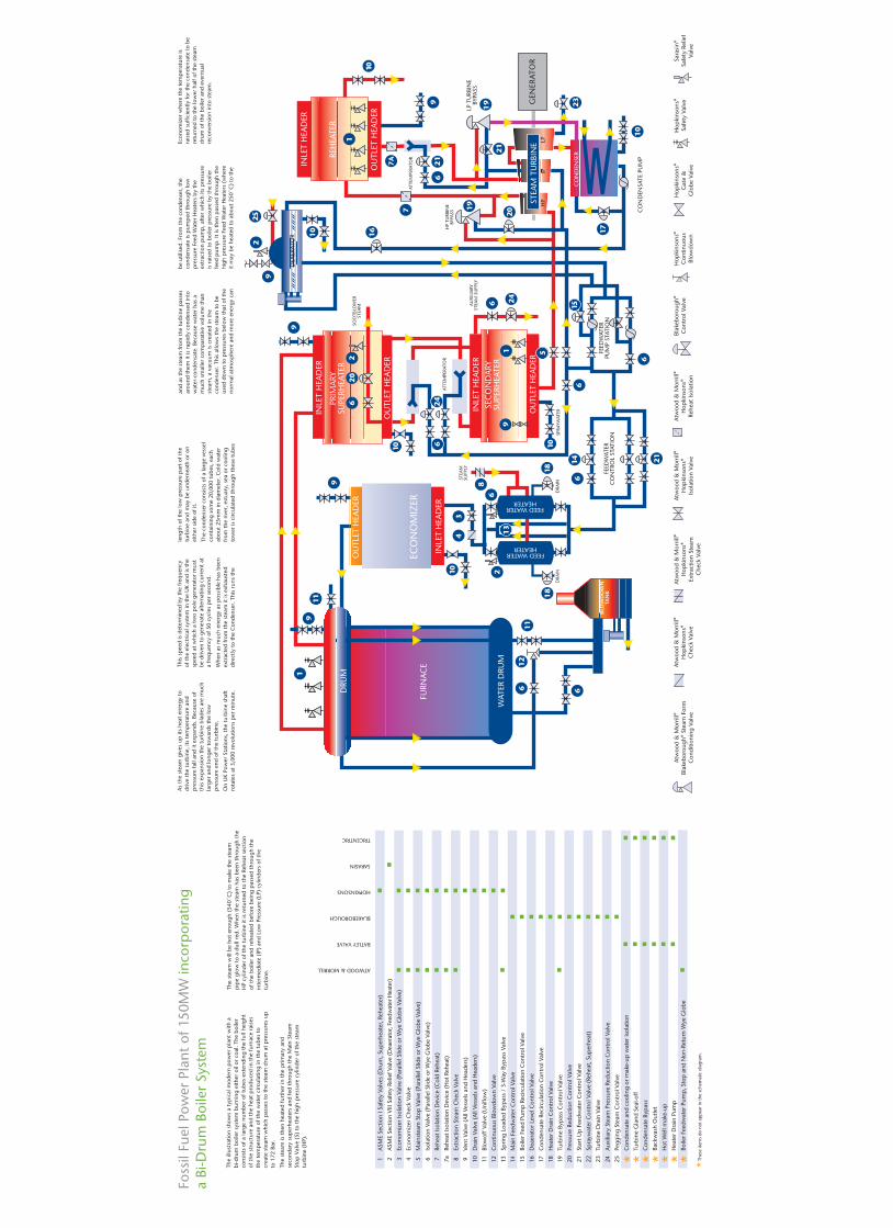
Foss
il Fu
el P
ower
Pla
nt o
f 150
MW
inco
rpor
atin
ga
Bi-D
rum
Boi
ler
Syst
em
ATWOOD & MORRILL
BATLEY VALVE
BLAKEBOROUGH
HOPKINSONS
SARASIN
TRICENTRIC
■ ■ ■ ■ ■ ■
■ ■ ■ ■ ■ ■ ■ ■ ■ ■ ■ ■
■ ■ ■ ■ ■ ■ ■ ■ ■ ■
■
■ ■ ■ ■ ■ ■ ■ ■ ■ ■ ■ ■ ■
■ ■ ■ ■ ■ ■
1AS
ME
Sect
ion
I Saf
ety
Valv
es (
Dru
m, S
uper
heat
er, R
ehea
ter)
2AS
ME
Sect
ion
VIII
Safe
ty R
elie
f Val
ve (
Dea
erat
or, F
eedw
ater
Hea
ter)
3Ec
onom
izer
Isol
atio
n Va
lve
(Par
alle
l Slid
e or
Wye
Glo
be V
alve
)
4Ec
onom
izer
Che
ck V
alve
5M
ains
team
Sto
p V
alve
(Pa
ralle
l Slid
e or
Wye
Glo
be V
alve
)
6Is
olat
ion
Valv
e (P
aral
lel S
lide
or W
ye G
lobe
Val
ve)
7Re
heat
Isol
atio
n D
evic
e (C
old
Rehe
at)
7aRe
heat
Isol
atio
n D
evic
e (H
ot R
ehea
t)
8Ex
trac
tion
Stea
m C
heck
Val
ve
9Ve
nt V
alve
(Al
l Ves
sels
and
Hea
ders
)
10D
rain
Val
ve (
All V
esse
ls a
nd H
eade
rs)
11Bl
owof
f Val
ve (
Uni
flow
)
12C
ontin
uous
Blo
wdo
wn
Valv
e
13Sp
ring
Load
ed B
ypas
s /
3-W
ay B
ypas
s Va
lve
14M
ain
Feed
wat
er C
ontr
ol V
alve
15Bo
iler
Feed
Pum
p R
ecirc
ulat
ion
Con
trol
Val
ve
16D
eaer
ator
Lev
el C
ontr
ol V
alve
17C
onde
nsat
e Re
circ
ulat
ion
Con
trol
Val
ve
18H
eate
r D
rain
Con
trol
Val
ve
19Tu
rbin
e By
pas
s C
ontr
ol V
alve
20Pr
essu
re R
educ
tion
Con
trol
Val
ve
21St
art U
p F
eedw
ater
Con
trol
Val
ve
22Sp
rayw
ater
Con
trol
Val
ve (
Rehe
at, S
uper
heat
)
23Tu
rbin
e D
rain
Val
ve
24Au
xilia
ry S
team
Pre
ssur
e Re
duct
ion
Con
trol
Val
ve
25Pe
ggin
g St
eam
Con
trol
Val
ve
*C
onde
nsat
e an
d co
olin
g or
mak
e-up
wat
er is
olat
ion
*Tu
rbin
e G
land
Sea
l-off
*C
onde
nsat
e By
pas
s
*Ba
ckw
ash
Out
let
*H
ot W
ell m
ake-
up
*H
eate
r D
rain
Pum
p
*Bo
iler
Feed
wat
er P
ump
, Sto
p a
nd N
on-R
etur
n W
ye G
lobe
*Thes
e ite
ms
do n
ot a
pp
ear
in th
e sc
hem
atic
dia
gram
.
Hop
kins
ons®
Gat
e &
Glo
be V
alve
Hop
kins
ons®
Con
tinuo
usBl
owdo
wn
Atw
ood
& M
orril
l®H
opki
nson
s®Ex
trac
tion
Stea
mC
heck
Val
ve
Atw
ood
& M
orril
l®H
opki
nson
s®Is
olat
ion
Valv
e
Atw
ood
& M
orril
l®H
opki
nson
s®Re
heat
Isol
atio
n
Atw
ood
& M
orril
l®H
opki
nson
s®C
heck
Val
ve
Sara
sin®
Safe
ty R
elie
fVa
lve
Hop
kins
ons®
Safe
ty V
alve
Blak
ebor
ough
®C
ontr
ol V
alve
Atw
ood
& M
orril
l®Bl
akeb
orou
gh®
Stea
m F
orm
Con
ditio
ning
Val
ve
The
illus
trat
ion
show
s a
typ
ical
mod
ern
pow
er p
lant
with
abi
-dru
m b
oile
r sy
stem
bur
ning
eith
er o
il or
coa
l. Th
e bo
iler
cons
ists
of a
larg
e nu
mbe
r of
tub
es e
xten
ding
the
full
heig
htof
the
str
uctu
re a
nd t
he h
eat
pro
duce
d in
the
furn
ace
rais
esth
e te
mp
erat
ure
of t
he w
ater
circ
ulat
ing
in t
he t
ubes
to
crea
te s
team
whi
ch p
asse
s to
the
ste
am d
rum
at
pre
ssur
es u
pto
172
Bar
.
The
stea
m is
the
n he
ated
furt
her
in t
he p
rimar
y an
dse
cond
ary
sup
erhe
ater
s an
d fe
d th
roug
h th
e M
ain
Stea
mSt
op V
alve
(5)
to
the
high
pre
ssur
e cy
linde
r of
the
ste
amtu
rbin
e (H
P).
The
stea
m w
ill b
e ho
t en
ough
(54
0˚C
) to
mak
e th
e st
eam
pip
e gl
ow t
o a
dull
red.
Whe
n th
e st
eam
has
bee
n th
roug
h th
eH
P cy
linde
r of
the
tur
bine
it is
ret
urne
d to
the
Reh
eat
sect
ion
of t
he b
oile
r an
d re
heat
ed b
efor
e be
ing
pas
sed
thro
ugh
the
inte
rmed
iate
(IP
) an
d Lo
w P
ress
ure
(LP)
cyl
inde
rs o
f the
turb
ine.
As
the
stea
m g
ives
up
its
heat
ene
rgy
todr
ive
the
turb
ine,
its
tem
per
atur
e an
dp
ress
ure
fall
and
it ex
pan
ds. B
ecau
se o
fth
is e
xpan
sion
the
tur
bine
bla
des
are
muc
hla
rger
and
long
er t
owar
ds t
he lo
wp
ress
ure
end
of t
he t
urbi
ne.
On
UK
Pow
er S
tatio
ns, t
he t
urbi
ne s
haft
rota
tes
at 3
,000
rev
olut
ions
per
min
ute.
This
sp
eed
is d
eter
min
ed b
y th
e fr
eque
ncy
of t
he e
lect
rical
sys
tem
in t
he U
K an
d is
the
spee
d at
whi
ch a
tw
o p
ole
gene
rato
r m
ust
be d
riven
to
gene
rate
alte
rnat
ing
curr
ent
ata
freq
uenc
y of
50
cycl
es p
er s
econ
d.
Whe
n as
muc
h en
ergy
as
pos
sibl
e ha
s be
enex
trac
ted
from
the
ste
am it
is e
xhau
sted
dire
ctly
to
the
Con
dens
er. T
his
runs
the
leng
th o
f the
low
pre
ssur
e p
art
of t
hetu
rbin
e an
d m
ay b
e un
dern
eath
or
onei
ther
sid
e of
it.
The
cond
ense
r co
nsis
ts o
f a la
rge
vess
elco
ntai
ning
som
e 20
,000
tub
es, e
ach
abou
t 25
mm
in d
iam
eter
. Col
d w
ater
from
the
riv
er, e
stua
ry, s
ea o
r co
olin
gto
wer
is c
ircul
ated
thr
ough
the
se t
ubes
and
as t
he s
team
from
the
tur
bine
pas
ses
arou
nd t
hem
it is
rap
idly
con
dens
ed in
tow
ater
-con
dens
ate.
Bec
ause
wat
er h
as a
muc
h sm
alle
r co
mp
arat
ive
volu
me
than
stea
m, a
vac
uum
is c
reat
ed in
the
cond
ense
r. T
his
allo
ws
the
stea
m t
o be
used
dow
n to
pre
ssur
es b
elow
tha
t of
the
norm
al a
tmos
phe
re a
nd m
ore
ener
gy c
an
be u
tilis
ed. F
rom
the
con
dens
er, t
heco
nden
sate
is p
ump
ed t
hrou
gh lo
wp
ress
ure
Feed
Wat
er H
eate
rs b
y th
eex
trac
tion
pum
p, a
fter
whi
ch it
s p
ress
ure
is r
aise
d to
boi
ler
pre
ssur
e by
the
boi
ler
feed
pum
p. I
t is
the
n p
asse
d th
roug
h th
ehi
gh p
ress
ure
Feed
Wat
er H
eate
rs (
whe
reit
may
be
heat
ed t
o ab
out
250˚
C)
to t
he
Econ
omiz
er w
here
the
tem
per
atur
e is
rais
ed s
uffic
ient
ly fo
r th
e co
nden
sate
to
bere
turn
ed t
o th
e lo
wer
hal
f of t
he s
team
drum
of t
he b
oile
r an
d ev
entu
alre
conv
ersi
on in
to s
team
.

Sales/manufacturing
Weir Valves & Controls UK LtdTel: +44 (0) 1484 820820Fax: +44 (0) 1484 820484
Weir Valves & Controls Flowguard LtdTel: +44 (0) 1663 745976Fax: +44 (0) 1663 742788
Weir Valves & Controls France SASSebim siteTel: +33 (0) 4 42 07 00 95Fax: +33 (0) 4 42 07 11 77Sarasin-RSBD siteTel: +33 (0) 3 21 79 54 50Fax: +33 (0) 3 21 28 62 00
Weir Valves & Controls USA IncTel: +1 978 744 5690Fax: +1 978 741 3626
Regional sales offices
CanadaTel: +1 905 812 7100Fax: +1 905 812 0069
ChinaTel: +86 10 8427 5536Fax: +86 10 8427 7049
MalaysiaTel: +60 3 2287 3560Fax: +60 3 2287 3561
Middle EastTel: +971 4 883 6396Fax: +971 4 883 6126
KoreaTel: +82 31 493 7979Fax: +82 31 495 3737
AustraliaTel: +61 2 4349 2999Fax:+61 2 4349 2900
South AfricaTel: +27 1 1929 2906Fax:+27 1 1929 2925
Head office:
Weir Valves & ControlsTel: +44 (0)1484 820465Fax: +44 (0)1484 820220
Local Representative
A list of worldwide agents is available on request
WVC-HOP001-R0