Embed Size (px)
Citation preview
PRODUCTIVITY IMPROVEMENT THROUGH LINE BALANCING
TECHNIQUE IN A SMALL MEDIUM ENTERPRISE (SUE)
MANUFACTURING PLANT
SHAHFIRAN BIN SARIFUDDIN
A report is submitted in partial fulfillment of the
requirements for the award of the degree of
bachelor of Mechanical Engineering
faculty of Mechanical Engineering
Universiti Malaysia Pahang
NOVEMBER 2007
',1

ABSTRACT
Assembly lines are flow-line production systems which are of great
importance in the industrial production of high quantity standardized commodities
and more recently even gained importance in low volume production of customized
products. In Small Medium Enterprise (SUE) manufacturing plant, assembly line
gives high impact to the productivity of the company. Less of skill and knowledge in
management in the company make the SUE cannot compete to large company. This
project is important to SUE company to solve the problem. The main objective of
this project is to improve the productivity of the specific company by using software
simulation. In this project, line balancing technique will be used and WITNESS
software will be act as a simulation tool to find the good solution for this problem.
This project will be used WITNESS software to make sure that the arrangement in
the-line is correct. By defining the problem that happen in the exiting line and give
alternative of new assembly line, the problem will be solved.
V
ABSTRAK
'Assembly line' adalah sistem garian operasi pengeluaran yang sangat
penting dalam industri pembuatan yang membekalkan barangan yang berkualiti
tinggi dan barang yang dibuat mengikut pesanan dalam kadar yang rendah. Dalam
Industri Kecil dan Sederhana yang berasaskan pembuatan, 'assembly line'
memberikan kesan yang besar dalam penghasilan produk kepada syarikat.
Kurangnya kemahiran dan pengetahuan di pihak pengurusan menyebabkan
kebanyakkan Industri Kecil dan Sederhana mempunyai kurang daya saing
berbanding syarikat-syarikat besar. Oleh itu pentingnya kajian mi untuk membantu
menyelesaikan masalah im. Objektif utama kajian im adalah untuk meningkatkan
pengeluaran dalam syarikat Industri Kecil dan Sederhana yang tertentu dengan
menggunakan kaedah simulasi daripada perisian komputer. Dalam kajian mi, teknik
garisan keseimbangan digunakan dan digabungkan dengan simulasi perisian
WITNESS akan digunakan untuk mencari jalan penyelesaian yang terbaik.
Penggunaan perisian WITNESS adalah untuk memastikan susunan dalam garisan
tersebut adalah betul. Dengan mengenalpasti masalah yang terdapat dalam susunan
yang sedia ada dan memberikan altematif 'assembly line' yang barn, masalah yang
melibatkan 'assembly line' mi dapat diselesaikan.
V1
TABLE OF CONTENTS
CHAPTER
1
2
TITLE PAGE
TITLE i
DECLARATION
DEDICATION
ACKNOWLEDGEMENT iv
ABSTRACT v
ABSTRAK vi
TABLE OF CONTENTS vii
LIST OF TABLE x
LIST OF FIGURE xi
LIST OF SYMBOL xii
LIST OF APPENDICES xiii
INTRODUCTION 1
1.1 Introduction I
1.2 Project Background 2
1.3 Project Objectives 2
1.4 Project Scope 2
LITERATURE REVIEW 3
2.1 Assembly Line and Line Balancing 3
2.2 SUE and Productivity Improvement through 5
Line Balancing Technique

viii
3
4
2.3 Verification using simulation technique 8
METHODOLOGY 10
3.1 Introduction 10
3.2 Methodology Flowchart 11
3.2.1 Company choosing 12
3.2.2 Collect the data 12
3.2.3 Calculate the line efficiency in that company 13
3.2.4 Create the good layout 13
3.2.5 Step that involve developing the layout by 14
using WITNESS software
RESULT AND DISCUSSION 16
4.1 Introduction 16
4.2 Research of the company 16
4.3 Data collection 17
4.4 Layout creation 18
4.4.1 Company Layout 19
4.4.1.1 Manual Calculation 20
4.4.2 Alternative 1 23
4.4.2.1 Manual Calculation 24
4.4.3 Alternative 2 26
4.4.3.1 Manual Calculation 27
4.4.4 Alternative 3 29
4.4.4.1 Manual Calculation 31
5 . CONCLUSION 32
5.1 Conclusion 32
5.2 Recommendation 33
Ix
REFERENCES
34
Appendix Al 35
LIST OF TABLES
TABLE NO. TITLE PAGE
2.1 Definition of SUE 5
2.2 Line Balancing heuristics 8 4.1 Data Collection 17 4.2 Result for the Kilang Kicap Tamin layout. 19 4.3 Result for the alternative 1 layout 23 4.4 Result for the alternative 2 layout 26 4.5 Result for the alternative 3 layout 29
x
LIST OF FIGURES
FIGURE NO TITLE PAGE
3.1 Methodology Flowchart ii
4.1 Kilang Kicap Tamin layout 19
4.2 Alternative 1 layout 23
4.3 Alternative 2 layout 26
4.4 Alternative 3 layout 29
At
LIST OF SYMBOLS
Cd Cycle Time
N = Number of workstation
xii
LIST OF APPENDICES
APPENDIX TITLE PAGE
Al Project Flowchart 35
xiii

CHAPTER 1
INTRODUCTION
1.1 Introduction
Today many of small medium enterprise were developing because of the
encouragement from the government and the awareness from the society. Many of
the small medium enterprise have a lack of knowledge to manage the company
especially in arrangement of the workers or machine in the assembly line or
company. Consequently, maximum production cannot be archived. Therefore, this
project will help the small medium enterprise company to archive the maximum
productivity by using line balancing technique.
1.2 Project Background
Small and Medium Enterprise (SUE) manufacturing face the same
responsibilities as large enterprise in keeping the development of the country but in
order to keeping the development, many of SIVIIE less concern about the production
rate. Many of SME manufacturing has a lack in used knowledge about to get the
maximum production of the company.
2
To obtain the maximum production, an SME must manage the production
line very well. In this case, a systematic technique or approach should be introduced.
One of the techniques is line balancing technique. The used of line balancing
technique was proved able to increase the productivity for the small medium
enterprise. By using the linô balancing technique, the production will increase
because the arrangement of the line is corrected and the maximum productivity will
be archive.
1.3 Project Objective
The main objective of this project is:
1. To recommend suggestion to improve productivity through line balancing
technique for a particular Small Medium Enterprise (SME) manufacturing
plant.
ii. To verify the recommended suggestion using WITNESS software.
1.4 Project Scope
This research is only focusing on Small Medium Enterprise (SME)
manufacturing plant. The recommended suggestion is only valid for specific industry
and one assembly line. To verify the result, WITNESS software will be used as
simulation tool.

CHAPTER 2
LITERATURE REVIEW
2.1 Assembly Line and Line Balancing
Assembly lines are flow-line production systems which are of great
importance in the industrial production of high quantity standardized commodities
and more recently even gained importance in low volume production of customized
products. Due to high capital requirements when installing or redesigning a line,
configuration planning is of great relevance for practitioners. In a manufacturing
company now days, the production of the company is depend on the assembly line at
that company.
In order to make sure the assembly line can get the maximum production per
day, the correct arrangement of the assembly line must be create. To improve the
assembly line, many ways can be done. One of that is the line balancing technique.
Emanuel Falkenauer [6] define the line balancing problem as, given set of tasks of
various duration, a set of precedence constraints among tasks and a set of
workstation, assign each task to exactly one workstation in such a way that no
precedence constraint is violated and the assignment is optimal.
The optimal criterion given rise to two variants of the problems that is either
a cycle time is given that cannot be exceeded by the sum of duration of all task
assigned to any workstation and the number of workstation is to be minimize or the
number of workstation is fixed and the line cycle time equal to largest summation of
durations of task assigned to a work is to be minimized.
4
Line balancing also can be defined as the process to minimize the imbalance
between machine or personnel while meeting a required output from line assembly
[7]. Management must know the tool, equipment and work method used. Then the
time requirement of each assembly line must be determined. Salveson state that, [11]
the assembly line balancing has been described as a combination of optimizing
problem for finish first time. The problem of assembly line balancing consists in
determining the set of task to be performed for every station in a way that the
operation time does not exceed the cycle time and that the technological precedence
relation between single task are not violated i.e. that a task preceding an other task
has to be perfumed at an earlier station or at the station to which the other task is
assigned to at the latest.
Line balancing is operate under two constrains that are precedence
requirement express in the form of precedence diagram and cycle time restriction.
Precedence diagram is network showing the sequence of task with work element
represented by nodes and precedence relationship represented by line. For an
example, the A precedence B and C; B & C cannot be done until A is completed.
Cycle time is the maximum amount of time a product is allowed to spend at each
workstation.
5
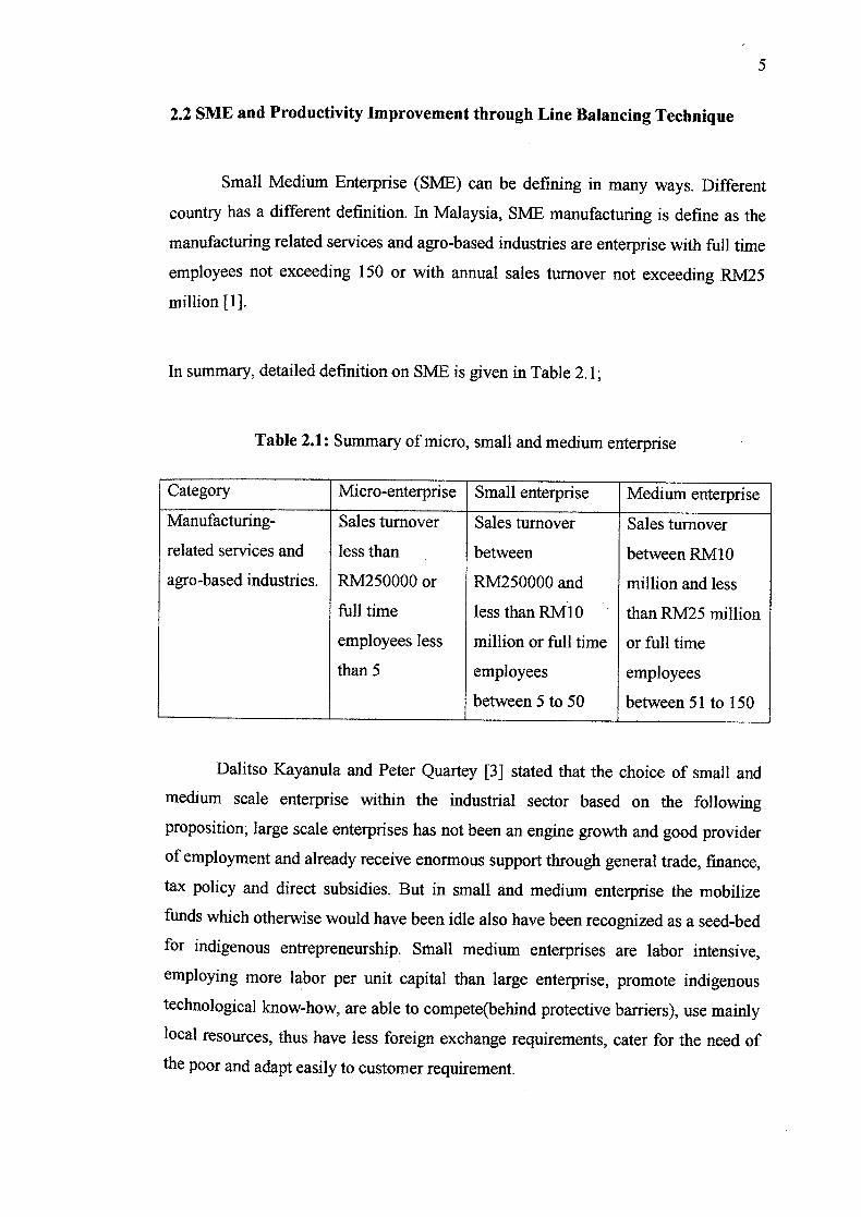
2.2 SME and Productivity Improvement through Line Balancing Technique
Small Medium Enterprise (SME) can be defining in many ways. Different
country has a different definition. In Malaysia, SME manufacturing is define as the
manufacturing related services and agro-based industries are enterprise with full time
employees not exceeding 150 or with annual sales turnover not exceeding RM25
million {1}.
In summary, detailed definition on SME is given in Table 2.1;
Table 2.1: Summary of micro, small and medium enterprise
Category Micro-enterprise Small enterprise Medium enterprise
Manufacturing- Sales turnover Sales turnover Sales turnover
related services and less than between between RM1O
agro-based industries. RM250000 or RM250000 and million and less
full time less than RIvIlO than RM25 million
employees less million or full time or full time
than 5 employees employees
between 5 to 50 between 51 to 150
Dalitso Kayanula and Peter Quartey [3] stated that the choice of small and
medium scale enterprise within the industrial sector based on the following
proposition; large scale enterprises has not been an engine growth and good provider
of employment and already receive enormous support through general trade, finance,
tax policy and direct subsidies. But in small and medium enterprise the mobilize
funds which otherwise would have been idle also have been recognized as a seed-bed
for indigenous entrepreneurship. Small medium enterprises are labor intensive,
employing more labor per unit capital than large enterprise, promote indigenous
technological know-how, are able to compete(behind protective barriers), use mainly
local resources, thus have less foreign exchange requirements, cater for the need of
the poor and adapt easily to customer requirement.
on
Small medium enterprise also faced the problem in managing the
arrangement of the assembly line. This is because lack of knowledge in management
to get the maximum production by using minimum man power.
Since SME play a significant role in national economy, there need to help
them to improve their competitiveness. Most of SME operate with poor forecasting
and planning systems and long cycle times. These result in poor delivery
performance and high inventories. Harold T.Amrine [4] suggested that to overcomes
these problems, it is important to SUE to implant the material management systems
based on material requirement planning or just in time concept (JIT)fKanban or line
balancing technique. Many of companies are under constant pressure to maintain
high production standard and efficient production process and control system.
In the large company such as Daimler Chrysler or Chevrolet, the assembly
line must correct and balanced [7]. The fabrication and assembly line must be
balanced. That is, the time spent to perform work on one machine must equal or
balance to the time spent on the next machine in the fabrication line, just as the time
spent at one workstation by one assembly line employee must balance the time spent
at the next workstation by next employee.
In the company, the management goal is to create a smooth, continuous flow
along the assembly line with a minimum of idle time at each workstation. A well
balanced assembly line has advantage of high personnel and facility utilization and
equity among employees work load. Some union contracts required that Work loads
be nearly equal among those on assembly line.
To know the effectiveness of the assembly line there has a two ways that is
by using manual arrangement and using the simulation combine with manual
calculation. In using manual arrangement, the layout must be create on the spot mean
that the arrangement must be doing in that layout and take the result in the final
output. By using simulation, the layout just be made in the software and the best
layout will be choosing without doing the arrangement first.
7
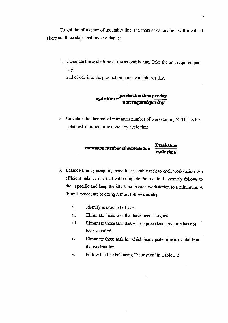
To get the efficiency of assembly line, the manual calculation will involved.
fhere are three steps that involve that is:
1. Calculate the cycle time of the assembly line. Take the unit required per
day
and divide into the production time available per day.
- production timeper day cyden -
unit required per day
2. Calculate the theoretical minimum number of workstation, N. This is the
total task duration time divide by cycle time.
minimum tatlon--cydethne
3. Balance line by assigning specific assembly task to each workstation. An
efficient balance one that will complete the required assembly follows to
the specific and keep the idle time in each workstation to a minimum. A
formal procedure to doing it must follow this step:
i. Identify master list of task.
ii. Eliminate those task that have been assigned
iii. Eliminate those task that whose precedence relation has not
been satisfied
iv. Eliminate those task for which inadequate time is available at
the workstation
V. Follow the line balancing "heuristics" in Table 2.2

8
Table 2.2: Line Balancing heuristic
T longest task time Choose the available task with the longest task time
most following task Choose the available task with the largest number of
following tasks
ranked position weight Choose the available task for which the sum of
following task time is the longest
shortest task time Choose the available task with the shortest task time
least number of
following task
Choose the available task with the least number of
following task
2.3 Verification using simulation technique
A simulation is an imitation of some real thing, state of affairs or process.
The act of simulation something generally entails representing certain key of
characteristic or behaviors of a selected physical or abstract system [8]. Simulation
also is the attempt to duplicate the features, appearance and characteristic of a real
system. The idea behind simulation is threefold that is [7]:
i. To imitate a real world situation mathematically,
ii. Then to study its properties and operating characteristic
Finally to draw conclusion and make the action based on the result from
simulation.
There are many advantages by using the simulation such as to analyze the
utilization or fixed resource and variable resources, do the testing to model without
damage or disturb the original model, to estimate the operating characteristic or
objective function value and analyze the problem.
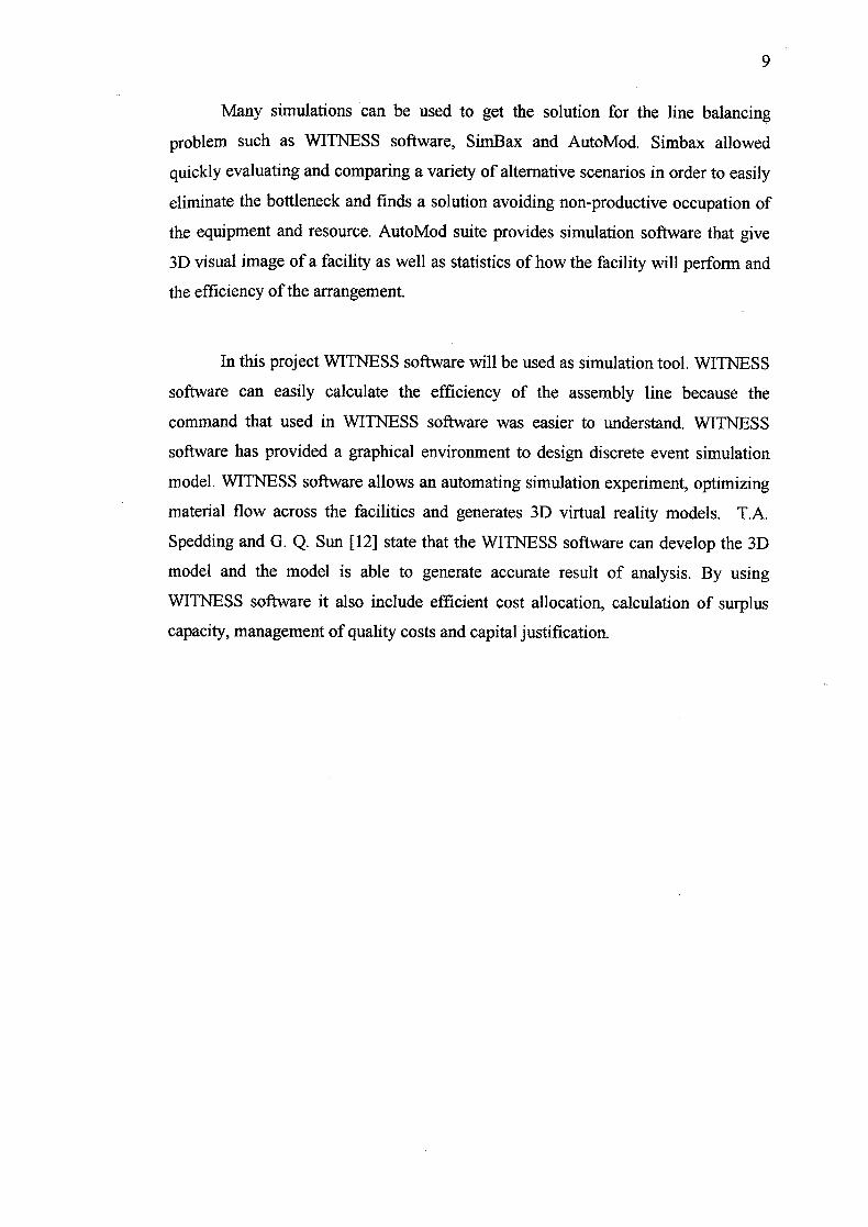
Many simulations can be used to get the solution for the line balancing
problem such as WITNESS software, SimBax and AutoMod. Simbax allowed
quickly evaluating and comparing a variety of alternative scenarios in order to easily
eliminate the bottleneck and finds a solution avoiding non-productive occupation of
the equipment and resource. AutoMod suite provides simulation software that give
3D visual image of a facility as well as statistics of how the facility will perform and
the efficiency of the arrangement.
In this project WITNESS software will be used as simulation tool. WITNESS
software can easily calculate the efficiency of the assembly line because the
command that used in WITNESS software was easier to understand. WITNESS
software has provided a graphical environment to design discrete event simulation
model. WITNESS software allows an automating simulation experiment, optimizing
material flow across the facilities and generates 3D virtual reality models. T.A.
Spedding and G. Q. Sun [12] state that the WITNESS software can develop the 3D
model and the model is able to generate accurate result of analysis. By using
WITNESS software it also include efficient cost allocation, calculation of surplus
capacity, management of quality costs and capital justification.
CHAPTER 3
METHODOLOGY
3.1 Introduction
In order to achieve the objectives and goal of the project, the methodology
flow chart has been planned and designed. The main objective to do the methodology
flow chart is to be a guideline and direction to make sure the project run smoothly
and successfully. In this project many of method will be used such as calculate the
cycle time, define the material handling, define the bill of material and calculate the
total time. Because a lot of calculation involve in this project, the simulation will be
used to make sure the result easier to get and will produce faster. WITNESS software
is the software that will be used as a simulation tool.
I
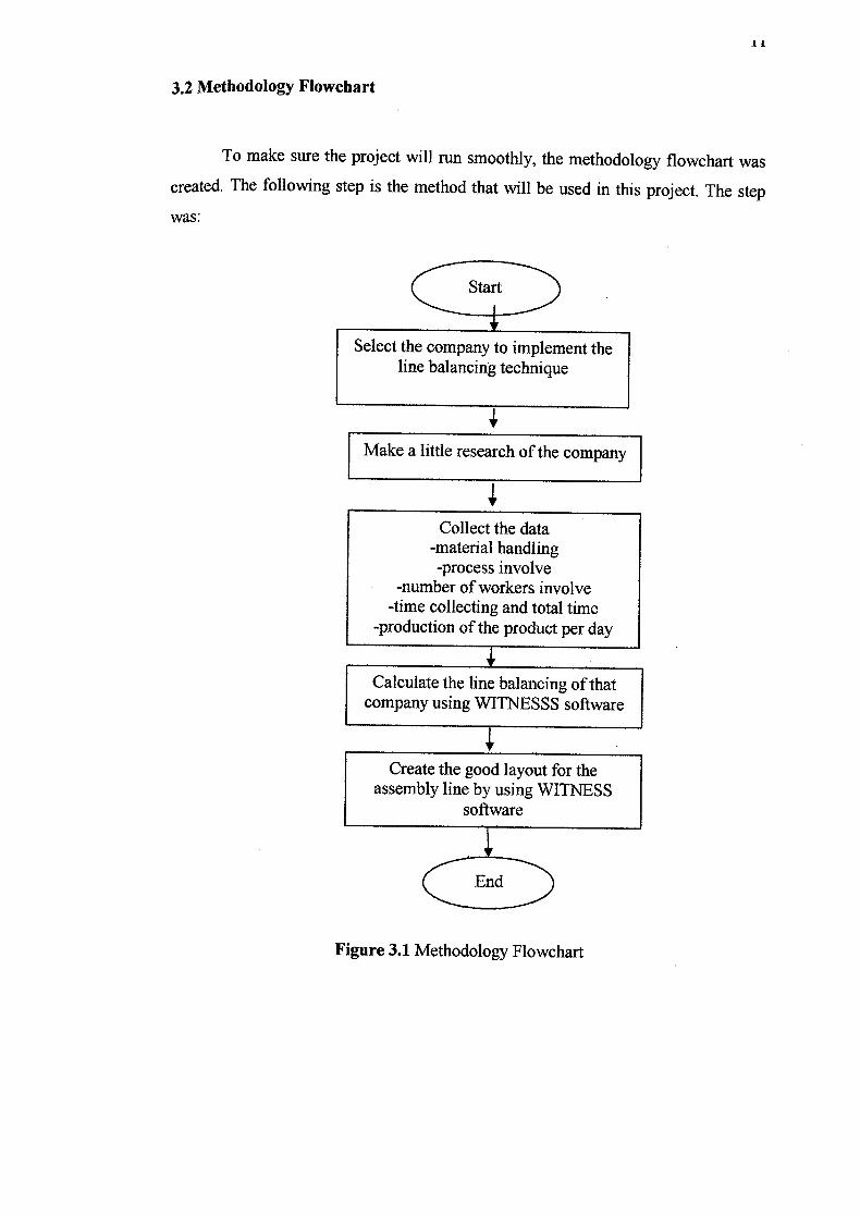
3.2 Methodology Flowchart
To make sure the project will run smoothly, the methodology flowchart was
created. The following step is the method that will be used in this project. The step
was:
Start
Select the company to implement the line balancing technique
Make a little research of the company
Collect the data -material handling -process involve
-number of workers involve -time collecting and total time
-production of the product per day
Calculate the line balancing of that company using WITNESSS software
Create the good layout for the assembly line by using WITNESS
software
End
Figure 3.1 Methodology Flowchart

12
3.2.1 Company choosing
Make a little research of the production rate of the company and the process
that involve to make a product because in the company that has many assembly line
so that this research is to make sure that the choosing of the assembly line is correct
place and correct time to apply the line balancing technique.
3.2.2 Data collection
A material handling system of the assembly line will be identified to know
the process involve in the assembly line. Material handling system is the
management of the movement in the organization. The function of material handling
system is to move the right material to the right place at the right time in the right
amount in sequence and in the right position or condition to minimize the production
cost. Number of workers also must being identified to know where the place or
machine that needed the worker. Total time and time collecting also will be observed
and recorded. Total time is the amount of time that the assembly line finishes all task
work in all workstation to make one product. Time collecting is the amount of time
used to complete the task by one workstation. The step to collect the data was:
i. Define the number of workstation (coded).
ii. Identify the process that involve in that assembly line.
iii. Identify the detail of activities in each workstation.
iv. Recorded the travel time that is the amount of time that the products pass
from one workstation to another workstation.
V. Recorded the setup time. Setup time is the time that the workers prepare the
thing before assembly it.
vi. Recorded the observed time that is the amount of time that the worker or the
machine to do the assembly.
13
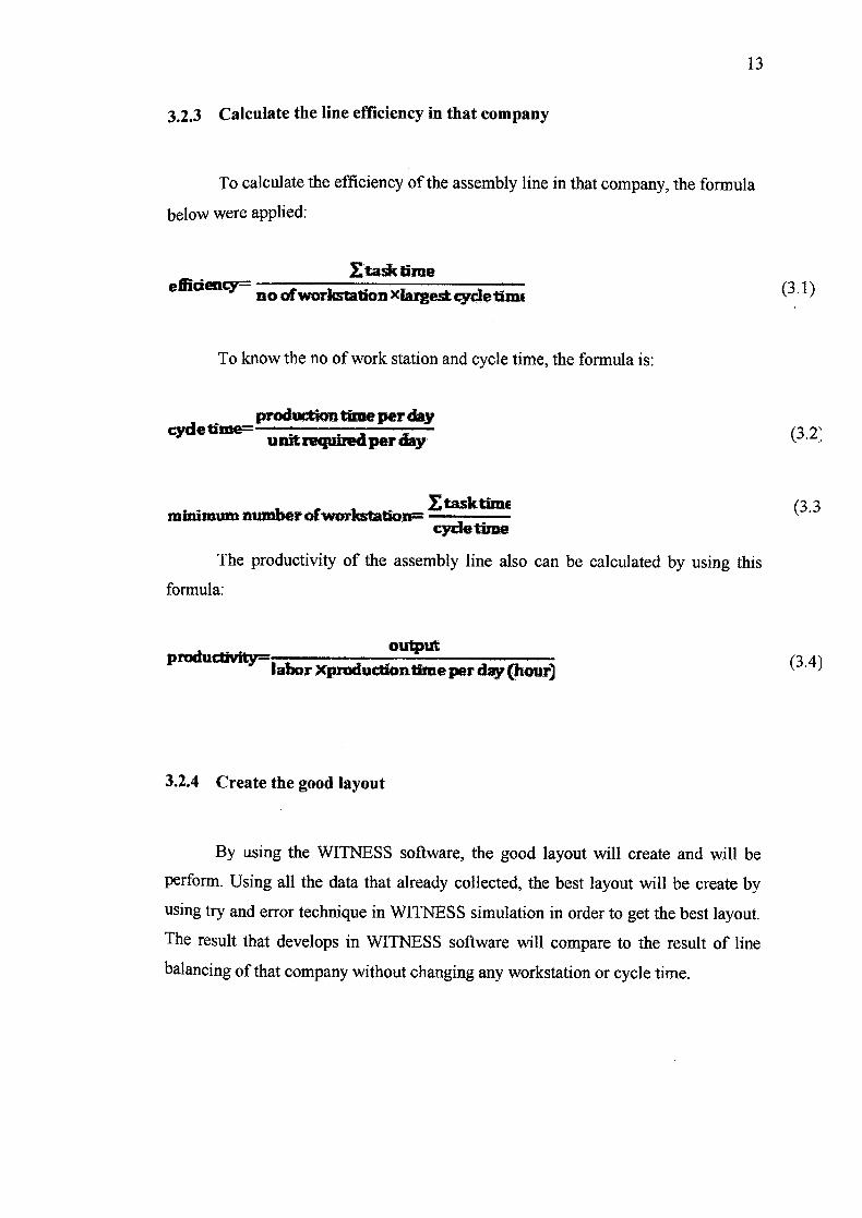
3.2.3 Calculate the line efficiency in that company
To calculate the efficiency of the assembly line in that company, the formula
below were applied:
£taktime efi1deflcY=0 of workstation Xiargest cycle thnc
To know the no of work station and cycle time, the formula is:
produdion time per day cyde ti me unit required per day
- minimum number ofwcrkstatlon= EtasktimE
Ce time
The productivity of the assembly line also can be calculated by using this
formula:
output - odUvlt — 1
Xpmducthntirne per day (hour)
3.2.4 Create the good layout
By using the WITNESS software, the good layout will create and will be
perform. Using all the data that already collected, the best layout will be create by
using try and error technique in WITNESS simulation in order to get the best layout.
The result that develops in WITNESS software will compare to the result of line
balancing of that company without changing any workstation or cycle time.
(3.1)
(3.2:
(3.3
(3.4J
14
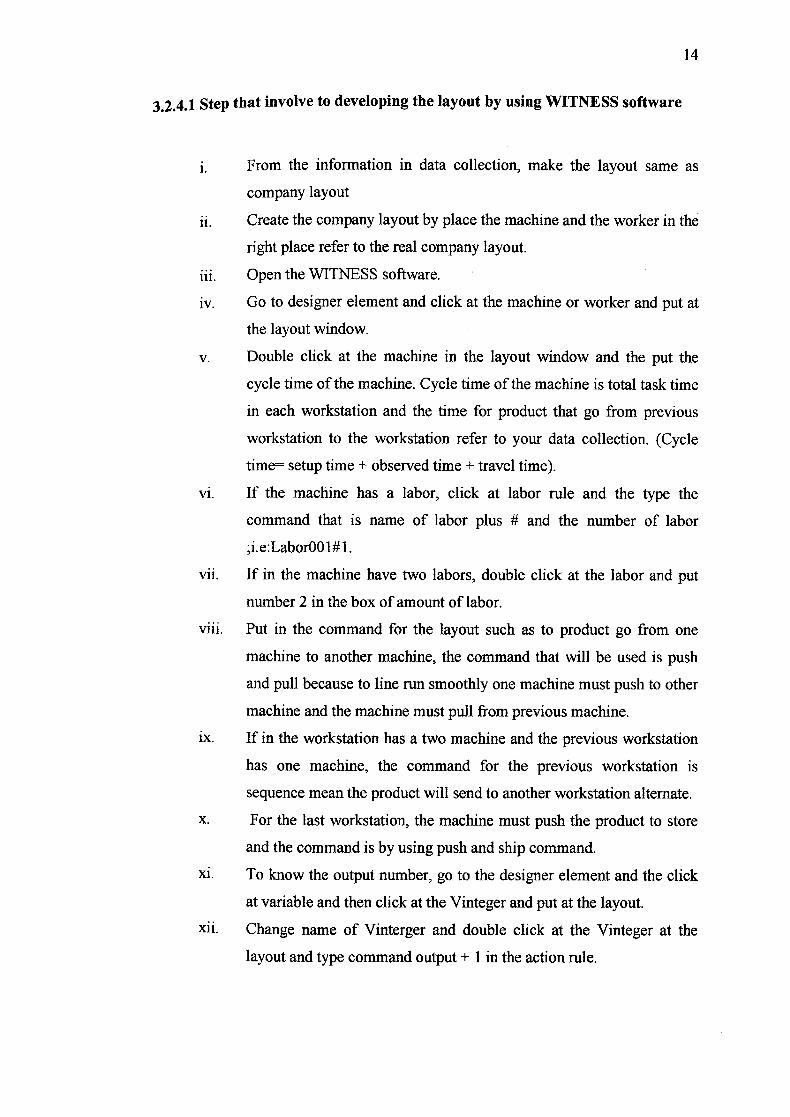
3.2.4.1 Step that involve to developing the layout by using WITNESS software
j. From the information in data collection, make the layout same as
company layout
i. Create the company layout by place the machine and the worker in the
right place refer to the real company layout.
Open the WITNESS software.
iv. Go to designer element and click at the machine or worker and put at
the layout window.
V. Double click at the machine in the layout window and the put the
cycle time of the machine. Cycle time of the machine is total task time
in each workstation and the time for product that go from previous
workstation to the workstation refer to your data collection. (Cycle
time= setup time + observed time + travel time).
vi. If the machine has a labor, click at labor rule and the type the
command that is name of labor plus # and the number of labor
;i.e:LaborOOl#l.
vii. If in the machine have two labors, double click at the labor and put
number 2 in the box of amount of labor.
viii. Put in the command for the layout such as to product go from one
machine to another machine, the command that will be used is push
and pull because to line run smoothly one machine must push to other
machine and the machine must pull from previous machine.
ix. If in the workstation has a two machine and the previous workstation
has one machine, the command for the previous workstation is
sequence mean the product will send to another workstation alternate.
X. For the last workstation, the machine must push the product to store
and the command is by using push and ship command.
xi. To know the output number, go to the designer element and the click
at variable and then click at the Vinteger and put at the layout.
xii. Change name of Vinterger and double click at the Vinteger at the
layout and type command output + 1 in the action rule.