Embed Size (px)
Citation preview
Professional HD Integrated Receiver Decoder
GEOSATpro DSR160SDI
User Manual
V1.00-C
1
Preface About This Manual This manual provides introductions to users about how to operate the device correctly. The
content includes introduction to product installation, product characteristics and product
settings, etc.
It is highly suggested users to go through this document before actually operating the
device.
Intended Readers This manual is suggested to be studied by the following readers:
l Technical Service Engineer
l Maintenance Engineer
l Test Engineer
l Sales Engineer
Symbols Definition For the symbols that might appear in this document, the meanings they represent are as the
following:
Symbol Meaning
There is highly potential danger. If it cannot be avoided, it will lead to the deaths or
serious injury.
There is medium or low potential danger. If it cannot be avoided, it will lead to medium
or slight injury.
There are potential risks. If ignore these texts, it may cause damage to the device,
data loss, equipment performance reduce or unpredictable results.
2
Tips that help you to solve problems or save your time.
Remarks. Additional information to the text, in order to emphasize something.
Revision History The revision history lists the modification history. The newest one contains all the
modifications of the past revision.
l V1.00-C: First revision of the manual. (Date: March 26th, 2015)
3
Contents 1 About This Product ......................................................................................................... 4
1.1Introduction ............................................................................................................... 41.2 Safety ....................................................................................................................... 41.3 Architecture .............................................................................................................. 51.4 Methods of Operation ............................................................................................... 6
1.4.1 Operation through WEB UI ............................................................................ 61.4.2Operation through Front Panel Operation ...................................................... 7
1.5 Technical Specifications ........................................................................................... 71.5.1 Physical Specifications .................................................................................. 71.5.2 Performance and Capacity ............................................................................ 81.5.3 Interfaces and Protocols ................................................................................ 8
2 Installation ...................................................................................................................... 92.1 Installation Procedure .............................................................................................. 92.2 Preparation before Installation ................................................................................. 92.3 Check Package and Accessories ........................................................................... 102.4 Equipment Wiring and Connection ......................................................................... 10
2.4.1 Connection Setup for RF Signal Input ......................................................... 112.4.2 Connection Setup for ASI signal input ........... Error! Bookmark not defined.
3 Operation Guide ........................................................................................................... 123.1.Operation Overview ............................................................................................... 123.2.Powering Up and Initialization ............................................................................... 123.3.Front Panel Operation ........................................................................................... 12
3.3.1Front Panel Menu Structure ......................................................................... 133.3.2Front Panel Operation Guide ....................................................................... 16
3.4. WEB UI Operation (Recommended) ................................................................ 163.4.1WEB Management Connecting .................................................................... 173.4.2Parameters Configuration ............................................................................ 18
3.5. Operation Verification ......................................... Error! Bookmark not defined.3.5.1Signal Reception Verification ......................... Error! Bookmark not defined.3.5.2Descrambling Function Verification ................ Error! Bookmark not defined.3.5.3Decoding Function Verification ....................... Error! Bookmark not defined.
3.6. Preparation before Officially Operation .............. Error! Bookmark not defined.3.6.1Clear all useless data ..................................... Error! Bookmark not defined.3.6.2Configure the equipment with working data ... Error! Bookmark not defined.3.6.3Full checking before implementation .............. Error! Bookmark not defined.
4 FAQ ................................................................................ Error! Bookmark not defined.5 Terminology .................................................................... Error! Bookmark not defined.
4
1 About This Product 1.1 Introduction This product is a new generation integrated receiver decoder to support the growing
demands for multi-format, multi-standard video delivery and distribution. It can receive
digital signals from DVB-S/S2, decrypt, and process/select programs to various outputs
including CVBS, Component, HDMI, and SDI. It supports multi-channel descrambling,
multiplexing, external table/data insertion. It also supports video decoding with two audio
channels. With remote web-based management interface, it is ideal to support advanced
application such as content distribution, real-time signal conversion and transmission.
1.2 Safety
l To avoid electric-shock hazards, do not open the receiver; refer service to qualified
personnel only.
l Do not expose the device in the sunlight, and keep it away from the heat source.
l Do not block ventilation holes of the device so that air can circulate freely.
l Switch the device off whenever it remains out of service for an extended period.
l Be sure to turn the device off and disconnect the AC power cord before cleaning the
receiver surface.
l The apparatus shall be connected the mains socket outlet with a protective earthing
connection
l The appliance coupler used as the disconnect device shall remain readily operable.
l This product has gone through regulated EMC test and meets with EMC safety
requirement.
( Such tests are conducted in a controlled EMC environment. A controlled
EMC environment exists in a building where the installation has been designed having special regards to EMC, and where technical personnel are present with experience of EMC technology.)
5
1.3 Architecture The equipment of this section is shown in schematic diagram. It is subject
to change for improvement on the real product without advanced notice.
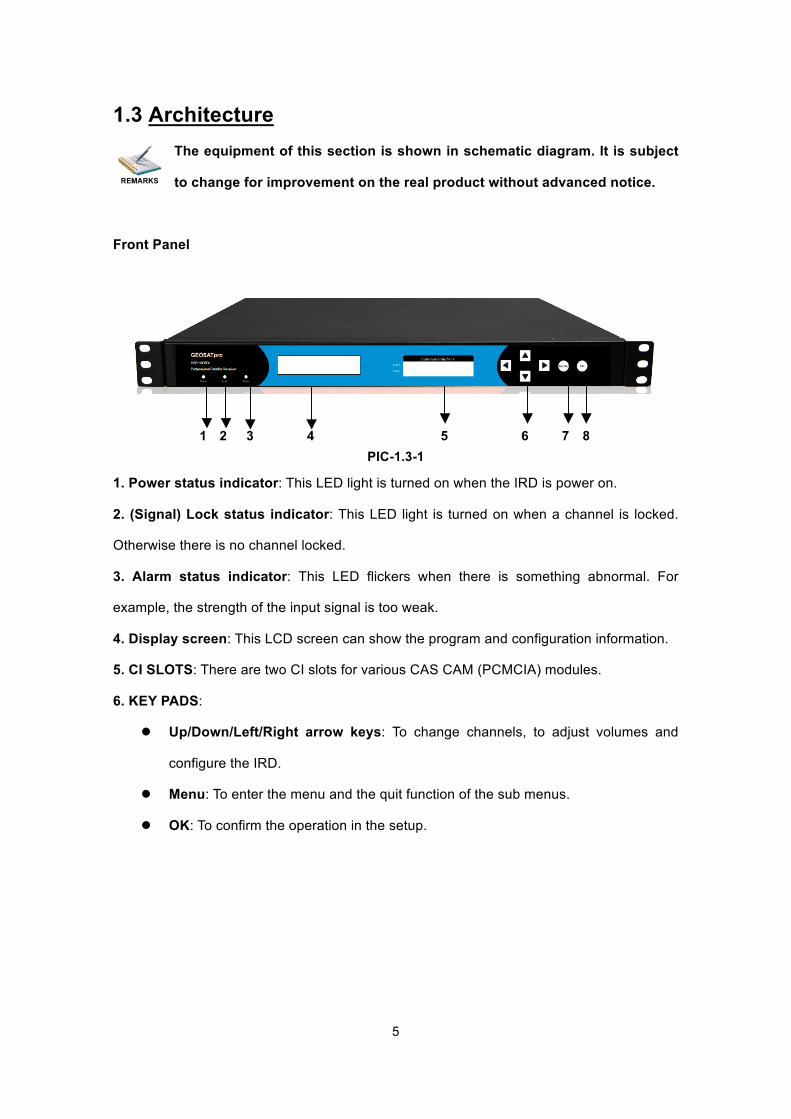
Front Panel
1 2 3 4 5 6 7 8
PIC-1.3-1
1. Power status indicator: This LED light is turned on when the IRD is power on.
2. (Signal) Lock status indicator: This LED light is turned on when a channel is locked.
Otherwise there is no channel locked.
3. Alarm status indicator: This LED flickers when there is something abnormal. For
example, the strength of the input signal is too weak.
4. Display screen: This LCD screen can show the program and configuration information.
5. CI SLOTS: There are two CI slots for various CAS CAM (PCMCIA) modules.
6. KEY PADS:
l Up/Down/Left/Right arrow keys: To change channels, to adjust volumes and
configure the IRD.
l Menu: To enter the menu and the quit function of the sub menus.
l OK: To confirm the operation in the setup.
6
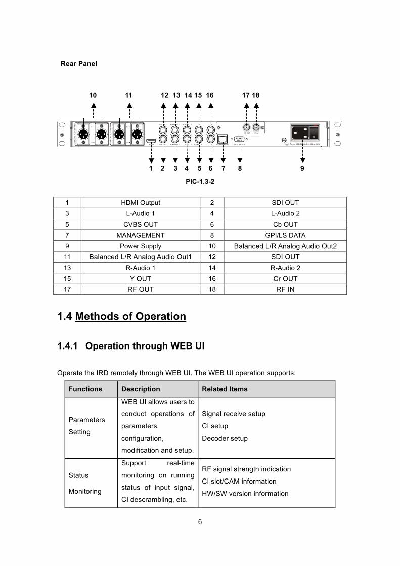
Rear Panel
10 11 12 .13 .14 15 .16 17 18
1 . .2 .3 4 .5 6 .7 .8 .9
PIC-1.3-2
1 HDMI Output 2 SDI OUT 3 L-Audio 1 4 L-Audio 2 5 CVBS OUT 6 Cb OUT 7 MANAGEMENT 8 GPI/LS DATA 9 Power Supply 10 Balanced L/R Analog Audio Out2 11 Balanced L/R Analog Audio Out1 12 SDI OUT 13 R-Audio 1 14 R-Audio 2 15 Y OUT 16 Cr OUT 17 RF OUT 18 RF IN
1.4 Methods of Operation
1.4.1 Operation through WEB UI
Operate the IRD remotely through WEB UI. The WEB UI operation supports:
Functions Description Related Items
Parameters
Setting
WEB UI allows users to
conduct operations of
parameters
configuration,
modification and setup.
Signal receive setup
CI setup
Decoder setup
Status
Monitoring
Support real-time
monitoring on running
status of input signal,
CI descrambling, etc.
RF signal strength indication
CI slot/CAM information
HW/SW version information
7
Functions Description Related Items
Upgrade Support unit upgrade
through WEB UI
1.4.2 Operation through Front Panel Operation
Operation through front panel control buttons; users can configure all the parameters as the
followings:
Functions Description Related Items
Parameters
Setting
Allows users to
conduct operations of
parameters
configuration,
modification and setup.
Signal receive setup
CI setup
Decoder setup
Status
Monitoring
Support real-time
monitoring on running
status of input signal,
CI descrambling, etc.
RF signal strength indication
CI slot/CAM information
HW/SW version information
1.5 Technical Specifications
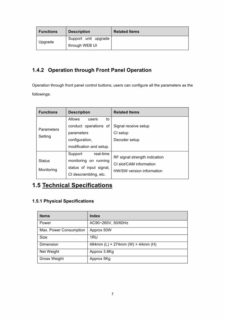
1.5.1 Physical Specifications
Items Index Power AC90~260V, 50/60Hz
Max. Power Consumption Approx 50W
Size 1RU
Dimension 484mm (L) × 274mm (W) × 44mm (H)
Net Weight Approx 3.8Kg
Gross Weight Approx 5Kg
8
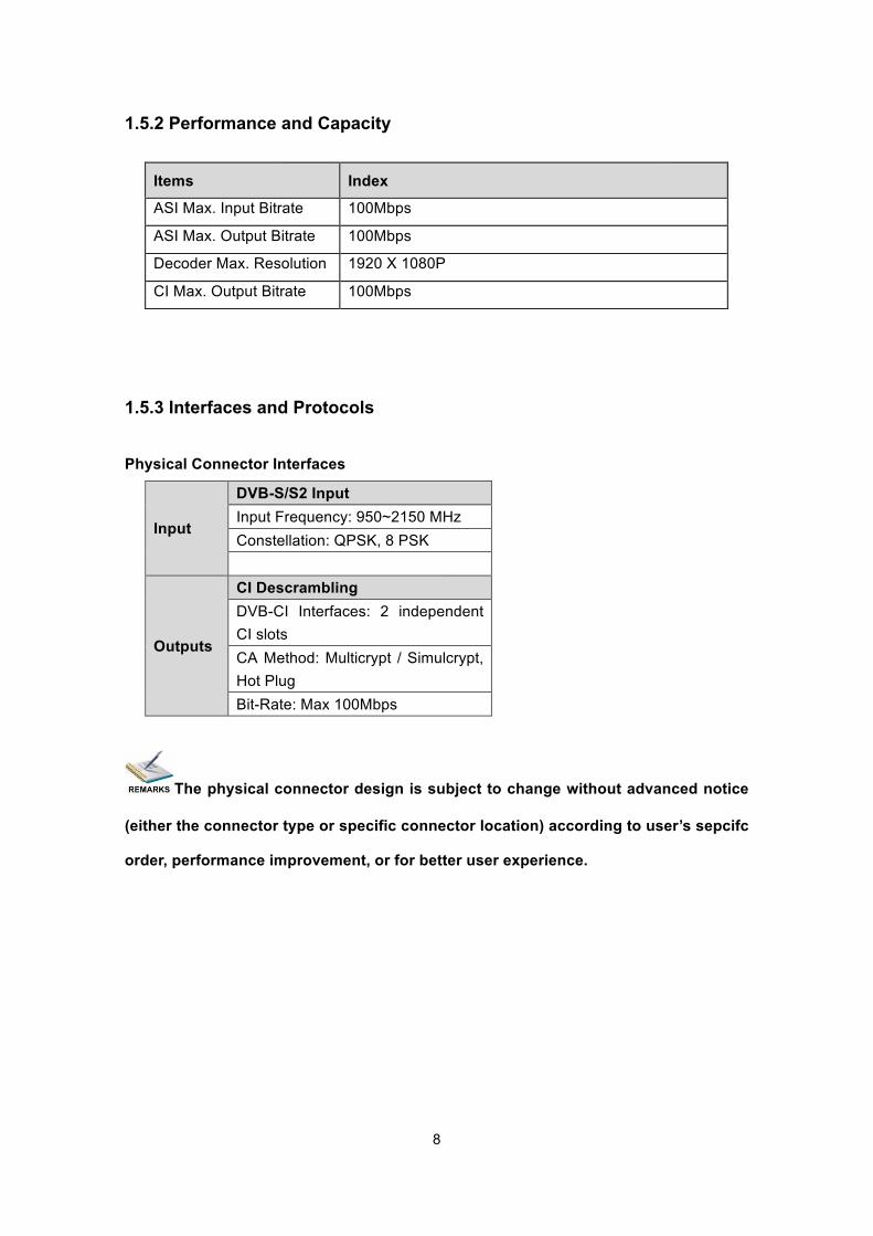
1.5.2 Performance and Capacity
Items Index
ASI Max. Input Bitrate 100Mbps
ASI Max. Output Bitrate 100Mbps
Decoder Max. Resolution 1920 X 1080P
CI Max. Output Bitrate 100Mbps
1.5.3 Interfaces and Protocols
Physical Connector Interfaces
Input
DVB-S/S2 Input Input Frequency: 950~2150 MHz Constellation: QPSK, 8 PSK
Outputs
CI Descrambling DVB-CI Interfaces: 2 independent CI slots CA Method: Multicrypt / Simulcrypt, Hot Plug Bit-Rate: Max 100Mbps
The physical connector design is subject to change without advanced notice
(either the connector type or specific connector location) according to user’s sepcifc
order, performance improvement, or for better user experience.
9
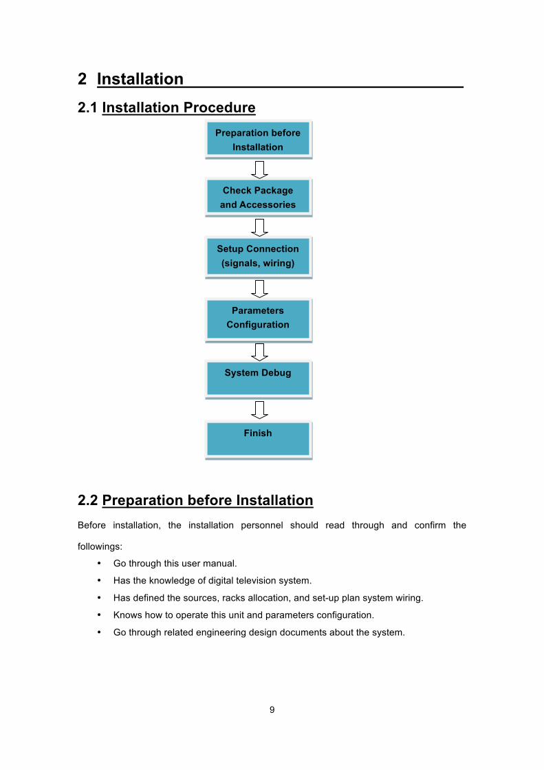
2 Installation 2.1 Installation Procedure
2.2 Preparation before Installation Before installation, the installation personnel should read through and confirm the
followings:
• Go through this user manual.
• Has the knowledge of digital television system.
• Has defined the sources, racks allocation, and set-up plan system wiring.
• Knows how to operate this unit and parameters configuration.
• Go through related engineering design documents about the system.
Preparation before Installation
Check Package and Accessories
Setup Connection (signals, wiring)
Parameters Configuration
System Debug
Finish
10
2.3 Check Package and Accessories The IRD package includes the following accessories:
l Base Unit x1
l Power cord x1
l Earth cord x1
l BNC cord x2
l BNC-RCA cord x3
l User Manuel Disc x1
l Quick Installation Guide x1
2.4 Equipment Wiring and Connection
To avoid electric shock and damage to the equipment, before setting up the wiring connection, please power off the equipment and all other connected external devices. The equipment and external devices must be grounded. Powering on the equipment only after all the wiring connection is completed.
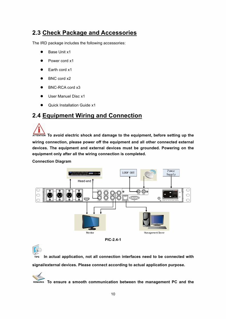
Connection Diagram
PIC-2.4-1
In actual application, not all connection interfaces need to be connected with
signal/external devices. Please connect according to actual application purpose.
To ensure a smooth communication between the management PC and the

11
IRD, please try to connect the IRD management port to a switch without large data processing.
2.4.1 Connection Setup for RF Signal Input
l Connect signal to tuner input with a RF cable.
l Connect the IRD “Management” port to a switch, set up a management network with the
management PC.
l Connect the IRD with the monitor via HDMI, SDI, component, or CVBS ports.
12
3 Operation Guide
3.1. Operation Overview
This chapter provides information on how to operate the IRD through front panel and WEB
UI. User can select the most proper operation method to set up the unit.
3.2. Powering Up and Initialization
Before powering-up the device, make sure that all cabling is correctly
connected (refer to chapter 3.4 of this manual). The device is correctly connected to the power inlet and grounded.
Switch on the equipment through the rear power switch, and the unit is powered up and
starts the initialization.
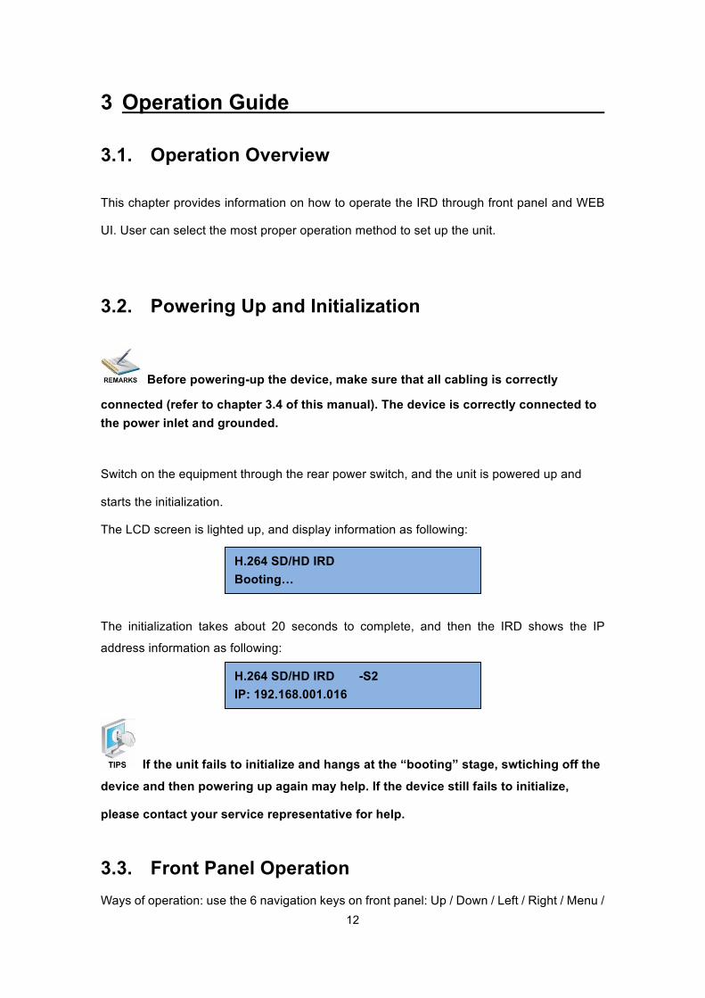
The LCD screen is lighted up, and display information as following:
The initialization takes about 20 seconds to complete, and then the IRD shows the IP
address information as following:
If the unit fails to initialize and hangs at the “booting” stage, swtiching off the
device and then powering up again may help. If the device still fails to initialize,
please contact your service representative for help.
3.3. Front Panel Operation Ways of operation: use the 6 navigation keys on front panel: Up / Down / Left / Right / Menu /
H.264 SD/HD IRD -S2 IP: 192.168.001.016
H.264 SD/HD IRD Booting…
13
Ok to configure the IRD parameters. The configuration and settings are displayed through
front panel LCD.
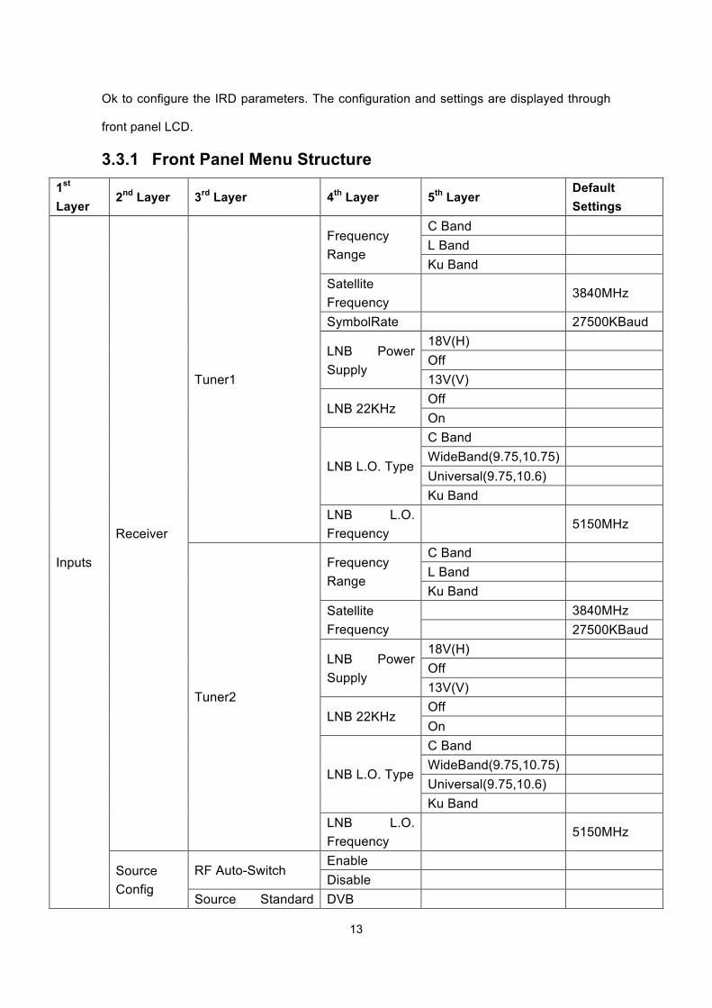
3.3.1 Front Panel Menu Structure 1st Layer
2nd Layer 3rd Layer 4th Layer 5th Layer Default Settings
Inputs
Receiver
Tuner1
Frequency Range
C Band L Band Ku Band
Satellite Frequency
3840MHz
SymbolRate 27500KBaud
LNB Power Supply
18V(H) Off 13V(V)
LNB 22KHz Off On
LNB L.O. Type
C Band WideBand(9.75,10.75) Universal(9.75,10.6) Ku Band
LNB L.O. Frequency
5150MHz
Tuner2
Frequency Range
C Band L Band Ku Band
Satellite Frequency
3840MHz 27500KBaud
LNB Power Supply
18V(H) Off 13V(V)
LNB 22KHz Off On
LNB L.O. Type
C Band WideBand(9.75,10.75) Universal(9.75,10.6) Ku Band
LNB L.O. Frequency
5150MHz
Source Config
RF Auto-Switch Enable Disable
Source Standard DVB
14
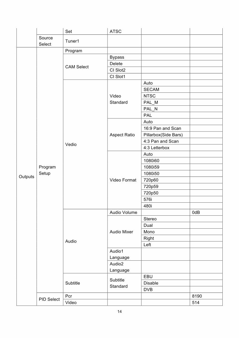
Set ATSC Source Select
Tuner1
Outputs
Program Setup
Program
CAM Select
Bypass Delete CI Slot2 CI Slot1
Vedio
Video Standard
Auto SECAM NTSC PAL_M PAL_N PAL
Aspect Ratio
Auto 16:9 Pan and Scan Pillarbox(Side Bars) 4:3 Pan and Scan 4:3 Letterbox
Video Format
Auto 1080i60 1080i59 1080i50 720p60 720p59 720p50 576i 480i
Audio
Audio Volume 0dB
Audio Mixer
Stereo Dual Mono Right Left
Audio1 Language
Audio2 Language
Subtitle Subtitle Standard
EBU Disable DVB
PID Select Pcr 8190 Video 514
15
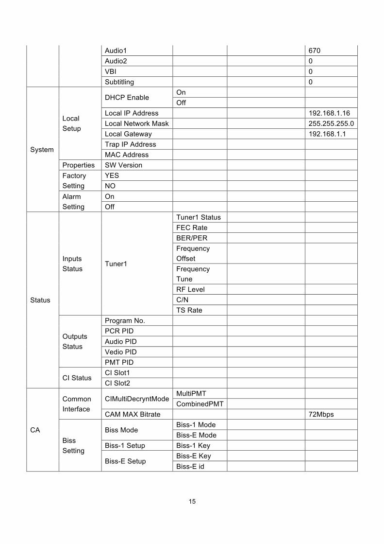
Audio1 670 Audio2 0 VBI 0 Subtitling 0
System
Local Setup
DHCP Enable On Off
Local IP Address 192.168.1.16 Local Network Mask 255.255.255.0 Local Gateway 192.168.1.1 Trap IP Address MAC Address
Properties SW Version Factory Setting
YES NO
Alarm Setting
On Off
Status
Inputs Status
Tuner1
Tuner1 Status FEC Rate BER/PER Frequency Offset
Frequency Tune
RF Level C/N TS Rate
Outputs Status
Program No. PCR PID Audio PID Vedio PID PMT PID
CI Status CI Slot1 CI Slot2
CA
Common Interface
CIMultiDecryntMode MultiPMT CombinedPMT
CAM MAX Bitrate 72Mbps
Biss Setting
Biss Mode Biss-1 Mode Biss-E Mode
Biss-1 Setup Biss-1 Key
Biss-E Setup Biss-E Key Biss-E id
16
3.3.2 Front Panel Operation Guide
• Enter “Menu”: o Press “MENU” button to enter main menu.
• Exit Menu/Back to parent Menu o Upon completion of configuration settings, press “MENU” button until you
go back to the Parent Menu.
• Enter Sub-Menu o Press MENU button to enter main menu.
o Select a sub-menu by pressing arrow UP and arrow DOWN button.
o Press OK button on the selected sub-menu.
• To change parameter o Step 1: Enter main menu by pressing MENU button.
o Step 2: Scroll sub-menu by pressing arrow UP and arrow DOWN button,
and press OK button to change the selected sub-menu.
o Step 3: To change parameter settings, press arrow RIGHT and arrow LEFT
button to move the cursor in which change must be made.
o Press arrow UP button and arrow DOWN to input / select an appropriate
setting, then press OK button to save.
3.4. WEB UI Operation (Recommended) Accessing the equipment via Web can be very convenient for remote configuration of the
equipment. Relative to the front panel settings WEB operation can provide a more friendly
man-machine interface, and with less limits in space. WEB Management is recommended.
17
3.4.1 WEB Management Connecting
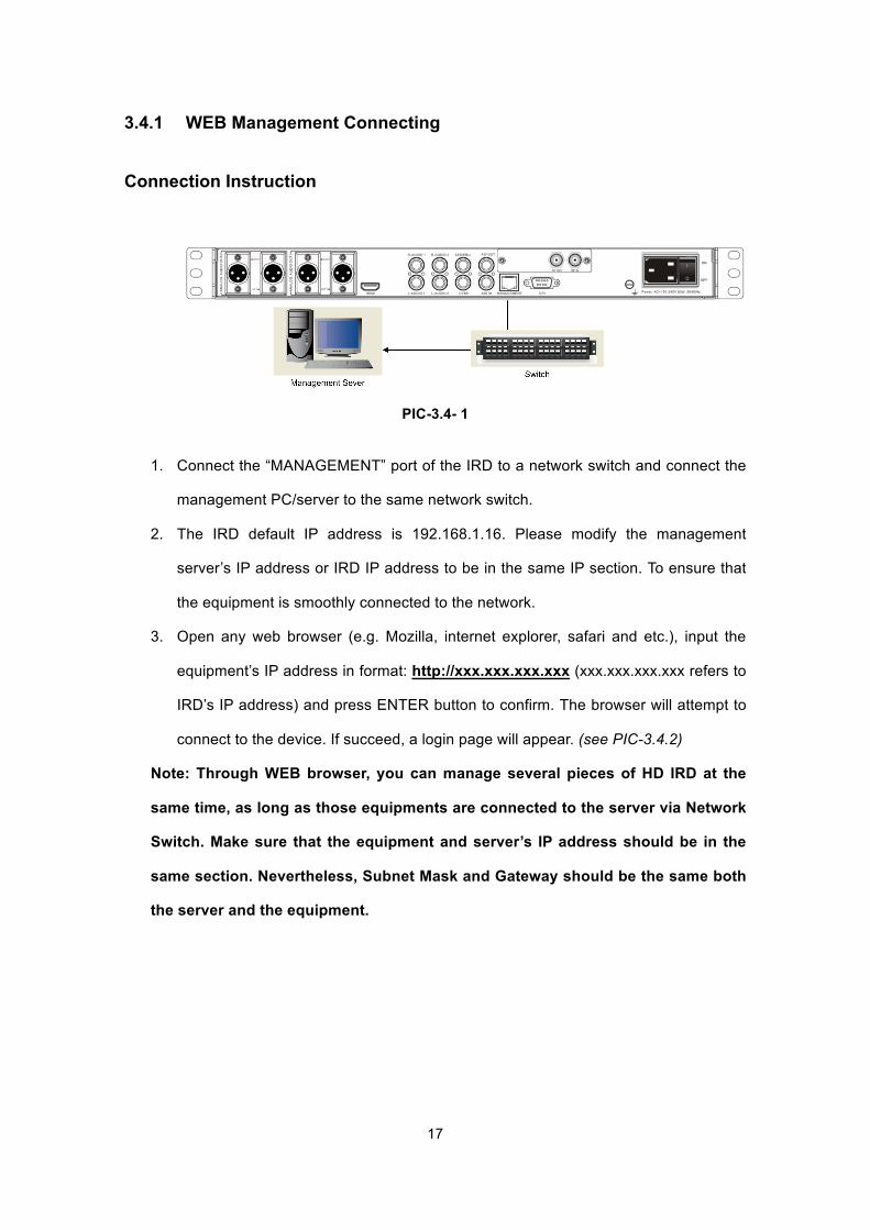
Connection Instruction
PIC-3.4- 1
1. Connect the “MANAGEMENT” port of the IRD to a network switch and connect the
management PC/server to the same network switch.
2. The IRD default IP address is 192.168.1.16. Please modify the management
server’s IP address or IRD IP address to be in the same IP section. To ensure that
the equipment is smoothly connected to the network.
3. Open any web browser (e.g. Mozilla, internet explorer, safari and etc.), input the
equipment’s IP address in format: http://xxx.xxx.xxx.xxx (xxx.xxx.xxx.xxx refers to
IRD’s IP address) and press ENTER button to confirm. The browser will attempt to
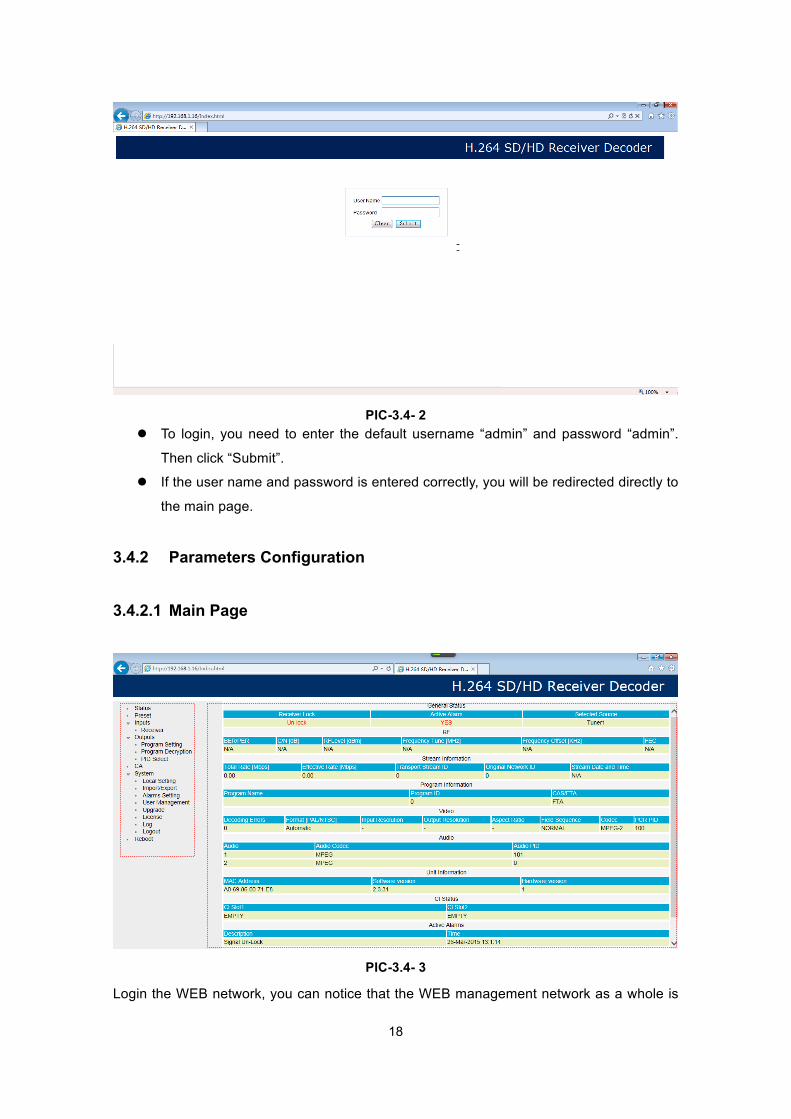
connect to the device. If succeed, a login page will appear. (see PIC-3.4.2)
Note: Through WEB browser, you can manage several pieces of HD IRD at the
same time, as long as those equipments are connected to the server via Network
Switch. Make sure that the equipment and server’s IP address should be in the
same section. Nevertheless, Subnet Mask and Gateway should be the same both
the server and the equipment.
18
PIC-3.4- 2 l To login, you need to enter the default username “admin” and password “admin”.
Then click “Submit”.
l If the user name and password is entered correctly, you will be redirected directly to
the main page.
3.4.2 Parameters Configuration
3.4.2.1 Main Page
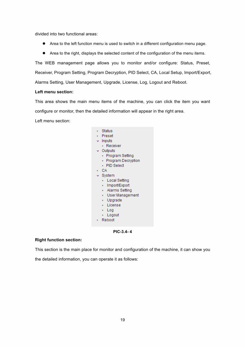
PIC-3.4- 3
Login the WEB network, you can notice that the WEB management network as a whole is
19
divided into two functional areas:
l Area to the left function menu is used to switch in a different configuration menu page.
l Area to the right, displays the selected content of the configuration of the menu items.
The WEB management page allows you to monitor and/or configure: Status, Preset,
Receiver, Program Setting, Program Decryption, PID Select, CA, Local Setup, Import/Export,
Alarms Setting, User Management, Upgrade, License, Log, Logout and Reboot.
Left menu section:
This area shows the main menu items of the machine, you can click the item you want
configure or monitor, then the detailed information will appear in the right area.
Left menu section:
PIC-3.4- 4
Right function section:
This section is the main place for monitor and configuration of the machine, it can show you
the detailed information, you can operate it as follows:
20
3.4.2.2 Status Page
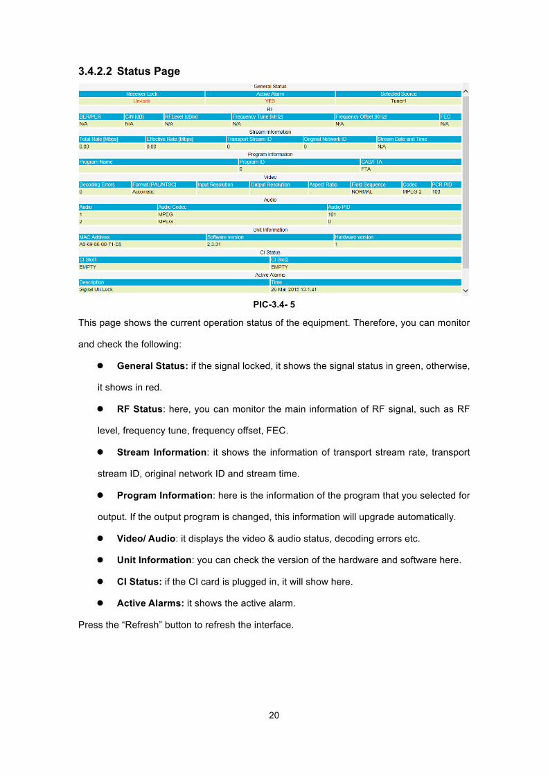
PIC-3.4- 5
This page shows the current operation status of the equipment. Therefore, you can monitor
and check the following:
l General Status: if the signal locked, it shows the signal status in green, otherwise,
it shows in red.
l RF Status: here, you can monitor the main information of RF signal, such as RF
level, frequency tune, frequency offset, FEC.
l Stream Information: it shows the information of transport stream rate, transport
stream ID, original network ID and stream time.
l Program Information: here is the information of the program that you selected for
output. If the output program is changed, this information will upgrade automatically.
l Video/ Audio: it displays the video & audio status, decoding errors etc.
l Unit Information: you can check the version of the hardware and software here.
l CI Status: if the CI card is plugged in, it will show here.
l Active Alarms: it shows the active alarm.
Press the “Refresh” button to refresh the interface.
21
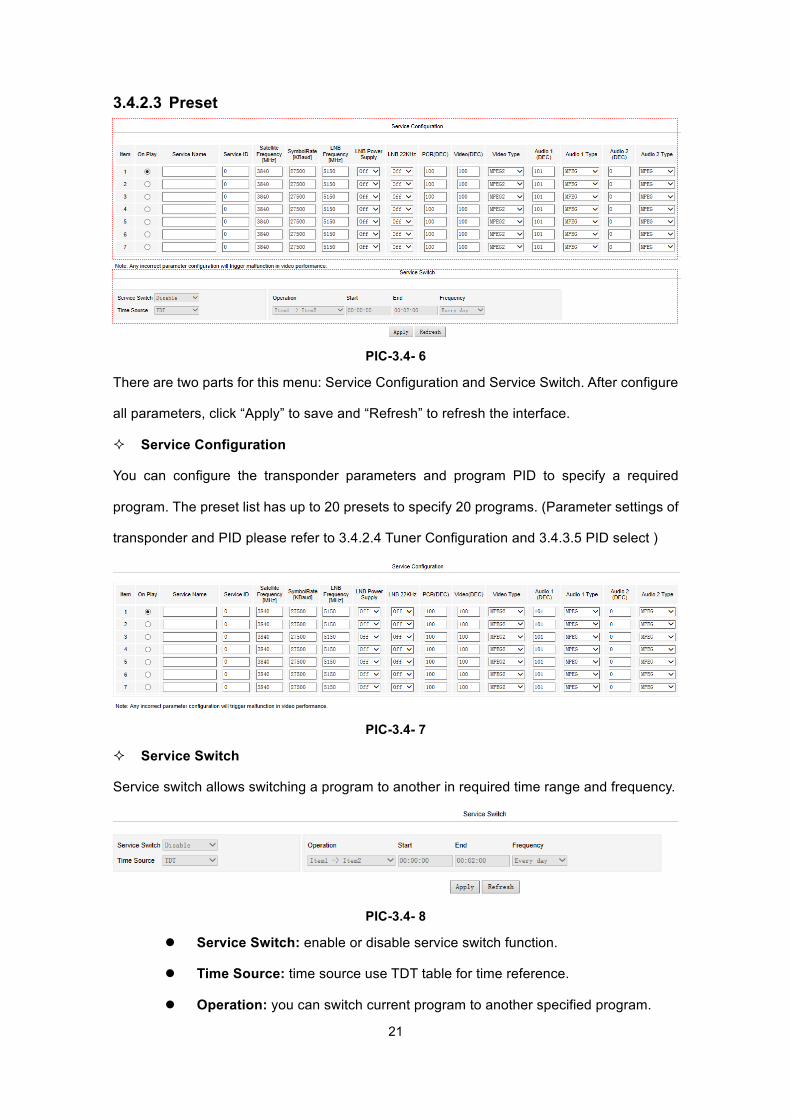
3.4.2.3 Preset
PIC-3.4- 6
There are two parts for this menu: Service Configuration and Service Switch. After configure
all parameters, click “Apply” to save and “Refresh” to refresh the interface.
² Service Configuration
You can configure the transponder parameters and program PID to specify a required
program. The preset list has up to 20 presets to specify 20 programs. (Parameter settings of
transponder and PID please refer to 3.4.2.4 Tuner Configuration and 3.4.3.5 PID select )
PIC-3.4- 7
² Service Switch
Service switch allows switching a program to another in required time range and frequency.
PIC-3.4- 8
l Service Switch: enable or disable service switch function.
l Time Source: time source use TDT table for time reference.
l Operation: you can switch current program to another specified program.
22
l Start: specify a time point to start switch.
l End: specify a time point to return to previous program.
l Frequency: choose the period to repeat the operation.
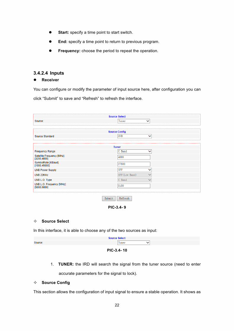
3.4.2.4 Inputs l Receiver
You can configure or modify the parameter of input source here, after configuration you can
click “Submit” to save and “Refresh” to refresh the interface.
PIC-3.4- 9
² Source Select
In this interface, it is able to choose any of the two sources as input:
PIC-3.4- 10
1. TUNER: the IRD will search the signal from the tuner source (need to enter
accurate parameters for the signal to lock).
² Source Config
This section allows the configuration of input signal to ensure a stable operation. It shows as
23
follows:
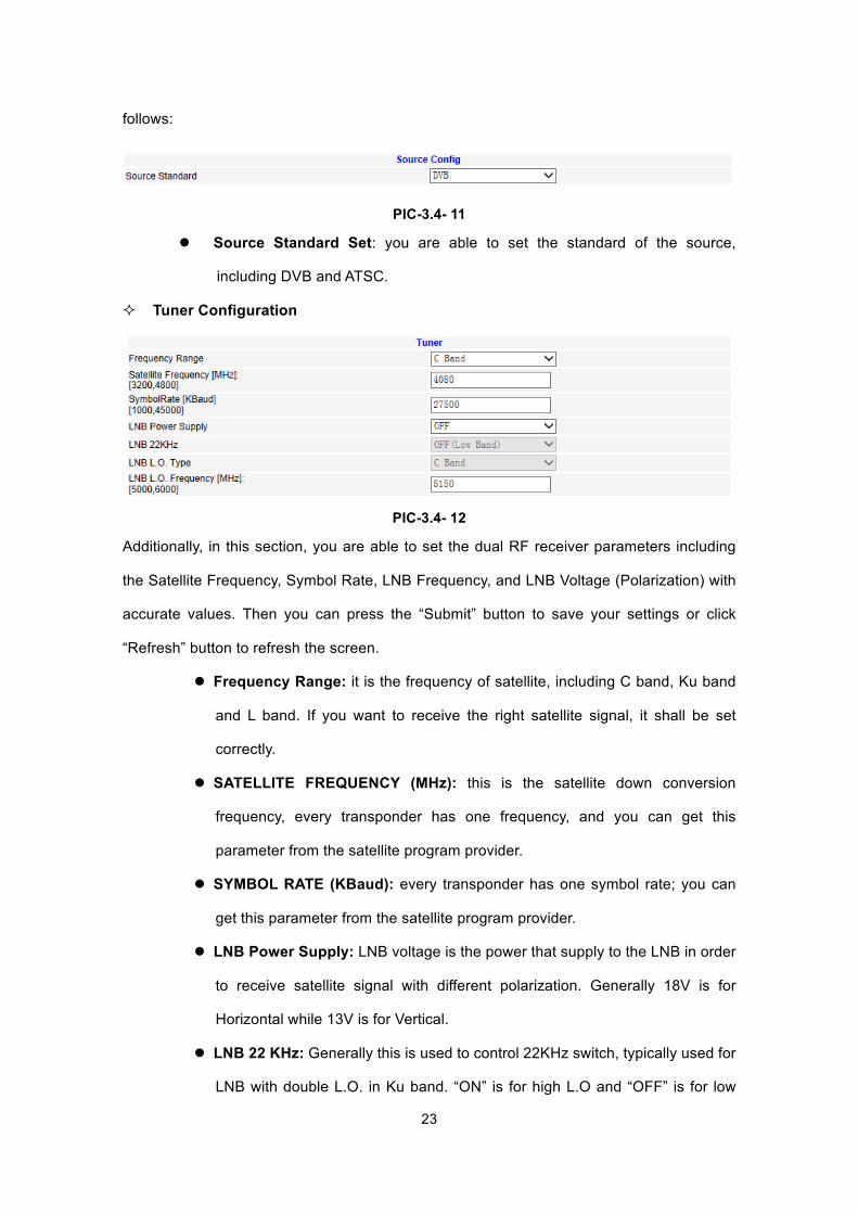
PIC-3.4- 11
l Source Standard Set: you are able to set the standard of the source,
including DVB and ATSC.
² Tuner Configuration
PIC-3.4- 12
Additionally, in this section, you are able to set the dual RF receiver parameters including
the Satellite Frequency, Symbol Rate, LNB Frequency, and LNB Voltage (Polarization) with
accurate values. Then you can press the “Submit” button to save your settings or click
“Refresh” button to refresh the screen.
l Frequency Range: it is the frequency of satellite, including C band, Ku band
and L band. If you want to receive the right satellite signal, it shall be set
correctly.
l SATELLITE FREQUENCY (MHz): this is the satellite down conversion
frequency, every transponder has one frequency, and you can get this
parameter from the satellite program provider.
l SYMBOL RATE (KBaud): every transponder has one symbol rate; you can
get this parameter from the satellite program provider.
l LNB Power Supply: LNB voltage is the power that supply to the LNB in order
to receive satellite signal with different polarization. Generally 18V is for
Horizontal while 13V is for Vertical.
l LNB 22 KHz: Generally this is used to control 22KHz switch, typically used for
LNB with double L.O. in Ku band. “ON” is for high L.O and “OFF” is for low
24
L.O.
l LNB LO. Type: this is the type of LNB, including Ku band, C band, universal
and wide band, which also can be obtained from the LNB provider. It usually
stays the same with Frequency Range.
l LNB LO. Frequency: this is the LNB’s local oscillation (LO) frequency, every
LNB have one or two oscillation frequencies which can be obtained from the
LNB provider, or you can check on the LNB label. The value is between 5000
and 6000.
Sometimes the parameters may change; it is advisable to check through
www.lyngsat.com for the updated satellite parameters.
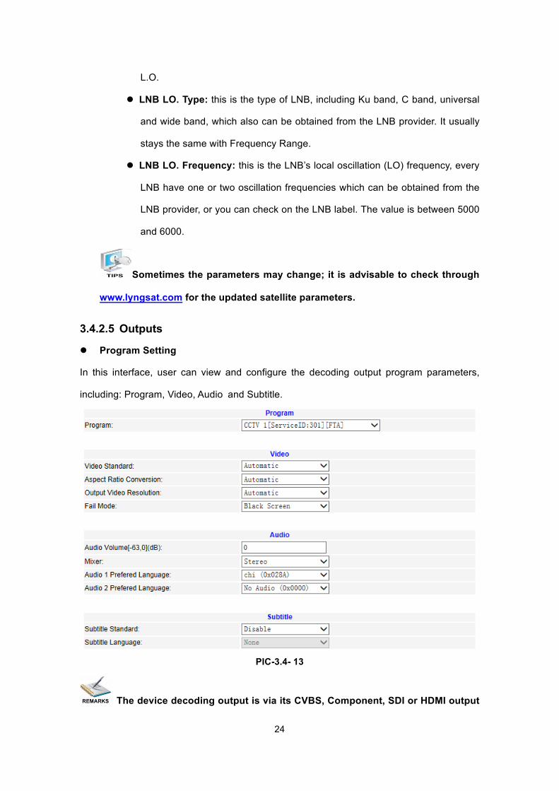
3.4.2.5 Outputs
l Program Setting
In this interface, user can view and configure the decoding output program parameters,
including: Program, Video, Audio and Subtitle.
PIC-3.4- 13
The device decoding output is via its CVBS, Component, SDI or HDMI output
25
ports. For each time only one program can be set to decoding output.
The parameters set in “Program Setup” interface work for all selected
program.
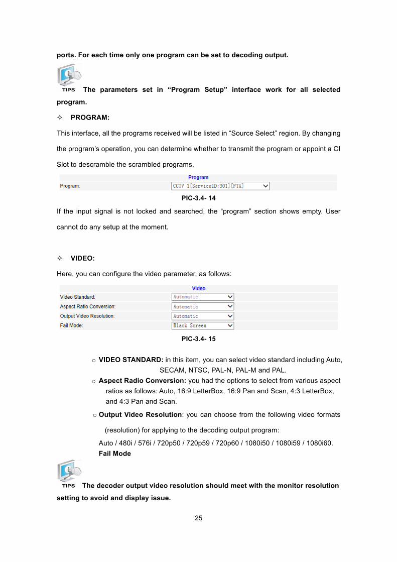
² PROGRAM:
This interface, all the programs received will be listed in “Source Select” region. By changing
the program’s operation, you can determine whether to transmit the program or appoint a CI
Slot to descramble the scrambled programs.
PIC-3.4- 14
If the input signal is not locked and searched, the “program” section shows empty. User
cannot do any setup at the moment.
² VIDEO:
Here, you can configure the video parameter, as follows:
PIC-3.4- 15
o VIDEO STANDARD: in this item, you can select video standard including Auto,
SECAM, NTSC, PAL-N, PAL-M and PAL. o Aspect Radio Conversion: you had the options to select from various aspect
ratios as follows: Auto, 16:9 LetterBox, 16:9 Pan and Scan, 4:3 LetterBox, and 4:3 Pan and Scan.
o Output Video Resolution: you can choose from the following video formats
(resolution) for applying to the decoding output program:
Auto / 480i / 576i / 720p50 / 720p59 / 720p60 / 1080i50 / 1080i59 / 1080i60. Fail Mode
The decoder output video resolution should meet with the monitor resolution
setting to avoid and display issue.
26
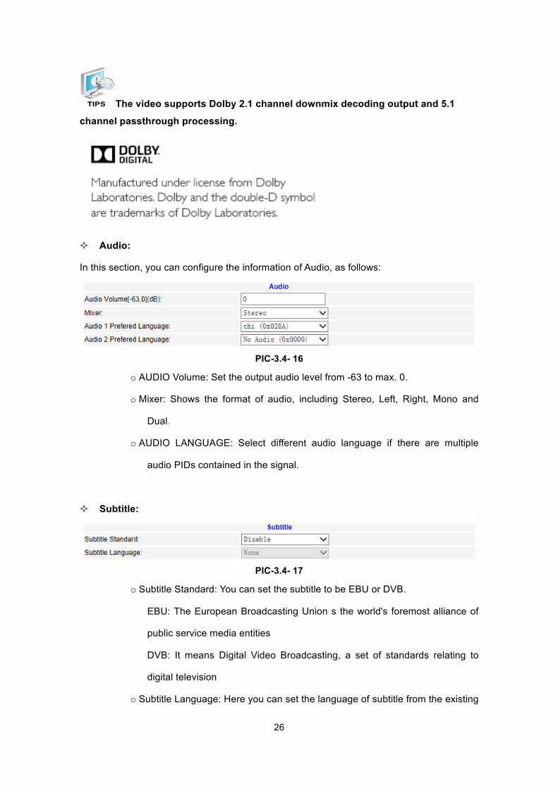
The video supports Dolby 2.1 channel downmix decoding output and 5.1
channel passthrough processing.
² Audio:
In this section, you can configure the information of Audio, as follows:
PIC-3.4- 16
o AUDIO Volume: Set the output audio level from -63 to max. 0.
o Mixer: Shows the format of audio, including Stereo, Left, Right, Mono and
Dual.
o AUDIO LANGUAGE: Select different audio language if there are multiple
audio PIDs contained in the signal.
² Subtitle:
PIC-3.4- 17
o Subtitle Standard: You can set the subtitle to be EBU or DVB.
EBU: The European Broadcasting Union s the world's foremost alliance of
public service media entities
DVB: It means Digital Video Broadcasting, a set of standards relating to
digital television
o Subtitle Language: Here you can set the language of subtitle from the existing
27
selections.
The decoder can decode Closed Caption (CEA608 /CEA708) and output from
CVBS and SDI interface or passthrough through ASI and IP.
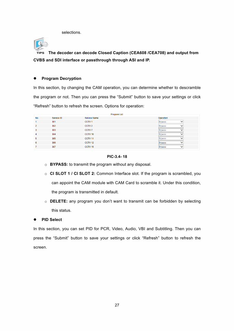
l Program Decryption
In this section, by changing the CAM operation, you can determine whether to descramble
the program or not. Then you can press the “Submit” button to save your settings or click
“Refresh” button to refresh the screen. Options for operation:
PIC-3.4- 18
o BYPASS: to transmit the program without any disposal.
o CI SLOT 1 / CI SLOT 2: Common Interface slot. If the program is scrambled, you
can appoint the CAM module with CAM Card to scramble it. Under this condition,
the program is transmitted in default.
o DELETE: any program you don’t want to transmit can be forbidden by selecting
this status.
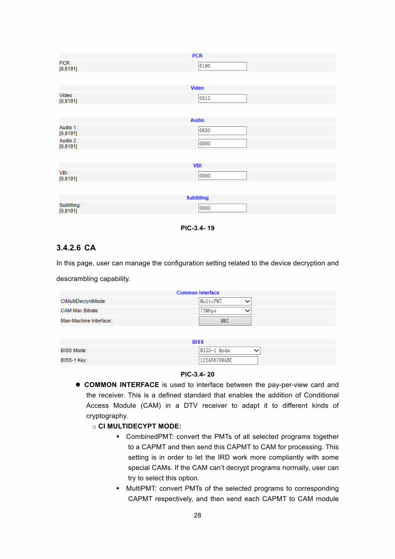
l PID Select
In this section, you can set PID for PCR, Video, Audio, VBI and Subtitling. Then you can
press the “Submit” button to save your settings or click “Refresh” button to refresh the
screen.
28
PIC-3.4- 19
3.4.2.6 CA
In this page, user can manage the configuration setting related to the device decryption and
descrambling capability.
PIC-3.4- 20
l COMMON INTERFACE is used to interface between the pay-per-view card and the receiver. This is a defined standard that enables the addition of Conditional Access Module (CAM) in a DTV receiver to adapt it to different kinds of cryptography. o CI MULTIDECYPT MODE:
§ CombinedPMT: convert the PMTs of all selected programs together to a CAPMT and then send this CAPMT to CAM for processing. This setting is in order to let the IRD work more compliantly with some special CAMs. If the CAM can’t decrypt programs normally, user can try to select this option.
§ MultiPMT: convert PMTs of the selected programs to corresponding CAPMT respectively, and then send each CAPMT to CAM module
29
for processing. This is the default setting. o CI Bitrate Mode: Set the max output bit rate of the CAM.
l BISS (Basic Interoperable Scrambling System): is a satellite signal scrambling
system developed by the European Broadcasting Union and a consortium of
hardware manufacturers. There are two types:
o BISS-1, transmission are protected by a 12 digit hexadecimal “session key” that is agreed by the transmitting and receiving parties prior to transmission. The key is entered into both the encoder and decoder, this key then forms part of the encryption of the digital TV signal and any receiver with BISS-support with correct key will decrypt the signal.
o BISS-E (E for encrypted), is a variation where the decoder has stored one secret BISS-key entered by for example a rights holder. This is unknown to the user of the decoder. The user is then sent a 16-digit hexadecimal code, which is entered as a “session key”. This session key is then mathematically combined internally to calculate a BISS-1 key that can decrypt the signal.
o BISS-E ID, an identification ID given prior to transmission and reception.
Usually a standard CAM can support Max. 72Mbit data processing unless it
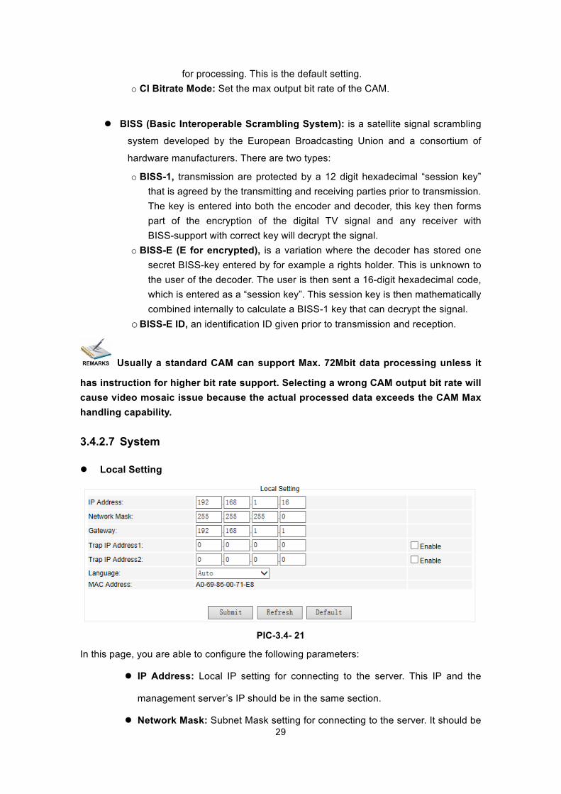
has instruction for higher bit rate support. Selecting a wrong CAM output bit rate will cause video mosaic issue because the actual processed data exceeds the CAM Max handling capability. 3.4.2.7 System l Local Setting
PIC-3.4- 21
In this page, you are able to configure the following parameters:
l IP Address: Local IP setting for connecting to the server. This IP and the
management server’s IP should be in the same section.
l Network Mask: Subnet Mask setting for connecting to the server. It should be
30
the same as management server: 255.255.255.0
l Gateway: Gateway setting for connecting to the server. It should be the same
as the management server.
l Trap IP Address1: This IP should be the same as the monitoring server’s IP.
After correct setup, the IRD will pass the alarming and running information to
the monitoring server.
l Trap IP Address2: This IP should be the same as the monitoring server’s IP.
After correct setup, the IRD will pass the alarming and running information to
the monitoring server.
l Language: select the required language from these options. There are 4
default options: auto, English, Russia, Chinese.
l Mac Address: Here shows the MAC address of the device. The MAC address
is fixed and not editable.
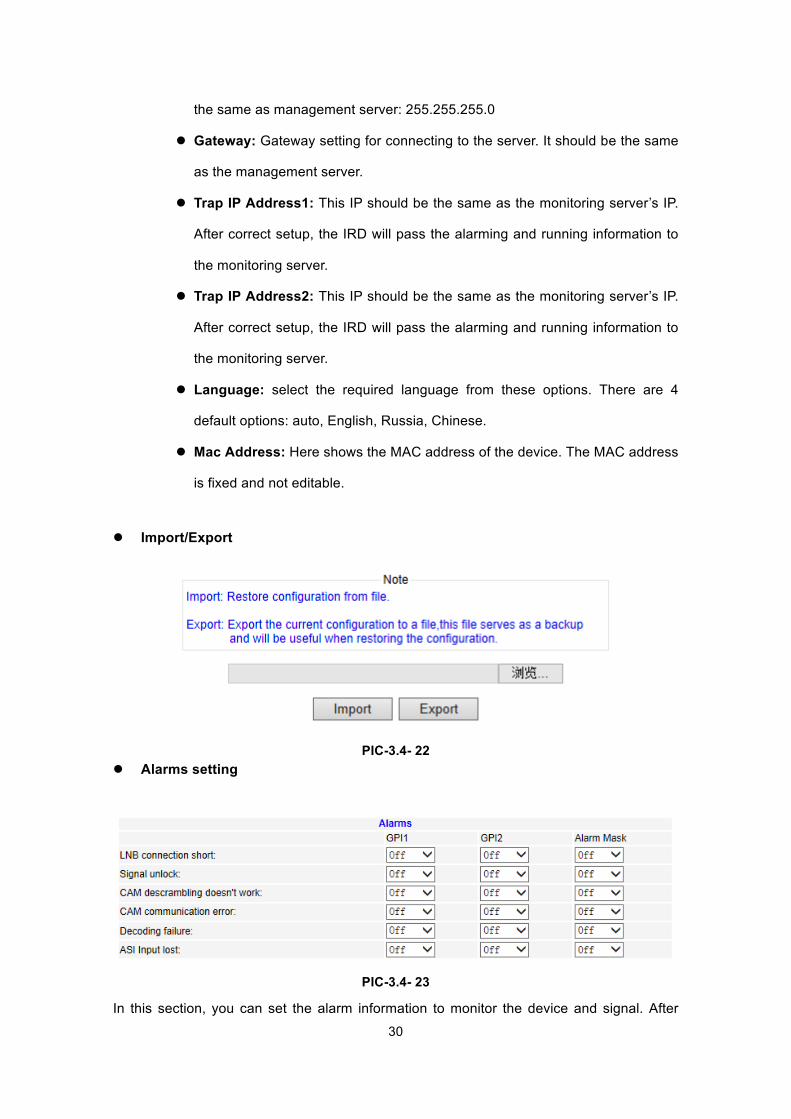
l Import/Export
PIC-3.4- 22 l Alarms setting
PIC-3.4- 23
In this section, you can set the alarm information to monitor the device and signal. After
31
setting the “Alarm Mask” on, the “GPI” item will be optional. If you set the GPI on, when
there are LNB Disconnect, Signal unlocked, CAM error, decoder failure, ASI output lost error,
the alarm information will be sent out via GPI.
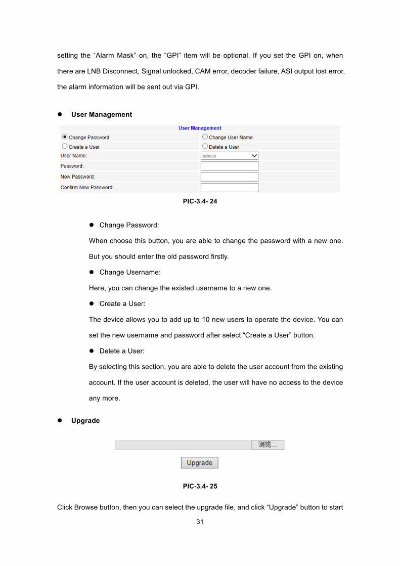
l User Management
PIC-3.4- 24
l Change Password:
When choose this button, you are able to change the password with a new one.
But you should enter the old password firstly.
l Change Username:
Here, you can change the existed username to a new one.
l Create a User:
The device allows you to add up to 10 new users to operate the device. You can
set the new username and password after select “Create a User” button.
l Delete a User:
By selecting this section, you are able to delete the user account from the existing
account. If the user account is deleted, the user will have no access to the device
any more.
l Upgrade
PIC-3.4- 25
Click Browse button, then you can select the upgrade file, and click “Upgrade” button to start
32
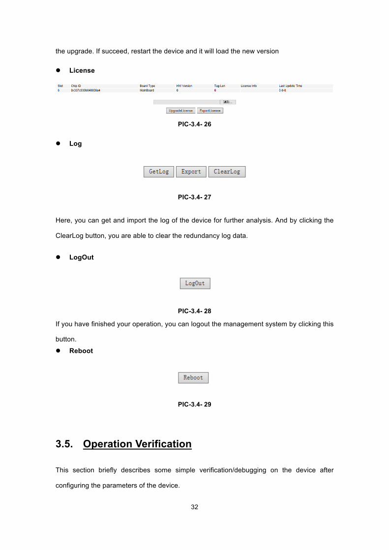
the upgrade. If succeed, restart the device and it will load the new version l License
PIC-3.4- 26
l Log
PIC-3.4- 27
Here, you can get and import the log of the device for further analysis. And by clicking the
ClearLog button, you are able to clear the redundancy log data.
l LogOut
PIC-3.4- 28
If you have finished your operation, you can logout the management system by clicking this
button.
l Reboot
PIC-3.4- 29
3.5. Operation Verification
This section briefly describes some simple verification/debugging on the device after
configuring the parameters of the device.
33
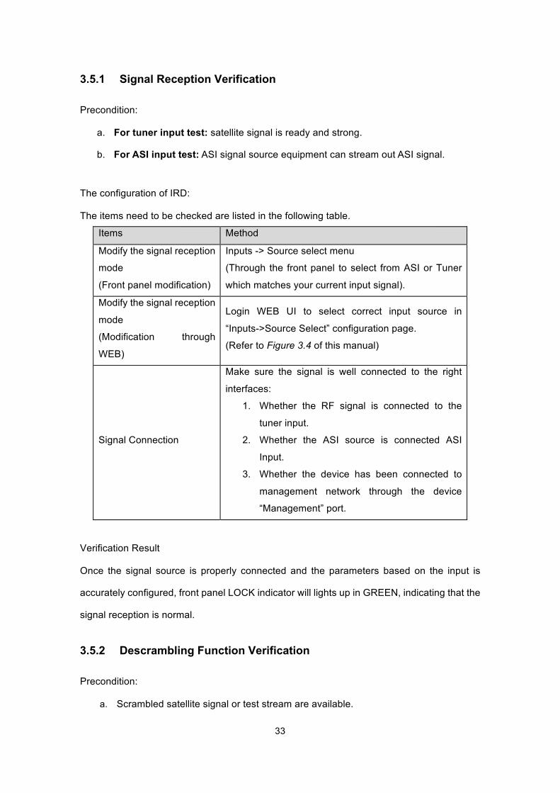
3.5.1 Signal Reception Verification
Precondition:
a. For tuner input test: satellite signal is ready and strong.
b. For ASI input test: ASI signal source equipment can stream out ASI signal.
The configuration of IRD:
The items need to be checked are listed in the following table.
Items Method
Modify the signal reception
mode
(Front panel modification)
Inputs -> Source select menu
(Through the front panel to select from ASI or Tuner
which matches your current input signal).
Modify the signal reception
mode
(Modification through
WEB)
Login WEB UI to select correct input source in
“Inputs->Source Select” configuration page.
(Refer to Figure 3.4 of this manual)
Signal Connection
Make sure the signal is well connected to the right
interfaces:
1. Whether the RF signal is connected to the
tuner input.
2. Whether the ASI source is connected ASI
Input.
3. Whether the device has been connected to
management network through the device
“Management” port.
Verification Result
Once the signal source is properly connected and the parameters based on the input is
accurately configured, front panel LOCK indicator will lights up in GREEN, indicating that the
signal reception is normal.
3.5.2 Descrambling Function Verification
Precondition:
a. Scrambled satellite signal or test stream are available.
34
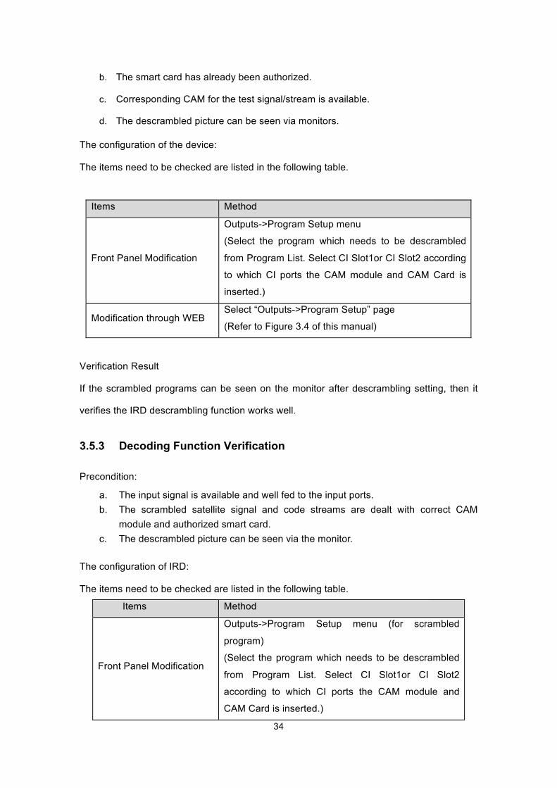
b. The smart card has already been authorized.
c. Corresponding CAM for the test signal/stream is available.
d. The descrambled picture can be seen via monitors.
The configuration of the device:
The items need to be checked are listed in the following table.
Items Method
Front Panel Modification
Outputs->Program Setup menu
(Select the program which needs to be descrambled
from Program List. Select CI Slot1or CI Slot2 according
to which CI ports the CAM module and CAM Card is
inserted.)
Modification through WEB Select “Outputs->Program Setup” page
(Refer to Figure 3.4 of this manual)
Verification Result
If the scrambled programs can be seen on the monitor after descrambling setting, then it
verifies the IRD descrambling function works well.
3.5.3 Decoding Function Verification
Precondition:
a. The input signal is available and well fed to the input ports. b. The scrambled satellite signal and code streams are dealt with correct CAM
module and authorized smart card. c. The descrambled picture can be seen via the monitor.
The configuration of IRD:
The items need to be checked are listed in the following table.
Items Method
Front Panel Modification
Outputs->Program Setup menu (for scrambled
program)
(Select the program which needs to be descrambled
from Program List. Select CI Slot1or CI Slot2
according to which CI ports the CAM module and
CAM Card is inserted.)
35
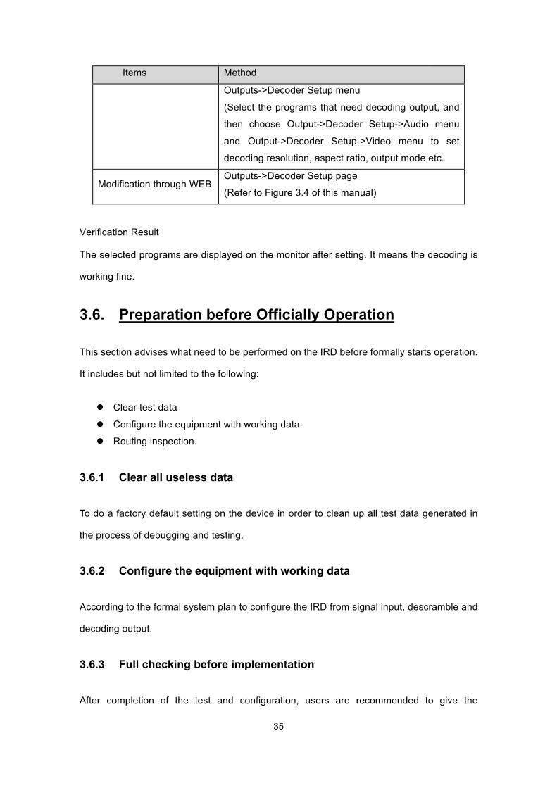
Items Method
Outputs->Decoder Setup menu
(Select the programs that need decoding output, and
then choose Output->Decoder Setup->Audio menu
and Output->Decoder Setup->Video menu to set
decoding resolution, aspect ratio, output mode etc.
Modification through WEB Outputs->Decoder Setup page
(Refer to Figure 3.4 of this manual)
Verification Result
The selected programs are displayed on the monitor after setting. It means the decoding is
working fine.
3.6. Preparation before Officially Operation
This section advises what need to be performed on the IRD before formally starts operation.
It includes but not limited to the following:
l Clear test data
l Configure the equipment with working data.
l Routing inspection.
3.6.1 Clear all useless data
To do a factory default setting on the device in order to clean up all test data generated in
the process of debugging and testing.
3.6.2 Configure the equipment with working data
According to the formal system plan to configure the IRD from signal input, descramble and
decoding output.
3.6.3 Full checking before implementation
After completion of the test and configuration, users are recommended to give the
36
equipment a final full-scale checking to ensure everything is on track for working with
long-term stability. It shall contain (but not limited to) the following items:
l Check the strength and quality of all input signals. l Check if there is any alarm lights up on front panel LED indicator. l Check whether the cable connection is in good condition with each external device.
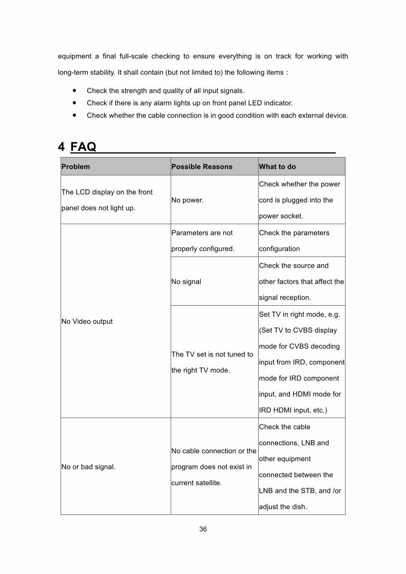
4 FAQ Problem Possible Reasons What to do
The LCD display on the front
panel does not light up. No power.
Check whether the power
cord is plugged into the
power socket.
No Video output
Parameters are not
properly configured.
Check the parameters
configuration
No signal
Check the source and
other factors that affect the
signal reception.
The TV set is not tuned to
the right TV mode.
Set TV in right mode, e.g.
(Set TV to CVBS display
mode for CVBS decoding
input from IRD, component
mode for IRD component
input, and HDMI mode for
IRD HDMI input, etc.)
No or bad signal.
No cable connection or the
program does not exist in
current satellite.
Check the cable
connections, LNB and
other equipment
connected between the
LNB and the STB, and /or
adjust the dish.
37
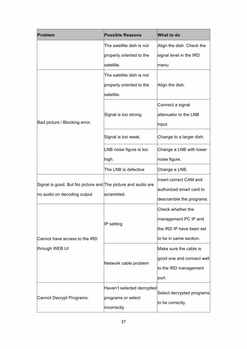
Problem Possible Reasons What to do
The satellite dish is not
properly oriented to the
satellite.
Align the dish. Check the
signal level in the IRD
menu.
Bad picture / Blocking error.
The satellite dish is not
properly oriented to the
satellite.
Align the dish.
Signal is too strong.
Connect a signal
attenuator to the LNB
input.
Signal is too weak. Change to a larger dish.
LNB noise figure is too
high.
Change a LNB with lower
noise figure.
The LNB is defective Change a LNB.
Signal is good. But No picture and
no audio on decoding output
The picture and audio are
scrambled.
Insert correct CAM and
authorized smart card to
descramble the programs.
Cannot have access to the IRD
through WEB UI
IP setting
Check whether the
management PC IP and
the IRD IP have been set
to be in same section.
Network cable problem
Make sure the cable is
good one and connect well
to the IRD management
port.
Cannot Decrypt Programs.
Haven’t selected decrypted
programs or select
incorrectly.
Select decrypted programs
to be correctly.
38
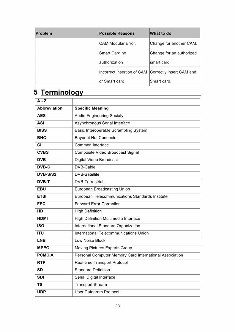
Problem Possible Reasons What to do
CAM Modular Error. Change for another CAM.
Smart Card no
authorization
Change for an authorized
smart card
Incorrect insertion of CAM
or Smart card.
Correctly insert CAM and
Smart card.
5 Terminology
A - Z
Abbreviation Specific Meaning
AES Audio Engineering Society
ASI Asynchronous Serial Interface
BISS Basic Interoperable Scrambling System
BNC Bayonet Nut Connector
CI Common Interface
CVBS Composite Video Broadcast Signal
DVB Digital Video Broadcast
DVB-C DVB-Cable
DVB-S/S2 DVB-Satellite
DVB-T DVB-Terrestrial
EBU European Broadcasting Union
ETSI European Telecommunications Standards Institute
FEC Forward Error Correction
HD High Definition
HDMI High Definition Multimedia Interface
ISO International Standard Organization
ITU International Telecommunications Union
LNB Low Noise Block
MPEG Moving Pictures Experts Group
PCMCIA Personal Computer Memory Card International Association
RTP Real-time Transport Protocol
SD Standard Definition
SDI Serial Digital Interface
TS Transport Stream
UDP User Datagram Protocol