Embed Size (px)
Citation preview

Programmable Logic Controllers (PLC) in the Packaging Industry: an Object Oriented Approach for Developing Control Programs
Manuel Pineda-Sanchez, Marina Pérez-Vázquez, Ángel Sapena-Bañó, Javier Martinez-Román, Juan Pérez-Cruz, Rubén Puche-Panadero, Victor Pérez-Vázquez
Universitat Politècnica de València/Dept. of Electrical Engineering
Camino de Vera s/n, 46022 Valencia, Spain
[email protected], [email protected], [email protected], [email protected], [email protected], [email protected], [email protected]
ABSTRACT
Packaging automated industry is based on PLC control systems. Most of them are IEC 61131-3 PLC compliant. The standard was the first step to introduce Object Oriented Programming (OOP) features in the PLC based automation such as encapsulation in Function Blocks. Nevertheless, other major benefits of OOP such inheritance, or polymorphism weren’t defined. On the other hand, the standard was born with the aim of create a unique structure of PLC programs providing a way to exchange programs between several PLC brands. However this goal is far from being achieved. In this paper, a new approach to include these OOP benefits is proposed. Besides, programs developed within this framework can be adapted with minimum effort and maximum reliability to different packaging.
INTRODUCTION
Programmable Logic Controllers (PLC) are key components in modern packaging automation systems. Before the adoption of the IEC61131-3 standard, each PLC brand developed its own and particular programmable languages and rules. Incompatibilities among the different tools made it very difficult to port the control program of a packaging machine from one PLC brand to a different one, so that the same program had to be almost completely rewritten [1]. To solve these problems, the IEC standard [2] defined five programming languages: Instruction list (IL), Ladder diagram (LD), Function Block Diagram (FBD), Sequential Function Chart (SFC) and Structured Text (ST). Besides, the IEC standard has also defined new elements to structure the program, such as Function Blocks (FBs), Program Units (POUs), User Defined Data Types (UDT), etc.
The simple class FB contained in the standard has internal state and it may be instantiated several times [3] in the Program and also brings some benefits of Objected Oriented Programming (OOP) as encapsulation. Nevertheless, in most PLC brands, other major benefits of OOP are not supported (generic programming, polymorphism, etc.), and even some of the OOP features defined by the standard may not be available, such as inheritance. Recent works have applied OOP concepts to development of PLC software [4, 5, 6, 7, 8] through the use of FB. Besides, several research groups have used the UML and XML languages in order to generate PLC code that implements OOP approaches such as abstraction and general programming [9, 10].
Nevertheless there is still a lack of reusability of code between different PLC brands. As [11] stages only CoDeSys V3 can be used for programming a significant number of industrial devices (see [12]
for further details) from different PLC brands such as Telemecanique, Festo. Moreover, it supports PLCOpen XML import/export functionality that allows the user to exchange the code between different PLC brands, achieving a significant reusability and adaptability of PLC objects.
What is proposed in this paper is a new multilevel and modular framework for developing flexible PLC programs which offer the following advantages: an inheritance mechanism is proposed (objects can inherit properties from other objects), the objects have the same structure and they can be imported or replaced in any part of the program seamlessly. Programs developed within this framework can be adapted with minimum effort and maximum reliability to different packaging machines. Besides, the objects can share information with the SCADA system for supervision, quality control, and other information related purposes.
This paper is structured as follows, first the basic elements and its structure is showed. Secondly an example which use this objects to control and axis is displayed and finally the conclusions are presented.
OBJECT ORIENTED PLC OBJECTS
The objects are defined following a physical model, the relay component, having the same properties of the relays used in modern electrical cabinets. Physical relays are split in two components, a single type of connecting base, common to all types of relays (which ensures direct replacement of parts), and a specific control block which is plugged into the base, and implements the functionality of each type of relay. Besides, following the physical model, a new conductor component is defined. This conductor can carry any kind of signal defined in the IEC standard (Bool, Integer, Real, Time, etc.), and it is used to connect the objects regardless the kind of signals due to the standard common base.
WIRES
As in electrical cabinets, the components are connected to each other through wires. Hence, in this paper three levels of wires are defined User Defined Data types. The definition of these three levels allows the user to apply different OOP features:
a) Conductor: Polymorphism
The conductor data-type has a direct physical counterpart. A physical copper or aluminum wire, for example, can carry data of different types: digital, analog, even data frames multiplexed in the
386 IEEE Catalog Number: CFP1459B-ART ISBN: 978-1-4799-7727-7
time or frequency domain. In the same way, the conductor object, as defined in Figure 1, can carry any type of the elemental data defined in the IEC 61131-3 standard. There is a drawback in this definition: the size of a conductor structure is the sum of the size of each elemental data type that it can hold. The solution to this problem could be the addition of a new data structure to the standard, included in modern OOPLC languages such as C++: the “union” type, whose size is only the largest size of any of its elements.
FIGURE 1: CONDUCTOR STRUCTURE.
b) Cable: Parallelism
Connections of different elements inside an electrical control cabinet are made with conductors, but these are normally grouped, forming cables. This technique helps to speed up the building of new systems and to reduce connection-related bugs. Conductors are grouped forming cables, and relays are grouped in cards. Array connectors fasten the connection of relays and cards between them and with external inputs and outputs. A new element is used in OOPLC to represent a physical cable: the cable data type, defined as an array of four conductors, as shown in Figure 2.
FIGURE 2: CABLE STRUCTURE.
c) Line: Parallelism
In the same way conductors are grouped forming cables, cables may be grouped in a level superior forming lines. Hence using the same technique it is possible to build other groups of elements.
RELAYS
The electrical cabinets have different types of relays with different functionalities (Figure 3). Based on these elements reusable object oriented objects are developed. The OOPLC model of a physical relay has two components, as its physical counterpart: the external interface, or the “base”, which is common to every relay, and its internal components, or “control unit”, which is specific to each one.
The base relay element defines the common set of connections. Physical relays are connected using conductors, which can carry signals of different types (digital, analog), even mixed ones using time or frequency multiplexing technology. Figure 4 shows the parts of a physical relay.
FIGURE 3: RELAYS MOUNTED IN AN ELECTRICAL CABINET.
FIGURE 4: LEFT, BASE RELAY. RIGHT, CONTROL UNIT RELAY.
a) Base relay: Generic Programming or Template
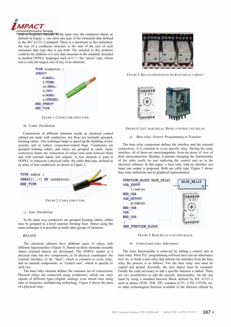
The base relay component defines the interface and the external connections. It is common to every specific relay. Having the same interface, all of them are interchangeable, from the point of view of their interconnection. Besides, it permits changing the functionality of the relay easily by just replacing the control unit as in the electrical cabinets. In this paper, a base relay with an interface one input one output is proposed. Both are cable type. Figure 5 shows base relay definition and its graphical representation.
FIGURE 5: BASE RELAY FUNCTION BLOCK.
b) Control unit relay: Inheritance
The relay functionality is achieved by adding a control unit to base relay. Most PLC programming software have not an inheritance tool. So, to build a new relay that inherits the interface from the base relay the process is as follows. Firs the base relay unit must be copied and pasted. Secondly, the new object must be renamed. Finally the code necessary to add a specific function is added. There are two possibilities to add the specific functionality. On the one hand by using a standard function Block defined by IEC 61131-3 such as timers (TON, TOF, TP), counters (CTU, CTD, CTUD), etc. or other technological function available in the libraries offered by
387IEEE Catalog Number: CFP1459B-ART ISBN: 978-1-4799-7727-7

the manufacturers. On the other hand creating its own function block or adding the code to relay. Figure 6 shows an example of relay which his specific function is the timer TON defined in the standard.
FIGURE 6: RELAY WITH CONTROL UNIT FUNCTION BLOCK.
c) Cards: Derivate elements and parallelism
As wires can be grouped, the relays are grouped in cards. Card is a derivate element of relay which exploits parallelism processing characteristics. The card has it physical counterpart similar as cards in computers which are composed of different types of chips with the same or different function and the external interface is the same for every card. Figure 7 shows an example of a basic card where the interface is common to every card (input, output) and the functionality is added by choosing the relays included in the card.
FIGURE 7: CARD OF RELAYS FUNCTION BLOCK.
EXAMPLE OF APPLICATION
Using the approach proposed in this paper a classical object in the packaging machinery is solved: the control of one axis. The axis has the following sensors connected to the PLC: a position sensor and two digital limit switches. Moreover, two digital signal are used in order to start and stop the axis movement. On the other hand it has another analog signal to indicate the desired final position of the axis, i.e. to indicate which movement must do the axis. As outputs it has 4 digital outputs, once for start the movement, twice to indicate the direction (forward or reverse). The last one is for changing the speed, when the axis is close to the desired speed the motor moves slowly increasing the precision.
This example is solved using two relays. The former is used to convert the electrical analog signal from the position sensor of the axis into length (Figure 8).
FIGURE 8: RELAY TO CONVERT ELECTRICAL ANALOG SIGNALS TO OTHER MAGNITUDES.
The second relay controls the axis movements as it is showed in
Figure 9. It is remarkable that with this new approach the system can be easily scaled and applied to control a large number of axes by using a card of relays which is useful in packaging machinery.
FIGURE 9: RELAY AXIS FUNCTION BLOCK.
388 IEEE Catalog Number: CFP1459B-ART ISBN: 978-1-4799-7727-7

CONCLUSIONS
The encapsulation is OOP benefit exploited by this new approach. Every function or function block can be encapsulated forming a relay. Thus every element has the common interface and connections are made easily using the same type of conductors, which can carry any data type. It is similar to container used in packaging systems, which can transport any load. Hence tools used to move, manipulate, etc. function blocks proposed can be designed without any type constraints. The main benefits of the proposed standardization are cost reduction, generic tools, faster manipulation, simplified management and reusability. This approach takes advantage of other OOP benefits such as polymorphism, generic programming, parallelism and inheritance. The objects proposed can be easily extended to adapt the system to different applications, and can be effortlessly adapted to different PLC brands.
REFERENCES
[1] A. Otto and K. Hellmann, “IEC 61131: A general overview and emerging trends,” Industrial Electronics Magazine, IEEE, vol. 3, no. 4, pp. 27–31, Dec 2009.
[2] Programmable Controllers–Part3: Programming languages, International Electrotechnical Commission, IEC Std., 2003.
[3] K. Thramboulidis and G. Frey, “An MDD process for IEC 61131-based industrial automation systems,” in Emerging Technologies Factory Automation (ETFA), 2011 IEEE 16th Conference on, Sept 2011, pp. 1–8.
[4] V. Vyatkin, J. Christensen, and J. Lastra, “Oooneida: an open, object-oriented knowledge economy for intelligent industrial automation,” Industrial Informatics, IEEE Transactions on, vol. 1, no. 1, pp. 4–17, Feb 2005.
[5] B. Werner, “Object-oriented extensions for iec 61131-3,” Industrial Electronics Magazine, IEEE, vol. 3, no. 4, pp. 36–39, Dec 2009.
[6] M. Bonfe and C. Fantuzzi, “Object-oriented approach to plc software design for a manufacture machinery using iec 61131-3 norm languages,” in Advanced Intelligent Mechatronics, 2001. Proceedings. 2001 IEEE/ASME International Conference on, vol. 2, 2001, pp. 787–792 vol.2.
[7] U. Schunemann, “Programming plcs with an object-oriented approach,” ATP International, Automation Technology In Practice, no. 2, pp. 59–63, 2007.
[8] V. González, A. Sierra Diaz, P. García Fernández, A. Fernández Junquera, and R. Mayo Bayón, “Mioop. an object oriented programming paradigm approach on the iec 61131 standard,” in Emerging Technologies and Factory Automation (ETFA), 2010 IEEE Conference on, Sept 2010, pp. 1–4.
[9] K. Thramboulidis, “Towards an object-oriented extension for iec 61131,” in Emerging Technologies Factory Automation (ETFA), 2012 IEEE 17th Conference on, Sept 2012, pp. 1–8.
[10] N. Papakonstantinou and S. Sierla, “Generating an object oriented iec 61131-3 software product line architecture from sysml,” in Emerging Technologies Factory Automation (ETFA), 2013 IEEE 18th Conference on, Sept 2013, pp. 1–8.
[11] F. Basile, P. Chiacchio, and D. Gerbasio, “On the implementation of industrial automation systems based on plc,” Automation Science and Engineering, IEEE Transactions on, vol. 10, no. 4, pp. 990–1003, Oct 2013.
[12] 3s smart software solutions, codesys v3 2014. [Online]. Available: http://www.3s-software.com
389IEEE Catalog Number: CFP1459B-ART ISBN: 978-1-4799-7727-7