Embed Size (px)
Citation preview
Web Site: www.parallax.com Forums: forums.parallax.com Sales: [email protected] Technical: [email protected]
Office: (916) 624-8333 Fax: (916) 624-8003 Sales: (888) 512-1024 Tech Support: (888) 997-8267
Copyright © Parallax Inc. Propeller Proto Board (#32212), USB (32812) Accessory Kit (122-32212) v1.3 2/3/2010 Page 1 of 4
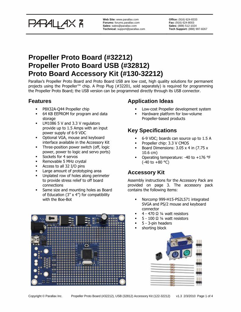
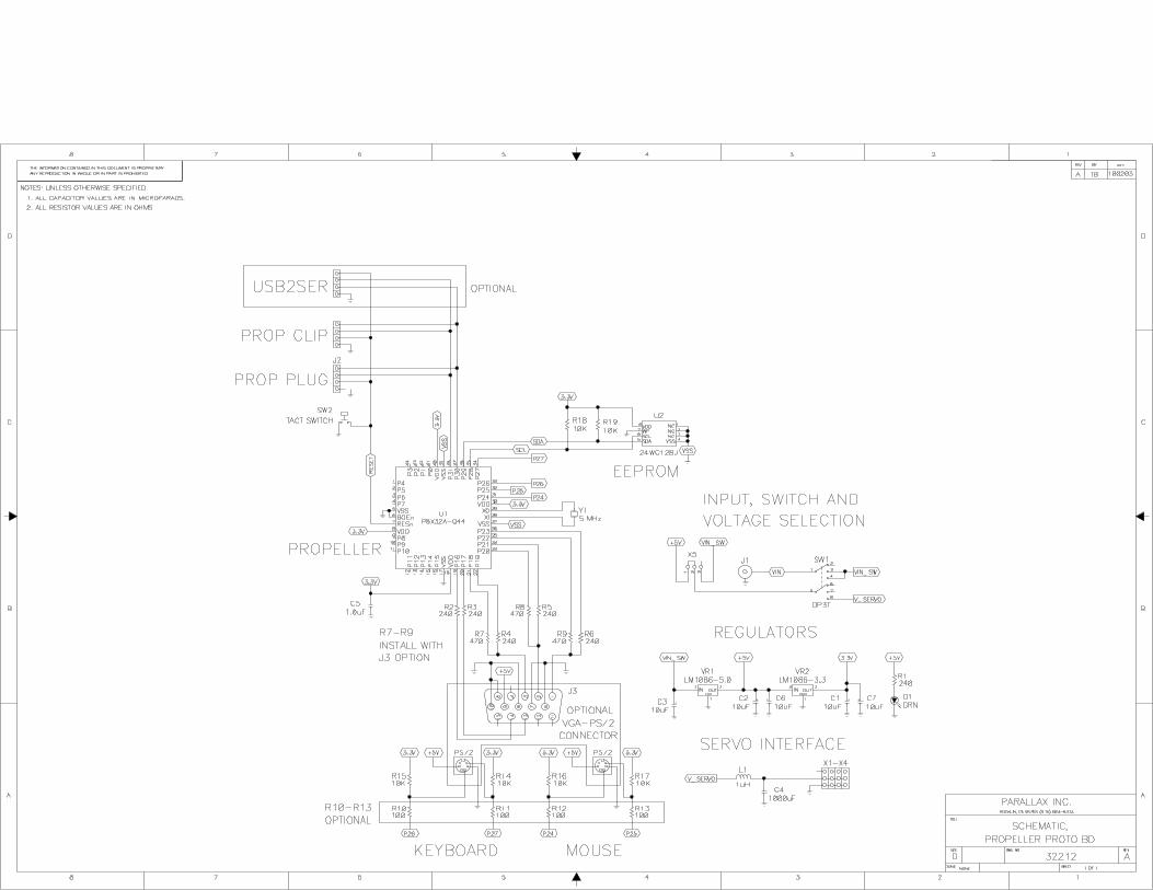
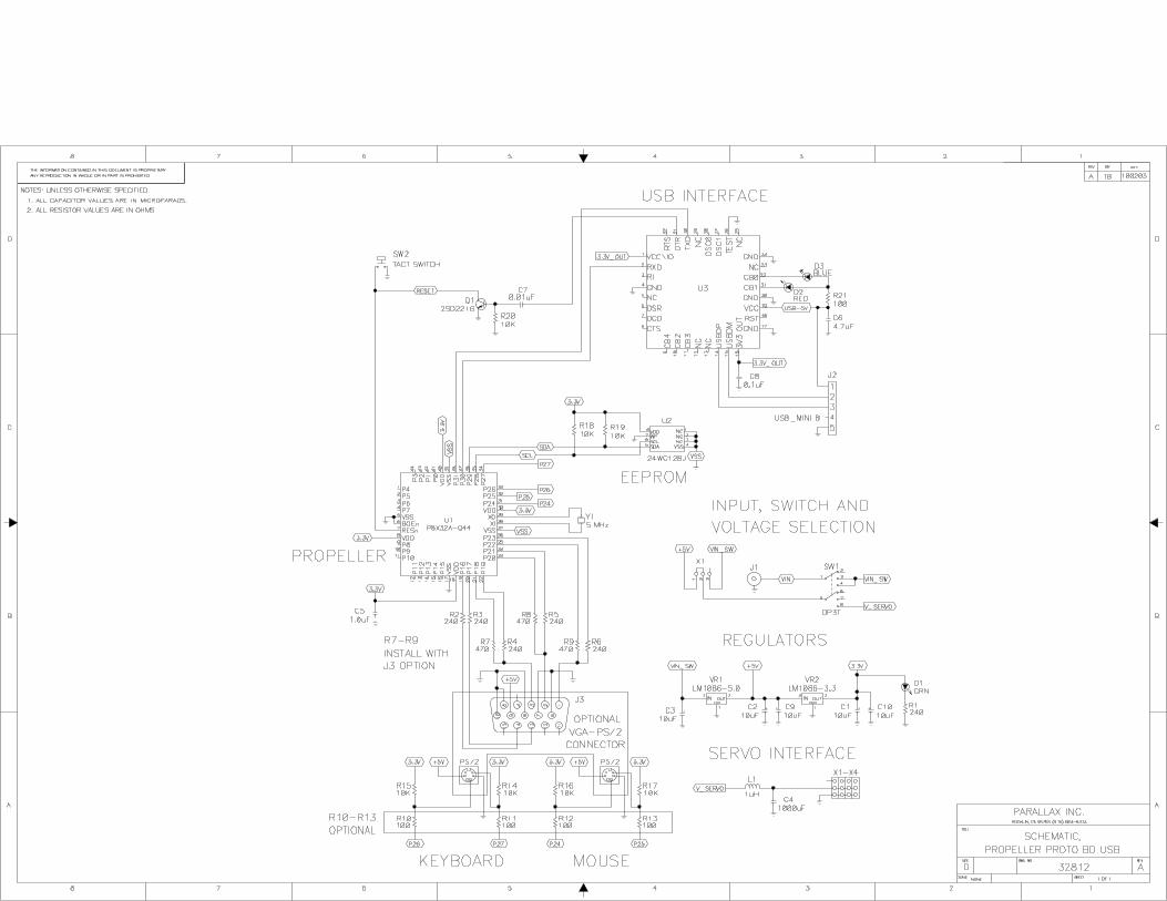
Propeller Proto Board (#32212) Propeller Proto Board USB (#32812) Proto Board Accessory Kit (#130-32212) Parallax’s Propeller Proto Board and Proto Board USB are low cost, high quality solutions for permanent projects using the Propeller™ chip. A Prop Plug (#32201, sold separately) is required for programming the Propeller Proto Board; the USB version can be programmed directly through its USB connector. Features
P8X32A-Q44 Propeller chip 64 KB EEPROM for program and data
storage LM1086 5 V and 3.3 V regulators
provide up to 1.5 Amps with an input power supply of 6-9 VDC
Optional VGA, mouse and keyboard interface available in the Accessory Kit
Three-position power switch (off, logic power, power to logic and servo ports)
Sockets for 4 servos Removable 5 MHz crystal Access to all 32 I/O pins Large amount of prototyping area Unplated row of holes along perimeter
to provide stress relief to off board connections
Same size and mounting holes as Board of Education (3” x 4”) for compatibility with the Boe-Bot
Application Ideas Low-cost Propeller development system Hardware platform for low-volume
Propeller-based products Key Specifications
6-9 VDC; boards can source up to 1.5 A Propeller chip: 3.3 V CMOS Board Dimensions: 3.05 x 4 in (7.75 x
10.6 cm) Operating temperature: -40 to +176 °F
(-40 to +80 °C)
Accessory Kit Assembly instructions for the Accessory Pack are provided on page 3. The accessory pack contains the following items:
Norcomp 999-H15-PS2L571 integrated SVGA and PS/2 mouse and keyboard connector
4 - 470 Ω ¼ watt resistors 5 - 100 Ω ¼ watt resistors 5 - 3-pin headers shorting block
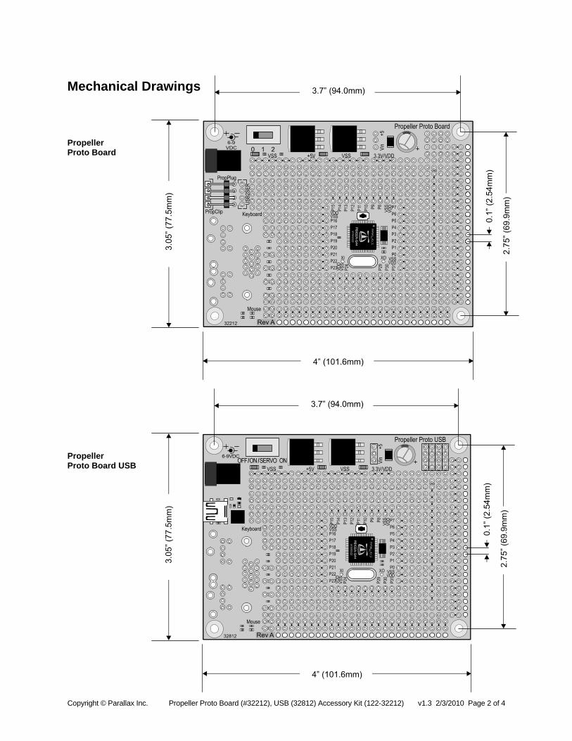
Mechanical Drawings
Propeller Proto Board Propeller Proto Board USB
Copyright © Parallax Inc. Propeller Proto Board (#32212), USB (32812) Accessory Kit (122-32212) v1.3 2/3/2010 Page 2 of 4
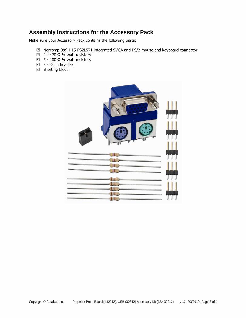
Assembly Instructions for the Accessory Pack Make sure your Accessory Pack contains the following parts:
Norcomp 999-H15-PS2L571 integrated SVGA and PS/2 mouse and keyboard connector 4 - 470 Ω ¼ watt resistors 5 - 100 Ω ¼ watt resistors 5 - 3-pin headers shorting block
Copyright © Parallax Inc. Propeller Proto Board (#32212), USB (32812) Accessory Kit (122-32212) v1.3 2/3/2010 Page 3 of 4
Copyright © Parallax Inc. Propeller Proto Board (#32212), USB (32812) Accessory Kit (122-32212) v1.3 2/3/2010 Page 4 of 4
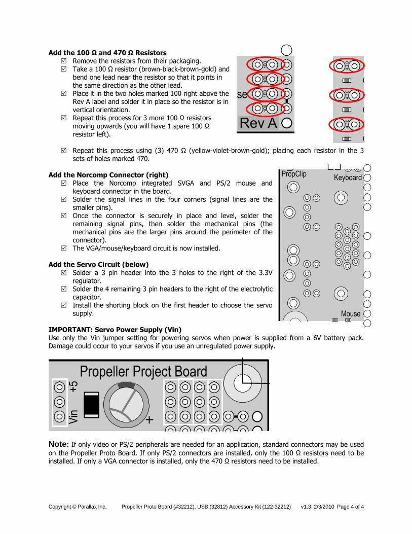
Add the 100 Ω and 470 Ω Resistors Remove the resistors from their packaging. Take a 100 Ω resistor (brown-black-brown-gold) and
bend one lead near the resistor so that it points in the same direction as the other lead.
Place it in the two holes marked 100 right above the Rev A label and solder it in place so the resistor is in vertical orientation.
Repeat this process for 3 more 100 Ω resistors moving upwards (you will have 1 spare 100 Ω resistor left).
Repeat this process using (3) 470 Ω (yellow-violet-brown-gold); placing each resistor in the 3
sets of holes marked 470. Add the Norcomp Connector (right)
Place the Norcomp integrated SVGA and PS/2 mouse and keyboard connector in the board.
Solder the signal lines in the four corners (signal lines are the smaller pins).
Once the connector is securely in place and level, solder the remaining signal pins, then solder the mechanical pins (the mechanical pins are the larger pins around the perimeter of the connector).
The VGA/mouse/keyboard circuit is now installed. Add the Servo Circuit (below)
Solder a 3 pin header into the 3 holes to the right of the 3.3V regulator.
Solder the 4 remaining 3 pin headers to the right of the electrolytic capacitor.
Install the shorting block on the first header to choose the servo supply.
IMPORTANT: Servo Power Supply (Vin) Use only the Vin jumper setting for powering servos when power is supplied from a 6V battery pack. Damage could occur to your servos if you use an unregulated power supply.
Note: If only video or PS/2 peripherals are needed for an application, standard connectors may be used on the Propeller Proto Board. If only PS/2 connectors are installed, only the 100 Ω resistors need to be installed. If only a VGA connector is installed, only the 470 Ω resistors need to be installed.

Introduction to the Propeller Protoboard A step-by-step tutorial for new users By Jeff Ledger August 2008
Welcome to the world of microcontrollers!
You have the ticket to an exciting adventure. The Parallax Propeller chip is the stamp sized
square in the center of your Protoboard. It is one of the most advanced, yet easiest-to-use
microcontrollers ever created.
A microcontroller is simply a one-chip computer. Microcontrollers can be found running
everyday devices from your microwave to your stove and even the gas pumps at your local
service station. The Propeller microcontroller is capable of video, sound, input controllers, and
communication with a variety of sensors. By adding some simple electronics to your
Protoboard, you can do everything from predicting the weather to playing video games.
The purpose of this document is to get you up and running with exactly what you have in your
hands, the Parallax Propeller Protoboard, and the programming Prop plug.
You will need to download the following programs to your computer:
Propeller Tool http://www.parallax.com/tabid/442/Default.aspx
Propterminal http://www.insonix.ch/propeller/objects/PropTerminal_0.4.zip
FemtoBASIC for Propterminal http://jeffledger.googlepages.com/FemtoBasic_Propterminal.zip
The Propeller Manual (requires a .PDF reader)
http://www.rayslogic.com/propeller/Propeller%20Manual%20v1.01bmarked.pdf
The Propeller Tool is the official programming environment (IDE) for the Propeller and is
provided free of charge. We'll use it to load programs from the computer into the Propeller.
The electronic form manual is also provided free of charge. You may want to invest in a printed
copy from Parallax as you start programming in "spin", the language used in the Propeller Tool.
We will use Propterminal to simulate the keyboard and video on the computer because we do not
have these connections on the Protoboard. They are easy to add later. Propterminal will allow
you to use the computer keyboard and screen as if they were connected directly to the Propeller
itself.

Part 2: Getting Started
You'll need to get a DC power adapter. Any DC adapter which has an output of 6v-9v (center
positive) should work fine with your Protoboard. Radio Shack sells a multi voltage power
supply that works perfectly. The ideal voltage setting is 7.5v.
Regulated and Filtered Universal 300mA AC Adapter $18.99 (1.5-12v DC 300mA) http://www.radioshack.com/product/index.jsp?productId=2552559&cp
Install the Propeller Tool software first. After it is installed, run the program. Answer yes to
"Associate .spin .binary and .eeprom files." Close the program once when is done. (Double
clicking any .spin file will open it correctly now.)
Special Note: Some computer configurations have drive letter assignments for things like SD, MMC cards, etc that
may not be in use when you start the Propeller tool. As a result you might get a "Propeller Tool: Propeller.exe - No Disk" message. It is caused by the tool attempting to talk to those drive letters. Just click "Cancel" until it goes
away. It won’t hurt anything and there is a fix for it in the forums.
Now let's get ready to connect the Protoboard. First, make sure the
surface on which you have set your Protoboard is non-conductive
because the board could “short-out” when you turn it on. Next, plug the
USB cable side of the Prop-plug into your computer and plug itself face
up into the four pin connector on the Protoboard. Connect the power
supply and switch the Protoboard on. Don't worry about being shocked
by your Protoboard because it operates on battery voltages and is
generally considered safe to touch. You should have a bright green light.
Unzip the Propterminal and FemtoBASIC zip files into their own folders.
Let's start with a simple demo.
Look for Scroll_Demo in the Propterminal folder. Double click this file which should now open
in the Propeller Tool. Switch on your Protoboard and hit F11. This will send the program into
the eeprom on your Protoboard.
The EEPROM is the tiny chip next to the Propeller chip in the center of your Protoboard.
The eeprom will store your program even when the power is off. Each time you switch on the
Protoboard it will load the Scroll_Demo until you use the Propeller Tool (F11) to upload a new
program.
Hit F7 in the Propeller Tool and make a mental or written note of the COM port number.
It will say "Propeller chip version 1 found on COM#"

Now that you have programmed your Protoboard, close the Propeller Tool and launch the
program Propterminal from the Propterminal folder. The first time you run this program, you
will get the message, "COM port not found." Click OK, Options, and Com-port. Change the
“6” to the number reported in the last step. (F7 in Propeller Tool) Click on File, and Save Settings. Propterminal is now configured for your setup.
Make sure your Protoboard is still switched on. Close and restart Propterminal. Press the tiny
reset button on your Protoboard. (The reset button is located above the Propeller chip in the
center of your Protoboard.)
If you see the words "Scroll Demo..." and a small Propeller graphic, Congratulations!
The program is running on your Propeller, and Propterminal is acting as a small video
screen for your Protoboard.
Let's take things a little further...
Close Propterminal and open the file PC_Interface_Demo. It should open in the Propeller tool.
Click F11 to send this program to your Protoboard. Now open Propterminal and push the reset
button again.
This time you computer's mouse and keyboard are able to interact with the Propeller. Move your
mouse around the Propterminal window and type something. See the lights flashing on your
Prop plug? You mouse movements and keystrokes are being sent to the Propeller and the output
is sent back to Propterminal for display.
These programs are simple display & input demos. In the next step we will load a small BASIC
interpreter into your Propeller. While BASIC isn't as powerful as Spin, it will allow us to write
and run simple programs right on the Propeller itself using Propterminal as your screen and
keyboard.
Look for “FemtoBASIC Propterminal” in the FemtoBASIC folder. Double click this program
to open it in Propeller Tool and press F11 to upload it to the Protoboard.
Launch the Propterminal program and press the reset button on the Protoboard.
You should see the following words:
Propterminal FemtoBasic 2.004
READY.
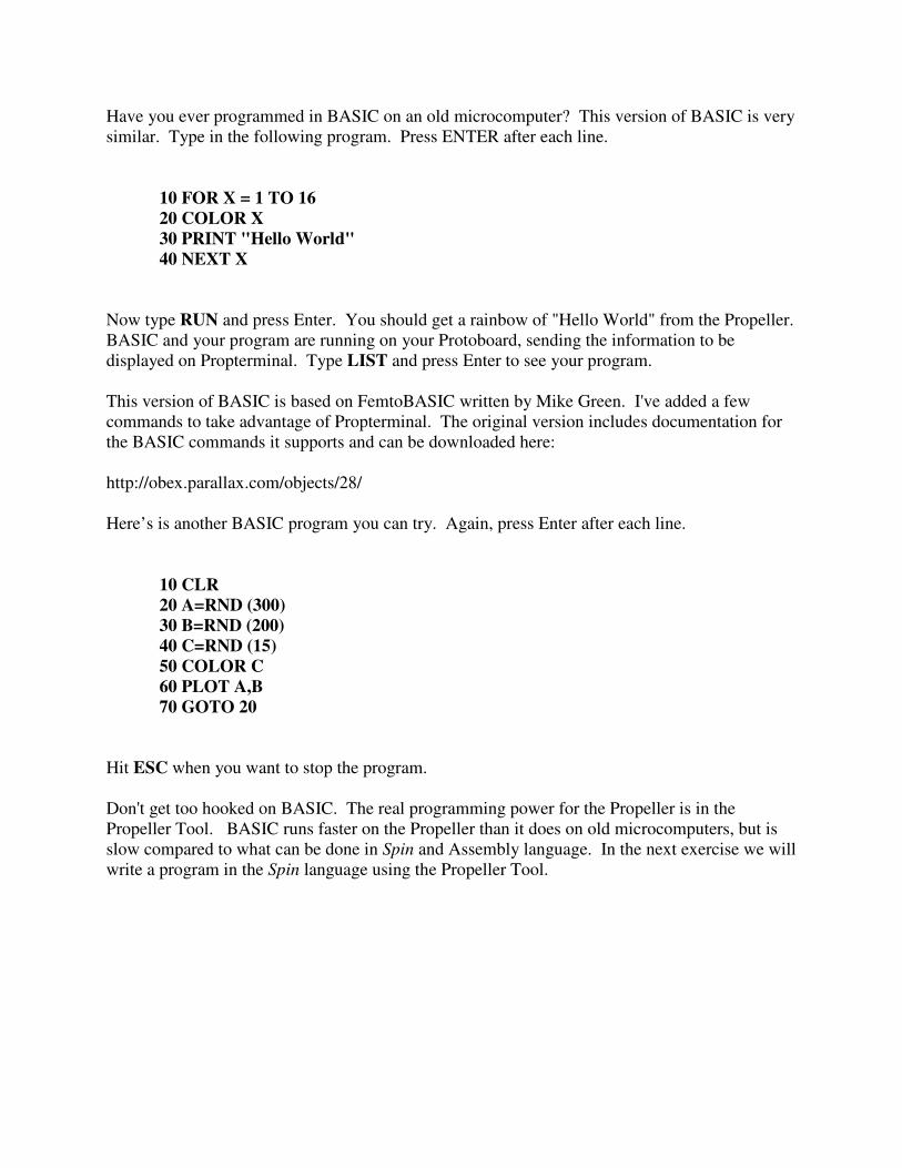
Have you ever programmed in BASIC on an old microcomputer? This version of BASIC is very
similar. Type in the following program. Press ENTER after each line.
10 FOR X = 1 TO 16 20 COLOR X 30 PRINT "Hello World" 40 NEXT X
Now type RUN and press Enter. You should get a rainbow of "Hello World" from the Propeller.
BASIC and your program are running on your Protoboard, sending the information to be
displayed on Propterminal. Type LIST and press Enter to see your program.
This version of BASIC is based on FemtoBASIC written by Mike Green. I've added a few
commands to take advantage of Propterminal. The original version includes documentation for
the BASIC commands it supports and can be downloaded here:
http://obex.parallax.com/objects/28/
Here’s is another BASIC program you can try. Again, press Enter after each line.
10 CLR 20 A=RND (300) 30 B=RND (200) 40 C=RND (15) 50 COLOR C 60 PLOT A,B 70 GOTO 20
Hit ESC when you want to stop the program.
Don't get too hooked on BASIC. The real programming power for the Propeller is in the
Propeller Tool. BASIC runs faster on the Propeller than it does on old microcomputers, but is
slow compared to what can be done in Spin and Assembly language. In the next exercise we will
write a program in the Spin language using the Propeller Tool.
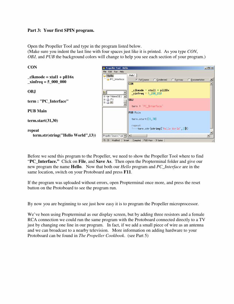
Part 3: Your first SPIN program.
Open the Propeller Tool and type in the program listed below.
(Make sure you indent the last line with four spaces just like it is printed. As you type CON,
OBJ, and PUB the background colors will change to help you see each section of your program.)
CON _clkmode = xtal1 + pll16x _xinfreq = 5_000_000 OBJ term : "PC_Interface" PUB Main term.start(31,30) repeat term.str(string("Hello World",13))
Before we send this program to the Propeller, we need to show the Propeller Tool where to find
“PC_Interface.” Click on File, and Save As. Then open the Propterminal folder and give our
new program the name Hello. Now that both our Hello program and PC_Interface are in the
same location, switch on your Protoboard and press F11.
If the program was uploaded without errors, open Propterminal once more, and press the reset
button on the Protoboard to see the program run.
By now you are beginning to see just how easy it is to program the Propeller microprocessor.
We’ve been using Propterminal as our display screen, but by adding three resistors and a female
RCA connection we could run the same program with the Protoboard connected directly to a TV
just by changing one line in our program. In fact, if we add a small piece of wire as an antenna
and we can broadcast to a nearby television. More information on adding hardware to your
Protoboard can be found in The Propeller Cookbook. (see Part 5)
Part 4: Interacting with the real world.
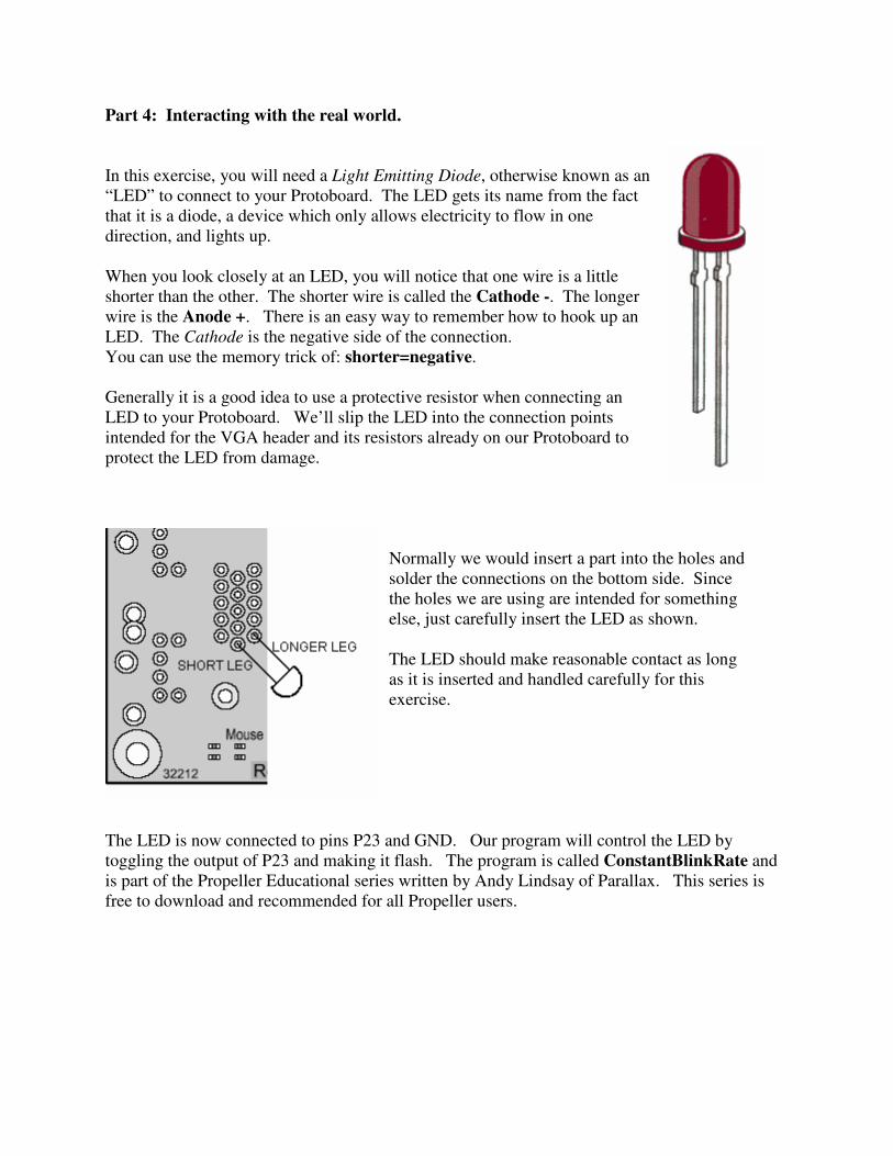
In this exercise, you will need a Light Emitting Diode, otherwise known as an
“LED” to connect to your Protoboard. The LED gets its name from the fact
that it is a diode, a device which only allows electricity to flow in one
direction, and lights up.
When you look closely at an LED, you will notice that one wire is a little
shorter than the other. The shorter wire is called the Cathode -. The longer
wire is the Anode +. There is an easy way to remember how to hook up an
LED. The Cathode is the negative side of the connection.
You can use the memory trick of: shorter=negative.
Generally it is a good idea to use a protective resistor when connecting an
LED to your Protoboard. We’ll slip the LED into the connection points
intended for the VGA header and its resistors already on our Protoboard to
protect the LED from damage.
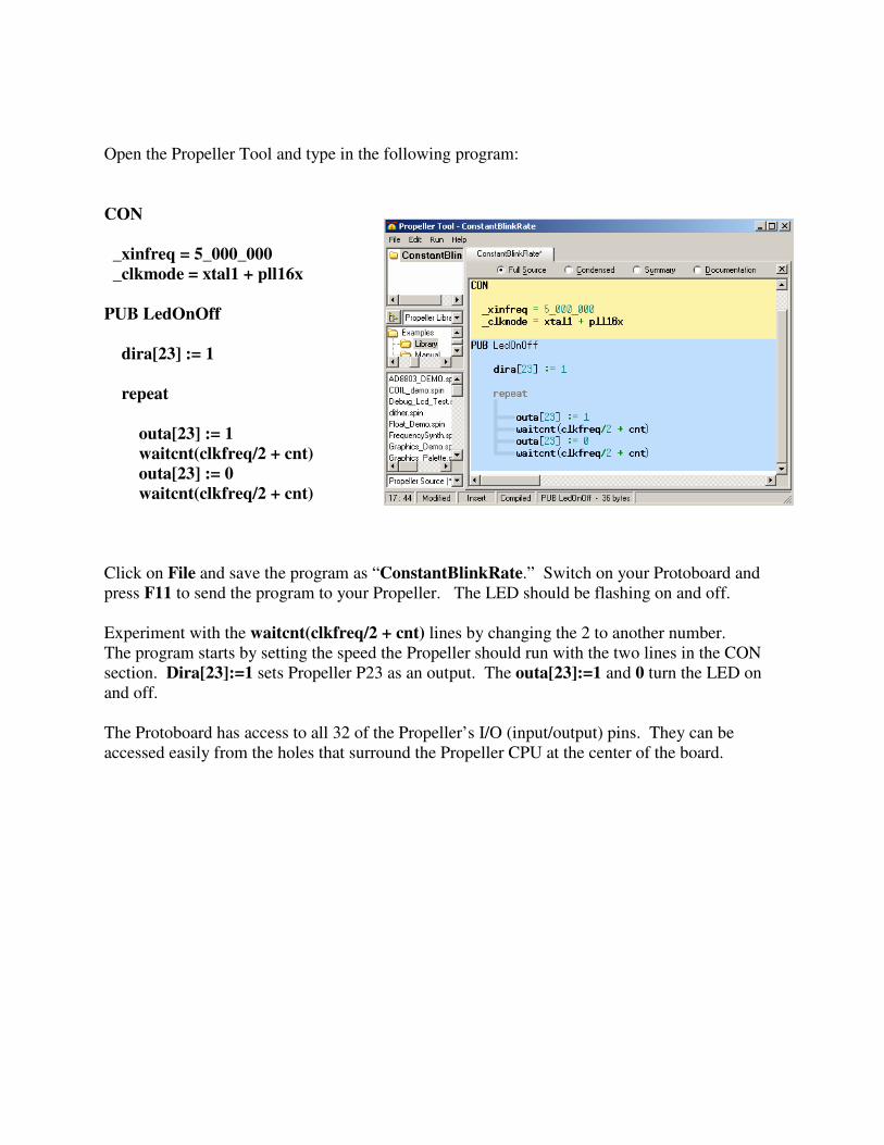
Normally we would insert a part into the holes and
solder the connections on the bottom side. Since
the holes we are using are intended for something
else, just carefully insert the LED as shown.
The LED should make reasonable contact as long
as it is inserted and handled carefully for this
exercise.
The LED is now connected to pins P23 and GND. Our program will control the LED by
toggling the output of P23 and making it flash. The program is called ConstantBlinkRate and
is part of the Propeller Educational series written by Andy Lindsay of Parallax. This series is
free to download and recommended for all Propeller users.
Open the Propeller Tool and type in the following program:
CON _xinfreq = 5_000_000 _clkmode = xtal1 + pll16x PUB LedOnOff dira[23] := 1 repeat outa[23] := 1 waitcnt(clkfreq/2 + cnt) outa[23] := 0 waitcnt(clkfreq/2 + cnt)
Click on File and save the program as “ConstantBlinkRate.” Switch on your Protoboard and
press F11 to send the program to your Propeller. The LED should be flashing on and off.
Experiment with the waitcnt(clkfreq/2 + cnt) lines by changing the 2 to another number.
The program starts by setting the speed the Propeller should run with the two lines in the CON
section. Dira[23]:=1 sets Propeller P23 as an output. The outa[23]:=1 and 0 turn the LED on
and off.
The Protoboard has access to all 32 of the Propeller’s I/O (input/output) pins. They can be
accessed easily from the holes that surround the Propeller CPU at the center of the board.

Part 5: Where do I go from here?
These instructions have allowed you to dip your toes into the world of microcontrollers.
We have only scratched the surface of what is possible with a Parallax Propeller chip.
Take a look at this list of projects: You are only limited only by your imagination.
http://www.warrantyvoid.us/projects.html
You will want to add some simple electronics to your Protoboard to do many of the exciting
projects enjoyed by Propeller enthusiasts. The Propeller Cookbook is recommended reading.
The Propeller Cookbook http://www.warrantyvoid.us/PPDftB.html
http://ucontroller.com/Propeller%20Protoboard%20Designs%20for%20the%20Beginner.pdf
The Propeller Forums http://forums.parallax.com/forums/default.aspx?f=25
Need some help? The Propeller Forums are a friendly online environment filled with all levels
of experience and knowledge. Questions are encouraged. Log in and introduce yourself.
The search engine built into the Parallax Forums doesn’t work very well, so I recommended to
using http://search.parallax.com.
Questions posted to the forum should be as complete as possible. Do not skip the subject entry.
The Propeller Wiki Many common questions are answered in the user created Propeller Wiki.
http://propeller.wikispaces.com
The Propeller Object Exchange The Object Exchange is a growing collection of software for the Propeller.
http://obex.parallax.com
Credits: This document is maintained by Jeff Ledger. (Oldbitcollector)
Questions should be directed to the Propeller Forums.
Propterminal was written by Andy Schenk. (Ariba)
http://forums.parallax.com/forums/default.aspx?f=25&m=189805
The Original FemtoBASIC was written by Tomas Rokicki,


![Propeller Board of Education 32900 A - docs-emea.rs-online.com filePropeller Clock Input (XI ) Propeller Reset (RST) Multi- purpose Sock et Sock et.SchDoc DA0 DA1 P[0..27] AD0 AD1](https://img.pdfslide.net/doc/110x75/5d139bb988c993f6138bce27/propeller-board-of-education-32900-a-docs-emears-clock-input-xi-propeller.jpg)