Embed Size (px)
Citation preview
Prospects of ion projection techniques formaskless implantation at high ion energies
Jan Meijer*, Andreas Stephan
Institut f€uur Physik mit Ionenstrahlen, Ruhr-Universit€aat Bochum, D-44780 Bochum, Germany
Abstract
Structured ion implantation using surface contact masks has limits at high substrate temperature or high fluences.
Maskless processes can be performed by two different methods of structured implantation: single focused spot scanning
and the ion projection technique. While at low ion energies both methods are established the realisation of ion pro-
jection for MeV ions is quite new. The main ion optical element used in this technique is the final lens, that allows the
focussing of high energy ions with a lateral resolution down to a few hundred nanometers. Besides lens design
and aberration control, the development of stencil masks and alignment procedures are the major topics to be con-
sidered.
This paper gives an overview of maskless implantation techniques and describes the status of the high energy ion
projection method. Ion optical properties of high energy lens systems and their limits are discussed. � 2002 Elsevier
Science B.V. All rights reserved.
PACS: 41.75; 41.85; 61.72; 85.40.H
Keywords: Ion projection; Maskless implantation; Ion beam optics
1. Introduction
Ion beam modification of materials e.g. dopingof semiconductors has become an important fab-rication technique manly driven by industrialneeds. Commercial implanters allow accurate ionfluence determination, easy handling and fast pro-cessing in a wide range of applications. New re-quirements such as high lateral resolution at highion energies or the need to process materials such
as diamond at very high substrate temperaturelead to further developments of the establishedimplantation techniques. Contact mask technologyis not applicable, if the implantation is performed athigh implantation temperatures, high fluences oronto clean and non-flat surfaces. A sufficient sepa-ration between mask and target or maskless im-plantation is necessary under these conditions. Thesimplest maskless implantation technique usessingle beam spot writing with beam scanning con-trolled by a pattern generator.Focussing systems for the production of single
beam spots can divided into a low (<200 keV) anda high energy regime (>200 keV). For low energiesa combination of an electron microscope column
Nuclear Instruments and Methods in Physics Research B 188 (2002) 9–17
www.elsevier.com/locate/nimb
*Corresponding author. Tel.: +49-234-32-27310; fax: +49-
234-32-14172.
E-mail address:[email protected] (J. Meijer).
0168-583X/02/$ - see front matter � 2002 Elsevier Science B.V. All rights reserved.
PII: S0168-583X(01 )01002-3

and a high brightness liquid metal ion source isused. Such focused ion beam (FIB)-systems arewidespread in research and industry. These sys-tems provide ions with energies of 10–200 keV anda minimum focus spot size of 30 nm [1]. The mainapplications are ion deposition and sputtering, butother techniques like resist exposure and struc-tured doping can be performed. At high ion en-ergies nuclear microprobe systems can be usedas an implantation tool [2,3]. These system are acombination of a MeV accelerator and a focussinglens system. Most microprobes are optimised tofocus protons, a few systems are able to use ionsof higher masses.Single spot techniques have the advantage that
the implanted pattern can easily be changed whichis useful for prototyping of devices. Their draw-back is the sequential scanning resulting in longprocessing times, not suitable for industrial massproduction.A fast implantation method with a throughput
comparable to common broad beam techniques ision projection. This method is based on the sepa-ration of mask and target and an imaging lenssystem between both. The lens system projects thestructures of a stencil mask demagnified onto thetarget, providing both the resolution of focusedsingle spot and the throughput of a contact masktechnique. An important advantage is that thedemagnification leads to very short implantationtimes for small implantation areas. Ion projection
methods were first described by Bernheim [4].Today three projects exist using different ap-proaches. The most prominent project is the IPLdeveloped by L€ooschner, Stangl et al. [5,6]. The aimof IPL is to expose resist on wafers using protonsor He-ions with energies below 200 keV and aresolution below 50 nm. IPL aims to substitutelight exposition devices in semiconductor pro-cessing. The road map of semiconductor indus-try expects that a technique with 80 nm lateralresolution has to go into mass production in2004. The project is a joint development of a largegroup of semiconductor companies. A differentapproach is maskless microbeam reduction litho-graphy (MMRL) which is developed by a groupat Berkeley [7] at ion energies below 200 keV. Itmakes use of a computer controlled multibeamion source and allows a parallel patterning by di-rect implantation. An array of holes with indi-vidual electrodes defines the multi beamlet ionsource. A pattern generator allows to switch theseholes on and off and an ion projection systemenables the implant of demagnified patterns intothe wafer.IPL and MMRL aims to solve the 50 nm li-
thography problem using maskless implantationwhereas the high energy ion projection (HEIP)method developed at Bochum [8] allows directmaskless implantation using MeV energies and alarge choice of ions. A sketch of the set-up is givenin Fig. 1. The ion beam, defined by an aperture, is
Fig. 1. Set-up of the HEIP-system installed at Bochum. The ion beam is defined by an aperture and scanned using two separate units
over a stencil mask. The structures of the stencil mask are projected to the target using a superconducting solenoid lens.
10 J. Meijer, A. Stephan / Nucl. Instr. and Meth. in Phys. Res. B 188 (2002) 9–17

scanned over a stencil mask using two separatescanning units and focused onto the target usinga superconducting solenoid lens. We will reviewthe HEIP technique in detail in the followingsections.
2. Lens systems for high energy ion projection
devices
The main important part of an ion projector isthe ion lens. Ion optical lens systems can be sep-arated into two types: lenses with asymmetricand with rotational symmetric field distribution,respectively. The asymmetric field distribution ofquadrupole fields yields high focussing power.Although most proton microprobe systems usemagnetic quadrupole multiplets [9] these lens sys-tems have disadvantages if applied for masklessimplantation. Firstly, the individual quadrupolelenses of a multiplet have to be aligned to eachother with high precision in all directions in acomplicated alignment procedure. Secondly, theselenses show large spherical aberration and a smallacceptance, making them less attractive as an ionprojector. The use of iron yokes in magneticquadrupole lenses inhibits a precise pre-set of thefocussing field and requires time-consumingfocussing procedures when changing ion speciesor ion energy. Whereas quadruple systems can berealised with electric and magnetic fields, a field ofhigh rotational symmetry with sufficient focussingpower can be obtained by a superconductingmagnetic solenoid, only.The solenoid lens shows the so-called weak-
focussing and thus requires high field strength, butit is easy to align and shows about one orderof magnitude smaller spherical aberration com-pared to quadrupole lenses. Solenoid lensesallow short focal lengths and large acceptance.The focussing power of a given lens is defined bythe magnetic field strength only and can be eas-ily changed with high precision and reproducibil-ity. A disadvantage is that this lens type requiresa superconducting coil with high precision wind-ings.However, superconducting magnetic lenses are
the only choice for single spot scanning ion im-
plantation as well as for ion projection with highenergy ions.
2.1. Ion optical properties of the superconductingsolenoid lens
For a quadrupole field, the field vector ~BB andthe velocity v of the ions with mass m and chargeq are perpendicular to each other and result in afocussing force ð€xx ¼ �ðq=mÞvzByÞ. Ion trajectoriesaffected by this force are divergent in one planeand convergent in the perpendicular plane. Atleast two separated lenses are necessary to achievean overall focussing effect. Inside the rotationalsymmetric magnetic field of a solenoid, the mag-netic field vector and the ion velocity are mainlyparallel, the resulting force €rr ¼ �ððq=2mÞBzÞ2r isweak compared to quadrupole fields. At any timethe direction of force is towards the coil axis andresults in a focussing effect. Ions penetrate thediverging magnetic field at the edges of the coilwhich causes a rotation around the lens axis, theso-called Larmor precession. This rotation pro-duces a centrifugal force away from the axis and atwo times larger magnetic force towards the axis.The resulting force is proportional to Bz and pro-portional to the Larmor precession (itself �Bz)thus proportional to B2z . For a field distributionwith the well known Glaser bell shape an analyti-cal solution [10] is available, for other field shapesray tracing calculation has to be applied to inves-tigate focussing properties. In order to reduce theimage aberrations the field distribution has to beoptimised. As calculations show a rectangular fieldshape and a short focal length show good prop-erties (Section 2.2). For the bell shape field distri-bution it can be shown analytically [10] that thesmallest focal length is defined by the half of thefield width. This suggests a design of a lens with asmall field width.However, besides minimum aberrations, the
lens has to fulfil two basic requirements: sufficientfocussing power and a small axial astigmatism.The focussing power is defined by the maximumfield strength and the width of the field. To achievea high centre field strength with a small field width,the coil diameter should be as small as possible.Maximum field strengths available today are 9 T in
J. Meijer, A. Stephan / Nucl. Instr. and Meth. in Phys. Res. B 188 (2002) 9–17 11

NbTi- and 16 T in (NbTi/Nb3Sn)-wire technology.On the other hand to achieve good rotationalsymmetry at the coil-axis and a large acceptancethe coil diameter should be large since the axialastigmatism being the most important aberrationeffect (Section 2.2) is determined by the rotationalsymmetry of the windings. A compromise betweenthese two extremes defines the optimum field dis-tribution of the coils.In addition to the coil winding design the field
shape can be influenced by shielding (an addi-tional positive aspect of shielding is a reduction ofthe field strength at the target). Shielding can beachieved in two ways: an active shield on the endof the coil using a second coil with an invertedcurrent direction or a passive magnetic shield usingiron or superconducting plates. Both techniquescreate problems with alignment and can result inpoor rotational field symmetry. Since the rota-tional symmetry of the field is crucial it is better totake care about a highly precise winding at firstand optimise the field distribution in a second stepwithin the given conditions.The superconducting solenoid used in the Bo-
chum HEIP setup achieves a centre field strengthof 8.3 T with a coil current of 100 A. The length ofthe coil is 8 cm with an inner diameter of 7.7 cm;the outer diameter is 18 cm. The resulting fieldwidth is about 12 cm resulting in a maximumfocussing power of 11 MeV u=q2 at f ¼ 20 cm. Thesystem has a room temperature bore of 5 cm dia-meter, defining the maximum acceptance.
2.2. Aberration effects
The aberrations of an ion optical lens can bedivided into two classes: axial and non-axial ab-errations. Table 1 gives an overview of the aber-rations and their dependencies. As stated abovethe aberration coefficients depend on distributionand strength of the field but also on the set-up ofthe system. The coefficients were derived from raytracing calculations combined with a least squareoptimisation. Paraxial solutions and third ordercalculations were compared in order to extract thedifferent aberration coefficients. The axial aberra-tions are the well known spherical and chromaticaberrations [11] and the axial astigmatism orparasitic astigmatism. A magnetic asymmetry ofDB=B ¼ 12 ppm on a circle of 1 cm diameter leadsto an axial astigmatism of about 1.8 lm given foran image side divergence angle of c ¼ 0:1 mradand a 30 cm focus position. For comparison:chromatic aberration is 300 nm with DE=E ¼5� 10�4 and spherical aberration contributes 40nm with this set-up. Fortunately the axial astig-matism can be corrected as described below. Thenon-axial aberrations are isotropic and anisotropiccoma, field curvature, isotropic and anisotropicastigmatism, the isotropic and anisotropic trans-versal chromatic aberration and isotropic andanisotropic distortion and parasitic distortion. Thedifferentiation between isotropic and anisotropicaberration is a peculiarity of magnetic fields andis done because of the image rotation. While the
Table 1
The dependencies of aberrations as function of the divergence aperture radius (rb) at the solenoid centre and the axis distance x at theimage plane. DE=E is the half energy resolution as given in Glaser convention [10]. The aberration coefficients are found by ray tracingcalculations for an object length of 6 m and a focal length of 0.3 m
Axial aberration
Spherical B Dds ¼ 2Br3b B ¼ 117:0 m�2
Chromatic c1 DdC ¼ 2c1 DEE rb c1 ¼ �1:03
Parasitic astigmatism a1, a2 Ddp ¼ 2ffiffiffiffiffiffiffiffiffiffiffiffiffiffiffia21 þ a22
prb a1 ¼ �5� 10�4, a2 ¼ �1:8� 10�3
Non-axial aberration
Astigmatism C, c Dda ¼ 2ðC þffiffiffiffiffiffiffiffiffiffiffiffiffiffiffiffiC2 þ c2
pÞx2rb C ¼ �3:4 m�2, c ¼ �3:1 m�2
Field curvature D Ddf ¼ Dx2rb D ¼ 22:6 m�2
Coma F, f Ddcoma ¼ 3ffiffiffiffiffiffiffiffiffiffiffiffiffiffiffiffiF 2 þ f 2
pxr2b F ¼ �6:3 m�2, f ¼ 1:6 m�2
Transversal chromatic aberration c2, c3 Ddp ¼ 2ffiffiffiffiffiffiffiffiffiffiffiffiffiffic22 þ c23
pDEE x c2 ¼ 0:013, c3 ¼ �0:48
Distortion E, e DdD ¼ 2ffiffiffiffiffiffiffiffiffiffiffiffiffiffiffiE2 þ e2
px3 E ¼ �0:23 m�2, e ¼ 3:0 m�2
Parasitic distortion a1, a2 DdpD ¼ 2ffiffiffiffiffiffiffiffiffiffiffiffiffiffiffia21 þ a22
px3 a1 ¼ �4:310�4, a2 ¼ �3:7� 10�4
12 J. Meijer, A. Stephan / Nucl. Instr. and Meth. in Phys. Res. B 188 (2002) 9–17
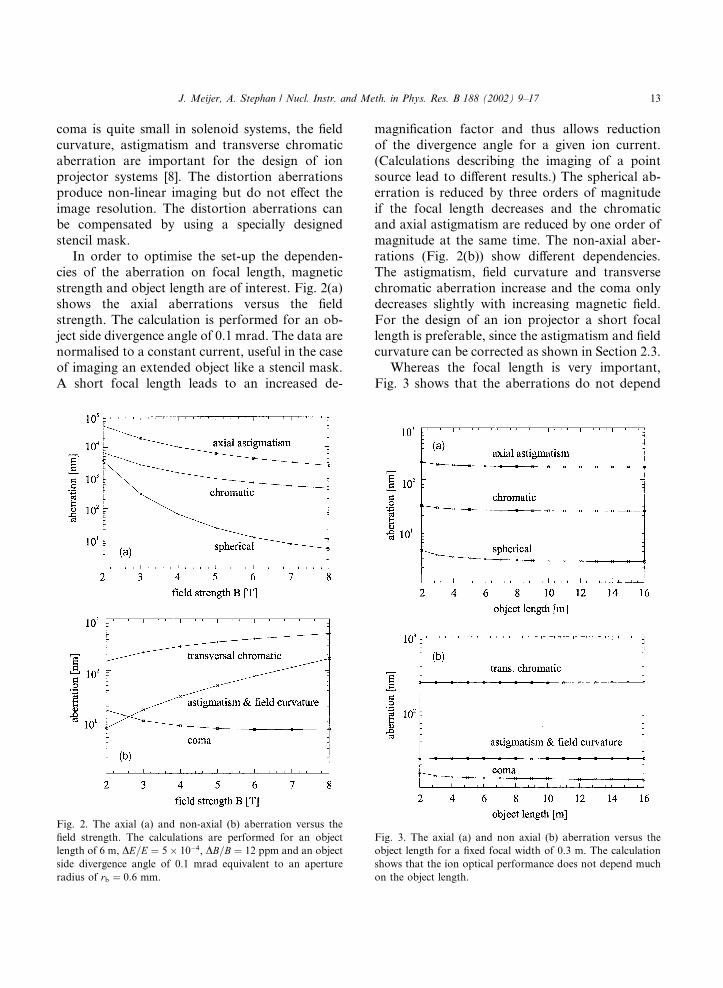
coma is quite small in solenoid systems, the fieldcurvature, astigmatism and transverse chromaticaberration are important for the design of ionprojector systems [8]. The distortion aberrationsproduce non-linear imaging but do not effect theimage resolution. The distortion aberrations canbe compensated by using a specially designedstencil mask.In order to optimise the set-up the dependen-
cies of the aberration on focal length, magneticstrength and object length are of interest. Fig. 2(a)shows the axial aberrations versus the fieldstrength. The calculation is performed for an ob-ject side divergence angle of 0.1 mrad. The data arenormalised to a constant current, useful in the caseof imaging an extended object like a stencil mask.A short focal length leads to an increased de-
magnification factor and thus allows reductionof the divergence angle for a given ion current.(Calculations describing the imaging of a pointsource lead to different results.) The spherical ab-erration is reduced by three orders of magnitudeif the focal length decreases and the chromaticand axial astigmatism are reduced by one order ofmagnitude at the same time. The non-axial aber-rations (Fig. 2(b)) show different dependencies.The astigmatism, field curvature and transversechromatic aberration increase and the coma onlydecreases slightly with increasing magnetic field.For the design of an ion projector a short focallength is preferable, since the astigmatism and fieldcurvature can be corrected as shown in Section 2.3.Whereas the focal length is very important,
Fig. 3 shows that the aberrations do not depend
Fig. 3. The axial (a) and non axial (b) aberration versus the
object length for a fixed focal width of 0.3 m. The calculation
shows that the ion optical performance does not depend much
on the object length.
Fig. 2. The axial (a) and non-axial (b) aberration versus the
field strength. The calculations are performed for an object
length of 6 m, DE=E ¼ 5� 10�4, DB=B ¼ 12 ppm and an object
side divergence angle of 0.1 mrad equivalent to an aperture
radius of rb ¼ 0:6 mm.
J. Meijer, A. Stephan / Nucl. Instr. and Meth. in Phys. Res. B 188 (2002) 9–17 13
much on the object length for a constant focalwidth. This fact is somewhat surprising becausethe demagnification is strongly dependent on theobjective length, but the equations in Table 1 showthat the aberrations depend only on the diameterof the beam at the lens centre which is equivalentto the image side divergence angle. The image sidedivergence angle and the object side divergenceangle are inversely proportional to the demagni-fication factor. For a given current density thisleads to a constant image side divergence angleand therefore to constant aberrations.
2.3. Correction of aberration
The Scherzer theorem forbids the correctionof spherical and chromatic aberration of solenoidlenses using static and symmetric correction fieldsat all [12]. Only an asymmetric electric and mag-netic field allows correction of these aberrationsup to fifth order. However, ray tracing simulationshow that the requirements concerning stabilityand precision of the correction units are extremelyhigh for high energy ion optical systems, practi-cally they are not feasible. The only suitable wayto reduce the axial chromatic aberrations is anenhancement of the energy resolution of the ionbeam. With energy stabilised accelerators in com-bination with appropriate ion sources an energyresolution of DE=E ¼ 10�5 is available today. Thisvalue reduces the chromatic aberration to negligi-ble values. The spherical aberration depends onthe third order of the divergence angle and can bereduced with an ion source of high brightness. Theadvantage of the solenoid is that these aberrationsare small compared to quadrupole systems. Theaxial astigmatism can be corrected for using smallelectric or magnetic quadrupole fields produced bya stigmator. Obviously the condition for a goodcorrection is that aberration is dominated by aquadrupole component. This is the case if thewinding errors of the solenoid coils are quite small.The correction of winding errors of higher orderis in principle possible but the diagnostic of theseaberrations is extremely complicated.Whereas for microprobe systems only the axial
aberrations are of importance, with the ion pro-jection technique also non-axial aberrations have
to be taken into account. Fortunately most non-axial aberrations can be corrected for, if the maskis only partially illuminated and the off-axis posi-tion of the ion beam is known [8,13]. Ray tracingcalculations show that a monopole correction fieldreduces the image curvature from 500 nm down to120 nm for an 8� 8 mm2 implanted field with anobject side divergence angle of 0.1 mrad and aobject length of 6 m. Astigmatism is compensatedusing an additional quadrupole field and allowsa resolution down to 80 nm. A combination ofelectric and magnetic dipole field, the so-called‘‘anti Wien filter’’, allows the correction of thetransverse chromatic aberration if the energy res-olution of the beam is poor. The correction of thecoma is complicated and requires the use of twoseparated dipole fields. Fortunately the coma isquite small for solenoid lenses and a correction isnot required. Very important is a fast diagnosticprocedure for the determination of the beamfocus. Resist on Si-substrate can be used for thispurpose. It is blackened under ion irradiation forall ion species and energies at very low fluence. Theoptical inspection system allows to routinely adjustthe HEIP set-up within 20 min and thus allowinga fast change of ion energies and ion species.
2.4. Beam resolution
The beam resolution at a given current isthe main parameter for a maskless implantationtechnique. The calculations of single aberrationgives a hint but since the combination of the ab-erration is not linear, in some cases a combinationof different aberrations cancels out. For an exactprediction of the beam spot size and distributionray tracing simulation is necessary. We developeda ray tracing program that allows the use of anykind of field distribution, as well as different elec-trostatic and magnetic lenses and multipole unitsto calculate the influence of misalignment, slit andgas scattering and alternating stray fields. How-ever, these calculations as well as the real experi-ments rise the question how to define the beamspot. In the literature the beam spot is typicallyspecified by the FWHM. Fig. 4 shows for somecalculated beam spots that the beam is not usuallya gaussian distribution e.g. if the spherical aber-
14 J. Meijer, A. Stephan / Nucl. Instr. and Meth. in Phys. Res. B 188 (2002) 9–17
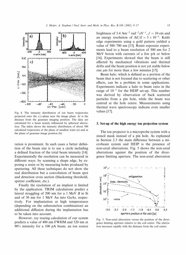
ration is prominent. In such cases a better defini-tion of the beam size is to use a circle includinga defined fraction of the total beam intensity [14].Experimentally the resolution can be measured indifferent ways: by scanning a shape edge, by ex-posing a resist or by measuring holes produced bysputtering. All these techniques do not show thereal distribution but a convolution of beam spotand detection cross section (blackening threshold,sputter coefficient, etc.).Finally the resolution of an implant is limited
by the application. TRIM calculations predict alateral straggling of 200 nm for a 1 MeV B in Siand of 30 nm for 1 MeV Au into GaAs, respec-tively. For implantation at high temperatures(depending on the substrate/ion combination) anadditional diffusion during the implantation hasto be taken into account.However, ray tracing calculation of our system
predicts a value of 400 nm FWHM and 520 nm at90% intensity for a 100 pA beam, an ion source
brightness of 3.4 Am�2 rad�2 eV�1, f ¼ 10 cm andan energy resolution of DE=E ¼ 5� 10�4. Knifeedge experiments using a gold pattern yielded avalue of 500–700 nm [15]. Resist exposure experi-ments lead to a beam resolution of 300 nm for 2MeV boron with currents of a few pA or below[16]. Experiments showed that the beam is stillaffected by mechanical vibrations and thermaldrifts and the beam position is not yet stable belowone lm for more than a few minutes [15].Beam halo, which is defined as a portion of the
beam that is not focused due to scattering or othereffects, can be a problem in some applications.Experiments indicate a halo to beam ratio in therange of 10�5 for the HEIP set-up. This numberwas derived by observation of back scatteredparticles from a pin hole, while the beam wascentred at the hole centre. Measurements usingthermal wave spectroscopy indicate even smallervalues [17].
3. Set-up of the high energy ion projection system
The ion projector is a microprobe system with astencil mask instead of a pin hole. As explainedin Section 2.3 the main difference between a mi-crobeam system and HEIP is the presence ofnon-axial aberrations. Fig. 5 shows the non-axialaberrations against the position of the diver-gence limiting aperture. The non-axial aberration
Fig. 4. The intensity distribution of ion beam trajectories
projected onto the x=y-plane near the image plane. Dz is thedistance from the gaussian imaging position. The data are
calculated for a beam mainly influenced by spherical aberra-
tion. The inlets shows the intensity distribution of about 500
calculated trajectories at the plane of smallest waist (a) and at
the plane of gaussian image position (b).
Fig. 5. Non-axial aberration versus the position of the diver-
gence limiting aperture relative to the coil centre. The aberra-
tion increases rapidly with the distance form the coil centre.
J. Meijer, A. Stephan / Nucl. Instr. and Meth. in Phys. Res. B 188 (2002) 9–17 15
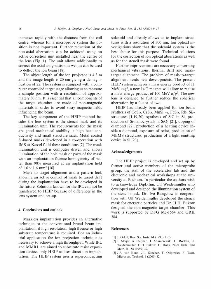
increases rapidly with the distance from the coilcentre, whereas for a microprobe system the po-sition is not important. Further reduction of thenon-axial aberration can be achieved using anactive correction unit installed near the centre ofthe lens (Fig. 1). The unit allows additionally tocorrect the axial astigmatism as well as can be usedto deflect the ion beam [18].The object length of the ion projector is 4.3 m
and the image length is 20 cm giving a demagni-fication of 22. The system is equipped with a com-puter controlled target stage allowing us to measurea sample position with a resolution of approxi-mately 30 nm. It is essential that all components ofthe target chamber are made of non-magneticmaterials in order to avoid stray magnetic fieldsinfluencing the beam.The key component of the HEIP method be-
sides the lens system is the stencil mask and itsillumination unit. The requirements for the maskare good mechanical stability, a high heat con-ductivity and small structure sizes. Metal coatedSi-based masks developed in a co-operation withIMS at Kassel fulfil these conditions [7]. The maskillumination unit is computer driven and allowsillumination of the hole mask or parts of the maskwith an implantation fluence homogeneity of bet-ter than 98% measured at an implantation fieldof 1:6� 1:6 mm2 [16].Mask to target alignment and a pattern lock
allowing an active control of mask to target driftduring the implantation have to be developed inthe future. Solutions known for the IPL can not betransferred to HEIP because of differences in thelens system and set-up.
4. Conclusions and outlook
Maskless implantation provides an alternativetechnique to the conventional broad beam im-plantation, if high resolution, high fluence or highsubstrate temperature is required. For an indus-trial application the ion projection technique isnecessary to achieve a high throughput. While IPLand MMRL are aimed to substitute resist exposi-tion devices only HEIP utilises direct ion implan-tation. The HEIP system uses a superconducting
solenoid and already allows us to implant struc-tures with a resolution of 300 nm. Ion optical in-vestigations show that the solenoid system is thebest choice for this purpose. Technical solutionsfor the correction of ion optical aberrations as wellas for the stencil mask were found.Further improvements are necessary concerning
mechanical vibrations, thermal drift and mask-target alignment. The problem of mask-to-targetalignment needs new developments. The presentHEIP system achieves a mass energy product of 11MeV u=q2, a new 14 T magnet will allow to realisea mass energy product of 100 MeV u=q2. The newlens is designed to further reduce the sphericalaberration by a factor of two.HEIP has already been applied for ion beam
synthesis of CoSi2, CrSi2, MnSi1:73, FeSi2, Rh3 Si4-structures [1,19,20], synthesis of SiC in Si, pro-duction of Si-nanocrystals in SiO2 [21], doping ofdiamond [22], production of a heating device in-side a diamond, exposure of resist, production ofMEMS structures, production of a light emittingdevice in Si [23].
Acknowledgements
The HEIP project is developed and set up byformer and active members of the microprobegroup, the staff of the accelerator lab and theelectronic and mechanical workshops at the uni-versity at Bochum. In particular the authors wishto acknowledge Dipl.-Ing. Ulf Weidenm€uuller whodeveloped and designed the illumination system ofthe stencil mask. Dr. Ivo Rangelow in coopera-tion with Ulf Weidenm€uuller developed the stencilmask for energetic particles and Dr. H.H. Bukowdesigned the non-magnetic target chamber. Thiswork is supported by DFG Me-1564 and GRK384.
References
[1] J. Orloff, Rev. Sci. Instr. 64 (1993) 1105.
[2] J. Meijer, A. Stephan, J. Adamczewski, H. R€oocken, U.
Weidenm€uuller, H.H. Bukow, C. Rolfs, Nucl. Instr. and
Meth. B 158 (1999) 39.
[3] J.A. van Kaan, J.L. Sanchez, T. Osipowics, F. Watt,
Microsyst. Technol. 6 (2000) 82.
16 J. Meijer, A. Stephan / Nucl. Instr. and Meth. in Phys. Res. B 188 (2002) 9–17

[4] M. Bernheim, Radiat. Eff. 44 (1979) 11.
[5] A. Chalupka, J. Fegerl, R. Fischer, G. Lammer,
H. L€ooschner, L. Malek, R. Nowak, G. Stangl, C. Traher,P. Wolf, Microelectron. Eng. 17 (1992) 229.
[6] J. Melngailis, A.A. Mondelli, I.L. Berry III, R. Mohondro,
J. Vac. Sci. Technol. B 16 (3) (1998) 927.
[7] V.V. Ngo, W. Barletta, K. Gough, Y. Lee, K.N. Leung,
N. Zahir, J. Vac. Sci. Technol. B 17 (6) (1999) 2783.
[8] J.Meijer, A. Stephan,Microelectron. Eng. 41/42 (1998) 257.
[9] J.A. Cookson, A.T.G. Ferguson, F.D. Pilling, Radioanal.
Chem. 12 (1972) 39.
[10] W. Glaser, Grundlagen der Elektronenoptik, Springer,
Wien, 1952.
[11] P.W. Hawkes, E. Kasper, Principles of Electron Optics,
Harcourt Brace Jovanovich, New York, 1989.
[12] O. Scherzer, Z. Phys. 101 (1937) 593.
[13] A.V. Crewe, N.W. Parker, Optik 46 (1976) 183.
[14] Y.L. Wang, Z. Shao, Adv. Electron. Electron Phys. 81
(1991) 177.
[15] A. Stephan, J. Meijer, J. Adamczewski, H. R€oocken, D.
L€ooffelmacher, H.H. Bukow, C. Rolfs, Nucl. Instr. and
Meth. B 113 (1996) 387.
[16] U. Weidenm€uuller, J. Meijer, A. Stephan, H.H. Bukow,
C. Rolfs, E. Sossna, B. Volland, I.W. Rangelow, Vac. Sci.
Technol., in press.
[17] D. Diezel, J. Bolte, H. R€oocken, J. Pelzl, B.K. Bein, Surf.
Coat. Technol., 143–144 (2001) 429.
[18] J. Meijer, A. Stephan, German patent no. 196 33 320:
Ionenprojektionsverfahren (ion projection), Ruhr-Univer-
sit€aat Bochum.
[19] J. Meijer, U. Weidenm€uuller, P. Baving, H. R€oocken, A.
Stephan, H.H. Bukow, C. Rolfs, Nucl. Instr. and Meth.
B 161–163 (2000) 898.
[20] U. Weidenm€uuller, J. Meijer, P. Baving, H. R€oocken, H.H.
Bukow, C. Rolfs, Microelectron. Eng. 53 (2000) 385.
[21] J. Heitmann, J.C. McCallum, J. Meijer, A. Stephan, T.
Butz, M. Zacharias, Nucl. Instr. and Meth. B 181 (2001)
263.
[22] A.M. Zaitsev, M. Burchard, J. Meijer, A. Stephan, B.
Burchard, W.R. Fahrner, W. Mresch, Phys. Stat. Sol. (A)
185 (2001) 59.
[23] H. R€oocken, J. Meijer, A. Stephan, U. Weidenm€uuller, H.H.
Bukow, C. Rolfs, Nucl. Inst. and Meth. B 181 (2001)
274.
J. Meijer, A. Stephan / Nucl. Instr. and Meth. in Phys. Res. B 188 (2002) 9–17 17