Embed Size (px)
Citation preview

8/18/2019 Psa Qb 2016-2017 Questions Only
http://slidepdf.com/reader/full/psa-qb-2016-2017-questions-only 1/25
EE6501 Power system Analysis Department of EEE 2016-2017
UNIT – I INTRODUCTIONPART – A
1. What is the advantage of per unit method over perentage method!The per unit method has an advantage over the percent method because the product of two quantitiesexpressed in per unit is expressed in per unit itself, but the product of two quantities expressed in percent must be divided by 100 to obtain result in percent.
". What is the need of #ase va$ues!The components or various sections of power system may operate of different voltage and power levels. It will be convenient for analysis of power system if the voltage, power, current and impedanceratings of components of power system are expressed with reference to a common value called basevalue. Hence for analysis purpose, a base value is chosen for voltage, power, current and impedanceratings of the components are expressed as a percent of per unit of the base value.
%. Wh& the va$ue of vo$tage and %'phase ()A are diret$& used for per unit a$u$ation in %'phases&stem!The perunit value of a linetoneutral !"#$% voltage on the linetoneutral voltage base value !" b,#$% isequal to the per unit value of the linetoline voltage!" ##% at the same point on the linetoline voltage!" b##% if the system is !"##% at the same point on the linetoline voltage base!" b##%if the system is
balanced.V
ln
V bL− N =
V ¿
V bL− L.The per unit value of a &phase '"( on the &phase !'"(% base is
identical to the per unit value of '"( per phase on the '"( per phase base.i.e.,
phase per'"()ase
phase per'"(
'"( base phase&
&phase'"(=
.Therefore in &phase systems the line value of voltage and & phase '"( are directly used for unit calculations.
*. What is sing$e $ine diagram! +Nov ",1-( single line diagram is diagrammatic representation of power system in which the components arerepresented by their symbols and the inter connection between them are shown by a single straight line!even though the system is &phase system%. The ratings and the impedances of the components arealso mar*ed on the single line diagram.
-. What are the omponents of po/er s&stem! +0a& ",1"The components of power system are generators, power transformers, motors, transmission lines,
substation transformers, distribution transformers and loads.. Define per unit va$ue. +Nov ",1-The per unit value of any quantity is defined as the ratio of the actual value of the quantity to the basevalue expressed as a decimal. The base value is an arbitrary chosen value of the quantity.
Per unit value= Actual value
Basevalue2. Write the e3uation for onverting the p.u. impedane e4pressed in one #ase to another!
Z pu , New=Z pu ,old X [ KV b,old
KV b,new ]2
X [ MVA b,new
MVA b,old ]
5. What are the advantages +needs of per unit omputation! +Nov ",1*i% +anufactures usually specify the impedance of a device or machine in per unit on the base of the
name plate rating .ii% The p.u."alues of widely different rating machines lie within a narrow range,even though the ohmic values has a very large range.iii% The p.u. Impedance of circuit elementconnected by transformers expressed on a power base will be same is if it is referred to either side of atransformer.iv% The p.u. impedance of a & transformer is independent of the type of winding connection! or -%ϕ
6. 7o/ the $oads are represented in reatane or impedane diagram!The resistive and reactive loads can be represented by any one of the following representation.
i% onstant power representation, #oad power jQ P S +=
ii% onstant current representation, #oad urrent I =√ P
2+Q
2
|V | ∠δ −θ
St. Joseph’s olle!e of En!ineerin!"St. Joseph’s #nstit$te of %e&hnolo!y 1 #S' (001)200*

8/18/2019 Psa Qb 2016-2017 Questions Only
http://slidepdf.com/reader/full/psa-qb-2016-2017-questions-only 2/25
EE6501 Power system Analysis Department of EEE 2016-2017
iii% onstant impedance representation. #oad impedance Z =V
2
P− Q1,. A generator rated at %,0)A8 11() has a reatane of ",9 a$u$ate its p.u reatane for a #ase
of -, 0)A and 1,().
X pu , New= X pu ,old X [ KV b,old
KV b,new ]2
X [ MVAb,new
MVAb,old ] /0. x !1110%x !20&0% / 0.30&pu
11. The #ase () and #ase 0)A of a %'phase transmission $ine is %%() and 1, 0)A respetive$&a$u$ate the #ase urrent and #ase impedane!
)ase current,
( )142(
&&&
100010
'"&
1000!+"(%
'"&
'"(
b
b
b
b b =
×
×=
×== I
)ase impedance, Z b=( KV b )2
MVA b
=33
2
10=¿ 105.67
1". What is impedane diagram!The impedance diagram is the equivalent circuit of power system in which the various components of power system are represented by their approximate or simplified equivalent circuits. The impedance diagram is used for load flow studies.
1%. What is reatane diagram!The reactance diagram is the simplified equivalent circuit of power system in which the variouscomponents are represented by their reactance. The reactance diagram can be obtained from impedancediagram if all the resistive components are neglected. The reactance diagram is used for faultcalculations.1*. What are the appro4imations made in reatane diagram!i% The neutral reactance are neglected ii% 8hunt branches in the equivalent circuits of transformers areneglected iii% The resistance are neglected. iv% (ll static loads and induction motors are neglected. v% thecapacitance of the transmission lines are neglected1-. :ive e3uations for transforming #ase () on ;) side to 7) side of transformer.
Base KV on!" side=Base KV on<sideX !" volta#e ratin#
¿volta#e ratin#
Base KV on<side=Base KV on!" side X ¿volta#e ratin# !" volta#e ratin#
1. What is #us!The meeting point of various components in a power system is called as bus. The bus is a conductor madeof copper or aluminum having negligible resistance. The buses are considered as points of constantvoltage in a power system.12. What are the disadvantages of per unit s&stem!The disadvantages of per unit system are some equations that hold in the unscaled case are modified whenscaled into per unit factors such as9& and & are removed or added in this method. :quivalent circuits of the components are modified ma*ing them somewhat more abstract. 8ometimes these shifts that areclearly present in the unscaled circuit vanish in per unit circuit.15. What is <Tap hanging= transformer! >tate its t&pes.
The transformer is wounded with tapping on either primary or secondary winding to ad;ust the voltage.The device used to give the constant output voltage is called tap changing transformer. The types arei%<$load automatic tap changer ii%<== load tap changer.16. What is off nomina$ transformation ratio!>hen the voltage !or% turns ration of a transformer is not used to decide the ratio of base *", its voltage!or% turns ration is called offnominal ratio. ?sually the voltage ratio of regulation transformer will beoffnominal ratio.
",.Write the four /a&s of adding an impedane to an e4isting s&stem so as to modif& ?@us matri4.1. (dding a branch of impedance @ b from a new bus p to the reference bus. . (dding a branch of impedance @ b from a new bus p to an existing bus. &. (dding a branch of impedance @ b from an existing bus q to the reference bus. 3. (dding a branch of impedance @ b between two existing buses p and q.
St. Joseph’s olle!e of En!ineerin!"St. Joseph’s #nstit$te of %e&hnolo!y 2 #S' (001)200*

8/18/2019 Psa Qb 2016-2017 Questions Only
http://slidepdf.com/reader/full/psa-qb-2016-2017-questions-only 3/25
EE6501 Power system Analysis Department of EEE 2016-2017
"1.What are the methods avai$a#$e for forming #us impedane matri4!!i% =orm the bus impedance matrix and then ta*e its inverse to get bus impedance matrix.!ii% Airectly form the bus impedance matrix from the reactance diagram. This method utiliBes thetechniques of modifications of existing bus impedance matrix due to addition of new bus.
"". What are the representation of $oads! +0a& ",1*i% onstant power representation ii% onstant current representation iii% onstant impedancerepresentation"%. What is the purpose of providing third /inding +tertiar& in a transformer!i% Third winding may be used for interconnecting three transmission line at different voltages.ii% It is sometimes used for other purposes such as connecting shunt capacitors !or% suppression of thirdharmonics voltages.iii% To get supply power for substation internal purposes. iv% Tertiary winding canserve the purpose of measuring voltage of an H" testing transformer."*. What are the advantages of per unit s&stem! +0a& ",11a% calculations are simple. b% It will be convenient for analysis of power system if the voltage, power,current and impedance ratings of components of power system are expressed with reference to a commonvalue called base value"-. Dra/ a simp$e per'phase mode$ for a &$indria$ rotor s&nhronous mahine. +0a& ",11
". If the reatane in ohms is 1-8 find the p.u va$ue for a #ase of 1-()A and 1,()! +0a& ",1"
Z ( pu )=Z $MVA b
KV b2 =
15$15
102 =2.25
"2. Dra/ the e3uiva$ent iruit of a three /inding transformer. +Nov ",1"+0a& ",1%
"5. What is meant #& perentage reatane! +0a& ",1%Cercentage reactance of a transformer !or in general, a circuit% is the percentage of phase voltage dropwhen full load current flows through it, i.e DE/ !IE"%F100.
"6. What are the funtions of 0odern po/er s&stem! +Nov ",1%The modern power system is a networ* of electric components which is used to supply !generatingstation%, transmit !transmission system% and distribute !distribution system% the electrical power.%,. Name the diagona$ and off diagona$ e$ements of #us impedane matri4. +Nov ",1%The diagonal elements are called as driving point impedances and off diagonal elements are called astransfer impedances.%1. Dra/ the impedane diagram for the given sing$e $ine representation of the po/er s&stem.
St. Joseph’s olle!e of En!ineerin!"St. Joseph’s #nstit$te of %e&hnolo!y + #S' (001)200*

8/18/2019 Psa Qb 2016-2017 Questions Only
http://slidepdf.com/reader/full/psa-qb-2016-2017-questions-only 4/25
EE6501 Power system Analysis Department of EEE 2016-2017
+0a& ",1*Impedane Diagram
%". What are the main divisions of Po/er >&stem! +Nov ",1*The main divisions of power systems areG i% eneration ii% Transmission iii%Aistribution.
PART – @1. 4p$ain modern po/er s&stem in detai$ and dra/ #asi omponents of po/er s&stem.
+Nov ",1*". The three phase po/er and $ine'$ine ratings of the e$etri po/er s&stem are given
#e$o/B:1B,0)A8",()869ET1B-,0)A8",F",,()81,9ET"B-,0)A8",,F",()81,9E0B *%."0)A8 15()8 59E ;ineB ",,()8 ?1",GH",, ohm. Dra/ an impedane diagramsho/ing a$$ impedanes in per'unit on a 1,,'0)A #ase. Choose ",() as the vo$tage #ase forgenerator.
%. A ",0)A8 11() three phase s&nhronous generator has a su# transient reatane of 1,9. It is
onneted through three identia$ sing$e phase ' onneted transformer -,,,()A
11F1"2.,"() /ith a reatane of 1-9 to a high vo$tage transmission $ine having a tota$ seriesreatane of 5,ohm. At the end of 7T transmission $ine8 three identia$ sing$e phase starFstaronneted transformer of -,,,()A8 1"2.,"F1".2,"() /ith a reatane of ",9. The $oad isdra/ing 1-0)A8 at 1".- () and ,.6p.f $agging. Dra/ sing$e $ine diagrams of the net/orJ hoose a ommon #ase of 1-0)A and 1".-() and determine the reatane diagram.
*. Write short notes on the fo$$o/ingB i per'phase ana$&sis of a generator ii per'phase ana$&sis of %'/indig transformer
-. With the he$p of sing$e $ine diagram8 e4p$ain the #asi omponents of a po/er s&stem.+0a&",11
. iWrite detai$ed notes a#out the per phase mode$ of a three phase transformer.+0a& ",11ii Dra/ an impedane diagram for the e$etri po/er s&stem sho/n in figure8 sho/ing a$$ theimpedanes in per unit on a 1,, 0)A #ase .Choose ", () as the vo$tage #ase for generator. The% po/er and $ine rating are given #e$o/.ϕ
:1B6,0)A8",()869.E Tr1B5,0)A8",F"",()819Tr"B5,0)A8 ",,F",()8",9E :"B6,0)A815()869E ;ineB",,()81",K8;oadB",, ()8 >*50WGH*0)AR.
2. i. What are the advantages of per unit omputations.+0a& ",1"ii. Dra/ the reatane diagram for the po/er s&stem sho/n in figure. Neg$et resistane and use a
#ase of 1,, 0)A8 "", () in -,L $ine. The ratings of the generator8 motor and transformer are
given as :eneratorB *, 0)A8 "- ()8 = ",9E >&nhronous motorB -, 0)A8 11()8 =%,9
' TransformerB *, 0)A8 %%F"",()8 1-9 E ' M TransformerB %,0)A8 11F"",()8 +MF8 1-9
St. Joseph’s olle!e of En!ineerin!"St. Joseph’s #nstit$te of %e&hnolo!y , #S' (001)200*
8/18/2019 Psa Qb 2016-2017 Questions Only
http://slidepdf.com/reader/full/psa-qb-2016-2017-questions-only 5/25
EE6501 Power system Analysis Department of EEE 2016-2017
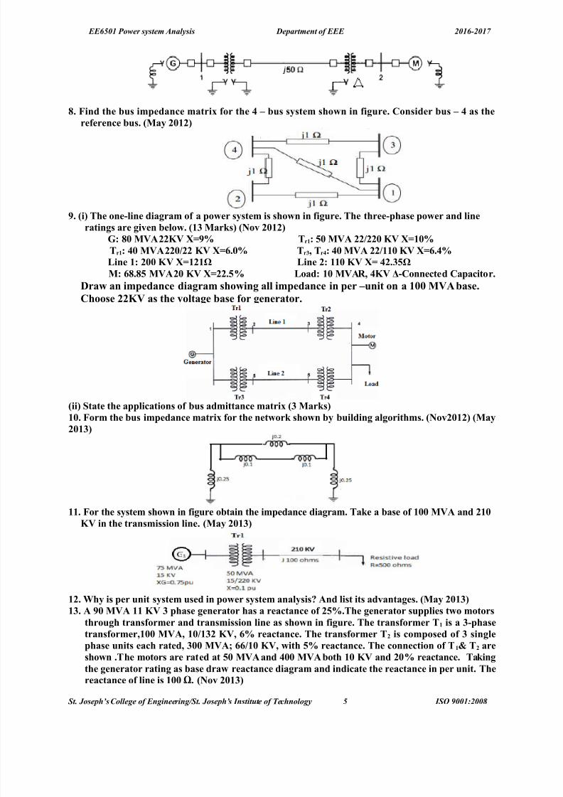
5. ind the #us impedane matri4 for the * – #us s&stem sho/n in figure. Consider #us – * as thereferene #us. +0a& ",1"
6. +i The one'$ine diagram of a po/er s&stem is sho/n in figure. The three'phase po/er and $ineratings are given #e$o/. +1% 0arJs +Nov ",1"
:B 5, 0)A ""() 69 Tr1B -, 0)A ""F"", () 1,9Tr1B *, 0)A "",F"" () .,9 Tr%8 Tr*B *, 0)A ""F11, () .*9;ine 1B ",, () 1"1L ;ine "B 11, () *".%-L
0B 5.5- 0)A ", () "".-9 ;oadB 1, 0)AR8 *() 'Conneted Capaitor.
Dra/ an impedane diagram sho/ing a$$ impedane in per –unit on a 1,, 0)A #ase.Choose ""() as the vo$tage #ase for generator.
+ii >tate the app$iations of #us admittane matri4 +% 0arJs
1,. orm the #us impedane matri4 for the net/orJ sho/n #& #ui$ding a$gorithms. +Nov",1" +0a&",1%
11. or the s&stem sho/n in figure o#tain the impedane diagram. TaJe a #ase of 1,, 0)A and "1,() in the transmission $ine. +0a& ",1%
1". Wh& is per unit s&stem used in po/er s&stem ana$&sis! And $ist its advantages. +0a& ",1%1%. A 6, 0)A 11 () % phase generator has a reatane of "-9.The generator supp$ies t/o motors
through transformer and transmission $ine as sho/n in figure. The transformer T1 is a %'phasetransformer81,, 0)A8 1,F1%" ()8 9 reatane. The transformer T" is omposed of % sing$ephase units eah rated8 %,, 0)AE F1, ()8 /ith -9 reatane. The onnetion of T 1 T" aresho/n .The motors are rated at -, 0)A and *,, 0)A #oth 1, () and ",9 reatane. TaJingthe generator rating as #ase dra/ reatane diagram and indiate the reatane in per unit. Thereatane of $ine is 1,, K. +Nov ",1%
St. Joseph’s olle!e of En!ineerin!"St. Joseph’s #nstit$te of %e&hnolo!y 5 #S' (001)200*

8/18/2019 Psa Qb 2016-2017 Questions Only
http://slidepdf.com/reader/full/psa-qb-2016-2017-questions-only 6/25
EE6501 Power system Analysis Department of EEE 2016-2017
1*. +i Determine @usfor the %'#us s&stem sho/n in figure. The $ine series impedane as fo$$o/s.
;ine +#us to #us Impedane+pu1'" ,., G H,.151'% ,.,% G H,.,6"'% ,.,5 G H,."*
Neg$et the >hunt apaitane of the $ines
+ii What are impedane and reatane diagram! 4p$ain. +Nov ",1%
1-. The >ing$e $ine diagram of a po/er s&stem is sho/n in figure a$ong /ith omponents data .Determine the ne/ per unit va$ues and dra/ the reatane diagram. Assume "- 0)A and ", ()as ne/ #ase on generator :1. +0a&8 ",1*
1. Desri#e the ?@us #ui$ding a$gorithms in detai$ed #& using a three #us s&stem. +0a& ",1*12.+iDesri#e a#out the representation of $oads. +Nov ",1*
+ii Dra/ the per unit e3uiva$ent iruit of sing$e' phase transformer!15. O#tain the per unit Impedene diagram of the Po/er s&stem of fig sho/n #e$o/B +Nov ",1*
ig one $ine diagram representation of a simp$e po/er s&stem.:enerator NoB' 1B%, 0)A8 1,.- Jv8 QQ 1. ohms:enerator NoB' "B 1- 0)A8 . Jv8 QQ 1." ohms:enerator NoB' %B"- 0)A8 . Jv8 QQ ,.- ohmsTransformer T1+% phaseB' 1- 0)A 8 %%F11 (v 8 1-." ohms per phase on high tension side .Transformer T"+% phaseB' 1- 0)A 8 %%F." (v 8 1 ohms per phase on high tension sideTransmission $ine B ",.- ohms per phase;oad A8 1-0W811()8,.6 $agging po/er fator;oad @8 *,0W8.()8,.5- $agging po/er fator.16. Using the method of #ui$ding a$gorithm find the #us impedane matri4 for the net/orJ sho/nin figure. +0a& ",1-.
St. Joseph’s olle!e of En!ineerin!"St. Joseph’s #nstit$te of %e&hnolo!y 6 #S' (001)200*

8/18/2019 Psa Qb 2016-2017 Questions Only
http://slidepdf.com/reader/full/psa-qb-2016-2017-questions-only 7/25
EE6501 Power system Analysis Department of EEE 2016-2017
16. Dra/ the reatane diagram for the po/er s&stem sho/n in figure. Neg$et resistane and use a
#ase of -,0)A and 1%.5() on generator :1. +Nov ",1-:1B ", 0)A8 1%.5 Jv8 QQ ",9:"B %, 0)A8 15., Jv8 QQ ",9:%B%, 0)A8 ", Jv8 QQ ",9Transformer T1B' "- 0)A 8 "",F1%.5 (v 8 1,9Transformer T"B' % sing$e phase unit eah rated 1, 0)A 8 1"2F15 (v 8 1,9Transformer T"B' %- 0)A 8 "",F"" (v 8 1,9
Determine the ne/ va$ues of per unit reatane of :18 T18 Transmission $ine 18 Transmission $ine "8:"8 :%8 T" and T%.",. orm #us of the test s&stem sho/n in figure using singu$ar transformation method. Theimpedane data is given in ta#$e. TaJe +1 as referene node. +Nov ",1-
$ementNo.
>e$f 0utua$@usode
Impedane @usCode
Impedane
1 1'" ,.- 1'" ,.1" 1'% ,.% %'* ,.** "'* ,.%
UNIT – II POWR ;OW ANA;>I>PART – A
1. What is po/er f$o/ stud& or $oad f$o/ stud&! +Nov ",1*The study of various methods of solution to power system networ* is referred to as load flow study. Thesolution provides the voltages at various buses, power flowing in various lines and linelosses.
". What is the need for $oad f$o/ stud&!+Nov ",1-The load flow study of a power system is essential to decide the best operation of existing system and for planning the future expansion of the system. It is also essential for designing a new power system.
%. What are the different t&pes of #uses in a po/er s&stem!The buses of a power system can be classified into three types based on the quantities being specified for the buses. The different types of buses are,!i% #oad bus or C bus !ii% enerator bus or voltage controlled bus or C" bus!iii% 8lac* bus !or% swing bus !or% reference bus
*. When the generator #us is treated as $oad #us! +Nov ",1% +0a& ",1* +Nov ",1-
St. Joseph’s olle!e of En!ineerin!"St. Joseph’s #nstit$te of %e&hnolo!y 7 #S' (001)200*

8/18/2019 Psa Qb 2016-2017 Questions Only
http://slidepdf.com/reader/full/psa-qb-2016-2017-questions-only 8/25
EE6501 Power system Analysis Department of EEE 2016-2017
>hen the generator bus is treated as load bus, the reactive power of the bus is equated to the limit it hasviolated, and the previous iteration value of bus voltage is used for calculating current iteration value.
-. What are the advantages of :'> method!i% alculations are simple so the programming tas* is less ii% the memory requirement is less iii% ?sefulfor small systems
. What are the disadvantages of :'> method!i% Jequires large number of iterations to reach convergence. ii% $ot suitable for large systems iii%onvergence time increases with siBe of the system
2. What are the advantages of N'R method!i% The $J method is faster, more reliable and the results are accurate ii% Jequires less number of iterations for convergence.iii% The number of iterations is independent of the siBe of the system.vi%8uitable for large siBe system.
5. What are the disadvantages of N'R method!i% Crogramming is more complex ii% The memory requirement is more iii% omputational time periteration is higher due to large number of calculations per iteration.
6. 7o/ the disadvantages of N'R method are overome!The disadvantages of large memory requirement can be overcome by decoupling the wea* coupling between C K and " !i.e using de coupled load flow algorithm%. The disadvantage of largecomputational time per iteration can be reduced by simplifying the decoupled load flow equations. Thesimplifications are made based on the practical operating conditions of a power system.1,. 7o/ are the diagona$ e$ements of #us Jno/n as!The diagonal elements of bus are *nown as the short circuited driving point admittance or selfadmittanceof the buses.11. >tate the maHor steps invo$ved in $oad f$o/ studies! The ma;or steps involved in load flow studies are i% +athematical modeling of the power systemL thiswould be a set of nonlinear algebraic equations. ii% 8olution of the nonlinear equations through aniterative technique.
1". Wh& ae$eration fator is used in the :'> method! To increase the rate of convergence of the iterative process, acceleration factor is used.
1%. What are the appro4imations made in D; method!i% Jeal power at a bus does not change appreciably for a small change in the voltage magnitudeii% Jeactive power at a bus does not change appreciably for a small change in bus voltage phase angle.
1*. What is the need of $oad f$o/ so$ution!The load flow solution is essential for designing a new power system and for planning extension as wellas operation of the existing one for increased power demand.
1-. What is $oad #us!( load bus is one at which the active power and reactive power are specified. In this bus its voltage can be allowed to vary within permissible values. i.e M2D. (lso bus voltages phase angle is not veryimportant for the load.
1. 7o/ the onvergene of N'R method is speeded up!The convergence of $J method is speeded up using fast decoupled load flow !=A#=% method. In =A#=,the wea* coupling between C" and K are decoupled and the equations are further simplified equationsare further simplified using the practical operating conditions of the power system.
12. What are the advantages of deoup$ed method over N'R method!
i% This method is simple and computationally efficient than the $J method.ii% It requires less memory compared to $J method.
15. What is the need for vo$tage ontro$ in a po/er s&stem!The various components of a power system !or equipments connected to power system% are designed towor* satisfactorily at rated voltages. If the equipments are not operated at rated voltages then the performance of the equipments will be poor and the life of the equipments will reduce. Hence thevoltages at various points in a power system should be maintained at rated value !specified value%
16. 7o/ the reative po/er of a generator is ontro$$ed!The reactive power of a generator is controlled by varying the magnitude and phase of induced emf,which in turn varied by varying excitation. =or an increase in reactive power the magnitude of induced
St. Joseph’s olle!e of En!ineerin!"St. Joseph’s #nstit$te of %e&hnolo!y * #S' (001)200*

8/18/2019 Psa Qb 2016-2017 Questions Only
http://slidepdf.com/reader/full/psa-qb-2016-2017-questions-only 9/25
EE6501 Power system Analysis Department of EEE 2016-2017
emf is increased and its phase angle is decreased. =or a reduction in reactive power the magnitude of induced emf is decreased and its phase angle is increased.
",. What is >$aJ or s/ing #us!+0a& ",11( bus is called swing bus when the magnitude and phase of bus voltage are specified for it. The swing bus is the reference bus for load flow solution and it is required for accounting line losses. ?sually one of the generator bus is selected as the swing bus.
"1. What is ao#ian matri4! 7o/ the e$ements of ao#ian matri4 are determined!+0a& ",11The matrix formed the first order derivatives of load flow equations is called Nacobian matrix !N%.Theelements of Nacobian matrix will change in every iteration. In each iteration the elements of this matrixare obtained by partial differentiating the load flow equations with respect to an un*nown variable andthen calculating the first derivatives using the solution of previous iteration."". What are the information that are o#tained from a po/er f$o/ stud&! +0a& ",1")us voltages, #ine transformer power flows, and transmission power losses."%. Compare :auss'seida$ and Ne/ton Raphson methods of $oad f$o/ so$utions. +0a& ",1" +Nov
",1-
>. N :auss seida$ Ne/ton Raphson1. Jeliable +ore reliable
. Jequire large number of iterations toreach convergence. It has linear convergence characteristics
=aster. Jequire less number if iteration toreach convergence It has quadraticconvergence characteristics.
&. Crogramming tas* is less Crogramming is more complex.3. 8uitable for small siBe system and not
suitable for large system. $umber iterations increases with increase in siBe.
8uitable for large siBe system. $umber of iterations does not depend on siBeof the system.
2. +emory required is less +emory required is more."*. Wh& po/er f$o/ ana$&sis is made!+Nov",1"Cower flow analysis is performed to calculate the magnitude and phase angle of voltage at the buses andalso the active power and reactive volt amperes flow for the given terminal or bus conditions. Thevariables associated with each bus or node are i% magnitude of voltage !v% ii% phase angle of voltage !K%
iii% active power !C% iv% reactive volt amperes !%."-. What is ae$eration fator!+Nov",1" +0a& ",1%The acceleration factor is a numerical multiplier which is used to increase which is used to increase therate of convergence in an iterative process. The previous value at the bus is multiplied by the accelerationfactor to obtain a correction to be added to previous values.". What is the need of s$aJ #us! +0a& ",1% +0a& ",1*The slac* bus is needed to account for transmission line losses. In a power system the total power generated will be equal to sum of power consumed by loads and losses. In a power system only thegenerated power and load power are specified for buses. The slac* bus is assumed to generate the power required for losses. 8ince the losses are un*nown the real and reactive power are not specified for slac* bus .They are estimated through the solution of load flow equations."2. Wh& do @us used in $oad f$o/ stud& instead of ?@us! +Nov ",1%
bus is sparsity matrix ie. $umber of nonBero elements is less compared to Bero elements. Henceformation of bus needs less memory."5. Define vo$tage ontro$$ed #us +Nov ",1* These are the buses where generators are connected. Therefore the power generation in such buses iscontrolled through a prime mover while the terminal voltage is controlled through the generator excitation. 'eeping the input power constant through turbinegovernor control and *eeping the busvoltage constant using automatic voltage regulator, we can specify constant P Gi and O V i |for these buses.This is why such buses are also referred to as C" buses. It is to be noted that the reactive power supplied by the generator QGi depends on the system configuration and cannot be specified in advance.=urthermore we have to find the un*nown angle δi of the bus voltage."6. Wh& is @us impedane matri4 preferred for fau$t ana$&sis! +0a& ",1-
St. Joseph’s olle!e of En!ineerin!"St. Joseph’s #nstit$te of %e&hnolo!y ( #S' (001)200*

8/18/2019 Psa Qb 2016-2017 Questions Only
http://slidepdf.com/reader/full/psa-qb-2016-2017-questions-only 10/25
EE6501 Power system Analysis Department of EEE 2016-2017
PART – @1. >tate the $oad f$o/ pro#$em and derive $oad f$o/ e3uation.". +a What are the pratia$ app$iation of the po/er f$o/ ana$&sis ! +# Derive the mathematia$ mode$ of phase shifting transformer to #e used in a po/er f$o/ana$&sis.%. The fo$$o/ing is the s&stem data for a $oad f$o/ so$utionB +Nov ",1-
The shedu$e of ative and reative po/er is
Determine the vo$tage at the end of first iteration using :'> method. TaJe ae$eration fator 1.*.*. Compare N'R and D; methods of $oad f$o/ ana$&sis.-. With neat f$o/ hart e4p$ain the omputationa$ proedure for $oad f$o/ so$ution using ast
deoup$ed method /hen the s&stem ontains a$$ the t&pes of #uses.+0a& ",11. igure sho/s a five #us s&stem. ah $ine has an impedane of +,.,-G H,.1- pu. The $ine shunt
admittane ma& #e neg$eted. The #us po/er and vo$tage speifiations are given in ta#$e.+0a& ",1"
@us P; S; P: S: ) @us >peifiation
1 1., ,.- ' ' 1.," ∠0 >$aJ #us
" , , " ' 1.," P) #us
% ,.- ,." , , ' PS @us
* ,.- ,." , , ' PS #us
- ,.- ,." , , ' PS #us
+i orm #us +ii ind S"8 "8 )%8 )*8 and )- after first iteration using :auss seida$ method.Assume S"min,."pu8 S"ma4 ,.pu.
2. What is ao#ian 0atri4! 7o/ the e$ements of ao#ian matri4 are omputed! +0a& ",1"+Nov",1"
5. Write the step #& step proedure for $oad f$o/ ana$&sis #& Ne/ton Raphson method.+0a& ",1" +Nov ",1* +0a& ",1*
6. Compare :'> and N'R methods of $oad f$o/ ana$&sis.+Nov ",1"1,. The figure given #e$o/ sho/s a po/er s&stem. +Nov ",1"
@us 1B >$aJ #us >peified1.,-,V E@us "B P) #us >peified 1." p.u P: % p.uE @us %B PS #usP; * p.u S;" p.u .Carr& out one iteration of$oad f$o/ so$ution #& :auss'>eida$ method. TaJe
S $imits of generator " as 0%Q<4 TaJeX 1.
St. Joseph’s olle!e of En!ineerin!"St. Joseph’s #nstit$te of %e&hnolo!y 10 #S' (001)200*
@us ode Admittane1'" ".,'H5.,
1'% 1.,'H%.,
"'% ,.'H".,"'* 1.,'H*.,
%'* ".,'H5.,
@us ode P S ) RemarJs1 ' ' 1.,-GH,., >$aJ
" ,.- ,." 1.,GH,., PS% ,.* ,.% 1.,GH,., PS* ,.% ,.1 1.,GH,., PS

8/18/2019 Psa Qb 2016-2017 Questions Only
http://slidepdf.com/reader/full/psa-qb-2016-2017-questions-only 11/25
EE6501 Power system Analysis Department of EEE 2016-2017
11. Consider the po/er s&stem /ith the fo$$o/ing dataB
@us No. T&pe :eneration ;oad )o$tageP S P S 0agnitude Ang$e
1 >$aJ ' ' ' ' 1., ,,
" P') -., ' , , 1.,- '% P'S , , %., ,.- ' '
@us [− 12 8 4
8 − 12 4
4 4 − 8]O#tain the po/er f$o/ so$ution +one iteration for the given s&stem . The $ine admittane are inper unit on a 1,, 0)A #ase. Use fast deoup$ed $oad f$o/ method.
1". A three #us po/er s&stem is sho/n in figure. The re$evant per unit $ine admittane on 1,, 0)A#ase are indiated on the diagram and #us data are given in ta#$e. orm@usand determine thevo$tage at #us " and #us % after first iteration using :> method. TaJe the ae$eration fator X 1. +Nov8 ",1%
@us No. T&pe :eneration ;oad )o$tage
P S P S 0agnitude Ang$e1 >$aJ ' ' ' ' 1.," ,,
" P'S "- 1- -, "- ' '% P'S , , , %, ' '
1%. +i :ive the $assifiation of various t&pes of #uses in a po/er s&stem for $oad f$o/ studies. +Nov ",1* +Nov ",1* +ii :ive the advantages and $imitations of Ne/ton Raphson method. +iiiWhat is meant #& deoup$ed $oad f$o/ method! +Nov ",1%1*. ormu$ate the po/er f$o/ e3uation for YnQ #us s&stem. +0a& ",1*1-. Desri#e the step #& step proedure for $oad f$o/ so$ution from :auss sieda$ method8 if P) and
PS #uses are present a$ong /ith s$aJ #us. +0a& ",11 +0a& ",1%8 +0a& ",1*8 +Nov ",1-1. ig. sho/n #e$o/ a three #us po/er s&stem @us 1B >$aJ #us )>peified1.,-,V E@us "B P) #us
)>peified 1., p.u 8P: % p.uE @us %B PS #us P; * p.u S;" p.u .Carr& out one iteration of $oadf$o/ so$utions #& :auss >eide$ method. Neg$et $imits on reative po/er generation! +Nov ",1*
St. Joseph’s olle!e of En!ineerin!"St. Joseph’s #nstit$te of %e&hnolo!y 11 #S' (001)200*

8/18/2019 Psa Qb 2016-2017 Questions Only
http://slidepdf.com/reader/full/psa-qb-2016-2017-questions-only 12/25
EE6501 Power system Analysis Department of EEE 2016-2017
12. In the po/er s&stem net/orJ sho/n in figure8 #us 1 is s$aJ #us /ith ) 1 1.,GH ,., pu and #us "is a $oad #us /ith >" "5,0WGH, 0)Ar. The $ine impedane on a #ase of 1,, 0)A is ?,.,"GH,.,* pu. Using :auss >eida$ method8 determine )". Use an initia$ estimate of )"
+, 1.,GH,., and perform four iterations. A$so find >1 and the rea$8 reative po/er $oss in the $ine8assuming that the #us vo$tages have onverged. +0a& ",1-
UNIT – III AU;T ANA;>I> ' @A;ANCD AU;TPART – A
1. What is >hort Ciruit 0)A and ho/ it is a$u$ated! +0a& ",1-The short circuit capacity or the short circuit +"( at a bus is defined as the product of the magnitudes of the rated bus voltage and the fault current. 8. +"( capacity of the circuit brea*er / √ & x pre faultvoltage in '" x 8. current in '(.
". What are the t&pes of fau$ts!
8:JI:8 =(?#TG a% <ne open conductor fault b% Two open conductor fault8H?$T =(?#TG !a% 8ymmetrical or balanced fault !i% Three phase =ault!###%!b% ?nsymmetrical or unbalanced fault ! i% #ine to line fault!##%!ii% #ine to ground fault !#%!iii% Aouble line to ground fault.!##%.%. What are the fators to #e onsidered for se$eting the C.@.!The factors to be considered in selecting a circuit brea*er for a protection scheme areG $ormal operatingvoltage, +omentary, interrupting current. 8peed of the brea*er and 8. interrupting +"(.*. What &ou mean #& s&mmetria$ fau$ts! +Novem#er ",1*The fault is called symmetrical fault if the fault current is equal in all the phases and the phase difference between any two phases is equal.-. What &ou mean #& dou#$ing effet!The first pea* of the resultant current will become twice the pea* value of the final steady current. This
effect is called as doubling effect.. What &ou mean #& transient and su# transient reatane!EdP !transient reactance% is the ratio of no load e.m.f and the transient symmetrical r.m.s current.EdPP !sub transient reactance% is the ratio of no load e.m.f and the sub transientsymmetricalr.m.s current.2. What is the app$iation of transient reatane!The transient and sub transient reactance helps in calculating the interrupting and maximum momentarys.c currents.5. :ive the various assumptions made for fau$t ana$&sis.The assumptions made in analysis of faults areGi% :ach synchronous machine model is represented by ane.m.f behind a series reactance ii% In the transformer models the shunt that account for core loss andmagnetiBing components are neglected.iii% In the transmission line models the shunt capacitances areneglected. iv%(ll series resistances in generators, transformers, lines are neglected. v% In the normal
operating conditions the pre fault voltage may be considered as 1.0 p.u.vi% #oad impedances areneglectedL hence the pre fault system may be treated as unloaded. vii% (s the pre fault currents are muchsmaller than the post fault currents the pre fault currents can be neglected.6. Name an& methods of reduing short iruit urrent.)y providing neutral reactances and by introducing a large value of shunt reactances between buses.1,.What are the reatanes used in the ana$&sis of s&mmetria$ fau$ts on the s&nhronous mahines
as its e3uiva$aent reatanes. i% 8ubtransient reactance Ed
Q ii% Transient Jeactance EdP iii% 8ynchronous reactance Ed
11. What is s&nhronous reatane!It is the ratio of induced emf and the steady state r.m.s current. Ed /:g IIt is the sum of lea*age reactance and the armature reaction reactances. It is given byE d / El R Ea,Ed /8ynchronous reactance. El / #ea*age reactance Ea / (rmature reaction reactance.
St. Joseph’s olle!e of En!ineerin!"St. Joseph’s #nstit$te of %e&hnolo!y 12 #S' (001)200*

8/18/2019 Psa Qb 2016-2017 Questions Only
http://slidepdf.com/reader/full/psa-qb-2016-2017-questions-only 13/25
EE6501 Power system Analysis Department of EEE 2016-2017
1".What are the auses of fau$t in po/er s&stem. +0a& ",1-( fault may occur on a power system due to a number of reasons. 8ome of the causes are!i% Insulationfailure of the system!ii% =alling of a tree along a line!iii% >ind and ice loading on the transmissionlines!iv% "ehicles colliding with supporting structures!v% <verloading of underground cables!vi% )irdsshorting the lines.1%. Name the main differenes in representation of po/er s&stem for $oad f$o/ and short iruits
studies>.N
;oad f$o/ studies >hort iruit studies
1 The resistances and reactances areconsidered
The resistances are neglected
To solve load flow analysis, the busadmittance matrix is used
To solve load flow analysis, the busimpedance matrix is used
& It is used to determine the exact voltages andcurrents
Cre fault voltages are assumed to be 1 p.uand the pre fault current can be neglected
1*. ind the fau$t urrent in figure8 if the pre fau$t vo$tage at the fau$t point is ,.62p.u!
Z t&= ( 0.15+0.2) X 0.15
( 0.15+0.2 )+0.15= 0.105 pu
=ault urrent I ' =V p'
Z t&
= 0.97
0.105= 9.238 p ( u (
1-. What is the reason for transients during short iruits!The fault or short circuits are associated with sudden change in currents. +ost of the components of the power system have inductive property which opposes any sudden change in currents and so the faults!short circuit% are associated with transients.
1. What is the signifiane of transient reatane in short iruit studies!The transient reactance is used to estimate the transient value of fault current. +ost of the circuit brea*ersopen their contacts only during this period. Therefore, for a circuit brea*er used for fault clearing, itsinterrupting short S circuit rating should be less than the transient fault current.12. What is the signifiane of su# ' transient reatane in short iruit studies!The sub transient reactance is used to estimate the initial value of fault current immediately on theoccurrence of the fault. The maximum momentary short circuit current rating of the circuit brea*er usedfor protection or fault clearing should be less than this fault clearing value.15. 7o/ to ondut fau$t ana$&sis of a po/er s&stem net/orJ!)y using equivalent circuit representation and by using bus impedance matrix16. What is meant #& fau$t a$u$ations!The fault condition of a power system can be dived into sub transient, transient and steadystate periods.
The currents in the various parts of the system and in the fault are different in these periods. Theestimation of these currents for various types of faults at variouslocations in the system are commonlyreferred as fault calculations.",. 0ention the o#Hetives of short iruit studies or fau$t ana$&sis. +0a& ",11+Nov ",1"8+Nov",1*The short circuit studies are essential in order to design or develop the protective schemes for various parts of the system. The protective scheme consists of current and voltage sensing devices, protectiverelays and circuit brea*ers. The selection or proper choice of these mainly depends on various currentsthat may flow in the fault conditions."1. Write do/n the #a$aned and un#a$aned fau$ts ourring in a po/er s&stem. +0a& ",11)(#($:A =(?#TG & phase short circuit fault?$)(#($:A =(?#TG 8ingle line to ground fault, line to line fault and double line to ground fault.
St. Joseph’s olle!e of En!ineerin!"St. Joseph’s #nstit$te of %e&hnolo!y 1+ #S' (001)200*

8/18/2019 Psa Qb 2016-2017 Questions Only
http://slidepdf.com/reader/full/psa-qb-2016-2017-questions-only 14/25
EE6501 Power system Analysis Department of EEE 2016-2017
"". Distinguish s&mmetria$ and uns&mmetria$ fau$t. +Nov ",1" +0a& ",1%The fault is called 8ymmetrical fault if the fault current is equal in all the phases.eg. & short circuit fault.ϕ
The fault is called unsymmetrical fault if the fault current is not equal in all the three phases. eg.i% singleline to ground fault ii% line to line fault iii% double line to ground fault iv% open conductor fault"%. What is meant #& fau$t $eve$! +0a& ",1%It relates to the amount of current that can be expected to flow out of a bus in to a & phase fault.=ault level in +"( at bus i=V i pu no)inal∗ I i pu'ault ∗*
3ϕbase .
"*. :ive the fre3uen& of various fau$ts ourrene in asending order+Nov ",1% +0a& ",1*T&pes of au$ts Re$ative re3uen& of Ourrene of au$ts& phase fault 2DAouble #ine to round =ault 10D#ine to #ine =ault 12D8ingle #ine to round =ault 40D
"-. Define #o$ted fau$t. +0a& ",1*( fault represents a structural networ* change equivalent with that caused by the addition of impedance at
the place of the fault. If the fault impedance is Bero, then the fault is referred as bolted or solid fault.
". or a s&stem8 the #us impedane matri4 /as found to #e ?
010.00&0.00&0.0
0&0.00T&42.00042.0
0&0.00042.00320.0
j
. The
impedanes are in pu. A three phase s&mmetria$ fau$t ours at #us % through a fau$t impedane of ?f H,.16 pu. ind out the post fau$t vo$tage at #us " assuming Zero prefau$t urrent. +0a& ",1-.
>o$utionB f kk
k
k Z Z
V F I
+=
%0!%!
4&6&.316.0010.0
01%0!%!
&&
& j j j Z Z
V F I
f
k −=
+
°∠=
+=
The post fault voltage, pu j j f I Z V T65.0&0.01%4&6&.3%!0T&42.0!01%!%0! && =−=−−°∠=−
"2. What is diret a4is reatane! +De ",1-The direct axis is defined as the direction along the rotor that the field winding current causes magnetic
flux to flow. Ed direct axis reactance.
PART – @1.A >&nhronous generator rated -,, ()A8 *,,
8 ,.1 p.u8 su# transient reatane is supp$&ing a
passive $oad of *,,(W at ,.5 $ag p.f. Ca$u$ate the initia$ s&mmetria$ R0> urrent for a % fau$tϕat the generator termina$s.
".T/o generating stations having >.C apaities of 1-,,0)A 1,,,0)A respetive$& and
operating at 11 () are $inJed #& a interonneted a#$e having s reatane of ,.
Fphase.
Determine >.C apait& of eah station.%.T/o s&nhronous motors are onneted to the #us of a $arge s&stem through a short transmission
$ine as sho/n. The ratings of the various omponents areB 0otor eahB 10)A8 **,)8 ,.1p.u
reatane. ;ineB ,.,- reatane. ;arge s&stem >.C 0)A at **,) #us is 5.,. When t/o motors
are in operation at **,)8 a$u$ate the >.C urrent +s&mmetria$ fed into a % phase fau$t at themotors.
*. A sma$$ generating station has a #us #ar divided into three setions. ah setion is onneted to atie' #ar /ith reators eah rated at -0)A8 ,.1p.u reatane. A generator of 5 0)A rating and,.1- p.u reatane is onneted to eah setion of the #us #ar. Determine the >.C apait& of the#reaJer if a % phase fau$t taJes p$ae on one of the setions of the #us #ar.
-. An a$ternator and a s&nhronous motor eah rated for -, 0)A8 1%." () having su# transient of ",9 are onneted through a transmission $inJ of reatane 1,9 on the #ase of mahine ratings.The motor ats as a $oad of %, 0W at ,.5 p.f $ead and termina$ vo$tage 1".- () /hen a % phasefau$t taJes p$ae at the motor termina$s. Determine the su# transient urrent in the a$ternator8 themotor and the fau$t.
. A >tation operating at %% () is divided into setions A @. >etion A onsists of three generators1- 0)A eah having a reatane of 1-9 and setion @ is fed from the grid through a 2- 0)A
St. Joseph’s olle!e of En!ineerin!"St. Joseph’s #nstit$te of %e&hnolo!y 1, #S' (001)200*

8/18/2019 Psa Qb 2016-2017 Questions Only
http://slidepdf.com/reader/full/psa-qb-2016-2017-questions-only 15/25
EE6501 Power system Analysis Department of EEE 2016-2017
transformer of 59 reatane. The Jt #reaJers have eah a rupturing apait& of 2-, 0)A.Determine the reatane of the reator to prevent the #reaJers #eing over $oaded if as&mmetria$ >.C ours on an outgoing feeder onneted to A
2. The per unit impedane matri4 of a four #us po/er s&stem sho/n in figure #e$o/8
?@us
[
0.15 0.075
0.075 0.1875
0.14 0.135
0.09 0.0975
0.14 0.09
0.135 0.0975
0.2533 0.21
0.21 0.2475
]Ca$u$ate the fau$t urrent for a so$id three s&mmetria$ fau$t at #us *. A$so a$u$ate the postfau$t #us vo$tages and $ine urrents.
5. 4p$ain s&mmetria$ fau$t ana$&sis using ?'#us matri4 /ith neat f$o/ hart. +0a& ",11+Nov",1"+0a& ",1%
6. A % -0)A . () a$ternator /ith a reatane of 59 is onneted to a feeder of seriesϕimpedane ,.1"GH,.*5 LF(m.The transformer is rated at % 0)A .J)F%% () and has areatane of -9.Determine the fau$t urrent supp$ied #& the generator operating under no $oad/ith a vo$tage of .6 ()8 /hen a % s&mmetria$ fau$t ours at a point 1- (m a$ong the feeder..ϕ
+0a& ",1".1,. The #us impedane matri4 of *'#us s&stem /ith va$ues in p.u is given #&8
?@us [0.15 0.08 0.040.08 0.15 0.06
0.04 0.06 0.13
0.070.09
0.05
0.07 0.09 0.05 0.12]In this s&stem generator are onneted to #uses 1 and " and their su# transient reatanesin$uded /hen finding ?@us. If pre'fau$t urrent is neg$eted8 find su# transient urrent in p.u inthe fau$t for a %'ph fau$t vo$tage as 1 p.u. If the su# transient reatane of generator in @us " is,." p.u.8 find the su# transient fau$t urrent supp$ied #& generator. +0a& ",1"
11.or the radia$ net/orJ sho/n8 a %[ 'fau$t ours at . Determine the fau$t urrent and the $inevo$tage at 11 () #us under fau$t ondition. +Nov ",1" +Nov ",1*
1". A s&nhronous generator and motor are rated %, 0)A8 1%." () and #oth have su# transientreatane of ", 9.The $ine onneting them has reatane of 1,9 on the #ase of mahine ratings.The motor is dra/ing ",8,,, (W at ,.5 p.f $eading and termina$ vo$tage of 1".5 () /hen as&mmetria$ % phase fau$t ours at the motor termina$s. ind the su# transient urrent in thegenerator8 motor and fau$t #& using interna$ vo$tages of mahines.+ 0a& ",1% +Nov ",1-
1%. A 11 ()8 1,, 0)A a$ternators having a su# –transient reatane of ,."- p.u is supp$&ing a -,0)A motor having a su# –transient reatane of ,." p.u through a transmission $ine. The $inereatane is ,.,- pu on a #ase of 1,, 0)A. 0otor is dra/ing *, 0W at ,.5 po/er fator $eading/ith a termina$ vo$tage of 1,.6- () /hen a %'phase fau$t ours at the generator termina$s.
St. Joseph’s olle!e of En!ineerin!"St. Joseph’s #nstit$te of %e&hnolo!y 15 #S' (001)200*
8/18/2019 Psa Qb 2016-2017 Questions Only
http://slidepdf.com/reader/full/psa-qb-2016-2017-questions-only 16/25
EE6501 Power system Analysis Department of EEE 2016-2017
Ca$u$ate the tota$ urrent in the generator and motor under fau$t onditions. +Nov ",1% +0a&",11.
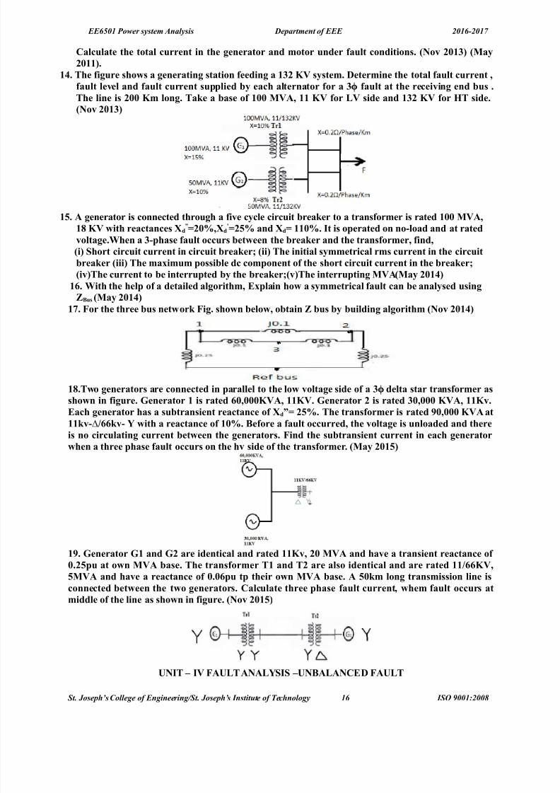
1*. The figure sho/s a generating station feeding a 1%" () s&stem. Determine the tota$ fau$t urrent 8fau$t $eve$ and fau$t urrent supp$ied #& eah a$ternator for a % fau$t at the reeiving end #us .ϕ
The $ine is ",, (m $ong. TaJe a #ase of 1,, 0)A8 11 () for ;) side and 1%" () for 7T side.+Nov ",1%
1-. A generator is onneted through a five &$e iruit #reaJer to a transformer is rated 1,, 0)A815 () /ith reatanes d
=",98dQ"-9 and d 11,9. It is operated on no'$oad and at rated
vo$tage.When a %'phase fau$t ours #et/een the #reaJer and the transformer8 find8 +i >hort iruit urrent in iruit #reaJerE +ii The initia$ s&mmetria$ rms urrent in the iruit#reaJer +iii The ma4imum possi#$e d omponent of the short iruit urrent in the #reaJerE
+ivThe urrent to #e interrupted #& the #reaJerE+vThe interrupting 0)A+0a& ",1* 1. With the he$p of a detai$ed a$gorithm8 4p$ain ho/ a s&mmetria$ fau$t an #e ana$&sed using?@us +0a& ",1*
12. or the three #us net/orJ ig. sho/n #e$o/8 o#tain ? #us #& #ui$ding a$gorithm +Nov ",1*
15.T/o generators are onneted in para$$e$ to the $o/ vo$tage side of a % de$ta star transformer asϕsho/n in figure. :enerator 1 is rated ,8,,,()A8 11(). :enerator " is rated %,8,,, ()A8 11(v.
ah generator has a su#transient reatane of d= "-9. The transformer is rated 6,8,,, ()A at11Jv'MFJv' \ /ith a reatane of 1,9. @efore a fau$t ourred8 the vo$tage is un$oaded and thereis no iru$ating urrent #et/een the generators. ind the su#transient urrent in eah generator/hen a three phase fau$t ours on the hv side of the transformer. +0a& ",1-
16. :enerator :1 and :" are identia$ and rated 11(v8 ", 0)A and have a transient reatane of ,."-pu at o/n 0)A #ase. The transformer T1 and T" are a$so identia$ and are rated 11F()8-0)A and have a reatane of ,.,pu tp their o/n 0)A #ase. A -,Jm $ong transmission $ine isonneted #et/een the t/o generators. Ca$u$ate three phase fau$t urrent8 /hem fau$t ours atmidd$e of the $ine as sho/n in figure. +Nov ",1-
UNIT – I) AU;T ANA;>I> –UN@A;ANCD AU;T
St. Joseph’s olle!e of En!ineerin!"St. Joseph’s #nstit$te of %e&hnolo!y 16 #S' (001)200*

8/18/2019 Psa Qb 2016-2017 Questions Only
http://slidepdf.com/reader/full/psa-qb-2016-2017-questions-only 17/25
EE6501 Power system Analysis Department of EEE 2016-2017
PART – A1. Name the fau$ts invo$ving ground.The faults involving ground areG single line to ground fault ii% double line to ground fault iii% Three phasefault". Define positive se3uene impedane.The negative sequence impedance of equipment is the impedance offered by the equipment to the flow of positive sequence currents.%. In /hat t&pe of fau$t the Gve se3uene omponent of urrent is e3ua$ in magnitude #ut opposite
in phase to negative se3uene omponents of urrent!#ine to line fault.*. In /hih fau$t the negative and Zero se3uene urrents are a#sent!In three phase fault the negative and Bero sequence currents are absent.-. What are the #oundar& ondition in $ine'to'$ine fau$t!
Ia/0L IaRIc/0L " b/"c
. Write do/n the #oundar& ondition in dou#$e $ine to ground fau$t!Ia/0L " b/0L "c/0
2. :ive the #oundar& ondition for the %'phase fau$t.Ia R I b / Ic/0L "a/" b/"c/0
5. Name the fau$t in /hih positive8 've and Zero se3uene omponent urrents are e3ua$.+0a& ",1"
In single line to ground fault the Rve, ve and Bero sequence component currents are equal6. Name the various uns&mmetria$ fau$ts in a po/er s&stem.i% single line to ground fault ii% line to line fault iii% double line to ground fault iv% open conductor fault1,.Write a short notes on ?ero se3uene net/orJ.>hile drawing the Bero sequence networ* of a given power system, the following points may be *ept inview.The Bero sequence currents will flow only if there is a return path i.e.path from neutral to ground or to another point in the circuit.In the case of a system with no return path for Bero sequence currents, thesecurrents cannot exist.11.Write a short notes on negative se3uene net/orJ.The negative sequence networ* can be readiley obtained from positive sequence networ* with thefollowing modificationsGi% <mit the emfs of & S phase generators and motors in the positive sequencenetwor*. It is because these devices have only positive sequence generated voltages.ii% hange, if
neccesary, the impedances between the generators neutral and ground pass no negative sequence currentand hence are not included in the negative seqeunce networ*.iii% =or static devices such as transmissionlines and transformers, the negative sequence impedances have the same value as the corresponding positive sequence impedances.1".Write a short notes on positive se3uene net/orJ.>hile drawing the positive sequence networ* of a given power system, the following points may be*ept in viewG i% :ach generator in the system is represented by the generated voltage in series withappropriate reactance and resistance. ii% urrent limiting impedances between the generators neutral andground pass no positive sequence current and hence are not included in the positive sequence networ*. Iii%(ll resistance and magnetiBing currents for each transformer are neglected as a matter of simplicity.=or transmission lines, the shunt capacitances and resistances are generally neglected.1%.7o/ /i$$ &ou e4press positive8 negative and Zero – se3uene impedanes of – onneted $oads!
Cositive seqence impedance mn s Z Z Z Z &1 ++= .$egative sequence impedance m s Z Z Z −=
@ero sequence impedance m s Z Z Z −=0
>here, @s / self impedance of S connected load, @n/ loadneutral impedance @m / +utual impedance.1*. Whih is the most fre3uent$& ourring fau$t!8ingle line to ground fault is the most frequently occurring fault1-. Define uns&mmetria$ fau$t.The fault is called unsymmetrical fault if the fault current isnot same in all the three phases.1. Whih is the most severe fau$t in po/er s&stem!Three phase fault is the most severe and rarely occurring fault in the power system.12. What is se3uene net/orJ! +0a& ",11 +Nov ",1*
St. Joseph’s olle!e of En!ineerin!"St. Joseph’s #nstit$te of %e&hnolo!y 17 #S' (001)200*

8/18/2019 Psa Qb 2016-2017 Questions Only
http://slidepdf.com/reader/full/psa-qb-2016-2017-questions-only 18/25
EE6501 Power system Analysis Department of EEE 2016-2017
The networ* which is used to represent the positive, negative and Bero sequence components of unbalanced system is called as sequence networ* 15. What are the s&mmetria$ omponents of a three phase s&stem! +0a& ",11+Nov ",1" +Nov",1* +Nov ",1-1% Cositive sequence % negative sequence &% @ero sequence16. What is meant #& a au$t! +0a& ",1"( fault in a circuit is any failure which interferes with the normal flow of current .The faults areassociated with abnormal change in current, voltage and frequency of the power system. The faults maycause damage to the equipment if it is allowed to persist for a long time.",. ;ist the various s&mmetria$ and uns&mmetria$ fau$ts in a po/er s&stem.+0a& ",1">&mmetria$ fau$tB & phase short circuit fault.Uns&mmetria$ fau$tB i% single line to ground fault ii% line to line fault iii% double line to ground faultiv% open conductor fault"1. Define negative se3uene impedane! +0a& ",1%The negative sequence impedance of an equipment is the impedance offered by the equipment to the flowof negative sequence current."". Dra/ the se3uene net/orJ onnetions orresponding to ;'; fau$t at #us. +0a& ",1%
"%. What are the o#servations made from the ana$&sis of various fau$ts! +Nov ",1%i% To chec* the +"( ratings of the existing circuit brea*ers, when new generation are added into asystemL ii% To select the rating for fuses, circuit brea*er and switch gear in addition to setting up of protective relaysL iii% To determine the magnitudes of currents flowing throughout the power system atvarious time intervals after a fault occurs."*. Write the #oundar& onditions for sing$e $ine to ground fau$t. +Nov ",1%The boundary conditions are "a / 0L I b/Ic/0
"-. What are the features of Zero se3uene urrent! +0a& ",1*(s Bero sequence currents in three phases are equal and of same phase, three systems operate li*e single phase as regards Bero sequence currents. @ero sequence currents flow only if return path is availablethrough which circuit is completed.". Write the s&mmetria$ omponent urrent of phase YaQ in terms of % urrents. +0a& ",1*.ϕ
I a0=
1
3[ I a+ I b+ I c ] I a1
=1
3[ I a+aI b+a
2 I c ] I a2
=1
3[ I a+a
2 I b+a I c ]
"2. Derive the e4pression for neutra$ grounding reatane suh that the sing$e $ine to ground fau$turrent is $ess than the three phase fau$t urrent. +0a& ",1-.
"5. >tate the reason /h&8 the negative se3uene impedane of a transmission $ine is taJen as e3ua$
to positive se3uene impedane of the $ine. +0a& ",1-.
"6. What is se3uene Operator! +Nov ",1-In balanced problem, to find the relationship between phase voltagesand phase currents, we use sequence
operator. (n operator which will turn a phasor through 10 degree in three phase problems. This operator iscalled as U a U operator.
PART – @1. A generator of neg$igi#$e resistane having 1., per vo$tage #ehind transient reatane is su#Heted
to different t&pes of fau$tsT&pe of fau$t Resu$ting fau$t urrent in p.u%'phase %.%%
St. Joseph’s olle!e of En!ineerin!"St. Joseph’s #nstit$te of %e&hnolo!y 1* #S' (001)200*

8/18/2019 Psa Qb 2016-2017 Questions Only
http://slidepdf.com/reader/full/psa-qb-2016-2017-questions-only 19/25
EE6501 Power system Analysis Department of EEE 2016-2017
;'; "."%;': %.,1
Ca$u$ate the per unit va$ue of % se3uene reataneQs.". A -,7Z 5,0)A8 11J) generator has positive8 negative and Zero se3uene impedanes of H,.*8 H,.%
and H,.1p.u respetive$&. The generator is onneted to a #us#ar A through a transformer1",H,.*p.u.on 1,,0)A #ase and rated vo$tage. Determine the ohmi resistane and ratingof earthing resistor suh that for ;: fau$t on #us#ar @8 the fau$t urrent of the generator does note4eed fu$$ $oad urrent. A reator of reatane ,.,5p.u on 1,, 0)A #ase is onneted #et/een#us #ars A and @.
%. Deve$op the e4pressions for ana$&Zing dou#$e $ine to ground fau$t in a $arge po/er s&stem using?#us matri4.
*. A -,7Z8 1%." ()8 1-0)A a$ternator has 1"",9 and ,59 and the neutra$ is groundedthrough a reator of ,.-ohm. Determine the initia$ s&mmetria$ rms urrent in the groundreator /hen a dou#$e $ine to ground fau$t ours at the generator termina$s at a time /hen thegenerator vo$tage /as 1"().
-. Derive the neessar& e3uations for a$u$ating the fau$t urrent and #us vo$tages for a sing$e $ineto ground fau$t.
. A %'phase8 1, 0)A8 11()8 generator /ith so$idit& earthed neutra$ point supp$ies a feeder. There$evant impedanes of the generator and feeder in ohm are as #e$o/B
:enerator eeder+a Gve se3uene H1." H1.,+# 've se3uene H,.5 H1.,+ Zero se3uene H,.* H%.,
If the $ine to $ine fau$t ours at the far end of the feeder8 a$u$ate the fau$t urrent.2. A sa$ient po$e generator is rated ", 0)A8 1%.5 J) and has 1,."-p.u ",.%-p.u and
,,.1p.u. The neutra$ of the generator is so$id$& grounded. Compute fau$t urrent in thegenerator and $ine to $ine to ground fau$t at its termina$s. Neg$et initia$ $oad on the generator.The reatane of a generator are QQ",.1-p.u and ,,.,-p.u. The generator ratings are 1,0)A8 (). The generator is star onneted /ith neutra$ point grounded through a reator of ,.-ohm reatane. Compute fau$t urrent in amps /hen a sing$e $ine to ground fau$t ours atthe generator termina$s.
5. T/o "- 0)A8 11() s&nhronous generators are onneted to a ommon #us #ar /hih supp$ies
a feeder. The star point one of the generators is grounded through a resistane of 1 ohm andthat of the other generator is iso$ate. A $ine to ground fau$t ours at the far end of the feeder.Determine the fau$t urrent.
6. Deve$op the e4pressions for ana$&Zing sing$e $ine to ground fau$t in a $arge po/er s&stem using?#us matri4.
11.What are the assumptions made in short iruit studies! Dedue and sho/ the se3uene net/orJ for a $ine to $ine fau$t at the termina$s of a un$oaded generator. +0a& ",11
1". T/o 11()8 ",0)A .Three phase star onneted generators operate in para$$e$ as sho/n infigure. The positive8 negative and Zero se3uene reatane are H,.158H,.1-8H,.1, pu. The starpoint of one of the generator is iso$ated and that of the other is earthed through "., ohmsresistor. A sing$e $ine to ground fau$t ours at the termina$s of one of the generators. stimate iau$t urrent iiurrent in the grounding resistor and iiithe vo$tage aross the grounding
resistor. +0a& ",11
1%. Derive the neessar& e3uation to determine the fau$t urrent for a sing$e $ine to ground fau$t.Dra/ a diagram sho/ing the interonnetions of se3uene net/orJs. +0a& ",1"
1*. A11 J)8 %,0)A a$ternator has ?1?"'H,." pu and ?,'H,.,- pu. A $ine to ground fau$t ourson the generator termina$s. Determine the fau$t urrent and $ine to $ine vo$tages during fau$ted
St. Joseph’s olle!e of En!ineerin!"St. Joseph’s #nstit$te of %e&hnolo!y 1( #S' (001)200*

8/18/2019 Psa Qb 2016-2017 Questions Only
http://slidepdf.com/reader/full/psa-qb-2016-2017-questions-only 20/25
EE6501 Power system Analysis Department of EEE 2016-2017
onditions. Assume that the generator neutra$ is so$id$& grounded and the generator is operatingat no $oad and at the rated vo$tage during the ourrene of the fau$t. +0a& ",1"
1-. A -, 0)A 11 () a$ternators /as su#Heted to different t&pes of fau$ts. The fau$ts are % fau$tϕ152,A8 ;ine to ;ine au$t "-6,A8 >ing$e $ine to ground fau$t *1%, A. The a$ternator neutra$ isso$id$& grounded. ind the per unit va$ues of the three se3uene reatane of an a$ternator. +0a&",1".
1. Dra/ the se3uene net/orJ onnetion for a dou#$e $ine to ground fau$t at an& point in a po/ers&stem and from that o#tain an e4pression for the fau$t urrent. +Nov ",1"
12. Derive an e4pression for the tota$ po/er in a three phase s&stem in terms of se3ueneomponents of vo$tages and urrents. +ii Disuss in detai$ a#out the se3uene impedanes of transmission $ines. +Nov ",1" +Nov ",1-
15. Disuss in detai$ a#out the se3uene impedanes and net/orJs of s&nhronous mahines8transmission $ines8 transformers and $oad. +0a& ",1%
16. A sing$e $ine diagram of a po/er net/orJ is sho/n in the figure. +0a& ",1%
The s&stem data is given in the ta#$es #e$o/B
$ement Positive se3uenereatane
Negative se3uenereatane
?ero se3uenereatane
:enerator : ,.1 ,.1" ,.,-0otor 01 ,.,- ,., ,.,"-
0otor 0" ,.,- ,., ,.,"-TransformerTr1
,.,2 ,.,2 ,.,2
TransformerTr"
,.,5 ,.,5 ,.,5
;ine ,.1, ,.1, ,.1,
:enerator grounding reatane is ,.- pu. Dra/ se3uene net/orJs and a$u$ate the fau$t for a$ine to $ine fau$t on phase # and at point P. Assume 1., pu pre fau$t vo$tage throughout.
",. The figure sho/s the po/er s&stem net/orJ .Dra/ Zero se3uene net/orJ for this s&stem. Thes&stem data is as under.:enerator :1B-, 0)A 811 ()8 , ,.,5 pu Transformer T1 B-, 0)A811F"", ()8 , ,.1pu:enerator :" B%, 0)A 811 ()8 , ,.,2pu Transformer T" E%, 0)A 811F"", () 8, ,.,6 pu?ero se3uene reatane of $ine is ---. K. Choose #ase 0)A -, and #ase vo$tage 11 () for ;Tside and "", () for 7T side. +Nov ",1%
"1. A "- 0)A 8 1%." () a$ternator /ith so$id$& grounded neutra$ has a su# transient reatane of ,."- p.u. The negative and Zero se3uene reatane are ,.%- and ,.,1 p.u. respetive$&. If adou#$e $ine'to'ground fau$t ours at the termina$s of the a$ternator8 determine the fau$t urrentand $ine to $ine vo$tage at the fau$t. +0a& ",1*
"". O#tain the e4pression for fau$t urrent for a $ine to $ine fau$t taJen p$ae through an impedane?# in a po/er s&stem.+Nov ",1%+0a& ",1*
"%. 4p$ain a#out the onepts of s&mmetria$ omponent. +Nov ",1*"*. A sing$e $ine to ground fau$t ours on @us 1 of the s&stem of the fig. sho/n #e$o/.indi Current in the fau$tii >C urrent in phase A of generatoriii )o$tage of the hea$th& phases of the #us1 using ? #us method
St. Joseph’s olle!e of En!ineerin!"St. Joseph’s #nstit$te of %e&hnolo!y 20 #S' (001)200*

8/18/2019 Psa Qb 2016-2017 Questions Only
http://slidepdf.com/reader/full/psa-qb-2016-2017-questions-only 21/25
EE6501 Power system Analysis Department of EEE 2016-2017
:ivenB Rating of the eah mahine 1",,()A8 ,,)8/ith "1,98o-9 eah three phasetransformer is rated 1",, ()A 8 ,,)'MF%,,,)' /ith $eaJage reatane of -9 the reatane of the transmission $ine are 1 " ",9 and o*,9 on the #ase of 1",, ()A 8%%,,)8the
reatane of the neutra$ reators are -9 on the ()A and vo$tage #ase of the mahine. +Nov",1*
"-. Ca$u$ate the su#' transient urrent in eah phase for a dead short iruit on one phaseto ground at #us Y3Q for the s&stem sho/n in figure.
". A %, 0)A8 11(v8 % s&nhronous generator has a diret su#transient reatane of ,."- pu. Theϕnegative and Zero se3uene reatane are ,.%- and ,.1pu respetive$&. The neutra$ of thegenerator is so$id$& grounded. Determine the su#transient urrent in the generator and the $ineto $ine vo$tages for su#transient onditions /hen a sing$e $ine to ground fau$t ours at thegenerator termina$s /ith the generstor operating un$oaded at rated vo$tages. +Nov ",1-
UNIT–) >TA@I;ITANA;>I>PART – A
1. Define D&nami sta#i$it& of a po/er s&stem.Aynamic stability is the stability given to an inherently unstable system by automatic control devices andthis dynamic stability is concerned with small disturbances lasting for times of the order of 10 to &0seconds.
". Define the inertia onstants 0 7.(ngular momentum !+% about a fixed axis is defined as the product of moment of inertia about that axisand the associated angular velocity. + / I. ω wattrad8ec.Inertia constant !H% is the '.: in +ega ;oulesto the three phase +"( rating of the machine.%. Define $oad ang$e of a generator.#oad angleG This is the angle between the generated e.m.f or the supply voltage !: % and the terminalvoltage. This angle is also called as torque or power angle of the machine.*. >tate e3ua$ area riterion of sta#i$it&.
The system is stable if the area under accelerating power !Ca% δ curve reduces to Bero at some value of δ.In other words positive area under Ca δ curve must be equal to the negative area and hence the nameequal area criterion of stability.-. What are $imitations of e3ua$ area riterion!
The limitations of equal area criterion areG i% one drawbac* of equal area criterion approach is that criticalclearing time cannot be calculated even though the critical clearing angle is *nown. Hence numericalmethods such as Junge*utta method, point by point or :ulerPs method are employed.ii% ItPs a more simplified approach.. If t/o mahines /ith inertiaQs 7 18 7" are s/inging together8 /hat /i$$ #e the inertia of the
e3uiva$ent mahine!
! s= !
1+
1+ !
2+
2
+s
H1 and H is the Inertia constant of +1 and +L 1 and is the capacity of +1 and +.Hs is the equivalent inertia of +1 and + L s is the equivalent capacity of +1 and +.2. On /hat #asis do &ou on$ude that the given s&nhronous mahine has $ost sta#i$it&!
St. Joseph’s olle!e of En!ineerin!"St. Joseph’s #nstit$te of %e&hnolo!y 21 #S' (001)200*
8/18/2019 Psa Qb 2016-2017 Questions Only
http://slidepdf.com/reader/full/psa-qb-2016-2017-questions-only 22/25
EE6501 Power system Analysis Department of EEE 2016-2017
=ollowing a sudden disturbance on a power system rotor speeds, rotor angular differences and power transfer undergo fast changes whose magnitude is dependent on the severity of the disturbance. If thesedisturbances leads to growing oscillations in the power system even after some period of time say morethan &0 seconds then system said are in asynchronous state and it has lost synchronism.5. On /hat a fator does the ritia$ $earing ang$e depends.The critical clearing angle depends upon the clearing time, which depends upon auto closingreclosingand opening of circuit brea*ers.6. Define stead& state sta#i$it& $imit. +Nov ",1*
It is the maximum power that can be transferred without the system becoming unstable when the systemis sub;ected to small disturbances.1,. 0ention methods of improving the stead& state sta#i$it& $imit.Cmax / ! :." E %. The steady state stability limit can be increased by i% Jeducing the E, in case of transmission lines by using double circuit lines. ii% ?se of series capacitors to get better voltage. iii%Higher excitation systems and quic* excitation system are employed.11. A -,7Z8 * po$e tur#o a$ternator rated at ", 0)A8 1%." () has as inertia onstant 7 * (W –
seF ()A. ind the (. stored in the rotor at s&nhronous speed.= / 20HB. C / 3, / 0 +"(, H / 3 '> S 8ec '"(. 8tored '.: / 3 x 0 / 50+N.1". 0ention the methods used for the so$ution of s/ing e3uation.+ethods used for solution of swing equation areG Coint by point method, +odified :ulerPs method andJunge*utta method.1%. :ive methods used for improving the transient sta#i$it&.The following methods are employed to increase the transient stability limit of the power system!i%Increase of system voltages,!ii% use of ("J.!iii%?se of High speed excitation systems.!iv%Jeduction intransfer reactance.!v%?seof high speed reclosing brea*ers.1*. Define the term s&nhroniZing po/er oeffiient of a s&nhronous mahine!
The rate!dpdδ%, ie, the differential power increase obtained per differential load angle increase is calledthe synchroniBing power coefficient or electrical stiffness of a synchronous machine.1-. What are the app$iations of e3ua$ area riterion!!i% 8witching operation. !ii% =ault and subsequent circuit isolation. !iii% =ault, circuit isolation andreclosing1. What are the $assifiations of ang$e sta#i$it&!8mall signal stability !steady state% and transient stability !large signal%.8mall signal is further classifiedas <scillatory and $on oscillatory stability.<scillatory includes Inter area mode, control mode andTorsional mode12. Define ritia$ $earing ang$e and time! +0a& ",11+0a& ",1"+Nov ",1" +Nov ",1* +0a&",1-
ritical clearing angle Vδc Pcorresponds to critical clearing timetc,in which the fault in the line is cleared by the circuit brea*er above which the system goes out of synchronism.15. Write s/ing e3uation +0a& ",11
CmCe/ +dKdt. Cm Input +echanical powerG Ce S output electrical powerL + (ngular momentum16. Define transient sta#i$it& and sta#i$it& $imit. +0a& ",1"The maximum power that can be transferred through the system during a very large disturbance withoutloss of synchronism is called transient stability limit.
",. Distinguish #et/een stead& state and transient state sta#i$it&. +Nov ",1"8teady state stability is basically concerned with the ability of the system to restore bac* to its stable stateupon a small disturbance whereas the transient stability is concerned with large disturbances."1. What is meant #& po/er ang$e urve! +0a& ",1% +Nov ",1-The graphical plot of real power versus powertorque angle is called as power angle curve.
Ce / Cm sin δ. Cm / :1: E."". Define Infinite #us in po/er s&stem. +Nov ",1"+0a& ",1%The capacity of a system comprising of many machines is so large, that its voltage W frequency may be ta*en as constant. The connection or disconnection of a single machine does not change the O"O andfrequency. 8uch a constant voltage and frequency system is called as Infinite bus."%. Differentiate #et/een vo$tage sta#i$it& and rotor ang$e sta#i$it&. +Nov ",1%
St. Joseph’s olle!e of En!ineerin!"St. Joseph’s #nstit$te of %e&hnolo!y 22 #S' (001)200*

8/18/2019 Psa Qb 2016-2017 Questions Only
http://slidepdf.com/reader/full/psa-qb-2016-2017-questions-only 23/25
EE6501 Power system Analysis Department of EEE 2016-2017
"oltage stability is the ability of a power system to maintain steady acceptable voltage at all buses in thesystem under normal operating conditions and after being sub;ected to a disturbance.Jotor angle stability is the ability of interconnected synchronous machines of a power system to remainin synchronism."*. Define s/ing urve! What is the use of this urve! +Nov ",1%
( graph of δ versus time in seconds is called swing curve. The stability of the machine is calculated byusing swing curve. This curve is obtained by solving the swing equation of the machine. The critical angle
and critical clearing time is calculated by using swing curve."-. Define d&nami sta#i$it& +0a& ",1*The dynamic stability study is concerned with the study of nature of oscillations and its decay for smalldisturbances.". ind the fre3uen& of osi$$ation for a s&nhroniZing o'effiient of ,.8 inertia onstant 7 *
and s&stem fre3uen& of -, 7Z. +0a& ",1*
=requency of oscillation / √
M L M =
!
-' =
4
- X 50=0.0255 p ( u
=requency of oscillation / √ 0.6
0.0255=4.85
rad
sec=
4.85
2 - =0.7719 !.
"2. A four po$e 8 , 7Z s&nhronous generator has a rating of ",, 0)A8 ,.5 po/er fator $agging.The moment of inertia of the motor is *-81,,Jg'm". Determine 0 and 7. +Nov ",1->o$ution.
Ns p
f 10
15,,rpm8ns NsF, %, rps8 ]s "^ ns 155.*
(ineti nerg&
1 s J ω
MJ J x x T.465465T4T003.15532000
1 ==
Inertia Constant 7 MVA MJ
G
KE .66.&
00
T.465==
0
ree Electricl MJ
x xf
KE
xf
G! degsec04&63T.0
T0150
T.465
150150
===
"5. 7o/ is the po/er s&stem sta#i$it& $assified! +0a& ",1-
PART @
1. A -,7Z generator is supp$&ing ,9 of Pma4 to an infinite #us through a reative net/orJ. A fau$t
ours /hih inreases the reataneQs of the net/orJ #et/een the generator interna$ vo$tageand infinite #us #& *,,9. When the fau$t is $eared8 ompute the ma4 va$ue of ritia$ $earingang$e #& app$&ing e3ua$ area riteria.
". >tate the #ad effets of insta#i$it&. Distinguish #et/een stead& state and transient state sta#i$ities.%. T/o po/er stations A @ are $oated $ose together. >tation A has * identia$ generator sets eah
rated 1,,0)A and having an inertia onstant of 6 0 F 0)A8 /hereas station @ has three sets
St. Joseph’s olle!e of En!ineerin!"St. Joseph’s #nstit$te of %e&hnolo!y 2+ #S' (001)200*

8/18/2019 Psa Qb 2016-2017 Questions Only
http://slidepdf.com/reader/full/psa-qb-2016-2017-questions-only 24/25
EE6501 Power system Analysis Department of EEE 2016-2017
eah rated ",,0)A 8 * 0F 0)A. Ca$u$ate the inertia onstant of sing$e e3uiva$ent mahineson a #ase of 1,, 0)A.
*. 4p$ain the u$erQs method of so$ving the sta#i$it& pro#$em.-. A -, 7Z * po$e tur#o a$ternator rated ", 0)A8 1%." () has an inertia onstant of 7 6(W'
seF()A. Determine the (. stored in the rotor at s&n speed. Determine the ae$eration if theinput is $ess8 the rotationa$ $osses is ",,,, 7P and e$etri po/er de$ivered is 1-,,,(W. If theae$eration omputed for the generator is onstant for a period of 1- &$es8 Determine thehange in tor3ue ang$e in that period and the r.p.m at the end of 1- &$es. Assume that thegenerator is s&nhroniZed /ith a $arge s&stem and has no ae$erating tor3ue /hen 1- &$eperiod #egins.
. A motor is reeiving %,9 of the po/er that it is apa#$e of reeiving from an infinite #us. If the
$oad on the motor is dou#$ed. Ca$u$ate the ma4 va$ue ofδ
during the s/inging of the rotor
around its ne/ e3ui$i#rium position. +Nov ",1-.2. Desri#e the Runge'(utta method of so$ution of s/ing e3uation for mu$ti mahine s&stems.
+0a& ",115. Derive the Po/er ang$e e3uation for a i >0I@ s&stem and a$so dra/ the po/er ang$e urve.
+0a& ",1" What are the tehni3ues avai$a#$e to improve stead& state sta#i$it&! +0a& ",1-ii A generator having d,.2pu de$ivers po/er at po/er fator of ,.5 ;agging. DeterminePe8Se8 and .
6. Using 3ua$ area riterion derive an e4pression for ritia$ $earing ang$e for a s&stem having agenerator feeding a $arge s&stem through a dou#$e iruit $ine. +0a& ",1" +Nov ",1*
1,. A % phase generator de$ivers1., pu po/er to an infinite #us through a transmission net/orJ /hen fau$t ours. The ma4imum po/er /hih an #e transferred during pre'fau$t8 during fau$tand post fau$t ondition are 1.2-pu8 ,.*pu and 1."- pu. ind the ritia$ $earing ang$e. +0a&",1"
11. +a >tate and e4p$ain the e3ua$ area riterion. +# Indiate ho/ &ou /i$$ app$& e3ua$ areariterion.+i To find the ma4 additiona$ $oad that an #e sudden$& added. +ii In a t/o iruittransmission s&stem sudden $oss of one iruit. +Nov ",1" +0a& ",1%
1". Derive the s/ing e3uation of a s&nhronous mahine s/inging against an infinite #us. C$ear$&state the assumptions made in deduing the s/ing e3uation. >tate the usefu$ness of thise3uation. >tate the reasons for its non$inearit& and e4tend the derivation for t/o para$$e$onneted oherent and inoherent mahines.+0a& ",1* +0a& ",1% +Nov ",1* +Nov ",1-.
1%. +iDistinguish #et/een stead& state8 transient and d&nami sta#i$it&. +Nov ",1%1*. +i 4p$ain the methods of improving po/er s&stem sta#i$it&. +Nov ",1% +ii 4p$ain the terms ritia$ $earing ang$e and ritia$ $earing time in onnetion /ith the
transient sta#i$it& of a po/er s&stem. +0a& ",11 1-. Desri#e the a$gorithm for modified u$er method of finding so$ution for po/er s&stem sta#i$it&
pro#$em studies.+Nov ",1" +0a& ",1*.1. A , 7Z s&nhronous generator has a transient reatane of ,." per unit and an inertia onstant
of -. 0F0)A. The generator is onneted to an infinite #us through a transformer and adou#$e iruit transmission $ine8 as sho/n in the figure. Resistanes are neg$eted andreatanes are e4pressed on a ommon 0)A #ase and are marJed on the diagram. Thegenerator is de$ivering a rea$ po/er of ,.22 per unit to #us #ar 1. )o$tage magnitude at #us 1 is
1.1pu. The infinite #us vo$tage ) 1., pu0∠
. Determine the generator e4itation vo$tage ando#tain the s/ing e3uation.
12. The moment of inertia of a * po$e8 1,, 0)A8 11(v8 % 8 ,.5 po/er fator8 -, 7Z tur#o a$ternatorϕis 1,,,,Jg'm". Ca$u$ate 7 and 0. +Nov ",1-.
St. Joseph’s olle!e of En!ineerin!"St. Joseph’s #nstit$te of %e&hnolo!y 2, #S' (001)200*

8/18/2019 Psa Qb 2016-2017 Questions Only
http://slidepdf.com/reader/full/psa-qb-2016-2017-questions-only 25/25
EE6501 Power system Analysis Department of EEE 2016-2017


![ebbY^TY^TY]Qb[Udc · ebbY^TY^TY]Qb[Udc \UhQ^TbQ Qb[Ud Y^W\Q[Ub_TeSU5 bdYcQ^ Qb[Ud dQWWUbdi·cUQc_^c]Qb[Ud iQbS[S_e^dbi]Qb[Ud _\\iWe]!_]]e^Ydi Qb[Ud \_gUbTQ\U!_]]e^Ydi]Qb[Ud QbicfY\\U](https://img.pdfslide.net/doc/110x75/5f05f5a57e708231d41595c8/ebbytytyqbudc-ebbytytyqbudc-uhqtbq-qbud-ywqubtesu5-bdycq-qbud-dqwwubdicuqccqbud.jpg)