Embed Size (px)
Citation preview

PSO
Process Sign -Off Edition 5.5

COPYRIGHT 2007 DAIMLERCHRYSLER CORPORATION

COPYRIGHT 2007 DAIMLERCHRYSLER CORPORATION
Edition 5.5
December 2006
PROCESS SIGN-OFF (PSO)

COPYRIGHT 2007 DAIMLERCHRYSLER CORPORATION
INTENTIONALLY LEFT BLANK

COPYRIGHT 2007 DAIMLERCHRYSLER CORPORATION
Process Sign-Off (PSO)
FOREWARD TO THE 5.5 EDITION
This manual shall define the requirements for Process Sign-Off (PSO) and detail the documentation required to verify conformance to DaimlerChrysler's (DCC) Quality System Standards. The PSO, ISO/TS-16949 and Chrysler Development System (CDS) will form the foundation for Supplier readiness to assure proactive Advanced Product Quality Planning. A Supplier’s certification to ISO/TS-16949 alone is not sufficient for PSO approval; all PSO requirements must be met in order to assure conformance to dimensional, material, functional and (where necessary) appearance requirements. In addition, it should be noted that every external Supplier of production parts to DaimlerChrysler Corporation shall be ISO/TS-16949:2002 third party registered. Effective 01/01/2007, all requirements stated in this document apply to all DaimlerChrysler Production Suppliers, including sub-tier Suppliers. In order to achieve an appreciable improvement in part quality, this manual has been modified to reflect DaimlerChrysler Corporation’s current PSO philosophy. Emphasis is placed on the importance of adhering to our Product Creation Process, i.e. the Chrysler Development System (CDS). This manual should be reviewed carefully and in its entirety to assure that all PSO requirements are known and understood. The 25 PSO Process Elements identified in the 5th Edition PSO Manual were re-evaluated and, in some cases, modified or removed. The name “DaimlerChrysler” and “DCC”, as used in this manual, refer to DaimlerChrysler Corporation (i.e., DCC formerly known as Chrysler Corporation) and its subsidiaries, which manufacture Chrysler, Dodge and Jeep® brand vehicles. This manual does not apply to other DaimlerChrysler AG subsidiaries or operations, which manufacture Mercedes-Benz, Freightliner or other brand vehicles or products. Where the word “Supplier” is used in this manual, it is intended to indicate both external and internal Tier 1 Suppliers. Where the term “DCC PSO Team” is utilized, it denotes DaimlerChrysler Employee involvement only. The term “PSO team” indicates all individuals involved in the PSO process (i.e., DCC and Supplier). For questions or comments concerning the Process Sign-Off manual, please contact your DaimlerChrysler Advance Supplier Quality Planning Specialist (ASQP Specialist).

COPYRIGHT 2007 DAIMLERCHRYSLER CORPORATION
ACKNOWLEDGMENTS
PROCESS SIGN-OFF (PSO)
Edition 5.5
Process Sign-Off 5.5 Revision Team Members
David Eller Mgr - AQP Strategy & Processes
Bryan Book AQP Strategy & Processes
Nance Taylor AQP Strategy & Processes
Vic Randolph AQP Strategy & Processes
Eric Helgeson ASQP - BIW/Exterior
Larry D'Agostino ASQP - Chassis
Simon Kissonergis ASQP - Electrical/Electronics
Cris Miller ASQP - Interior
Neil Murphy ASQP - Powertrain
Ida Goodwill CDS
Dennis Fett Corporate Quality
Chris Cottam Manufacturing Quality
Lynn Yang Powertrain Quality
Mary Clor Process Quality Engineering
Arno Reiter Supplier Quality - Graz
Dave Koski ASQP - AQP/PSO University
Hector Magaña Supplier Quality - Mexico
Requests for revisions or changes to the manual should be directed to the PSO 5.5 Revision Team

COPYRIGHT 2007 DAIMLERCHRYSLER CORPORATION
PROCESS SIGN-OFF (PSO)
Table of Contents Page Introduction ............................................................................................................ 1 Process Sign-Off Flow Chart & Responsibilities ......................................................... 6 Process Sign-Off Element Requirements.................................................................. 11 Appendix A Forms and Instructions ......................................................................... 45 Appendix B Tables and Examples ........................................................................... 61 Appendix C FTC Calculations .................................................................................. 67 Appendix D PSO Extended Run ............................................................................... 79 Appendix E Forever Requirements ........................................................................... 81 Appendix F Internal PSO Requirements .................................................................... 87 Frequently Asked Questions .................................................................................... 93 Reference Manuals................................................................................................. 98 Glossary ................................................................................................................ 99 Index................................................................................................................... 111

COPYRIGHT 2007 DAIMLERCHRYSLER CORPORATION
INTENTIONALLY LEFT BLANK

COPYRIGHT 2007 DAIMLERCHRYSLER CORPORATION 1
Process Sign-Off (PSO)
INTRODUCTION SCOPE: Process Sign-Off (PSO) shall be performed on all new or modified parts with
PPAP requirements or parts that have been out of production for 12 months or longer. Additional conditions that may result in a PSO being required are: � Carry-over parts with historically high warranty and/or quality
problems; � Carry-over parts which have experienced a Supplier responsible yard
hold within the past calendar year; � New and/or additional production lines (e.g. capacity increases); � Production line moves, within a year of PSO approval;����� Any product or process change that occurs during the lifecycle of a part
or system.
PROCESS SIGN-OFF DEFINITION WHAT IS A PSO? Process Sign-Off is a formal review of the Supplier's production
manufacturing process. This process verifies a Supplier’s ability to manufacture production material at the daily tool capacity (as noted on the Production Purchase Order or as provided in writing by the DCC Production Buyer).
Each PSO includes evaluation of associated production facilities, related manpower, equipment, material, methods, procedures, software level(s) and tooling. The PSO is utilized to scrutinize the Supplier’s entire production process, including all in-house and secondary systems that support primary production line(s).
The DaimlerChrysler PSO is composed of three primary activities: 1. Pre-PSO Meeting
The DCC PSO Team shall review PSO documentation during AQP meetings and again during the Pre-PSO Meeting for compliance to PSO requirements.
2. PSO On-site Visit
The DCC PSO team shall witness at least one Production Demonstration Run (PDR) utilizing completed production tools as part of the PSO process for all Collaborative and Directed AQP Activity Level parts. PSO activities shall be conducted by the Supplier for all Self-Directed AQP Activity Level parts. Data collection, analysis, and summarization are the true measures of part quality and production capabilities. Observing the PDR should reveal issues such as bottlenecks and inefficiencies. Production Process review and measurements will provide the production rate, First Time Capability (FTC) and other statistics that validate each Supplier’s ability to effectively produce both the required quality and product quantities.

COPYRIGHT 2007 DAIMLERCHRYSLER CORPORATION 2
Full compliance with all PSO requirements and procedures ensures that the Supplier’s manufacturing process is stable, in control and capable of producing parts that meet all requirements.
3. Validation Testing
Production Validation (PV) Testing, of the Production Demonstration parts, will validate the Supplier’s system and provide evidence that the parts meet engineering, quality, durability, and reliability requirements contained in the Performance, Process, and Material Specifications.
Packaging and shipping or simulation test approvals are required by Material Handling Engineering if applicable.
WHY IS A PSO NECESSARY? Process Sign-Off is an effective method of verifying a Supplier’s quality
planning processes. It confirms that the processes can and will (when properly and successfully executed) produce quality parts in sufficient quantities for production.
WHO CONDUCTS THE PSO?
The PSO Team consists of, at a minimum, the DCC ASQP Specialist, DCC Product Engineer and Supplier(s) Representatives. � Other PSO team members may include but are not limited to; the DCC
Buyer, Center of Competence (COC) Engineer, and Vehicle Specialist. � The DCC ASQP Specialist has lead responsibility for the PSO for parts or
modules with Collaborative and Directed AQP Activity Levels. � The Supplier has lead responsibility for parts with Self-Directed AQP
Activity Levels. � The Supplier shall identify Supplier PSO team members for both the
DaimlerChrysler led PSO’s, as well as for Supplier led Self-Directed PSO’s. WHEN IS THE PSO PERFORMED?
The Process Sign-Off, On-Site Visit shall be scheduled by the PSO Team following the Pre-PSO Documentation Review, when the PSO Team agrees that: � All required Supplier documentation has been reviewed and is acceptable; � Production tooling is complete, on-site at the Supplier's Plant, setup,
debugged and the Supplier Readiness Evaluation (SRE) performed; � SRE is complete and the results have been documented and are
acceptable to the team; and � The production operators are trained and capable of running at the
required line speed. The purpose of the PSO is to demonstrate Supplier process capability and production capacity. The PSO demonstration shall produce dimensionally correct parts on the home-line with production tooling. The requirement is to complete all PSO’s and PPAP submissions prior to supplying parts for S1 Start. If PPAP is not complete prior to S1

COPYRIGHT 2007 DAIMLERCHRYSLER CORPORATION 3
Start, an Interim Approval Authorization (IAA) is required. For specific requirements regarding IAA submission, refer to P&S procedure PSSP0108 as well as any special requirements of the specific DCC Product Team. Suppliers do not have access to this procedure and should contact their DCC ASQP Specialist or Engineer for additional information regarding IAAs. HOW IS THE PSO PERFORMED? Refer to Figure 1 for the PSO strategy and Figures 2.1 and 2.2 for a step-by-
step flowchart and responsibility matrix for the PSO process. �� Pre-PSO Meeting:
The DCC ASQP Specialist will initiate PSO dialogue with the DCC Product Engineer and the Supplier (i.e., for Directed and Collaborative PSO’s). Together, they will schedule and coordinate the Pre-PSO Meeting as well as the PSO On-Site Visit. The ASQP Specialist will advise the Supplier of the documentation the team will want to review and whether the part has been selected for a PSO Extended Run.
�� Process Sign-Off On-Site Visit:
The PSO Team shall complete the first 20 elements of the PSO SUMMARY REPORT at the Supplier’s manufacturing facility. The PSO Team shall also verify the Supplier’s compliance to all 21 elements of PSO Edition 5.5 before full approval is given. Any deviations shall be recorded on the PSO COMMENTS SHEET. A successful PDR shall yield parts for Production Validation (PV) Testing.
When appearance approvals are required, the Supplier shall obtain a signed Appearance Approval Report (AAR) prior to PPAP submission. Refer to the AIAG PPAP manual and DCC Engineering Standards CS-9022 and PS-4559 for further guidance. PSO “Z” Approval: “Z” Approval is an internal code within the Powerway.com system. This code, in conjunction with the submission of a dimensional Part Submission Warrant (PSW), indicates that the first 20 PSO elements have been completed and approved. At this point, the Supplier may be eligible for partial tooling payment (for further tool payment information, reference the source package and the DCC Purchasing contact noted there in). The ASQP Specialist is responsible for entering the “Z” approval into Powerway.com for Directed and Collaborative AQP Activity Level parts. The Supplier is responsible for entering the “Z” approval into Powerway.com for Self-Directed AQP Activity Level parts. “Z” approval authorizes the Supplier to submit the Dimensional Part Submission Warrant (PSW) into Powerway.com. PSO “A” Approval: The “A” Approval is an internal code within Powerway.com. This code, in conjunction with the submission of a material and/or functional PSW (and an AAR, if required) confirms that all PSO and PPAP requirements have been met. The Supplier is then eligible for full tooling payment. The ASQP Specialist is responsible for entering the “A” approval into Powerway.com for Directed and Collaborative AQP Activity Level parts. The Supplier is responsible for entering the “A” approval into Powerway.com for Self-Directed AQP Activity Level parts.

COPYRIGHT 2007 DAIMLERCHRYSLER CORPORATION 4
The PSO date and an “A” disposition are required to be entered into Powerway.com prior to the Supplier submitting the Warrant (PSW) and entering the PPAP date and PPAP “A” disposition. This requirement is true for all parts, regardless of AQP Activity Level. PSO “N” Approval: The “N” disposition is an internal code within Powerway.com. This code indicates that the PSO On-Site Visit was unsuccessful and corrective action is required by the Supplier. A new PSO planned visit date (or corrective action completion date) is required to be entered into Powerway.com. Interim Approval Authorization All parts require full PSO and PPAP approval. PSO “A” approval is a prerequisite for PPAP approval. PPAP approvals are submitted through Powerway.com by the Supplier. Failure to submit PPAP before S1 Start will require an Interim Approval Authorization (IAA). Reference the internal DCC procedure PSSP0108. Suppliers do not have access to this procedure and should contact their DCC ASQP Specialist or Engineer for additional information regarding IAAs. NOTE 1: Even with “Z” Approval, an IAA is still required. NOTE 2: Any deviations to the PSO requirements outlined in this manual must be requested and approved in writing by the DCC ASQP Specialist and Product Engineer, REGARDLESS OF AQP ACTIVITY LEVEL. Approval(s) must be obtained from DCC before completion of the PSO process. Requested deviation(s) shall be formally outlined in detail within the COMMENT SHEET of the completed PSO.
�

COPYRIGHT 2007 DAIMLERCHRYSLER CORPORATION 5
CONDUCT PRE-PSO MEETING (REVIEW
SUPPLIER’S DOCUMENTATION & SRE)
PSO TEAM CONDUCTS PSO ON-SITE VISIT or SUPPLIER PERFORMS
PRODUCTION DEMONSTRATION RUN
(Self Directed AQP)
SUPPLIER CONDUCTS PV TESTING
PSO TEAM COMPLETES
PROCESS SIGN-OFF
SUPPLIER SUBMITS PPAP PART SUBMISSION
WARRANT
PROCESS SIGN – OFF STRATEGY
REVIEW PSO REQUIREMENTS WITH
PSO TEAM & SUPPLIER
SUPPLIER PERFORMS READINESS EVALUATION
RUN
SUPPLIER COMPLIES WITH CONTINUOUS
CONFORMANCE REQUIREMENTS

COPYRIGHT 2007 DAIMLERCHRYSLER CORPORATION 6
1 PART ENTERS
POWERWAY.COM
2 INITIAL RISK EVALUATION & AQP LEVEL
PROCESS SIGN-OFF FLOWCHART
3 SUPPLIER LED PSO
4 DAIMLERCHRYSLER
LED PSO
3A SUPPLIER
UPLOADS DOCUMENTS INTO POWERWAY.COM
5 PSO REQUIREMENTS
REVIEW WITH PSO TEAM AND
SUPPLIER
Self Directed AQP Collaborative/Directed AQP
6 SUPPLIER PREPARES DOCUMENTATION AND CONDUCTS READINESS
EVALUATION RUN
7 PRE-PSO MEETING:
DOCUMENTATION/SRE ACCEPTABLE?
9 SCHEDULE
PSO ON SITE VISIT
10 SUPPLIER FINALIZES LINE AND APPROVES EVIDENCE OF PRO-
DUCTION READINESS
a c
YES
NO
d
Figure 2.1
8 SUPPLIER MODIFIES
AND SUBMITS DOCUMENTATION
AND/OR CONDUCTS READINESS
EVALUATION RUN
b

COPYRIGHT 2007 DAIMLERCHRYSLER CORPORATION 7
PROCESS SIGN-OFF
FLOWCHART RESPONSIBILITIES
RESPONSIBILITY LEGEND PROCESS NAME
DC
C
PR
OC
UR
EM
EN
T
DC
C
EN
GIN
EE
RIN
G
DC
C
MA
NU
FA
CTU
RIN
G
DC
C
AS
QP
SU
PPLIE
R
REMARK L = LEAD RESPONSIBILITY
1 Part enters Powerway.com
L P
S = SUPPORT TO 2 Initial Risk P S L S P = PROVIDES INFORMATION
3& 3(A)
Supplier led PSO P S P S L
P/S = DEPENDS ON COMPOSITION OF
4 DaimlerChrysler led PSO
P S P L S
PSO TEAM 5
PSO Requirements Review
P S P L S
6 Supplier prepares documentation and readiness evaluation
P S P S L
7 Pre-PSO Documentation Reviews
P/S
S P/S
L S
8 Supplier modifies and submits documentation
P S P S L
9 Schedule PSO On-Site Visit
P S P L S
10 Supplier finalizes line and approves evidence production
P S P S L

COPYRIGHT 2007 DAIMLERCHRYSLER CORPORATION 8
11 PSO ON-SITE VISIT or SUPPLIER CONDUCTS
PRODUCTION DEMONSTRATION RUN
12 ELEMENTS 1-20 ACCEPTABLE?
A
YES
NO
c
NO
19 PSO APPROVED,
“A” DISPOSITION AND COMPLETION DATE
ENTERED IN POWERWAY.COM
YES
d
NO
Figure 2.2
b
17 INVESTIGATE REASON
FOR FAILURE AND ROOT CAUSE ELIMINATION
15 SUPPLIER CONDUCTS
ELEMENT 21
16 ELEMENT 21
ACCEPTABLE?
20 SUPPLIER SUBMITS
PPAP WARRANT & ENTERS PPAP DATE IN
POWERWAY.COM
12A PSO ON-SITE REVISIT
NECESSARY?
13 SUPPLIER CONDUCTS CORRECTIVE ACTION
AND SUBMITS DOCUMENTATION
NO
18 REPETITION
OF ELEMENT 21 SUFFICIENT?
YES
YES
14 “Z” DISPOSITION AND COMPLETION DATE
ENTERED IN POWERWAY.COM
19A SUPPLIER CONDUCTS PSO IN ACCORDANCE
WITH PSO MANUAL AND ENTERS PSO
DATE & DISPOSITION INTO POWERWAY.COM

COPYRIGHT 2007 DAIMLERCHRYSLER CORPORATION 9
PROCESS SIGN-OFF FLOWCHART RESPONSIBILITIES
RESPONSIBILITY LEGEND PROCESS NAME
DC
C
PR
OC
UR
EM
EN
T
DC
C
EN
GIN
EE
RIN
G
DC
C
MA
NU
FA
CTU
RIN
G
DC
C
AS
QP
SU
PPLIE
R
REMARK
11 PSO On-Site Visit P/S
S P/S L S
L = LEAD RESPONSIBILITY S = SUPPORT TO
12 &12(A)
Acceptance of Elements 1-20
P/S
S P/S L P
P = PROVIDES INFORMATION P/S = DEPENDS ON COMPOSITION OF PSO TEAM
13
Supplier conducts corrective action and submits documentation. ASQP provides approval
P S P L L
14
"Z" code entered into Powerway.com. Supplier enters Dimensional PPAP & date
S L P
15 Supplier conducts
Element 21 P S P S L
16 Acceptance of Element
21 P/S
S P/S L P
17
Investigate reason for failure and root cause elimination
P S P S L
18 Repetition of Element 21 P/
S S P/S S L
19
PSO "A" disposition & date entered into Powerway.com. Supplier enters Material/ Functional PPAP & date
P/S
S P/S L P
19A
Supplier conducts PSO and enters “A” disposition & date into Powerway.com
P/S
S P/S S L
20 Supplier submits PPAP warrant and date into Powerway.com
P S P S L
Refer to PPAP
Manual for further details
�

COPYRIGHT 2007 DAIMLERCHRYSLER CORPORATION 10
INTENTIONALLY LEFT BLANK

COPYRIGHT 2007 DAIMLERCHRYSLER CORPORATION 11
PSO ELEMENT REQUIREMENTS

COPYRIGHT 2007 DAIMLERCHRYSLER CORPORATION 12
PART NUMBER, DESCRIPTION AND CHANGE LEVEL Element Requirements Documentation
1.1 The PSO team shall review all PSO related documents to ensure all documents have the correct part number, description and change level present or cross-referenced (see ISO/TS-16949 cl. 4.2.3 Control of Documents). 1.2 A procedure shall be in place to assure correct part number and revision level as changes occur. This procedure shall also ensure affected documents (e.g. Control Plan, PFMEA, etc.) are updated and applicable testing is performed for each change.
1.2.1 This procedure shall include communication and notification of changes throughout the Supply Chain. The Tier 1 Supplier is ultimately responsible to ensure product shipped to DCC (or other designated manufacturing facility) is the latest revision level. 1.2.2 This procedure shall include the receipt of an approved DCC Change Notice. The Supplier shall not make any changes without DOCUMENT approval from the customer (voicemail, e-mail, etc. are UNACCEPTABLE).
1.3 Where the product identity is not inherently obvious, the Supplier shall employ an internal numbering system and provide a cross reference which enables users to identify the DCC part number and revision level which corresponds to the Supplier’s numbering and revision system. 1.4 The Supplier shall have a procedure which prevents non-standardized or out of date documents and instructions from existing on the manufacturing floor (e.g. Document audit). Refer to ISO/TS-16949, cl. 4.2.3 Control of Documents. Engineering Standards Identified 1.5 A process shall be in place to obtain revisions to all DCC, governmental, Safety <S>, and other product related standards and specifications. DCC standards are available via Engineering Standards Supplier Distribution (ESSD) at https://essd.extra.daimlerchrysler.com/ESSD/Login.jsp.
1.5.1 This process shall address notification to all applicable departments of standard changes as they occur. This process shall also include the frequency and responsibility for reviewing the standards (not to exceed two working weeks; reference ISO/TS-16949, cl. 4.2.3.1 Engineering Specifications.)
1.6 The PSO Team shall verify that the CATIA Comment page or Part Information Page (PIP) lists all applicable standards, including, but not limited to, those shown on the source package and signed DVP&R (see Element 3 “Test Sample Sizes and Frequencies”.)
1.6.1 DCC approval for all deviations from listed standards shall be documented on the CATIA Comment page/PIP and DVP&R.
� CATIA files, drawings, Comment page, Part Information Pages (PIP) (including list of applicable engineering standards, software level and hardware level) (MANDATORY ENGLISH)
� Gage Dimensioning & Tolerancing (GD&T) sheets (MANDATORY ENGLISH)
� Part number cross reference sheet (if applicable)
� Engineering Change procedure
� Document Control procedure

COPYRIGHT 2007 DAIMLERCHRYSLER CORPORATION 13
PART NUMBER, DESCRIPTION AND CHANGE LEVEL, CONT. Element Requirements
1.6.2 The PSO Team shall verify that the CATIA Comment page or PIP lists all sub-components of the end-item assembly. This listing shall include DCC part number (if applicable), Supplier part number, quantity, and revision level.
1.6.3 The PSO Team shall verify that all dimensional requirements are defined on the GD&T sheets and attached to the design model. The Supplier shall consistently apply a mutually agreed upon (with the DCC PSO Team) datum scheme throughout the part development process.

COPYRIGHT 2007 DAIMLERCHRYSLER CORPORATION 14
DESIGN FMEA Element Requirements Documentation
2.1 Design FMEAs (DFMEAs) shall be created using the latest AIAG and DCC guidelines. If AIAG and DCC guidelines disagree, DCC guidelines take precedence. 2.2 The Supplier shall have an internal “best practice” procedure that is utilized in the development of DFMEAs. The procedure shall include documentation and data which explains how the DFMEA severity, occurrence, and detection numbers were developed.
2.2.1 This procedure shall be reviewed periodically for effectiveness and shall include lessons learned with inputs from past issues (e.g. eCIMS, NCT, warranty, CSA, yard holds, etc.)
2.2.2 The procedure shall include use of the “Rolling Top 20” rule for continuous improvement. This requires the Supplier to Pareto failure modes and address the top 20% using RPN values (regardless of actual RPN value.)
2.3 Error proofing and controls shall be identified in the DFMEA. 2.4 The DFMEA is a living document and shall be traceable to all design changes. It shall contain all special characteristics from Element 12 “Special Product/Process Characteristics Identified”. 2.5 A DFMEA shall be completed for each unique Supplier-designed product. The DCC Product Engineer has the lead responsibility for ensuring that the DFMEA meets all requirements. Additionally, timely completion and approval of all DFMEA activities shall be completed on or before required quality gate timing. Reference the CDS Quality Gate Book at http://roadmap.tcc.chrysler.com/cds/ for specific timing. 2.6 The DFMEA shall include all sub-components of the end-item assembly. 2.7 The Supplier shall ensure all failures observed during Engineering Development (ED) and Design Verification (DV) testing are captured within the DFMEA. 2.8 The Supplier shall ensure the occurrence and detection ability of failures observed during DV testing correlate with the occurrence and detection numbers documented on the DFMEA. 2.9 Buzz-Squeak-Rattle (BSR) and Noise-Vibration-Harshness (NVH) issues shall be addressed, if applicable. NOTE: Special attention (as defined by DCC Engineering) shall be given to failure modes with:
� A Severity � 8, regardless of Occurrence or Detection values. � A Severity � 5 and Occurrence � 2, regardless of Detection (this
equates to customer dissatisfaction and c’s/1000 > 1.) � A Detection of 10.
See Appendix B “FMEA Guidelines”.
� DFMEA (MANDATORY ENGLISH)
� “Best Practice” procedure

COPYRIGHT 2007 DAIMLERCHRYSLER CORPORATION 15
TEST SAMPLE SIZES AND FREQUENCIES Element Requirements Documentation
3.1 Products covered under a Performance Standard (PF) that specifies test sample sizes, test frequencies, and acceptance criteria shall have testing requirements included in a Design Verification Plan and Report (DVP&R), including a “Test to Failure” verification plan. Reference the Product Assurance Testing manual. 3.2 Design Verification (DV) and Production Validation (PV) test plans shall be signed by the DCC Product Engineer PRIOR to testing. 3.3 Completed DV and PV test results shall be signed by the DCC Product Engineer. 3.4 All functional requirements shall be defined in the DVP&R and verified against applicable Performance Standards for accuracy.
3.4.1 Deviations from the Performance Standards shall be identified and visible on the CATIA Comment page or PIP and DVP&R (e.g. changes to test sample sizes, test waivers, etc.) See Element 1 “Part Number, Description, and Change Level.”
3.4.2 Continuous Conformance testing shall be documented on the DVP&R when applicable.
3.4.3 A "circle grid analysis", or other formability analysis, is required for PSO approval on stamped components if required by the DCC ASQP Specialist and/or Engineer.
3.4.4 DCC internal stamped components shall follow the requirements in MQAS 90-6710 “Dimensional Buy-Off Procedure for Upgrading Stamped Parts During Die/Tool Development.”
3.5 All testing failures shall be documented on the DVP&R and addressed with a DCC 8-Step Corrective Action plan (available on the “Forever Requirements” webpage and through COVISINT). 3.6 Annual validation testing shall be completed each model year as specified in the Product Assurance Testing manual and applicable Performance Standards, unless waived in writing by the DCC Product Engineer and ASQP Specialist. Reference ISO/TS-16949, cl. 7.5.2. NOTE: A written waiver is required each model year that annual validation will not be performed.
3.6.1 The Supplier shall have a procedure to ensure on-time Annual Validation, prevent scheduling conflicts and fixture/testing shortages in the event of multiple Annual Validations.
� DCC Engineering signed DVP&R (MANDATORY ENGLISH)
� Applicable Engineering Standards (MANDATORY ENGLISH)
� DCC Engineering signed DV and PV test plans (MANDATORY ENGLISH)
� Annual Validation procedure

COPYRIGHT 2007 DAIMLERCHRYSLER CORPORATION 16
PROCESS FMEA Element Requirements Documentation
4.1 Process FMEAs (PFMEAs) shall be created using the latest AIAG and DCC guidelines. If AIAG and DCC guidelines disagree, DCC guidelines take precedence. 4.2 The Supplier shall have an internal “best practice” procedure that is utilized in the development of PFMEAs. The process shall include documentation and data which explains how the PFMEA severity, occurrence, and detection numbers were developed.
4.2.1 This procedure shall be reviewed periodically for effectiveness and shall include lessons learned with inputs from past issues (e.g. eCIMS, NCT, warranty, CSA, yard holds, etc.).
4.2.2 The procedure shall include use of the “Rolling Top 20” rule for continuous improvement. This requires the Supplier to Pareto failure modes and address the top 20% using RPN values (regardless of actual RPN value.)
4.3 Mistake proofing and controls shall be identified in the PFMEA. 4.4 The PFMEA is a living document and shall be traceable to all process changes. It shall contain all special characteristics from Element 12 “Special Product/Process Characteristics Identified”. 4.5 The DCC ASQP Specialist has the lead responsibility for ensuring that the PFMEA meets all requirements (“green”) per the “Supplier PFMEA Audit Summary” sheet. Also, timely completion and approval of all PFMEA activities shall be completed on or before required quality gate timing. Reference the CDS Quality Gate Book at http://roadmap.tcc.chrysler.com/cds/for specific gate deliverables. 4.6 The PFMEA shall reflect the entire manufacturing process from receiving through shipping. 4.7 The Supplier shall ensure that all failure modes observed during all pre-production runs are captured on the PFMEA.
4.7.1 The Supplier shall ensure the rate of occurrence and ability to detect failures observed during pre-production runs correlate with occurrence and detection numbers documented on the FMEA.
4.8 BSR and NVH issues shall be addressed if applicable. NOTE: Special attention shall be given to failure modes with:
� A Severity � 8, regardless of Occurrence or Detection values. � A Severity � 5 and Occurrence � 2, regardless of Detection value
(this equates to customer dissatisfaction and c’s/1000 > 1.) � A Detection of 10.
See Appendix B and the “Supplier PFMEA Audit Summary” sheet (internal DCC work instruction PSWI-1047; Suppliers do not have access and should obtain a copy from their ASQP Specialist.)
� PFMEA (MANDATORY ENGLISH)
� PFMEA Audit Summary (MANDATORY ENGLISH)
� “Best Practice” procedure

COPYRIGHT 2007 DAIMLERCHRYSLER CORPORATION 17
PROCESS FLOW DIAGRAM AND MANUFACTURING FLOOR PLAN Element Requirements Documentation
5.1 The process flow diagram shall represent the entire manufacturing process from receiving through shipping operations, including main-line assembly processes as well as all off-line supply processes.
5.1.1 The process flow diagram shall include the processing sequence, method and equipment used at each station (including inspection and repair/rework stations). 5.1.2 Stations which measure special characteristics and/or contribute to significant customer issues shall be identified.
5.2 The manufacturing floor plan shall show the layout of the facility and the station-by-station flow of the manufacturing process.
5.2.1 The manufacturing floor plan shall highlight all production equipment used. 5.2.2 The manufacturing floor plan shall show Work in Process (WIP), raw material, and scrap material storage locations. 5.2.3 A work station layout shall exist which identifies all work stations.
5.3 The flow diagram, manufacturing floor plan and/or the work station layout shall include each unique machine number. 5.4 The flow diagram, manufacturing floor plan and/or the work station layout shall include the number of operators, including float operators, required per station (including repair/rework stations). The PSO team shall verify the number of operators during the On-Site Visit. 5.5 The flow diagram, manufacturing floor plan and/or the work station layout shall identify bottleneck operations or stations. 5.6 All production equipment appearing on the manufacturing floor plan, flow diagram, and work station layout shall be verified by the PSO team.
� Process flow diagram (or equivalent) (MANDATORY ENGLISH)
� Manufacturing floor plan
� Work Station Layout

COPYRIGHT 2007 DAIMLERCHRYSLER CORPORATION 18
CONTROL PLAN & PROCESS MONITORING Element Requirements Documentation
6.1 The Control Plan shall describe each step of the manufacturing process including: receiving, material handling and storage, in- process operations, testing, inspections, rework/repair, shipping, temporary or interim off-standard operations (e.g. back-up operations), and continuous conformance. Refer to the AIAG Advanced Product Quality Planning manual.
6.1.1 Measurement and inspection frequencies detailed in the Control Plan, including all inspections for appearance requirements, shall be verified by the PSO Team during the Production Demonstration Run. 6.1.2 Repair/rework stations shall have controls equivalent to those of the primary production line.
6.1.3 The Control Plan shall address verification of Mistake Proofing (e.g. number of pieces, frequency, etc.). 6.1.4 The Supplier shall have a process which links the Supplier’s DFMEA and PFMEA to the Control Plan. This process shall ensure that controls, lessons learned, etc. detailed in the DFMEA and PFMEA, are carried forward into the Control Plan. 6.1.5 The Supplier shall reference known issues from similar products (e.g., e-CIMS, warranty, NCTs, yard holds) and include any applicable preventive actions in the Control Plan. 6.1.6 All process and product control parameters and tolerances shall be documented in the Control Plan.
6.1.7 All special characteristics identified in the GD&T sheets and the DVP&R and any special characteristics that describe materials, processes, performance, reliability, quality, and/or design requirements identified in the DFMEA and PFMEA shall be included in the Control Plan.
6.1.8 Sample sizes shall be based on industry-standard statistical sampling plan tables or shall use Statistical Process Control (SPC).
Process Monitoring 6.2 The Supplier is responsible for maintaining manufacturing process capability and shall have a procedure requiring documented corrective actions for all out of control measurements. All reaction plans shall include containment of suspected non-conforming product and 100% inspection as approved by the PSO Team. 6.3 A documented First Piece Approval procedure shall exist which verifies product at each station is being made according to specification, proper machine set-up, and correct parameter setting.
� Control Plan (MANDATORY ENGLISH)
� 1st piece approval procedure & records
� Control Charts � Process Performance � Log Sheets � Defect Tracking Sheets

COPYRIGHT 2007 DAIMLERCHRYSLER CORPORATION 19
CONTROL PLAN & PROCESS MONITORING, CONT. Element Requirements
6.3.1 The procedure shall require First Piece Approval at the beginning of each shift or production run and after any changes are made to the production process (e.g. tooling modifications, SPC adjustments, etc.) 6.3.2 The process shall include the retention of the first piece until the end of the production run or shift and identification of the first piece sample(s) and analysis of special characteristics identified by the PSO Team and the Supplier during the AQP process.
6.3.3 Documented evidence of First Piece Approval process execution shall be maintained. The Supplier shall record the part number, manufacturing date, and any additional information as required by the PSO Team.
6.4 All inspection stations shall have a method of defect tracking (e.g., tally sheets, scrap sheets, etc.) 6.5 Visual displays of process performance (e.g. FTC, scrap and rework) and total production maintenance (e.g. downtime, etc) shall be present on the manufacturing floor and reflect current quality data.
6.5.1 Targets shall be identified for each measurable with documented plans for achieving those targets.
6.6 Where SPC methods are used, the Supplier is required to maintain a history of component production sequence, production line, production tool and characteristics’ values to assist in assembly plant, warranty and field return root cause investigations. See the “DaimlerChrysler Customer-Specific Requirements” for ISO/TS-16949, cl. 4.1.1. 6.7 Suppliers shall have a Craftsmanship Quality Initiative Procedure for all components with appearance requirements. This procedure shall include: team members, regular scheduled Craftsmanship reviews and audits, condition resolution tracking matrix, retention of an Appearance Manual, and containment procedures and guidelines.
6.7.1 Suppliers shall have an Appearance Manual for all components with appearance requirements. This manual shall include: appropriate documentation (sign-off sheet, table of contents, revision history, general appearance characteristics acceptance specification), studio quality photos of product shown in appropriate views, studio quality photos for any “conditions” deviating from design intent, and all Craftsmanship worksheets (photos of conditions, containment and permanent correction actions, along with supporting documentation.)

COPYRIGHT 2007 DAIMLERCHRYSLER CORPORATION 20
QUALITY PLANNING Element Requirements Documentation
7.1 All Advance Product Quality Plans (APQPs) shall coordinate with DCC Chrysler Development System (CDS) timing for each applicable program. The plan shall identify major milestone events, required product or process deliverables, responsible organizations, as well as scheduled and actual timing dates. Reference the AIAG Advanced Product Quality Planning and Control Plan (APQP) manual and CDS at http://roadmap.tcc.chrysler.com/cds/. Supply Base Management 7.2 The Supplier shall cascade quality planning throughout all sub-tiers (see cl.7.4.3 of ISO/TS-16949, Quality Management Systems).
7.2.1 The plan shall include an “Easy Map” diagram. This diagram should outline the entire Supply Chain, beginning with raw materials and ending with the DCC or the DCC-designated manufacturing facility. All secondary processes and/or services (e.g. plating, heat treating, etc.) shall be shown, including off-site storage or shipping locations. “Easy Map” can be found on the COVISINT website.
7.2.2 Each component listed on the Bill of Material corresponding to the DCC part number shall have an Initial Risk Evaluation (or equivalent) performed. The criteria for risking components shall take into consideration the DCC risk drivers. DCC risk drivers are found on the Initial Risk Evaluation document in Powerway.com.
7.2.2.1 Each sub-component determined to be “medium” or “high” risk (or equivalent) shall be accompanied by a PSO (or equivalent process) conducted by the Supplier. Level 3 PPAP documentation is also required. Additional documentation may be requested by the DCC ASQP Specialist. 7.2.3 The Supplier shall have a process which monitors and documents the quality of all sub-tiers.
Problem Solving 7.3 The Supplier shall have a procedure to convey lessons learned and corrective actions back through their facility, and all other facilities within the same company. (Reference ISO/TS-16949, cl. 8.5.2.1 Problem Solving.)
7.3.1 Corrective action shall be implemented across the entire manufacturing plant for every applicable DCC production line.
7.4 The acceptable methods for documenting root cause analyses and corrective actions (for all non-conformances, test failures, etc.) are through the DCC eCIMS system and/or the 8-Step Corrective Action form.
� AQP or APQP timeline/plan
� List with PPAP status of all sub-components.
� “Easy Map” Supply Chain diagram
� Listed risk of all sub-components and sub-tier processes.
� Level 3 PPAP documentation for all sub-components and sub-tier processes risked medium or high.
� DOE (Design of Experiments)
� Copies of eCIMS or 8-Step Corrective Actions for issues encountered in previous pilot builds.
� Lessons Learned Communication procedure

COPYRIGHT 2007 DAIMLERCHRYSLER CORPORATION 21
QUALITY PLANNING, CONT. Element Requirements
7.5 The PSO team shall review corrective actions for any non-conformances or test failures encountered prior to the PSO visit (e.g. during pilot builds, DV testing, etc.) The team shall ensure that all corrective actions have been completed and implemented (e.g. through error and/or mistake proofing, process or design changes, etc.) 7.6 The Supplier shall have a procedure for conducting Design of Experiments (DOE). DOE (or similar activities) shall be conducted to identify and establish the optimal process parameters for all new and modified parts prior to the PSO On-Site Visit. 7.7 The Supplier shall support all DCC systems (e.g. eCIMS, Non-Conformance Ticket (NCT) system, Powerway.com, PRAS, COVISINT, etc.) NOTE: For source packages that reflect proprietary document exclusions, those documents sited for exclusion are not required to be uploaded into Powerway.com. However, these documents shall be available for review at the request of the DCC ASQP Specialist. A cover page with the documents title block, revision level and date is required to be uploaded in place of the actual document.
7.7.1 The Supplier shall have at least 2 individuals with valid SIDs and passwords for each applicable DCC eSystem (e.g. Powerway.com, Non-Conformance Ticket system, eCIMS, COVISINT, PRAS, etc.) All individuals shall be fully trained in the use of each system for which they access.
7.8 The Supplier shall provide both a Plant and Warranty Quality Representative, as required, to assist DCC personnel throughout the life of the program.
7.8.1 Contact names shall be provided by the Supplier upon request. Additional contact information may be obtained by DCC personnel (only) through the ODIMS system via the p12 screen.
7.8.2 When the Supplier is a DCC directed sub-tier, the Supplier Representative(s) shall support the Tier 1 in the same manner as they would DCC. Support is to begin at Gate G1 Theme Selection and continue though the life of the program.
7.9 Design responsible Suppliers are responsible for Design for Serviceability, which ensures ease of disassembly of product with minimal cost and time.
COPYRIGHT 2007 DAIMLERCHRYSLER CORPORATION 22
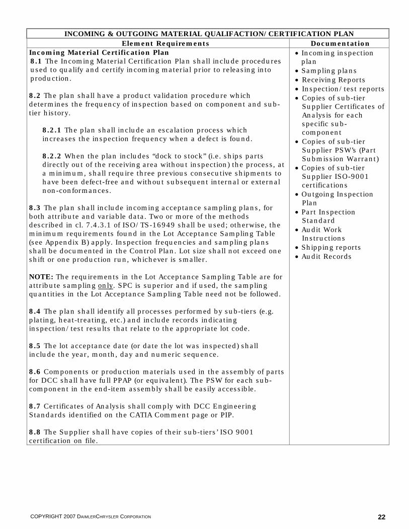
INCOMING & OUTGOING MATERIAL QUALIFACTION/CERTIFICATION PLAN Element Requirements Documentation
Incoming Material Certification Plan 8.1 The Incoming Material Certification Plan shall include procedures used to qualify and certify incoming material prior to releasing into production. 8.2 The plan shall have a product validation procedure which determines the frequency of inspection based on component and sub-tier history.
8.2.1 The plan shall include an escalation process which increases the inspection frequency when a defect is found.
8.2.2 When the plan includes “dock to stock” (i.e. ships parts directly out of the receiving area without inspection) the process, at a minimum, shall require three previous consecutive shipments to have been defect-free and without subsequent internal or external non-conformances.
8.3 The plan shall include incoming acceptance sampling plans, for both attribute and variable data. Two or more of the methods described in cl. 7.4.3.1 of ISO/TS-16949 shall be used; otherwise, the minimum requirements found in the Lot Acceptance Sampling Table (see Appendix B) apply. Inspection frequencies and sampling plans shall be documented in the Control Plan. Lot size shall not exceed one shift or one production run, whichever is smaller. NOTE: The requirements in the Lot Acceptance Sampling Table are for attribute sampling only. SPC is superior and if used, the sampling quantities in the Lot Acceptance Sampling Table need not be followed. 8.4 The plan shall identify all processes performed by sub-tiers (e.g. plating, heat-treating, etc.) and include records indicating inspection/test results that relate to the appropriate lot code. 8.5 The lot acceptance date (or date the lot was inspected) shall include the year, month, day and numeric sequence. 8.6 Components or production materials used in the assembly of parts for DCC shall have full PPAP (or equivalent). The PSW for each sub-component in the end-item assembly shall be easily accessible. 8.7 Certificates of Analysis shall comply with DCC Engineering Standards identified on the CATIA Comment page or PIP. 8.8 The Supplier shall have copies of their sub-tiers’ ISO 9001 certification on file.
� Incoming inspection plan
� Sampling plans � Receiving Reports � Inspection/test reports � Copies of sub-tier
Supplier Certificates of Analysis for each specific sub-component
� Copies of sub-tier Supplier PSW’s (Part Submission Warrant)
� Copies of sub-tier Supplier ISO-9001 certifications
� Outgoing Inspection Plan
� Part Inspection Standard
� Audit Work Instructions
� Shipping reports � Audit Records

COPYRIGHT 2007 DAIMLERCHRYSLER CORPORATION 23
INCOMING & OUTGOING MATERIAL QUALIFACTION/CERTIFICATION PLAN, CONT. Element Requirements
Outgoing Material Inspection Plan 8.9 The Outgoing Material Inspection Plan shall include procedures used by outgoing inspection to qualify outgoing product prior to shipment to the customer. 8.10 The plan shall include outgoing acceptance sampling plans, for both attribute and variable data. Inspection frequencies and sampling plans shall be documented in the Control Plan. 8.11 Components or modules that have been designated as “key” shall have a Part Inspection Standard completed. Reference DCC internal procedures PSSP0301 “Part Inspection Standard” for specific instructions on completing the Part Inspection Standard and PSSP0600 “Key Component Designation for Supplier Quality”. Suppliers do not have access to these procedures and should contact their ASQP Specialist for further information. The Part Inspection Standard form is available on-line through COVISINT. 8.12 The lot acceptance date (or date the lot was inspected) shall be identified by the year, month, day and numeric sequence. 8.13 Certificates of Analysis, if required by DCC for the finished product, shall comply with DCC Engineering Standards identified on the CATIA comments page or PIP. 8.14 Shipping, Audit, and Containment Records shall be documented and maintained.

COPYRIGHT 2007 DAIMLERCHRYSLER CORPORATION 24
PARTS HANDLING PLAN Element Requirements Documentation
9.1 The Parts Handling Plan shall include procedures that detail all internal material handling operations. 9.2 The plan shall describe the types of containers used throughout the internal manufacturing process (including any external processing such as heat treating, plating, etc.) Each container type shall be clearly defined with material dimensions, quantity per container, part numbers, stack height limits (static & mobile), weight, ergonomic requirements, etc. NOTE: Container information may be included as a part of the Packaging Instructions. See Element 10 “Operating Instructions”.
9.3 A method shall exist to clearly identify and differentiate rework/repair, scrap, WIP bins, etc. NOTE: DaimlerChrysler does not procure returnable containers for Supplier’s WIP (Work in Process) or sub-tier Suppliers. Containers for these components are the responsibility of the Supplier. Use of DCC containers for this purpose is considered misappropriation of DCC corporate assets and is unacceptable. If the PSO Team detects a container violation during the PSO On-Site Visit, Element 9 “Parts Handling Plan” on the PSO SUMMARY REPORT shall be marked REJECT in the Process column and an explanation added to the COMMENTS SHEET. 9.4 The plan shall include the procedures for in-process raw material re-stock (e.g. Kan- Ban) and inventory control (e.g. FIFO).
9.4.1 Material storage locations shall be clearly identified.
9.4.2 When FIFO is used as a method of inventory control, the Supplier shall have an effective method of ensuring FIFO stock rotation throughout the manufacturing facility
9.4.2.1 When the traceability process is FIFO-dependent, the Supplier’s shipping process and all sub-tiers shall conform to FIFO.
9.5 The plan shall have a procedure by which material is tracked and transferred from one process to another (e.g. travelers, routing cards, etc.)
9.5.1 Information shall include lot number, date, number of pieces entering/exiting the operation, number of pieces reworked/repaired, number of pieces scrapped, operation number and shift.
9.6 All parts shall have lot control and traceability, throughout all stages of production (and shipping, if applicable), and be documented and verified (cl. 7.5.3 & 7.5.3.1 of ISO/TS-16949.) Lot size shall not exceed one shift or one production run, whichever is smaller.
� Parts Handling Plan � Material handling
procedures � Containment Records

COPYRIGHT 2007 DAIMLERCHRYSLER CORPORATION 25
PARTS HANDLING PLAN, CONT. Element Requirements
9.6.1 Sorted, reworked or repaired material shall be traceable back to the sort, rework or repair process.
9.7 The plan shall address containment of non-conforming material. This shall also include the use of the DaimlerChrysler Supplier Notification of Potential Nonconformance process outlined in the Forever Requirements located on the COVISINT website.
9.7.1 The plan shall address part handling and part identification for nonconforming product, from receiving of returned material back from the customer to final disposition.
9.7.2 The plan shall detail the maximum amount of time allowed for disposition of quarantined product.
9.7.3 The Supplier shall have a locked and/or controlled area for holding non-conforming, quarantined, or non-production product (e.g. engineering samples.) Product in the holding area shall be clearly identified with part number, number of pieces, date quarantined, reason for quarantine, and expected disposition date.
Electro-Static Discharge (ESD) Guidelines 9.8 Any manufacturing facility handling components that must be protected from ESD shall have the following:
� ESD mats and/or floors; � Heel and/or wrist straps (ESD certified shoes are also
acceptable;) � ESD testers for operators to verify heel and wrist straps, and/or
shoe effectiveness. All ESD testers shall have up-to-date operator instructions and be included in the calibration procedures and schedule, as well as the Preventive Maintenance plan;
� Clearly-identified ESD containers (e.g. bags, totes, etc.) for ESD sensitive product to be transported to and from the line, and in-process;
� ESD workbenches that are grounded with plugs for wrist straps (if applicable);
� ESD gloves and/or finger cots for handling of PCB's (e.g. rejects.)
9.8.1 All ESD operators shall be properly trained and be identified in some way (e.g. badges, buttons, etc.)
9.8.2 Work instructions for ESD testers shall mandate testing of everyone as they enter the ESD production floor.
9.8.3 An ESD certification schedule shall exist which mandates recertification of all ESD equipment, tools, testers, containers, and personnel on an annual basis (minimum.) Records of the certification and the recorded measurements shall be kept.
9.8.4 The ESD manufacturing process shall be included in the Supplier’s Layered Process Audit plan.

COPYRIGHT 2007 DAIMLERCHRYSLER CORPORATION 26
OPERATING INSTRUCTIONS Element Requirements Documentation
10.1 Operator, set-up, changeover, 1st piece approval, mistake proofing, rework/repair, gage operating, inspection and packaging instructions shall be approved and signed by the appropriate Supplier departments (e.g. Quality, Engineering, Manufacturing, etc.) They shall be dated and traceable to the level of parts being produced, and shall include sample sizes and frequencies.
10.1.1 Special characteristics shall be identified in the appropriate instructions.
10.1.2 All instructions shall enable any adequately trained person to perform the described operation.
10.2 The Supplier shall have a process for training and qualifying operators prior to operators performing production processes (e.g. classes, mentorship, temporary supervision, etc.). Operator training shall be documented and maintained.
10.2.1 A list of training requirements for each unique workstation shall be maintained.
10.2.2 Visual inspection stations shall have methods established to verify the operator’s ability to find defects (e.g. periodic testing, recertification, etc.)
10.2.3 Operations requiring special certification shall be identified and operators certified to perform that operation shall be identified (e.g. rework/repair.)
10.3 All instructions, control charts, defect tracking sheets, log sheets, and reactions shall be located adjacent to the process, visible to the operator and legible (reference TS-16949, cl. 7.5.1.2 Work Instructions.) Visual management techniques (e.g. displays, pictures, diagrams, etc.) shall be used whenever possible.
10.3.1 Sample parts used as visual displays shall be identified and maintained to the correct revision level. The Supplier shall also have a procedure which periodically verifies the condition of designated conforming Boundary samples to ensure the samples are still acceptable.
Rework and Repair Instructions and Procedures 10.4 The DCC PSO team shall approve all rework and repair operations, procedures and work instructions.
10.4.1 All reworked/repaired products shall be clearly and uniquely identified. See Element 9 “Parts Handling Plan”.
� Operator instructions � Set up sheets � Inspection instructions � 1st piece approval
instructions � Mistake proofing
instructions � Rework/repair
instructions � Operator Qualification
process � Gage instructions

COPYRIGHT 2007 DAIMLERCHRYSLER CORPORATION 27
OPERATING INSTRUCTIONS, CONT. Element Requirements
10.4.2 The rework/repair procedure and instructions shall state that when a sub-component is replaced which has Safety <S> characteristics and a new sub-component is installed, the lot from which the replacement sub-component came shall be identified and it shall be linked one-to-one with the final assembly or lot on which the sub-component was used.
10.4.3 The rework/repair procedure and instructions shall state that when a sub-component is removed from an assembly which has been returned from a DCC facility which is to be re-used in another assembly, the lot code of all sub-components with Safety <S> characteristics shall be identified and linked one-to-one with the new assembly or lot in which the component will be used.
10.4.4 The rework/repair procedure and instructions shall require traceability and/or part identification in the event that any part returned from a DCC assembly plant is to be re-sent without rework or performed (e.g. parts sorted as “good” from a returned, quarantined lot.)

COPYRIGHT 2007 DAIMLERCHRYSLER CORPORATION 28
TOOLING, EQUIPMENT, AND GAGES IDENTIFIED Element Requirements Documentation
11.1 The Supplier shall establish a tooling list which includes all production, interim, and/or temporary tooling and equipment used in the production process.
11.1.1 The list shall indicate ownership (e.g. Supplier owned, other OEM, etc.) for each item listed.
11.2 All DCC owned tooling, fixtures, and gages shall be clearly and permanently marked with the same tool number as identified on the Supplier Tool Record (STR) and the Tool Purchase Order, and be identified “Property of DaimlerChrysler”. The method used to mark the tools shall be non-degradable and fireproof (paint, ink, paper tags, etc. are unacceptable methods of marking.) All tooling, equipment, gages and fixtures shall possess unique identification numbers. Reference ISO/TS-16949 cl. 7.5.4 Customer Property and the DCC Purchase Order. The STR can be obtained from the DCC Buyer.
11.2.1 Gages shall be manufactured and approved per the DCC gage standards identified on the Advance Manufacturing Engineering (AME) website http://ame.ctc.chrysler.com/gages.
11.2.2 Verification of the STR against the Supplier’s manufacturing facility shall be performed by the PSO team during the PSO On-Site Visit. In the event tooling, gages and/or fixtures reside at the Supplier’s sub-tier, the sub-tier location shall be indicated on the STR.
NOTE: DaimlerChrysler owned tooling shall be used for the production of DaimlerChrysler product(s) only.
11.3 All tooling, fixtures, equipment and gages used in the manufacturing process (e.g. from the laboratory, production, tool room, maintenance, quality, etc.) shall be identified in the Supplier’s maintenance, storage, and calibration procedures.
� Tooling list � Supplier Tool Record
(STR)

COPYRIGHT 2007 DAIMLERCHRYSLER CORPORATION 29
SPECIAL PRODUCT & PROCESS CHARACTERISTICS IDENTIFIED AND FPSC Element Requirements Documentation
12.1 A list of special characteristics shall be developed using DCC input as well as Supplier knowledge of the product. Special characteristics are product characteristics or manufacturing process parameters which can affect safety or compliance with regulations, fit, function, performance or subsequent processing of product. They include all governmental, Key (diamond) <D>, and Shield (safety <S> and emissions <E>) characteristics. Torque requirements and characteristics identified as SPC points on the design model shall also be considered special characteristics. Other characteristics deemed critical to the process or end-item assembly may also be designated as special characteristics by the Supplier and/or PSO Team. Reference the AIAG PPAP (4th ed.) manual and cl. 4.2.1.3, 4.2.1.4, and 4.2.1.5 of the DCC Customer-Specific Requirements for ISO/TS-16949.
12.1.1 All special characteristics shall be noted on all applicable quality documents (e.g. Control Plan, DFMEA, PFMEA, DVP&R, and set-up and operator instruction sheets).
12.1.2 The Supplier shall have documented definitions of internal special characteristics and the requirements for selection, control and monitoring of them.
12.2. All special characteristics shall be included in the MEASUREMENT SYSTEM REPORT and the INITIAL PROCESS STUDY. See Element 15 “Evidence of Product Specifications” and Element 20 “Initial Process Study”. 12.3 For special characteristics not identified as Safety (<S>) characteristics or SPC points on the design model, SPC is not required unless specified by the PSO team. Safety Characteristics 12.4 A system shall be established and maintained to track Safety (<S>) related activities including a listing of all Safety (<S>) characteristics (also referred to as a Master Tracking List). This list is used to provide overall Safety related coordination and to assist in developing primary and secondary measurements. Engineering Standards shall be shown or referenced on affected procedures and work instructions for processing and verification during production.
12.4.1 The Supplier shall use SPC reporting for all Safety (<S>) characteristics that shall be made available to DCC representatives upon request. Refer to PF-SAFETY for additional requirements and information regarding Safety (<S>) characteristics.
12.4.1.1 Each Safety (<S>) designation shall have both a (100%) primary measurement process and a secondary QC Audit measurement process designed to maintain lot control.
12.4.1.1.1 The primary measurement is performed by production operators or skilled trades / Manufacturing Engineering (ME) personnel for robotics, equipment, dies, fixtures, tools, gages, etc. as determined locally.
� List of special characteristics
� PPSR (Pre-Production Sample Report) (MANDATORY ENGLISH DOC)
� FPSC (First Production Shipment Certification) (MANDATORY ENGLISH DOC)

COPYRIGHT 2007 DAIMLERCHRYSLER CORPORATION 30
SPECIAL PRODUCT & PROCESS CHARACTERISTICS IDENTIFIED AND FPSC, CONT.
Element Requirements 12.4.1.1.2 The secondary measurements (QC Audit) shall have Quality Auditors performing visual and/or physical checks at specific sample sizes and frequencies and recording results on statistical charts.
12.4.1.1.3 The acceptable checking method, sample size and sample frequency for establishing lot control within the Supplier’s facility shall be determined by the Supplier’s Control Plan and/or as directed by DCC.
12.4.2 A process shall be in place and maintained which tracks any non-conformances related to a Safety (<S>) characteristic including proper corrective action notification, implementation verification, and carrying forward lessons learned (to be included in FMEAs, control plans, existing and future DCC programs, etc.)
12.4.2.1 Detection of any non-conformance during sample verifications shall result in the immediate quarantine of all product, with disposition determined by the PSO Team.
12.4.3 Periodic system audits related to Safety characteristics shall be performed as a part of the overall control plan OR as specified by DCC. In addition, DCC may perform audits and/or elect to have a third party audit completed.
First Production Shipment Certification (FPSC) Plan 12.5 The FPSC plan requires the Supplier to provide statistical evidence of conformance to special characteristics. Certification is for a minimum of the first 2000 parts shipped to each DCC or other designated plant, or a specified time period as identified by the DCC PSO team, from each Supplier production line and cavity. 100% of the FPSC parts are to be inspected for conformance to special characteristic requirements. The FPSC quantity may be adjusted by the DCC PSO team based on such factors as low production volumes, etc. Reference the internal DCC procedure PSSP0106 “First Production Shipment Certification (FPSC)”. Suppliers do not have access to this procedure and should contact their DCC ASQP Specialist for additional information.
12.5.1 The Supplier shall provide the FPSC plan for PSO team approval at the Pre-PSO meeting.
12.5.2 All parts and components, regardless of risk or AQP activity level, shall meet FPSC requirements.
12.5.3 All completed FPSC’s for Collaborative and Directed AQP activity level programs shall be reviewed with the DCC PSO team.

COPYRIGHT 2007 DAIMLERCHRYSLER CORPORATION 31
ERROR AND MISTAKE PROOFING Element Requirements Documentation
13.1 The Error and Mistake Proofing Plan shall describe how the Supplier addresses error proofing and mistake proofing from an organizational level. NOTE: Error proofing eliminates, by design, the possibility of producing a specific defect. Mistake proofing identifies errors in production and prevents them from becoming non-conformances.
13.1.1 The plan shall include the creation of Verification Samples for verification of mistake proofing. These shall include all failure modes identified in the DFMEA and PFMEA.
13.1.2 Verification Samples shall be verified on the production line as frequently as needed to ensure mistake proofing is operational. Frequency of verification shall take into account start of shift, production changeover, major disruptions, tooling maintenance, etc. Verification shall occur once per shift or per production changeover (whichever is more frequent) at minimum. See Element 14 “Layered Process Audit Plan”, cl. 14.7.2 and the DCC Customer-Specific Requirements for ISO/TS-16949 cl. 4.2.9.1.
NOTE: It is strongly recommended that error and mistake proofing verification also occur whenever the production line experiences an unplanned disruption and/or down-time.
13.1.3 All Verification Samples shall be clearly marked, labeled and controlled to prevent mixing with production materials. They shall be stored separate from WIP or finished product in a clearly marked container or designated area.
13.1.4 Error and Mistake Proofing software shall be tested for all possible failures and bypass scenarios.
13.2 Line or station lock out shall be implemented in the manufacturing process at all steps to prevent failed operations from proceeding to a subsequent station or into finished product. Audible and visual indicators shall notify of the failed operation.
13.2.1 A contingency plan shall be documented in the event the production mistake proofing is not operable. A visual and/or audible alert shall signify the mistake proofing is inoperable. The plan shall include notification of the DCC ASQP Specialist per the Forever Requirements.
13.3 Error and/or mistake proofing shall exist for all failure modes with severity of 8 and higher in the PFMEA and DFMEA. 13.4 Error and/or mistake proofing shall be used on all special characteristics. 13.5 All reworked or repaired product shall pass through error and mistake proofing equivalent to that on the primary production line.
� Error and Mistake Proofing Plan
� List of error and mistake proofing implemented by operation number
� Error and Mistake Proofing studies
� Mistake Proofing Contingency Plan

COPYRIGHT 2007 DAIMLERCHRYSLER CORPORATION 32
ERROR AND MISTAKE PROOFING, CONT. Element Requirements
13.6 Error and mistake proofing verification shall be addressed in the Preventive Maintenance Plan. 13.7 Sequential sensing shall be used when the process utilizes physically independent cells making up one process flow. 13.8 Any station used as a final verification (e.g. “end-of-line” (EOL) tester, vision station, etc.) shall leave a unique, identifiable mark indicating that the part has successfully passed through the entire process. Error and/or mistake proofing shall ensure that parts cannot skip this operation.
13.8.1 Mistake proofing shall verify that the end-item assembly is complete with correct content.
NOTE: Verifying that the component is in the machine prior to assembly, and then assuming it is on the finished product after the machine cycle is not acceptable.
13.9 All functions, efforts and travel shall be exercised and measured 100% on line to their full extent. 13.10 All sub-components, which are sorted for specific application (content or function), shall have 100% verification of proper part selection through error and/or mistake proofing.
13.11 All cylinders applying components or performing staking shall be verified for full stroke. 13.12 Manufacturing processes (e.g. Injection Molding, Welding, Heat staking, etc.) shall have controllers (e.g. RJG, MACO etc.) with closed loop feedback systems and process limits established. 13.13 All critical lubrication, adhesive points, liquids and gases shall be automated and have error and mistake proofing for proper flow, amount, and location.
13.13.1 Leak testing for liquids and gas shall be automated and measured 100% on line.
13.14 Assembly machines that accommodate right and left parts in the same process shall have error and/or mistake proofing to prevent assembly and packing errors. NOTE: The process flow shall accommodate separate paths of right and left parts if deemed necessary by the PSO team. 13.15 The Supplier shall have error and/or mistake proofing to prevent loose foreign objects in assembly.

COPYRIGHT 2007 DAIMLERCHRYSLER CORPORATION 33
ERROR AND MISTAKE PROOFING, CONT. Element Requirements
Requirements for Electrical Components 13.16 All electrical connections shall have a positive detent that can be identified through audio, tactile or visual feedback.
13.17 All electrical components and connections shall have continuity and functional check with automated line stop/lockout if continuity is not achieved to verify integrity of the connection. 13.18 When making terminal contact for in-process manufacturing (harness assembly, engine testing, device testing, etc.) the following requirements shall be followed:
� Pogo pins shall not violate the contact area of the terminal(s) being tested;
� Pogo pins shall be maintained and inspected regularly; � The test fixture shall provide features to align the connector to
the test fixture prior to engagement of the pogo pins; � When pogo pin access is not provided and spring member
contact is the only option, the probe used to contact the terminal spring member shall be smaller in thickness than the minimum blade thickness (including tolerances) of the terminal being tested. If round pin terminals are being tested, the male pin probe shall be smaller than the minimum diameter (including tolerances) of the pin;
� The depth of insertion of the probe shall be the minimum depth required to make electrical contact for testing.
Requirements for Modules/Sequenced Part Delivery (SPD) 13.19 Barcodes and/or pick lights with break beams (or equivalent) shall be used to ensure the correct part is picked and assembled per the broadcast. 13.20 Vision systems or color sensing shall ensure correct color match of components, and correct components (where applicable). 13.21 “Push click pull” method shall be utilized for all electrical and other applicable connections. 13.22 SPD part sequence shall be maintained throughout the entire process, including rework and repair. 13.23 The Supplier shall have redundant systems to ensure receipt of broadcast. 13.24 Components with Safety <S> characteristics shall be traceable to the VIN sequence. 13.25 An assembly requiring rebroadcast due to a non-repairable condition shall have additional tracking to maintain sequence and timely delivery.

COPYRIGHT 2007 DAIMLERCHRYSLER CORPORATION 34
LAYERED PROCESS AUDIT PLAN Element Requirements Documentation
14.1 Layered Process Audit (LPA) is a system of audits performed by multiple levels of management per the Supplier’s organization chart. Special characteristics (and other characteristics designated by the Supplier and/or PSO Team) are audited to verify process conformance. The purpose of LPA is to ensure continuous conformance thereby improving process stability and first-time capability. Reference the DCC Customer-Specific Requirements for ISO/TS-16949 cl. 4.2.9.1 and the LPA Fundamentals course (available through TEDS) for additional LPA requirements. 14.2 The LPA plan shall have procedures and work instructions for each level of management which details their roles and responsibilities. The plan shall also address handling of non-conformances discovered during the audit and include a detailed schedule frequency and structure chart. 14.3 The LPA plan shall require top management reviews of LPA results. It shall state the frequency of management reviews and require documented meeting minutes and/or open issues. 14.4 The Supplier shall complete a Process Control Audit Checklist and an Error and Mistake Proofing Verification Audit Checklist. Examples of each can be found in the LPA course training manual.
14.4.1 The Process Control Audit shall be done once per shift (or as agreed to by the PSO Team) by a group leader, supervisor, etc. Management audits shall be done weekly. Manufacturing areas shall be divided and auditors rotated so that all areas are included.
14.4.2 The Error and Mistake Proofing Verification Audit shall be done once per shift or product change-over (whichever comes first) and whenever an unscheduled disruption occurs in the production line. The audit must be performed by qualified, trained personnel only. Reference Element 13 “Error and Mistake Proofing” cl. 13.1.3.
14.4.3 After PSO approval, no item shall be removed from the LPA checklists without the DCC ASQP Specialist’s approval regardless of initial AQP Activity Level. 14.4.4 All non-conformances discovered at DCC manufacturing facilities (at any program stage) shall be included in the LPA.
14.5 The Supplier shall demonstrate at least one level of an LPA during the PSO On-Site Visit. The audit shall be on the process undergoing the PSO; for PSO visits on multiple parts, the LPA review shall include every process, not necessarily every part. 14.6 The Supplier shall maintain a list of trained “LPA Team” members who shall be responsible for developing, implementing and updating the LPA plan. The Team shall also be responsible for uploading on-going LPA results into Powerway.com quarterly. NOTE: On-going LPA results are NOT a requirement for PSO approval.
� LPA procedures � LPA work instructions � LPA Structure and
Frequency Chart � LPA Process Control
Audit Checklist � LPA Error Proofing
Verification Audit Checklist

COPYRIGHT 2007 DAIMLERCHRYSLER CORPORATION 35
SUPPLIER READINESS EVALUATION AND EVIDENCE OF PRODUCT SPECIFICATIONS Element Requirements Documentation
Supplier Readiness Evaluation (SRE) 15.1 Prior to the Pre-PSO Meeting, the Supplier, with concurrence from the DCC PSO team, shall determine part quantity for the Supplier Readiness Evaluation (SRE) run. Additionally, the PSO team shall determine (and agree upon) the required Line Speed (see 16.1.1), as well as the number of components and characteristics to be inspected. SRE results shall be recorded on the DCC SUPPLIER READINESS EVALUATION form, uploaded into Powerway.com, and reviewed by the DCC PSO Team before or during the Pre-PSO Meeting. The DCC PSO Team shall determine SRE results to be acceptable before scheduling the PSO On-Site Visit. NOTE: The Supplier shall present SRE results for each production line and/or tool. 15.2 The Supplier shall conduct SRE activities on the latest released Production Part Number(s) with an approved Purchase Order (P.O.) The stated part number level(s) shall have a corresponding Production Tool P.O., with related tooling capable of meeting the required capacity and associated line speed(s).
15.2.1 All tooling and equipment shall be at production level, unless otherwise approved, in writing, by the DCC PSO team and DCC ASQP Manager before the SRE is run.
15.3 During the SRE run, the Supplier shall measure and document all characteristics on all parts per the Control Plan, regardless of stated Control Plan frequency (e.g. measured once per shift etc.)
15.3.1 Process performance calculations (PP and PPK) are required for all special characteristics. Reference Element 12 “Special Product and Process Characteristics”.
15.3.2 In the case of multiple production lines and tools, process performance calculations are required for each line and/or tool. These performance values will be used as an indication of the beginning performance.
Measurement System Report 15.4 During the PSO On-Site Visit, PSO Team members are required to randomly select and witness the measurement of product and/or process characteristics (other than those on the end-item assembly)utilizing the MEASUREMENT SYSTEM VERIFICATION REPORT form. This audit is typically completed before the Product Demonstration Run. Examples:
� Stock thickness for a stamped part � Moisture content, mold pressure or temperature for a
molded part � Solder-ability, dimensional checks or reflow oven profile
for an electronic printed circuit board assembly��������
� Supplier Readiness Evaluation (SRE) Run results
� Measurement System Report

COPYRIGHT 2007 DAIMLERCHRYSLER CORPORATION 36
SUPPLIER READINESS EVALUATION & EVIDENCE OF PRODUCT SPECIFICATIONS, CONT. Element Requirements
15.4.1 The PSO team shall decide the characteristics and quantity of parts to be witnessed for measurement verification prior to the PSO On-Site Visit (see below for minimums.) All special characteristics shall be included. Element 12 “Special Product and Process Characteristics,” cl. 12.2. 15.4.2 A minimum of 3 characteristics shall be measured. � 15.4.3 A minimum of 30 parts shall be selected.
15.4.4 The PSO team shall determine if the measuring process for each characteristic identified on the report is acceptable.
15.4.5. All identified process and/or component non-conformances, shall have root cause analyses performed and documented (and corrective actions approved by the PSO Team) before PSO approval can be given.

COPYRIGHT 2007 DAIMLERCHRYSLER CORPORATION 37
PRODUCTION DEMONSTRATION RUN AND FIRST-TIME CAPABILITY Element Requirements Documentation
16.1 During the Pre-PSO Meeting, the PSO Team (including the Supplier) shall review all plans for required production rates. At a minimum, the PSO Team shall discuss the required Line Speed, Daily Tooling Capacity, and Net Operating Time for DCC Parts. These numbers shall be verified with the DCC Buyer.
16.1.1 The PSO team shall ensure the Supplier meets the P.O. Daily Tooling Capacity and Operating pattern.�
�NOTE: In situations where multiple Purchase Orders (P.O.s) exist for the same part (as is the case for some high volume parts or parts supplied to both US and Mexican DCC assembly plants), the Daily Tooling Capacities from both P.O.s shall be added together before determining the required Line Speed. �
�16.2 The Production Demonstration Run (PDR) shall be conducted on all production lines of record, using production tools, production processes, and fully trained operators.
16.2.1 The PDR consists of 300 pieces (i.e., end-item assemblies) or two hours of production, whichever is more stringent. These requirements apply equally to cases involving multiple production lines and/or multiple sets of tools.
NOTE: Rework, repair, and scrap shall not be included in the PDR line speed calculation. The line speed calculation shall only include complete assemblies produced successfully. If the line is empty at the start of the PDR, line fill time shall not be included. Count completed units only, starting with the first completed assembly off the production line. ������������
16.3 The PSO Team shall witness and monitor the PSO Line Speed during the PDR and record the data on the PRODUCTION DEMONSTRATION RESULTS form. For multiple production lines and/or tools, the line speed for each line and tool shall be recorded. 16.4 Process constraints (bottlenecks), which may impact quality or production schedules shall be documented on the COMMENTS SHEET, and contingency plans shall be documented and submitted to the PSO team for approval.
16.4.1 When process constraints are attributed to high scrap, rework and/or repair (i.e. FTC < 90%), the issue shall be documented on the COMMENTS SHEET and the Supplier shall identify root cause, implement permanent corrective action and verify corrective action with a new PSO On-Site Visit prior to receiving “A” approval.
� Line speed calculation � Process constraints
and contingency plans � Final audit sampling
plan

COPYRIGHT 2007 DAIMLERCHRYSLER CORPORATION 38
PRODUCTION DEMONSTRATION RUN AND FIRST-TIME CAPABILITY, CONT. Element Requirements
16.5 Test samples used in Production Validation (PV) testing shall come from a successful PDR and PSO On-Site visit. However, the PSO Team may elect to use test samples from an unapproved PSO On-Site visit, provided the following requirements are met:
� All process and product performance (PP and PPK) requirements are met;
� The PDR was conducted using the Daily Tooling Capacity and the required Line Speed met;
� All sub-components and materials used in the PDR had an approved PPAP (or equivalent);
� Production processes and tooling were used; � All production measuring tools had acceptable gage R&R
results. 16.6 Parts made during the PDR may be used for PPAP if and only if all PPAP requirements, including statistical requirements, have been successfully completed. First Time Capability (FTC) 16.7 The Supplier shall demonstrate a First Time Capability (FTC) of 90% or greater. Deviation from this requirement shall have signed approval from the DCC PSO Team and the ASQP Manager. NOTE: The FTC requirement applies to the primary production line only. Secondary, off-line, and/or support processes do not need to meet the 90% FTC requirement, unless otherwise required by the PSO Team.
16.6.1 For multiple production lines, tools, and/or cavities, FTC shall be calculated separately for each one.
16.6.2 FTC is equal to the number of acceptable parts produced divided by the number of parts rejected during the PDR (see Appendix C – FTC Calculations.
NOTE: Rework and repair are NOT counted in the number of acceptable parts, nor are parts initially rejected by the process but found to be acceptable after re-testing.

COPYRIGHT 2007 DAIMLERCHRYSLER CORPORATION 39
PARTS PACKAGING AND SHIPPING SPECIFICATIONS Element Requirements Documentation
17.1 The parts packaging and shipping plan shall include the types of containers (expendable or returnable) that will be used to ship product to DCC or DCC-designated assembly plants.
17.1.1 Specific container information shall include but is not limited to: returnable and/or back-up expendable, container dimensions, container material, pieces per container, weight of full and empty container, number of containers per pallet, etc.
17.1.2 Shipping and labeling instructions shall conform to the DCC Packaging and Shipping Instructions manual. This can be obtained through COVISINT or eCopier (84-263-8537).
17.1.3 The Supplier shall be responsible for designing, manufacturing, testing and documenting expendable packaging test data (simulated or actual). 17.1.4 Testing (e.g. shaker table, rail or over the road etc.) shall be performed based upon the mode of transit.
17.2 When returnable containers are to be used, a Returnable Container Management plan shall be developed which includes:
� Training and access to the DaimlerChrysler Container Management System (CMS);
� A documented procedure for mandatory data entry; � Inventory control to track containers on hand and in transit; � Documented procedures for mandatory transmittal of container
and/or part number information during ASN submissions from the Supplier’s facility; and
� Detail for identification and disposition of contaminated or damaged containers.
17.3 The expendable backup plan shall ensure on-time shipment in the event of a shortage of returnable containers. Back-up expendable packaging shall maintain the same dimensions as the returnable container and hold the same number of pieces.
17.3.1 Both expendable and returnable packaging shall be sized not to exceed the DCC assembly plant requirement of “two-hour-of-assembly-plant-production” per container. Deviation requires approval from DCC MHE.
17.4 Simulation tests and/or shipping tests shall be conducted prior to S1Start and documented. 17.5 When DCC designed packaging is used (i.e., containers, racks, etc.), the Supplier is not responsible for packaging approval(s). 17.6 PSO approval shall not be delayed due to a lack of approval(s) for DCC provided and/or designed packaging. Any questions concerning approval of DCC designed packaging should be referred to the DCC Material Handling Engineering group.
� Parts packaging and shipping plan
� Packaging and Shipping Procedures
� Packaging, shipping and labeling instructions (these may be included with Element 10 “Operating Instructions”)
� Returnable Container Management Plan
� Bar coded labeling procedure
� Shipping label example
� Simulation or Shipping Test Results

COPYRIGHT 2007 DAIMLERCHRYSLER CORPORATION 40
PARTS PACKAGING AND SHIPPING SPECIFICATIONS, CONT. Element Requirements
Bar Code Labeling 17.7 When bar code labeling is done as the final operation of the assembly process (i.e. at end-of-line), they shall be generated one at a time and only following successful completion of the previous operation (e.g. after passing an end-of-line tester, after correct scanning of the correct material, etc.) Only one label shall be printed at a time. 17.8 The Supplier shall have logic in place to prevent printing of duplicate bar code labels. 17.9 The Supplier shall ensure (through logic or error and/or mistake proofing) that part bar code labels match the part for scanning purposes.

COPYRIGHT 2007 DAIMLERCHRYSLER CORPORATION 41
GAGE AND TEST EQUIPMENT EVALUATION Element Requirements Documentation
18.1 All gages used in the process shall be listed on the Control Plan. 18.2 The Supplier shall refer to the Design and/or Process FMEA to determine the appropriate gage to be used (attribute or variable). 18.3 The Supplier shall have a procedure to validate gages and test equipment prior to release onto the manufacturing floor. See the Measurement System Analysis AIAG manual. 18.4 All gages and testing equipment shall have acceptable R&R studies performed prior to the Pre-PSO Meeting.
18.4.1 Total R&R as a percent of part tolerance shall be used for new processes, while total R&R as a percent of process variation shall be used for process improvement.
18.4.2 Acceptable gage R&R as a percentage of tolerance shall be less than 10%. The gage R&R as a percent of study variation shall also be less than 10%. A gage R&R between 10% and 30% shall require approval from the DCC PSO team. A gage R&R equal to or greater than 30% is unacceptable.
18.4.3 For attribute gages the organization shall complete a study per the AIAG Measurement System Analysis manual or shall use a minimum of 50 samples, three operators, and three sets of measurements from each operator. The samples shall include parts that are close to each side of the specification(s). All measurements taken on parts that are out of specification shall indicate that the parts are to be rejected. NOTE: Attribute gauging is only allowed on special characteristics if approved by the DCC PSO Team.
18.5 For variable gages, tolerances used for 100% verification shall be reduced by the extent of Gage R&R. 18.6 All gages and test equipment shall be calibrated and reflect the last calibration and expiration dates. Calibrations shall be traceable to a known source and/or standard. 18.7 A calibration schedule shall be established for all gages and test equipment. There shall be detailed procedures for calibration of any equipment done internally (i.e. at the Supplier.)
18.7.1 The Supplier shall have an effective system to ensure that the calibration of equipment is done per schedule. A reaction plan shall be established for containment of equipment that is out of calibration.
18.7.2 3rd party sources used for gage and test equipment calibration shall be evaluated by the Supplier and be certified to ISO/IEC 17025. See ISO/TS-16949 cl. 7.6.3.2.
� Gage R&R results � Gage layout results � Gage and test
equipment validation procedure
� Gage and test equipment calibration records
� Calibration schedule

COPYRIGHT 2007 DAIMLERCHRYSLER CORPORATION 42
PREVENTIVE MAINTENANCE PLANS Element Requirements Documentation
19.1 A Preventive Maintenance (PM) plan shall exist for all equipment and tooling. The plan is a living document which shall be reviewed and updated on a regular basis or as circumstances require. Reference ISO/TS-16949:2002 cl. 7.5.1.4 Preventive and Predictive Maintenance. 19.2 The PM plan shall include schedules, responsibilities and instructions for maintaining each item of equipment. Additionally, the plan shall outline how all frequencies were established for each piece of tooling and/or equipment (e.g., quantitative historical data of frequencies, material specifications, etc. and their collective impact on equipment). 19.3 PM schedule conformity, machine performance issues and any PM related quality issues shall be reviewed for process optimization. The PM plan is a living document and shall include lessons learned from similar tooling and/or equipment 19.4 The Supplier shall develop a robust PM process that ensures preventive maintenance is performed per the established PM schedule. (e.g., software-controlled PM that triggers an alert when PM is due). 19.5 New tooling and/or equipment shall be added to the PM schedule prior to production release. 19.6 The PM plan shall address storage of tooling and equipment when not in use. This plan shall provide a guideline(s) to ensure DCC property is clean, well protected from damage and environmental stresses, properly maintained and easy to locate. 19.7 Each Supplier shall ensure that as tooling and/or equipment approaches the predetermined end of life cycle, appropriate actions are taken. These actions shall ensure conformity to DCC production, assembly, and quality requirements (e.g. increased inspections, enhanced detection measures or methodologies). 19.8 The PM plan shall address 3rd party and/or outsourced PM activities when applicable.
� Tooling and/or equipment with 3rd Party outsourced PM activities shall be uniquely identified on the schedule.
� The 3rd Party sources shall have a PM process equal to or better than that of the Supplier.
� PM Plan (includes schedules, frequencies, instructions, etc.)

COPYRIGHT 2007 DAIMLERCHRYSLER CORPORATION 43
INITIAL PROCESS STUDY Element Requirements Documentation
20.1 It is intended that 100% of the parts from PDR be included in the Initial Process Study. Where this is not practical, the PSO Team can deviate and choose a lower sample size. All part samples used for the Initial Process Study, regardless of sample size, shall come from the PDR. NOTE: The number of parts to be included in the Initial Process Study shall be determined and documented by the PSO Team during the Pre-PSO Meeting.
20.1.1 The Capability Matrix (see Appendix B) shall be used to determine the PP and PPK requirements for the Initial Process Study. For attribute characteristics, the PP and PPK requirements do not apply; however 100% of the parts shall be acceptable.
20.1.2 All identified special characteristics shall be included in the Initial Process Study, as well as any other characteristics required by the PSO Team. Any characteristic or measurement automatically taken on 100% of parts (e.g. “EOL” tester checks, continuity checks, etc.) shall also be included in the study.
20.1.3 If the Process Capability is less than the established requirement, then 100% verification of shipped parts is acceptable as an interim corrective action only with DCC PSO Team approval; however, the Initial Process Study shall be marked “Reject” on the PSO SUMMARY form. Permanent corrective actions must be approved by the DCC PSO Team, implemented by the Supplier, and an On-Site Visit performed (and approved) prior to “Z” or “A” approval being granted.
20.1.3.1 Special characteristics which do not meet capability requirements shall have a corrective action plan approved by the DCC PSO Team and fully implemented (and meet those capability requirements) before PSO approval can occur.
NOTE: 100% mechanical verification (i.e. mistake proofing) may be accepted as permanent corrective action, at the discretion of the DCC ASQP Specialist. 20.1.4 PP and PPK shall be calculated individually for each line, tool, and/or cavity.
� Initial Process Study Results

COPYRIGHT 2007 DAIMLERCHRYSLER CORPORATION 44
PRODUCTION VALIDATION TESTING COMPLETE Element Requirements Documentation
21.1 Test samples used in Production Validation (PV) testing shall come from the Production Demonstration Run.
21.1.1 When a single production line and/or tool will be qualified, or multiple lines and/or tools qualified on separate tests, the PV test components shall be selected randomly from the PDR for each line or tool.
21.1. 2 When multiple production lines and/or tools will be qualified in a single PV test, a portion of the PV test components shall be randomly selected from each production line and/or tool in proportion to that line’s contribution.
21.1.3 Test samples used for PV testing shall meet the production design release configuration.
21.1.4 When acceptable rework or repair processes are agreed upon by the DCC PSO team, parts from the rework or repair process shall be included in PV testing.
21.2 PV test results shall be reviewed by the PSO Team and signed and approved by the DCC Product Engineer (see Element 3 “Test Sample Sizes and Frequencies”.) 21.3 The DVP&R shall be updated with component level PV test results. 21.4 Component level PV testing shall have been successfully completed on all test samples. If one (or more) test samples fail, it is unacceptable to just replace those samples. The PV test plan shall be redone on new samples once corrective actions are done. BSR/NVH 21.5 BSR/NVH testing results shall be included in the DVP&R, reviewed by the PSO Team and signed and approved by the DCC Product Engineer (see 21.2.)
21.5.1 Analyses shall include evaluations of interactions with mating parts to reduce, eliminate and/or monitor objectionable BSR or NVH characteristics. Potential causes shall be addressed in the D/PFMEA, DVP&R, and the Control Plan.
21.5.2 It is the Supplier’s responsibility to ensure that their parts do not squeak or rattle in their respective environments.
21.5.3 The Supplier shall employ detailed procedures and/or test methods to properly detect BSR and NVH without subjectivity. The procedures are to recreate BSR and NVH, as found through DCC testing and/or defined boundary samples (e.g. sound chamber, shaker and actuation tests).
21.5.4 The Supplier shall have training and/or certification for employees conducting BSR/NVH operations (e.g. hearing tests.)
� Component level PV test results (DVP&R)
� PV Test procedures

COPYRIGHT 2007 DAIMLERCHRYSLER CORPORATION 45
APPENDIX A FORMS & INSTRUCTIONS

COPYRIGHT 2007 DAIMLERCHRYSLER CORPORATION 46
Document Checklist Work Instructions
Header: Enter Part Name, Number, Change Level, Program, Supplier, Mfg. Location, Supplier Code and date. Header will copy to all pages.
Document Enter an “X” in the appropriate box. Box will change color. Or Task: (Green/Approved, Yellow/Corrections, Red/Missing,
Black/Not Applicable) Powerway.com required documents are shaded in Blue. NOTE 1: Corresponding box on Checklist will fill in. NOTE 2: This form is optional. It is intended as an aid in conducting the Pre- PSO Documentation Review meeting only.
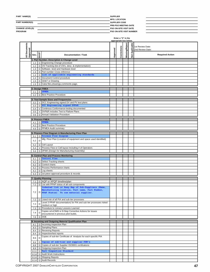
COPYRIGHT 2007 DAIMLERCHRYSLER CORPORATION 47
PART NAME(S)
PART NUMBER(S)
CHANGE LEVEL(S)
0
1st Review Date:2nd Review Date:
Sec.
D/V
/F*
Documentation / Task
0 1. Part Number, Description & Change Level1.2 D Engineering Change procedure
1.2 D CN Tracking (list of CN's, desc. & implementation)
1.3 D Software level and Hardware level
1.3 D Part number Cross reference
1.4 D List of applicable engineering standards
1.4 D Document Control procedure
1.5 D GD&T or Drawing
1.5 D Catia files,drawings,comments page,0
0 2. Design FMEA2.1 D DFMEA
2.2 D Best Practice Procedure0
0 3. Test Sample Sizes and Frequencies3.2 V DCC Engineering signed DV and PV test plans
3.3 D DCC Engineering signed DVP&R
3.4 V Continous Conformance testing documented
3.5 V DVP&R includes Test to Flailure Plans
3.6 D Annual Validation Procedure0
0 4. Process FMEA4.1 D PFMEA
4.2 D Best Practice Procedure
4.5 D PFMEA Audit summary0
0 5. Process Flow Diagram & Manufacturing Floor Plan5.1 D Process Flow diagram
5.2 DMfg. Floor Plan (Location of equipment and space used identified)
5.2 D Cell Layout
5.4 V Process Flow or Cell layout Including # of Operators
5.6 D DFMA (Design for Manufacturing Assembly)0
0 6. Control Plan and Process Monitoring6.1 D Control Plan
6.2 D Defect Tracking sheets
6.2 D Control charts
6.2 D Process Performance charts
6.2 D Log sheets
6.3 D 1st piece approval procedure & records0
0 7. Quality Planning7.1 D AQP or APQP timeline/plan7.2 D List with PPAP status of all sub components
7.2 D
Indented list or Easy Map of Sub-Suppliers (Name, Manufacturing location, Part name, Part Number, PPAP Status) To raw material supplier.
7.2 D Listed risk of all PIA and sub-tier processes
7.2 DLevel 3 PPAP documentation( for PIA and sub tier processes risked medium or high
7.3 D Procedure to convey Lessons Learned
7.4 DCopies od eCIMS or 8-Step Corrective Actions for issues encountered in previous pilot builds.
7.6 D DOE0
0 8. Incoming and Outgoing Material Qualification Plan8.1 D Incoming Inspection Plan
8.3 D Sampling Plans
8.4 D Receiving Reports
8.4 D Inspection/test reports
8.6 DCopies of sub-tier Certificate of Analysis for each specific PIA
8.6 D Copies of sub-tier and supplier PSW's
8.8 D Copies of sub-tier Supplier ISO9001 certifcations
8.9 D Outgoing Inspection Plan
8.11 D Part Inspection Standard
8.14 D Audit Work Instructions
8.14 D Shipping Reports
8.14 D Audit Records
PRE-PSO MEETING DATE
PSO ON-SITE VISIT DATE
SUPPLIER
SUPPLIER CODE
MFG. LOCATION
Mis
sing
/Rej
ect
PROGRAM
Enter a "X" in the appropriate box below.
Not
App
licab
le
All
Doc
umen
ts
App
rove
dPSO ON-SITE VISIT NUMBER
Required Action
App
rove
d
Cor
rect
ions

COPYRIGHT 2007 DAIMLERCHRYSLER CORPORATION 48
0 9. Parts Handling Plan - WIP9.1 D Parts Handling Plan
9.1 D Material handling Procedures
9.7 D Containment records0
0 10. Operator Instructions10.1 D Operator Instructions
10.1 D Set-up Sheets
10.1 D 1st Piece approval instructions
10.1 D Mistake proofing instructions
10.1 D Gage Instructions
10.2 D Operator Qualification process
10.3 D Visual Management Document control procedure
10.4 D Rework/repair instructions0
0 11. Tooling, Equipment & Gages Identified11.1 D Tooling List (Including Capital Equipment)
11.2 D STR (List)(Printed from DCX system)
11.2 N
Note: "Property of DCX" and the STR number must be on all DCX owned tooling (Fire Proof). The STR list printed from the DCX system needs to be supplied to the specialist during the PSO Onsite visit.
00 12. Special Product & Process Characteristics Identified
12.1 D Special Characteristics List
12.1 D PPSR (Pre-Production Sample Report) for vehicle builds
12.5 D
FPSC (First ProductionShipement Certification) Plan -100% inspection of 1st 2000 GOOD parts for visual defects and all Control plan checks (Or increased frequency per team agreement)
00 13. Error & Mistake Proofing
13.1 D Error & Mistake Proofing Plan
13.1 DList of error and mistake proofing implmented by operation number
13.1 D Error & Mistake Proofing Studies
13.2 D Mistake Proofing Contingency Plan0
0 14. Layered Process Audit Plan14.2 D LPA Procedures
14.2 D LPA work instructions
14.3 D LPA Structure and Frequency chart
14.4 D LPA Process Control Audit checklist
14.4 D LPA Error Proofing Verifcation Audit Checklist0
0 15. SRE Results and Evidence of Product Specifications
15.1 FSRE "Supplier Readiness Evaluation" Run results
15.4 F Measurement Verification Report0
0 16. Production Demonstration Run and FTC16.1 F Line Speed demonstration form completed
16.4 D Process Constraints & Contingency Plans
16.4 F Final audit sampling plan0
0 17. Parts Packing & Shipping Specifications17.1 D Parts packaging and shipping plan
17.1 D Packaging and Shipping procedures
17.1 D Packaging,shipping and labeling instructions
17.1 D Returnable Container management plan
17.1 D Barcoded Labeling Procedure
17.2 D Shipping label example
17.3 D Simulation or shipping test results0
0 18. Gage & Test Equipment Evaluation18.3 D Gage R&R (All measurement devices) results
18.2 D Gage layout results
18.5 D Gage and test equipment validation procedure
18.5 D Gage and test equipment calibration records
18.6 D Calibration schedule0
0 19. Preventative Maintenance Plans19.1 D PM Plan (Everything on Tooling list is in System)
00 20. Initial Process Study
20.1 F Initial Process Study results
00 21. Production Validation Testing Complete
21.1 D Component level PV test results21.1 D PV test procedures21.4 D Training/certification for BSR operators21.4 D Applicable PF Standards21.4 D Vibration Test Procedure
0Key: D Document
F Completed PSO formN NoteV View
Powerway required document

COPYRIGHT 2007 DAIMLERCHRYSLER CORPORATION 49
20 26"N" "Z" "A"
PART NAME(S) SUPPLIER
MFG. LOCATION
SUPPLIER CODE
PRE-PSO MEETING DATE
PSO ON-SITE VISIT DATE
PSO ON-SITE VISIT NUMBER
FPSC REVIEWED WITH SUPPLIER
Accept Reject N/A Accept Reject N/A
1. PART NUMBER, DESCRIPTION and CHANGE LEVEL 0 0 02. DESIGN FMEA 0 0 03. TEST SAMPLE SIZES and FREQUENCIES 0 04. PROCESS FMEA 0 05. PROCESS FLOW DIAGRAM and MFG FLOOR PLAN 0 06. CONTROL PLAN and PROCESS MONITORING 0 07. QUALITY PLANNING 0 08. INCOMING and OUTGOING MATERIAL QUALIFICATION PLAN 0 09. PARTS HANDLING PLAN 0 0
10. OPERATING INSTRUCTIONS 0 011. TOOLING, EQUIPMENT and GAGES IDENTIFIED 0 012. SPECIAL PRODUCT and PROCESS CHAR IDENTIFIED 0 013. ERROR and MISTAKE PROOFING 0 014. LAYERED PROCESS AUDIT 0 015. SUPPLIER READINESS EVAL and EVIDENCE OF PRODUCT SPECS 0 016. LINE SPEED DEMONSTRATION and FTC 0 017. PARTS PACKAGING and SHIPPING SPECS 0 018. GAGE and TEST EQUIPMENT EVALUATION 0 019. PREVENTIVE MAINTENANCE PLANS 0 020. INITIAL PROCESS STUDY 0 0
20 20 0
Accept Reject N/A Accept Reject N/A
21. PRODUCTION VALIDATION TESTING COMPLETE 024 15 2 2
Yes No Date
Yes No Date
Manufacturing Facility
PRINT NAME, SIGN AND DATE PRINT NAME, SIGN AND DATE
PRINT NAME, SIGN AND DATE PRINT NAME, SIGN AND DATE
PRINT NAME, SIGN AND DATE PRINT NAME, SIGN AND DATE
PRINT NAME, SIGN AND DATE PRINT NAME, SIGN AND DATE
DATE
PART NUMBER(S)
0
PROCESS
PROGRAM
CHANGE LEVEL(S) 0
0
0
DOCUMENTATION
0
OPTION #
0 0
0
0
DAIMLERCHRYSLER PROCESS SIGN-OFF CHECKLIST
PSO APPROVAL STATUS: CHECK IF PSO EXTENDED RUN:
1/0/1900
Process Sign-Off Team
ENGINEERING
0
0
PROCESS
SUPPLIER QUALITY
PSO PROCESS ELEMENTS REQUIRED FOR "Z" APPROVAL
CORRECTIVE ACTION REQUIRED
ON-SITE REVISIT REQUIRED
DOCUMENTATION
ADDITIONAL PSO PROCESS ELEMENTS REQUIRED FOR "A" APPROVAL

COPYRIGHT 2007 DAIMLERCHRYSLER CORPORATION 50
PART NAME(S) SUPPLIER
MFG. LOCATION
SUPPLIER CODE
PRE-PSO MEETING DATE
PSO ON-SITE VISIT DATE
PSO ON-SITE VISIT NUMBER
0
TARGET DATE
CLOSED DATE
RESPONSIBILITY
0
0
1/0/1900
0
0
0
PART NUMBER(S)
0
0
CHANGE LEVEL(S)
PROCESS SIGN-OFF COMMENTS SHEET
0
0
0
PROGRAM
ITEM ISSUE/ACTION

COPYRIGHT 2007 DAIMLERCHRYSLER CORPORATION 51
PR
E-P
SO
ME
ETI
NG
DAT
E
CH
ANG
E L
EV
EL(
S)
PS
O O
N-S
ITE
VIS
IT D
ATE
PS
O O
N-S
ITE
VIS
IT N
UM
BER
QU
AN
TITY
DE
TER
MIN
ED
BY
SU
PP
LIE
R A
ND
SR
E L
INE
RA
TE:
DA
IMLE
RC
HR
YS
LER
PS
O T
EA
M:
SH
IFT:
Item
# 1 2 3 4 5 6 7 8 9 10 11 12 13 14 15 16
PE
RFO
RM
ANC
E R
ES
ULT
SP
roce
ss F
eatu
re /P
art
Cha
ract
eris
ticP
roce
ss
/Par
t1
PAR
T N
AME
(S)
PR
OG
RAM
SU
PP
LIE
R N
AME
MFG
. LO
CAT
ION
0
0
0 0
0
0
PAR
T N
UM
BER
(S)
SU
PP
LIE
R C
OD
E
SU
PP
LIE
R R
EAD
INE
SS
EV
ALU
ATIO
N
Mea
s.
Freq
.U
SL
UC
LP
art/P
roc
Avg
.LC
LLS
LP
pP
pkQ
uant
ity
Atte
mpt
edQ
uant
ity
Acc
epte
dFT
C P
erce
nt (w
ithou
t re
pairs
)A
CC
/ RE
J%
GR
&R
1/0/
1900
0
0
0 0 05t
h E
ditio
n

COPYRIGHT 2007 DAIMLERCHRYSLER CORPORATION 52
Supplier Readiness Evaluation Instructions Note: When requesting approval for multiple manufacturing lines, a SRE form shall be completed for each manufacturing line requesting approval. Quantity Determined by Supplier and DaimlerChrysler PSO Team: Number of parts agreed by DaimlerChrysler and the Supplier prior to the SRE run. SRE Line Rate: The calculated line rate for the Supplier Readiness Evaluation run = SRE Part Quantity Accepted ÷ Duration of SRE run. Shift: The manufacturing shift the SRE was performed. Record shift # and hours. (e.g. 1st shift, 6am-3pm) Process Feature/Part Characteristic: The process feature or part characteristic that is being measured. Process/Part: Document if data is for a process measurement or a part measurement. Meas. Freq.: Measurement Frequency. Record the number of part/process measurements taken per time interval. USL: Upper Specification Limit. The upper limit of the part or process specification per the part drawing or process standard. UCL: Upper Control Limit: The upper limit established by the Supplier for process/part control. NOTE: This number should be less than the USL. Part/Proc. Avg.: Part/Process Average. The average of all measured process features/part characteristics. LCL: Lower Control Limit. The lower limit established by the Supplier for process/part control. NOTE: This number should be less than the LSL. LSL: Lower Specification Limit. The lower limit of the part or process specification per the part drawing or process standard. PP: The calculated PP for all measured process features/part characteristics. PPK: The calculated PPK for all measured process features/part characteristics. Quantity Attempted: The total number of part/process measurements taken. Quantity Accepted: The total number of part/process measurements acceptable per the established controls (within the LCL-UCL). FTC percent (without repairs): Calculated First Time Capability. For further details, please see Appendix C. % GR&R: Calculated percentage of Gage R&R for gage used for part/process measurement. Acc/Reject: Has the PSO team determined the supplier’s data to be acceptable (acc) or unacceptable (Reject)? [i.e. LCL <Proc Avg < UCL; Ppk � Ppk matrix requirement (see Initial Process Study element); FTC � 90%; GR&R < 10% ; 10< GR&R < 30 – PSO team decision].

COPYRIGHT 2007 DAIMLERCHRYSLER CORPORATION 53
PART NAME(S) SUPPLIER
MANUFACTURING LOC
PART NUMBER(S) SUPPLIER CODE
PRE-PSO MEETING DATE
CHANGE LEVEL(S) PSO ON-SITE VISIT DATE
PSO ON-SITE VISIT NUMBER
������������������� ����
Calculation � ������� ������ � Input informationData input from production P.O.:
Shared Line? Yes or No (Y/N)A) Combined DCC P.O. Daily Tooling Capacity
A1) DCC P.O. Daily Tooling Capacity Part Number Pieces/dayA2) DCC P.O. Daily Tooling Capacity Part Number Pieces/dayA3) DCC P.O. Daily Tooling Capacity Part Number Pieces/dayA4) DCC P.O. Daily Tooling Capacity Part Number Pieces/dayA5) DCC P.O. Daily Tooling Capacity Part Number Pieces/day
Total (A1 + A5) Pieces/dayB) DCC P.O. Shift Pattern
B1) Number of shifts per day shiftsB2) Production hours per shift hoursB3) Number of production days per week days
Data input from manufacturing process:C) Downtime ��������
C1) Lunches hours/shiftC2) Breaks hours/shiftC3) Changeover and/or set-up hours/shiftC4) Operating time dedicated to other customers hours/shift��������
C5) Scheduled/unscheduled downtime (as applicable) hours/shift��������
D) Parts attempted during the PDR attempted partsE) First time through fallout during the PDR failed partsF) Length of PDR in hours Start: Finish: hoursG) Acceptable parts witnessed at the PDR pieces
In process calculations:
H) Available production hours/shift [B2-(C1+C2+C3+C4+C5)] hours/shiftI) Available production hours/day [B1*H] hours/dayJ) DCC required parts per hour at the PDR [A/I] parts/hourK) Witnessed parts per hour at the PDR [G/F] parts/hour
Requirements:
L) FTC calculation [((D-E)/D)*100] ���� ����� ������������� %M) Difference between witnessed parts/hour and required parts/hour [K-J] pieces �����������������������������
DCC FORMULA FOR PRODUCTION DEMONSTRATION RUN PSO REQUIREMENT
0
0
0
0
0
0
0
0
0
PROGRAM 0
0
0

COPYRIGHT 2007 DAIMLERCHRYSLER CORPORATION 54
Shared Line? Yes or No (Y or N)
A) The combined DCC Daily Tooling Capacity should be obtained from the DCC Purchase Order - "TOOL CAP"If shared line = N:A1) Input the Daily Tooling Capacity and part number from the DCC Purchase Order.A2-A5) Leave as the default 0.
If shared line = Y, shared with DCC parts only:A1-A5)
If shared line = Y, shared with other customers:A1-A5) Input the Daily Tooling Capacity from the DCC Purchase Order for the various parts being validated.C4) In hours/shift, input the time dedicated per shift to other customers.
B) The shift pattern should be obtained from the DCC Purchase Order - "SH/HR/DY"B1) Number of shifts per day - "SH" on Purchase OrderB2) Production hours per shift - "HR" on Purchase OrderB3) Number of production days per week - "DY" on Purchase Order
C) Downtime per shiftC1) Lunches - The amount of time, in hours per shift, that the production process is not operating due to lunch.C2) Breaks - The amount of time, in hours per shift, that the production process is not operating due to breaks.C3)
C4)
C5)
D) The parts attempted during the PDR are the total number of parts the supplier produced including rejects/scrap.
E)
F)
G)
NOTE: Please indicate when during the production process the changeovers will be implemented (if they are conducted during the quoted operating pattern, or if they are to be conducted during "off shifts").
Length of PDR in hours is the measured time it took to conduct the production demonstration run. Please input start and finish time in cells provided.
Scheduled/unscheduled downtime not considered - The amount of downtime, in hours per shift, that was not considered. This could be any downtime such as PM, changeover, etc. that was not included in the development of the shift pattern/pieces per day quantity.Scheduled/unscheduled downtime should be calculated on a per shift basis (e.g. operating time per week divided by the number of shifts per week = changeover time per shift).
NOTE: Please input appropriate comments in the blanks provided.
Operating time dedicated to other customers - The amount of time, in hours per shift, that the production process is operating/manufacturing product for other customers.Operating time dedicated to other customers calculated on a per shift basis (e.g. operating time per week divided by the number of shifts per week = changeover time per shift).
NOTE: Please input appropriate comments in the blanks provided.
First time through fall out during the PDR is the number of parts that were rejected from the manufacturing process during first evaluation. This is not the final number of unacceptable parts, but only those that failed first time through the process. (This number will be used in the FTC calculation.)
NOTE: The assumption for this calculation is that all of the part numbers have the same operating pattern and the same takt time.
NOTE: Please input appropriate comments in the blanks provided.
Changeover and/or set up - The amount of time, in hours per shift, that the production process is not operating due to changeover and/or set up activities. Only changeovers that were quoted to occur during the production operating pattern should be considered for this calculation.
Changeovers or set up not conducted every shift should be calculated on a per shift basis (e.g. Changeover time per week divided by the number of shifts per week = changeover time per shift).
Production Demonstration Run Calculation Work Instructions
Acceptable parts witnessed at the PDR are the total number of parts, minus any rejects, which were demonstrated during the production run. (May differ from first time through fallout.)
NOTE: If the components being validated have varying operating patterns or different takt times, then separate calculation worksheets should be completed for each part.
NOTE: If the components being validated have varying operating patterns or different takt times, then separate calculation worksheets should be completed for each part.
NOTE: The assumption for this calculation is that all of the part numbers have the same operating pattern and the same takt time.
Input the Daily Tooling Capacity and part number from the DCC Purchase Order for the various parts being validated.
COPYRIGHT 2007 DAIMLERCHRYSLER CORPORATION 55
H)
I) Available production hours/day are the net hours per day the supplier has available to build product.
J)
K)
L)
If the DCC requirement of 90% or greater is met, the cell will turn green.If the DCC requirement is not met (less than 90%), the cell will turn red.
M)
If the part difference is less than 0, the cell will turn red indicating the requirement is not met. i.e. M < 0 the cell = red.
NOTE: In the event (M) is yellow, it is strongly advised to conduct an Extended Run PSO to stress the supplier's production line and increase confidence in the supplier's ability to meet DCC requirements. PSO Extended Run options are explained in the PSO manual. Continuous improvement actions should also be developed for bottleneck operations or other operations which showed poor performance during the PSO run.
NOTE: If the FTC is less than 90%, the PSO team shall take product and process technology, complexity, supplier experience, and the effectiveness of defect containment actions into account when deciding whether the demonstrated lower FTC values are acceptable with a documented deviation. A DCC Supplier Quality Manager's signed approval is required for deviation from the PSO FTC requirement.
The difference between required parts/hour and witnessed parts/hour gives the total number of parts over or under the DCC requirement.
Production Demonstration Run Calculation Work Instructions, cont.
If the part difference is greater than (the DCC required parts per hour + 10%), the cell will turn green indicating the line speed is acceptable. i.e. (J + 10%) � M, then cell = green (requirements met).If the part difference is between 0 and (the DCC required parts per hour + 10%), the cell will turn yellow indicating the line speed has met requirments, but the part difference is very close and may require additional attention. i.e. 0 <= M < (J+10%) then cell = yellow.
FTC (First Time Capability) is the percentage of acceptable parts witnessed at the production demonstration run out the total number of parts attempted at the PDR.
Available production hours/shift are the net hours per shift the supplier has available to build product not including any scheduled downtime.
DCC required parts per hour at the PDR are the total number of acceptable parts the supplier must produce, in an hour's time, necessary to satisfy DCC.
Witnessed parts per hour at the PDR are the number of acceptable parts witnessed by the PSO team, which the supplier produced within an hour's time.

COPYRIGHT 2007 DAIMLERCHRYSLER CORPORATION 56
Item
# 1 2 Item
# 1 2 3 4 5 6 7 8 9 10 11 12 13 14 15 16
% G
R&
R
9.37
%
Mea
s.
Freq
.U
SL
Pro
cess
Fea
ture
/ P
art
Cha
ract
eris
tic
P02
5 G
ap -
Mac
hine
66
Par
t2.
280.
0089
50.
0874
0.08
51
P02
5 G
ap -
Mac
hine
67
Pro
cess
Fea
ture
/ P
art
Cha
ract
eris
tic
Par
t
Qua
ntity
Atte
mpt
ed
30 30
0.09
7
0.09
7
2/S
hift
2/S
hift
Pro
cess
/Par
t1
Par
t/Pro
c A
vg.
0.00
895
2.54
0.07
72.
410.
0851
Pp
Ppk
0.08
74
Pro
cess
/Par
t1LC
LLS
L
AC
C/ R
EJ
AC
C
AC
C
100%
100%
Qua
ntity
A
ccep
ted
30 3012
.70%
% G
R&
RQ
uant
ity
Acc
epte
dFT
C P
erce
nt (w
ithou
t re
pairs
)
Ppk
0.07
72.
5
Qua
ntity
Atte
mpt
ed
Sum
mar
y Ex
ampl
eLC
LLS
LP
pU
CL
Par
t/Pro
c A
vg.
Mea
s.
Freq
.U
SL
UC
L
FTC
Per
cent
(with
out
repa
irs)
1/0/
1900
0
PAR
T N
UM
BER
(S)
PAR
T N
AME
(S)
CH
ANG
E L
EVE
L(S
)0
0
0
PRO
GR
AM
MFG
. LO
CAT
ION
SU
PPL
IER
CO
DE
PSO
ON
-SIT
E V
ISIT
DAT
E
PR
E-P
SO M
EE
TIN
G D
ATE
PSO
ON
-SIT
E V
ISIT
NU
MBE
R0
0
0
0
INIT
IAL
PR
OC
ESS
STU
DY
SU
PPL
IER
0
0 0
AC
C/ R
EJ
Dai
mle
rChr
ysle
r
5th
Edi
tion

COPYRIGHT 2007 DAIMLERCHRYSLER CORPORATION 57
Initial Process Study Process Feature/Part Characteristic: The process feature or part characteristic that is being measured. Process/Part: Document if data is for a process measurement or a part measurement. Meas. Freq.: Measurement Frequency. Record the number of part/process measurements taken per time interval. USL: Upper Specification Limit. The upper limit of the part or process specification per the part drawing or process standard. UCL: Upper Control Limit: The upper limit established by the Supplier for process/part control. NOTE: This number should be less than the USL. Part/Proc. Avg.: Part/Process Average. The average of all measured process features/part characteristics. LCL: Lower Control Limit: The lower limit established by the Supplier for process/part control. NOTE: This number should be less than the LSL. LSL: Lower Specification Limit. The lower limit of the part or process specification per the part drawing or process standard. PP: The calculated PP for all measured process features/part characteristics. PPK: The calculated PPK for all measured process features/part characteristics. Quantity Attempted: The total number of part/process measurements taken. Quantity Accepted: The total number of part/process measurements acceptable per the established controls (within the LCL-UCL). FTC percent (without repairs): Calculated First Time Capability. For further details, please see Appendix C. % GR&R: Calculated percentage of Gage R&R for gage used for part/process measurement. Acc/Reject: Has the PSO team determined the supplier’s data to be acceptable (acc) or unacceptable? [i.e. LCL <Proc Avg < UCL; PP � PPK matrix requirement (see Initial Process Study element); FTC � 90%; GR&R < 10% ; 10%< GR&R < 30% – PSO team decision].

COPYRIGHT 2007 DAIMLERCHRYSLER CORPORATION 58
PR
E-P
SO
ME
ET
ING
DA
TE
CH
AN
GE
LE
VE
L(S
)P
SO
ON
-SIT
E V
ISIT
DA
TE
PS
O O
N-S
ITE
VIS
IT N
UM
BE
R
- - - - - -
ME
AS
UR
EM
EN
T S
YS
TE
M R
EP
OR
T
0
0
0
0
PR
OG
RA
M
0
0
0
PA
RT
NU
MB
ER
(S)
0 0
0
CH
AR
AC
TE
RIS
TIC
SP
EC
IFIC
AT
ION
Hol
e S
ize
(3.6
- 7
.5 m
m)
Var
iab
le d
ata
is p
refe
rred
bu
t attr
ibut
e d
ata
is a
ccep
tabl
e.
All
devi
atio
ns
sha
ll be
list
ed in
the
CO
MM
EN
TS
se
ctio
n o
f th
is d
ocu
men
t.
(2.0
± 0
.02
mm
)Le
ngth
ME
TH
OD
OF
ME
AS
UR
EM
EN
TQ
UA
NT
ITY
A
TT
EM
PTE
D
DA
TA
For
attr
ibut
e d
ata
, a 3
0 p
iece
sam
ple
with
one
or
mor
e no
n-co
nfo
rman
ces
is u
nacc
epta
ble.
the
num
ber
of c
har
act
eris
tics
sele
cted
dep
ends
upo
n th
e co
mpl
exity
.
As
part
of t
he P
SO
, the
act
ual m
easu
rem
ent p
roce
ss m
ust b
e w
itnes
sed
by th
e P
SO
Tea
m.
A m
inim
um o
f 3 c
hara
cte
ristic
s ar
e to
be
chec
ked.
Fo
r a
ny g
iven
par
t, as
sem
bly
, or
pro
cess
,
A m
inim
um o
f 30
ra
ndom
ly s
elec
ted
sam
ples
sha
ll be
che
cked
dur
ing
the
PS
O o
n-si
te v
isit.
Ref
er
to th
e P
pk C
apab
ility
Mat
rix
(App
end
ix B
of t
he
PS
O 5
th E
ditio
n M
anua
l) fo
r P
pk r
equ
irem
ents
.
PR
OC
ES
S A
CC
/RE
JQ
UA
NT
ITY
A
TT
EM
PTE
D
Witn
esse
d B
y:
CH
AR
AC
TE
RIS
TIC
SP
EC
IFIC
AT
ION
ME
TH
OD
OF
ME
AS
UR
EM
EN
TP
P /
PP
KFT
C P
ER
CE
NT
AG
E
(with
out r
epai
r)Q
UA
NT
ITY
A
CC
EP
TE
D
Num
ber
of p
arts
witn
esse
d:
CO
MM
EN
TS
:
CA
LIP
ER
28C
MM
MA
CH
INE
100%
93%
2.3/
2.2
30
QU
AN
TIT
Y
AC
CE
PT
ED
30
SU
MM
AR
Y E
XA
MP
LE
1.7/
1.6
RE
J30
AC
C
PP /
PP
KP
RO
CE
SS
AC
C/R
EJ
FTC
PE
RC
EN
TA
GE
(w
ithou
t rep
air)
PA
RT
NA
ME
(S)
0 1/0/
1900
SU
PP
LIE
R N
AM
EM
FG
. LO
CA
TIO
N
SU
PP
LIE
R C
OD
ED
aim
lerC
hry
ler

COPYRIGHT 2007 DAIMLERCHRYSLER CORPORATION 59
Measurement System Report Instructions
The MEASUREMENT SYSTEM VERIFICATION REPORT is used to document the results of the measurement audit performed during the PSO On-Site Visit. Use additional copies of the form or attach additional pages as needed to accommodate more characteristics. Number of parts witnessed: The number of parts the PSO has personally witnessed the supplier measure characteristics. Witnessed by: The names of all the DCC PSO team members who witnessed the measurement audit. Characteristic: Measurement characteristics identified by the team to be measured. Specification: The documented specification of the characteristics as identified on the part drawing. Method of Measurement: The gage, fixture, or equipment used to measure the identified characteristics. Quantity Attempted: The total number of parts chosen to be measured by the team (this may exceed the number of parts witnessed by the PSO team members). Quantity Accepted: The number of parts which whose characteristic was within the specification. FTC percentage (without repair): Calculated FTC. For further details, please see Appendix C. PP/PPK: The calculated PP/PPK for the quantity of parts attempted. Process Acc/Reject: Has the PSO team determined the supplier’s measurement process to be acceptable (acc) or unacceptable (Reject)? Comments: Any waivers/deviations should be recorded here for documentation purposes.

COPYRIGHT 2007 DAIMLERCHRYSLER CORPORATION 60
How to find the Daily Tooling Capacity and Operating Pattern For DaimlerChrysler Specialists: � Log onto the Supplier Quality Portal at https://gsp.extra.daimlerchrysler.com/SQP/servlet/SQPServlet � Move mouse to “Summaries” and click on “Part Summary” from the drop-down menu � Enter the part number and click on the “Fetch” box � Additional MY information can be found by moving the mouse over the indicated area

COPYRIGHT 2007 DAIMLERCHRYSLER CORPORATION 61
APPENDIX B Tables and Examples

COPYRIGHT 2007 DAIMLERCHRYSLER CORPORATION 62
LOT ACCEPTANCE SAMPLING TABLE
NOTE 1: THIS TABLE APPLIES TO ATTRIBUTE SAMPLING ONLY. NOTE 2: TWO OR MORE OF THE METHODS DESCRIBED IN ELEMENT 7.4.3.1 OF TS-16949 SHALL BE USED, OTHERWISE, THIS TABLE APPLIES. Characteristics Definition
SAFETY <S>/EMISSION <E>: A characteristic that will affect compliance with DaimlerChrysler Corporation and/or Governmental Vehicle Safety/Emission requirements. KEY <D>: A characteristic that is key to part function and has particular quality, reliability, and durability significance (Refer to Engineering Process Standard PS-7300).
Sample size shall be based upon the normal production lot size. If the lot size is temporarily reduced due to material shortages or production problems, the sample size will not change. If the temporarily reduced lot size is smaller than the required, production sample size, inspect 100%. A lot is not to exceed one shift or one-day's production whichever is smaller.
PRODUCT QUALIFICATION
Sample Size Per Characteristic Classification Acceptance Number = 0
Lot Size or Shipment Size*
<S> / <E>
<D> 0-15
100% Inspection
16-25
26-50
51-75
50
76-125
75
65
126-225
90
75
226-425
100
85
426-1300 110 90
1301 and up 115 90
SAMPLE RESULTS
ACTIONS ON PROCESS
ACTIONS ON LOT
No Nonconforming units
Continue to operate
Accept
One or more Nonconforming units
Find Root Cause(s) and Correct Process
Sort 100% since last conforming lot

COPYRIGHT 2007 DAIMLERCHRYSLER CORPORATION 63
CAPABILITY MATRIX
There are two risks inherent in every decision, either (1) we have accepted “bad” parts (consumer’s risk), or (2) we have rejected “good” parts (producer’s risk). Test plans seek to balance these risks by specifying sample size and/or acceptance criteria so that neither the consumer nor the producer carries the higher proportion of risk. Sometimes, for business or other reasons, it may be important to hold one risk constant and allow the other risk to “float” based on sample size. Such is the case for Pp and Ppk. DaimlerChrysler wants to minimize its risk of accepting a population below 1.33Ppk. The following table presents the sample size and acceptance criteria that keeps the risk of accepting a “bad” population (� 1.33) at 6.4% (93.6% that population > 1.33 Ppk will be accepted). Depending upon sample size, the risk of rejecting a “good” population (� 1.67) could be very high. The table allows for trade-offs between sample size and producer’s risk to be identified.
Sample Size Acceptance Ppk
Criteria Risk of Accepting a
Population <= 1.33Ppk Risk of Rejecting a
Population >= 1.67Ppk 5 2.94 6.4 % 86.3% 10 2.10 6.4 % 77.3% 15 1.89 6.4 % 68.7% 20 1.78 6.4 % 60.7% 25 1.71 6.4 % 53.3% 30 1.67 6.4 % 46.5% 35 1.64 6.4 % 40.4% 40 1.61 6.4 % 34.9% 45 1.59 6.4 % 30.1% 50 1.58 6.4 % 25.8% 55 1.56 6.4 % 22.0% 60 1.55 6.4 % 18.7% 65 1.54 6.4 % 15.9% 70 1.53 6.4 % 13.4% 75 1.52 6.4 % 11.3% 80 1.52 6.4 % 9.5% 85 1.51 6.4 % 8.0% 90 1.50 6.4 % 6.7% 95 1.50 6.4 % 5.6% 100 1.49 6.4 % 4.7% 150 1.46 6.4 % 1.9% 200 1.44 6.4 % 1.0% 250 1.43 6.4 % 0.6% 300 1.42 6.4 % 0.3%

COPYRIGHT 2007 DAIMLERCHRYSLER CORPORATION 64
EXAMPLE: LPA FREQUENCY AND STRUCTURE
Assigned Management Category(example)
Assigned Management Personnel(example)
Audit Assignment D
epar
tmen
t A
Dep
artm
ent B
Dep
artm
ent C
Dep
artm
ent D
Dep
artm
ent E
Dep
artm
ent F
1st Layer of Management
Supervisors Supervisor 1 Own Department1 per shift
1 per shift
Supervisor 2 Own Department1 per shift
1 per shift
Supervisor 3 Own Department1 per shift
1 per shift
2nd Layer of Management Area
Managers Area Manager 1 Own Area2 per week
2 per week
2 per week
2 per week
Area Manager 2 Own Area2 per week
2 per week
3rd Layer of Management
Plant Staff and Plant Manager Engrng Mgr Rotate Depts.
Quality Mgr Rotate Depts.
Tooling Mgr Rotate Depts.
H.R. Mgr Rotate Depts.
Training Coord. Rotate Depts.
Plant Manager Rotate Depts.
1 per week
1 per week
1 per week
1 per week
1 per week
1 per week

COPYRIGHT 2007 DAIMLERCHRYSLER CORPORATION 65
FMEA GUIDELINES
Special Attention Shall Be Given To:
I. RPN’s that have a Severity � 8 regardless of RPN value, Occurrence level, or Detection level.
II. RPN's that have Severity � 5 and an Occurrence � 2 regardless of Detection and
RPN value. (This equates to customer dissatisfaction and C/1000 >1).
III. Detection = 10. (The potential defect is allowed to leave the plant and reach the field).

COPYRIGHT 2007 DAIMLERCHRYSLER CORPORATION 66
INTENTIONALLY LEFT BLANK

COPYRIGHT 2007 DAIMLERCHRYSLER CORPORATION 67
APPENDIX C FTC Calculations

COPYRIGHT 2007 DAIMLERCHRYSLER CORPORATION 68
First Time Capability
CALCULATING FIRST TIME CAPABILITY (FTC) AND PROCESS YIELD WITHOUT REPAIRS
PURPOSE First Time Capability (FTC) is part of a process capability study that identifies how well it produces quality parts. For multiple assembly lines or tools, FTC studies shall be conducted on each one. FTC can be an important measure, because generally the lower the value, the greater the amount of rework required. As defects and rework increase, there is a greater possibility that the Supplier will ship non-conforming parts. DaimlerChrysler’s requirement for FTC is 90% or greater. Following the PDR, the PSO Team shall review the FTC values for each operation and the overall process. If the FTC is less than 90%, the PSO team shall take product and process technology, complexity, Supplier experience, and the effectiveness of defect containment actions into account when deciding whether the demonstrated lower FTC values are acceptable with a documented deviation. A Supplier Quality Manager’s signed approval is required for deviation from the PSO FTC requirement. FTC can be used to prioritize product and process improvement. If a Supplier encounters a situation where, despite their best efforts, they cannot find a solution to an inherently low FTC, DaimlerChrysler can assist in the improvement effort by supplementing the Supplier's team with experienced engineering and manufacturing specialists from a wide variety of disciplines.
DESCRIPTION FTC is measured as the number of items processed correctly divided by the total number of items processed. Correctly processed means no repairs or rework are allowed. Therefore, in a multi-operation process, a higher FTC is expected for an operation or zone than for an entire process. DATA COLLECTION PROCEDURE This three-step procedure is suggested for calculating a production line FTC. 1. Create a block diagram for the process showing each operation. The flow diagram or floor layout
provided by the plant can also be used.
2. Collect the following data from the PDR. a. Quantity of assemblies attempted. b. Quantity of rejected assemblies from each operation. c. Quantity of acceptable assemblies from the end of the line. Do not include repaired or reworked parts. 3. Calculate the operation and process FTC using the examples as a guide.

COPYRIGHT 2007 DAIMLERCHRYSLER CORPORATION 69
300 Pcs
30 PcsRejected
270 Pcs
Operation 1
First Time Capability
CALCULATIONS & EXAMPLES CALCULATIONS & EXAMPLES
Example 1, Series Process Flow without Repair: During a typical PSO Production Demonstration Run, the goal is to show that the production line is capable of producing parts that meet DCC quality and volume requirements. FTC and Yield are equal for a process without repairs so only FTC calculations will be shown in Section I. For established production lines and carryover component production demonstrations that may include rework, refer to Examples 3 & 4.
Using the three-step, data collection procedure outlined above, the following processed and rejected quantity data were collected during the PDR. The data are shown on the process block diagram.
Figure 1
Example 1 - Series Process Flow Diagram With Demonstration Data Begin by calculating the FTC for each operation. Operation 1 is shown here with its respective PSO PDR data
Divide the quantity completed at Operation 1, 270 units, by the quantity attempted at the operation, 300 units. The result is the operation FTC.
%90or90.0300270
AttemptedQtyCompletedQty
FTC 1Op ���
Figure 1A
In a similar manner, calculate the FTC for each operation in the process using Equation 1. The general operation model is shown in Figure 1B. Table 1 shows a summary of the quantities and FTC’s for the process in Example 1.
AttemptedQtyCompletedQty
FTCOPERATION �
Equation 1
(1) Figure 1B
300 Pcs
30 PcsRejected
270 Pcs 243 Pcs 226 Pcs
9 PcsRejected
217 Pcs
Operation 1
27 PcsRejected
Operation 2
17 PcsRejected
Operation 3 Operation 4
QuantityAttempted
QuantityCompleted
QuantityRejected
OperationNumber

COPYRIGHT 2007 DAIMLERCHRYSLER CORPORATION 70
Operation
Quantity
Attempted
Quantity
Completed
FTC
1
300
270
0.90
2
270
243
0.90
3
243
226
0.93
4
226
217
0.96 TABLE 1 Quantities and FTC’s for Example 1 Enter the calculated operation FTC’s in their respective operation blocks of the process diagram. Calculate the process FTC by dividing the quantity completed for the process, 217 units, by the quantity attempted 300 units.
%3.72or723.0300217
AttemptedQtyTotalCompletedQtyTotal
FTCPROCESS ���
Enter the FTCPROCESS value on the process diagram. The completed Example 1 process diagram is shown in Figure 2. The diagram can be included with the final PSO documents as a record of the process starting capability.
Figure 2
Example 1 - Series Process With Operation and Process FTC's Shown Example 2, Series/Parallel Process Flow without Repair: Using the three-step data collection procedure outlined on page D.2, the following processed and rejected quantity data were collected during the PDR. The data are shown on the process diagram in Figure 3.
Figure 3
Example 2 - Series / Parallel Process Flow Diagram With Demonstration Data
300 Pcs
30 PcsRejected
270 Pcs 243 Pcs 226 Pcs
9 PcsRejected
217 PcsFTC = 72.3%
FTC90%
Operation 1
27 PcsRejected
FTC90%
Operation 2
17 PcsRejected
FTC93%
Operation 3 Operation 4
FTC96%
218 Pcs
300 Pcs
12 PcsRejected
23 Pcs Rejected
288 PcsOperation 1 Operation 2
265 Pcs
91 Pcs
10 PcsRejected
96 PcsOperation 3
2 PcsRejected
94 Pcs
81 Pcs
242 PcsOperation 4
78 Pcs
11 PcsRejected
67 Pcs
Operation 5
Operation 6
24 Pcs Rejected

COPYRIGHT 2007 DAIMLERCHRYSLER CORPORATION 71
Calculate the FTC for each operation in the process using Equation 1 and the operation model shown in Figure 1B on page 2. Table 2 shows a summary of the quantities and FTC’s for the operations in Example 2.
Operation
Quantity
Attempted
Quantity
Completed
FTC
1
300
288
0.96
2
288
265
0.92
3
96
94
0.98
4
91
81
0.89
5
78
67
0.86
6
242
218
0.91
TABLE 2
Quantities and FTC’s for Example 2 Enter the calculated operation FTC’s in their respective blocks on the process diagram. Calculate the process FTC by dividing the total quantity completed, 218 Units, by the quantity attempted, 300 units. The result is the FTC for the process.
%73or726.0300218
AttemptedQtyCompletedQty
FTCPROCESS ���
Add the process FTC to the process diagram. The completed diagram for Example 2 is shown in Figure 4. The diagram can be included with the PDR report to document the initial process performance.
Figure 4 Example 2 – Series / Parallel Process With Operation and Process FTC’s Shown
218 PcsFTC = 72.6%
300 Pcs
12 PcsRejected
FTC96%
23 Pcs Rejected
288 Pcs FTC92%
Operation 1 Operation 2
265 Pcs
91 Pcs
FTC89%
10 PcsRejected
96 PcsOperation 3
FTC98%
2 PcsRejected
94 Pcs
81 Pcs
242 Pcs FTC90%
Operation 4
78 Pcs
FTC86%
11 PcsRejected
67 Pcs
Operation 5
Operation 6
24 Pcs Rejected

COPYRIGHT 2007 DAIMLERCHRYSLER CORPORATION 72
CALCULATING FIRST TIME CAPABILITY (FTC) AND PROCESS YIELD WITH REPAIRS DATA COLLECTION PROCEDURE The recommended procedure for data collection for a process with repair is similar to the procedure shown in Section I. Step #2 differs because of the need to record rework quantities returned to the process stream. Step #3 differs because there are two values to calculate, FTC and yield. 1. Create a block diagram for the process showing each operation. The flow diagram or floor
layout provided by the plant can also be used. 2. Collect the following data from the demonstration run.
a. Quantity of assemblies attempted. b. Quantity of rejected assemblies from each operation. c. Quantity of rejected assemblies that were repaired for each operation. d. Quantity of acceptable assemblies from the end of the line.
3. Calculate the operation and process FTC and yield using the examples as a guide. CALCULATIONS & EXAMPLES Example 3, Series Process Flow with Repair: In some instances, the PDR will be performed on an existing production line with rework operations. These situations require the ability to determine FTC and Yield separately because FTC and Yield are not equal when rework is included. The primary goal for production demonstration is to demonstrate that the production line is ready and capable of producing at the required quality and quantity. Rework is not part of production demonstration. There are times, however, when we must consider the impact of rework on process output. For those times, this section should be used as a guide to calculate FTC and Yield. Using the three-step, data collection procedure outlined above, the following processed and rejected quantity data were collected during a PDR. The data are shown in Figure 5.
Figure 5
Example 3 – Series Process Diagram With Demonstration Data Added
300 Pcs
30 PcsRejected
270 Pcs 268 Pcs 265 Pcs
10 Pcs
Operation 1
27 Pcs
Operation 2 Operation 3 Operation 4
Rework
2 PcsScrap
25 Pcs19 Pcs
Rework
3 PcsScrap
16 Pcs
Rework
1 PcScrap
9 Pcs
264 Pcs

COPYRIGHT 2007 DAIMLERCHRYSLER CORPORATION 73
Calculate the FTC for each operation. Operation 1 is shown here with its respective production demonstration data.
Divide the quantity completed, 270 pieces, by the quantity attempted, 300 pieces. Note: Equation 1 from Section I can be used for this operation because rework was not performed.
Figure 5A %90or90.0300270
AttemptedQtyCompletedQty
FTC 1OP ���
The yield for Operation 1 is the same as the FTC because rework was not performed. Therefore,
%90or90.0300270
Yield 1OP ��
For Operation 2, subtract the quantity rejected, 27 units, from the quantity attempted, 270 units. Divide this total by the quantity attempted. For Operation 2, Equation 2 will provide the correct result because rework was performed.
%90or90.0270243
27027270
FTC
AttemptedQtyjectedReQtyAttemptedQty
FTC
2OP
2OP
���
�
��
Figure 5B Calculate the yield for Operation 2 by dividing the quantity completed, 268 units, by the quantity attempted, 270 units. Refer to Equation 3.
99% or 0.99 = 270268
= tedQty Attemp
CompletedQty = Yield 2 OP
In a similar manner, calculate the FTC and Yield for the remaining operations using Equations 2 and 3. The general operation model is shown in Figure 5C. Table 3 shows the quantities, FTC’s and Yields for the operations in Example 3.
tedQty Attemp
RejectedQty - tedQty Attemp = FTCOperation
Equation 2
tedQty Attemp
CompletedQty = YieldOperation
Equation 3 Figure 5C
268 Pcs
27 Pcs
Operation 2
Rework
2 PcsScrap
25 Pcs
270 Pcs
300 Pcs
30 PcsRejected
270 PcsOperation 1
OperationNumber
QuantityRejected
Rework
QuantityReworked
QuantityAttempted
QuantityCompleted

COPYRIGHT 2007 DAIMLERCHRYSLER CORPORATION 74
Operation
Quantity
Attempted
Quantity Rejected
FTC
Quantity Reworked
Quantity
Completed
Yield
1
300
30
0.90
N/A
270
0.90
2
270
27
0.90
25
268
0.99
3
268
19
0.93
16
265
0.99
4
265
10
0.96
9
264 0.996
TABLE 3 Quantities, FTC’s, and Yields for Example 3 A simplified sketch of the series operations that will be used for the process FTC calculation is shown in Figure 6. Enter the operation FTC’s in their respective blocks on the sketch. Calculate the process FTC by multiplying the individual operation FTC’s together.
Figure 6
Simplified Process Sketch for Example 3
3.72or723.0%96%93%90%90FTC
)4OpFTC)(3OpFTC)(2OpFTC)(1OpFTC(FTC
PROCESS
PROCESS
�����
�
Calculate the process yield using Equation 3.
88% or 0.880 = 300264
= Yield
tedQty AttempCompletedQty
= Yield
PROCESS
PROCESS
Add the operation and process FTC’s and Yields to the process diagram. The completed process diagram for example 3 is shown in Figure 7. The diagram can be included as part of production demonstration report to document the starting process capability.
Figure 7
Example 3 - Series Process With Operation, Process FTC's, and Yield Shown
300 Pcs
FTC=90%
Operation 1 Operation 4
FTC=96%
264 PcsFTC=90%
Operation 2
FTC=93%
Operation 3
300 Pcs
30 PcsRejected
270 Pcs 268 Pcs 265 Pcs
10 Pcs
FTC=90%Yield=90%
Operation 1
27 Pcs
FTC=90%Yield=99%
Operation 2
FTC=93%Yield=99%
Operation 3 Operation 4
FTC=96%Yield=99.6%
Rework
2 PcsScrap
25 Pcs19 Pcs
Rework
3 PcsScrap
16 Pcs
Rework
1 PcScrap
9 Pcs
FTC = 72.3%YIELD = 88.0%
264 Pcs

COPYRIGHT 2007 DAIMLERCHRYSLER CORPORATION 75
Example 4, Series/Parallel Process Flow with Repair: Using the three-step, data collection procedure outlined on page 5, the following processed and rejected quantity data were collected during a demonstration run. The data are shown in Figure 8.
Figure 8 Example 4 - Series / Parallel Process With Demonstration Data Added
Calculate the FTC and yield for each operation using Equations 2 and 3. Notice that Operation 1 does not include any rework so FTC and Yield will be the same. This is not true for any other operation in the Example 4 process. The general operation model is shown in Figure 5C. Table 4 shows a summary of the quantities, FTC’s, and Yields for the operations in Example 4.
Operation
Quantity
Attempted
Quantity Rejected
FTC
Quantity Reworked
Quantity
Completed
Yield
1
300
12
0.96
N/A
288
0.96
2
288
23
0.92
18
283
0.98
3
102
2
0.98
7
107
1.05
4
97
11
0.89
6
92
0.95
5
84
12
0.86
5
77
0.92
6
276
28
0.90
27
275
0.99 TABLE 4 Example 4 Quantities, FTC’s, and Yields Enter the FTC’s and yields that were calculated for Operations 1 through 6 in their respective operation blocks of the process diagram. The entries for Example 4 are shown in Figure 9.
283 Pcs 97 Pcs
11 Pcsto Rwk*
92 Pcs
Operation 4
102 Pcs Operation 3
2 Pcsto Rwk*
107 Pcs
84 Pcs
12 Pcsto Rwk*
77 Pcs
Operation 5
300 Pcs
12 Pcs 23 Pcs
288 PcsOperation 1 Operation 2
Rework
18 Pcs
18 Pcs
5 PcsScrap
Rework*Op 3,4,& 5
7 PcsScrap
276 PcsOperation 6
28 Pcs
Rework
27 Pcs
1 PcScrap
275 Pcs
25 PcsRework*

COPYRIGHT 2007 DAIMLERCHRYSLER CORPORATION 76
Figure 9
Example 4 - Process With Operation FTC's and Yields Shown
The process shown in Figure 9 has three operations in parallel, Operations 3, 4, and 5. To simplify the FTC calculation, reduce the three parallel operations, shown in Figure 9A, to an equivalent, single operation as shown in Figure 9B. Total the quantity attempted and quantity rejected, then enter the values on an equivalent operation sketch such as 9B.
Qty Attempted = 102 + 97 + 84 = 283 Qty Rejected = 2 + 11 + 12 = 25
Figure 9 A Figure 9B
Calculate the equivalent operation FTCEq 3,4, 5. The equivalent single operation FTC calculation using the total attempted quantity, 283 units, and the total rejected quantity, 25 units, is shown below.
91% or 0.912 =
283258
= 283
25 - 283 =
) 84 + 97 + 102 () 12 + 11 + 2 (-) 84 + 97 + 102 (
= FTC
AttemptedQtyjectedReQtyAttemptedQty
FTC
EQ
EQ
��
283 Pcs 97 PcsFTC=89%Yield=95%
11 Pcsto Rwk*
92 Pcs
Operation 4
102 Pcs Operation 3
FTC=98%Yield=105%
2 Pcsto Rwk*
107 Pcs
84 PcsFTC=86%Yield=92%
12 Pcsto Rwk*
77 Pcs
Operation 5
300 Pcs
12 Pcs
FTC=96%Yield=96%
23 Pcs
288 PcsFTC=92%Yield=98%
Operation 1 Operation 2
Rework
18 Pcs
18 Pcs
5 PcsScrap
Rework*Op 3,4,& 5
7 PcsScrap
276 PcsFTC=90%Yield=99%
Operation 6
28 Pcs
Rework
27 Pcs
1 PcScrap
275 Pcs
25 PcsRework*
97 Pcs
11 Pcsto Rwk*
92 Pcs
Operation 4
Rework*Op 3,4,& 5
7 PcsScrap
84 Pcs
12 Pcsto Rwk*
77 Pcs
Operation 5
18 Pcs
102 Pcs Operation 3
2 Pcsto Rwk*
107 Pcs
25 PcsRework*
283 Pcs
Equivalent Operation 3,
4, & 5
25 PcsRejected

COPYRIGHT 2007 DAIMLERCHRYSLER CORPORATION 77
A simplified sketch of the process that will be used for the FTC calculation is shown in Figure 9C. Multiply the individual operation FTC’s together to obtain the FTC for the process, FTCPROCESS.
Figure 9C
Simplified Process Sketch for Example 4
72% or 0.723 = 90%) 91% 92% 96% ( = FTC
) FTC FTC FTC FTC ( = FTC
PROCESS
6EQ21PROCESS
������
Calculate the process yield using Equation 3 as shown below.
%92or917.0300275
Yield
AttemptedQtyCompletedQty
Yield
PROCESS
PROCESS
��
�
Add FTCPROCESS and YieldPROCESS to the process diagram. The completed diagram for Example 4 is shown in Figure 10. The diagram can be included with the final PSO documents as a record of the starting performance.
Figure 10 Example 4 - Series / Parallel Process With Operation and Process FTC's and Yields Shown
FTC=91%
Equivalent Operation 3,
4, and 5
FTC=96% FTC=92%
Operation 1 Operation 2
FTC=90%
Operation 6
283 Pcs 97 PcsFTC=89%Yield=95%
11 Pcsto Rwk*
92 Pcs
Operation 4
102 Pcs Operation 3
FTC=98%Yield=105%
2 Pcsto Rwk*
107 Pcs
84 PcsFTC=86%Yield=92%
12 Pcsto Rwk*
77 Pcs
Operation 5
300 Pcs
12 Pcs
FTC=96%Yield=96%
23 Pcs
288 PcsFTC=92%Yield=98%
Operation 1 Operation 2
Rework
18 Pcs
18 Pcs
5 PcsScrap
Rework*Op 3,4,& 5
7 PcsScrap
FTC = 72%YIELD = 92%
276 PcsFTC=90%Yield=99%
Operation 6
28 Pcs
Rework
27 Pcs
1 PcScrap
275 Pcs
25 PcsRework*

COPYRIGHT 2007 DAIMLERCHRYSLER CORPORATION 78
INTENTIONALLY LEFT BLANK

COPYRIGHT 2007 DAIMLERCHRYSLER CORPORATION 79
APPENDIX D PSO Extended Run

COPYRIGHT 2007 DAIMLERCHRYSLER CORPORATION 80
PSO Extended Run
This activity is intended for new vehicle launches or major vehicle upgrades to reduce the risk of the vehicle launch. It does not impact the PSO approval process described in this manual but is a supplemental activity to further assure a Supplier’s readiness to support the full volume production with capable processes (see Figure 1).
Figure 1
It is important for the PSO Team to decide the type of PSO Extended Run that will be accomplished and the timing, so it can be integrated into the PSO planning process. In some cases there will be additional pieces built or multiple shifts exercised during the Production Demonstration Run and in other cases there will be additional visits made at later dates to ensure readiness as launch approaches.
Due to the variety of manufacturing processes utilized at Suppliers, the final details of a PSO Extended Run for a particular part are decided by the PSO Team. The following reference options (1-5) have historically been used but other, more applicable, options may be developed as indicated in option number 6.
Option Number
Option Description Option Benefit
1
Expanded production of 1000 or more parts during the PSO PDR.
Higher confidence level that the Supplier can sustain line rate over a longer period of time.
2 Perform 2 separate PSO PDRs with the last run occurring prior to S2 MRD.
Confirms that the Supplier can start the process up on multiple occasions and meet capability and line rate.
3
Perform 3 separate PSO PDRs: Prior to S1 MRD Prior to S2 MRD Prior to V1 MRD
Verifies Supplier’s process consistency and validates readiness for V1 Launch.
4 Perform PSO PDRs on multiple shifts at the Supplier.
Ensures operational readiness on all shifts.
5
In addition to the Pre-S1 PSO, perform a post-launch PSO occurring 2-5 weeks after V1 Launch.
Validates the line rate after several weeks of operation.
6
Any combination of the above 5 options or an appropriate variation for the specific commodity.
Allows flexibility to accommodate unique circumstances.
Table 1
PSO Process as described in the PSO manual
PSO Extended Run
Increased confidence of
Supplier readiness on selected parts
COPYRIGHT 2007 DAIMLERCHRYSLER CORPORATION 81
APPENDIX E Forever Requirements

COPYRIGHT 2007 DAIMLERCHRYSLER CORPORATION 82
DCX “Forever Requirements” Process 1. Supplier proposed changes and/or improvements that may require part submission. 2. If changes and/or improvements affect fit, form, function and/or require DCX print modifications�or
have associated costs; then the Supplier must follow the DCX Engineering CN process (i.e., refer to the appropriate DCX procedures).
3. All other proposed changes (part, process, Tier 2 source, etc.) shall follow the “Forever Requirements”
process outlined here. Table 3.1 in the PPAP 4th Edition AIAG manual gives some examples of situations requiring “Forever Requirements” submissions.
�4. Supplier fills out page one (1) of the ‘DCX Forever Requirements/ODD Box Activity Form’. Note: Please
be advised, that this form must be submitted a minimum of three (3) months in advance of the planned change(s) implementation date or within sufficient time for implementation (as determined by DCX).
5. Supplier submits entire ‘DCX Forever Requirements/ODD Box Activity Form’ to the appropriate
Engineer. Note: if the change(s) affects multiple platforms, then the Supplier must submit a copy of the ‘DCX Forever Requirements/ODD Box Activity Form’ to each affected platform Engineer.
6. The Engineer will fill out page two (2) – Section 2.A. If approved by the Engineer, the Supplier will then submit the
entire ‘DCX Forever Requirements/ODD Box Activity Form’ to the appropriate Supplier Quality Specialist. If the change(s) was rejected by the Engineer, then the Supplier must correct the rejected item(s) and resubmit the ‘DCX
Forever Requirements/ODD Box Activity Form’ to the Engineer. Failure to resubmit the form to the Engineer for approval will end the Forever Requirements process for the proposed change(s).
7. After approval by the Engineer, the Supplier Quality Specialist will fill out page two (2) – Section 2.B. If approved by
the Supplier Quality Specialist, the Supplier will submit the form to the appropriate Buyer. If the change(s) was rejected by the Supplier Quality Specialist, then the Supplier must correct the rejected item(s) and resubmit the ‘DCX Forever Requirements/ODD Box activity Form’ to the Supplier Quality Specialist. Failure to resubmit the form to the Supplier Quality Specialist will end the Forever Requirements process for the proposed change(s).
8. After approval by the Supplier Quality Specialist, the Buyer will fill out page two (2) – Section 2.C. If approved by
the Buyer, the submitted change(s) are fully approved by DCX. If the change(s) was rejected by the Buyer, then the Supplier must correct the rejected item(s) and resubmit the ‘DCX Forever Requirements/ODD Box Activity Form’ to the Buyer. Failure to resubmit the form to the Buyer will end the Forever Requirements process for the submitted change(s).
9. The approval (or rejection) process should be concluded by all affected DCX personnel within 10
business days. 10. A fully signed electronic DCX Forever Requirements/ODD Box Activity indicates that DCX approves the
plan ONLY. 11. After the DCX Forever Requirements/ODD Box Activity Form is approved, the Supplier(s) will complete
all remaining tasks including the successful completion of all PER, PSO, PPAP, and other required activities including and appropriate hard copy and/or electronic notification as necessary.
12. After approval by all affected DCX personnel, the Supplier will make copies of the ‘DCX Forever
Requirements/ODD Box Activity Form’ and distribute it to all appropriate DCX personnel as indicated by the Supplier Quality Specialist. In addition, the Supplier will retain the original copy of the fully approved ‘DCX Forever Requirements/ODD Box Activity Form’.
13. Supplier will submit fully approved form(s)�and/or information into Powerway.com as required. Please be advised, the “hard copy format” is being replaced by an electronic Forever Requirement (eFR CN System). Tentative date time frame is early 2007.

COPYRIGHT 2007 DAIMLERCHRYSLER CORPORATION 83
“Forever Requirements” Process Flow
1) Supplier Proposes Change "Forever Requirements" process begins
Does the change affect fit, form,function, or cost?
Follow DCX CN/ODD Box Procedure;"Forever Requirements" process ends
Supplier completes page 1 of "DCX ForeverRequirement Activity" form and submits oneto DCC Product Engineer for each affectedvehicle/platform. Submission must be a
minimum of 90 days before theproposed effective date of the
change(s).
DCC Product Engineer(s) completessection 2.A. of the form
Approved by DCC ProductEngineer?
DCC Approval not provided;"Forever Requirements" process ends
Supplier providesadditional information
as required.
Supplier submits form to DCC ASQPSpecialist
DCC ASQP Specialist completes section2.B. of the form (including Risk Level)
Approved by DCC ASQP Specialist?
Supplier providesadditional information
as required.
Need moreinformation
Need moreinformation
Yes
Yes
Yes
No
No
No
Supplier submits form to DCC Buyer
DCC Buyer completes section 2.C. of form
Approved by DCC Buyer?
Supplier providesadditional information
as required.
Need moreinformation
Yes
No
A

COPYRIGHT 2007 DAIMLERCHRYSLER CORPORATION 84
“Forever Requirements” Process Flow, cont.
A
Supplier given approval to proceed withchange(s). Timing of change(s), including
PSO, is determined/approved by the Team(DCC Buyer, ASQP Specialist, and Product
Engineer, and the Supplier.)
Risk Level (section 2.B. of form)
Follow PSO process for DCCLead PSO
Follow PSO process forSupplier Lead PSO
LowHigh
Supplier successfully completes all PSOrequirements, as well as all requirementsfrom DCC Product Engineering, ASQP
Specialist, and Buyer on page 2 of the form
Supplier completes all Powerway.comrequirements and submits PPAP (as
applicable)
Supplier implements change 100%
"Forever Requirements" process ends

COPYRIGHT 2007 DAIMLERCHRYSLER CORPORATION 85

COPYRIGHT 2007 DAIMLERCHRYSLER CORPORATION 86

COPYRIGHT 2007 DAIMLERCHRYSLER CORPORATION 87
APPENDIX F DCC Internal PSO Requirements

COPYRIGHT 2007 DAIMLERCHRYSLER CORPORATION 88
Internal Powertrain PSO
3 Steps to Approval
PV Testing
Production Demonstration Run (PDR) & Analysis
Documentation

COPYRIGHT 2007 DAIMLERCHRYSLER CORPORATION 89
Internal Powertrain PSO
Documentation The following documentation will be supplied for final PSO approval by the following DCX groups; Product Engineering, Advanced Manufacturing Engineering, and the internal Powertrain Plant.
Product Engineering
� Release Part Prints w/ Change Verification/ Level Identified
� CATIA comments sheet (list of Engineering standards on sheet)
� A copy of applicable performance, process and material standards (PF Standards)
� Engineering’s procedure for documentation revision changes due to part number changes
� Engineering’s procedure for obtaining and distributing CATIA revisions
� DFMEA
� Internal best practice document for DFMEA development
� DVP&R (DaimlerChrysler Engineering signed DV test plan, DaimlerChrysler Engineering signed
completed DVP&R for DV testing, DaimlerChrysler Engineering signed PV test plan)
� Documented waivers for any testing
� Engineering MQAS procedure for Problem Solving
� Supplier definition of and internal requirements for special product and process characteristics
� DaimlerChrysler Engineering signed DVP&R for PV test results – (MANDATORY ENGLISH
DOCUMENT)
� PV test procedures – (MANDATORY ENGLISH DOCUMENT)
� DaimlerChrysler Engineering approved BSR results (if applicable) – (MANDATORY ENGLISH
DOCUMENT)
Advanced Manufacturing Engineering
� AME’s procedure for documentation revision changes due to part number changes
� PFMEA – (MANDATORY ENGLISH DOCUMENT)
� Internal best practice document for PFMEA development
� Process Flow Diagram – (MANDATORY ENGLISH DOCUMENT)
� Manufacturing floor plan
� Work Station Layout
� Dimensional Control Plan
� Best Practice document for developing Control plans (input from FMEA & Control plans for similar
products)
� Authorization to Ship (ATS Package)-Equipment Qualification at the Plant
� AME MQAS procedure for Problem Solving

COPYRIGHT 2007 DAIMLERCHRYSLER CORPORATION 90
� Tooling List
� Tool Layouts
� Assembly Graphics
� Tool & Op Sheets
� Spare Parts List
� Error and mistake proofing plan. This includes a list of error and mistake proofing by operation
number
� Line Speed Simulation
� AME MQAS procedure for gauge identification
� PM plan, schedule, procedure and work instructions
Plant Deliverables
� Plant’s procedure for documentation revision changes due to part number changes
� Plant’s procedure for obtaining and distributing CATIA revisions
� Control Plan – (MANDATORY ENGLISH DOCUMENT)
� Best Practice document for developing Control plans (input from FMEA & Control plans for similar
products)
� PPAP status list
� Plant MQAS procedure for Problem Solving
� Incoming inspection plan and procedures
� Incoming sampling plans
� Receiving reports
� Material standards
� Inspection/test reports
� Parts Handling Plan
� Material Handling procedures
� Packaging Instructions
� Maintenance plan for WIP (work in process) containers
� Copy of Routing cards or travelers
� Operator, 1st piece approval, mistake proofing, set-up, changeover, rework/repair, inspection and
packaging instructions
� Record of operator training
� Operator qualification process
� Documentation control procedure
� Visual management (displays & diagrams)
� First Production Shipment Certification (FPSC) Plan – (MANDATORY ENGLISH DOCUMENT)
COPYRIGHT 2007 DAIMLERCHRYSLER CORPORATION 91
� Control Charts (As Applicable)
� Process Performance Charts (As Applicable)
� Total Production Maintenance charts
� Error and mistake proofing studies
� Mistake Proofing Contingency Plan (in the event mistake proofing becomes inoperable)
� Control Charts (As Applicable)
� Process Performance Charts (As Applicable)
� Total Production Maintenance charts
� Log Sheets
� Defect Tracking Sheets
� Corrective Action Forms
� 1st Piece Approval Procedure & Records
� Measurement System Verification Report – (MANDATORY ENGLISH DOCUMENT)
� Line Speed section on Production Demonstration Results form – (MANDATORY ENGLISH
DOCUMENT)
� Documented deviation to the “300 part or 2 hour” requirement (if applicable)
� Process Constraints (bottlenecks) documented on PSO COMMENTS SHEET
� Final Audit Plan
� Final Audit Procedure
� Final Audit Work Instructions
� Part Inspection Standard (if applicable) - – (MANDATORY ENGLISH DOCUMENT)
� Final Audit Sampling plan
� Shipping Record Example
� Audit Record Example
� Containment Record Example
� Parts Packaging and Shipping Plan
� Packaging and Shipping Procedures
� Packaging, shipping and labeling instructions
� Returnable Container Management Plan
� Barcode Labeling Procedure
� Shipping Label example
� Plant MQAS procedure for gauge identification
� Gage Plan
� Gage R&R results – (MANDATORY ENGLISH DOCUMENT)
� Gage and Test Equipment Calibration Records and validation plan

COPYRIGHT 2007 DAIMLERCHRYSLER CORPORATION 92
� Calibration Schedule & reaction plan
� Initial Process Study results (on Production Demonstration Results form) – (MANDATORY
ENGLISH DOCUMENT)
� Deviations to Initial Process Study requirements documented on the PSO COMMENTS SHEET (if
applicable) – (MANDATORY ENGLISH DOCUMENT)
� Deviation from FTC requirement w/Commodity Supplier Quality Manager signature (if applicable) –
(MANDATORY ENGLISH DOCUMENT)
� Simulation or shipping test results (Corp Mat Handling)
� Warranty process flow diagram – (MANDATORY ENGLISH DOCUMENT)
� Warranty procedures
� Annual Validation Schedule
Production Demonstration Run & Analysis
Internal Powertrain Programs must adhere to the requirements outlined in element 16 of the PSO Manual
PV Testing
Internal Powertrain Programs must adhere to the requirements outlined in element 21 of the PSO Manual.
Internal Powertrain PSO Sign-off Package Requirements
To assure that all Internal Powertrain PSO requirements have been met, the Internal Powertrain Process Sign-off Package should include the following documents
� Internal Powertrain Process Sign-off form along with the deviations list. The sign-off form should include all necessary signatures.
� The Internal Powertrain PSO work sheet. � Production Demonstration Run (PDR) Results Form. (This is a standard PSO document titled Line
Speed Demonstration Results Form) All required forms and reference material can be found on the Internal Powertrain PSO website. http://advmfg.appl.chrysler.com/mfg/stmpdash/pso/index.shtml

COPYRIGHT 2007 DAIMLERCHRYSLER CORPORATION 93
FREQUENTLY ASKED QUESTIONS Please check https://gsp.extra.daimlerchrysler.com/qlty/pso/index.html for the most current version of the FAQ.
COPYRIGHT 2007 DAIMLERCHRYSLER CORPORATION 94
1. How far down do we go with the certification of the extended enterprise? 3rd tier? 4th tier?
Certification down to the production material Suppliers and if applicable any secondary processes/services (e.g. plating, heat treating, etc) would be sufficient.
2. What should our reaction plan be if Suppliers refuse to conduct PSO's on their sub-Suppliers?
PSO is part of DaimlerChrysler's Supplier evaluation and Production Part Approval Process. According to TS-16949 and the DCC Customer-Specific Requirements for TS-16949, Suppliers are responsible for evaluation and Production Part Approval of their sub-tiers. All DCC Suppliers were required to be TS-16949 certified. Note that this does not require that Suppliers perform a PSO specifically, it does require an evaluation and/or PSO-like activity. Failure to conduct evaluations and Production Part Approval of sub-tiers is a failure to meet TS-16949 requirements and may result in the loss of DCC business. Notify the Buyer and P&S Management of any occurrence of this situation.
3. Suppliers don't follow the Lot Acceptance Sampling Table. They always inspect about 5
parts/lot, lot size is 1,000 pcs. Should we force them to inspect as many as the table says?
For attribute sampling, two or more of the inspection criteria in TS-16949 shall be used, otherwise the guidelines in the Lot Acceptance Sampling Table shall be followed. For variable sampling, the Supplier shall be consistent with the Statistical Process Control manual requirements.
4. Collaborative AQP risked parts require a PSO if selected by the PSO Team. If the PSO Team
considers a product to be Self Directed, is PSO required?
Yes. All Self Directed products shall have a Supplier internally led PSO that documents and establishes their production readiness. The Supplier's PSO documentation shall be uploaded into Powerway.com.
All Directed AQP risked products will have both a DaimlerChrysler led AQP and PSO. All Collaborative risked products will have a DaimlerChrysler led PSO and a Supplier led APQP.
5. Since AAR is a requirement for PPAP, shouldn’t AAR be required for PSO approval if the
process appreciably affects color?
AAR is not a requirement of PSO. Refer to the AIAG PPAP manual for an explanation of the relationship between PSO and PPAP.
6. If a Supplier changes a process, where does the Supplier go to start the PSO process, the Responsible Design Engineer or the Supplier Quality Specialist? We've been told both.
Before a Supplier makes any changes to their assembly process they shall initiate a “Forever
Requirements” form and obtain approval from the DCC Release Engineer, ASQP Specialist, and Buyer. The ASQP Specialist will determine the risk level of the change (if approved) and corresponding PSO activity level.
7. Most Suppliers use CMM printout for inspection documentation. Do we need to transfer this
data to the appropriate form?
No, a copy can be attached or a statement provided on the COMMENTS SHEET that the PSO Team verified the measurement.

COPYRIGHT 2007 DAIMLERCHRYSLER CORPORATION 95
8. In a multi-cavity tool, should parts come from all cavities to calculate PP and PPK?
Parts should come from all cavities, however each cavity (process stream) should be calculated individually as stated in the Statistical Process Control (SPC) manual published by AIAG.
9. Our forms do not have a control number or issue date. This is an ISO/TS-16949 requirement.
What should be done?
The forms are part of the manual, and they are identified in DaimlerChrysler’s Master Record List.
10. Why don't we take rework into account when calculating FTC?
Greater quantities of rejects increase the potential for greater quantities of non-conforming parts shipped. DaimlerChrysler PSO Teams will review FTC at each Supplier to confirm that defects have been minimized. If rework were included in the FTC calculation, it wouldn't be a measure of First Time Capability. While we recognize that rework of in-process rejects is common, we want to measure the true First Time Capability of the process in order to quantify the quality potential.
Appendix C, provides a standard method and examples for calculating FTC for a new process with no rework.
11. Can the PSO Team accept a Production Demonstration Run which is less than 300 pieces/2
hours?
Yes. The PSO Team shall authorize any deviation from requirements (minimum of two hours or 300 pieces, whichever is more stringent) and enter an explanation on the PSO COMMENTS SHEET.
12. Clarify IAA requirements.
Information regarding current interim approval requirements is located in DCC internal procedure PSSP0108. Suppliers do not have access to this procedure and should contact their DCC ASQP Specialist, Release Engineer or Buyer for more information regarding IAAs.
13. You don't have to have PSO approval prior to V1 if you have an IAA. Explain the system of
tool payment after PSO elements 1-20 without an approved PSW.
IAA is not an alternative to PSO. An IAA indicates failure to meet program requirements. It enables shipments on an interim basis to support vehicle development timing until corrective action (PSO approval) can be completed. After a Supplier successfully completes the first 20 elements for both documentation and process, the ASQP Specialist enters a “Z” disposition into Powerway.com which, following the submission of a dimensional warrant, allows tool payment at the discretion of the Purchasing Agent.
14. Can parts used for PV testing be selected from a non-successful Production
Demonstration Run?
In general, parts for PV testing shall be selected from a successful Production Demonstration Run, however, there are exceptions. The PSO Team will review any deficiencies. A non-

COPYRIGHT 2007 DAIMLERCHRYSLER CORPORATION 96
successful PDR can only be used for PV testing if the deficiencies are due to documentation discrepancies or appearance (non-functional) issues not involving finish durability.
15. Is the 2000 minimum quantity for FPSC a negotiable amount?
Yes, however, any deviation from the 2000 minimum shall be explained using the PSO COMMENTS SHEET.
16. If the PSO is not approved does this imply that there is no FPSC?
No, FPSC is still required, but it will probably extend the time period and quantity of the FPSC.
17. Who gets the FPSC form in the plant? Is there an organization to handle this?
The Supplier shall review the completed form with the PSO team and upload it into Powerway.com. The Supplier shall also retain the original form for up to one year following the launch.
18. Regarding FPSC, what if we take a truck frame with 400 dimensions, for example. How many frames do we need to measure? All 2000?
The PSO Team, working with the Supplier, will determine what shall be an adequate plan to satisfy the FPSC requirements.
19. It's critical to know where parts are going - if there are 3 truck plants, it could mean 6000
parts for FPSC.
FPSC requires that the first 2000 parts shipped to each customer facility be certified. If there are 3 truck plants, then 6000 parts will require FPSC.
20. Expand the FPSC explanation. Add examples for attendees to follow. Include a slide that explains a statistical analysis of the first 2,000 pieces is required which is different than the 300 piece PSO capability study.
The 300 piece Production Demonstration Run that is part of the PSO, satisfies the component requirements for PV testing, other testing, S1 vehicles, and S2 vehicles. These components are not intended to satisfy the FPSC requirements. However, under certain circumstances, the PSO Team may allow the remainder of these PSO parts, if any, to be included with production parts shipped to the Assembly Plant. Refer to the DaimlerChrysler FPSC procedure PSSP0106.
21. If an offshore DaimlerChrysler employee performs a PSO in his/her local country, this manual
requires them to use English for the master documentation. This should be a team decision.
DaimlerChrysler is a global company. As stated, English is the official language of DaimlerChrysler and therefore an English translation has to be available. It does not preclude other language versions.
22. Who pays for additional manpower needed to support FPSC?
FPSC is a PSO requirement and any additional manpower or tooling needed to fulfill this requirement is the sole responsibility of the Supplier.

COPYRIGHT 2007 DAIMLERCHRYSLER CORPORATION 97
23. At what level must packaging be signed off?
Supplier designed packaging shall be signed off by DaimlerChrysler Corporate and the receiving Assembly Plant Material Handling Engineering prior to “Z” approval of the PSO using the Unit Load Data (ULD) sheet (available in the DCC Packaging and Shipping Instructions manual.) Actual packaging shipping test shall be signed off by DaimlerChrysler Assembly Plant Material Handling Engineering prior to PSO “A” approval. Packaging shipping simulation testing shall be signed off by Corporate Material Handling Engineering prior to PSO “A” approval. For DCC designed packaging, PSO approval must not be delayed due to a lack of approval(s). Any questions concerning approval of DCC designed packaging should be referred to the DCC Material Handling Group.
24. Is it acceptable for a Supplier to add or remove operators from a production line during the
line speed demonstration?
The number of operators required for the production line shall be identified on the Process Flow Chart, Manufacturing Layout, and/or Workstation Layout. The Supplier may not deviate from this number during the PDR; line-balancing and other ergonomic or efficiency studies are expected to be completed prior to the PSO On-Site visit.
25. If a reference characteristic is showing out-of-specification on the Initial Process Study, should I approve the PSO?
This depends on what is meant by a “reference” characteristic. Strictly speaking, a reference dimension does not have a tolerance and, therefore, cannot be out-of-specification. Basic dimensions, on the other hand, use general print tolerances; if these are out-of-specification, then the PSO must be rejected. All dimensions on the design model must meet and be capable to DCC specifications, even those not regularly monitored.
26. The Supplier has several required documents that they consider proprietary, and will not allow
us to review them. How do we handle this?
As stated in Element 7 (cl. 7.7): “Note: For source packages that reflect proprietary document exclusions, those documents sited for exclusion are not required to be uploaded into Powerway.com. However, these documents shall be available for review at the request of the DCC ASQP Specialist. A cover page with the documents title block, revision level and date is required to be uploaded in place of the actual document.” Review of the documents may take place at the Supplier’s location or at a DCC location, at the discretion of the team. In those rare cases when a Supplier refuses to allow DCC personnel to review required documents at all, the PSO should be rejected and the matter brought up to DCC management (ASQP, Engineering, and/or Purchasing, as appropriate.)

COPYRIGHT 2007 DAIMLERCHRYSLER CORPORATION 98
REFERENCE MANUALS DaimlerChrysler Manuals:
� Packaging and Shipping Instructions
� Product Assurance Testing
� Test Data Analysis manual
� P&S 7-Step Corrective Action Process manual
Available From: Lanier Professional Services
Detroit Production Center 2119 Austin Ave. Rochester Hills, MI 48309 Phone: 248.564.4748
Fax: 248.564.4679 Corporate Engineering Publications:
� CEP-002 CATIA Standards Reference Manual � CEP-010 Supplier Product Design Information Security Requirements
Available From: https://essd.extra.daimlerchrysler.com/ESSD/Login.jsp AME Standards:
� AME Standards-Gage Standards
Available From: https://gsp.extra.daimlerchrysler.com/mfg/amedd/gages/index.htm Other Manuals:
� Production Part Approval Process (PPAP) � Measurement Systems Analysis (MSA) Manual
� Statistical Process Control (SPC) Manual
� Potential Failure Mode and Effects Analysis (FMEA)
� Advanced Product Quality Planning and Control Plan (APQP) Manual
� Quality Systems Requirements for Automotive Suppliers (ISO/TS 16949)
� Quality Systems Requirements of VDA (VDA 6.3)
Available From: Automotive Industry Action Group (AIAG) Phone No: (248) 358-3003
NOTE: DaimlerChrysler personnel can obtain copies of the manual through DaimlerChrysler's eCopier
on DashboardAnywhere.

COPYRIGHT 2007 DAIMLERCHRYSLER CORPORATION 99
GLOSSARY

COPYRIGHT 2007 DAIMLERCHRYSLER CORPORATION 100
ADVANCED QUALITY PLANNING (AQP): a structured method of defining and establishing the required steps necessary to assure that a product satisfies the customer. AQP embodies the concepts of defect prevention and continuous improvement as contrasted with defect detection. AUTOMOTIVE INDUSTRY ACTION GROUP (AIAG): a group founded in 1982 by representatives from DaimlerChrysler, Ford, and General Motors. The purpose of the AIAG is “to provide an open forum where members cooperate in developing and promoting solutions that enhance the prosperity of the automotive industry. AIAG's focus is to continuously improve business processes and practices involving trading partners throughout the supply chain.” The AIAG website is at http://www.aiag.org/. BOUNDARY SAMPLES: part samples created as a visual inspection aid for operators. Samples are typically created at the specification limits (e.g. “go” and “no-go”) or at the worst-possible acceptable condition (e.g. “no worse than”.) Boundary samples must be clearly marked and/or identified to prevent shipment to the customer and properly controlled to prevent degradation and ensure relevance. BUZZ – SQUEAK – RATTLE (BSR): objectionable vehicle noise attributes. All BSR issues are tracked by Vehicle Development and subsequently assigned to the most responsible party for resolution, be it Engineering, Manufacturing, or the Supplier. Although somewhat subjective, BSR issues shall be eliminated in order to achieve customer satisfaction. CAPABILITY STUDY: is a statistical analysis of the output from a machine or a process to determine its ability to produce product that meets specifications. This analysis is especially important when a new product is introduced so product quality and variation reduction can be assessed. CATIA: is a computer aided three dimensional interactive applications design and manufacturing system. This software was developed and is maintained by Dassault Systemes of France and is marketed in the United States by IBM. It is known as a CAD/CAM system. CHRYSLER DEVELOPMENT SYSTEM (CDS): CDS provides a framework for a total systems approach to Product Creation. This framework will shorten the overall time for the development and launch of a vehicle, while providing a forum for sharing. Consistency among product teams is achieved by using a standard process. The CDS process keeps the design window open for a longer period to ensure products meet or exceed external requirements. At the same time, it ensures that the design and feasibility for both product and process is complete prior to execution. This is key to the CDS process. By completing design and feasibility prior to execution using virtual design tools, costly changes are eliminated in the execution and launch phase. The CDS website is at http://roadmap.tcc.chrysler.com/cds/what_is_cds.htm. CONTINUING CONFORMANCE TESTING (CC): tests and evaluations performed after production launch to monitor the effects of processing and to assure continued conformance to engineering requirements. CONTROL PLANS: written descriptions of the systems for controlling parts and processes. They are written by Suppliers to address the important characteristics and engineering

COPYRIGHT 2007 DAIMLERCHRYSLER CORPORATION 101
requirements of the product. Each part shall have a Control Plan, but in many cases, “family” Control Plans can cover a number of parts produced using a common process. Customer approval of Control Plans may be required prior to production part submission. COVISINT: A web based system that grants qualified Supplier users access to selected portions of the DaimlerChrysler Network. CP: capability index that “compares the process capability to the maximum allowable variation as indicated by the tolerance. This index provides a measure of how well the process will satisfy the variability requirements. … CP is not impacted by process location. This index can be calculated only for two-sided (bilateral) tolerances.” (Statistical Process Control Manual, pg. 132)
��
� �
�
26 d
R
LSLUSL
6
LSL - USL = C
C
P �
Where, USL = Upper Specification Limit
LSL = Lower Specification Limit
C� = Estimate of the standard deviation of a stable process using the average
range of subgrouped samples taken from the process
R = Average range of a series of subgroups of constant size
2d = A divisor of R used to estimate the process standard deviation (see the Statistical Process Control Manual (AIAG) Appendix E.
CPK: capability index that “takes the process location as well as the capability into account.” (Statistical Process Control Manual, pg. 132)
PPK CC � CP and CPK are equal only when the process is centered. CPK is calculated as the minimum of CPU or CPL, where:
��
�
��
233
dR
XUSLX- USL = CPU
C� and
��
� �
��
233
dR
LSLXLSLX = CPL
C�
Where, USL = Upper Specification Limit
LSL = Lower Specification Limit
X = The average of subgroup averages (measured process average)
C� = Estimate of the standard deviation of a stable process using the average
range of subgrouped samples taken from the process
R = Average range of a series of subgroups of constant size
2d = A divisor of R used to estimate the process standard deviation (see the Statistical Process Control Manual (AIAG) Appendix E.
COPYRIGHT 2007 DAIMLERCHRYSLER CORPORATION 102
CUSTOMER SATISFACTION AUDIT (CSA): a comprehensive review of a vehicle’s as-shipped quality as it leaves an assembly plant. The CSA provides a reliable real-time indicator of vehicle quality. DESIGN FAILURE MODE AND EFFECTS ANALYSIS (DFMEA): formalized method for quantifying the risk associated with identified potential design failure modes. It is used to identify corrective actions required to prevent failures from reaching the customer. The DFMEA is a living document that is updated as the design changes and progresses through design verification and production. DESIGN OF EXPERIMENTS (DOE): a statistical approach to efficiently plan and structure a series of controlled tests. In its broadest sense, it encompasses planning, setting up, and running the tests, and analyzing the data. The goal is to identify the sources of product variation that should be optimized or avoided for consistent product performance with a minimum number of tests. DESIGN VERIFICATION PLAN AND REPORT (DVP&R): formalized test planning and reporting tool. It lists all testing necessary to assure that functional and reliability criteria and target requirements are defined in specific measurable terms. It provides a convenient reporting format for Engineering Development (ED), Design Verification (DV), Production Validation (PV) and Continuing Conformance (CC) testing. DESIGN VERIFICATION (DV) TESTING: testing phase that demonstrates the final released component or assembly meets design intent. The tests, sample sizes, and performance requirements are detailed in Engineering Performance Standards. DRAWING CHANGE LEVEL (DCL): the latest design level of the released drawing. It is a two digit alpha field that can be accessed on ODCICS2 through screen ENAA or ENJA. ELECTRONIC CORPORATE ISSUE MANAGEMENT SYSTEM (e-CIMS): DCC’s electronic system for documenting serious issues that arise during vehicle prototype, launch, or volume production phases. ENGINEERING STANDARDS: are written requirements that describe materials, processes, performance, reliability, quality and/or design requirements for a material, process, or part or a family of materials, parts, or systems. ENGINEERING STANDARDS SUPPLIER DISTRIBUTION (ESSD): the DCC computer system that gives Suppliers access to DCC Engineering Standards. It is available on-line at https://essd.extra.daimlerchrysler.com/ESSD/Login.jsp. ERROR PROOFING: Error proofing is a method used to identify potential process errors and either designs them out of the product or process, or eliminate the possibility that the error could produce a defect. Examples of error proofing include:
� A rod clip designed to work in left- and right-handed parts (as opposed to separate clips for each;
� A hole or slot designed so that mating parts can only fit in the proper orientation; � An operation that will not function until all components are present in the proper
orientation.

COPYRIGHT 2007 DAIMLERCHRYSLER CORPORATION 103
EXTENDED ENTERPRISE����: is a DaimlerChrysler coordinated process that unifies and extends the business relationships of Suppliers and Supplier tiers in order to maximize the effectiveness of vehicle development, minimize total system costs, and improve quality and customer acceptance. FIRST PRODUCTION SHIPMENT CERTIFICATION (FPSC): the purpose of FPSC is to ensure that initial production shipments meet all DCC product specifications. FPSC is intended to identify part problems and contain the parts at the Supplier’s manufacturing facility during the launch phase. FPSC requires the Supplier to provide statistical evidence of conformance to special product and/or process characteristics prior to the shipment of components to the DCC (or DCC-designated) assembly plant. Certification is for a minimum of 2000 parts (per assembly plant) or for a specified period of time as identified by the PSO team. 100% of the FPSC parts are to be inspected for conformance to special product and/or process characteristics. FIRST TIME CAPABILITY (FTC): FTC is equal to the number of acceptable parts produced divided by the number of parts rejected during the PDR. Rework and repair are NOT counted in the number of acceptable parts, nor are parts initially rejected by the process but found to be acceptable after re-testing. See Appendix C for examples. GAGE DIMENSIONING & TOLERANCING (GD&T): a system of symbols used to define part and part feature shape, size, position, tolerances, etc. GAGE REPEATABILITY & REPRODUCIBILITY (R&R): a method used to rate the appropriateness of a measurement system as a percentage of the product tolerance or process variation. Repeatability is a measure of the ability of the gage to repeat a given measurement, and is evaluated by repeatedly measuring the same parts (equipment variation). Reproducibility is a measure of the ability of people to reproduce a series of measurements using the same gage, and is evaluated by two or more operators independently repeating the inspection of a set of parts (appraiser variation). HOME LINE: Supplier’s assembly line located in the manufacturing facility where volume production of the part(s) takes place using production tooling and processes. INTERIM APPROVAL AUTHORIZATION (IAA): documentation and approval to temporarily use a part that does not meet PPAP approval requirements for Pilot builds, launch, or production. ISO/TS 16949: is a Technical Specification that describes, in conjunction with ISO 9001:1994, the Quality System Requirements for Automotive Suppliers. ISO/TS 16949 has been prepared by the International Automotive Task Force (IATF) for all participating worldwide OEM’s. KEY <D> CHARACTERISTICS: designated by the � or <D> symbols on Engineering Source Documents. Key Product Characteristics are toleranced and measurable characteristics (i.e. dimensions, torque etc.) of a part, component or assembly that may cause failure to meet customer satisfaction specifications due to manufacturing and/or assembly, and therefore, require special attention to ensure acceptable results. Reference PS-7300 “Key Product Characteristics – the Use of Diamonds” for additional information.

COPYRIGHT 2007 DAIMLERCHRYSLER CORPORATION 104
LINE SPEED: the contracted maximum tool capacity rate determined by dividing the Daily DaimlerChrysler Tooling Capacity (Pieces per Hour) by the Supplier’s Net Operating Time for DaimlerChrysler Parts (Hours/Day). The Line Speed shall be verified during the Production Demonstration Run. LOT: specific amount of material or group of components; not to exceed eight hours or one day’s production, whichever is smaller. MANUFACTURING FLOOR PLAN: a pictorial layout of the entire manufacturing facility drawn to scale. It is to include all machinery, office space, lab space, shipping-receiving areas, quarantine areas, hold areas, etc. The layout shall also indicate any proposed areas for expansion and development. MISTAKE PROOFING: Mistake proofing is an approach used to develop methods to clearly identify errors that may occur and prevent them from becoming non-conformances. Examples of mistake proofing include:
� Sensors, optics, and/or vision systems that detect missing or incorrectly-assembled components;
� End-of-line (“EOL”) testers that check functional requirements; � Pick lights or barcoding to assist in proper part selection; � Continuity testing for electrical components.
NET OPERATING TIME FOR DAIMLERCHRYSLER PARTS: equal to the number of hours (normal work pattern), less scheduled “down-time” (e.g. breaks, start up, preventive maintenance, shared production, tool changeovers, shut-down, etc.) and time scheduled to run other customers’ parts and/or other DCC parts. NON-CONFORMANCE TRACKING (NCT) SYSTEM: DCC’s electronic system for documenting and tracking part issues at the manufacturing plants. It also provides a method for replacement of those parts and for Supplier dispute of the issue. Serious quality issues are also documented in the e-CIMS system. NVH: Noise – Vibration – Harshness are measurable perceptions of vehicle attributes. These items are usually discovered and measured by DaimlerChrysler’s NVH laboratory facilities. NVH attributes are typically tuned to a certain frequency and amplitude in order to achieve an overall vehicle signature frequency. This signature is optimized by vehicle development for the best customer responses. OPERATOR INSTRUCTIONS: lists of steps in performing an operation that may contain inspection requirements, required tools and gages, SPC applications, sample size and frequency, and acceptance/rejection criteria. They shall communicate all requirements involved in that particular operation. These shall be readily available to the operator. PACKAGING: material that is used to store and ship parts. It provides protection and containment of parts. It affects ease of handling by manual or mechanical means. Packaging may consist of returnable or non-returnable items including dunnage. PART CHANGE LEVEL (PCL): the latest design level of the part (not necessarily the drawing). It is a two digit alpha field found on ODCICS2 through screens ECCE or ENCZ.

COPYRIGHT 2007 DAIMLERCHRYSLER CORPORATION 105
PART SUBMISSION WARRANT (PSW): an industry-standard document required for all newly-tooled or revised products in which the Supplier confirms that inspections and tests on production parts show conformance to customer requirements. PERISHABLE TOOLS: tools which are consumed in the process of producing a product, and are usually a cost item, e.g., drill bits, cutters, sockets, driver tips, inserts, hobs, broaches, welding tips, etc. PP: performance index that “compares the process performance to the maximum allowable variation as indicated by the tolerance. This index provides a measure of how well the process will satisfy the variability requirements. … PP is not impacted by process location.” (Statistical Process Control Manual, pg. 133)
s
LSLUSL
6
LSL - USL = P
P
P6
��
�
Where, USL = Upper Specification Limit
LSL = Lower Specification Limit
P� = Estimate of the standard deviation of a stable process using the sample standard deviation of a set of individuals about the average of the set. s = Sample standard deviation for subgroups or processes; see the Statistical Process Control manual, Chapter II, Section C or Chapter IV, Section A.
PPK: performance index that “takes the process location as well as the performance into account.” (Statistical Process Control Manual, pg. 133)
PPK PP � PP and PPK are equal only when the process is centered. PPK is calculated as the minimum of PPU or PPL, where:
s
XUSLX- USL = PPU
P 33
��
� and
s
LSLXLSLX = PPL
P 33
��
��
Where, USL = Upper Specification Limit
LSL = Lower Specification Limit
X = The average of subgroup averages (measured process average)
P� = Estimate of the standard deviation of a stable process using the sample standard deviation of a set of individuals about the average of the set. s = Sample standard deviation for subgroups or processes; see the Statistical Process Control manual, Chapter II, Section C or Chapter IV, Section A.
PRE-PSO DOCUMENTATION REVIEW: a meeting conducted by the PSO Team, chaired and coordinated by the ASQP Specialist, with the Supplier. The meeting is conducted at a DCC selected location prior to the PSO On-Site visit. The purpose is to review all of the

COPYRIGHT 2007 DAIMLERCHRYSLER CORPORATION 106
Supplier’s required documentation in a sequential way and determine the Supplier’s readiness for the Production Demonstration Run (300 pcs.) and PSO On-Site Visit. Generally, a Pre-PSO meeting is held for Directed and Collaborative AQP activity level programs; it is not a requirement for programs with a Self-Directed AQP activity level. PRE-PRODUCTION SAMPLE REPORT (PPSR): a dimensional and performance verification document, submitted with all part samples used prior to S1 Start. PREVENTIVE MAINTENANCE (PM): a planned system of actions performed to prevent breakdown of a machine or equipment as a result of normal use. PROCESS CAPABILITY: the 6
C� range of inherent variation in a stable process. Reference the Statistical Process Control AIAG manual for more information. PROCESS PERFORMANCE: the 6
P� range of total process variation. Reference the Statistical Process Control AIAG manual for more information. PROCESS FAILURE MODE & EFFECTS ANALYSIS (PFMEA): a structured method of documenting historical or potential process failure modes, their effects, and the controls taken to ensure their detection and/or prevention. The PFMEA rating system allows quantification of the risk presented by each failure mode with the Risk Prevention Number (RPN). The RPN is used to prioritize recommended actions. The PFMEA is developed by a cross-functional team and is uniquely developed for each process/product. PROCESS FLOW DIAGRAM: chart that illustrates the flow of materials through the process. The diagram generally starts at receiving, and includes work in process, production, shipping (including any special processing which may result from a nonconformance requiring disposition), and rework or repair operations. PROCESS SIGN-OFF (PSO) ON-SITE VISIT: a systematic and sequential review of the Supplier’s manufacturing process conducted by a PSO Team at the Supplier’s production facilities. The ASQP Specialist is responsible for leading the PSO On-Site Visit for Directed and Collaborative AQP activity level programs; the Supplier leads their own for Self-Directed AQP activity level programs. PRODUCTION DEMONSTRATION RUN (PDR): a production run conducted during the PSO On-Site Visit consisting of at least 300 parts or 2 hours of production (whichever is more stringent). The PDR is on the production line of record, with trained operators, PPAP (or equivalent) approved components and materials, and run at a rate equal to the daily maximum tooling capacity. The DCC PSO Team will be on the manufacturing floor during the PDR for all Directed and Collaborative AQP activity level programs. PV test parts are taken from the PDR to demonstrate that the production process has not degraded the design performance that was verified during DV testing. PRODUCTION PART APPROVAL PROCESS (PPAP): process for ensuring that production parts are manufactured that meet customer requirements. Parts PPAP shall be taken from a significant production run. DaimlerChrysler requires that this run is a minimum of two (2) hours or 300 pieces, whichever is more stringent, unless otherwise stated in writing by the customer. Parts from each position of a multiple cavity die, mold, tool or pattern are to be measured and representative parts tested. Reference the PPAP 4th Edition AIAG

COPYRIGHT 2007 DAIMLERCHRYSLER CORPORATION 107
manual and the DaimlerChrysler (Chrysler Group) Customer-Specific Requirements for the PPAP 4th Edition for more information. PRODUCT SPECIFICATIONS: all engineering drawing requirements including standards referenced on those drawings and within the pre-source package. Some of these requirements are determined by team consensus during Advanced Quality Planning meetings and Design Reviews and can take the form of Safety Standards, Material Standards, SRPC’s, Temporary Standards, Process Standards, Laboratory Standards, Reliability Standards, or Performance Standards. PRODUCTION VALIDATION (PV) TESTING: tests performed to validate design conformance of initial production parts manufactured with production tools and processes. REPAIR: action taken on non-conforming product so that the product will fulfill its intended usage, although the product may or may not conform to specification. REWORK: action taken on non-conforming product so that it will meet specification. ROOT CAUSE: the assignable source of variation that affects all the individual values of the process output or phenomenon being studied. Root cause is the reason for the primary nonconformance, which has induced other failures and for which effective permanent corrective action can be implemented. S0 START – CDS Quality Gate D1. S0 is the first pilot build program based on product components and systems that meet design specification, produced off tools and equipment allowing build to production process intent. It includes vehicle and property builds that verify product and process design and train key plant personnel. Components may be built using hard or soft tools, as determined to be appropriate based on part or process knowledge required. Design verification (DV) testing shall be successfully completed before parts are submitted for S0. S1 START: CDS Quality Gate C. S1 is a home plant build to validate tooling, equipment and verify facilities. Vehicles are built for the certification test plan. Components for S1 are required to be PSO and PPAP approved. S2 START: CDS Quality Gate [no letter designation]. S2 is the home plant facility validation build. Vehicles are built for fast feedback and rental fleet feedback programs, and for dealers.
SAFETY <S> CHARACTERISTICS: Designated by the S or <S> symbols on Engineering
Source Documents. They are product characteristics or manufacturing process parameters which can affect safety or compliance with government regulations. See PF-SAFETY – “Product Safety – Use of Safety Shields <S>” for more information. SAMPLING PLAN: plan that defines the minimum number of parts that shall be inspected from a given population (see DaimlerChrysler’s Lot Acceptance Sampling Table Plan in this manual). SEQUENTIAL SENSING: type of sensor that detects if a series of operations are performed in the correct order. Example: A station requires that an assembly receives a

COPYRIGHT 2007 DAIMLERCHRYSLER CORPORATION 108
screw, washer, and nut (in that order.) A sequential sensor would detect and flag (through lights, station lock-out, etc.) if the nut was put on before the washer. SPECIAL CHARACTERISTICS: product characteristics or manufacturing process parameters which can affect safety or compliance with regulations, fit, function, performance or subsequent processing of product. They include all governmental, Key (diamond) <D>, emissions <E>, safety (shield) <S>, torque requirements, and characteristics identified as SPC points on the design model. See PS-7300 - “Key Product Characteristics – the Use of Diamonds” for more information regarding Key characteristics and PF-SAFETY for additional information regarding Safety characteristics. STATISTICAL CONTROL: the condition describing a process from which special causes of variation have been eliminated. Only common causes remain; e.g., observed variation could be attributed to chance causes. On a control chart, statistical control is evident by the absence of points beyond the control limits and by the absence of non-random patterns or trends within the control limits. STATISTICAL PROBLEM SOLVING (SPS): the organized use of special problem solving tools (e.g. Fishbone Diagrams, Pareto Charts, ANOVA, etc.), to better understand problems, their root causes and determine solutions. STATISTICAL PROCESS CONTROL (SPC): the use of statistical techniques such as control charts to analyze a process or its outputs to take appropriate actions to achieve and maintain a state of statistical control and to improve the process capability. SUB-COMPONENT: one or more parts that when assembled together results in the End-Item Assembly or module. SUB-TIER SUPPLIER: see TIER 2 (& LOWER) SUPPLIER. SUPPLIER READINESS EVALUATION (SRE) RUN: the first documented build attempt by the Supplier following installation, setup, and tryout of the production equipment and tools. The Supplier Readiness Evaluation Run shows that the process is set-up, debugged, and ready for a Production Demonstration Run during the PSO On-Site Visit. The Supplier Readiness Evaluation Run and analysis provides the Supplier with the opportunity to optimize and refine the process. The Supplier, with the concurrence of the DCC PSO Team, will determine the quantity of parts that are completed during this run. The purpose of the SRE is to provide pre-production data that confirms the proper set-up, operation, and performance of the installed production line. Data collected during this run typically include measurement data, machine cycle times, operation times, quantity attempted, quantity accepted, etc. From this data, estimated production rates, FTC, yields, and PP and PPK for special characteristics are calculated. There are no minimum requirements for process performance, FTC, yields, or other indicators at this time. The DCC PSO Team will evaluate the data from this run when deciding whether to schedule the PSO On-Site Visit. SUPPLIER TOOL RECORD (STR): A form generated by the creation of a new TPO (Tool Purchase Order) requiring the identification of Supplier, or DaimlerChrysler owned tooling, affected by the TPO.

COPYRIGHT 2007 DAIMLERCHRYSLER CORPORATION 109
SUPPLY CHAIN: includes all Suppliers used in producing a given part; from tier one to the source of production materials. SUPPLY CHAIN MAPPING: a method used to look at the complexity of the extended enterprise value chain. Mapping details the manufacturing process, transportation and other factors that go into component production. TAKT TIME: The time in which one vehicle, assembly, or part (the item of interest) is to be made.
���� ���� ShiftPeroductionProfUnitsinquirementsReCustomerShiftPerTimeOperatingNet
TimeTAKT ����
TIER 1 SUPPLIER: a Supplier who is responsible for providing components, services, or raw material directly to DaimlerChrysler. All references to “Supplier” in this manual refer to a Tier 1 Supplier, unless otherwise specified. Note that in the case of some modules, the Supplier of a module component may be treated as a Tier 1 Supplier, even though they do not ship directly to DCC. TIER 2 (& LOWER) SUPPLIER: a Supplier who is responsible for providing components, services, or raw material to another Supplier in the Supply Chain. A Tier 2 supplies a Tier 1, a Tier 3 supplies a Tier 2, and so on. All references to “sub-tier” or “sub-tier supplier” in this manual refer to a Tier 2 (or lower) Supplier, unless otherwise specified. VERIFICATION SAMPLES: samples created with known defects in order to verify the performance of Error and Mistake proofing. Verification samples must be clearly marked and/or identified to prevent shipment to the customer and properly controlled to prevent degradation and ensure relevance. WORK IN PROCESS (WIP): product that has not gone through the entire production process or is incomplete in some way.

COPYRIGHT 2007 DAIMLERCHRYSLER CORPORATION 110
INTENTIONALLY LEFT BLANK

COPYRIGHT 2007 DAIMLERCHRYSLER CORPORATION 111
INDEX
Page(s) Advance Quality Planning (AQP) …………………….........................................................….. 2, 3 “A” Approval ..................................................................................................... 3, 4, 37, 43, 97 Bar Code Labeling……………………...................................................................................…..40 BSR/NVH……………………..............................................................…..14, 16, 44, 89, 100, 104 Capability Matrix…………………… ....................................................................................…..63 Chrysler Development System (CDS) …………………… ...........................…..14, 16, 20, 100, 107 Comments Sheet .................................................................................................................50 Control Plan ..........................................12, 18-19, 22, 23, 29, 30, 35, 41, 44, 89, 90, 100-101 Daily Tooling Capacity…………………… ......................................................................…..37, 60 Design FMEA ........................................................................................14, 18, 29, 31, 89, 102 Documentation Checklist……………………...................................................................…..46-48 DVP&R ...........................................................................................12, 15, 18, 29, 44, 89, 102 Electro-Static Discharge (ESD) Guidelines……………………...............................................…..25 Element Requirements.....................................................................................................11-44 Error and Mistake Proofing ..........................................................31-33, 90, 91, 102, 104, 108 Error and Mistake Proofing Requirements for Electrical Components .....................................33 Error and Mistake Proofing Requirements for Modules/Sequenced Part Delivery....................33 First Production Shipment Certification (FPSC) ................................................ 30, 90, 96, 103 First Time Capability (FTC) ..........................................................1, 19, 37, 38, 67-77, 95, 103 First Time Capability (FTC) Calculation Examples……………………....................................67-77 Forever Requirements .....................................................................................................81-86 Frequently Asked Questions ……………………..............................................................…..93-98 Gage and Test Equipment Evaluation……………………......................................................…..41 Gage R&R……………………........................................................................... …..38, 41, 91, 103 Glossary …….................................................................................................................99-109 IAA ……………………………………………………........................................................ 3, 4, 95, 103 Incoming Material Certification Plan……………………........................................................…..22 Initial Process Study................................................................................ 29, 43, 56-57, 92, 97 Internal PSO Requirements……………………................................................................…..88-92 Layered Process Audit…………………….......................................................................…..34, 64 Lot Acceptance Sampling Table ............................................................................................62 Measurement System Report ............................................................................... 29, 35, 58-59 “N” Approval...........................................................................................................................4 Net Operating Time for DCC Parts…………………… ...................................................…..37, 104 Operating Instructions…………………….......................................................................…..26-27 Outgoing Material Inspection Plan……………………...........................................................…..23 Packaging Approval…………………….................................................................................…..39 Part Inspection Standard ................................................................................................22, 23 Part Number, Description, & Change Level.......................................................................12-13 Parts Handling Plan……………………...........................................................................…..24-25 Parts Packaging and Shipping Specifications…………………… ......................................…..39-40 Powerway.com…………………… .......... …..3, 4, 7, 8, 9, 10, 20, 21, 34, 35, 46, 82, 94, 95, 96, 97 Process Performance Indices (PP, PPK) ........................................... 35, 38, 43, 63, 95, 105, 108 PPAP ................................................ 1, 2, 3, 4, 5, 8, 9, 20, 22, 38, 82, 90, 94, 98, 103, 16-107 Pre-PSO Documentation Review..................................1, 2, 3, 5, 7, 30, 35, 37, 41, 43, 105, 106 Preventive Maintenance…………………… ............................................................................…42 Problem Solving…………………….................................................................................…..20-21 Process Flow Diagram and Manufacturing Flow Chart…………………… .............................…..17 Process FMEA ........................................................................... 12, 16, 18, 29, 31, 44, 89, 106 Process Sign-Off Flowchart …………………………………… .....................................................6, 8 Process Sign-Off Responsibilities ……………………………...................................................…7, 9 Process Sign-Off Strategy ……………………………………............................................................5 Production Demonstration Run (PDR) ..............1, 3, 37, 38, 43, 53-55, 80, 92, 96, 97, 103, 106

COPYRIGHT 2007 DAIMLERCHRYSLER CORPORATION 112
Production Validation (PV) Testing ................................................................. 5, 44, 92, 95, 96 PSO Checklist…………………….........................................................................................…..49 PSO Extended Run..........................................................................................................79-80 PSO On-Site Visit .......... 1, 3, 4, 5, 7, 8, 9, 10, 21, 24, 28, 34, 35, 36, 37, 38, 97, 105, 106, 108 PSO Team Members................................................................................................................2 Quality Planning……………………................................................................................…..20-21 Reference Manuals ………………………………… ........................................................ ………….98 Rework and Repair Instructions and Procedures…………………….................................…..26-27 Safety Characteristics…………………… ................................................................…..29-30, 107 Special Characteristics .......................…..14, 16, 17, 18, 19, 26, 29-31, 34, 35, 36, 41, 43, 108 Supplier Readiness Evaluation (SRE) ……………………...................................... …..2, 5, 35, 108 Supply Base Management…………………….......................................................................…..20 Test Sample Sizes & Frequencies…………………….............................................................…..15 Third (3rd) Party Sources…………………… ...................................................................…..41, 42 Tooling, Equipment, & Gages Identified……………………...................................................…..28 “Z” Approval ………………………………………………....................................................…..3, 4, 97
COPYRIGHT 2007 DAIMLERCHRYSLER CORPORATION 113
PSO 5.5 EDITION CHANGE LOG
REVISION DATE SECTION DESCRIPTION OF CHANGE
12/2006 Entire Document Initial Revision


84-231-1227 (REV. 12/2006) DaimlerChrysler Corporation PRINTED IN U.S.A.