Embed Size (px)
DESCRIPTION
lpg
Citation preview

GUIDE FOR BUILDING AND CLASSING
LIQUEFIED PETROLEUM GAS CARRIERS WITH TYPE-A INDEPENDENT TANKS HULL STRUCTURAL DESIGN AND ANALYSIS
MARCH 2006
American Bureau of Shipping Incorporated by Act of Legislature of the State of New York 1862
Copyright 2006 American Bureau of Shipping ABS Plaza 16855 Northchase Drive Houston, TX 77060 USA

This Page Intentionally Left Blank

ABS GUIDE FOR BUILDING AND CLASSING LIQUEFIED PETROLEUM GAS CARRIERS WITH TYPE-A INDEPENDENT TANKS . 2006 iii
Foreword
The industry and ABS share a large and successful body of experience with Liquefied Petroleum Gas carriers with independent tanks. Owners and designers familiar with the benefits of the ABS SafeHull Rule approach in the design and analysis of other vessel types requested that ABS adapt the SafeHull criteria so that it can be used in the Classification of Liquefied Petroleum Gas carriers with Type-A independent tanks. The Guide is developed and issued in response to the request.
This Guide provides criteria that can be applied in the Classification of the hull structure of a Liquefied Petroleum Gas carrier with Type-A independent tanks.
The strength criteria contained herein are to be used to verify compliance with the structural analysis requirements in the International Code for the Construction and Equipment of Ships Carrying Liquefied Gases in Bulk (IGC Code) as a condition of classification. These strength criteria are to be considered supplementary to those for corresponding aspects of Classification as given in Part 5, Chapter 8 of the Steel Vessel Rules. The Owner may select to use either this Guide or Part 5, Chapter 8 of the Steel Vessel Rules, however the Classification symbol, SH, (signifying compliance with the SafeHull based criteria in this Guide) will only be granted when the design is based on the criteria of this Guide.
After a certain period for trial use, the criteria contained in this Guide will be incorporated and published in the Steel Vessel Rules. ABS encourages and welcomes at any time the submission of comments on this Guide.
The criteria contained in this Guide became effective on 1 JANUARY 2006.
Reference Note Reference to a paragraph in the Steel Vessel Rules is made in the format “P-C-S/ss.p.sp.i” where “P” is the Part, “C” is the Chapter, “S” is the Section, “ss” is the subsection, “p” is the paragraph, “sp” is the subparagraph and “i”is the item .
Reference to a paragraph in this Guide is made in the format “S/ss.p.sp.i”, where “S” is the Section, “ss” is the subsection, “p” is the paragraph and “sp” is the subparagraph and “i”is the item.
Reference to a Figure or Table in this Guide is made, respectively, in the format “S, Figure #”, or “S, Table #” where “S” is the Section in which the figure or table is located.

This Page Intentionally Left Blank

ABS GUIDE FOR BUILDING AND CLASSING LIQUEFIED PETROLEUM GAS CARRIERS WITH TYPE-A INDEPENDENT TANKS . 2006 v
GUIDE FOR BUILDING AND CLASSING
LIQUEFIED PETROLEUM GAS CARRIERS WITH TYPE-A INDEPENDENT TANKS
CONTENTS SECTION 1 Introduction ............................................................................1
1 General ..................................................................................1 1.1 Classification..................................................................... 1 1.3 Optional Class Notation for Design Fatigue Life................ 1 1.5 Application ........................................................................ 1 1.7 Internal Members .............................................................. 2 1.9 Breaks............................................................................... 3 1.11 Variations .......................................................................... 3 1.13 Loading Guidance ............................................................. 3 1.15 Design Vapor Pressure ..................................................... 3 1.17 Protection of Structure ...................................................... 3 1.19 Aluminum Paint ................................................................. 4 1.21 Containment System......................................................... 4
FIGURE 1 ...........................................................................................3
SECTION 2 Design Considerations and General Requirements ...........5
1 General Requirements...........................................................5 1.1 General ............................................................................. 5 1.3 Initial Scantling Requirements........................................... 5 1.5 Strength Assessment – Failure Modes ............................. 5 1.7 Structural Redundancy and Residual Strength ................. 5
SECTION 3 Dynamic Load Criteria ...........................................................7
1 General ..................................................................................7 3 Definitions ..............................................................................7
3.1 Symbols ............................................................................ 7 3.3 Coordinate Systems.......................................................... 8
5 Vertical Wave-induced Bending Moment...............................9 7 Horizontal Wave-induced Bending Moment ........................10 9 External Pressure ................................................................11

vi ABS GUIDE FOR BUILDING AND CLASSING LIQUEFIED PETROLEUM GAS CARRIERS WITH TYPE-A INDEPENDENT TANKS . 2006
11 Internal Pressure..................................................................13 11.1 Accelerations...................................................................13 11.3 Internal Pressure for Initial Scantling Evaluation .............14 11.5 Internal Pressure Formula for Strength Assessment.......16
13 Impact Loads .......................................................................16 13.1 Impact Loads on Bow......................................................16 13.3 Bottom Slamming Pressure.............................................17 13.5 Bowflare Slamming .........................................................19 13.7 Green Water....................................................................22 13.9 Sloshing Loads................................................................22
15 Thermal Loads .....................................................................23
TABLE 1 klo Coefficient .............................................................12 TABLE 2 α Coefficient...............................................................19 TABLE 3 Ai and Bi Coefficients..................................................19 FIGURE 1 Tank Coordinate System for Internal Pressure............9 FIGURE 2 Distribution Factor for Vertical Wave-induced
Bending Moment mv ...................................................10 FIGURE 3 Distribution Factor for Horizontal Wave-induced
Bending Moment mh ...................................................10
FIGURE 4 Pressure Distribution Function klo ..............................11 FIGURE 5 External Pressure Calculation Points ........................13 FIGURE 6 Acceleration Ellipse....................................................15 FIGURE 7 Determination of Internal Pressure Heads.................15 FIGURE 8 Definition of Bow Geometry .......................................17 FIGURE 9 Definition of Bowflare Geometry for Bowflare Shape
Parameter ..................................................................21 FIGURE 10 Ship Stem Angle, γ.....................................................21 FIGURE 11 Definition of Tank Geometry .........................................23
SECTION 4 Standard Design Load Cases ............................................. 25
1 Symbols ...............................................................................25 3 Standard Design Load Cases for Yielding and Buckling
Strength Assessment...........................................................25 5 Standard Design Load Cases for Fatigue Strength
Assessment .........................................................................26 TABLE 1 Standard Design Load Cases for Yielding and
Buckling Strength Assessment (Load Combination Factors for Dynamic Load Components) ...................27
TABLE 2 Standard Design Load Cases for Yielding and Buckling Strength Assessment (Load Combination Factors for Port and Accidental Load Cases) ............28

ABS GUIDE FOR BUILDING AND CLASSING LIQUEFIED PETROLEUM GAS CARRIERS WITH TYPE-A INDEPENDENT TANKS . 2006 vii
TABLE 3 Standard Design Load Cases for Fatigue Strength Assessment (Load Combination Factors for Dynamic Load Components for Full Cargo Loading Condition).....................................................29
TABLE 4 Standard Design Load Cases for Fatigue Strength Assessment (Load Combination Factors for Dynamic Load Components for Ballast Loading Condition).....................................................30
FIGURE 1 Direction of Internal Pressure due to Acceleration ....31 FIGURE 2 Loading Pattern (Yielding and Buckling Strength
Assessment) ..............................................................32 SECTION 5 Initial Scantling Criteria .......................................................41
1 General ................................................................................41 1.1 Strength Requirements ................................................... 41 1.3 Structural Details............................................................. 41 1.5 Evaluation of Grouped Stiffeners .................................... 41
3 Hull Girder Strength .............................................................41 3.1 Hull Girder Section Modulus ........................................... 41 3.3 Hull Girder Moment of Inertia .......................................... 42
5 Shearing Strength ................................................................42 7 Hull Structures .....................................................................42
7.1 Hull Structures in Way of Cargo Tanks ........................... 42 7.3 Bottom Shell Plating and Stiffeners................................. 42 7.5 Side Shell Plating and Stiffeners ..................................... 43 7.7 Inner Bottom Plating and Stiffeners................................. 45 7.9 Deck Plating, Stiffeners, Girders and Transverses.......... 46 7.11 Double Bottom Floors and Girders.................................. 46 7.13 Frames, Stringers and Web Frames in Fore and
After-peak Tanks............................................................. 46 7.15 Plating, Stiffeners, Girders and Webs on Watertight
Boundaries...................................................................... 47 7.17 Plating, Stiffeners, Girders and Webs on Deep Tank
Boundaries...................................................................... 47 7.19 Bulkheads ....................................................................... 47 7.21 Bottom Slamming............................................................ 48 7.23 Bowflare Slamming ......................................................... 51 7.25 Bow Strengthening.......................................................... 53
9 Independent Cargo Tank Structures....................................54 9.1 General ........................................................................... 54 9.3 Allowable stresses and corrosion allowances ................. 54
11 Supports...............................................................................56 FIGURE 1 Unsupported Span of Side Frame .............................44 FIGURE 2 Unsupported Span of Longitudinals...........................50 FIGURE 3 Effective Breadth of Plating be....................................51

viii ABS GUIDE FOR BUILDING AND CLASSING LIQUEFIED PETROLEUM GAS CARRIERS WITH TYPE-A INDEPENDENT TANKS . 2006
SECTION 6 Acceptance Criteria ............................................................. 57 1 General ................................................................................57 3 Symbols ...............................................................................57 5 Yielding Failure Mode ..........................................................57
5.1 Field Stress .....................................................................57 5.3 Local Stress.....................................................................58 5.5 Hot-Spot Stress ...............................................................58 5.7 Allowable Stresses for Watertight Boundaries.................58 5.9 Allowable Stresses for Main Supporting Members and
Structural Details .............................................................58 5.11 Allowable Stresses for Vertical Supports and Chocks.....59
7 Failure Criteria – Buckling and Ultimate Strength................60 7.1 General............................................................................60 7.3 Plate Panels ....................................................................61 7.5 Longitudinals and Stiffeners ............................................62 7.7 Deep Girders and Webs..................................................64
9 Fatigue Damage ..................................................................66 9.1 General............................................................................66 9.3 Procedures ......................................................................66 9.5 Spectral Analysis.............................................................67
TABLE 1 Allowable Stresses (kgf/cm2) for Watertight
Boundaries .................................................................58 TABLE 2 Allowable Stresses (kgf/cm2) for Various Finite
Element Mesh Sizes ..................................................59 TABLE 3 Allowable Stresses (kgf/cm2) for Various Finite
Element Mesh Sizes ..................................................59 FIGURE 1 Coordinate System for Buckling Strength
Evaluation ..................................................................65 APPENDIX 1 Structural Modeling and Analysis ...................................... 69
1 General ................................................................................69 3 Overview of Strength Assessment.......................................69 5 Structural Idealization ..........................................................70
5.1 Structural Modeling Principles .........................................70 5.3 Global Finite Element Modeling.......................................72 5.5 Finite Element Modeling for Critical Structural Areas ......74 5.7 Finite Element Modeling for Critical Structural Details.....80
7 Boundary Constraints for Local and Hull Girder Sub Load Cases...................................................................................82 7.1 Local Sub Load Cases ....................................................82 7.3 Hull Girder Sub Load Cases............................................82
9 Overall Check of Finite Element Results .............................85 11 Documentation of Strength Assessment for Classification
Review .................................................................................85

ABS GUIDE FOR BUILDING AND CLASSING LIQUEFIED PETROLEUM GAS CARRIERS WITH TYPE-A INDEPENDENT TANKS . 2006 ix
FIGURE 1 Finite Element Models for Typical Fore, Midship and Aft Hull/Cargo Tank Structures ...........................71
FIGURE 2 Mesh Arrangement for Global Finite Element Model (Main Supporting Members, Supports and Chocks)...............................................................73
FIGURE 3 Modeling of Bracket Toe and Tapered Face Plate ....74 FIGURE 4 Critical Areas of Hull and Cargo Tank Structures......76 FIGURE 5 Mesh Arrangement for Critical Structural Areas
(Vertical Support) .......................................................77 FIGURE 6 Mesh Arrangement for Critical Structural Areas
(Anti-Roll Chock)........................................................78 FIGURE 7 Mesh Arrangement for Critical Structural Areas
(Anti-Pitch Chock) ......................................................79 FIGURE 8 Mesh Arrangement for Critical Structural Areas
(Anti-Flotation Chock) ................................................80 FIGURE 9 Fine Mesh Finite Element Analysis for Fatigue
Strength Evaluation....................................................81 FIGURE 10 Boundary Constraints for Local Sub Load Cases......83 FIGURE 11 Boundary Constraints for Hull Girder Sub Load
Cases .........................................................................84 APPENDIX 2 Calculation of Critical Buckling Stresses ..........................87
1 General ................................................................................87 3 Rectangular Plates...............................................................87 5 Longitudinals and Stiffeners ................................................90
5.1 Axial Compression .......................................................... 90 5.3 Torsional/Flexural Buckling ............................................. 91
7 Deep Girders, Webs and Stiffened Brackets.......................93 7.1 Critical Buckling Stresses of Web Plates and Large
Brackets .......................................................................... 93 7.3 Effects of Cut-outs........................................................... 93 7.5 Tripping ........................................................................... 93
9 Stiffness and Proportions.....................................................94 9.1 Stiffness of Longitudinals ................................................ 94 9.3 Stiffness of Web Stiffeners.............................................. 94 9.5 Stiffness of Supporting Members .................................... 95 9.7 Proportions of Flanges and Face Plates ......................... 95 9.9 Proportions of Webs of Longitudinals and Stiffeners....... 95
TABLE 1 Buckling Coefficient ...................................................88 FIGURE 1 Dimensions and Properties of Stiffeners ...................92
APPENDIX 3 Simplified Fatigue Strength Assessment ..........................97
1 General ................................................................................97 1.1 Note ................................................................................ 97 1.3 Applicability ..................................................................... 97

x ABS GUIDE FOR BUILDING AND CLASSING LIQUEFIED PETROLEUM GAS CARRIERS WITH TYPE-A INDEPENDENT TANKS . 2006
1.5 Loadings..........................................................................97 1.7 Effects of Corrosion.........................................................97
3 Connections to be Considered for the Fatigue Strength Assessment .........................................................................98 3.1 General............................................................................98 3.3 Guidance on Locations....................................................98
5 Fatigue Damage Calculation .............................................105 5.1 Assumptions..................................................................105 5.3 Criteria...........................................................................106
5.5 Long Term Stress Distribution Parameter, γ ..................106 5.7 Fatigue Damage............................................................106
7 Fatigue Inducing Loads and Load Combination Cases.....109 7.1 General..........................................................................109 7.3 Wave-induced Loads – Load Components....................109 7.5 Combinations of Load Cases for Fatigue
Assessment...................................................................109
9 Nominal Stress Approach ..................................................109 9.1 General..........................................................................109 9.3 Total Stress Range for Longitudinals ............................110 9.5 Hull Girder Bending Stress fd1........................................110 9.7 Additional Secondary Stresses fd2 .................................110 9.9 Flat Bar Stiffener for Longitudinals ................................114
11 Hot Spot Stress Approach with Finite Element Analysis ...118 11.1 Introduction....................................................................118 11.3 Calculation of Dynamic Stress Range on an
Individual Element .........................................................118 11.5 Calculation of Hot Spot Stress at a Weld Toe ...............118 11.7 Calculation of Hot Spot Stress at the Edge of
Cut-out or Bracket .........................................................120
TABLE 1 Fatigue Classification for Structural Details .............101 FIGURE 1 Hold Frames...............................................................99 FIGURE 2 Connection between Inner Bottom and Hopper
Tank Slope.................................................................99 FIGURE 3 Hatch Corner............................................................100 FIGURE 4 Doublers and Non-load Carrying Members on
Deck or Shell Plating................................................100 FIGURE 5 Basic Design S-N Curves ........................................108 FIGURE 6 Cn = Cn (ψ) ................................................................113 FIGURE 7 Fatigue Classification for Longitudinals in way of
Flat Bar Stiffener ......................................................116 FIGURE 8 Cut-outs (Slots) For Longitudinal .............................117 FIGURE 9........................................................................................119 FIGURE 10......................................................................................120

ABS GUIDE FOR BUILDING AND CLASSING LIQUEFIED PETROLEUM GAS CARRIERS WITH TYPE-A INDEPENDENT TANKS . 2006 1
S E C T I O N 1 Introduction
1 General
1.1 Classification In accordance with 1-1-3/3 and 5-8-1/1 of the Rules for Building and Classing Steel Vessels (the Rules), the classification notation À A1 Liquefied Petroleum Gas Carrier with Type-A Independent Tanks, SH, SHCM is to be assigned to vessels designed for the carriage of liquefied petroleum gases, and built to the requirements of this Guide and other relevant sections of the Rules.
1.3 Optional Class Notation for Design Fatigue Life Vessels designed and built to the requirements in this Guide are intended to have a structural fatigue life of not less than 20 years. Where a vessel’s design calls for a fatigue life in excess of the minimum design fatigue life of 20 years, the optional class notation FL (year) will be assigned at the request of the applicant. This optional notation is eligible provided the excess design fatigue life is verified to be in compliance with the criteria in Appendix 3 of this Guide “Simplified Fatigue Strength Assessment.” Only one design fatigue life value is published for the entire structural system. Where differing design fatigue life values are intended for different structural elements within the vessel, the (year) refers to the least of the varying target lives. The ‘design fatigue life’ refers to the target value set by the applicant, not the value calculated in the analysis.
The notation FL (year) denotes that the design fatigue life assessed according to Appendix 3 of this Guide “Simplified Fatigue Strength Assessment” is greater than the minimum design fatigue life of 20 years. The (year) refers to the fatigue life equal to 25 years or more (in 5-year increments) as specified by the applicant. The fatigue life will be identified in the Record by the notation FL (year); e.g., FL(30) if the minimum design fatigue life assessed is 30 years.
1.5 Application
1.5.1 General In view of the similarity of structural arrangements, this Guide has many cross-references to the general requirements for hull construction in Part 3 of the Rules and the particular requirements in Part 5, Chapter 8 of the Rules for vessels intended to carry liquefied gases in bulk. These cross-references are presented in a simple format throughout the Guide in order to provide quick reference to the users, (i.e., 1-2-3/4.5.6 of the Rules denotes Part 1, Chapter 2, Section 3/Subparagraph 4.5.6 of the Rules).
1.5.2 Size and Proportion The requirements contained in this Guide are applicable to Liquefied Petroleum Gas carriers with Type-A independent tanks intended for unrestricted service, having lengths of 90 meters or more, and having parameters within the range as specified in 3-2-1/1 of the Rules.

Section 1 Introduction
2 ABS GUIDE FOR BUILDING AND CLASSING LIQUEFIED PETROLEUM GAS CARRIERS WITH TYPE-A INDEPENDENT TANKS . 2006
1.5.3 Vessel Type These requirements are intended to apply to steel vessels with machinery aft, engaged in the carriage of liquefied petroleum gases in Type-A independent tanks as defined in 5-8-4/2.4.2 of the Rules. The technical requirements of the International Code for the Construction and Equipment of Ships Carrying Liquefied Gases in Bulk (IGC Code) are also to be followed.
1.5.4 Direct Calculations Direct calculations with respect to the determination of design loads and the establishment of alternative strength criteria based on first principles, will be accepted for consideration, provided that all the supporting data, analysis procedures and calculated results are fully documented and submitted for review. In this regard, due consideration is to be given to the environmental conditions, probability of occurrence, uncertainties in load and response predictions, and reliability of the structure in service. For long term prediction of wave loads, realistic wave spectra covering the North Atlantic Ocean and a probability level of 10-8 are to be employed.
1.5.5 SafeHull Construction Monitoring Program A Construction Monitoring Plan for critical areas, prepared in accordance with the requirements of 5-A1 of the Rules, is to be submitted for approval prior to commencement of fabrication. See Part 5, Appendix 1 “Guide for SafeHull Construction Monitoring Program” of the Rules.
1.7 Internal Members
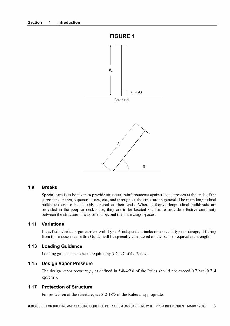
1.7.1 Section Properties of Structural Members The geometric properties of structural members may be calculated directly from the dimensions of the section and the associated effective plating (see 3-1-2/13.3 of the Rules or Section 5, Figure 3, as applicable). For structural members with angle θ (see Section 1, Figure 1) between web and associated plating not less than 75 degrees, the section modulus, web sectional area, and moment of inertia of the “standard” (θ = 90 degrees) section may be used without modification. Where the angle θ is less than 75 degrees, the sectional properties are to be directly calculated about an axis parallel to the associated plating (see Section 1, Figure 1).
For longitudinals, frames and stiffeners, the section modulus may be obtained by the following equation:
SM = αθSM90
where
αθ = 1.45 − 40.5/θ
SM90 = the section modulus at θ = 90 degrees
1.7.2 Detailed Design The detail design of internals is to follow the guidance given in 3-1-2/15 of the Rules and in 5/1.3 of this Guide.
See also Appendix 3 “Simplified Fatigue Strength Assessment”.
Section 1 Introduction
ABS GUIDE FOR BUILDING AND CLASSING LIQUEFIED PETROLEUM GAS CARRIERS WITH TYPE-A INDEPENDENT TANKS . 2006 3
FIGURE 1
θ = 90°
dw
Standard
θ
dw
1.9 Breaks
Special care is to be taken to provide structural reinforcements against local stresses at the ends of the cargo tank spaces, superstructures, etc., and throughout the structure in general. The main longitudinal bulkheads are to be suitably tapered at their ends. Where effective longitudinal bulkheads are provided in the poop or deckhouse, they are to be located such as to provide effective continuity between the structure in way of and beyond the main cargo spaces.
1.11 Variations
Liquefied petroleum gas carriers with Type-A independent tanks of a special type or design, differing from those described in this Guide, will be specially considered on the basis of equivalent strength.
1.13 Loading Guidance
Loading guidance is to be as required by 3-2-1/7 of the Rules.
1.15 Design Vapor Pressure
The design vapor pressure po as defined in 5-8-4/2.6 of the Rules should not exceed 0.7 bar (0.714 kgf/cm2).
1.17 Protection of Structure For protection of the structure, see 3-2-18/5 of the Rules as appropriate.

Section 1 Introduction
4 ABS GUIDE FOR BUILDING AND CLASSING LIQUEFIED PETROLEUM GAS CARRIERS WITH TYPE-A INDEPENDENT TANKS . 2006
1.19 Aluminum Paint Paint containing aluminum is not to be used in cargo tanks, pump rooms and cofferdams, nor in any other area where cargo vapor may accumulate, unless it has been shown by appropriate tests that the paint to be used does not increase the fire hazard.
1.21 Containment System Secondary barrier, insulation, materials, construction and testing of the cargo containment system are to comply with the applicable requirements in Section 5-8-4 of the Rules.

ABS GUIDE FOR BUILDING AND CLASSING LIQUEFIED PETROLEUM GAS CARRIERS WITH TYPE-A INDEPENDENT TANKS . 2006 5
S E C T I O N 2 Design Considerations and General Requirements
1 General Requirements
1.1 General The proposed scantlings are to comply with the requirements specified in this Guide. Owner’s extra scantlings (i.e., Owner’s specified additional thickness), as included in the vessel’s design specifications, are not be used in the evaluation. The requirements in this Guide are based on the gross scantling approach.
The requirements related to Type-A independent cargo tanks apply to only where non-corrosive cargoes are carried. If corrosive cargoes are carried in these tanks, the scantlings are to be suitably increased or an effective method of corrosion control is to be adopted.
1.3 Initial Scantling Requirements The initial thickness of plating, the section modulus of longitudinals/stiffeners, and the scantlings of main supporting structures are to be determined in accordance with Section 5. The scantlings that comply with the requirements in Section 5 are to be used for further assessment as required in the following paragraph.
1.5 Strength Assessment – Failure Modes A total strength assessment of the structures, determined on the basis of the initial strength criteria in Section 5 is to be carried out against the following three failure modes:
1.5.1 Material Yielding The calculated stress intensities are not to be greater than the yielding state limit given in Subsection 6/5 for the applicable load cases specified in Subsection 4/3.
1.5.2 Buckling and Ultimate Strength For each individual member, plate or stiffened panel, the buckling and ultimate strength is to be in compliance with the requirements specified in Subsection 6/7 for the applicable load cases specified in Subsection 4/3.
1.5.3 Fatigue The fatigue strength of structural details and welded joints in highly stressed regions, is to be analyzed in accordance with Subsection 6/9 for the applicable load cases specified in Subsection 4/5.
1.7 Structural Redundancy and Residual Strength Consideration is to be given to structural redundancy and hull girder residual strength in the early design stages.

This Page Intentionally Left Blank

ABS GUIDE FOR BUILDING AND CLASSING LIQUEFIED PETROLEUM GAS CARRIERS WITH TYPE-A INDEPENDENT TANKS . 2006 7
S E C T I O N 3 Dynamic Load Criteria
1 General
For strength assessment against the yielding and buckling failure modes, the dynamic load criteria represent the long-term extreme values for the North Atlantic, corresponding to a probability of exceedance of 10-8. For vessels serving in more severe seas, the dynamic load criteria are to be modified. These dynamic load criteria have an implied ship speed of zero knots in extreme sea conditions with exception of the impact load criteria. The ship speed used to calculate bow wave impact, bow flare slamming, flat bottom slamming, green water and cargo sloshing are to be taken as 75% of the design speed (MCR).
For strength assessment against the fatigue failure mode, the dynamic load criteria represent the characteristic values for the North Atlantic, corresponding to a probability of exceedance of 10-4. These dynamic load criteria have an implied ship speed equal to 75% of the design speed (MCR).
The following dynamic load components are to be considered in the structural evaluation of hull, cargo tanks, tank supports and chocks:
• Vertical and horizontal wave-induced bending moments
• Vertical and horizontal wave-induced shear forces
• External pressure
• Internal pressure
• Bow wave impact
• Bow flare slamming for forebody structures
• Bottom slamming for forebody structures
• Green water
• Sloshing loads
• Thermal loads
• Loads corresponding to ship deflection.
The load combination factors for the dynamic load components and dominant parameters are included in the load formulae in this Section, but their actual values are specified in Section 4.
3 Definitions
3.1 Symbols B molded breadth, in m
Cb block coefficient at the scantling draft

Section 3 Dynamic Loading Criteria
8 ABS GUIDE FOR BUILDING AND CLASSING LIQUEFIED PETROLEUM GAS CARRIERS WITH TYPE-A INDEPENDENT TANKS . 2006
D molded depth, in m
df scantling draft, in m
GM metacentric height, in m
L scantling length, in m
LBP length between perpendiculars, in m
V service speed, in knots
Vd design speed (MCR), in knots
3.3 Coordinate Systems Two sets of Cartesian coordinate systems are used to describe dynamic load criteria. When alternative coordinate systems are used, attention is to be paid to the default coordinate systems used in the dynamic load formulae.
3.3.1 Ship Coordinate System for Ship Motion and External Pressure Origin Intersection of the AP section, waterline and centerline planes.
xT Longitudinal distance from the AP to the center of the tank, in m, positive toward bow.
yT Vertical distance from the waterline to the center of the tank, in m, positive above and negative below the waterline.
zT Transverse distance from the centerline to the center of the tank, in m, positive toward starboard.
x Longitudinal distance from the AP to the external pressure point considered, in m.
xo Longitudinal distance from the AP to the reference station, in m. The reference station is the point along the vessel’s length where the wave trough or crest is located and may be taken at the mid-length of the considered tank.
3.3.2 Tank Coordinate System for Internal Pressure Origin Intersection of the vertical, horizontal and transverse planes that are tangential to
the envelope of the tank. This origin is also referred to as the zero dynamic pressure point. For example, the zero dynamic pressure point in Section 3, Figure 1 is located at the upper corner of the aft transverse bulkhead on the port side, and the forward portion of the tank on the starboard side is under high dynamic pressure and is targeted for strength assessment.
xl Longitudinal distance from the zero dynamic pressure point of the tank to the pressure point, in m, positive toward bow for a fore cargo tank structure.
yl Vertical distance from the zero dynamic pressure point of the tank to the pressure point, in m, positive downward.
zl Transverse distance from the zero dynamic pressure point of the tank to the pressure point, in m, positive toward starboard.
ale Dimensionless longitudinal acceleration, positive forward
ate Dimensionless transverse acceleration, positive starboard
ave Dimensionless vertical acceleration, positive upward

Section 3 Dynamic Loading Criteria
ABS GUIDE FOR BUILDING AND CLASSING LIQUEFIED PETROLEUM GAS CARRIERS WITH TYPE-A INDEPENDENT TANKS . 2006 9
FIGURE 1 Tank Coordinate System for Internal Pressure
zl
xl
yl
ale
ateave
Center of Tank
o (Zero Dynamic Pressure Point)
Forward
5 Vertical Wave-induced Bending Moment
The vertical wave-induced bending moment, in tf-m, may be obtained from the following equations:
Mws = −11.22 kp kcmv ks mv C1 L2B(Cb + 0.7) × 10-3 Sagging Moment
Mwh = +19.37 kp kcmv ks mv C1 L2BCb × 10-3 Hogging Moment
where
C1 = 5.1
10030075.10
−
−L 90 ≤ L < 300
= 10.75 300 ≤ L < 350
= 5.1
15035075.10
−
−L 350 ≤ L < 500
kcmv = load combination factor for design vertical wave-induced bending moment
kp = load factor for adjusting the probability of exceedance
= 1.0 for yielding and buckling strength assessment
= 0.5 for fatigue strength assessment
ks = 1.0 for yielding and buckling strength assessment
= (1.09 + 0.029V – 0.47Cb)0.5 for fatigue strength assessment
mv = distribution factor for vertical wave-induced bending moment (see Section 3, Figure 2)

Section 3 Dynamic Loading Criteria
10 ABS GUIDE FOR BUILDING AND CLASSING LIQUEFIED PETROLEUM GAS CARRIERS WITH TYPE-A INDEPENDENT TANKS . 2006
FIGURE 2 Distribution Factor for Vertical Wave-induced Bending Moment mv
0
Aftend of L
Forwardend of L
0.4 0.65 1.00.0
1.0
Distance from the aft end of L in terms of L
Dist
ribut
ion
mv
7 Horizontal Wave-induced Bending Moment
The horizontal wave-induced bending moment, in tf-m, positive (tension port) or negative (tension starboard), may be obtained from the following equation.
Mh = ±85.656 kp ks kcmhmhC1L2 D(Cb + 0.7)×10-4
where
kcmh = load combination factor for design horizontal wave-induced bending moment
kp = load factor for adjusting the probability of exceedance
= 1.0 for yielding and buckling strength assessment
= 0.5 for fatigue strength assessment
mh = distribution factor for horizontal wave-induced bending moment (see Section 3, Figure 3)
C1 and ks are as given in Subsection 3/5.
FIGURE 3 Distribution Factor for Horizontal Wave-induced Bending Moment mh
1.0
0.00.0 0.4 0.6
Distance from the aft end of L in terms of L
1.0
Dist
ribut
ion
mh
Aftend of L
Forwardend of L

Section 3 Dynamic Loading Criteria
ABS GUIDE FOR BUILDING AND CLASSING LIQUEFIED PETROLEUM GAS CARRIERS WITH TYPE-A INDEPENDENT TANKS . 2006 11
9 External Pressure
The external pressure, pe, positive toward inboard, in kgf/cm2, with waves approaching the hull from the starboard side can be expressed by the following equation at a given cross section:
pe = ρ(hs + 1.36 kp ks kcekdαC1) × 10-4 ≥ 0
where
α = 0.75 – 1.25 sin µ waterline, port = 0.2 – 0.4 sin µ + 0.1 cos µ bilge, port = 0.3 – 0.2 sin µ centerline, bottom = 0.4 – 0.1 cos µ bilge, starboard = 1.0 – 0.25 cos µ waterline, starboard
kd = ( ) ( )[ ]µµπ
cos11cos2
cos11 −+
−−− o
o kL
xxl
µ = wave heading angle, to be taken from 0° to 90° (0° for head sea, 90° for beam sea, waves approaching the hull from the starboard side)
hs = hydrostatic pressure head in still water, in m
kce = load combination factor for external pressure
kp = load factor for adjusting the probability of exceedance
= 1.0 for yielding and buckling strength assessment
= 0.5 for fatigue strength assessment
ρ = specific weight of sea water in kgf/m3
C1 and ks are as given in Subsection 3/5 and the pressure distribution factor, klo, may be taken from Section 3, Table 1 or Section 3, Figure 4. A negative combination factor, kce, signifies that the wave trough is on the starboard side.
FIGURE 4 Pressure Distribution Function klo
end of L
Distance from the aft end of L in terms of L
0.2 0.7Forwardend of L
2.5
1.5
Aft
Dist
ribut
ion
klo
1.0
1.00.00.0

Section 3 Dynamic Loading Criteria
12 ABS GUIDE FOR BUILDING AND CLASSING LIQUEFIED PETROLEUM GAS CARRIERS WITH TYPE-A INDEPENDENT TANKS . 2006
TABLE 1 klo Coefficient
[xo – (LBP – L)]/L klo [xo – (LBP – L)]/L klo [xo – (LBP – L)]/L klo 0.000 1.500 0.175 1.063 0.850 1.750 0.025 1.438 0.200 ~ 0.700 1.000 0.875 1.875 0.050 1.375 0.725 1.125 0.900 2.000 0.075 1.313 0.750 1.250 0.925 2.125 0.100 1.250 0.775 1.375 0.950 2.250 0.125 1.188 0.800 1.500 0.975 2.375 0.150 1.125 0.825 1.625 1.000 2.500
The external pressure may be calculated for the reference section at xo and the pressure variation over the length of the global finite element model may be ignored. The reference section may be taken at the mid-length of the targeted cargo tank. However, the pressure variation along the girth of the reference section is to be accounted for and can be represented by the pressure values at the following five points, as shown in Section 3, Figure 5:-
E1 waterline, port
E2 bilge, port
E3 centerline, bottom
E4 bilge, starboard
E5 waterline, starboard
A positive dynamic pressure may be assumed to vary linearly above the waterline at E1 on the port side, as illustrated in Section 3, Figure 5. The zero pressure point is defined by h1, which is equal to the dynamic pressure head or freeboard, whichever is less.
When a negative dynamic pressure is found, for example, at the waterline at E5 on the starboard side in Section 3, Figure 5, the zero pressure point can be defined by h2, which can be calculated as follows:
4E5E
5E2 pp
pdh m −
=
The negative pressure above the zero pressure point is ignored.
The external pressure on the bottom shell plating linearly varies from pressure, pE2 (bilge, port), to pressure, pE4 (bilge, starboard). dm is the draft the mid-length of the targeted cargo tank for a specific loading condition, in m.
The term “bottom shell plating” refers to the plating from the keel to the upper turn of the bilge amidships, but the upper turn of the bilge is not to be taken more than 0.2D above the baseline.

Section 3 Dynamic Loading Criteria
ABS GUIDE FOR BUILDING AND CLASSING LIQUEFIED PETROLEUM GAS CARRIERS WITH TYPE-A INDEPENDENT TANKS . 2006 13
FIGURE 5 External Pressure Calculation Points
Port Stbd
E1 E5
E4E2E3
h2
h1
11 Internal Pressure
11.1 Accelerations The accelerations acting on tanks are estimated at their center of gravity. ale, ate and ave are the maximum dimensionless accelerations (i.e., relative to the acceleration of gravity) in the longitudinal, transverse and vertical directions, respectively and they are considered as acting separately for calculation purposes. ave does not include the component due to the static weight, ate includes the component due to the static weight in the transverse direction due to rolling and ale includes the component due to the static weight in the longitudinal direction due to pitching. The following formulae are given as guidance for the components of acceleration due to ship’s motions in the North Atlantic.
Vertical acceleration:
ave = ± ao
5.122 6.045.0453.51
−
′
−+
b
T
CLx
L
Transverse acceleration:
ate = ± ao
22
6.0145.05.26.0
++
−
′+
ByKK
Lx TT
Longitudinal acceleration:
ale = ± ao AA 25.006.0 2 −+
with
A =
+−
b
T
CLyL 6.05
12007.0
where
ao = ( )
−+
L
LL
Vk p
600342.0

Section 3 Dynamic Loading Criteria
14 ABS GUIDE FOR BUILDING AND CLASSING LIQUEFIED PETROLEUM GAS CARRIERS WITH TYPE-A INDEPENDENT TANKS . 2006
kp = load factor for adjusting the probability of exceedance = 1.0 for yielding and buckling strength assessment = 0.5 for fatigue strength assessment
Tx′ = xT – (LBP – L)
K = 1.0 in general. For particular loading conditions and hull forms, determination of K according to the formula below may be necessary.
= 13GM/B, where K ≥ 1.0.
GM = metacentric height, in m
V = 10 knots for yielding and buckling strength assessment Note: The accelerations calculated from the recommended formula in IGC Code at 10 knots are
considered representative of the ship’s actual accelerations in extreme sea conditions.
= 75% of the design speed for fatigue strength assessment.
11.3 Internal Pressure for Initial Scantling Evaluation To determine the inertial forces and added pressure heads for a completely filled cargo tank, the dominating ship motion parameters induced by waves are to be calculated. The internal pressure peq resulting from the design vapor pressure po and the liquid pressure pgd, but not including effects of liquid sloshing, is to be calculated as follows:
peq = po + pgd
The internal liquid pressures are those created by the resulting acceleration of the center of gravity of the cargo due to the motions of the ship. The value of internal liquid pressure pgd resulting from combined effects of gravity and dynamic accelerations is to be calculated as follows:
pgd = ρaβZβ 10-4
Note: For initial scantling evaluation, the cargo tank pressure is to be determined based on the full load condition corresponding to the scantling draft.
where
ρ = specific weight of ballast or cargo in kgf/m3
aβ = dimensionless acceleration (i.e., relative to the acceleration of gravity), resulting from gravitational and dynamic loads, in an arbitrary direction β (see Section 3, Figure 6).
Zβ = largest liquid height (m) above the point where the pressure is to be determined, measured from the tank shell in the β direction (see Section 3, Figure 7).
Tank domes considered to be part of the accepted total tank volume should be taken into account when determining Zβ unless the total volume of tank domes Vdom does not exceed the following value:
Vdom = Vtank
−
FLFL100
where
Vtank = tank volume without any domes
FL = filling limit according to Section 5-8-15 of the Rules

Section 3 Dynamic Loading Criteria
ABS GUIDE FOR BUILDING AND CLASSING LIQUEFIED PETROLEUM GAS CARRIERS WITH TYPE-A INDEPENDENT TANKS . 2006 15
The direction which gives the maximum value (pgd)max of pgd is to be considered for the scantling requirements of plating and stiffeners of cargo tank boundaries. Where acceleration components in three directions need to be considered, an ellipsoid is to be used instead of the ellipse in Section 3, Figure 7. The above formula applies only to full tanks.
FIGURE 6 Acceleration Ellipse
CG OF TANK
AMIDSHIPS
At 0.05L from FP
Ellipses
ß
1.0
ßmax
CL
aβ = resulting acceleration (static and dynamic) in arbitrary direction βaY = transverse component of accelerationaZ = vertical component of acceleration
a ZaY
a β
FIGURE 7 Determination of Internal Pressure Heads
Zβ 3
aβ
2
Y
β
β1
Zβ 2
Zβ 1
3
Z
Note: Small tank domes not considered to be part of the accepted total volume of the cargo tank need not be considered
when determining Zβ.

Section 3 Dynamic Loading Criteria
16 ABS GUIDE FOR BUILDING AND CLASSING LIQUEFIED PETROLEUM GAS CARRIERS WITH TYPE-A INDEPENDENT TANKS . 2006
11.5 Internal Pressure Formula for Strength Assessment For finite element strength assessment, the internal pressure acting on cargo and ballast tanks corresponds to the instantaneous value when one dominant load parameter attains its maximum value. The internal pressure, pi, positive toward outboard, for a completely filled tank, in kgf/cm2, may be obtained from the following formula:
pi = ρ[(kcl ale xl + kct ate zl + kcv ave yl) + yl] × 10-4 + po
where
kcl = load combination factor for effective longitudinal acceleration
kct = load combination factor for effective transverse acceleration
kcv = load combination factor for effective vertical acceleration
ρ = specific weight of ballast or cargo in kgf/m3; for ballast water, 1025 kgf/m3 is to be used.
For a ballast tank, the design vapor pressure po is to be taken as the static pressure head corresponding to two thirds of the distance from the top of the tank to the top of the overflow.
13 Impact Loads
13.1 Impact Loads on Bow When experimental data or direct calculations are not available, the nominal wave-induced bow pressure in kgf/cm2 above the water line (LWL) in the region from the forward end to the collision bulkhead may be obtained from the following equation:
Pbij = ( ) ijijbi
ijbik LV
FaF
C γαπ sinsin515.02
2cos101045.0
22/12/1
2 +
−+
where
V = 75% of the design speed, Vd, in knots. V is not to be taken less than 10 knots.
γij = local bow angle measured from the horizontal, not to be taken less than 50°
= tan-1(tan βij/cos αij)
αij = local waterline angle measured from the centerline, see Section 3, Figure 8, not to be taken less than 35°
βij = local body plan angle measure from the horizontal, see Section 3, Figure 8, not to be taken less than 35°
Fbi = freeboard from the highest deck at side to the LWL at station i, see Section 3, Figure 8
aij = vertical distance from the LWL to WLj, see Section 3, Figure 8
Ck = 0.7 at collision bulkhead and 0.9 at 0.0125L, linear interpolation for in between
= 0.9 between 0.0125L and the FP
= 1.0 at and forward of the FP
i, j = station and waterline at the pressure calculation point.

Section 3 Dynamic Loading Criteria
ABS GUIDE FOR BUILDING AND CLASSING LIQUEFIED PETROLEUM GAS CARRIERS WITH TYPE-A INDEPENDENT TANKS . 2006 17
To assess the strength of the plating and stiffeners, a load factor of 1.1 is to be applied to the nominal pressure given above. To assess the strength of the main supporting members, a load factor of 0.71 is to be applied to the nominal pressure given above.
FIGURE 8 Definition of Bow Geometry
LWL
Fbi aij
s
WLj
bodyplanangle β
tangent line
highestdeck
CL
CL
waterline angle
WLj
tangent line
α
13.3 Bottom Slamming Pressure For a liquefied petroleum gas carrier with the heavy weather ballast draft forward less than 0.04L, bottom slamming is to be considered in the strength assessment of the flat of bottom plating forward and the associated stiffening system in the forebody region. The equivalent bottom slamming pressure for the i-th section, in kgf/cm2, may be determined by the following equations:
psi = 0.418kiωL1/2 (0.0841L + BiMRiEni) × 10-4
where
ki = 2.2 *ib /doi + α ≤ 40
ω = natural angular frequency of hull girder 2-node vertical vibration in the wet mode and the heavy weather ballast draft condition, in rad/second
= [ ]
7.30.1)3/(2.1
74752/1
33
3≥+
+ bbb dBLCBD
∆

Section 3 Dynamic Loading Criteria
18 ABS GUIDE FOR BUILDING AND CLASSING LIQUEFIED PETROLEUM GAS CARRIERS WITH TYPE-A INDEPENDENT TANKS . 2006
MRi = 0.44Ai(VL/Cb)1/2
Eni = 8.653 + 0.5 ln Bi – (0.0841L/Bi + di2)/MRi if Eni < 0, psi = 0
V = 75% of the design speed, Vd, in knots. V is not to be taken less than 10 knots.
∆b = vessel’s displacement in the heavy ballast condition, in tf
bi = half breadth at the 1/10 draft of the i-th section in the heavy ballast condition, in m
*ib = half width of flat of bottom at the i-th section, in m
db = draft amidships in the heavy ballast condition, in m
di = draft at the i-th section in the heavy ballast condition, in m
doi = 1/10 of the section draft of the i-th section in the heavy ballast condition, in m
α, Ai and Bi are as given in Section 3, Tables 2 and 3.
To assess the strength of the plating and stiffeners, a load factor of 1.1 is to be applied to the nominal pressure given above.
To assess the strength of the double bottom floors and girders, the nominal pressure uniformly distributed over the flat bottom of the foremost cargo tank may be taken as:
pnslam = ( )∑
∑
=
=− +× N
iii
N
isiii
sb
psbL
1
*
1
*
3 485.010185.1
where
N = number of floors in the double bottom of the fore cargo tank
psi = bottom slamming pressure at the i-th section, in kgf/cm2
pnslam = nominal slamming pressure for double bottom structure, in kgf/cm2
si = sum of one half of floor spacings on both sides of the i-th floor, in m
To assess the strength of the main supporting members, a load factor of 1.0 is to be applied to the nominal pressure given above.

Section 3 Dynamic Loading Criteria
ABS GUIDE FOR BUILDING AND CLASSING LIQUEFIED PETROLEUM GAS CARRIERS WITH TYPE-A INDEPENDENT TANKS . 2006 19
TABLE 2 α Coefficient
bi/doi α 1.00 0.00 1.50 9.00 2.00 11.75 2.50 14.25 3.00 16.50 3.50 18.50 4.00 20.25 5.00 22.00 6.00 23.75 7.00 24.50 7.50 24.75 25.0 24.75
Linear interpolation may be used for intermediate values.
TABLE 3 Ai and Bi Coefficients
Section Location Ai Bi -0.05L 1.25 0.3600
FP 1.00 0.4000 0.05L 0.80 0.4375 0.10L 0.62 0.4838 0.15L 0.47 0.5532 0.20L 0.33 0.6666 0.25L 0.22 0.8182 0.30L 0.22 0.8182
Linear interpolation may be used for intermediate values.
13.5 Bowflare Slamming For vessels possessing bowflare and having a shape parameter Ar greater than 21 m, in the forebody region, bowflare slamming loads are to be considered for assessing the strength of the side plating and the associated stiffening system in the forebody region of the vessel at its scantling draft.
Ar = the maximum value of Ari in the forebody region. Ari = bowflare shape parameter at a station i forward of the quarter length, up to the FP
of the vessel, to be determined between the load waterline (LWL) and the upper deck/forecastle. Bowflare shape parameter Ari is to be calculated for five stations
=
2/12
1
2
1
1 1
+
∑∑
∑
=
=
=
j
jn
jjn
jj
n
jj
bs
bs
b
, j = 1 … n, n ≥ 4

Section 3 Dynamic Loading Criteria
20 ABS GUIDE FOR BUILDING AND CLASSING LIQUEFIED PETROLEUM GAS CARRIERS WITH TYPE-A INDEPENDENT TANKS . 2006
where
n = number of segments
bj = local change (increase) in beam for the j-th segment at station i (see Section 3, Figure 9)
sj = local change (increase) in freeboard up to the highest deck for the j-th segment at station i forward (see Section 3, Figure 9).
When experimental data or direct calculation is not available, the nominal bowflare slamming pressure in kgf/cm2 may be determined by the following equations:
Pij = Poij or Pbij as defined below, whichever is greater
Poij = 0.1(9MRi − 2ijh )2/3
Pbij = 0.01045[39.2 + Kij Bi MRi(1 + Eni)]
where
Eni = 8.653 + 0.5 ln Bi – 2ijh /MRi, if Eni < 0, Pbij = 0
MRi = 0.44Ai(VL/Cb)1/2
V = 75% of the design speed, Vd, in knots. V is not to be taken less than 10 knots.
hij = vertical distance measured from the LWL at station i to the waterline WLj on the bowflare. The value of hij is not to be taken less than 2.0 m.
Kij =
+
− 2/1
2/32/122
5.014.3tan
190
Ri
ij
ijij
Riij
ij Ml
hbMβ
βcos γ
bij = local half beam of WLj at station i.
lij = longitudinal distance of WLj at station i measured from amidships.
βij = local body plan angle measured from the horizontal, in degrees, need not be taken less than 35 degrees, see Section 3, Figure 9
γ = ship stem angle at the centerline measured from the horizontal, Section 3, Figure 10, in degrees, not to be taken greater than 75 degrees.
Ai and Bi are as given in Section 3, Table 3.
For performing structural analyses to determine overall responses of the hull structures, the spatial distribution of instantaneous bowflare slamming pressures on the forebody region of the hull may be expressed by multiplying the calculated maximum bowflare slamming pressures, Pij, at forward ship stations by a factor of 0.71 for the region between the stem and 0.3L from the FP.

Section 3 Dynamic Loading Criteria
ABS GUIDE FOR BUILDING AND CLASSING LIQUEFIED PETROLEUM GAS CARRIERS WITH TYPE-A INDEPENDENT TANKS . 2006 21
FIGURE 9 Definition of Bowflare Geometry for Bowflare Shape Parameter
highest deck
βij
(body plan angle)
b1
s1
LWL
cent
erlin
e
b2
s2
b3s3
s4
b4
FIGURE 10 Ship Stem Angle, γ
Stem Angle γ
F.P.

Section 3 Dynamic Loading Criteria
22 ABS GUIDE FOR BUILDING AND CLASSING LIQUEFIED PETROLEUM GAS CARRIERS WITH TYPE-A INDEPENDENT TANKS . 2006
13.7 Green Water The nominal green water pressure imposed on the deck in the region from the FP to 0.25L aft, including the extension beyond the FP, may be calculated at the reference section:
pgi =
2/12/1
44.02.0
−
bi
bi F
CVLA , not to be less than 0.21 kgf/cm2
where
V = 75% of the design speed, Vd, in knots. V is not to be taken less than 10 knots.
Fbi = freeboard from the highest deck at side to the load waterline (LWL) at station i, see Section 3, Figure 8
Ai is given in Section 3, Table 3.
13.9 Sloshing Loads Except for tanks that are situated wholly within the double side or double bottom, the natural periods of liquid motions are to be examined to assess the possibility of excessive liquid sloshing against boundary structures for all cargo tanks which will be partially filled between 0.5hl (or 0.1h, if lesser) and 0.9h (hl and h are as defined in Section 3, Figure 11). For each of the anticipated loading conditions, the “critical” filling levels of the tank are to be avoided so that the natural periods of fluid motions in the longitudinal and transverse directions will not synchronize with the natural periods of the vessel’s pitch and roll motions, respectively. The natural periods of the fluid motions in the tank, for each of the anticipated filling levels, are to be at least 20% greater or smaller than that of the relevant ship’s motion.
The natural period of the fluid motion may be approximated by the following equations:
Tx = (l)1/2/k seconds in the longitudinal direction
Ty = (bf)1/2/k seconds in the transverse direction
where
l = length of the tank, as defined in Section 3, Figure 11, in m
bf = breadth of the liquid surface at do, as defined in Section 3, Figure 11, in m
k = [(tanh H1)/(4π/g)]1/2
H1 = π do/l or π do/bf
do = filling depth, as defined in Section 3, Figure 11, in m
g = acceleration of gravity = 9.8 m/sec2
The natural periods given below for pitch and roll of the vessel, Tp and Tr, using the actual draft and GM, if available, may be used for this purpose. In absence of these data, the vessel’s draft may be taken as 2/3df.
The pitch natural period:
Tp = 3.5 ib dC seconds
where
di = draft amidships for the relevant loading conditions

Section 3 Dynamic Loading Criteria
ABS GUIDE FOR BUILDING AND CLASSING LIQUEFIED PETROLEUM GAS CARRIERS WITH TYPE-A INDEPENDENT TANKS . 2006 23
The roll natural motion period:
Tr = 2 kr/GM0.5 seconds
where
kr = roll radius of gyration, in m, and may be taken as 0.35B for full load conditions and 0.45B for ballast conditions.
GM = metacentric height, in m, to be taken as:
= GM (full) for full draft
= 1.5 GM (full) for 3/4 df
= 2.0 GM (full) for 2/3 df
GM (full) = metacentric height for fully loaded condition
= 0.12B in case GM (full) is not available.
If the “critical” filling levels of the tank cannot be avoided, the tank is to have a non-tight bulkhead (i.e., swash bulkhead) to eliminate the possibility of resonance. The non-tight bulkhead may be waived if it can be demonstrated through the application of model experiments or numerical simulation using three-dimensional flow analysis that sloshing impacts do not occur.
Alternatively, the tank boundary structures can also be designed to withstand liquid sloshing. The design sloshing pressures are to be explicitly considered in the scantling requirements of cargo tank plating and stiffeners. In addition, additional sloshing load cases are to be included in the structural analysis of the main supporting members of cargo tanks. Sloshing loads may also be determined by model experiments. Methodology and procedures of tests and measurements are to be fully documented and referenced. They are to be submitted for review by the Bureau.
FIGURE 11 Definition of Tank Geometry
lbt
bf
bdo
h
hu
hl
15 Thermal Loads
Transient thermal loads during cooling down periods are to be considered for cargo tanks intended for cargo temperatures below -55°C.
Stationary thermal loads are to be considered for tanks where design supporting arrangement and operating temperature may give rise to significant thermal stresses.

This Page Intentionally Left Blank

ABS GUIDE FOR BUILDING AND CLASSING LIQUEFIED PETROLEUM GAS CARRIERS WITH TYPE-A INDEPENDENT TANKS . 2006 25
S E C T I O N 4 Standard Design Load Cases
1 Symbols
df scantling draft, in m
dflood draft at the mid-tank for the flooded condition
db ballast draft at the middle of foremost cargo tank, in m
Df imaginary freeboard depth, in m
kce load combination factor for external pressure
kcl load combination factor for effective longitudinal acceleration
kcmh load combination factor for horizontal wave-induced bending moment
kcmv load combination factor for vertical wave-induced bending moment
kct load combination factor for effective transverse acceleration
kcv load combination factor for effective vertical acceleration
µ wave heading angle, to be taken from 0° to 90° (0° for head sea, 90° for beam sea, waves approaching the hull from the starboard side)
3 Standard Design Load Cases for Yielding and Buckling Strength Assessment
To assess the yielding and buckling strength of hull and cargo tank structures, the standard design load cases described in this Section are to be analyzed. These load cases can be categorized into the following groups:-
• Dynamic sea load cases (LC1 ~ LC9 in Section 4, Table 1)
• Port condition load case (LC10 in Section 4, Table 2)
• Flooded load case for transverse bulkhead (LC11 in Section 4, Table 2)
• Accidental load cases for supports and chocks (LC12 ~ LC15 in Section 4, Table 2)
For forebody hull and cargo tank structures, a design load case for bottom slamming is also to be considered. Additional load cases may be required, as warranted.

Section 4 Standard Design Load Cases
26 ABS GUIDE FOR BUILDING AND CLASSING LIQUEFIED PETROLEUM GAS CARRIERS WITH TYPE-A INDEPENDENT TANKS . 2006
Section 4, Figure 1 shows the direction of the inertia load due to acceleration. The loading patterns are shown in Section 4, Figure 2. For each dynamic sea load case (LC1 to LC9), the load combination factors are specified for individual dynamic load components and motion parameters in Section 4, Table 1. The waves approach the vessel from the starboard side. If the hull structure is unsymmetrical with respect to the vessel’s centerline, additional load cases mirroring those of the unsymmetrical load cases in Section 4, Table 1 are to be analyzed. The dominant load parameter for each dynamic sea load case corresponds to a probability of exceedance of 10-8, while the load combination factors for other load parameters represent phasing between all the load parameters.
The standard load cases in Section 4, Tables 1 and 2 are specified for the midship finite element model. For the forebody finite element model, tanks forward of the collision bulkhead may be assumed empty in the standard load cases. Likewise, for the aftbody finite element model, tanks aft the hull transverse bulkhead bordering the aftmost cargo tank may be assumed empty in the standard load cases.
5 Standard Design Load Cases for Fatigue Strength Assessment
To assess the critical details of the hull, cargo tanks and supporting structures, the accumulative fatigue damage may be calculated from the vessel operating in full cargo and ballast loading conditions. For each loading condition, eight dynamic sea load cases are to be analyzed to determine the stresses at critical details. These load cases are specified in Section 4, Tables 3 and 4. The stress ranges to be used for the accumulative fatigue damage are to be calculated from the following four pairs of the load cases:-
• Load Cases 1 and 2 for maximum vertical bending moment range
• Load Cases 3 and 4 for maximum local pressure range
• Load Cases 5 and 6 for maximum transverse acceleration range
• Load Cases 7 and 8 for maximum horizontal bending moment range.
The dominant load parameter for each dynamic sea load case corresponds to a probability of exceedance of 10-4, while the load combination factors for other load parameters represent phasing between all the load parameters.
The standard load cases in Section 4, Tables 3 and 4 are specified for the midship finite element model. For the forebody finite element model, tanks forward of the collision bulkhead may be assumed empty in the standard load cases. Likewise, for the aftbody finite element model, tanks aft the hull transverse bulkhead bordering the aftmost cargo tank may be assumed empty in the standard load cases.

TAB
LE 1
St
anda
rd D
esig
n Lo
ad C
ases
for Y
ield
ing
and
Buc
klin
g St
reng
th A
sses
smen
t (L
oad
Com
bina
tion
Fact
ors
for D
ynam
ic L
oad
Com
pone
nts)
LC
1
LC 2
LC
3
LC 4
LC
5
LC 6
LC
7
LC 8
LC
9
Dom
inan
t Loa
d Pa
ram
eter
m
axim
um
sagg
ing
BM
m
axim
um
hogg
ing
BM
m
axim
um
inte
rnal
pr
essu
re
max
imum
ex
tern
al
pres
sure
max
imum
in
tern
al
pres
sure
max
imum
ho
rizon
tal
BM
Max
imum
ho
rizon
tal
BM
max
imum
in
tern
al
pres
sure
flat b
otto
m
slam
min
g
Wav
e H
eadi
ng (µ
) 0°
hea
d 0°
hea
d 0°
hea
d 0°
hea
d 90
° bea
m
60° o
bliq
ue
60° o
bliq
ue
0° h
ead
0° h
ead
Dra
ft (d
m)
d f
d f
d f
d f
3/4d
f 3/
4df
d f
d b
d b
Exte
rnal
Pre
ssur
e k c
e -0
.50
0.50
-0
.50
1.00
1.
00
-0.5
0 1.
00
-0.5
0 N
/A
Long
itudi
nal A
ccel
erat
ion
k cl
0.00
0.
00
0.00
0.
60
0.00
-0
.40
0.40
0.
00
0.00
Vert
ical
Acc
eler
atio
n k c
v 0.
50
-0.5
0 1.
00
-0.8
0 -0
.60
0.60
-0
.60
1.00
-0
.50
Tran
sver
se A
ccel
erat
ion
k ct
N/A
N
/A
N/A
N
/A
0.80
-0
.70
0.70
N
/A
N/A
Ve
rtic
al B
M k
cmv
1.00
sagg
ing
1.00
hog
ging
0.
70 sa
ggin
g 0.
70 h
oggi
ng
0.30
hog
ging
0.
40 sa
ggin
g 0.
40 h
oggi
ng
0.70
sagg
ing
N/A
H
oriz
onta
l BM
kcm
h N
/A
N/A
N
/A
N/A
0.
30 p
ort (
+)
1.00
por
t (-)
1.
00 p
ort (
+)
N/A
N
/A
Fric
tiona
l Coe
ffici
ent
N/A
N
/A
N/A
N
/A
0.10
0.
10
N/A
N
/A
N/A
Not
es
1 LC
9 is
the
botto
m sl
amm
ing
load
cas
e an
d on
ly a
pplic
able
to fo
rebo
dy h
ull a
nd c
argo
tank
stru
ctur
es.
2 po
rt (+
) and
por
t (-)
repr
esen
ts th
e po
rt si
de o
f the
hul
l stru
ctur
e is
in te
nsio
n an
d co
mpr
essi
on, r
espe
ctiv
ely.
3 Th
e fr
ictio
nal c
oeff
icie
nt in
Sec
tion
4, T
able
1 f
or L
C5
and
LC6
is th
e re
pres
enta
tive
valu
e fo
r th
e gl
obal
fin
ite e
lem
ent m
odel
. For
the
fine
mes
h fin
ite e
lem
ent
mod
els r
epre
sent
ing
indi
vidu
al su
ppor
ts o
r cho
cks,
the
fric
tiona
l coe
ffic
ient
is to
be
take
n as
0.3
. Alte
rnat
ivel
y, th
e fr
ictio
nal c
oeff
icie
nt m
ay b
e de
term
ined
from
the
mea
sure
men
t. Th
e de
tails
of t
he su
ppor
t bea
ring
mat
eria
ls, m
easu
rem
ent p
roce
dure
and
mea
sure
men
t dat
a ar
e to
be
subm
itted
for A
BS
revi
ew.
Section 4 Standard Design Load Cases
ABS GUIDE FOR BUILDING AND CLASSING LIQUEFIED PETROLEUM GAS CARRIERS WITH TYPE-A INDEPENDENT TANKS . 2006 27

TAB
LE 2
St
anda
rd D
esig
n Lo
ad C
ases
for Y
ield
ing
and
Buc
klin
g St
reng
th A
sses
smen
t (L
oad
Com
bina
tion
Fact
ors
for P
ort a
nd A
ccid
enta
l Loa
d C
ases
)
LC
10
LC 1
1 LC
12
LC 1
3 LC
14
LC 1
5 D
omin
ant L
oad
Para
met
er
port
cond
ition
on
e si
de
load
ed
flood
ed
cond
ition
(tr
ansv
erse
bu
lkhe
ad)
flood
ed
cond
ition
(a
nti-f
loat
ch
ocks
)
colli
sion
co
nditi
on
(for
war
d)
colli
sion
co
nditi
on
(aftw
ard)
30° s
tatic
he
el
Dra
ft (d
m)
1/2
d f
d flo
od o
r 0.8
D f
d f
N/A
N
/A
d f
Fric
tion
Coe
ffici
ent
N/A
N
/A
0.10
0.
10
0.10
0.
10
Long
itudi
nal I
nert
ia L
oad
N
/A
N/A
N
/A
0.50
g 0.
25g
N/A
Ve
rtic
al In
ertia
Loa
d
1.00
g N
/A
N/A
1.
00g
1.00
g 0.
87g
Tran
sver
se In
ertia
Loa
d
N/A
N
/A
N/A
N
/A
N/A
0.
50g
Vert
ical
Stil
l Wat
er B
M
N/A
N
/A
N/A
N
/A
N/A
N
/A
Not
es
1 Th
e fr
ictio
nal c
oeff
icie
nt in
Sec
tion
4, T
able
2 f
or L
C12
and
LC
15 is
the
repr
esen
tativ
e va
lue
for
the
glob
al f
inite
el
emen
t m
odel
. For
the
fin
e m
esh
finite
ele
men
t m
odel
s re
pres
entin
g in
divi
dual
sup
ports
or
choc
ks, t
he f
rictio
nal
coef
ficie
nt is
to b
e ta
ken
as 0
.3. A
ltern
ativ
ely,
the
fric
tiona
l coe
ffic
ient
may
be
dete
rmin
ed f
rom
the
mea
sure
men
t. Th
e de
tails
of
the
supp
ort b
earin
g m
ater
ials
, mea
sure
men
t pro
cedu
re a
nd m
easu
rem
ent d
ata
are
to b
e su
bmitt
ed f
or
AB
S re
view
.
2 Fo
r LC
10, a
ccou
nt is
to ta
ken
of a
n in
crea
se o
f vap
or p
ress
ure
in p
ort c
ondi
tion.
Thi
s lo
ad c
ase
may
be
omitt
ed, i
f the
pi
ping
sys
tem
s ar
e de
sign
ed t
o en
sure
tha
t th
e ca
rgoe
s on
bot
h si
des
of t
he c
ente
rline
bul
khea
d ca
n be
loa
ded
or
disc
harg
ed a
t the
sam
e ra
te.
Section 4 Standard Design Load Cases
28 ABS GUIDE FOR BUILDING AND CLASSING LIQUEFIED PETROLEUM GAS CARRIERS WITH TYPE-A INDEPENDENT TANKS . 2006

TAB
LE 3
St
anda
rd D
esig
n Lo
ad C
ases
for F
atig
ue S
tren
gth
Ass
essm
ent
(Loa
d C
ombi
natio
n Fa
ctor
s fo
r Dyn
amic
Loa
d C
ompo
nent
s fo
r Ful
l Car
go L
oadi
ng C
ondi
tion)
Load
Cas
e Pa
ir
LC1
& L
C 2
LC
3 &
LC
4
LC 5
& L
C 6
LC
7 &
LC
8
Dom
inan
t Loa
d Pa
ram
eter
m
axim
um v
ertic
al
be
ndin
g m
omen
t ran
ge
max
imum
loca
l
pr
essu
re ra
nge
max
imum
loca
l
pr
essu
re ra
nge
max
imum
hor
izon
tal
be
ndin
g m
omen
t ran
ge
Wav
e H
eadi
ng (µ
) 0°
hea
d 0°
hea
d 90
° bea
m
60° o
bliq
ue
Loca
l Pre
ssur
e Lo
ad C
ase
LC 1
LC
2
LC 3
LC
4
LC 5
LC
6
LC 7
LC
8
Dra
ft (d
m)
d f
d f
d f
d f
d f
d f
d f
d f
Exte
rnal
Pre
ssur
e k c
e -0
.50
0.50
-0
.50
1.00
-0
.50
1.00
-0
.50
1.00
Long
itudi
nal A
ccel
erat
ion
k cl
0.00
0.
00
0.00
0.
00
0.00
0.
00
-0.4
0 0.
40
Vert
ical
Acc
eler
atio
n k c
v 0.
50
-0.5
0 1.
00
-1.0
0 0.
60
-0.6
0 0.
60
-0.6
0 Tr
ansv
erse
Acc
eler
atio
n k c
t N
/A
N/A
N
/A
N/A
-0
.80
0.80
-0
.70
0.70
Vert
ical
BM
Loa
d C
ase
100%
Rul
e V
ertic
al
BM
Ran
ge
70%
Rul
e V
ertic
al
BM
Ran
ge
30%
Rul
e V
ertic
al
BM
Ran
ge
40%
Rul
e V
ertic
al
BM
Ran
ge
Hor
izon
tal B
M L
oad
Cas
e N
/A
N/A
30
% R
ule
Hor
izon
tal
B
M R
ange
10
0% R
ule
Hor
izon
tal
B
M R
ange
Not
es
1 R
ule
verti
cal b
endi
ng m
omen
t ran
ge =
|Mw
s - M
wh|
(s
ee S
ubse
ctio
n 3/
5 fo
r Mw
s and
Mw
h)
2 R
ule
horiz
onta
l ben
ding
mom
ent r
ange
= 2
× M
h
(see
Sub
sect
ion
3/7
for M
h)
3 Fo
r ea
ch l
oad
case
pai
r, th
e st
ress
ran
ge d
ue t
o lo
cal
pres
sure
is
the
diff
eren
ce b
etw
een
the
stre
ss v
alue
s fo
r Lo
cal
Pres
sure
Loa
d C
ases
. Fo
r ex
ampl
e, fo
r Loa
d C
ase
Pair
LC1
& L
C2,
the
stre
ss ra
nge
due
to lo
cal p
ress
ure
is th
e di
ffer
ence
bet
wee
n th
e st
ress
val
ues f
or L
C1
and
LC2.
4
For e
ach
load
cas
e pa
ir, th
e st
ress
rang
e is
the
sum
of t
he a
bsol
ute
stre
ss ra
nge
valu
es d
ue to
Ver
tical
BM
, Hor
izon
tal B
M a
nd L
ocal
Pre
ssur
e Lo
ad
Cas
es.
5 To
acc
ount
for t
he m
ean
stre
ss e
ffec
t on
the
fatig
ue d
amag
e, th
e m
ean
stre
ss le
vel c
an b
e de
term
ined
usi
ng th
e st
atic
load
s for
the
load
ing
cond
ition
. 6
For t
he g
loba
l fin
ite e
lem
ent m
odel
, the
fric
tiona
l coe
ffic
ient
nee
d no
t be
cons
ider
ed. F
or th
e fin
e m
esh
finite
ele
men
t mod
els
repr
esen
ting
supp
orts
or
cho
cks,
the
fric
tiona
l coe
ffic
ient
is to
be
take
n as
0.3
. Alte
rnat
ivel
y, th
e fr
ictio
nal c
oeff
icie
nt m
ay b
e ta
ken
from
the
mea
sure
men
t. Th
e de
tails
of
the
supp
ort b
earin
g m
ater
ials
, mea
sure
men
t pro
cedu
re a
nd m
easu
rem
ent d
ata
are
to b
e su
bmitt
ed fo
r AB
S re
view
.
dfPort
Stb
dP
rofil
eP
lan
C.L
Section 4 Standard Design Load Cases
ABS GUIDE FOR BUILDING AND CLASSING LIQUEFIED PETROLEUM GAS CARRIERS WITH TYPE-A INDEPENDENT TANKS . 2006 29

TAB
LE 4
St
anda
rd D
esig
n Lo
ad C
ases
for F
atig
ue S
tren
gth
Ass
essm
ent
(Loa
d C
ombi
natio
n Fa
ctor
s fo
r Dyn
amic
Loa
d C
ompo
nent
s fo
r Bal
last
Loa
ding
Con
ditio
n)
Lo
ad C
ase
Pair
LC
1 &
LC
2
LC 3
& L
C 4
LC
5 &
LC
6
LC 7
& L
C 8
Dom
inan
t Loa
d Pa
ram
eter
m
axim
um v
ertic
al
be
ndin
g m
omen
t ran
ge
max
imum
loca
l
pr
essu
re ra
nge
max
imum
loca
l
pr
essu
re ra
nge
max
imum
hor
izon
tal
be
ndin
g m
omen
t ran
ge
Wav
e H
eadi
ng (µ
) 0°
hea
d 0°
hea
d 90
° bea
m
60° o
bliq
ue
Loca
l Pre
ssur
e Lo
ad C
ase
LC 1
LC
2
LC 3
LC
4
LC 5
LC
6
LC 7
LC
8
Dra
ft (d
m)
d b
d b
d b
d b
d b
d b
d b
d b
Exte
rnal
Pre
ssur
e k c
e -0
.50
0.50
-0
.50
1.00
-0
.50
1.00
-0
.50
1.00
Long
itudi
nal A
ccel
erat
ion
k cl
0.00
0.
00
0.00
0.
00
0.00
0.
00
-0.4
0 0.
40
Vert
ical
Acc
eler
atio
n k c
v 0.
50
-0.5
0 1.
00
-1.0
0 0.
60
-0.6
0 0.
60
-0.6
0 Tr
ansv
erse
Acc
eler
atio
n k c
t N
/A
N/A
N
/A
N/A
-0
.80
0.80
-0
.70
0.70
Vert
ical
BM
Loa
d C
ase
100%
Rul
e V
ertic
al
BM
Ran
ge
70%
Rul
e V
ertic
al
BM
Ran
ge
30%
Rul
e V
ertic
al
BM
Ran
ge
40%
Rul
e V
ertic
al
B
M R
ange
Hor
izon
tal B
M L
oad
Cas
e N
/A
N/A
30
% R
ule
Hor
izon
tal
B
M R
ange
10
0% R
ule
Hor
izon
tal
B
M R
ange
Not
es
1 R
ule
verti
cal b
endi
ng m
omen
t ran
ge =
|Mw
s - M
wh|
(s
ee S
ubse
ctio
n 3/
5 fo
r Mw
s and
Mw
h)
2 R
ule
horiz
onta
l ben
ding
mom
ent r
ange
= 2
× M
h
(see
Sub
sect
ion
3/7
for M
h)
3 Fo
r ea
ch l
oad
case
pai
r, th
e st
ress
ran
ge d
ue t
o lo
cal
pres
sure
is
the
diff
eren
ce b
etw
een
the
stre
ss v
alue
s fo
r Lo
cal
Pres
sure
Loa
d C
ases
. Fo
r ex
ampl
e, fo
r Loa
d C
ase
Pair
LC1
& L
C2,
the
stre
ss ra
nge
due
to lo
cal p
ress
ure
is th
e di
ffer
ence
bet
wee
n th
e st
ress
val
ues f
or L
C1
and
LC2.
4
For e
ach
load
cas
e pa
ir, th
e st
ress
rang
e is
the
sum
of t
he a
bsol
ute
stre
ss ra
nge
valu
es d
ue to
Ver
tical
BM
, Hor
izon
tal B
M a
nd L
ocal
Pre
ssur
e Lo
ad
Cas
es.
5 To
acc
ount
for t
he m
ean
stre
ss e
ffec
t on
the
fatig
ue d
amag
e, th
e m
ean
stre
ss le
vel c
an b
e de
term
ined
usi
ng th
e st
atic
load
s for
the
load
ing
cond
ition
. 6
For t
he g
loba
l fin
ite e
lem
ent m
odel
, the
fric
tiona
l coe
ffic
ient
nee
d no
t be
cons
ider
ed. F
or th
e fin
e m
esh
finite
ele
men
t mod
els
repr
esen
ting
supp
orts
or
cho
cks,
the
fric
tiona
l coe
ffic
ient
is to
be
take
n as
0.3
. Alte
rnat
ivel
y, th
e fr
ictio
nal c
oeff
icie
nt m
ay b
e ta
ken
from
the
mea
sure
men
t. Th
e de
tails
of
the
supp
ort b
earin
g m
ater
ials
, mea
sure
men
t pro
cedu
re a
nd m
easu
rem
ent d
ata
are
to b
e su
bmitt
ed fo
r AB
S re
view
.
dBPor
tS
tbd
Pro
file
Pla
n
C.L
Section 4 Standard Design Load Cases
30 ABS GUIDE FOR BUILDING AND CLASSING LIQUEFIED PETROLEUM GAS CARRIERS WITH TYPE-A INDEPENDENT TANKS . 2006

FIG
UR
E 1
Dire
ctio
n of
Inte
rnal
Pre
ssur
e du
e to
Acc
eler
atio
n
z
TRA
NS
. BH
D.
+ Lo
ngitu
dina
l Acc
el.
x
Z (S
tbd
Sid
e)
Pla
n
TRA
NS
. BH
D.
Y(V
ertic
al)
SW
AS
H B
HD
.
X(F
orw
ard)
SW
AS
H B
HD
.
xz+
Ver
ical
Acc
el.
Pla
n
Sect
ion
+ Tr
ansv
erse
Acc
el.
Section 4 Standard Design Load Cases
ABS GUIDE FOR BUILDING AND CLASSING LIQUEFIED PETROLEUM GAS CARRIERS WITH TYPE-A INDEPENDENT TANKS . 2006 31

Section 4 Standard Design Load Cases
32 ABS GUIDE FOR BUILDING AND CLASSING LIQUEFIED PETROLEUM GAS CARRIERS WITH TYPE-A INDEPENDENT TANKS . 2006
FIGURE 2 Loading Pattern (Yielding and Buckling Strength Assessment)
Load Case 1 Dominant Load Parameter maximum sagging BM Wave Heading (µ) 0° head Draft (dm) df External Pressure kce -0.50
Longitudinal Acceleration kcl 0.00
Vertical Acceleration kcv 0.50 Transverse Acceleration kct N/A Vertical BM kcmv 1.00 sagging Horizontal BM kcmh N/A Friction Coefficient N/A
PlanPort
df
ProfileStbd
MSW+MWV
C.L
Load Case 2
Dominant Load Parameter maximum hogging BM Wave Heading (µ) 0° head Draft (dm) df External Pressure kce 0.50
Longitudinal Acceleration kcl 0.00
Vertical Acceleration kcv -0.50 Transverse Acceleration kct N/A Vertical BM kcmv 1.00 hogging Horizontal BM kcmh N/A Friction Coefficient N/A
df
Port
MSW+MWV
StbdProfile
C.L
Plan

Section 4 Standard Design Load Cases
ABS GUIDE FOR BUILDING AND CLASSING LIQUEFIED PETROLEUM GAS CARRIERS WITH TYPE-A INDEPENDENT TANKS . 2006 33
FIGURE 2 (continued) Loading Pattern (Yielding and Buckling Strength Assessment)
Load Case 3 Dominant Load Parameter maximum internal pressure Wave Heading (µ) 0° head Draft (dm) df External Pressure kce -0.50
Longitudinal Acceleration kcl 0.00
Vertical Acceleration kcv 1.00 Transverse Acceleration kct N/A Vertical BM kcmv 0.70 sagging Horizontal BM kcmh N/A Friction Coefficient N/A
df
Port
MSW+MWV
StbdProfile Plan
C.L
Load Case 4 Dominant Load Parameter maximum external pressure Wave Heading (µ) 0° head Draft (dm) df External Pressure kce 1.00
Longitudinal Acceleration kcl 0.60
Vertical Acceleration kcv -0.80 Transverse Acceleration kct N/A Vertical BM kcmv 0.70 hogging Horizontal BM kcmh N/A Friction Coefficient N/A
df
MSW+0.7MWV
C.L
Port StbdProfile Plan

Section 4 Standard Design Load Cases
34 ABS GUIDE FOR BUILDING AND CLASSING LIQUEFIED PETROLEUM GAS CARRIERS WITH TYPE-A INDEPENDENT TANKS . 2006
FIGURE 2 (continued) Loading Pattern (Yielding and Buckling Strength Assessment)
Load Case 5 Dominant Load Parameter maximum transverse acceleration Wave Heading (µ) 90° beam Draft (dm) 3/4df External Pressure kce 1.00
Longitudinal Acceleration kcl 0.00
Vertical Acceleration kcv -0.60 Transverse Acceleration kct 0.80 Vertical BM kcmv 0.30 hogging Horizontal BM kcmh 0.30 port (+) Friction Coefficient 0.10
PlanStbd
3/4 df
Port
MSW+0.3MWV
Profile
0.3MH
C.L
Load Case 6 Dominant Load Parameter maximum horizontal BM Wave Heading (µ) 60° oblique Draft (dm) 3/4df
External Pressure kce -0.50
Longitudinal Acceleration kcl -0.40
Vertical Acceleration kcv 0.60 Transverse Acceleration kct -0.70 Vertical BM kcmv 0.40 sagging Horizontal BM kcmh 1.00 port (-) Friction Coefficient 0.10
3/4 df
MSW+0.4MWV MH
C.L
PlanPort Stbd
Profile

Section 4 Standard Design Load Cases
ABS GUIDE FOR BUILDING AND CLASSING LIQUEFIED PETROLEUM GAS CARRIERS WITH TYPE-A INDEPENDENT TANKS . 2006 35
FIGURE 2 (continued) Loading Pattern (Yielding and Buckling Strength Assessment)
Load Case 7 Dominant Load Parameter maximum horizontal BM Wave Heading (µ) 60° oblique Draft (dm) df
External Pressure kce 1.00
Longitudinal Acceleration kcl 0.40
Vertical Acceleration kcv -0.60 Transverse Acceleration kct 0.70 Vertical BM kcmv 0.40 hogging Horizontal BM kcmh 1.00 port (+) Friction Coefficient N/A
StbdPort
df
Profile
C.L
MSW+0.4MWV MH
Plan
Load Case 8 Dominant Load Parameter maximum internal pressure Wave Heading (µ) 0° head Draft (dm) db
External Pressure kce -0.50
Longitudinal Acceleration kcl 0.00
Vertical Acceleration kcv 1.00 Transverse Acceleration kct N/A Vertical BM kcmv 0.70 sagging Horizontal BM kcmh N/A Friction Coefficient N/A
dB
Port
MSW+0.7MWV
ProfileStbd
Plan
C.L

Section 4 Standard Design Load Cases
36 ABS GUIDE FOR BUILDING AND CLASSING LIQUEFIED PETROLEUM GAS CARRIERS WITH TYPE-A INDEPENDENT TANKS . 2006
FIGURE 2 (continued) Loading Pattern (Yielding and Buckling Strength Assessment)
Load Case 9 Dominant Load Parameter flat bottom slamming Wave Heading (µ) 0° head Draft (dm) db
External Pressure kce N/A
Longitudinal Acceleration kcl 0.00
Vertical Acceleration kcv -0.50 Transverse Acceleration kct N/A Vertical BM kcmv N/A Horizontal BM kcmh N/A Friction Coefficient N/A
Load Case 10 Dominant Load Parameter port condition one side loaded Draft (dm) 1/2 df Friction Coefficient N/A Longitudinal Inertia Load N/A Vertical Inertia Load 1.00g Transverse Inertia Load N/A Vertical Still Water BM N/A
0.5 df
PortProfile
Stbd
C.L
Plan

Section 4 Standard Design Load Cases
ABS GUIDE FOR BUILDING AND CLASSING LIQUEFIED PETROLEUM GAS CARRIERS WITH TYPE-A INDEPENDENT TANKS . 2006 37
FIGURE 2 (continued) Loading Pattern (Yielding and Buckling Strength Assessment)
Load Case 11 Dominant Load Parameter flooded condition (transverse bulkhead) Draft (dm) dflood or 0.8D f Friction Coefficient N/A Longitudinal Inertia Load N/A Vertical Inertia Load N/A Transverse Inertia Load N/A Vertical Still Water BM N/A
Port StbdProfile Plan
C.L
Load Case 12 Dominant Load Parameter flooded condition (anti-float chocks) Draft (dm) df Friction Coefficient 0.10 Longitudinal Inertia Load N/A Vertical Inertia Load N/A Transverse Inertia Load N/A Vertical Still Water BM N/A
Anti-Floating Key

Section 4 Standard Design Load Cases
38 ABS GUIDE FOR BUILDING AND CLASSING LIQUEFIED PETROLEUM GAS CARRIERS WITH TYPE-A INDEPENDENT TANKS . 2006
FIGURE 2 (continued) Loading Pattern (Yielding and Buckling Strength Assessment)
Load Case 13 Dominant Load Parameter collision condition (forward) Draft (dm) N/A Friction Coefficient 0.10 Longitudinal Inertia Load 0.50g Vertical Inertia Load 1.00g Transverse Inertia Load N/A Vertical Still Water BM N/A
x
Collision Forward
Cargo Tank BTM
T. Web
T. Web
Vertical Supports
T. Web
Y
Inner BTM
X
Z
T. Web
z

Section 4 Standard Design Load Cases
ABS GUIDE FOR BUILDING AND CLASSING LIQUEFIED PETROLEUM GAS CARRIERS WITH TYPE-A INDEPENDENT TANKS . 2006 39
FIGURE 2 (continued) Loading Pattern (Yielding and Buckling Strength Assessment)
Load Case 14 Dominant Load Parameter collision condition (aftward) Draft (dm) N/A Friction Coefficient 0.10 Longitudinal Inertia Load 0.25g Vertical Inertia Load 1.00g Transverse Inertia Load N/A Vertical Still Water BM N/A
T. Web
T. Web
Vertical Supports
T. Web
XY
Z
Inner BTM
Cargo Tank BTM
T. Web
Collision Aftward
xz

Section 4 Standard Design Load Cases
40 ABS GUIDE FOR BUILDING AND CLASSING LIQUEFIED PETROLEUM GAS CARRIERS WITH TYPE-A INDEPENDENT TANKS . 2006
FIGURE 2 (continued) Loading Pattern (Yielding and Buckling Strength Assessment)
Load Case 15 Dominant Load Parameter 30° static heel Draft (dm) df
Friction Coefficient 0.10 Longitudinal Inertia Load N/A Vertical Inertia Load 0.87g Transverse Inertia Load 0.50g Vertical Still Water BM N/A
zx
30°
Port Stbd
Y
Cargo Tank BTM
Inner BTM
Vertical Supports
T. WebT. Web
Z
X
T. WebT. Web
Profile Plan
C.L

ABS GUIDE FOR BUILDING AND CLASSING LIQUEFIED PETROLEUM GAS CARRIERS WITH TYPE-A INDEPENDENT TANKS . 2006 41
S E C T I O N 5 Initial Scantling Criteria
1 General
1.1 Strength Requirements This section specifies the minimum scantling requirements for the hull and cargo tank structures. These minimum scantlings are to be further evaluated in accordance with the strength criteria in Section 6. The assessment is to be carried out by means of an appropriate structural analysis as described in Appendix 1.
1.3 Structural Details The requirements specified in this Section and Section 6 are based on assumptions that all structural joints and welded details are properly designed and fabricated, and are compatible with the anticipated working stress levels at the locations considered. It is critical to closely examine the loading patterns, stress concentrations and potential failure modes of structural joints and details during the design of highly stressed regions.
1.5 Evaluation of Grouped Stiffeners Where several members in a group with some variation in requirement are selected as equal, the section modulus requirement may be taken as the average of each individual requirement in the group. However, the section modulus requirement for the group is not to be taken less than 90% of the largest section modulus required for individual stiffeners within the group. Sequentially positioned stiffeners of equal scantlings may be considered a group.
3 Hull Girder Strength
3.1 Hull Girder Section Modulus
3.1.1 Hull Girder Section Modulus Amidships The required hull girder section modulus is to be calculated in accordance with 3-2-1/3.7.1, 3-2-1/5, 3-2-1/9 and 3-2-1/19 of the Rules.
3.1.2 Extent of Midship Scantlings The items included in the hull girder section modulus amidships are to be extended as necessary to meet the hull girder section modulus required at the location being considered. The required hull girder section modulus can be obtained as Mt/fp at the location being considered except if (Mt)max /fp is less than SMmin in 3-2-1/3.7.1(b) of the Rules. In this case, the required section modulus is to be obtained by multiplying SMmin by the ratio of Mti/(Mt)max where Mti is the total bending moment at the location under consideration and (Mt)max is the maximum total bending moment amidships.

Section 5 Initial Scantling Criteria
42 ABS GUIDE FOR BUILDING AND CLASSING LIQUEFIED PETROLEUM GAS CARRIERS WITH TYPE-A INDEPENDENT TANKS . 2006
3.3 Hull Girder Moment of Inertia The hull girder moment of inertia is to be not less than required by 3-2-1/3.7.2 of the Rules.
5 Shearing Strength
The shearing strength of the hull structure is to be calculated in accordance with 3-2-1/3.9, 3-2-1/5 and 3-2-1/19 of the Rules.
7 Hull Structures
7.1 Hull Structures in Way of Cargo Tanks The hull structure in way of cargo tanks, foundations, chocks, keys and sway braces is to be of sufficient strength when subjected to design loadings.
7.3 Bottom Shell Plating and Stiffeners
7.3.1 Bottom Shell Plating and Stiffeners within 0.4L Amidships 7.3.1(a) Bottom Shell Plating. The requirements in the following sections of the Rules are to be complied with:
• 3-2-2/1 “Application”
• 3-2-2/3.13 “Bottom Shell Plating Amidships”
• 3-2-2/3.15 “Flat Plate Keel”
• 3-2-2/3.17 “Minimum Thickness” Note: Minimum thickness amidships
• 3-2-2/5.1 “Minimum Shell Plating Thickness” Note: Minimum thickness for all shell plating
• 3-2-2/7 “Bottom Shell Plating for Special Docking Arrangement”
• 3-2-2/13 “Bilge Keels”
• 3-2-2/9 “Compensations”
• 3-2-2/15 “Higher-strength Materials”
7.3.1(b) Bottom Shell Stiffeners. The requirements in the following sections of the Rules are to be complied with:
• 3-2-4/1.1 “General”
• 3-2-4/11.1 “General”
• 3-2-4/11.3 “Bottom Longitudinals”
• 3-2-4/15 “Higher-strength Materials”
• 3-2-5/3.17 “Longitudinal Frames” Note: Minimum requirements for bottom longitudinals

Section 5 Initial Scantling Criteria
ABS GUIDE FOR BUILDING AND CLASSING LIQUEFIED PETROLEUM GAS CARRIERS WITH TYPE-A INDEPENDENT TANKS . 2006 43
7.3.2 Bottom Shell Plating and Stiffeners beyond 0.4L Amidships 7.3.2(a) Bottom Shell Plating. The requirements in the following sections of the Rules are to be complied with:
• 3-2-2/1 “Application”
• 3-2-2/5.1 “Minimum Shell Plating Thickness”
• 3-2-2/5.3 “Immersed Bow Plating”
• 3-2-2/9 “Compensations”
• 3-2-2/7 “Bottom Shell Plating for Special Docking Arrangement”
• 3-2-2/15 “Higher-strength Materials
7.3.2(b) Bottom Shell Stiffeners. The requirements in the following sections of the Rules are to be complied with:
• 3-2-4/1.1 “General”
• 3-2-4/11.1 “General”
• 3-2-4/7.3 “Frames & Reverse Frames” Note: Applicable to bottom transverse frames
• 3-2-4/15 “Higher-strength Materials
• 3-2-5/3.17 “Longitudinal Frames” Note: Minimum requirements for bottom longitudinals
7.5 Side Shell Plating and Stiffeners
7.5.1 Side Shell Plating and Stiffeners within 0.4L Amidships 7.5.1(a) Side Shell Plating. The requirements in the following sections of the Rules are to be complied with:
• 3-2-2/1 “Application”
• 3-2-2/3.9 “Side Shell Plating”
• 3-2-2/3.11 “Sheerstrake”
• 3-2-2/5.1 “Minimum Shell Plating Thickness”
• 3-2-2/9 “Compensations”
• 3-2-2/13 “Bilge Keel”
• 3-2-2/15 “Higher-strength Materials
7.5.1(b) Side Shell Longitudinals. The requirements in the following sections of the Rules are to be complied with:
• 3-2-5/1 “General”
• 3-2-5/3.17 “Longitudinal Frames”
• 3-2-4/15 “Higher-strength Materials
7.5.1(c) Side Frames. For a liquefied petroleum gas carriers having topside tanks and bottom wing tanks, the section modulus SM in cm3, is not to be less than that obtained from the following equation:

Section 5 Initial Scantling Criteria
44 ABS GUIDE FOR BUILDING AND CLASSING LIQUEFIED PETROLEUM GAS CARRIERS WITH TYPE-A INDEPENDENT TANKS . 2006
SM = QdhChs 2
1 65.009.10.3 l
−+
where
s = frame spacing, in m
l = unsupported span of frames, in m, as indicated in Section 5, Figure 1
h = vertical distance, in m, from the middle of l to the load line.
d = molded draft, in m
C1 = as defined in 3-2-1/3.5.1 of the Rules
Q = as defined in 3-2-1/5.5 of the Rules.
The web depth to thickness ratio is to comply with the requirements of 3-1-2/13.5 of the Rules.
The ratio of outstanding flange breadth to thickness is not to exceed 10/ Q .
Brackets are to be fitted in the lower and upper wing tanks in line with every side frame. These brackets are to be stiffened against buckling.
FIGURE 1 Unsupported Span of Side Frame
b
l
UpperWing Tank
1.5b
UnsupportedSpan
1.5b1b1
LowerWing Tank

Section 5 Initial Scantling Criteria
ABS GUIDE FOR BUILDING AND CLASSING LIQUEFIED PETROLEUM GAS CARRIERS WITH TYPE-A INDEPENDENT TANKS . 2006 45
7.5.2 Side Shell Plating and Stiffeners beyond 0.4L Amidships 7.5.2(a) Side Shell Plating. The requirements in the following sections of the Rules are to be complied with:
• 3-2-2/1 “Application”
• 3-2-2/5.1 “Minimum Shell Plating Thickness”
• 3-2-2/5.3 “Immersed Bow Plating”
• 3-2-2/5.7 “Forecastle Side Plating”
• 3-2-2/5.9 “Poop Side Plating”
• 3-2-2/5.11 “Bow and Stern Thruster Tunnels”
• 3-2-2/5.13 “Special Heavy Plates”
• 3-2-2/9 “Compensations”
• 3-2-2/11 “Breaks”
• 3-2-2/13 “Bilge Keels”
• 3-2-2/15 “Higher-strength Materials
• 3-2-13/1.1 “Plate Stems”
• 3-2-13/5.7 “Shell Plating”
7.5.2(b) Side Shell Longitudinals. The requirements in the following sections of the Rules are to be complied with:
• 3-2-5/1 “General”
• 3-2-5/3.17 “Longitudinal Frames”
• 3-2-4/15 “Higher-strength Materials
7.5.2(c) Side Frames. For a liquefied petroleum gas carriers having topside tanks and bottom wing tanks with adequately spaced transverse bulkhead, the section modulus SM in cm3, is not to be less than that obtained from 5/7.1.5(c).
In order to prevent large relative deflection of the side shell plating just aft of the collision bulkhead, the section modulus of the first two frames aft of this bulkhead is to be at least 2.5 times the requirement in 5/7.1.5(c) above. Other means of achieving this, such as brackets in line with forepeak structures, may be considered.
7.7 Inner Bottom Plating and Stiffeners
7.7.1 Inner Bottom Shell Plating The requirements in the following sections of the Rules are to be complied with:
• 3-2-4/9 “Inner-bottom Plating”
• 3-2-4/15 “Higher-strength Materials”
7.7.2 Inner Bottom Stiffeners The requirements in the following sections of the Rules are to be complied with:
• 3-2-4/11.5 “Inner Bottom Longitudinals”
• 3-2-4/15 “Higher-strength Materials”

Section 5 Initial Scantling Criteria
46 ABS GUIDE FOR BUILDING AND CLASSING LIQUEFIED PETROLEUM GAS CARRIERS WITH TYPE-A INDEPENDENT TANKS . 2006
7.9 Deck Plating, Stiffeners, Girders and Transverses
7.9.1 Deck Plating The requirements in the following sections of the Rules are to be complied with:
• 3-2-3/1 “General”
• 3-2-4/3 “Hull Girder Strength”
• 3-2-4/5 “Deck Plating” Notes: The requirement in 3-2-3/Table 2, equation 2b of the Rules need not be greater than the buckling
requirement in 3-2-A4 of the Rules
The stringer plate is to be not less than the thickness of the adjacent deck plating.
• 3-2-4/7 “Higher-strength Material”
7.9.2 Deck Stiffeners The requirements in the following sections of the Rules are to be complied with:
• 3-2-7/1 “General”
• 3-2-7/3 “Beams”
• 3-2-7/7 “Higher-strength Material”
7.9.3 Deck Girders and Transverses The requirements in the following sections of the Rules are to be complied with:
• 3-2-8/5 “Deck Girders and Transverses”
• 3-2-8/9 “Higher-strength Material”
7.11 Double Bottom Floors and Girders The minimum depth of the double bottom is to be in compliance with the survivability requirements of Section 5-8-2 of the Rules. Double bottoms are to be designed to withstand the dynamic forces from the cargo containment system.
The requirements in the following sections of the Rules are to be complied with:
• 3-2-4/1 “Double Bottoms”
• 3-2-4/3 “Center and Side Girders”
• 3-2-4/5 “Solid Floors”
• 3-2-4/15 “Higher-strength Materials”
• 3-2-4/17 “Structural Arrangements and Details”
7.13 Frames, Stringers and Web Frames in Fore and After-peak Tanks The requirements in the following sections of the Rules are to be complied with:
• 3-2-5/1 “General” • 3-2-5/7 “Fore-peak Frames” • 3-2-5/9 “After-peak Frames” • 3-2-6/1 “General” • 3-2-6/3 “Web Frames”

Section 5 Initial Scantling Criteria
ABS GUIDE FOR BUILDING AND CLASSING LIQUEFIED PETROLEUM GAS CARRIERS WITH TYPE-A INDEPENDENT TANKS . 2006 47
• 3-2-6/5 “Side Stringers”
• 3-2-6/7 “Structural Arrangements and Details”
• 3-2-6/9 “Peak Stringers Note: For higher-strength materials, the required SM in 3-2-5/7, 3-2-5/9, 3-2-6/3 and 3-2-6/5 may be multiplied by
the Q factor as defined in 3-2-1/5.5
7.15 Plating, Stiffeners, Girders and Webs on Watertight Boundaries The requirements in the following sections of the Rules are to be complied with:
• 3-2-9/1 “General”
• 3-2-9/3 “Arrangement of Watertight Bulkheads”
• 3-2-9/5 “Construction of Watertight Bulkheads” Note: For determining the scantling requirements of liquefied petroleum gas carriers with Type-A independent
tanks, h (pressure head) as defined in 3-2-9/5.1, 3-2-9/5.3 and 3-2-9/5.7 may be measured to the imaginary freeboard deck. This imaginary freeboard deck is to be calculated in accordance with the International Load Line Regulations, assuming that physically there is a deck present at the imaginary freeboard deck level.
For higher-strength materials, the required SM for stiffeners, girders and webs may be multiplied by the Q factor as defined in 3-2-1/5.5.
The thickness of the watertight plating may be reduced by 10%, but not more than 1.5 mm where the space on one side is intended to be dry at all times. In no case is the thickness of plating to be less than 6.5 mm.
The section modulus of the stiffeners or main supporting members on watertight boundaries may be reduced by 10% where these structural members are located in the space that is intended to be dry at all times.
7.17 Plating, Stiffeners, Girders and Webs on Deep Tank Boundaries The requirements in the following sections of the Rules are to be complied with:
• 3-2-10/1 “General”
• 3-2-10/3 “Construction of Deep Tank Bulkheads”
• 3-2-10/5 “Higher-strength Materials” Note: For higher-strength materials, the required SM for girders and webs may be multiplied by the Q factor as
defined in 3-2-1/5.5.
The thickness of the deep tank plating may be reduced by 10%, but not more than 1.5 mm where the space on one side is intended to be dry at all times. In no case is the thickness of plating to be less than 6.5 mm.
The section modulus of the stiffeners or main supporting members on deep tank boundaries may be reduced by 10% where these structural members are located in the space that is intended to be dry at all times.
7.19 Bulkheads
7.19.1 Transverse Bulkheads Transverse bulkheads used for ballast or cargo are to comply with the requirements for deep tank boundaries in 5/7.17. Bulkheads not subject to hydrostatic loads are to be in accordance with the requirements for watertight boundaries in 5/7.15.

Section 5 Initial Scantling Criteria
48 ABS GUIDE FOR BUILDING AND CLASSING LIQUEFIED PETROLEUM GAS CARRIERS WITH TYPE-A INDEPENDENT TANKS . 2006
7.19.2 Cofferdam Bulkheads Where a transverse cofferdam is used as a tank, the local stiffener and plate scantlings of transverse bulkheads subject to internal hydrostatic pressure are to be in accordance with the requirements for deep tank boundaries in 5/7.17.
Where a cofferdam is of a cellular-type construction and is used as a tank and not subject to a hydrostatic load on external side, the depth of the internal diaphragm plates, either horizontal or vertical, are to be at least 63 mm/m of the lesser of the horizontal or vertical unsupported span of the cofferdam bulkhead and is to be of sufficient depth to provide ready access.
7.19.3 Longitudinal Bulkheads Scantlings of longitudinal bulkheads forming narrow wing tanks are to be in accordance with the deep tank requirements in 5/7.17, except that the vertical distance h as used in the equations for supporting members may be measured to a point 1.22 m above the deck at the side. Where the wing-tank-space bulkhead to side-shell plating is of a cellular-type construction, the depth of internal diaphragm plates is to be at least 83 mm/m of length and is to be of sufficient depth to provide ready access.
7.19.4 Corrosion Allowances The thickness of the bulkhead plating described in 5/7.19.1, 5/7.19.2 and 5/7.19.3 may be reduced by 10%, but not more than 1.5 mm where the space on one side is intended to be dry at all times. In no case is the thickness of plating to be less than 6.5 mm.
The section modulus of the bulkhead stiffeners or main supporting members described in 5/7.19.1, 5/7.19.2 and 5/7.19.3 may be reduced by 10% where these structural members are located in the space that is intended to be dry at all times.
7.21 Bottom Slamming When bottom slamming as specified in 3/13.3 is considered, the bottom structure in the region of the flat of bottom forward of 0.25L from the FP is to be in compliance with the following requirements.
7.21.1 Bottom Plating The thickness of the flat of bottom plating forward of 0.25L from the FP is not to be less than t1 or t2, whichever is greater, obtained from the following equations:
t1 = 0.73s(k1 ps /f1)1/2 + 1.5 mm
t2 = 0.73s(k2 ps /f2)1/2 + 1.5 mm
where
s = spacing of longitudinals or transverse stiffeners, in mm
k1 = 0.342 for longitudinally stiffened plating
= 0.5k2 for transversely stiffened plating
k2 = 0.5 for longitudinally stiffened plating
= 0.342 for transversely stiffened plating
k = [3.075(α)1/2 − 2.077]/(α + 0.272) (1 ≤ α ≤ 2)
= 1.0 (α > 2)
α = aspect ratio of the panel (longer edge/shorter edge)
ps = the maximum slamming pressure = ku psi

Section 5 Initial Scantling Criteria
ABS GUIDE FOR BUILDING AND CLASSING LIQUEFIED PETROLEUM GAS CARRIERS WITH TYPE-A INDEPENDENT TANKS . 2006 49
psi = nominal bottom slamming pressure, as specified in 3/13.3 at the center of the panel, in kgf/cm2
ku = slamming load factor = 1.1 f1 = permissible bending stress in the longitudinal direction, in kgf/cm2 = 0.85 Sm fy forward of 0.125L from the FP = 0.75 Sm fy between 0.125L and 0.25L, from the FP f2 = permissible bending stress in the transverse direction, in kgf/cm2 = 0.85 Sm fy Sm = strength reduction factor for plating under consideration = 1.0 for ordinary mild steel = 0.95 for Grade H32 steel = 0.908 for Grade H36 steel = 0.875 for Grade H40 steel fy = minimum specified yield point of the material, in kgf/cm2
7.21.2 Bottom Longitudinals and Stiffeners The section modulus of the stiffener, including the associated effective plating on the flat of bottom plating forward of 0.25L from the FP, is not to be less than that obtained from the following equation:
SM = M/fb cm3
M = pssl2103/k kgf-cm
where
k = 16 ps = the maximum slamming pressure = ku psi psi = nominal bottom slamming pressure, as specified in 3/13.3 at the midpoint
of the span l, in kgf/cm2 ku = slamming load factor = 1.1 s = spacing of longitudinal or transverse stiffeners, in mm l = unsupported span of the stiffener, as shown in Section 5, Figure 2, in m fb = 0.8 Sm fy for transverse and longitudinal stiffeners in the region
forward of 0.125L from the FP, in kgf/cm2 = 0.7 Sm fy for longitudinal stiffeners in the region between 0.125L and
0.25L from the FP, in kgf/cm2 When determining compliance with the foregoing, an effective breadth, be, of the attached plating is to be used in the calculation of the section modulus of the design longitudinal. be is to be calculated from section a) of Section 5, Figure 3 or, alternatively, be may be approximated as 20% of the span l, defined above. The struts connecting the bottom and inner bottom longitudinals are to be avoided.
7.21.3 Double Bottom Floors and Girders The double bottom floors and girders that are exposed to bottom slamming are to be evaluated using the direct engineering analysis using the slamming pressure specified in 3/13.3.

Section 5 Initial Scantling Criteria
50 ABS GUIDE FOR BUILDING AND CLASSING LIQUEFIED PETROLEUM GAS CARRIERS WITH TYPE-A INDEPENDENT TANKS . 2006
FIGURE 2 Unsupported Span of Longitudinals
l
l
l
Supported by transverses
Supported by transversesand flat bar stiffeners
Supported by transverses,flat bar stiffenersand brackets
Trans Trans
Trans Trans
Trans Trans
F.B. F.B.
F.B. F.B.
d/2
d
a)
b)
c)

Section 5 Initial Scantling Criteria
ABS GUIDE FOR BUILDING AND CLASSING LIQUEFIED PETROLEUM GAS CARRIERS WITH TYPE-A INDEPENDENT TANKS . 2006 51
FIGURE 3 Effective Breadth of Plating be
For bendingat ends at midspan
For bending
Longitudinal
Mx
l
M
lc
s = spacing of longitudinals
lc o
a) For bending at midspan
clo/s 1.5 2 2.5 3 3.5 4 4.5 and greater
be/s 0.58 0.73 0.83 0.90 0.95 0.98 1.0
b) For bending at ends [be/s = (0.124cl/s – 0.062)1/2]
cl/s 1 1.5 2 2.5 3 3.5 4.0 be/s 0.25 0.35 0.43 0.5 0.55 0.6 0.67
7.23 Bowflare Slamming When bowflare slamming as specified in 3/13.5 is considered, the side shell structure above the waterline in the region between 0.0125L and 0.25L from the FP is to be in compliance with the following requirements.
7.23.1 Side Shell Plating The thickness of the side shell plating between 0.0125L and 0.25L from the FP is not to be less than t1 or t2, whichever is greater, obtained from the following equations:
t1 = 0.73s(k1 ps/f1)1/2 + 1.5 in mm
t2 = 0.73s(k2 ps/f2)1/2 + 1.5 in mm

Section 5 Initial Scantling Criteria
52 ABS GUIDE FOR BUILDING AND CLASSING LIQUEFIED PETROLEUM GAS CARRIERS WITH TYPE-A INDEPENDENT TANKS . 2006
where
s = spacing of longitudinal or transverse stiffeners, in mm
k1 = 0.342 for longitudinally stiffened plating
= 0.5 k2 for transversely stiffened plating
k2 = 0.5 for longitudinally stiffened plating
= 0.342 for transversely stiffened plating
k = [3.075(α)1/2 − 2.077]/(α + 0.272), (1 ≤ α ≤ 2)
= 1.0 (α > 2)
α = aspect ratio of the panel (longer edge/shorter edge)
ps = the design slamming pressure = ku pij
pij = nominal bowflare slamming pressure, as specified in 3/13.5, at the center of the supported panel under consideration, in kgf/cm2
ku = slamming load factor = 1.1
f1 = 0.85 Sm fy for side shell plating in the region between 0.0125L and 0.125L, from the FP, in kgf/cm2
= 0.75 Sm fy for side shell plating in the region between 0.125L and 0.25L, from the FP, in kgf/cm2
f2 = 0.85 Sm fy, in kgf/cm2
Sm and fy are as defined in 5/7.21.1.
7.23.2 Side Longitudinals and Stiffeners The section modulus of the stiffener, including the associated effective plating, is not to be less than that obtained from the following equation:
SM = M/fb in cm3
M = pssl2103/k in kgf-cm
where
k = 16
l = unsupported span of the stiffener, as shown in Section 5, Figure 2, in m
ps = the maximum slamming pressure, in kgf/cm2, as defined in 3/13.5, at the midpoint of the span l
s = spacing of longitudinal or transverse stiffeners, in mm
fb = 0.8 Sm fy for transverse and longitudinal stiffeners in the region between 0.0125L and 0.125L, from the FP
= 0.7 Sm fy for longitudinal stiffeners in the region between 0.125L and 0.25L from the FP, in kgf/cm2
The effective breadth of plating, be, is as defined in 5/7.21.1.
Sm and fy are as defined in 5/7.21.1.

Section 5 Initial Scantling Criteria
ABS GUIDE FOR BUILDING AND CLASSING LIQUEFIED PETROLEUM GAS CARRIERS WITH TYPE-A INDEPENDENT TANKS . 2006 53
7.23.3 Side Transverses and Stringers The side transverses and stringers in the forepeak space are to be evaluated using the direct engineering analysis using the slamming pressure specified in 3/13.5.
7.25 Bow Strengthening When impact loads on bow, as specified in 3/13.1 are considered, the side shell structure above the waterline in the region forward of collision bulkhead is to be in compliance with the following requirements.
7.25.1 Side Shell Plating
The thickness of the side shell plating is not to be less than t, obtained from the following equations:
t = 0.73sk(k3 pb /f3)1/2+1.5 in mm
where
s = spacing of longitudinal or transverse stiffeners, in mm
k3 = 0.5
k = (3.075(α)1/2 − 2.077)/(α + 0.272), (1 ≤ α ≤ 2)
= 1.0 (α > 2)
α = aspect ratio of the panel (longer edge/shorter edge)
pb = the design bow pressure = ku pbij
pbij = nominal bow pressure, as specified in 3/13.1, at the center of the supported panel under consideration, in kgf/cm2
ku = impact load factor = 1.1
f3 = 0.85 Sm fy, in kgf/cm2
Sm and fy are as defined in 5/7.21.1.
7.25.2 Side Longitudinals and Stiffeners The net section modulus of the stiffener, including the effective plating, is not to be less than that obtained from the following equation:
SM = M/fbi in cm3
M = pbsl2103/k in kgf-cm
where
k = 16
l = unsupported span of the stiffener, as shown in Section 5, Figure 2, in m
pb = the maximum bow pressure, in kgf/cm2, as defined in 3/13.1, above at the midpoint of the span l
s = spacing of longitudinal or transverse stiffeners, in mm
fbi = 0.8 Sm fy for transverse and longitudinal stiffeners
The effective breadth of plating, be, is as defined in 5/7.21.3.

Section 5 Initial Scantling Criteria
54 ABS GUIDE FOR BUILDING AND CLASSING LIQUEFIED PETROLEUM GAS CARRIERS WITH TYPE-A INDEPENDENT TANKS . 2006
9 Independent Cargo Tank Structures
9.1 General The scantlings of the cargo tank are to comply with the deep tank requirements taking into account the internal pressure as indicated in 5/9.3.2 and any corrosion allowance required by 5/9.3.3.
9.3 Allowable stresses and corrosion allowances
9.3.1 Allowable stresses For Type-A independent tanks primarily constructed of plane surfaces, the stresses for primary and secondary members (stiffeners, web frames, stringers, girders) when calculated by classical analysis procedures are not to exceed the lower of Rm/2.66 or Re/1.33 for carbon- manganese steels and aluminum alloys, where
Re = specified minimum yield stress at room temperature (kgf/cm2). If the stress-strain curve does not show a defined yield stress, the 0.2% proof stress applies.
Rm = specified minimum tensile strength at room temperature (kgf/cm2).
For welded connections in aluminum alloys the respective values of Re or Rm in annealed conditions are to be used.
9.3.2 Scantling Requirements The scantlings of Type-A independent tanks are not to be less than that required by 3-2-10 of the Rules (except 3-2-10/5), as modified below:
9.3.2(a) Head. The value of h used in the various equations is to be derived from 3/11.3.
9.3.2(b) Plating.
i) Steel. The plating thickness is to be determined from 3-2-10/3.1 of the Rules where Y is the specified minimum yield stress at room temperature. If the stress-strain curve does not show a defined yield stress, the 0.2% proof stress (offset method) applies. Where the cargo is non-corrosive, the thickness obtained may be reduced by the corrosion allowance (CA) indicated in 5/9.3.2(e) below. For the tank top plating, the required thickness is to be increased by 1.0mm. If chocks are fitted to the tank top plating of the independent cargo tanks, the plate thickness is to be increased by 2.0mm.
ii) Aluminum Alloy. The plating thickness is to be obtained from the following equation:
ta = [ ] 31
−
a
ss E
ECAt
where
ta = required thickness of aluminum, in mm
ts = required thickness of steel from Section 3-2-10 with Q = 1.0 CA = if cargo is non-corrosive, the value of the corrosion allowance is
indicated in 5/9.3.2(e) below. Es = Modulus of elasticity of steel Ea = Modulus of elasticity of aluminum

Section 5 Initial Scantling Criteria
ABS GUIDE FOR BUILDING AND CLASSING LIQUEFIED PETROLEUM GAS CARRIERS WITH TYPE-A INDEPENDENT TANKS . 2006 55
9.3.2(c) Stiffeners. Each of the stiffeners in steel or aluminum alloy in association with the plating to which it is attached is not to have a section modulus less than that required by the following equation
SMR = SM K1K2/σa
where
SMR = required section modulus of material proposed, in cm3
SM = required section modulus from 3-2-10/3.3 using c = 1.0 and l is the distance, in m, between supports.
σa = allowable stress not exceeding the lower of Rm /2.66 or Re /1.33 for steel or aluminum alloy, respectively and Rm and Re, as defined in 5/9.3.1.
K1 = 0.9 for non-corrosive cargoes 1.0 for corrosive cargoes.
K2 = 11.0 kgf/mm2
9.3.2(d) Corrugated Bulkheads. Corrugated bulkheads are not to be used for primary barriers.
9.3.2(e) Corrosion Allowance. Where the cargo is non-corrosive, the thickness of plating may be reduced by 3 mm, except that where the thickness of plating as determined by 3-2-10/3.1 of the Rules is less than 12.5 mm, the reduction is not to be greater than 20%. In no case is the thickness of plating to be less than 6.5 mm.
9.3.2(f) Webs and Girders. Webs and girders in steel and aluminum alloy in association with the plating to which it is attached are not to have a section modulus less than that required by the following equation:
SMR = SM K1K3/σa
where
K3 = 12.6 kgf/mm2
SMR, SM, K1 and σa are defined in 5/9.3.2(c) above.
9.3.2(g) Nontight Bulkheads. Nontight bulkheads in cargo tanks are to be fitted in line with transverse webs or other structures with equivalent rigidity. They are to be suitably stiffened. Openings in the nontight bulkhead are to have generous radii and their aggregate area is not to exceed 33%, nor to be less than 10% of the area of the nontight bulkhead. The thickness of nontight bulkheads is to be not less than 6.5 mm. Section moduli of stiffeners and webs may be half of those required for watertight bulkheads in 3-2-9/5.3 and 3-2-9/5.7 of the Rules.
Alternatively, the opening ratio and scantlings may be determined by an acceptable method of engineering analysis.
9.3.2(h) Buckling. For higher strength materials and aluminum alloys, calculations are to be submitted to show adequate provision to resist buckling.
9.3.2(i) Fatigue Strength. Proportions and scantlings of structural members where deemed necessary may have to be investigated to improve the fatigue strength especially in higher strength material and aluminum alloys.

Section 5 Initial Scantling Criteria
56 ABS GUIDE FOR BUILDING AND CLASSING LIQUEFIED PETROLEUM GAS CARRIERS WITH TYPE-A INDEPENDENT TANKS . 2006
9.3.3 Corrosion Allowances No corrosion allowance is generally required in addition to the thickness resulting from the structural analysis. However, where there is no environmental control around the cargo tank, such as inerting, or where the cargo is of a corrosive nature, a suitable corrosion allowance is to be provided.
11 Supports
Independent cargo tanks are to be supported by the hull in a manner which will prevent bodily movement of the tanks under static and dynamic loads while allowing contraction and expansion of the tanks under temperature variations and hull deflections without undue stressing of the tanks and of the hull.
In general, the protruding part of a support (chock) is to be fitted to the cargo tanks to prevent potential problems associated with undue tightness at the contact surfaces due to shrinkage of the cargo tanks under low cargo temperature.

ABS GUIDE FOR BUILDING AND CLASSING LIQUEFIED PETROLEUM GAS CARRIERS WITH TYPE-A INDEPENDENT TANKS . 2006 57
S E C T I O N 6 Acceptance Criteria
1 General
To assess the adequacy of the structural configuration and the initially selected scantlings, the hull and cargo tank structures are to be reviewed for compliance with the strength criteria for yielding, buckling and fatigue. Individual elements are checked for yielding while buckling is verified for individual plate panels supported along four edges by stiffeners or other structural members.
3 Symbols
fy minimum specified yield point of the material, in kgf/cm2
fu minimum specified tensile strength of the material, in kgf/cm2
Sm strength reduction factor, equal to 1.000, 0.950, 0.908 and 0.875 for mild steel, H32, H36 and H40, respectively
E modulus of elasticity of the material, may be taken as 2.1 × 10⁶ kgf/cm2 for steel
ν Poisson ratio of the material and may be taken as 0.3 in this application for steel.
5 Yielding Failure Mode
It is generally expected that finer finite element mesh induces higher resultant stress from a linear elastic analysis. However, the increase in stress is not just a function of finite element mesh size. It may also depend on the relative stiffness of adjoining structural members and the loading pattern. When a flexible member is connected to a stiff member, the increase in stress will be higher than when two flexible members are joined together. The increase in stress is also higher when bending is applied as compared to axial loads. In other words, the increase in stress due to a reduction in mesh size depends mainly on the expected stress gradient in the connection joint.
Given the recommended basic mesh of one longitudinal spacing for hull and cargo tank structures and finer meshing for critical structural areas such as seatings for vertical supports and chocks, openings and bracket toes, the resulting stresses may be categorized into the following three levels of stresses.
5.1 Field Stress Field stresses are indicative of stress severity sufficiently away from structural details such as hopper knuckles, openings and bracket toes. The recommended basic mesh size for capturing field stresses is one longitudinal spacing. Element stresses directly obtained from 3D finite element models of one longitudinal spacing can be considered as field stresses. For main supporting members, field stresses are primarily due to primary hull girder deformation and secondary bending between watertight boundaries. In practice, mesh size up to 1/3 longitudinal spacing is often used to calculate field stresses in main supporting members.

Section 6 Acceptance Criteria
58 ABS GUIDE FOR BUILDING AND CLASSING LIQUEFIED PETROLEUM GAS CARRIERS WITH TYPE-A INDEPENDENT TANKS . 2006
5.3 Local Stress Local stresses reflect stress variation due to the presence of structural openings, details and discontinuities. Local stresses can be determined from elements having a mesh size in the range of 1/5 to 1/10 longitudinal spacing. This mesh size is finer than that used for determining the field stresses, but is still relatively coarse for determining stress concentration factors.
5.5 Hot-Spot Stress A hot-spot stress is defined at one particular hot spot in a structural detail where fatigue cracking is expected to initiate. The hot-spot stress includes stress risers due to structural discontinuities and presence of attachments, but excludes the effects of welds. To determine hot-spot stresses, the mesh size needs to be finer than 1/10 longitudinal spacing, but not finer than plate thickness.
5.7 Allowable Stresses for Watertight Boundaries The allowable stresses defined in Section 6, Table 1 are applicable to plating and longitudinal stiffeners on watertight boundaries. For the recommended basic mesh size of one longitudinal spacing, each allowable stress is defined as a percentage of the minimum specified yield stress fy times the strength reduction factor Sm. Application of this allowable stress to rod and beam elements is based on axial stress while von-Mises membrane stresses for quadrilateral elements are checked. The stress results of watertight boundaries for accidental load cases LC12 ~ LC15 in Section 4, Table 2 need not be checked.
TABLE 1 Allowable Stresses (kgf/cm2) for Watertight Boundaries
Load Case Stress Limit Mild Steel (Sm =1.000)
HT27 (Sm =0.980)
HT32 (Sm = 0.950)
HT36 (Sm = 0.908)
Sea-going Load Cases (LC1~LC10) 0.80 × Sm fy 1920 2117 2432 2615 Flooded Load Case (LC11) 1.00 × Sm fy 2400 2646 3040 3269
Note: The allowable stresses are not applicable to accidental load cases LC12 ~ LC15 in Section 4, Table 2.
5.9 Allowable Stresses for Main Supporting Members and Structural Details The allowable stresses defined in Section 6, Table 2 are applicable to main supporting members and structural details except seatings for supports and chocks. The allowable stress for the recommended basic mesh size is defined as a percentage of the minimum specified yield stress fy times the strength reduction factor Sm. Application of this allowable stress to rod and beam elements is based on axial stress while von-Mises membrane stresses for quadrilateral elements are checked.
To calculate the local stress distribution in a main supporting member, it is often necessary to model openings, details and discontinuities using various mesh sizes. In areas of high stress gradient, the allowable stresses are to be adjusted according to mesh sizes and are listed in Section 6, Table 2.

Section 6 Acceptance Criteria
ABS GUIDE FOR BUILDING AND CLASSING LIQUEFIED PETROLEUM GAS CARRIERS WITH TYPE-A INDEPENDENT TANKS . 2006 59
TABLE 2 Allowable Stresses (kgf/cm2) for Various Finite Element Mesh Sizes
Mesh Size Stress Limit Mild Steel (Sm =1.000)
HT27 (Sm =0.980)
HT32 (Sm = 0.950)
HT36 (Sm = 0.908)
1 × LS 1.00 × cf Sm fy 2400 × cf 2646 × cf 3040 × cf 3269 × cf 1/2 × LS (1) 1.06 × cf Sm fy 2544 × cf 2805 × cf 3222 × cf 3465 × cf 1/3 × LS (1) 1.12 × cf Sm fy 2688 × cf 2963 × cf 3404 × cf 3661 × cf 1/4 × LS (1) 1.18 × cf Sm fy 2832 × cf 3122 × cf 3587 × cf 3857 × cf
1/5 × LS ~ 1/10 × LS (1) 1.25 × cf Sm fy 3000 × cf 3308 × cf 3800 × cf 4086 × cf Thickness (1, 2) cf fu or 1.50 × cf Sm fy 4100 × cf cf fu or
1.50 × cf Sm fy 4500 × cf 4903 × cf
Notes 1 Stress limits greater than 1.00 × cfSmfy are to be restricted to small areas in way of structural
discontinuities.
2 When the fatigue strength of the detail is found satisfactory, the hot spot stress in the detail may be allowed up to the minimum tensile strength of the material.
3 cf is to be taken as 0.95 for dynamic sea load cases (LC1 ~ LC 9) in Section 4, Table 1 cf is to be taken as 0.80 for port load case (LC10) in Section 4, Table 2 cf is to be taken as 1.00 for flooded load case (LC11) in Section 4, Table 2
4 The allowable stresses are not applicable to accidental load cases LC12 ~ LC15 in Section 4, Table 2
5.11 Allowable Stresses for Vertical Supports and Chocks The allowable stresses described in this Section are applicable to seatings for supports and chocks. The allowable stress for the recommended basic mesh size is the minimum specified yield stress fy times the strength reduction factor Sm. Application of this allowable stress to rod and beam elements is based on axial stress while von-Mises membrane stresses for quadrilateral elements are checked.
TABLE 3 Allowable Stresses (kgf/cm2) for Various Finite Element Mesh Sizes
Mesh Size Stress Limit Mild Steel (Sm =1.000)
HT27 (Sm =0.980)
HT32 (Sm = 0.950)
HT36 (Sm = 0.908)
1 × LS 1.00 × cf Sm fy 2400 × cf 2646 × cf 3040 × cf 3269 × cf 1/2 × LS (1) 1.06 × cf Sm fy 2544 × cf 2805 × cf 3222 × cf 3465 × cf 1/3 × LS (1) 1.12 × cf Sm fy 2688 × cf 2963 × cf 3404 × cf 3661 × cf 1/4 × LS (1) 1.18 × cf Sm fy 2832 × cf 3122 × cf 3587 × cf 3857 × cf
1/5 × LS ~ 1/10 × LS (1) 1.25 × cf Sm fy 3000 × cf 3308 × cf 3800 × cf 4086 × cf Thickness (1, 2) cf fu or 1.50 × cf Sm fy 4100 × cf cf fu or
1.50 × cf Sm fy 4500 × cf 4903 × cf
Notes 1 Stress limits greater than 1.00 × cfSmfy are to be restricted to small areas in way of structural
discontinuities.
2 When the fatigue strength of the detail is found satisfactory, the hot spot stress in the detail may be allowed up to the minimum tensile strength of the material.
3 cf is to be taken as 0.80 for dynamic sea load cases (LC1 ~ LC3, LC5 ~ LC6) in Section 4, Table 1 cf is to be taken as 1.00 for accidental load case (LC12 ~ LC15) in Section 4, Table 2
4 The allowable stresses are not applicable to LC4, LC7 ~ LC11 in Section 4, Tables 1 and 2.

Section 6 Acceptance Criteria
60 ABS GUIDE FOR BUILDING AND CLASSING LIQUEFIED PETROLEUM GAS CARRIERS WITH TYPE-A INDEPENDENT TANKS . 2006
Contact surfaces of vertical supports, anti-roll and anti-pitch chocks are usually made of synthetic materials such as resin, plywood and adhesive. The strength of each contact surface is to be verified under the maximum contact force perpendicular to the surface and the associate friction parallel to the surface. Contact forces are to be calculated from global finite element models. The frictional coefficient for strength verification of the contact surface is to be taken as 0.3. Average compressive and shear stresses in each layer of the synthetic contact surface are to be separately checked against the safe working stresses. In general, contact surfaces are to be designed with a safety factor of 3.5.
7 Failure Criteria – Buckling and Ultimate Strength
7.1 General
7.1.1 Approach The strength criteria described in this Section are to be used in conjunction with the predicted stresses for dynamic sea load cases LC 1 ~ LC 9.
The strength criteria given here correspond to either serviceability (buckling) state limits or ultimate state limits for structural members and panels, according to the intended functions and buckling resistance capability of the structure. For plate panels between stiffeners, buckling in the elastic range is acceptable, provided that the ultimate strength of the structure satisfies the specified design limits. The critical buckling stresses and ultimate strength of structures may be determined based on either well-documented experimental data or a calibrated analytical approach. When a detailed analysis is not available, the equations given in Appendix 2 may be used to assess the buckling strength.
The strength criteria in this section are based on the gross scantlings reduced by nominal design corrosion values. A nominal design corrosion value of 1 mm is to be used for structural members for each surface directly exposed to ballast water. For other surfaces, nominal design corrosion values need not be applied. The applied stress components in the strength criteria are to be adjusted by:-
• The ratio of the gross thickness and net thickness for local stress components in plate panels,
• The ratio of the gross section modulus and net section modulus for bending stress component in stiffeners.
7.1.2 Buckling Control Concepts The strength criteria in 6/7.3 through 6/7.7 are based on the following assumptions and limitations with respect to buckling control in design.
7.1.2(a) The buckling strength of longitudinals and stiffeners is generally greater than that of the plate panels they support.
7.1.2(b) All longitudinals with their associated effective plating are to have moments of inertia not less than io given in A2/9.1.
7.1.2(c) The main supporting members, including transverses, girders and floors, with their associated effective plating are to have the moments of inertia not less than Is given in A2/9.5.
In addition, tripping (e.g., torsional instability) is to be prevented, as specified in A2/7.5.
7.1.2(d) Face plates and flanges of girders, longitudinals and stiffeners are proportioned such that local instability is prevented. (See A2/9.7)
7.1.2(e) Webs of longitudinals and stiffeners are proportioned such that local instability is prevented (see A2/9.9).

Section 6 Acceptance Criteria
ABS GUIDE FOR BUILDING AND CLASSING LIQUEFIED PETROLEUM GAS CARRIERS WITH TYPE-A INDEPENDENT TANKS . 2006 61
7.1.2(f) Webs of girders, floors and transverses are designed with proper proportions and stiffening systems to prevent local instability. Critical buckling stresses of the webs may be calculated from equations given in Subsection A2/3.
For structures which do not satisfy these assumptions, a detailed analysis of buckling strength using an acceptable method is to be submitted for review.
7.3 Plate Panels
7.3.1 Buckling State Limit The buckling state limit for plate panels between stiffeners is defined by the following equation:
(fLb/fcL)2 + (fTb/fcT)2 + (fLT/fcLT)2 ≤ 1.0
where
fLb = fL1 + fL2 = calculated total compressive stress in the longitudinal direction for the plate, in kgf/cm2, induced by bending of the hull girder and large stiffened panels between bulkheads
fTb = fT1 + fT2 = calculated total compressive stress in the transverse/vertical direction, in kgf/cm2
fLT = calculated total in-plane shear stress, in kgf/cm2
fcL, fcT and fcLT are the critical buckling stresses corresponding to uniaxial compression in the longitudinal, transverse/vertical directions and edge shear, respectively, in kgf/cm2, and may be determined from the equations given in Subsection A2/3.
fL, fT and fLT are to be determined for the plate panel in question under the load cases specified in Section 4. These stress components are to be adjusted for the net plate thickness as described in 6/7.1.1
7.3.2 Effective Width When the buckling state limit specified in 6/7.3.1 above is not satisfied, the effective width bwL or bwT of the plating given below is to be used instead of the full width between longitudinals, s, for verifying the ultimate strength, as specified in 6/7.3.3 below. When the buckling state limit in 6/7.3.1 above is satisfied, the full width between longitudinals, s, may be used as the effective width, bwL, for verifying the ultimate strength of longitudinals and stiffeners specified in 6/7.5.
7.3.2(a) For long plate:
bwL /s = C
C = 2.25/β − 1.25/β 2 for β ≥ 1.25
= 1.0 for β < 1.25
β = ( fy/E)1/2s/tn
s = longitudinal spacing, in cm
tn = net thickness of the plate, in cm

Section 6 Acceptance Criteria
62 ABS GUIDE FOR BUILDING AND CLASSING LIQUEFIED PETROLEUM GAS CARRIERS WITH TYPE-A INDEPENDENT TANKS . 2006
7.3.2(b) For wide plate (compression in transverse direction):
bwT /l = Cs/l + 0.115(1 − s/l)(1 + 1/β 2)2 ≤ 1.0
where
l = spacing of transverses, in cm
C, β and s are as defined in 6/7.3.2(a) above.
7.3.3 Ultimate Strength
The ultimate strength of a plate panel between stiffeners is to satisfy all of the following equations:
(fLb/fuL)2 + ( fLT /fuLT)2 ≤ Sm
(fTb/fuT)2 + ( fLT /fuLT)2 ≤ Sm
(fLb/fuL)2 + ( fTb/fuT)2 − η( fLb/fuL) ( fTb/fuT) + ( fLT /fuLT)2 ≤ Sm
where
fLb, fTb and fLT are as defined in 6/7.3.1 above.
η = 1.5 − β/2 ≥ 0
β is as defined in 5/7.3.2 above.
fuL, fuT and fuLT are the ultimate strengths with respect to uniaxial compression and edge shear, respectively, and may be obtained from the following equations, except that they need not be taken less than the corresponding critical buckling stresses specified in 6/7.3.1 above.
fuL = fybwL /s
fuT = fybwT /l
fuLT = fcLT + 0.5(fy − 3 fcLT)/(1 + α + α2)1/2
where
α = l/s
bwL, bwT, s, l and fcLT are as defined in 6/7.3.1 and 6/7.3.2.
7.5 Longitudinals and Stiffeners
7.5.1 Beam-Column Buckling State Limits and Ultimate Strength The buckling state limits for longitudinals and stiffeners are considered as the ultimate state limits for these members and are to be determined as follows:
fa/(fcaAe/A) + mfb/fy ≤ Sm
where
fa = nominal calculated compressive stress
= P/A, kgf/cm2
P = total compressive load, kgf
fca = critical buckling stress, as given in A2/5.1, kgf/cm2

Section 6 Acceptance Criteria
ABS GUIDE FOR BUILDING AND CLASSING LIQUEFIED PETROLEUM GAS CARRIERS WITH TYPE-A INDEPENDENT TANKS . 2006 63
A = total net sectional area, cm2 = As + stn
As = net sectional area of the longitudinal, excluding the associated plating, cm2
Ae = effective net sectional area, cm2
= AS + bwLtn
bwL = effective width, as specified in 6/7.3.2 above
fb = bending stress, kgf/cm2
= M/SMe
M = maximum bending moment induced by lateral loads
= cm psl2/12 kgf-cm
cm = moment adjustment coefficient, and may be taken as 0.75
p = lateral pressure for the region considered, kgf/cm2 s = spacing of the longitudinals, cm SMe = effective section modulus of the longitudinal at flange, accounting for the
effective breadth, be, cm3
be = effective breadth, which can be taken as the smaller of spacing s and 20% of the unsupported span but not more than the spacing of the longitudinals.
m = amplification factor
= 1/[1 − fa/π2E(r/l)2] ≥ 1.0
l = unsupported span of the longitudinal or stiffener, in cm
r = radius of gyration of area Ae
7.5.2 Torsional-Flexural Buckling State Limit In general, the torsional-flexural buckling state limit of longitudinals and stiffeners is to satisfy the ultimate state limits given below:
fa /(fct Ae /A) ≤ Sm
where
fa = nominal calculated compressive stress in kgf/cm2,
fct = critical torsional-flexural buckling stress in kgf/cm2, and may be determined by equations given in A2/5.3.
Ae and A are as defined in 6/7.5.1 above.

Section 6 Acceptance Criteria
64 ABS GUIDE FOR BUILDING AND CLASSING LIQUEFIED PETROLEUM GAS CARRIERS WITH TYPE-A INDEPENDENT TANKS . 2006
7.7 Deep Girders and Webs
7.7.1 Buckling Criteria In general, the stiffness of the web stiffeners along the depth of the web plating is to be in compliance with the requirements of A2/9.3. Web stiffeners which are oriented parallel to and near the face plate, and thus subject to axial compression, are also to satisfy the limits specified in 6/7.5, considering the combined effect of the compressive and bending stresses in the web. In this case, the unsupported span of these parallel stiffeners may be taken between tripping brackets, as applicable.
The buckling strength of the web plate between stiffeners and flange/face plate is to satisfy the limits specified below.
7.7.1(a) For web plate:
(fLb/fcL)2 + (fb/fcb)2 + (fLT /fcLT)2 ≤ Sm
where
fLb = calculated uniform compressive stress along the length of the girder, kgf/cm2
fb = calculated ideal bending stresses, in kgf/cm2
fLT = calculated total in-plane shear stress, in kgf/cm2
fLb, fb and fLT are to be calculated for the panel in question under the combined load cases specified in Section 4.
For calculating the plate panel stresses, the following equations may be used:
f1 =
++−−+
−+−+
+−
− bvvvv
auuuu
auuE
2)(
2)(
143214321
221
2νν
ν
f2 =
++−−+
+−+−+
−
− bvvvv
auuuu
auuE
2)(
2)(
143214321
243
2νν
ν
fLb = 02
21 ≤+ ff
fb = 2
21 ff −
fLT =
−++−+
++−−+ a
vvvvb
uuuuE 43214321
)1(4 ν
where
ui = in-plane x displacement at one corner point in the local x-y coordinate system (i = 1, 2, 3, 4)
vi = in-plane y displacement at one corner point in the local x-y coordinate system (i = 1, 2, 3, 4)

Section 6 Acceptance Criteria
ABS GUIDE FOR BUILDING AND CLASSING LIQUEFIED PETROLEUM GAS CARRIERS WITH TYPE-A INDEPENDENT TANKS . 2006 65
Corner 1 is assigned to the node located at the bottom left corner of the panel in the local coordinate system. The line joining Corners 1 and 2 is parallel to the x coordinate, and Corners 3 and 4 are numbered counterclockwise (see Section 6, Figure 1). This calculation method is useful when the meshing within the panel is irregular. However, care should be taken when one corner of the panel is located in an area of high stress concentration. The calculated stresses from the above equations tend to be on the conservative side. If the mesh is sufficiently refined, the plate panel stresses may be calculated from the displacements slightly away from the corner point in the said high stress concentration. For a regularly meshed plate panel, fLb, fb and fLT may also be directly calculated from the component stresses for the elements in the panel.
fcLb, fcb and fcLT are critical buckling stresses with respect to uniform compression, ideal bending and shear, respectively, and may be determined in accordance with Subsection 2/3. In the determination of fcL, fcb and fcLT, the effects of openings are to be accounted for. A practical method of determining fcL, fcb and fcLT is the well established eigenvalue analysis method with suitable edge constraints. If the predicted buckling stresses exceed the proportional linear elastic limit, which may be taken as 0.6 × fy for steel, plasticity correction is to be made.
In the determination of fcL and fcLT, the effects of openings are to be considered.
7.7.1(b) For face plate and flange. The breadth to thickness ratio of face plate and flange is to satisfy the limits given in A2/9.7.
7.7.1(c) For large brackets and sloping webs. The buckling strength is to satisfy the limits specified in 6/7.7.1(a) above for web plate.
7.7.2 Tripping Tripping brackets are to be provided in accordance with A2/7.5.
FIGURE 1 Coordinate System for Buckling Strength Evaluation
y(v)
x(u)
a
b
1
4
2
3

Section 6 Acceptance Criteria
66 ABS GUIDE FOR BUILDING AND CLASSING LIQUEFIED PETROLEUM GAS CARRIERS WITH TYPE-A INDEPENDENT TANKS . 2006
9 Fatigue Damage
9.1 General An analysis is to be made of the fatigue strength of welded joints and details in highly stressed areas, especially where higher strength steel is used. Special attention is to be given to structural notches, cutouts and bracket toes, and also to abrupt changes of structural sections. A simplified assessment of the fatigue strength of structural details may be accepted when carried out in accordance with Appendix 3.
The following subparagraphs are intended to emphasize the main points and to outline procedures where refined spectral analysis techniques are used to establish fatigue strength.
9.1.1 Workmanship As most fatigue data available were experimentally developed under controlled laboratory conditions, consideration is to be given to the workmanship expected during construction.
9.1.2 Fatigue Data In the selection of S-N curves and the associated stress concentration factors, attention is to be paid to the background of all design data and its validity for the details being considered. In this regard, recognized design data, such as those by AWS (American Welding Society), API (American Petroleum Institute), and DEN (Department of Energy), are to be considered. Sample fatigue data and their applications are shown in Appendix 3 “Simplified Fatigue Strength Assessment”.
If other fatigue data are to be used, the background and supporting data are to be submitted for review.
In this regard, clarification is required whether or not the stress concentration due to the weld profile, certain structural configurations and also the heat effects are accounted for in the proposed S-N curve. Consideration is also to be given to the additional stress concentrations.
9.1.3 Total Stress Range For determining total stress ranges, the fluctuating stress components resulting from the load combinations specified in A3/7.5 are to be considered.
9.1.4 Design Consideration In design, consideration is to be given to the minimization of structural notches and stress concentrations. Areas subject to highly concentrated forces are to be properly configured and stiffened to dissipate the concentrated loads.
9.3 Procedures The analysis of fatigue strength for a welded structural joint/detail may be performed in accordance with the following procedures.
9.3.1 Step 1 – Classification of Various Critical Locations The class designations and associated load patterns are given in Appendix 3, Table 1
9.3.2 Step 2 – Simplified Approach Where deemed appropriate, the accumulative fatigue damage of the structural details classified in Step 1 may be checked in accordance with Appendix 3.

Section 6 Acceptance Criteria
ABS GUIDE FOR BUILDING AND CLASSING LIQUEFIED PETROLEUM GAS CARRIERS WITH TYPE-A INDEPENDENT TANKS . 2006 67
9.3.3 Step 3 – Refined Analysis Refined analyses are to be performed, as outlined in 6/9.3.3(a) or 6/9.3.3(b) below, for the structural details for which the accumulative fatigue damage exceeds limit, or for which the fatigue characteristics are not covered by the classified details and the associated S-N curves.
The fatigue life of structures is generally not to be less than 20 years, unless otherwise specified.
9.3.3(a) Spectral analysis. Alternatively, a spectral analysis may be performed, as outlined in 6/9.5 below, to directly calculate fatigue lives for the structural details in question.
9.3.3(b) Refined fatigue data. For structural details which are not covered by the detail classifications, proposed S-N curves and the associated SCFs, when applicable, may be submitted for consideration. In this regard, sufficient supporting data and background are also to be submitted for review. The refined SCFs may be determined by finite element analyses.
9.5 Spectral Analysis Where the option in 6/9.3.3(a) is exercised, a spectral analysis is to be performed in accordance with the following guidelines.
9.5.1 Representative Loading Patterns Several representative loading patterns are to be considered to cover the worst scenarios anticipated for the design service life of the vessel with respect to hull girder local loads.
9.5.2 Environmental Representation Instead of the design wave loads specified in Section 3, a wave scatter diagram (such as Walden’s Data) is to be employed to simulate a representative distribution of all of the wave conditions expected for the design service life of the vessel. In general, the wave data is to cover a time period of not less than 20 years. The probability of occurrence for each combination of significant wave height and mean period of the representative wave scatter diagram is to be weighted, based on the transit time of the vessel at each wave environment within anticipated shipping routes. The representative environment (the wave scatter diagram) is not to be taken less severe than North Atlantic Ocean in terms of fatigue damage.
9.5.3 Calculation of Wave Load RAOs The wave load RAOs with respect to the wave-induced bending moments, shear forces, motions, accelerations and hydrodynamic pressures can then be predicted by ship motion calculation for a selected representative loading condition.
9.5.4 Generation of Stress Spectrum The stress spectrum for each critical structural detail (spot) may be generated by performing a structural analysis, accounting for all of the wave loads separately for each individual wave group. For this purpose, a 3D structural model may be used for determining structural responses. The additional secondary and tertiary stresses are also to be considered.
9.5.5 Cumulative Fatigue Damage and Fatigue Life Based on the stress spectrum and wave scatter diagram established above, the cumulative fatigue damage and the corresponding fatigue life can be estimated by the Palmgren-Miner linear damage rule.

This Page Intentionally Left Blank

ABS GUIDE FOR BUILDING AND CLASSING LIQUEFIED PETROLEUM GAS CARRIERS WITH TYPE-A INDEPENDENT TANKS . 2006 69
A P P E N D I X 1 Structural Modeling and Analysis
1 General
The strength assessment procedure outlined in this Appendix is to be applied to verify the strength adequacy of the following, using a set of standard design load cases:
• Plating and stiffeners of hull and cargo tank structures
• Main supporting members of hull and cargo tank structures, and
• Cargo tank supports and chocks as well as associated seatings in hull and cargo tank structures
The primary concern for the ship structural system is the strength adequacy against external sea, internal liquid pressures, hull girder load effects and other service loads.
It is generally expected that hull girder load effects such as vertical and horizontal bending moments within 0.4L amidships are higher than those beyond 0.4L amidships. On the other hand, local dynamic loads experienced by hull and cargo tank structures beyond 0.4L amidships are more severe than those within 0.4L amidships. Furthermore, the fore- and aft-most cargo tanks are generally adjusted to the finer hull geometry beyond 0.4L amidships. Therefore, hull and cargo tank structures beyond 0.4L amidships are also to be evaluated. The procedure in this Appendix is applicable to hull/cargo tank structures in the forebody, midship and aftbody regions.
3 Overview of Strength Assessment
The standard design load cases given in Section 4 represent combinations of individual design load components defined in Section 3. When warranted, additional design load cases are also to be analyzed to verify the strength of main supporting members against wave impact on bow, bow flare slamming, flat bottom slamming and sloshing. The dynamic load formulae given in Section 3 and Section 4 can be directly applied to the global finite element model using recognized finite element modeling/analysis/post-processing software tools.
This Appendix describes the finite element modeling and analysis techniques generally used for hull/cargo tank structures. These techniques may be substituted by alternative techniques. It is recommended that consultation with the Bureau on the alternative techniques be made before commencing structural idealization.
The acceptance criteria for the strength assessment procedure are given in Section 6.
Appropriate documentation of the strength assessment described in Subsection A1/7 is essential for ABS plan approval. A complete technical report is to be prepared as supporting data of design and submitted together with the relevant plans for ABS review.

Appendix 1 Structural Modeling and Analysis
70 ABS GUIDE FOR BUILDING AND CLASSING LIQUEFIED PETROLEUM GAS CARRIERS WITH TYPE-A INDEPENDENT TANKS . 2006
5 Structural Idealization
5.1 Structural Modeling Principles Strength evaluation of hull and cargo tank structures is to follow the structural design process which typically starts with the structural layout and scantlings for the midship region. Therefore a finite element model for the midship region may first be analyzed. To evaluate hull and cargo tank structures with reasonable accuracy, the finite element model is to ideally locate the target cargo tank in the middle and extend approximately one half the length of the adjacent tanks fore and aft.
When the hull and cargo tank structures beyond the 0.4L amidships are sufficiently established, finite element models representing the fore- or aft-most cargo tanks can be constructed. These models are to be used to examine the effects of changes in load characteristics, hull form, cargo tank shape and tank support arrangement on the proposed scantlings.
For the forebody hull and cargo tank structures, it is recommended that the structure forward of the collision bulkhead be included in the finite element model. Otherwise, the model may be terminated at a relatively stiff cross section in the fore end structure. The model is to be extended to the mid of No. 2 cargo tank.
The aft end of the finite element model for the aftbody hull and cargo tank structures may terminate at the aft transverse bulkhead of the slop tanks or engine room bulkhead. The model is to be extended to the mid of the cargo tank forward the aft-most cargo tank.
Appendix 1, Figure 1 shows the extents of typical fore, midship and aft cargo tank finite element models.
It is recommended that the finite element model cover both port and starboard sides of the vessel for convenience of post-processing and subsequent strength evaluation.
If the extent of a finite element model is shorter than recommended above, the boundary effects may be more significant and the carry-over load effects as a result of the adjacent tanks being loaded may not be suitably represented. In this case, strength assessment of structural members is to be, in principle, carried out based on more conservative acceptance criteria. It is recommended that consultation be made with the Bureau on the acceptable criteria before commencing the strength evaluation using truncated models.
In general, hull and cargo tank structures are to be evaluated using global finite element models for identification of critical areas. These critical areas are to be further analyzed using fine mesh local models using the boundary conditions derived from a solved global model. For structural connections of high stress gradient which can be identified based on operational experience or from the aforementioned local finite element models, fine mesh models of thickness mesh size are to be developed to establish hot spot stress distribution.
Finite element models are to be constructed using the gross scantlings. Owner’s extra scantlings as included in the vessel’s design specifications are not be used in the models.

FIG
UR
E 1
Fini
te E
lem
ent M
odel
s fo
r Typ
ical
For
e, M
idsh
ip a
nd A
ft H
ull/C
argo
Tan
k St
ruct
ures
Aftb
ody
Fini
te E
lem
ent M
odel
Mid
ship
Fini
te E
lem
ent M
odel
Fore
body
Fini
te E
lem
ent M
odel
Aftb
ody
Fini
te E
lem
ent M
odel
Mid
ship
Fini
te E
lem
ent M
odel
Fore
body
Fini
te E
lem
ent M
odel
Appendix 1 Structural Modeling and Analysis
ABS GUIDE FOR BUILDING AND CLASSING LIQUEFIED PETROLEUM GAS CARRIERS WITH TYPE-A INDEPENDENT TANKS . 2006 71

Appendix 1 Structural Modeling and Analysis
72 ABS GUIDE FOR BUILDING AND CLASSING LIQUEFIED PETROLEUM GAS CARRIERS WITH TYPE-A INDEPENDENT TANKS . 2006
5.3 Global Finite Element Modeling
5.3.1 Modeling of Hull and Cargo Tank Structures A global finite element model is to be constructed to capture the following structural behaviors:
• Primary hull girder bending
• Secondary bending of main supporting members between watertight boundaries
• Additional secondary bending between main supporting members
• Interaction between the hull structure and cargo tanks through chocks
The model is to adequately represent the overall stiffness distribution in the hull and cargo tank structures. Secondary in-plane bending is to be accurately transmitted to supporting structural members.
Bar elements are commonly used to model longitudinals and stiffeners on watertight boundaries so that local pressures can be proportionally transmitted to main supporting members. If longitudinals and stiffeners are modeled using rod elements (no bending stiffness), local pressures on watertight boundaries are to be directly imposed on the main supporting members. Details of such load shifting are to be submitted for review.
Hull and cargo tank structures may be conveniently modeled using quadrilateral plate bending elements for plating, rod elements for flanges of main supporting members and bar elements for longitudinals/stiffeners. Quadrilateral membrane elements may also be used, provided that local pressure loads do not cause singularities in the finite element model.
The number of triangular elements, or quadrilateral elements with less than ideal proportions, is to be kept to a minimum and only be used to model less critical transitional areas. Critical areas are to be represented by quadrilateral elements of good proportion.
The recommended basic mesh size for capturing field stresses is one longitudinal spacing (see Appendix 1, Figure 2 for the mesh arrangement). The guidelines for a desirable meshing arrangement are listed below:
• Along the girth of a transverse cross sectional member, one element between two adjacent longitudinals or vertical stiffeners
• Longitudinally, four or more elements between two adjacent web frames fore and aft a transverse bulkhead (aspect ratio approximately equal to 1.0)
• Three or more elements over the depth of double bottom floors, girders, side frames, side stringers, vertical webs and horizontal stringers on transverse bulkheads (aspect ratio approximately equal to 1.0)
It is not recommended to model an opening by deleting elements or having reduced plate thickness as the stresses obtained from such meshing arrangements tend to be unrealistic. If openings are not modeled, the finite element stresses are to be adjusted during post processing for the subsequent strength evaluation to account for reduced effective shear areas.
Rod elements may be used to model the flanges of main supporting members and the first two rows of web stiffeners that are parallel to the flanges. If a web stiffener is sniped at one end, the effective axial area is to be 65% of the cross section area. If both ends are sniped, the effective axial area is to be taken as 30% of the cross section area.

Appendix 1 Structural Modeling and Analysis
ABS GUIDE FOR BUILDING AND CLASSING LIQUEFIED PETROLEUM GAS CARRIERS WITH TYPE-A INDEPENDENT TANKS . 2006 73
FIGURE 2 Mesh Arrangement for Global Finite Element Model (Main Supporting Members, Supports and Chocks)
Anti-roll ChockVertical Support
Anti-roll Chock
Anti-flotation Chock (Load Case 12 only)
5.3.2 Modeling of Supports and Chocks Hull and cargo tank structures usually interact through the following supports and chocks which may be represented using rod elements:
• Vertical cargo tank supports,
• Anti-roll chocks,
• Anti-pitch (or collision) chocks,
• Anti-flotation chocks.
These rod elements are intended to represent the overall structural response of the aforementioned supports and chocks. The axial stiffness of each support (or chock) is to be determined from the properties of the layers of special materials such as plywood, resin and adhesive as well as the seatings mounted on the hull and cargo tank structures. As cargo tank supports and chocks do not physically carry any tensional forces, the final results for some standard load cases are to be obtained by progressively removing those rod elements that are in tension. In some cases, it may take several iterations to reach the final force equilibrium. For anti-pitch and anti-roll chocks, there are two contact surfaces on each side of the male key. Rod elements may be introduced to each surface. Those rod elements in tension are to be removed from the subsequent analysis. The interaction between hull and cargo tank structures in way of supports and chocks may be represented using gap elements or non-linear rod elements with zero stiffness when under tensions.

Appendix 1 Structural Modeling and Analysis
74 ABS GUIDE FOR BUILDING AND CLASSING LIQUEFIED PETROLEUM GAS CARRIERS WITH TYPE-A INDEPENDENT TANKS . 2006
5.5 Finite Element Modeling for Critical Structural Areas
5.5.1 General In order to have critical structural areas modeled with the desired accuracy, the mesh size is to be finer than the recommended basic mesh size for global finite element models. For access openings in way of suspected high stress areas, bracket connections, supports and chocks, element sizes of 1/5 ~ 1/10 longitudinal spacing may be required. Element sizes finer than 1/10 longitudinal spacing are not recommended unless the stress concentration factor (SCF) at a structural detail is to be established. Any transition from relatively coarse mesh to finer mesh is to be smooth and gradual.
Appendix 1, Figure 3 shows one acceptable meshing arrangement for a bracket toe for calculating the field or local stress. It is generally not recommended to have the rod or bar element at the tip of the bracket toe directly connected to the attached plating. If the field stress is found approaching the stress limit, a finer mesh model of the bracket may need to be further evaluated.
Materials such as plywood, resin and adhesive are normally fitted to the contacting surfaces of supports or chocks for the purpose of leveling or alignment. The strength of these materials under compressive or frictional contact forces is to be verified in accordance with the requirements in 6/5.11.
The seatings for supports and chocks are to be verified using fine mesh finite element models. Among the supports (or chocks) of the same configuration, a fine mesh finite element model is to be constructed for the one that is subject to the largest contact force.
For each critical structural area, the fine mesh finite element model is to be sufficiently extended to relatively stiff main structural members where the boundary displacements can be properly defined from the global finite element model. Consideration is to be given to the boundary effects on stress distribution in way of the critical structural area.
FIGURE 3 Modeling of Bracket Toe and Tapered Face Plate
Mesh Line
Actual Flange Shape
Rod Area

Appendix 1 Structural Modeling and Analysis
ABS GUIDE FOR BUILDING AND CLASSING LIQUEFIED PETROLEUM GAS CARRIERS WITH TYPE-A INDEPENDENT TANKS . 2006 75
5.5.2 Critical Structural Areas Critical structural areas are to be identified from a global finite element model and service experience and evaluated using fine mesh finite element models. In general, the following structural areas are considered critical:-
Hull Structure (See Appendix 1, Figure 4):
• Dome opening
• Lower and upper brackets of side frame
• Access openings in double bottom floors and girders
• Vertical stiffeners of transverse bulkheads
• Brackets connecting transverse bulkhead vertical stiffeners and deck longitudinals
• Lower brackets of transverse bulkheads
Cargo Tank Structure (See Appendix 1, Figure 4)
• Bracket connections of transverse web frames
• Bracket connections of swash bulkheads
• Bracket connections of horizontal stringers
Seatings for Cargo Tank Supports and Chocks
• Each type of vertical supports
• Each type of anti-roll chocks
• Each type of anti-pitch chocks
• Each type of anti-flotation chocks
When a relatively flexible structural member is connected to a very stiff main supporting member, the connection bracket is to be evaluated using a fine mesh finite element model. Additional critical areas may be selected for novel structural arrangements and connection details.

FIG
UR
E 4
Crit
ical
Are
as o
f Hul
l and
Car
go T
ank
Stru
ctur
es
Appendix 1 Structural Modeling and Analysis
76 ABS GUIDE FOR BUILDING AND CLASSING LIQUEFIED PETROLEUM GAS CARRIERS WITH TYPE-A INDEPENDENT TANKS . 2006

Appendix 1 Structural Modeling and Analysis
ABS GUIDE FOR BUILDING AND CLASSING LIQUEFIED PETROLEUM GAS CARRIERS WITH TYPE-A INDEPENDENT TANKS . 2006 77
5.5.3 Seatings for Vertical Supports For each type of vertical supports, two separate fine mesh finite element models are to be analyzed, representing the seatings fitted to the hull and cargo tank structures, respectively. Appendix 1, Figure 5 shows the two fine mesh models for the most outboard vertical support.
For the seatings fitted to the hull structure, the fine mesh model is to extend, in the longitudinal direction, forward and aft of the vertical support by one floor spacing. In the transverse direction, the model is to terminate at either side girders or other main support members. In the vertical direction, the full depth of the bottom structure including the seatings is to be modeled.
For the seatings fitted to the cargo tank structure, the fine mesh model is to extend, in the longitudinal and transverse directions, in the same way as described above. Vertically, the model is to cover from the bottom plating of the cargo tank including the seatings to the adjacent horizontal stringer.
FIGURE 5 Mesh Arrangement for Critical Structural Areas (Vertical Support)
Vertical Support – Hull
Vertical Support – Cargo Tank (Rotated)

Appendix 1 Structural Modeling and Analysis
78 ABS GUIDE FOR BUILDING AND CLASSING LIQUEFIED PETROLEUM GAS CARRIERS WITH TYPE-A INDEPENDENT TANKS . 2006
5.5.4 Seatings for Anti-Roll Chocks For each type of anti-roll chocks, two separate fine mesh finite element models are to be analyzed, representing the seatings fitted to the hull and cargo tank structures, respectively.
Appendix 1, Figure 6 shows the two fine mesh models for an anti-roll chock at the deck level.
For the seatings fitted to the hull structure, the fine mesh model is to extend, in the longitudinal direction, forward and aft of the chock by one transverse web frame spacing. In the transverse direction, the model is to terminate at either side girders or other stiff main support members.
For the seatings fitted to the cargo tank structure, the fine mesh model is to extend, in the longitudinal and transverse directions, in the same way as described above. Vertically, the model is to cover from the top plating of the cargo tank including the seatings to the adjacent horizontal stringer.
FIGURE 6 Mesh Arrangement for Critical Structural Areas (Anti-Roll Chock)
Y
Anti-Roll Chock – Hull
(Rotated)
Anti-Roll Chock – Cargo Tank
5.5.5 Seatings for Anti-Pitch Chocks For each type of anti-pitch chocks, two separate fine mesh finite element models are to be analyzed, representing the seatings fitted to the hull and cargo tank structures, respectively.
Appendix 1, Figure 7 shows the two fine mesh models for an anti-pitch chock at the bottom level.

Appendix 1 Structural Modeling and Analysis
ABS GUIDE FOR BUILDING AND CLASSING LIQUEFIED PETROLEUM GAS CARRIERS WITH TYPE-A INDEPENDENT TANKS . 2006 79
For the seatings fitted to the hull structure, the fine mesh model is to extend, in the longitudinal direction, forward and aft of the chock by one floor spacing. In the transverse direction, the model is to terminate at either side girders or other main support members. In the vertical direction, the full depth of the double bottom is to be modeled. For the seatings fitted to the cargo tank structure, the fine mesh model is to extend, in the longitudinal and transverse directions, in the same way as described above. Vertically, the model is to extend from one main support members to another main support member.
FIGURE 7 Mesh Arrangement for Critical Structural Areas (Anti-Pitch Chock)
Anti-Pitch Chock – Hull
(Rotated)
Anti-Pitch Chock – Cargo Tank (rotated)
5.5.6 Seatings for Anti-Floatation Chocks For each type of anti-flotation chocks, two separate fine mesh finite element models are to be analyzed. Typically, the seatings is fitted to the cargo tank structure.
Appendix 1, Figure 8 shows the two fine mesh models for an anti-flotation chock. For the seatings fitted to the cargo tank structure, the fine mesh model is to extend, in the longitudinal direction, forward and aft of the anti-flotation chock by one web spacing. For the seatings fitted to the hull structure, the fine mesh model is to extend, in the longitudinal direction, forward and aft of the chock by one web spacing.

Appendix 1 Structural Modeling and Analysis
80 ABS GUIDE FOR BUILDING AND CLASSING LIQUEFIED PETROLEUM GAS CARRIERS WITH TYPE-A INDEPENDENT TANKS . 2006
FIGURE 8 Mesh Arrangement for Critical Structural Areas (Anti-Flotation Chock)
Anti-Flotation Chock – Cargo Tank
Anti-Flotation Chock – Hull(Rotated)
5.7 Finite Element Modeling for Critical Structural Details Complex structural details that are prone to cracking are to be evaluated in accordance with the fatigue strength requirements in Subsection 6/7. For the purpose of fatigue strength verification, hot spot stresses are to be calculated assuming an idealized structural detail with no misalignment. Fine mesh finite element models are to be constructed with a mesh size approximately close to t × t in way of the target critical detail; the meshing arrangement away from the critical area may be progressively coarser. Quadrilateral elements of good proportion are generally to be used to model the hot spot. Appendix 1, Figure 9 shows the fine mesh finite element model for the deck longitudinal connection in way of an anti-roll chock.

Appendix 1 Structural Modeling and Analysis
ABS GUIDE FOR BUILDING AND CLASSING LIQUEFIED PETROLEUM GAS CARRIERS WITH TYPE-A INDEPENDENT TANKS . 2006 81
FIGURE 9 Fine Mesh Finite Element Analysis for Fatigue Strength Evaluation
(Example of Deck Longitudinal Connection in Way of Anti-Roll Chock)
In general, the following critical structural details are to be evaluated:-
Hull Structure:
• Hatch corners of dome openings
• Lower and upper bracket toes of side frames
• Bracket connections of transverse bulkhead vertical stiffeners at inner bottom and deck levels
• Bracket connections of inner bottom longitudinal in way of vertical supports, anti-roll and anti-pitch chocks
• Bracket connections of side longitudinal close to the ballast waterline
• Bracket toes of deck transverse stiffeners
• Hopper corner connection in way of transverse web frame (mid-tank)
Cargo Tank Structure
• Bracket toes of transverse web frames
• Bracket toes of swash bulkheads
• Bracket toes of horizontal stringers
Seatings for Cargo Tank Supports and Chocks
• Bracket toes of each type of vertical support
• Bracket toes of each type of anti-roll chock
• Bracket toes of each type of anti-pitch chock

Appendix 1 Structural Modeling and Analysis
82 ABS GUIDE FOR BUILDING AND CLASSING LIQUEFIED PETROLEUM GAS CARRIERS WITH TYPE-A INDEPENDENT TANKS . 2006
7 Boundary Constraints for Local and Hull Girder Sub Load Cases
For each standard design load case listed in Section 4, the load components can be categorized into local and hull girder sub load cases. For each sub load case, the boundary constraints are different. Within a linear, elastic domain, the results for the local and hull girder sub load cases can be combined to obtain the final results of the standard design load cases.
7.1 Local Sub Load Cases The internal pressure in each ballast or cargo tank can essentially be described by linear pressure distributions in the longitudinal, transverse and vertical directions. It is recommended that these linear pressure distributions are first created as component load cases and repeatedly used to define the local sub load cases for all standard design load cases. This can generally be achieved using appropriate finite element modeling software. Appendix 1, Figure 10 illustrates how a global finite element model is constrained and balanced for local sub load cases.
Alternative methods of constraining and balancing the model may be applied upon ABS review of the details.
7.3 Hull Girder Sub Load Cases The boundary constraints for hull girder sub load cases are applied to facilitate the application of the vertical and horizontal bending moments (see Appendix 1, Figure 11). As the hull and cargo tank structures extend beyond 0.4L amidships, the design vertical and horizontal wave-induced bending moments linearly taper to zero at both ends of the scantling length. The allowable still-water bending moments often follow a linear tapering pattern. The vertical and horizontal bending moments at the middle of the mid cargo tank are to achieve the target values. The aft end of the forebody cargo tank model or the fore end of the aftbody cargo tank model is to be fixed. A relatively stiff cross section such as collision bulkhead or engine room bulkhead is to be selected for application of the target hull girder bending moments.

Appendix 1 Structural Modeling and Analysis
ABS GUIDE FOR BUILDING AND CLASSING LIQUEFIED PETROLEUM GAS CARRIERS WITH TYPE-A INDEPENDENT TANKS . 2006 83
FIGURE 10 Boundary Constraints for Local Sub Load Cases
Global Midship Finite Element Model Sec. A and Sec. F UX = 0, RY = 0, RZ = 0 Point C UZ = 0 Line_H UZ = 0*
Line_V UY = 0*
* Note: Displacement constraints along Line_H and Line_V are used initially to the model to calculate unbalanced forces. Counter forces are then applied along Line_H and Line_V to achieve a balanced model.
TRANS. BHD.SWASH BHD.
TRANS. BHD.SWASH BHD.
Sec. A
Sec. FLine_V
Line_V
Line_V
Line_V
Line_H
Line_H
Line_H
Line_H
Point C
XY
Z
Global Forebody Finite Element Model
Sec. A UX = 0, RY = 0, RZ = 0 Point C UZ = 0 Line_H UZ = 0*
Line_V UY = 0*
* Note: Displacement constraints along Line_H and Line_V are used initially to the model to calculate unbalanced forces. Counter forces are then applied along Line_H and Line_V to achieve a balanced model.
Line_H
Point C
SWASH BHD.
Sec. A
Line_V
TRANS. BHD.
Y
Line_V
Z TRANS. BHD.
Line_V
Line_H
Line_H
Line_H
Line_V
X
Line_V
Line_H
Line_V

Appendix 1 Structural Modeling and Analysis
84 ABS GUIDE FOR BUILDING AND CLASSING LIQUEFIED PETROLEUM GAS CARRIERS WITH TYPE-A INDEPENDENT TANKS . 2006
FIGURE 11 Boundary Constraints for Hull Girder Sub Load Cases
Global Midship Finite Element Model
Sec. A UX = 0, UY = 0, UZ = 0, RX =0 , RY = 0, RZ = 0
Swash BHD Rigid Body Element
Point M (Neutral Axis) Apply Bending Moment
SWASH BHD.TRANS. BHD.
TRANS. BHD.SWASH BHD.
Sec. A
Point M
Z
XY
Global Forebody Finite Element Model
Sec. A UX = 0, UY = 0, UZ = 0, RX =0 , RY = 0, RZ = 0
Swash BHD Rigid Body Element
Point M (Neutral Axis) Apply Bending Moment
Sec. A
SWASH BHD.TRANS. BHD.
Point M
TRANS. BHD.
Y
Z
X

Appendix 1 Structural Modeling and Analysis
ABS GUIDE FOR BUILDING AND CLASSING LIQUEFIED PETROLEUM GAS CARRIERS WITH TYPE-A INDEPENDENT TANKS . 2006 85
9 Overall Check of Finite Element Results
Before proceeding to the strength evaluation in accordance with the acceptance criteria given in Section 6 of this Guide, the finite element results are to be checked for the overall accuracy of the finite element model and the correct transmission of the local and hull girder loads.
The deformed overall finite element model can be visually examined for the expected deformation patterns and the appearance of abnormal nodal displacements due to singularity. Correct deformation patterns are indicative of the adequacy of the boundary constraints. The finite element model can first be analyzed for the local and hull girder sub load cases, and the final results for the standard design load cases are obtained by linear combinations of these sub load cases. Therefore, multi-level visual examination of the deformed overall model can be carried out for the specified load cases.
Visual examination of the deformed main supporting members of cargo or ballast tanks are also to be carried out in the same manner to ensure correct application of local pressures.
In addition to the above visual examination of the deformed global finite element model and element representations of main supporting members and tanks, the stress magnitudes are to be compared with those calculated using simple beam theory. For the hull girder sub load cases, comparison is typically made at the deck at side, sufficiently away from the boundaries and transverse bulkheads. The stress levels of the main supporting members in the local load cases are to be consistent with the applied local pressures.
11 Documentation of Strength Assessment for Classification Review
A technical report is to be prepared to document the essential information used in the strength assessment and submitted to ABS for review. As a minimum, the documentation should include the following:
• A list of reference structural drawings, including dates and versions
- General Arrangement - Trim, Stability and Longitudinal Strength Calculation - Tank Capacity Plan - Midship Section - Construction Profile and Deck Plan - Shell Expansion - Arrangement of Cargo Tank Supports and Scantlings - Key Sections of Engine Room Structure (required for aftbody finite element model) - Key Sections of Fore End Structure (required for forebody finite element model) - Key Sections of Cargo Tank (required for fore- and aftbody finite element models)
• Vessel’s design load envelope curves, such as still-water bending moment curves
• The particulars of the finite element modeling, analysis and post-processing programs used
• Owner’s extra scantlings as defined in vessel’s design specifications
• Effective accelerations in longitudinal, transverse and vertical direction for each cargo or ballast tank
• External pressure distribution at the mid-tank cross section for standard design load cases
• Physical parameters and load combination factors defining standard design load cases
• Detailed description of finite element structural modeling and assumptions

Appendix 1 Structural Modeling and Analysis
86 ABS GUIDE FOR BUILDING AND CLASSING LIQUEFIED PETROLEUM GAS CARRIERS WITH TYPE-A INDEPENDENT TANKS . 2006
• Description of material properties
• Description of load application and boundary constraints for hull girder and local sub load cases
• Plots showing finite element meshing and scantlings
• Vertical and horizontal moments of inertia and neutral axes of the reference section
• Plots showing internal and external pressure distributions of typical cross sections and elevations
• Stress/deformation plots and verification of structural behavior under local and hull girder sub load cases
• Stress/deformation plots of overall structural model and critical areas under standard design load cases to demonstrate the acceptance criteria are not exceeded
• Results for buckling strength assessments of hull and cargo tank boundaries and main supporting members
• Component, von-Mises and principal stress plots of critical structural members/details
• Recommended modifications to the reference drawings and strength assessment results for modified structural members/details
ABS may request detailed results and data files for verification and reference so that any discrepancies can be quickly identified.

ABS GUIDE FOR BUILDING AND CLASSING LIQUEFIED PETROLEUM GAS CARRIERS WITH TYPE-A INDEPENDENT TANKS . 2006 87
A P P E N D I X 2 Calculation of Critical Buckling Stresses
1 General
The critical buckling stresses for various structural elements and members may be determined in accordance with this Appendix or other recognized design practices. Critical buckling stresses derived from experimental data or analytical studies may be considered, provided that well-documented supporting data are submitted for review.
3 Rectangular Plates
The critical buckling stresses for rectangular plate elements, such as plate panels between stiffeners; web plates of longitudinals, girders, floors and transverses; flanges and face plates, may be obtained from the following equations, with respect to uniaxial compression, bending and edge shear, respectively.
fci = fEi for fEi ≤ Pr fyi
fci = fyi[1 − Pr(1 − Pr) fyi/fEi] for fEi > Pr fyi
where
fci = critical buckling stress with respect to uniaxial compression, bending or edge shear, separately, kgf/cm2
fEi = Ki [π2E/12(1 − ν2)](tn/s)2, kgf/cm2
Ki = buckling coefficient, as given in Appendix 2, Table 1
E = modulus of elasticity of the material, may be taken as 2.1 × 10⁶ kgf/cm2 for steel ν = Poisson’s ratio, may be taken as 0.3 for steel tn = net thickness of the plate, in cm
s = spacing of longitudinals/stiffeners, in cm Pr = proportional linear elastic limit of the structure, may be taken as 0.6 for steel
fyi = fy, for uniaxial compression and bending
= fy / 3 , for edge shear
fy = specified minimum yield point of the material, in kgf/cm2

Appendix 2 Calculation of Critical Buckling Stresses
88 ABS GUIDE FOR BUILDING AND CLASSING LIQUEFIED PETROLEUM GAS CARRIERS WITH TYPE-A INDEPENDENT TANKS . 2006
TABLE 1 Buckling Coefficient
For Critical Buckling Stress Corresponding to fL, fT, fb or FLT
1. Plate panel between stiffeners Ki
A Uniaxial compression
1. Long plate
l ≥ s S
fL
f 'L
fL
f 'L
l a. For f′L, = fL: 4C1,
b. For f′L, = fL/3: 5.8 C1,
(see note)
2. Wide plate
l ≥ s
S l
fT
f 'TfT
f 'T
a. For f′T, = fT: [1 + (s/l)2]2 C2
b. For f′T, = fT/3: 1.45[1 + (s/l)2]2C2
(see note)
B Ideal Bending
1. Long plate
l ≥ s s
fbl
-fb
fb
-fb
24Ci
2. Wide plate
l ≥ s
s
-fb
l
-fb
fb
fb
a. For 1.0 ≤ l/s ≤ 2.0: 24 (s/l)2C2
b. For 2.0 < l/s : 12 (s/l)C2
(see note)

Appendix 2 Calculation of Critical Buckling Stresses
ABS GUIDE FOR BUILDING AND CLASSING LIQUEFIED PETROLEUM GAS CARRIERS WITH TYPE-A INDEPENDENT TANKS . 2006 89
TABLE 1 (continued) Buckling Coefficient, Ki
C Edge Shear
s
fLT
l
fLT
Ki
[5.34 + 4 (s/l)2] C1
D Values of C1 and C2
1. For plate panels between angles or tee stiffeners
C1 = 1.1
C2 = 1.3 within the double bottom or double side*
C2 = 1.2 elsewhere
2. For plate panels between flat bars or bulb plates
C1 = 1.0
C2 = 1.2 within the double bottom or double side*
C2 = 1.1 elsewhere
* applicable where shorter edges of a panel are supported by rigid structural members, such as bottom, inner bottom, side shell, inner skin bulkhead, double bottom floor/girder and double side web stringer.
II. Web of Longitudinal or Stiffener Ki
A Axial compression
Same as I.A.1 by replacing s with depth of the web and l with unsupported span
a. For f′L = fL :
b. For f′L = fL/2:
(see note)
4C
5.2C
where
C = 1.0 for angle or tee stiffeners
C = 0.33 for bulb plates
C = 0.11 for flat bars
B Ideal Bending
Same as I.B.
24C

Appendix 2 Calculation of Critical Buckling Stresses
90 ABS GUIDE FOR BUILDING AND CLASSING LIQUEFIED PETROLEUM GAS CARRIERS WITH TYPE-A INDEPENDENT TANKS . 2006
TABLE 1 (continued) Buckling Coefficient, Ki
III. Flange and Face Plate Ki
Axial Compression 0.44
b2b2
s = b2
l = unsupported span
Note: In I.A. (II.A), Ki for intermediate values of f′L/fL (f′T/fT) may be obtained by interpolation between a and b.
5 Longitudinals and Stiffeners
5.1 Axial Compression
The critical buckling stress, fca, of a beam-column, i.e., the longitudinal and the associated effective plating, with respect to axial compression may be obtained from the following equations:
fca = fE for fE ≤ Pr fy
fca = fy[1 − Pr(1 − Pr)fy /fE], for fE > Pr fy
where
fE = π2E/(l/r)2, kgf/cm2
l = unsupported span of the longitudinal or stiffener, in cm
r = radius of gyration of area Ae, in cm
Ae = As + bwL tn
As = net sectional area of the longitudinals or stiffeners, excluding the associated plating, cm2
bwL = effective width of the plating as given in 6/7.3.2, in cm
tn = net thickness of the plating, in cm
fy = minimum specified yield point of the longitudinal or stiffener under consideration, kgf/cm2
Pr and E are as defined in Subsection A2/3.

Appendix 2 Calculation of Critical Buckling Stresses
ABS GUIDE FOR BUILDING AND CLASSING LIQUEFIED PETROLEUM GAS CARRIERS WITH TYPE-A INDEPENDENT TANKS . 2006 91
5.3 Torsional/Flexural Buckling
The critical torsional/flexural buckling stress with respect to axial compression of a longitudinal, including its associated plating (effective width, bwL), may be obtained from the following equations:
fct = fET for fET ≤ Pr fy
fct = fy[1 − Pr(1 − Pr)fy /fET] for fET > Pr fy
where
fct = critical torsional/flexural buckling stress with respect to axial compression, kgf/cm2
fET = E[K/2.6 + (nπ/l)2Γ + Co(l/nπ)2/E]/Io[1 + Co(l/nπ)2/Io fcL], kgf/cm2
K = St. Venant torsion constant for the longitudinal’s cross section, excluding the associated plating.
= [bf 3ft + dw
3wt ]/3
Io = polar moment of inertia of the longitudinal, excluding the associated plating, about the toe (intersection of web and plating), in cm4
= Ix + mIy + As(2ox + 2
oy )
Ix, Iy = moment of inertia of the longitudinal about the x-and y-axis, respectively, through the centroid of the longitudinal, excluding the plating (x-axis perpendicular to the web), in cm4
m = 1.0 − u(0.7 − 0.1dw /bf)
u = unsymmetry factor
= 1 − 2b1/bf
xo = horizontal distance between centroid of stiffener, As, and centerline of the web plate, cm
yo = vertical distance between the centroid of the longitudinal’s cross section and its toe, cm
dw = depth of the web, cm
tw = net thickness of the web, cm
bf = total width of the flange/face plate, cm
b1 = smaller outstanding dimension of flange with respect to centerline of web (see Appendix 2, Figure 1), cm
tf = net thickness of the flange/face plate, cm
Co = E 3nt /3s
Γ = warping constant
≅ mIyf 2wd + 3
wd 3wt /36
Iyf = tf 3fb (1.0 + 3.0 u2dwtw /As)/12, cm4

Appendix 2 Calculation of Critical Buckling Stresses
92 ABS GUIDE FOR BUILDING AND CLASSING LIQUEFIED PETROLEUM GAS CARRIERS WITH TYPE-A INDEPENDENT TANKS . 2006
fcL = critical buckling stress for the associated plating, corresponding to n-half waves, kgf/cm2
= π2E(n/α + α/n)2(tn /s)2/12(1 − ν2)
α = l/s
n = number of half-wave which yield a smallest fET
fy = minimum specified yield point of the longitudinal or stiffener under consideration, kgf/cm2
Pr, E, s and ν are as defined in Subsection A2/3.
As, tn and l are as defined in A2/5.1.
FIGURE 1 Dimensions and Properties of Stiffeners
1
1
dwyo
be
bf
CENTROID OF WEBAND FACE PLATE(NET SECTION)
= point considered forcoefficient, Cn, givenin 5-1-A1/Figure 2
xo
b2 b1
tf
tw
tp

Appendix 2 Calculation of Critical Buckling Stresses
ABS GUIDE FOR BUILDING AND CLASSING LIQUEFIED PETROLEUM GAS CARRIERS WITH TYPE-A INDEPENDENT TANKS . 2006 93
7 Deep Girders, Webs and Stiffened Brackets
7.1 Critical Buckling Stresses of Web Plates and Large Brackets The critical buckling stresses of web plates and large brackets between stiffeners may be obtained from the equations given in Subsection A2/3 for uniaxial compression, bending and edge shear.
7.3 Effects of Cut-outs The depth of cut-out, in general, is to be not greater than dw /3, and the stresses in the area calculated are to account for the local increase due to the cut-out.
When cut-outs are present in the web plate, the effects of the cut-outs on reduction of the critical buckling stresses is to be considered, as outlined in the Subparagraphs below.
7.3.1 Reinforced by Stiffeners Around Boundaries of Cut-outs When reinforcement is made by installing straight stiffeners along boundaries of the cut-outs, the critical buckling stresses of web plate between stiffeners with respect to compression and shear may be obtained from equations given in Subsection A2/3.
7.3.2 Reinforced by Face Plates Around Contour of Cut-outs When reinforcement is made by adding face plates along the contour of the cut-out, the critical buckling stresses with respect to compression, bending and shear may be obtained from equations given in Subsection A2/3, without reduction, provided that the net sectional area of the face plate is not less than 8 2
wt , where tw is the net thickness of the web plate, and that depth of the cut-out is not greater than dw /3, where dw is the depth of the web.
7.3.3 No Reinforcement Provided When reinforcement is not provided, the buckling strength of the web plate surrounding the cut-out may be treated as a strip of plate with one edge free and the other edge simply supported.
7.5 Tripping To prevent tripping of deep girders and webs with wide flanges, tripping brackets are to be installed with a spacing generally not greater than 3 meters.
Design of tripping brackets may be based on the force P acting on the flange, as given by the following equation:
P = 0.02fcl (Af + 31 Aw)
P
1/3 Aw TRIPPING BRACKET
Af
where

Appendix 2 Calculation of Critical Buckling Stresses
94 ABS GUIDE FOR BUILDING AND CLASSING LIQUEFIED PETROLEUM GAS CARRIERS WITH TYPE-A INDEPENDENT TANKS . 2006
fcl = critical lateral buckling stress with respect to axial compression between tripping brackets, kgf/cm2
fcl = fce, for fce ≤ Pr fy
= fy[1 − Pr(1 − Pr)fy /fce], for fce > Pr fy
fce = 0.6E[(bf /tf)(tw /dw)3]1/2, kgf/cm2
Af = net cross sectional area of the flange/face plate, in cm2
Aw = net cross sectional area of the web, in cm2
bf,, tf, dw, tw are as defined in A2/5.3.
E, Pr and fy are as defined in Subsection A2/3.
9 Stiffness and Proportions
To fully develop the intended buckling strength of the assemblies of structural members and panels, supporting elements of plate panels and longitudinals are to satisfy the following requirements for stiffness and proportion in highly stressed regions.
9.1 Stiffness of Longitudinals The net moment of inertia of the longitudinals, io, with effective breadth of net plating, is to be not less than that given by the following equation:
io = )1(12 2
3
ν−nst
γo cm4
where
γo = (2.6 + 4.0δ)α2 + 12.4α − 13.2α1/2
δ = A/stn
α = l/s
s = spacing of longitudinals, cm
tn = net thickness of plating supported by the longitudinal, cm
ν = Poisson’s ratio
= 0.3 for steel
A = net sectional area of the longitudinal (excluding plating), cm2
l = unsupported span of the longitudinal, cm
9.3 Stiffness of Web Stiffeners The net moment of inertia, i, of the web stiffener, with the effective breadth of net plating not exceeding s or 0.33l, whichever is less, is not to be less than obtained from the following equations:
i = 0.17lt3(l/s)3 cm4, for l/s ≤ 2.0
i = 0.34lt3(l/s)2 cm4, for l/s > 2.0

Appendix 2 Calculation of Critical Buckling Stresses
ABS GUIDE FOR BUILDING AND CLASSING LIQUEFIED PETROLEUM GAS CARRIERS WITH TYPE-A INDEPENDENT TANKS . 2006 95
where
l = length of stiffener between effective supports, in cm
t = required net thickness of web plating, in cm
s = spacing of stiffeners, in cm
9.5 Stiffness of Supporting Members The net moment of inertia of the supporting members, such as transverses and webs, is not to be less than that obtained from the following equation:
Is/io ≥ 0.2(Bs/l)3(Bs/s)
where
Is = moment of inertia of the supporting member, including the effective plating, cm4
io = moment of inertia of the longitudinals, including the effective plating, cm4
Bs = unsupported span of the supporting member, cm
l and s are as defined in A2/9.1.
9.7 Proportions of Flanges and Face Plates The breadth-thickness ratio of flanges and face plates of longitudinals and girders is to satisfy the limits given below:
b2 /tf = 0.4(E/fy)1/2
where
b2 = larger outstanding dimension of flange, as given in Appendix 2, Figure 1, cm
tf = net thickness of flange/face plate, cm
E and fy are as defined in Subsection A2/3.
9.9 Proportions of Webs of Longitudinals and Stiffeners
The depth-thickness ratio of webs of longitudinals and stiffeners is to satisfy the limits given below.
dw /tw ≤ 1.5(E/fy)1/2 for angles and tee bars
dw /tw ≤ 0.85(E/fy)1/2 for bulb plates
dw /tw ≤ 0.5(E/fy)1/2 for flat bars
where dw and tw, are as defined in A2/5.3 and E and fy are as defined in Subsection A2/3.
When these limits are complied with, the assumption on buckling control stated in 6/7.1.2(e) is considered satisfied. If not, the buckling strength of the web is to be further investigated, as per Subsection A2/3.

This Page Intentionally Left Blank

ABS GUIDE FOR BUILDING AND CLASSING LIQUEFIED PETROLEUM GAS CARRIERS WITH TYPE-A INDEPENDENT TANKS . 2006 97
A P P E N D I X 3 Simplified Fatigue Strength Assessment
1 General
1.1 Note This Appendix provides a designer-oriented approach to fatigue strength assessment which may be used for certain structural details in lieu of more elaborate methods such as spectral fatigue analysis. The term “assessment” is used here to distinguish this approach from the more elaborate analysis.
The criteria in this Appendix are developed from various sources, including the Palmgren-Miner linear damage model, S-N curve methodologies, a long-term environment data of the North-Atlantic Ocean (Walden’s Data), etc., and assume workmanship of commercial marine quality acceptable to the Surveyor. The capacity of structures to resist the fatigue is given in terms of fatigue damage to allow designers the maximum flexibility possible.
1.3 Applicability The fatigue strength assessment in this Appendix is to be applied to welded connections of steel with a minimum yield strength less than 4077 kgf/cm2.
1.5 Loadings The criteria have been developed for ordinary wave-induced motions and loads. Other cyclic loadings, which may result in significant levels of stress ranges over the expected lifetime of the vessel, are also to be considered by the designer.
Where it is known that a vessel will be engaged in long-term service on a route with a more severe environment (e.g., along the west coast of North America to Alaska), the fatigue strength assessment criteria in this Appendix are to be modified, accordingly.
1.7 Effects of Corrosion To account for the mean wastage throughout the service life, the total stress range calculated using the gross scantlings is modified by a factor cf (see A3/9.3).

Appendix 3 Simplified Fatigue Strength Assessment
98 ABS GUIDE FOR BUILDING AND CLASSING LIQUEFIED PETROLEUM GAS CARRIERS WITH TYPE-A INDEPENDENT TANKS . 2006
3 Connections to be Considered for the Fatigue Strength Assessment
3.1 General These criteria have been developed to allow consideration of a broad variation of structural details and arrangements, so that most of the important structural details anywhere in the vessel can be subjected to an explicit (numerical) fatigue assessment using these criteria. However, where justified by comparison with details proven satisfactory under equal or more severe conditions, an explicit assessment can be exempted.
3.3 Guidance on Locations As a general guidance for assessing fatigue strength, the following connections and locations are to be considered:
3.3.1 Connections of Longitudinal Stiffeners to Transverse Web/Floor and to Transverse Bulkhead i) Two (2) to three (3) selected side longitudinals in the region from the 1.1 × draft to
about 1/3 × draft in the midship region and also in the region between 0.15L and 0.25L from F.P., respectively
ii) One (1) to two (2) selected longitudinals from each of the following groups:
Deck longitudinals, bottom longitudinals, inner bottom longitudinals and longitudinals on side longitudinal bulkheads
One longitudinal on each of the longitudinal bulkheads within 0.1D from the deck is to be included
For these structural details, the fatigue assessment is to be first focused on the flange of the longitudinal at the rounded toe welds of attached flat bar stiffeners and brackets, as illustrated for Class F item 2) and Class F2 item 1) in Appendix 3, Table 1.
Then, the critical spots on the lower end of the stiffener as well as the weld throat are also to be checked for the selected structural detail.
Where the longitudinal stiffener end bracket arrangements are different on opposing sides of a transverse web, both configurations are to be checked.
3.3.2 Connections of Hold Frame Typical end connections of hold frames to the upper and lower wing tanks in cargo holds (see Appendix 3, Figure 1).

Appendix 3 Simplified Fatigue Strength Assessment
ABS GUIDE FOR BUILDING AND CLASSING LIQUEFIED PETROLEUM GAS CARRIERS WITH TYPE-A INDEPENDENT TANKS . 2006 99
FIGURE 1 Hold Frames
E with SCF
E with SCF
E with SCF
E with SCF
SHEL
L P
LATI
NG
3.3.3 Connections of Slope Plate to Inner Bottom
One selected location amidships at transverse web (see Appendix 3, Figure 2).
FIGURE 2 Connection between Inner Bottom and Hopper Tank Slope
E with SCF C with SCF
3.3.4 End Bracket Connections for Transverses One (1) to two (2) selected locations in the midship region for each type of bracket configuration
3.3.5 Hatch Corners of Dome Openings Access openings, pipe penetrations and hatch corners of the opening for tank dome (see Appendix 3, Figure 3).

Appendix 3 Simplified Fatigue Strength Assessment
100 ABS GUIDE FOR BUILDING AND CLASSING LIQUEFIED PETROLEUM GAS CARRIERS WITH TYPE-A INDEPENDENT TANKS . 2006
FIGURE 3 Hatch Corner
C with SCF
D with SCF
3.3.6 Vertical Supports Representative vertical supports and seatings fitted to hull and cargo tank structures
3.3.7 Anti-Roll Chocks Representative anti-roll chocks and seatings fitted to hull and cargo tank structures
3.3.8 Anti-Pitch Chocks Representative anti-pitch chocks and seatings fitted to hull and cargo tank structures
3.3.9 Bracket Toes of Main Supporting Members of Cargo Tank Structures Bracket toes of transverse web frames, swash bulkheads and horizontal stringers
3.3.10 Other Regions and Locations Other regions and locations (e.g., see Appendix 3, Figure 4), highly stressed by fluctuating loads, as identified from structural analysis.
FIGURE 4 Doublers and Non-load Carrying Members on Deck or Shell Plating
GC E
D E
F
F2
G

Appendix 3 Simplified Fatigue Strength Assessment
ABS GUIDE FOR BUILDING AND CLASSING LIQUEFIED PETROLEUM GAS CARRIERS WITH TYPE-A INDEPENDENT TANKS . 2006 101
TABLE 1 Fatigue Classification for Structural Details
Class
Designation Description B Parent materials, plates or shapes as-rolled or drawn, with no flame-cut
edges. In case with any flame-cut edges, the flame-cut edges are subsequently ground or machined to remove all visible sign of the drag lines
C 1) Parent material with automatic flame-cut edges 2) Full penetration seam welds or longitudinal fillet welds made by an
automatic submerged or open arc process, and with no stop-start positions within the length
D 1) Full penetration butt welds between plates of equal width and thickness made either manually or by an automatic process other than submerged arc, from both sides, in downhand position
2) Welds in C-2) with stop-start positions within the length
E 1) Full penetration butt welds made by other processes than those specified under D-1)
2) Full penetration butt welds made from both sides between plates of unequal widths machined to a smooth transition with a slope not more than 1 in 4. Plates of different thickness are to be likewise machined with a slope not more than 1 in 3, unless a transition within the weld bead is approved.
2a
TAPERE
4 1E
1 4TAPER
2b
3) Welds of brackets and stiffeners to web plate of girders
E

Appendix 3 Simplified Fatigue Strength Assessment
102 ABS GUIDE FOR BUILDING AND CLASSING LIQUEFIED PETROLEUM GAS CARRIERS WITH TYPE-A INDEPENDENT TANKS . 2006
TABLE 1 (continued) Fatigue Classification for Structural Details
Class
Designation Description F 1) Full penetration butt welds made on a permanent backing strip
between plates of equal width/thickness or between plates of unequal width/thickness, as specified in E-2.
2) Rounded fillet welds as shown below
F
F
F
Y
F
TRANSVERSE OR FLOOR
SHELL OR BOTTOM PLATING"Y" IS REGARDED AS A NON-LOAD CARRYING
MEMBER
LONGITUDINAL
2a 2b
3) Welds of brackets and stiffeners to flanges
EDGE DISTANCE ≥ 10mm
F
4) Attachments on plate or face plate
F
(Class G for edge distance < 10 mm)
EDGE DISTANCE ≥ 10mm

Appendix 3 Simplified Fatigue Strength Assessment
ABS GUIDE FOR BUILDING AND CLASSING LIQUEFIED PETROLEUM GAS CARRIERS WITH TYPE-A INDEPENDENT TANKS . 2006 103
TABLE 1 (continued) Fatigue Classification for Structural Details
Class
Designation Description F2 1) Fillet welds as shown below with rounded welds and no undercutting
F2
Y
2F F2
Y
2F
1a 1b
"Y" is a non-load carrying member 2) Overlapped joints with soft-toe brackets as shown below
F2 2F
"Y"
3) Fillet welds with any undercutting at the corners dressed out by local grinding
3b
F2 2F
F2
F2
3a

Appendix 3 Simplified Fatigue Strength Assessment
104 ABS GUIDE FOR BUILDING AND CLASSING LIQUEFIED PETROLEUM GAS CARRIERS WITH TYPE-A INDEPENDENT TANKS . 2006
TABLE 1 (continued) Fatigue Classification for Structural Details
Class
Designation Description G 1) Fillet welds in F2 − 1) without rounded toe welds or with limited
minor undercutting at corners or bracket toes 2) Overlapped joints as shown below
"Y"
G G
3) Fillet welds in F2 − 3) with minor undercutting
4) Doubler on face plate or flange
G

Appendix 3 Simplified Fatigue Strength Assessment
ABS GUIDE FOR BUILDING AND CLASSING LIQUEFIED PETROLEUM GAS CARRIERS WITH TYPE-A INDEPENDENT TANKS . 2006 105
TABLE 1 (continued) Fatigue Classification for Structural Details
Class
Designation Description W Fillet welds-weld throat
W
Notes:
1 For brackets connecting two or more load carrying members, an appropriate stress concentration factor (SCF) determined from fine mesh 3D or 2D finite element analysis is to be used. In this connection, the fatigue class at bracket toes may be upgraded to class E as shown below.
E with SCF E with SCF
5 Fatigue Damage Calculation
5.1 Assumptions The fatigue damage of a structural detail induced by the loads specified here is to be evaluated using the criteria contained in this section. The key assumptions employed are listed below for guidance.
• A linear cumulative damage model (i.e., Palmgren-Miner’s Rule) has been used in connection with the S-N data in Appendix 3, Figure 5 (extracted from Ref. 1* and the unit for stress range has been converted to kgf/cm2).
• Cyclic stresses due to the loads in A3/7.3 have been used.
• The target design life of the vessel is taken at 20 years.
• The long-term stress ranges on a detail can be characterized using a modified Weibull probability distribution parameter (γ).

Appendix 3 Simplified Fatigue Strength Assessment
106 ABS GUIDE FOR BUILDING AND CLASSING LIQUEFIED PETROLEUM GAS CARRIERS WITH TYPE-A INDEPENDENT TANKS . 2006
• Structural details are classified and described in Appendix 3, Table 1, “Fatigue Classification of Structural Details”. * Ref 1: “Offshore Installations: Guidance on Design, Construction and Certification”, Department of Energy, U.K.,
Fourth Edition—1990, London: HMSO
The structural detail classification in Appendix 3, Table 1 is based on joint geometry and direction of the dominant load. Where the loading or geometry is too complex for a simple classification, a finite element analysis of the details is to be carried out to determine stress concentration factors. Subsection A3/11 contains guidance on finite element analysis modeling to determine stress concentration factors for weld toe locations.
5.3 Criteria The fatigue damage, Df, obtained using the criteria in A3/5.7, is to be not greater than one (1.0).
5.5 Long Term Stress Distribution Parameter, γ The long-term stress distribution parameter, γ, can be determined as below.
γ = 1.40 − 0.2α L0.2 for 90 < L < 305 m
γ = 1.54 − 0.245α0.8 L0.2 for L > 305 m
where
α = 1.0 for deck structures, including side shell and longitudinal bulkhead structures within 0.1D from the deck
= 0.93 for bottom structures, including inner bottom and side shell, and longitudinal bulkhead structures within 0.1D from the bottom
= 0.86 for side shell and longitudinal bulkhead structures within the region of 0.25D upward and 0.3D downward from the mid-depth
= 0.80 for transverse bulkhead structures
= 0.80 for independent cargo tank structures
α may be linearly interpolated for side shell and longitudinal bulkhead structures between 0.1D and 0.25D (0.2D) from the deck (bottom).
L and D are the vessel’s length and depth, as defined in Subsection 3/3.
5.7 Fatigue Damage The cumulative fatigue damage, Df, is to be taken as
Df = Df1+Df2
where
Df1 = fatigue damage cumulated under full load condition
Df2 = fatigue damage cumulated under normal ballast condition
The cumulative fatigue damage for loading condition i can be calculated as
78_56_34_12_ 31
31
61
61
fififififi DDDDD +++=
where Dfi_12, Dfi_34, Dfi_56 andDfi_78 are the fatigue damage accumulated due to load case pairs 1&2, 3&4, 5&6 and 7&8, respectively (see Section 4, Tables 3 and 4 for load case pairs).

Appendix 3 Simplified Fatigue Strength Assessment
ABS GUIDE FOR BUILDING AND CLASSING LIQUEFIED PETROLEUM GAS CARRIERS WITH TYPE-A INDEPENDENT TANKS . 2006 107
Assuming the long term distribution of stress ranges follow the Weibull distribution, the fatigue damage accumulated due to load pair jk in loading condition i
( )
+Γ=
γµ
αγ
mNf
KND jkim
R
mjkRiTi
jkfi 1ln _/
_
2_
NT = number of cycles in the design life.
= L
Df L
log40
f0 = 0.85, factor for net time at sea
DL = design life in seconds, 6.31 × 10⁸ for a design life of 20 years
L = ship length defined in Subsection 3/3
m, K2 = S-N curve parameters as defined in Appendix 3, Figure 5
αi = proportion of the ship’s life
α1 = 0.5 for full load condition
α2 = 0.5 for normal ballast condition
fRi_jk = stress range of load case pair jk at the representative probability level of 10-4, in kgf/cm2.
For the welded connections with thickness t greater than 22 mm, fRi_jk is to be adjusted by a factor (t/22)0.25.
If it can be conclusively established that the detail under consideration is always subject to a mean stress of σm, fRi_jk is to be adjusted by a factor κm
κm = 1.0 for σm> fRi_jk/2
= 0.8+0.4 σm/fRi_jk for -fRi_jk/2 ≤ σm ≤ fRi_jk/2
= 0.6 for σm<- fRi_jk/2
NR = 10000, number of cycles corresponding to the probability level of 10-4
γ = long-term stress distribution parameter as defined in A3/5.5
Г = Complete Gamma function
µi_jk =
+Γ
∆++Γ−
+Γ
−
∆−
γ
νγ
ννγ
γ
m
mmmjki
mjkijki
1
,1,11
_0/
__0
νi_jk = R
jkRi
q Nff
ln_
γ
fq = stress range at the intersection of the two segments of the S-N curve
∆m = 2, slope change of the upper-lower segment of the S-N curve
Γ0( ) = incomplete Gamma function, Legendre form

Appendix 3 Simplified Fatigue Strength Assessment
108 ABS GUIDE FOR BUILDING AND CLASSING LIQUEFIED PETROLEUM GAS CARRIERS WITH TYPE-A INDEPENDENT TANKS . 2006
FIGURE 5 Basic Design S-N Curves
100
1000
10000
1.0E+04 1.0E+05 1.0E+06 1.0E+07 1.0E+08
Endurance (cycles)
Stre
ss R
ange
SB (k
gf/c
m2 )
B C D E F F2GW
Notes (For Appendix 3, Figure 5)
Basic design S-N curves
The basic design curves consist of linear relationships between log(SB) and log(N). They are based upon a statistical analysis of appropriate experimental data and may be taken to represent two standard deviations below the mean line. Thus the basic S-N curves are of the form:
log(N) = log(K2) − m log(SB)
where
log(K2) = log(K1) − 2σ
N = the predicted number of cycles to failure under stress range SB;
K1 = a constant relating to the mean S-N curve;
σ = the standard deviation of log N;
m = the inverse slope of the S-N curve.
The relevant values of these terms are shown in the table below and stress range is in kgf/cm2. The S-N curves have a change of inverse slope from m to m + 2 at N = 107 cycles.
Class K1 log10 K1 m σ K2 log10 K2 B 2.521 × 10¹⁹ 19.4016 4.0 0.1821 1.09 × 10¹⁹ 19.0374 C 3.660 × 10¹⁷ 17.5635 3.5 0.2041 1.43 × 10¹⁷ 17.1553 D 4.225 × 10¹⁵ 15.6258 3.0 0.2095 1.61 × 10¹⁵ 15.2068 E 3.493 × 10¹⁵ 15.5432 3.0 0.2509 1.10 × 10¹⁵ 15.0414 F 1.825 × 10¹⁵ 15.2614 3.0 0.2183 6.68 × 10¹⁴ 14.8248 F2 1.302 × 10¹⁵ 15.1148 3.0 0.2279 4.56 × 10¹⁴ 14.6590 G 6.051 × 10¹⁴ 14.7818 3.0 0.1793 2.65 × 10¹⁴ 14.4232 W 3.978 × 10¹⁴ 14.5996 3.0 0.1846 1.70 × 10¹⁴ 14.2304

Appendix 3 Simplified Fatigue Strength Assessment
ABS GUIDE FOR BUILDING AND CLASSING LIQUEFIED PETROLEUM GAS CARRIERS WITH TYPE-A INDEPENDENT TANKS . 2006 109
7 Fatigue Inducing Loads and Load Combination Cases
7.1 General This section provides: 1) the criteria to define the individual load components considered to cause fatigue damage (see A3/7.3); 2) the load combination cases to be considered for the structural detail being evaluated (see A3/7.5).
7.3 Wave-induced Loads – Load Components The fatigue-inducing load components to be considered are those induced by the seaway. They are divided into the following three groups: • Hull girder wave-induced bending moments (both vertical and horizontal), see Subsections 3/5
and 3/7. • External hydrodynamic pressures, see Subsection 3/9, and • Internal tank loads (inertial liquid loads and added static head due to ship’s motion, see
Subsection 3/11).
7.5 Combinations of Load Cases for Fatigue Assessment Two loading conditions (i.e., full load and normal ballast) are considered in the calculation of stress range. For each loading condition, eight (8) load cases, as shown in Section 4, Tables 3 and 4, are defined to form four (4) pairs. The combinations of load cases are to be used to find the characteristic stress range corresponding to a probability of exceedance of 10-4, as indicated below.
7.5.1 Standard Load Combination Cases 7.5.1(a) Calculate dynamic component of stresses for load cases LC1 through LC8, respectively. 7.5.1(b) Calculate four sets of stress ranges, one each for the following four pairs of combined loading cases.
LC1 and LC2, LC3 and LC4 LC5 and LC6, and LC7 and LC8
7.5.2 Vessels with Either Special Loading Patterns or Special Structural Configuration For vessels with either special loading patterns or special structural configurations/features, additional load cases may be required for determining the stress range.
9 Nominal Stress Approach
9.1 General In this approach, the stress range used is nominal stress range and can be evaluated based on beam theory. Structural details are idealized and classified in Appendix 3, Table 1. Nominal stress approach can be applied to longitudinal stiffeners (see A3/3.3.1) and their attached flat bars (see A3/9.11), if any, except those on inner bottom. For longitudinal stiffeners on inner bottom the hot spot stress approach described in Subsection A3/11 is to be employed to take account of loads from vertical supports.
The procedure to idealize the structural components to obtain the total stress range acting on the detail is described as below.

Appendix 3 Simplified Fatigue Strength Assessment
110 ABS GUIDE FOR BUILDING AND CLASSING LIQUEFIED PETROLEUM GAS CARRIERS WITH TYPE-A INDEPENDENT TANKS . 2006
9.3 Total Stress Range for Longitudinals The total stress range, fR, is computed as the sum of the two stress ranges, as follows:
fR = cf (fRG + fRL) kgf/cm2
where
fRG = global dynamic stress range, in kgf/cm2
= |(fd1vi − fd1vj)| + |(fd1hi − fd1h j)|
fRL = local dynamic stress range, in kgf/cm2
= |fd2i – fd2j|
cf = adjustment factor to reflect a mean wasted condition
= 1.05
fd1vi, fd1vj = wave-induced component of the primary stresses produced by hull girder vertical bending, in kgf/cm2, for load case i and j of the selected pairs of combined load cases, respectively
fd1hi, fd1hj = wave-induced component of the primary stresses produced by hull girder horizontal bending, in kgf/cm2, for load case i and j of the selected pairs of combined load cases, respectively
fd2i, fd2j = wave-induced component of the additional secondary stresses produced by the local bending of the longitudinal stiffener between supporting structures (e.g., transverse bulkheads and web frames), in kgf/cm2, for load case i and j of the selected pairs of combined load cases, respectively
For calculating the wave-induced stresses, sign convention is to be observed for the respective directions of wave-induced loads, as specified in Section 4, Tables 3 and 4. The wave-induced local loads are to be calculated with the sign convention for the external and internal loads. However, the total of the external and internal pressures, including both static and dynamic components, need not be taken less than zero.
These wave-induced stresses are to be determined based on the gross ship scantlings. The results of direct calculation, where carried out, may also be considered.
9.5 Hull Girder Bending Stress fd1
fd1v and fd1h may be calculated by a simple beam approach.
9.7 Additional Secondary Stresses 2df
The additional secondary stresses acting at the flange of a longitudinal stiffener, 2df , may be approximated by
SMEICC
SMMCf dkld
δ42 += kgf/cm2
where
Ck = 1 for the longitudinal connections at the transverse bulkhead
= 0 for the longitudinal connections at web frames

Appendix 3 Simplified Fatigue Strength Assessment
ABS GUIDE FOR BUILDING AND CLASSING LIQUEFIED PETROLEUM GAS CARRIERS WITH TYPE-A INDEPENDENT TANKS . 2006 111
Cd =
−
lx21
Cl = 2
661
+
−
lx
lx
x = distance from the end of unsupported span to the end of the weld toe.
p = wave-induced local net pressure, in kgf/cm2, for the specified location and load cases at the mid-span of the longitudinal considered. The external pressure on side shell in the full load condition may be adjusted by a factor Cy.
Cy = 0.656(d/z)4 for side shell longitudinals only where z/d ≥ 0.9, but Cy ≥ 0.30
= 1.0 elsewhere
z = distance above keel of side shell longitudinal under consideration , in m
d = scantling draft, m
s = spacing of longitudinal stiffener, in cm
l = unsupported span of longitudinal/stiffener, in cm, as shown in Section 5, Figure 2
SM = section modulus of longitudinal with the associated effective plating, in cm3, at flange or point considered. The effective breadth, be, in cm, may be taken as 0.1l
I = moment of inertia of longitudinal with the associated effective plating, in cm3, at flange or point considered
E = modulus of elasticity of the material, may be taken as 2.1×10⁶ kgf/cm2 for steel
δ = relative deflection between the transverse bulkhead and the adjacent web frame, in cm. This deflection can be obtained from the global finite element model under the local load cases specified in Section 4, Tables 3 and 4.
Ct = correction factor for the combined bending and torsional stress induced by lateral loads at the welded connection of the flat bar stiffener or bracket to the flange of longitudinal, as shown in Appendix 3, Figure 7
= 1.0 + αγ for unsymmetrical sections, fabricated or rolled
= 1.0 for tee and flat bars
αγ = CnCp SM/K
For general applications, αγ needs not be taken greater than 0.65 for a fabricated angle bar and 0.50 for a rolled section.
Cp = 31.2dw(e/l)2
e = horizontal distance between web centerline and shear center of the cross section, including longitudinal and the effective plating
≈ dw2fb tf u/(2SM) cm
K = St. Venant torsion constant for the longitudinal’s cross section, excluding the associated plating.
= (bf 3ft + dw
3wt )/3 cm4

Appendix 3 Simplified Fatigue Strength Assessment
112 ABS GUIDE FOR BUILDING AND CLASSING LIQUEFIED PETROLEUM GAS CARRIERS WITH TYPE-A INDEPENDENT TANKS . 2006
Cn = coefficient given in Appendix 3, Figure 6, as a function of ψ, for point (1) shown in Appendix 2, Figure 1
u = 1 − 2b1/bf
ψ = 0.31l (K/Γ)1/2
Γ = warping constant
= mIyf 2wd + 3
wd 3wt /36 cm6
Iyf = tf 3fb (1.0 + 3.0 u2 Aw/As)/12 cm4
Aw = dwtw cm2
As = gross sectional area of the longitudinals, excluding the associated plating, cm2
m = 1.0 − u(0.7 − 0.1dw/bf)
dw, tw, b1, bf, tf, all in cm, are as defined in Appendix 2, Figure 1.

Appendix 3 Simplified Fatigue Strength Assessment
ABS GUIDE FOR BUILDING AND CLASSING LIQUEFIED PETROLEUM GAS CARRIERS WITH TYPE-A INDEPENDENT TANKS . 2006 113
FIGURE 6 Cn = Cn (ψ)

Appendix 3 Simplified Fatigue Strength Assessment
114 ABS GUIDE FOR BUILDING AND CLASSING LIQUEFIED PETROLEUM GAS CARRIERS WITH TYPE-A INDEPENDENT TANKS . 2006
9.9 Flat Bar Stiffener for Longitudinals
9.9.1 Flat Bar Stiffener or Brackets For assessing fatigue life of a flat bar stiffener at location [1] or [2] as shown in Appendix 3, Figure 7, the peak stress range is to be obtained from the following equation:
fRi = cf[(αi fs)2 + 2Lif ]1/2 (i = 1 or 2)
where
fLi = stress range in the longitudinal at Location i (i = 1 or 2), as specified in A3/9.3
cf = adjustment factor to reflect a mean wasted condition
= 1.05
αi = stress concentration factor at Location i (i = 1 or 2) accounting for misalignment and local distortion
• At location [1]
For flat bar stiffener without brackets
α1 = 1.50 for double-sided support connection
= 2.00 for single-sided support connection
For flat bar stiffener with brackets
α1 = 1.00 for double-sided support connection
= 1.25 for single-sided support connection
• At location [2]
For flat bar stiffener without brackets
α2 = 1.25 for single or double-sided support connection
For flat bar stiffener with brackets
α2 = 1.00 for single or double-sided support connection
fs = nominal stress range in the flat bar stiffener
= P/As
P =
−
+
−
lll
sAAf
Afspscsc
sc4
42
1
s = spacing of longitudinal/stiffener
l = spacing of transverses
p = difference of net lateral pressure of two load cases in a load pair, in kgf/cm2. The external pressure on side shell in the full load condition may be adjusted by Cy as defined in A3/9.7.
Ac = effective shear sectional area of the support or of both supports for double-sided support, in cm2
= Alc + Ald

Appendix 3 Simplified Fatigue Strength Assessment
ABS GUIDE FOR BUILDING AND CLASSING LIQUEFIED PETROLEUM GAS CARRIERS WITH TYPE-A INDEPENDENT TANKS . 2006 115
Ald = shear connection area excluding lug plate, in cm2
= ld ttw
ld = length of direct connection between longitudinal stiffener and transverse member (see Appendix 3, Figure 7), in cm
ttw = thickness of transverse member (see Appendix 3, Figure 8), in cm
Alc = shear connection area of lug plate, in cm2
= f1lctc
lc = length of connection between longitudinal stiffener and lug plate (see Appendix 3, Figure 8), in cm2
tc = thickness of lug plate (see Appendix 3, Figure 8), not to be taken greater than the thickness of adjacent transverse member, in cm
f1 = shear stiffness coefficient
= 1.0 for stiffener of symmetrical cross section
= 14/w ≤ 1.0 for stiffener of asymmetrical cross section
W = the width of the cut-out for an asymmetrical stiffener, measured from the cut-out side of the stiffener web, in cm (see Appendix 3, Figure 8), in cm
As = attached area of the flat bar stiffener, in cm2
fc = the collar load factor
for intersecting of symmetrical stiffeners
= 1.85 for As ≤ 14
= 1.85 – 0.0441(As – 14) for 14 < As ≤ 31
= 1.1-0.013(As – 31) for 31< As ≤ 58
= 0.75 for As > 58
for intersecting of asymmetrical stiffeners
= 0.68 + 0.0172 ld/As
If the length of direct and shear connections are different, their mean value is to be used instead of ld, and in case of a single lug, the value is lc.
For flat bar stiffener with soft-toed brackets, the brackets may be included in the calculation of As.
9.9.2 Weld Throat For assessing the fatigue life of the weld throat as shown in Appendix 3, Table 1, Class W, the peak stress range fR at the weld may be obtained from the following equation:
fR = cf fs As/Asw
where

Appendix 3 Simplified Fatigue Strength Assessment
116 ABS GUIDE FOR BUILDING AND CLASSING LIQUEFIED PETROLEUM GAS CARRIERS WITH TYPE-A INDEPENDENT TANKS . 2006
Asw = attached area of the flat bar stiffener, assuming that the flat bar stiffener is connected to the longitudinal stiffener through the weld throat. Brackets may be included in the calculation of Asw, in cm2 (see Appendix 3, Figure 7).
cf, fs and As are as defined in A3/9.9.1 above.
FIGURE 7 Fatigue Classification for Longitudinals in way of Flat Bar Stiffener
Web
Pla
te
Shell Plating
Longitudinal
Flat
Bar
fL1
fs [2][1]
fL2
P
Class FClass F
Web
Pla
te
Shell Plating
Longitudinal
Flat
Bar
fL1
fs [2][1]
fL2
P
Class EClass E
[1]Class E
fL1
F.B. without Brackets F.B. with Brackets
45°45°
* *
* may be used in the calculation of As and Asw.

Appendix 3 Simplified Fatigue Strength Assessment
ABS GUIDE FOR BUILDING AND CLASSING LIQUEFIED PETROLEUM GAS CARRIERS WITH TYPE-A INDEPENDENT TANKS . 2006 117
FIGURE 8 Cut-outs (Slots) For Longitudinal
F.B. Stiffener
F.B. Stiffener
F.B. Stiffener
Web Plate
Web Plate
Web Plate
lcldttw
tc
W
lcldttw
tc
ttw ldlctc
lc
tcldttw
W

Appendix 3 Simplified Fatigue Strength Assessment
118 ABS GUIDE FOR BUILDING AND CLASSING LIQUEFIED PETROLEUM GAS CARRIERS WITH TYPE-A INDEPENDENT TANKS . 2006
11 Hot Spot Stress Approach with Finite Element Analysis
11.1 Introduction In principle, the fatigue strength of all connections can be assessed with the hot spot stress approach described in this section. However, for some details as indicated in A3/9.1, in lieu of the hot spot stress approach, the nominal stress approach can also employed to evaluate the fatigue strength.
Hot spot stress is defined as the surface stress at the hot spot. Note that the stress change caused by the weld profile is not included in the hot spot stress, but the overall effect of the connection geometry on the nominal stress is represented. Therefore, in hot spot stress approach the selection of an S-N curve depends on: 1) weld profile, i.e., existence of weld and weld type (fillet, partial penetration or full penetration); 2) predominant direction of principal stress; and 3) crack locations (toe, root or weld throat).
11.3 Calculation of Dynamic Stress Range on an Individual Element In the hot spot stress approach with finite element analysis, the stress distribution in the vicinity of a hot spot can be obtained by sequentially solving global model, local model and fatigue model (see Appendix 1). This procedure is executed for each load case defined in Section 4, Tables 3 and 4. Then the dynamic stress range fR for a load pair can be determined as
( )LGHGVfR fffcf ++=
where
fGV = dynamic stress range due to vertical bending moment
fGH = dynamic stress range due to horizontal bending moment
fL = dynamic stress range due to local pressure
cf = adjustment factor to reflect a mean wasted condition
= 1.05
11.5 Calculation of Hot Spot Stress at a Weld Toe Appendix 3, Figure 9 shows an acceptable method which can be used to extract and interpret the “near weld toe” element dynamic stress ranges (refer to as stresses for convenience in the following text in this Subsection) and to obtain a (linearly) extrapolated stress (dynamic stress range) at the weld toe. When plate or shell elements are used in the modeling, it is recommended that each element size is to be equal to the plate thickness.
Weld hot spot stress can be determined from linear extrapolation of surface component stresses at t/2 and 3t/2 from weld toe. The principal stresses at hot spot are then calculated based on the extrapolated stresses and used for fatigue evaluation. Description of the numerical procedure is given below.

Appendix 3 Simplified Fatigue Strength Assessment
ABS GUIDE FOR BUILDING AND CLASSING LIQUEFIED PETROLEUM GAS CARRIERS WITH TYPE-A INDEPENDENT TANKS . 2006 119
FIGURE 9
Peak Stress
Weld Toe "Hot Spot" Stress
Weld Toe
Weld Toe Location
t/2
3t/2
t
t
~~
The algorithm described in the following is applicable to obtain the hot spot stress for the point at the toe of a weld. The weld typically connects either a flat bar member or a bracket to the flange of a longitudinal stiffener, as shown in Appendix 3, Figure 10.
Consider the four points, P1 to P4, measured by the distances X1 to X4 from the weld toe, designated as the origin of the coordinate system. These points are the centroids of four neighboring finite elements, the first of which is adjacent to the weld toe. Assuming that the applicable surface component stresses (or dynamic stress ranges), Si, at Pi have been determined from FEM analysis, the corresponding stresses at “hot spot” (i.e., the stress at the weld toe) can be determined by the following procedure:
11.5.1 Select two points, L and R, such that points L and R are situated at distances t/2 and 3t/2 from the weld toe; i.e.:
XL = t/2, XR = 3t/2
where t denotes the thickness of the member to which elements 1 to 4 belong (e.g., the flange of a longitudinal stiffener).
11.5.2 Let X = XL and compute the values of four coefficients, as follows:
C1 = [(X − X2)(X − X3)(X − X4)] / [(X1 − X2)(X1 − X3)(X1 − X4)]
C2 = [(X − X1)(X − X3)(X − X4)] / [(X2 − X1)(X2 − X3)(X2 − X4)]
C3 = [(X − X1)(X − X2)(X − X4)] / [(X3 − X1)(X3 − X2)(X3 − X4)]
C4 = [(X − X1)(X − X2)(X − X3)] / [(X4 − X1)(X4 − X2)(X4 − X3)]
The corresponding stress at Point L can be obtained by interpolation as:
SL = C1S1 + C2S2 + C3S3 + C4S4

Appendix 3 Simplified Fatigue Strength Assessment
120 ABS GUIDE FOR BUILDING AND CLASSING LIQUEFIED PETROLEUM GAS CARRIERS WITH TYPE-A INDEPENDENT TANKS . 2006
11.5.3 Let X = XR and repeat the step in A3/11.5.2 to determine four new coefficients. The stress at Point R can be interpolated likewise, i.e.:
SR = C1S1 + C2S2 + C3S3 + C4S4
11.5.4 The corresponding stress at hot spot, S0, is given by
S0 = (3SL − SR)/2
Notes: The algorithm presented in the foregoing involves two types of operations. The first is to utilize the stress values at the centroid of the four elements considered to obtain estimates of stress at Points L and R by way of an interpolation algorithm known as Lagrange interpolation. The second operation is to make use of the stress estimates, SL and SR, to obtain the hot spot stress via linear extrapolation.
While the Lagrange interpolation is applicable to any order of polynomial, it is not advisable to go beyond the 3rd order (cubic). Also, the even order polynomials are biased, so that leaves the choice between a linear scheme and a cubic scheme. Therefore, the cubic interpolation, as described in A2/11.5.2, should be used. It can be observed that the coefficients, C1 to C4 are all cubic polynomials. It is also evident that, when X = Xj, which is not equal to Xi, all of the C’s vanish except Ci, and if X = Xi, Ci = 1.
FIGURE 10
X
(L) (R)
X1
P1 P2 P3 P4
t/2
3t/2
t
X2X3
X4
11.7 Calculation of Hot Spot Stress at the Edge of Cut-out or Bracket In order to determine the hot spot stress at the edge of cut-out or bracket, dummy rod elements can be attached to the edge. The sectional area of the dummy rod may be set at 0.01cm2. The mesh needs to be fine enough to determine the local stress concentration due to the geometry change. The axial stress range of the dummy rod is to be used to assess the fatigue strength of the cut-out or bracket (edge crack).


